Embed Size (px)
Citation preview

DC-DC Multifunctional ChargerInstallation and Operating Manual


1
S1 S2 S3 S4 S5
sensor OUTPUT OUTPUT
1 2 3 4 8 9 10
3
5 76

4
5 cm
5 cm
2
3
BA

5
4

6
S1 S2 S3 S4 S5
sensor OUTPUT OUTPUT
D+ /15
1.
2.
3.
5
6

7
Please read this instruction manual carefully before installation and firstuse, and store it in a safe place. If you pass on the product to anotherperson, hand over this instruction manual along with it.
Table of contents
1 Description of symbols . . . . . . . . . . . . . . . . . . . . . . . . . . . . . . . . . . . . . . . . . 8
2 General safety instructions. . . . . . . . . . . . . . . . . . . . . . . . . . . . . . . . . . . . . . . 8
3 Package includes . . . . . . . . . . . . . . . . .. . . . . . . . . . . . . . . . . . . . . . . 12
4 Accessories . . . . . . . . . . . . . . . . . . . . . . . . . . . . . . . . . . . . . . . . . . . . 13
5 Target group for this manual . . . . . . . . . . . . . . . . . . . . . . . . . . . . . . . . 13
6 Intended use . . . . . . . . . . . . . . . . . . . . . . . . . . . . . . . . . . . . . . . . . . . . 13
7 Technical description ... . . . . . . . . . . . . . . . . . . . . . . . . . . . . . . . . . . . 14
8 Mount charging converter ... . . . . . . . . . . . . . . . . . . . . . . . . . . . . . . . 17
9 Connect charging converter .... . . . . . . . . . . . . . . . . . . . . . . . . . . . . . 18
10 Use charging converter . . . . . . . . . . . . . . . . . . . . . . . . . . . . . . . . . . . 20
11 Maintaining and cleaning the charging converter . . . . . . . . . . . . . . . . 22
12 Troubleshooting . . .. . . . . . . . . . . . . . . . . . . . . . . . . . . . . . . . . . . . . 23
13 Warranty . .. . . . . . . . . . . . . . . . . . . . . . . . . . . . . . . . . . . . . . . . . . . . 23
14 Disposal . . . . . . . . . . . . . . . . . . . . . . . . . . . . . . . . . . . . . . . . . . . . . . 23
15 Technical data . . . . . . . . . . . . . . . . . . . . . . . . . . . . . . . . . . . . . . . . . . 24

Description of symbols
8
1 Description of symbols
2 General safety instructions
DANGER! Safety instruction: fatal or serious injury.
WARNING! Safety instruction:
CAUTION! Safety instruction: Failure to observe this instruction can lead to
NOTICE! Failure to observe this instruction can cause material damage andimpair the function of the product.
NOTE Supplementary information for operating the product.
The manufacturer accepts no liability for damage in the following cases:
• Faulty assembly or connection
• Damage to the product resulting from mechanical influences andexcess voltage
• Alterations to the product without express permission from themanufacturer
• Use for purposes other than those described in the operating manual
For protection, pay close attention to the following basic safety informationwhen using electrical devices:
• Electric shock
• Fire hazards
• Injury
!
!
! Failure to observe this instruction will result in
fatal or serious injury.Failure to observe this instruction can result in
injury.

General safety instructions
9
2.1 General safety
DANGER!
WARNING!
!
! • In the event of fire, use a fire extinguisher that is suitable forelectrical devices.
• Only use the product as intended.
• Ensure that the red and black terminals never come intocontact with each other.
• Disconnect the product from the battery– each time before cleaning and maintenance– before a fuse change (only by specialists)
• If you disassemble the product:– Detach all connections.– Make sure that no voltage is present on any of the inputs
and outputs.
• The product may not be used if the product itself or theconnection cable is visibly damaged.
• If the power cable for this product is damaged, it must bereplaced by the manufacturer, customer service, or a similarlyqualified person in order to prevent safety hazards.
• This product may only be repaired by qualified personnel.Inadequate repairs may cause serious hazards.
• This product can be used by children ages 8 years or over,as well as by persons with diminished physical, sensory, ormental capacities, or those who lack experience and knowledge,providing they are supervised or have been taught how touse the product safely and are aware of the resulting risks.
• Electrical devices are not toys.Always keep and use the product out of the reach of children.
• Children must be supervised to ensure that they do not playwith the product.
NOTICE!
• Before start-up, check that the voltage specification on thetype plate is the same as that of the power supply.
• Ensure that other objects cannot cause a short circuit to thecontacts of the product.
• Store the product in a dry and cool place.

General safety instructions
10
!
!
!
!
!
2.2 Safety when installing the product
DANGER!
• Never mount the product in areas where there is a risk of gasor dust explosion.
CAUTION!
• Ensure a secure stand!The product must be set up and fastened in such a way that itcannot tip over or fall down.
NOTICE!
• Do not expose the product to any heat source (such as directsunlight or heating). Avoid additional heating of the product.
• Set up the product in a dry location protected from splashing water.
2.3 Safety when connecting the product electronically
DANGER! Danger of fatal electric shock!
• For installation on boats:If electrical devices are incorrectly installed on boats, this canlead to corrosion damage on the boat. Have the productinstalled by a qualified (boat) electrician.
• If you are working on electrical systems, ensure that there issomebody close at hand who can help you in emergencies.
WARNING!
• Make sure that the lead has a sufficient cross-section.
• Lay the cables so that they cannot be damaged by the doorsor the bonnet.
Crushed cables can lead to serious injury.
CAUTION!
• Lay the cables so that they cannot be tripped over or damaged.
NOTICE!
• Use ductwork or cable ducts if it is necessary to lay cables throughmetal panels or other panels with sharp edges.
• Do not lay the AC cable and DC cable in the same conduit(empty pipe).

• Please be aware that parts of the product may still produce voltage even a tivation of the safety guard (fuse).
General safety instruction
11
!
!
!
• Do not lay the cables so that they are loose or heavily kinked.
• Firmly secure the cables.
• Do not pull on the cables.
2.4 Safety when operating the product
WARNING!
• If the product is used in facilities with open lead acid batteries,the room must be well-ventilated. These batteries give offexplosive hydrogen gas that can be ignited by sparks onelectrical connections.
CAUTION!
• Do not operate the product – In salty, wet, or damp environments– In the vicinity of corrosive fumes– In the vicinity of combustible materials
• Always disconnect the power supply when working on the product.
– In areas where there is a danger of explosions
• Before activating, ensure that the power supply line and plug are dry.
• Do not disconnect any cables while the product is still in use.
NOTICE!
• Make sure the air inlets and outlets of the product are not covered.
• Ensure good ventilation.
2.5 Safety precautions when handling batteries
WARNING!
• Batteries may contain aggressive and corrosive acids. Avoidbattery fluid coming into contact with your body. If your skindoes come into contact with battery fluid, thoroughly washthat part of your body with water.If you sustain any injuries from the acids, contact a doctorimmediately.

Package includes
12
!CAUTION!
• When working on batteries, do not wear any metal objectssuch as watches or rings.Lead acid batteries can cause short circuits which can causeserious injuries.
• Danger of explosions!Never attempt to charge a frozen or defective battery.In this situation, place the battery in a frost-free area and wait untilthe battery has adjusted to the ambient temperature. Thenstart the charging process.
• Wear goggles and protective clothing when you work onbatteries. Do not touch your eyes when working with batteries.
• Do not smoke and ensure that no sparks can arise in thevicinity of the engine or battery.
NOTICE!
• Only use rechargeable batteries
• Use sufficient cable cross sections.
• Protect the positive conduit with a fuse.
• Prevent any metal parts from falling on the battery. This cancause sparks or short circuit the battery and other electricalparts.
• Make sure the polarity is correct when connecting.
• Follow the instructions of the battery manufacturer and thoseof the manufacturer of the system or vehicle in which thebattery is used.
• If you need to remove the battery, disconnect it first from theground connection. Disconnect all connections from the battery before removing it.
3 Package includes
Description
1 Battery charger
– Installation and operating manual

Accessories
13
4 AccessoriesAvailable as accessories (not included in the package):
5 Target group for this manualThe chapter “Connect charging converter” on page 18 chapter is solelyintended for qualified professionals who are familiar with the relevant VDE regulations.
All other chapters are intended for the users.
6 Intended useThe DCC battery chargers can charge batteries used onboard vehicles or boats while driving, or supply them with a maintenancevoltage for power generation. Additionally, the devices can be used as astable power supply.
The DCC battery chargers are used for continuous charging of supply oron-board batteries (body batteries):
• 12 V Charger:DCC-1212-20, DCC-1212-40, DCC-1212-60
The DCC battery chargers are used to charge the following battery types:
• Lead acid batteries
• Lead gel batteries
• Fleece batteries (AGM batteries)
• Lithium Batteries
Do not use the device under any circumstances to charge other types ofbatteries (ex. NiCd,NiMH, etc.).
Description Ref. no.
RNG-DCC-TSTemperature sensor TS-1
NOTICE! Check the charging requirements from the battery manufacturerbefore charging your battery.

Technical description
14
!
7 Technical descriptionBecause of its low weight and compact design, the charging converter caneasily be installed in RVs, commercial vehicles, or motor and sailing yachts.While driving, it charges batteries that are used on-board vehicles or boatsto generate power or supplies them with a retention voltage so that theydo not unload.
The isolation of the input and output voltages means the output voltage canbe kept stable without interference from the input circuit.
The charging converter is switched on via a 12V signal:
• D+ signal• alternator signal (terminal 15)• a switched input signal
The battery charger has various protective mechanisms:
• High-voltage shutdown:The battery charger shuts itself off when the voltageexceeds the cut-off value. It restarts when the voltage returns to the restart value.
• Low-voltage shutdown:The battery charger shuts itself off when the voltagesinks below the cut-off value. It restarts when the voltage rises to the restart value.
• High-temperature shutdown:The battery charger switches off when the temperature inside the device exceeds a cut-off value. It restarts when the voltage rises to the restart value.
• Protection against short circuit:The LED on the battery charger signals amalfunction if a short circuit has been generated. The device fuse mustbe replaced by a professional a�er it has been triggered by excess current.
WARNING! Danger of explosions!• Do not charge batteries with a cell conclusion. The oxyhydrogen
they produce can cause explosions.• Do not charge lead acid batteries in unventilated rooms. The
oxyhydrogen they produce can cause explosions.• Do not charge NiCd batteries or non-rechargeable batteries
with this device. The sleeves of these batteries can explode.
NOTICE! When terminal 15 is used, the starter battery may discharge evenwhen the engine is off, if the ignition is set to “ON”.
The 12 V voltage from a vehicle or boat battery is transformed into a stable 12 V DC voltage.

Technical description
15
The battery charger can be adapted to different battery types via DIP switches.
When a TS-100 temperature sensor is connected, the charging converteradjusts the charging voltage according to the measured temperature, seechapter “Technical data” on page 24.
7.1 Connections and controls
NOTE The individual values are found in chapter “Protective devices” onpage 27.
Item in fig. , page 3
Description
2 Input terminals (+) of starter battery
3 Power Indicator light
1 Input terminals (–) of starter battery
7 Control cable (I1) for turning on the vehicle with on-board voltage (D+ or terminal 15(ignition))
4 LED display
8 Power regulation (I2) to limit the charging current to 12.5 %
6 RJ11 terminal: Connection of a temperature sensor (accessory)
5
10
DIP switch, see chapter “Adjust charging converter” on page20
9 Output terminals (+) to the body battery
Output terminals (–) to the body battery
1

Technical description
16
7.2 Battery charging function
The charging characteristics are referred to as IU0U characteristics.
1: I phase (bulk)
At the beginning of the charging process, the flat battery is charged with aconstant current (100 % charge current) until the battery voltage reachesthe charging end voltage. The charging current decreases when the batteryhas reached this charging level.
2: U0 phase (absorption)
Now the absorption charging process (U0 phase) begins, where the durationdepends on the battery. The voltage remains constant (U0).
This phase is limited to a maximum of 3 hours to prevent overcharging the battery while driving.
3: U phase (float)
A�er the U0 phase, the battery charger switches to the conservation charging function (U phase).
U0 U
U
I
I
1
100 %
10 %
2 3
t
U/V
I/A

Mount charging converter
17
8 Mount charging converter
8.1 Tools required
For the electrical connection you will need the following tools:
• Crimping tool
• 4 flexible connection cables: + and – for the starter battery, + and – forthe body battery. 1 flexible signal cable for connection to D+ or the ignition.The required cross-section can be found in the table chapter “Connectcharging converter” on page 19.
• Cable lugs and conductor sleeves
For fastening the battery charger, you will need the following tools:
• Machine bolts (M4) with washers and self-locking nuts or self-tapping screws or wood screws.
8.2 Installation instructions
When selecting the installation location, pay attention to the followinginstructions:
• The battery charger can be installed horizontally as well as vertically.• The battery charger must be installed in a place that is protected from
moisture.
• The battery charger may not be installed in the presence of flammable materials.
• The battery charger may not be installed in a dusty environment.• The place of installation must be well-ventilated. A ventilation system
must be available for installations in small, enclosed spaces. The minimum
• The battery charger air inlet and air outlet must remain free. • At ambient temperatures higher than 40 °C (ex. in engine or boiler rooms,
direct sunlight), the battery charger may switch off, although the powerof the connected loads is below the rated load (derating).
• The device must be installed on a level and sufficiently sturdy surface.
clearance around the battery charger must be at least 5 cm (fig. , page 4). 2

Connect charging converter
18
8.3 Charging converter
Pay attention to the distance specifications (fig. , page 4).
Mount the charging converter as shown (fig. , page 4).
9 Connect charging converter
Observe the following instructions when connecting the battery:
• Make sure the battery poles are clean when connecting the terminals.
• Make sure the plug connector is fitted securely.
• Select a sufficient cross-section for the connection cable.
• Lay the cables in accordance with VDE 100 .
• Connect the negative cable directly to the negative terminal of thebattery, and not to the chassis of a vehicle or boat.
• Use the following cable colors:– Red: positive connection– Black: negative connection
NOTICE! Before drilling any holes, make sure that no electrical cables or otherparts of the vehicle can be damaged by drilling, sawing, and filing.
WARNING! Do not reverse the polarity. Reverse polarity of the batteryconnections can cause injury and damage the device.
CAUTION! • Avoid coming into contact with the battery fluid under any
circumstances.• Batteries with a cell short circuit should not be charged as
explosive gases may form due to the battery overheating.
NOTICE! Tighten the nuts and bolts with a maximum torque of 12 – 13Nm. Loose connections may cause overheating.
!
!
2
3

Connect charging converter
19
Determine cable cross-section
The minimum cable cross-section depends on the maximum cable length:
9.1 Connect charging converter
Connect the charging converter as shown:– Correct connection diagram: fig. , page 5 – Connecting the batteries: fig. , page 6– Connect control line (I1): fig. , page 6
9.2 Connect accessories
Connect the accessory to the following contacts:– Performance regulation (I2): fig. 5, page 3– Temperature sensor: fig. 6, page 3
NOTE Keep the distance to the body battery as short as possible.
Cable length Minimum cable cross-section/Fuse
2.5 mm² / 30 A
4 mm² / 40 A
6 mm² / 60 A
10 mm² / 80 A
DCC-1212-20to the starter battery ≤7 m ≤11 m ≤16 m –
to battery structure ≤2 m ≤3.5 m ≤5 m –
DCC-1212-40to the starter battery – ≤5.5 m ≤8 m ≤14 m
to battery structure – ≤1.5 m ≤2.5 m ≤4 m
DCC-1212-60to the starter battery – – – ≤7 m
to battery structure – – – ≤2 m
NOTICE! The charging converter must not be connected directly to the alternator.
NOTE - Performance regulationTo limit the output current of the charging converter to 5 A, a positivecontrol signal must be present at contact “I2” (fig. 5, page 3).
4
1
11
56

Us e c hargi ng conve rter
20
10 Use charging converter
10.1 Switch charging converter on/off
The charging converter turns on automatically as soon as it receives a positivecontrol signal. The status LED glows blue.
The charging converter switches off automatically when the control signalis no longer present.
10.2 Adjust charging converter
You can adjust the device using the DIP switch (fig. 7, page 3).
Set switchover voltage/constant voltage
You can use the DIP switches S1 and S2 to set the value of the end-of-charge voltage.
NOTE If the control signal of the charging converter is switched via theignition, the starter battery can discharge if the engine is notstarted in a timely manner.
NOTE Take the values for the charging end voltage and maintenance chargevoltage of your battery from the battery manufacturer's specifications.
S1 S2Switchover voltage/constant voltage
12 V
ON ON
OF F ON
ON OFF14 .7 V
14 .1 V
14 .4 V
OF F OFF
1
Use charging converter
21
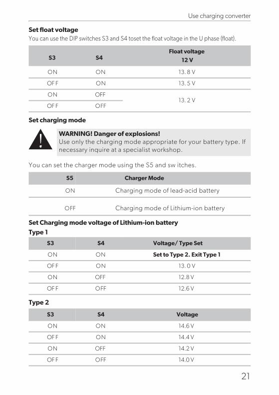
Set float voltageYou can use the DIP switches S3 and S4 toset the float voltage in the U phase (float).
S
Set Charging mode voltage of Lithium-ion battery
Type 1
Type 2
et charging mode
You can set the charger mode using the S5 and sw itches.
S3 S4Float voltage
12 V
WARNING! Danger of explosions!Use only the charging mode appropriate for your battery type. Ifnecessary inquire at a specialist workshop.
ON ON
OF F ON
ON OFF13. 2 V
13. 5 V
13. 8 V
OF F OFF
Charging mode of lead-acid battery
Charging mode of Lithium-ion battery
S5 Charger Mode
ON
OFF
ON ON
OF F ON
ON OFF 12.8 V
12.6 V
13. 0 V
OF F OFF
S3
Set to Type 2. Exit Type 1
Voltage/ Type Set S4
ON ON
OF F ON
ON OFF 14.2 V
14.6 V
14.4 V
14.0 VOF F OFF
S3 Voltage S4
!
Troubleshooting
22
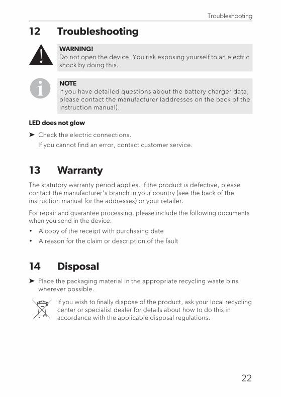
12 Troubleshooting
LED does not glow
Check the electric connections.
If you cannot find an error, contact customer service.
13 WarrantyThe statutory warranty period applies. If the product is defective, pleasecontact the manufacturer's branch in your country (see the back of theinstruction manual for the addresses) or your retailer.
For repair and guarantee processing, please include the following documentswhen you send in the device:
• A copy of the receipt with purchasing date
• A reason for the claim or description of the fault
14 DisposalPlace the packaging material in the appropriate recycling waste binswherever possible.
If you wish to finally dispose of the product, ask your local recyclingcenter or specialist dealer for details about how to do this inaccordance with the applicable disposal regulations.
WARNING! Do not open the device. You risk exposing yourself to an electricshock by doing this.
NOTE If you have detailed questions about the battery charger data,please contact the manufacturer (addresses on the back of theinstruction manual).
!

Technical data
23
Protective devices
DCC-1212-20 DCC-1212-40 DCC-1212-60
V21Transformation: 12 V
V21Nominal input voltage:
V61 – V8Input voltage range:
Charging current:
V7.41 – V2.31Charging voltage:
Output:
Residual ripple of outputvoltage at rated current:
< 50 mVeff
%09Efficiency up to:
A4.0 <Idle power consumption:
Ambient temperature foroperation: –20 °C to +50 °C
Ambient humidity: 95% Non-condensing
Dimensions (W x D x H):
1.88kg 2.40kg1.33kg
500W 750W250W
40 A 60 A20 A
Weight:
Inspection/certification:
12V
High-voltage, low-voltage, reverse polarityprotection (internal fuse)
:tupnI
8 V:tuo-tuc egatlov-woL
10 VLow-voltage restart:
16 VHigh-voltage shutdown:
15.5 VHigh-voltage restart:
nwodtuhS:erutarepmeT
I ,seyShort-circuit protection: pk
≤
261*175*68 mm 311*175*68 mm211*175*68 mm
→

Technical data
24
Temperature compensation
NOTE The temperature compensation is only effective if a RNG-DCC-TS temperature sensor is connected and the IU0U charging
V
0,8
–0,4
0,4
0
–0,8
–1,2
24 V
0,4
–0,2
0,2
0
–0,4
–0,60 54510155– 3525 4030 0502
°C
12 V
mode is selected.