Embed Size (px)
Citation preview

13
DC/DC Converters for Electric Vehicles
Monzer Al Sakka1, Joeri Van Mierlo1 and Hamid Gualous2 1Vrije Universiteit Brussel,
2Université de Caen Basse-Normandie 1Belgium,
2France
1. Introduction
The large number of automobiles in use around the world has caused and continues to
cause serious problems of environment and human life. Air pollution, global warming, and
the rapid depletion of the earth’s petroleum resources are now serious problems. Electric
Vehicles (EVs), Hybrid Electric Vehicles (HEVs) and Fuel Cell Electric Vehicles (FCEVs)
have been typically proposed to replace conventional vehicles in the near future. Most
electric and hybrid electric configurations use two energy storage devices, one with high
energy storage capability, called the “main energy system” (MES), and the other with high
power capability and reversibility, called the “rechargeable energy storage system” (RESS).
MES provides extended driving range, and RESS provides good acceleration and
regenerative braking. Energy storage or supply devices vary their output voltage with load
or state of charge and the high voltage of the DC-link create major challenges for vehicle
designers when integrating energy storage / supply devices with a traction drive. DC-DC
converters can be used to interface the elements in the electric power train by boosting or
chopping the voltage levels. Due to the automotive constraints, the power converter
structure has to be reliable, lightweight, small volume, with high efficiency, low
electromagnetic interference and low current/voltage ripple. Thus, in this chapter, a
comparative study on three DC/DC converters topologies (Conventional step-up dc-dc
converter, interleaved 4-channels step-up dc-dc converter with independent inductors and
Full-Bridge step-up dc-dc converter) is carried out. The modeling and the control of each
topology are presented. Simulations of 30KW DC/DC converter are carried out for each
topology. This study takes into account the weight, volume, current and voltage ripples,
Electromagnetic Interference (EMI) and the efficiency of each converter topology.
2. Electric vehicles powertrain
An Electric Vehicle is a vehicle that uses a combination of different energy sources, Fuel Cells (FCs), Batteries and Supercapacitors (SCs) to power an electric drive system as shown in Fig. 1. In EV the main energy source is assisted by one or more energy storage devices. Thereby the system cost, mass, and volume can be decreased, and a significant better performance can be obtained. Two often used energy storage devices are batteries and SCS. They can be connected to the fuel cell stack in many ways. A simple configuration is to
www.intechopen.com

Electric Vehicles – Modelling and Simulations
310
directly connect two devices in parallel, (FC/battery, FC/SC, or battery/SC). However, in this way the power drawn from each device cannot be controlled, but is passively determined by the impedance of the devices. The impedance depends on many parameters, e.g. temperature, state-of-charge, health, and point of operation. Each device might therefore be operated at an inappropriate condition, e.g. health and efficiency. The voltage characteristics also have to match perfectly of the two devices, and only a fraction of the range of operation of the devices can be utilized, e.g. in a fuel cell battery configuration the fuel cell must provide almost the same power all the time due to the fixed voltage of the battery, and in a battery/supercapacitor configuration only a fraction of the energy exchange capability of the supercapacitor can be used. This is again due to the nearly constant voltage of the battery. By introducing DC/DC converters one can chose the voltage variation of the devices and the power of each device can be controlled (Schaltz & Rasmussen, 2008).
Supercapacitors
Battery
Tra
nsm
issi
on
DC/AC EM
DC
_lin
k
DC/DC
DC/DC
DC/DC
Fuel Cell
Fig. 1. Electric vehicle drive system.
In reference (Schaltz & Rasmussen, 2008), 10 cases of combining the fuel cell with the battery, SCs, or both are investigated. The system volume, mass, efficiency, and battery lifetime were compared. It is concluded that when SCs are the only energy storage device the system becomes too big and heavy. A fuel cell/battery/supercapacitors hybrid provides the longest life time of the batteries. It can be noticed that the use of high power DC/DC converters is necessary for EV power supply system. The power of the DC/DC converter depends on the characteristics of the vehicle such as top speed, acceleration time from 0 to 100 Km/h, weight, maximum torque, and power profile (peak power, continuous power) (Büchi et al., 2006). Generally, for passenger cars, the power of the converter is more than 20 KW and it can go up to 100 KW.
3. DC/DC converters for electric vehicles
The different configurations of EV power supply show that at least one DC/DC converter is necessary to interface the FC, the Battery or the Supercapacitors module to the DC-link. In electric engineering, a DC to DC converter is a category of power converters and it is an electric circuit which converts a source of direct current (DC) from one voltage level to another, by storing the input energy temporarily and then releasing that energy to the
www.intechopen.com

DC/DC Converters for Electric Vehicles
311
output at a different voltage. The storage may be in either magnetic field storage components (inductors, transformers) or electric field storage components (capacitors). DC/DC converters can be designed to transfer power in only one direction, from the input to the output. However, almost all DC/DC converter topologies can be made bi-directional. A bi-directional converter can move power in either direction, which is useful in applications requiring regenerative braking. The amount of power flow between the input and the output can be controlled by adjusting the duty cycle (ratio of on/off time of the switch). Usually, this is done to control the output voltage, the input current, the output current, or to maintain a constant power. Transformer-based converters may provide isolation between the input and the output. The main drawbacks of switching converters include complexity, electronic noise and high cost for some topologies. Many different types of DC/DC power converters are proposed in literature (Chiu & Lin, 2006), (Fengyan et al., 2006). The most common DC/DC converters can be grouped as follows:
3.1 Non-isolated converters The non-isolated converters type is generally used where the voltage needs to be stepped up or down by a relatively small ratio (less than 4:1). And when there is no problem with the output and input having no dielectric isolation. There are five main types of converter in this non-isolated group, usually called the buck, boost, buck-boost, Cuk and charge-pump converters. The buck converter is used for voltage step-down, while the boost converter is used for voltage step-up. The buck-boost and Cuk converters can be used for either step-down or step-up. The charge-pump converter is used for either voltage step-up or voltage inversion, but only in relatively low power applications.
3.2 Isolated converters Usually, in this type of converters a high frequency transformer is used. In the applications where the output needs to be completely isolated from the input, an isolated converter is necessary. There are many types of converters in this group such as Half-Bridge, Full-Bridge, Fly-back, Forward and Push-Pull DC/DC converters (Garcia et al., 2005), (Cacciato et al., 2004). All of these converters can be used as bi-directional converters and the ratio of stepping down or stepping up the voltage is high.
3.3 Electric vehicle converters requirements In case of interfacing the Fuel Cell, the DC/DC converter is used to boost the Fuel Cell voltage and to regulate the DC-link voltage. However, a reversible DC/DC converter is needed to interface the SCs module. A wide variety of DC-DC converters topologies, including structures with direct energy conversion, structures with intermediate storage components (with or without transformer coupling), have been published (Lachichi & Schofield, 2006), (Yu & Lai, 2008), (Bouhalli et al., 2008). However some design considerations are essential for automotive applications: Light weight,
High efficiency, Small volume, Low electromagnetic interference, Low current ripple drawn from the Fuel Cell or the battery,
The step up function of the converter,
www.intechopen.com

Electric Vehicles – Modelling and Simulations
312
Control of the DC/DC converter power flow subject to the wide voltage variation on the converter input.
Each converter topology has its advantages and its drawbacks. For example, The DC/DC boost converter does not meet the criteria of electrical isolation. Moreover, the large variance in magnitude between the input and output imposes severe stresses on the switch and this topology suffers from high current and voltage ripples and also big volume and weight. A basic interleaved multichannel DC/DC converter topology permits to reduce the input and output current and voltage ripples, to reduce the volume and weight of the inductors and to increase the efficiency. These structures, however, can not work efficiently when a high voltage step-up ratio is required since the duty cycle is limited by circuit impedance leading to a maximum step-up ratio of approximately 4. Hence, two series connected step-up converters would be required to achieve the specific voltage gain of the application specification. A full-bridge DC/DC converter is the most frequently implemented circuit configuration for fuel-cell power conditioning when electrical isolation is required. The full bridge DC/DC converter is suitable for high-power transmission because switch voltage and current are not high. It has small input and output current and voltage ripples. The full-bridge topology is a favorite for zero voltage switching (ZVS) pulse width modulation (PWM) techniques.
4. Electromagnetic compatibility regulation
Fast semiconductor devices make it possible to have high speed and high frequency
switching in power electronics converters. High speed switching helps to reduce weight and
volume of equipment; however, it causes some undesirable effects such as radio frequency
interference (RFI) emission. It is believed that high dv/dt or di/dt due to modern power
device switching is mainly responsible for the EMI emissions. Application of electrical
equipment especially static power electronic converters in different equipment is increasing
more and more. Power electronics converters are considered as an important source of
electromagnetic interference and have undesirable effects on the electric networks. Some
residential, commercial and especially medical consumers are very sensitive to power
system disturbances including voltage and frequency variations. Also, for Electric vehicle,
there is limitation of the EMI. The best solution to reduce the interference and improve the
power quality is complying national or international EMC regulations. CISPR, IEC, FCC and
VDE are among the best known organizations from Europe, USA and Germany who are
responsible for determining and publishing the most important EMC regulations.
Compliance of regulations is evaluated by comparison of measured or calculated conducted
interference level in the mentioned frequency range with the stated requirements in
regulations. In European community compliance of regulation is mandatory and products
must have certified label to show covering of requirements (Farhadi & Jalilian, 2006). For
Electric Vehicle, the maximum interference level should meet the DIN VDE 0879 standard.
The limits in this standard are almost the same as the class B of VDE 0871 requirement and
limitation on conducted emission.
4.1 Electromagnetic conducted interference measurement A Line Impedance Stabilization Network (LISN) is typically designed to allow for measurements of the electromagnetic interference existing on the power line, it is a device
www.intechopen.com

DC/DC Converters for Electric Vehicles
313
used to create known impedance on power lines of electrical equipment during electromagnetic interference testing. The stated situation is shown in Fig. 2.
DC/DC converter
Electrical Source
LISN Load
Interference
Measurements
Fig. 2. LISN placement to measure conducted interference.
Variation of level of signal at the output of LISN versus frequency is the spectrum of interference. The electromagnetic compatibility of a device can be evaluated by comparison of its interference spectrum with the standard limitations. The level of signal at the output of LISN in frequency range 10 kHz up to 30 MHz or 150 kHz up to 30 MHz is criteria of compatibility and should be under the standard limitations. Converting the results to dBuV (Equation 1) makes it possible to compare the spectrum of interference with standard requirements. In practical situations, the LISN output is connected to a spectrum analyzer and interference measurement is carried out. But for modeling and simulation purposes, the LISN output spectrum must be calculated using appropriate software.
( ) ( )10 10620log 20log 120
10
xdB V x xm -
æ ö÷ç= = +÷ç ÷÷çè ø (1)
5. Losses in a power converter
The considered losses in a power converter are the losses produced by the semiconductors switches (IGBTs and DIODES) and the passive components (capacitors and inductors). The aim of this explanation is only to give an idea about the losses estimation. This estimation is used in this study to calculate the efficiency. The efficiency of a power converter is given by:
_
_
Input power
Input power
P Losses
Ph
-=
å (2)
5.1 IGBT conduction and switching losses The IGBT conduction losses are given by:
2
_ 0 _IGBT cond CE IGBT CE IGBT rmsP V I r I= + (3)
The IGBT characteristics (VCE0 and rCE) are given in the datasheet of the IGBT. <IIGBT> and IIGBT_rms are the average current and the rms current of the IGBT, respectively. The IGBT switching losses are given by:
( )_IGBT switch on off sP E E f= + (4)
www.intechopen.com

Electric Vehicles – Modelling and Simulations
314
Where, fs is the switching frequency. Eon and Eoff are the switching losses during the switching on and switching off, respectively. Energy values are generally given for specific test conditions (Voltage test condition VCC). Thus, to adapt these values to others test conditions, as an estimation the IGBT switching losses are given by (Garcia Arregui, 2007):
( ) ( )( )_ _ _IGBT
IGBT switch on IGBT on off IGBT off sCC
VP E I E I f
V= + (5)
5.2 Diode conduction and switching losses The Diode conduction losses are given by:
2_ 0 _D cond F D F D rmsP V I r I= + (6)
The Diode characteristics (VF0 and rF) are given in the Diode datasheet. <ID> and ID_rms are the average current and the rms current of the Diode, respectively. The Diode switching losses are given by:
_D switch rr sP E f= (7)
Where, fs is the switching frequency. Err is the recovery energy. The recovery energy is given as a function of the voltage, the current, the turn-on and turn off resistances and for a specific test conditions. To adapt the previous expression to another test conditions, as estimation the diode switching losses are given by:
( )_D
D switch rr D sCC
VP E I f
V= (8)
5.3 Capacitor losses The capacitor losses are calculated thanks to the equivalent resistance of the capacitor, which is usually given in the datasheets. The capacitor losses are given by:
2
_Capacitor C C rmsP r I= (9)
Where, rC is the equivalent resistance of the capacitor and IC_rms is the rms current value of the capacitor.
5.4 Inductors losses In an inductor, there are iron and copper losses. Core losses (or iron losses) are energy losses
that occur in electrical transformers and inductors using magnetic cores. The losses are due
to a variety of mechanisms related to the fluctuating magnetic field, such as eddy currents
and hysteretic phenomena. Most of the energy is released as heat, although some may
appear as noise. These losses are estimated based on charts supplied by magnetic core
manufacturer. To estimate the total iron losses, the weight of core should be multiplied by
the obtained value for a specific flux density and switching frequency. The inductor iron
losses are given by:
www.intechopen.com

DC/DC Converters for Electric Vehicles
315
_L Core core coreP W P= (10)
Where, Wcore is the weight of the core and Pcore is the iron losses per Kg. The copper losses or the conduction losses in the inductor are given by:
2_ _L copper L L rmsP r I= (11)
Where, rL is the resistance of the inductor and IL_rms is the rms current value of the inductor.
6. Design, modeling, control and simulation results of 3 DC/DC converters
The modeling of studied converters is done by using the Simpower tools of Matlab/Simulink, and it takes into account the IGBT and Diodes parameters (real components) and the inductors and capacitors losses. To achieve accurate voltage regulation, two control loops are used as shown in Fig. 3. This control mode (current mode control) requires knowledge of the inductor current, which is controlled via the inner loop. The outer loop manages the output voltage error by commanding the necessary current. The control was done using RST controllers.
DC/DC converter
RST Voltage
Vref Iref RST Current
PWM
generator
Duty cycle PWM
Vmea
Imea
Fig. 3. Block diagram of control mode.
6.1 RST controller The canonical structure of the RST controller is presented in Fig. 4. This structure has two degrees of freedom, i.e., the digital filters R and S are designed in order to achieve the desired regulation performance, and the digital filter T is designed afterwards in order to achieve the desired tracking and regulation. This structure allows achievement of different levels of performance in tracking and regulation. The case of a controller operating on the regulation error (which does not allow the independent specification of tracking and regulation performance) corresponds to T=R. Digital PID controller can also be represented in this form, leading to particular choices of R, S and T (Landau, 1998).
+- DAC 1zC
RST controllerADC
sH
1zR
11 zS 1zT 1zU sU sY
1zY
Fig. 4. The RST canonical structure of a digital controller
www.intechopen.com

Electric Vehicles – Modelling and Simulations
316
The equation of the RST canonical controller is give by:
( ) ( ) ( ) ( ) ( ) ( )1 1 1 1 1 1S z U z R z Y z T z C z- - - - - -⋅ + ⋅ = ⋅ (12)
Where: U(z-1) : the input of the plant H(s), Y(z-1) : the output of the plant H(s), C(z-1) : the desired tracking trajectory. The polynomials R(z-1), S(z-1) and T(z-1) have the following form:
( )( )( )
1 10 1
1 10 1
1 10 1
...
...
...
R
R
S
S
T
T
nn
nn
nn
R z r r z r z
S z s s z s z
T z t t z t z
-- -
-- -
-- -
ìï = + + +ïïïïï = + + +íïïïï = + + +ïïî
(13)
The plant and closed-loop models are expressed by expression 14 and expression 15 respectively:
( )( )( )
( )( )
Y s B sH s
U s A s= = (14)
( )( )( )
( )( )
CLCL
CL
Y s B sH s
C s A s= = (15)
A formal discretization leads to both discrete-time transfer functions as follows, with m<=n and d is a pure time delay.
( ) ( )( )
1 1 21 1 2
1 211 2
...
...
md d m
nn
B z b z b z b zH z z z
a z a z a zA z
- - - -- - -
- - --
+ + += =
+ + + (16)
( ) ( )( )
( )( )
1 1
1
1 1
CL
CL
CL
Y z B zH z
C z A z
- --
- -= = (17)
The closed-loop transfer operator (between C(z-1) and Y(z-1)) is given by:
( ) ( ) ( )( ) ( ) ( ) ( )
( )( )
1 1 1
1
1 1 1 1 1
CL
CL
CL
B z T z B zH z
A z S z B z R z A z
- - --
- - - - -= =
+ (18)
R, S and T polynomials are determined in order to obtain an imposed closed-loop system. Resolving the Diophantine equation (or Bezout’s identity) AS+BR=ACL leads to the identification of S and R polynomials. The polynomial T is determined from the equation BT=BCL.
6.1.1 Calculation of RST parameters used in this study The current and voltage control loops controllers of the three DC/DC topologies compared in this study use the same type of transfer function in open loop which is given by:
www.intechopen.com

DC/DC Converters for Electric Vehicles
317
( )( )( )
1Y sH s
U s ks= = (19)
A formal discretization leads to the discrete-time transfer function as follows:
( ) ( ) ( )
( )( )
( )( )
1 1
111
2 1 1
11
111
s s
H z z TFZ H ss
B zT Tz zz
k k z A zz
- -
---
- -
æ ö÷ç= - ÷ç ÷÷çè ø
= - = =--
(20)
The sampling period Ts used in the control is equal to the switching frequency of PWM signals. Choosing the polynomials R(z-1) and S(z-1): The system in closed-loop should be a two order system (deg(ACL(z-1))=2). Error Specification: no error in steady state step response and rejection of disturbance. The polynomials R(z-1) and S(z-1) are given by:
( )( ) ( )( ) ( )( )( )( )
1 1 1
1 1
1 10 1
deg deg deg 1
1
CLS z R z A z
S z z
R z r r z
- - -
- -
- -
= = -
ìï = -ïïíï = +ïïî
(21)
In addition, in order to guarantee a unity static gain in closed-loop:
( ) ( )
( ) ( ) ( ) ( )( )
( )1
10 1
1lim 1
1 1 1 1 1
1 0
CLz
B TH z
A S B R T R r r
S
-
ìï ⋅ï = =ïï + = = +íïïï =ïî
(22)
Calculation of S(z-1) and R(z-1) coefficients: The desired closed loop polynomial is given by:
( ) ( ) ( ) ( ) ( )1 1 1 1 1 1 21 21CLA z A z S z B z R z p z p z- - - - - - -= + = + + (23)
Replacing A(z-1), S(z-1), B(z-1) and R(z-1) by their expressions in Equation 23. The obtained polynomial of the desired closed-loop is represented by:
( )1 1 2
1 2
1 20 1
1
1 2 2
CL
s s
A z p z p z
T Tr z r z
k k
- - -
- -
= + +
æ ö æ ö÷ ÷ç ç= + - + -÷ ÷ç ç÷ ÷÷ ÷ç çè ø è ø
(24)
By identification the coefficients r0 and r1 are given by:
( )
( )
0 1
1 2
2
1
s
s
kr p
T
kr p
T
ìïï = +ïïïïíïï = -ïïïïî
(26)
www.intechopen.com
Electric Vehicles – Modelling and Simulations
318
The coefficients p1 and p2 are determined according to the desired current and voltage closed-loop dynamics. Finally, the desired closed loop polynomial can be represented by:
( ) ( )21 11 n sTCLA z z e w-- -= - (26)
Where, ωn is the bandwidth of the control loop.
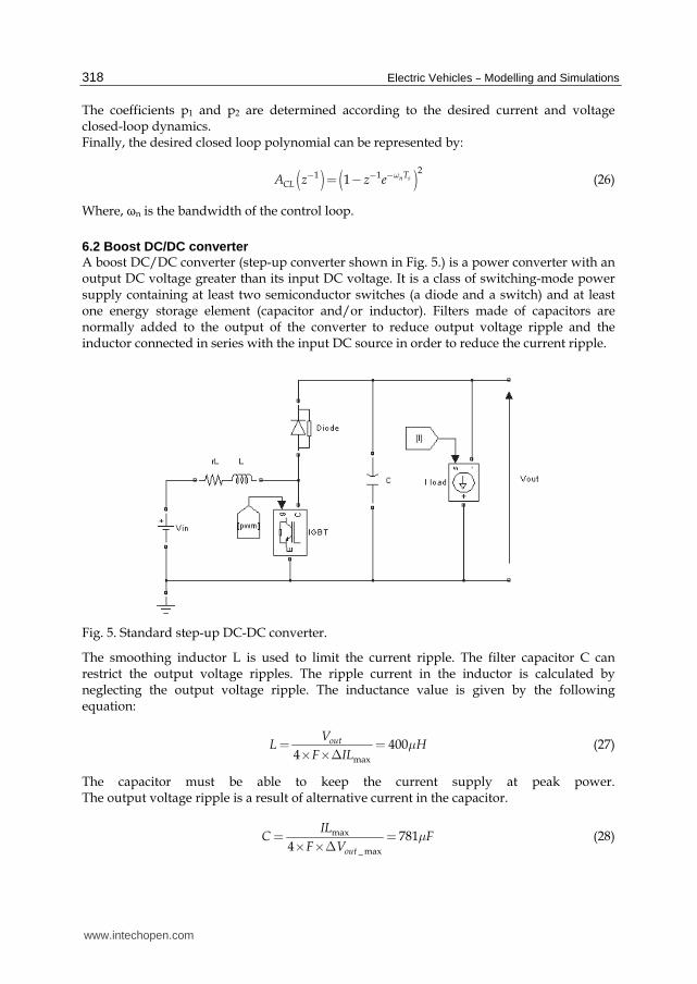
6.2 Boost DC/DC converter A boost DC/DC converter (step-up converter shown in Fig. 5.) is a power converter with an output DC voltage greater than its input DC voltage. It is a class of switching-mode power supply containing at least two semiconductor switches (a diode and a switch) and at least one energy storage element (capacitor and/or inductor). Filters made of capacitors are normally added to the output of the converter to reduce output voltage ripple and the inductor connected in series with the input DC source in order to reduce the current ripple.
Fig. 5. Standard step-up DC-DC converter.
The smoothing inductor L is used to limit the current ripple. The filter capacitor C can restrict the output voltage ripples. The ripple current in the inductor is calculated by neglecting the output voltage ripple. The inductance value is given by the following equation:
max
4004
outVL H
F ILm= =
´ ´D (27)
The capacitor must be able to keep the current supply at peak power. The output voltage ripple is a result of alternative current in the capacitor.
max
_ max
7814 out
ILC F
F Vm= =
´ ´D (28)
www.intechopen.com

DC/DC Converters for Electric Vehicles
319
Where:
Vout : the output voltage,
∆ILmax : the inductor current ripple,
F : the switching frequency.
ILmax : the maximum input current,
∆Vout_max : the maximum output voltage ripple. Table 1 shows the specifications of the converter. The inductor current ripple value is desired to be less than 5% of the maximum input current in the case of interfacing a Fuel Cell. A ripple factor less than 4% for the Fuel Cell’s output current will have negligible impact on the conditions within the Fuel Cell diffusion layer and thus will not severely impact the Fuel Cell lifetime (Yu et al., 2007).
∆Vout_max Output voltage ripple (1% of Vout = 4 V)
Vout Output voltage (400 V)
F Switching frequency (20 KHz)
ILmax Inductor current (250 A)
∆ILmax Inductor current ripple (5% of ILmax = 12.5 A)
Table 1. Standard boost DC-DC converter parameters
6.2.1 Modeling and control The output voltage is adjustable via the duty cycle α of the PWM signal switching the IGBT as given in the following expression:
1
1out
in
V
V a=
- (29)
The input voltage Vin is considered as constant (200V). The inductor and capacitor resistances are not taken into account in the analysis of the converter. The converter can be modeled by the following system of equations:
( )
( )
1
1
Lin out
outL out
div L u v
dtdv
i u C idt
ìïï = + -ïïïíïï - = +ïïïî
(30)
This model can be used directly to simulate the converter. By replacing the variable u by its average value which is the duty cycle during a sampling period makes it possible to obtain the average model of the converter as illustrated in the following system of differential equations:
( )
( )
1
1
Lin out
outout
div L v
dtdv
il C idt
a
a
ìïï = + -ïïïíïï - = +ïïïî
(31)
www.intechopen.com
Electric Vehicles – Modelling and Simulations
320
Current control loop
The current control loop guarantees limited variations of the current trough the inductor during important load variations. The inductor current and voltage models are given by Equation 32 and Equation 33, respectively.
( ) ( ) ( )( ) ( )( )11in outIL s V s s V s
Lsa= - - ⋅ (32)
( ) ( ) ( )( ) ( )1in outVL s V s s V sa= - - ⋅ (33)
To make it simple to define a controller, the behavior of the system should be linearized. The linearization is done by using an inverse model. Thus an expression between the output of corrector and the voltage of the inductor should be found (Lachaize, 2004). Thus, the following expression is proposed:
( )( ) ( )
( )1 in
out
VL s V ss
V sa
¢ -= + (34)
Where, VL’ is a new control variable represents the voltage reference of the inductor. Thus, a linear transfer between VL’(s) and IL(s) is obtained by:
( )( )( )1
1IL sT s
VL s Ls= =
¢ (35)
The structure of the regulator is a RST form. The polynomials R, S and T are calculated using the methodology explained above. The bandwidth of the current loop ωi should be ten times lower than the switching frequency.
2,
10 10i i
f ff
pw£ £ (36)
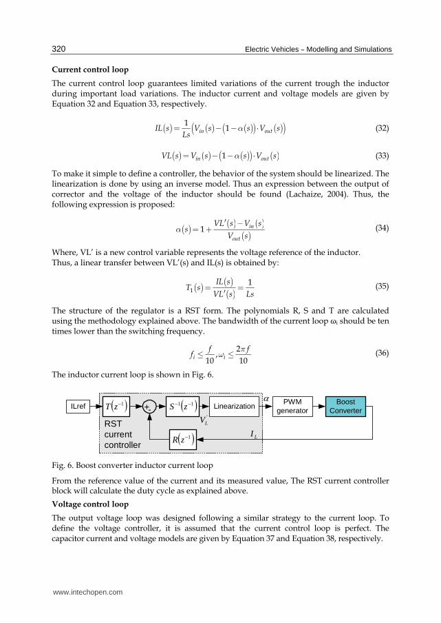
The inductor current loop is shown in Fig. 6.
ILref +- LinearizationBoost
ConverterPWM
generator
'
LV
LIRSTcurrentcontroller
1zR
1zT 11 zS
Fig. 6. Boost converter inductor current loop
From the reference value of the current and its measured value, The RST current controller block will calculate the duty cycle as explained above.
Voltage control loop
The output voltage loop was designed following a similar strategy to the current loop. To define the voltage controller, it is assumed that the current control loop is perfect. The capacitor current and voltage models are given by Equation 37 and Equation 38, respectively.
www.intechopen.com

DC/DC Converters for Electric Vehicles
321
( ) ( )( ) ( ) ( )1 outIC s s IL s I sa= - ⋅ - (37)
( ) ( )( ) ( ) ( )( )11 outVC s s IL s I s
Csa= - ⋅ - (38)
The linearization of the system is done by the following expression:
( )( ) ( )( )
( )( )
( )( )( )
( ) ( )( )
1
out
outLref out
in
IC s I sIL s
s
V sI s IC s I s
V s
a
¢ +=
-
¢ = +
(39)
Where IC’ is a new control variable represents the current reference of the capacitor. Thus, a linear transfer between Vout(s) and IC’(s) is obtained by:
( ) ( )( )2
1outV sT s
IC s Cs= =
¢ (40)
The bandwidth of the voltage loop ωv should be ten times lower than the current loop bandwidth ωi which means hundred times lower than the switching frequency.
2
,100 100
v v
f ff
pw£ £ (41)
The output voltage control loop is shown in Fig. 7.
Vref +- Linearization'CI
BoostConverter
PWMgenerator
LrefI
RST CurrentLoop
outV LIRSTvoltagecontroller
1zR
1zT 11 zS
Fig. 7. Boost converter output voltage control loop.
The RST voltage controller operates in the same as the current controller and it has to
calculate the current reference which will be the input of the current controller.
Simulation results
The current and voltage ripples are about 10 Amps and 2 Volts, respectively. The results show that the converter follows the demand on power thanks to the good control. The efficiency of the boost dc/dc converter is about 83% at full load as shown in Fig. 8. Fig. 9 shows the spectrum of the output signal of the LISN as described in the section “Electromagnetic compatibility regulation”. It is seen that the level of conducted interference due to converter is not tolerable by the regulations. As a consequence EMI filter suppression is necessary to meet the terms the regulations.
www.intechopen.com

Electric Vehicles – Modelling and Simulations
322
10 20 30 40 50 60 70 8080
82
84
86
88
90
92
94
96
98
100
Current [A]
Eff
icie
ncy
[%]
Efficiency Standard BOOST 30KW
Efficiency
Fig. 8. Boost converter efficiency versus current load
0 150 KHz500 KHz 5 MHZ 10 MHz 15 MHz 20 MHz 25 MHz 30 MHz0
40
50
60
70
80
100
150
Frequency [Hz]
Spec
trum
[dBu
V]
EMI BOOST 30KW without EMI filter
VDE Class AVDE Class B
IEC Class A
IEC Class B
Fig. 9. EMI simulation results of boost DC/DC converter.
www.intechopen.com

DC/DC Converters for Electric Vehicles
323
6.3 Interleaved 4-channel DC/DC converter Fig. 10 shows a basic interleaved step-up converter of 4 identical levels where the inductances L1 to L4 are built by a separate magnetic core. The gate signals to the power switching devices are successively phase shifted by T/N where T is the switching period and N the number of channels. Thus, the current delivered by the electric source is shared equally between each basic step-up converter level and has a ripple content of period T/N (Destraz et al., 2006).
Fig. 10. Interleaved 4-channels step-up DC-DC converter.
The design of the 4-channels converter is the same like the boost one. The output voltage is adjustable via the duty cycle α of the PWM signal switching the IGBTs as given in the following expression:
1
1out
in
V
V a=
- (42)
Where:
α : the duty cycle,
Vin : the input voltage,
Vout : the output voltage. The inductor value of each channel is given by the following expression:
_ max
1004
outk
In
VL H
F N Im= =
´ ´ ´D (43)
Where:
N : the number of channels,
∆IIn_max : the input current ripple,
F : the switching frequency.
IIn_max : the maximum input current,
∆Vout_max : the maximum output voltage ripple.
www.intechopen.com

Electric Vehicles – Modelling and Simulations
324
As control signals are interleaved and the phase angle is 360°/N, the frequency of the total current is N times higher than the switching frequency F. The filter capacitor of the interleaved N-channel dc-dc converter is given by the following expression:
_ maxmin
_ max
1954
Inf
out
IC F
F N Vm= =
´ ´ ´D (44)
Table 2 shows the specifications of the converter.
∆Vout_max Output voltage ripple (1% of Vout = 4 V)
Vout Output voltage (400 V)
F Switching frequency (20 KHz)
IIn_max Inductor current (250 A)
∆IIn_max Input current ripple (5% of IIn_max = 12.5 A)
Table 2. Interleaved 4-channels DC-DC converter parameters
6.3.1 Modeling and control The 4-channel converter is modeled in the same way of the boost converter. The current and voltage loop are designed also using the same methodology used for boost converter. The calculated current reference is divided by 4 (number of channels). The output voltage control loop is shown is Fig. 11.
Vref +- Linearization'CI
4-channelBoost
Converter
4 PWMgeneratorshift (T/4)
LrefI
RST CurrentLoop
outV chLI _
RSTvoltagecontroller
1/4
chLrefI _
1zR
1zT 11 zS
Fig. 11. 4-channels converter output voltage control loop.
In the proposed control, the duty cycle is calculated from one reference channel. The same duty cycle is applied to the other channels. The PWM signals are shifted by 360/4°. Simulation results Thanks to the interleaving technique, the total current ripples are reduced and can be neglected; the voltage ripples are about 0.5V. The results show that the converter follows the demand on power. The efficiency of the 4-channels dc/dc converter is about 92% at full load as shown in Fig. 12. The drop in efficiency is due to the changing from discontinuous mode (DCM) to continuous mode (CM). In DCM, the technique of zero voltage switching (ZVS) is operating which permits to reduce the switching losses in the switch, thus the efficiency is increased. Fig. 13 shows the EMI of the interleaved 4-channels DC/DC converter. It is seen that the level of conducted interference due to converter is not tolerable by the regulations. As a consequence this converter without EMI filter suppression does not meet the terms of the regulations. Thus, EMI filter suppression is required.
www.intechopen.com

DC/DC Converters for Electric Vehicles
325
25 30 35 40 45 50 55 60 65 70 75 8080
82
84
86
88
90
92
94
96
98
100
Current [A]
Eff
icie
ncy
[%]
Efficiency 4-channels 30KW
Efficiency
Fig. 12. 4-channels converter efficiency versus current load.
0150 KHz500 KHz 5 MHz 10 MHz 15 MHz 20 MHz 25 MHz 30 MHz0
4 0
5 0
6 0
7 0
8 0
10 0
15 0
Frequency [Hz]
Spe
ctru
m [d
BuV
]
EMI I nter leave d 4-channels 30KW without EMI filter
VDE Class AVDE Class B
IEC Class A
IEC Class B
Fig. 13. EMI simulation results of interleaved 4-channels DC/DC converter.
www.intechopen.com
Electric Vehicles – Modelling and Simulations
326
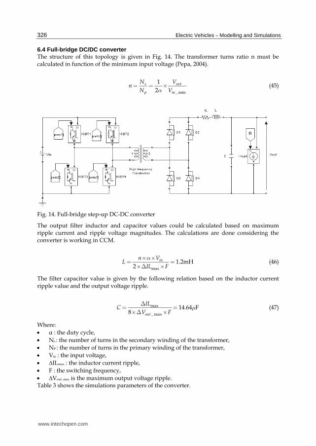
6.4 Full-bridge DC/DC converter The structure of this topology is given in Fig. 14. The transformer turns ratio n must be calculated in function of the minimum input voltage (Pepa, 2004).
_ min
1
2s out
p in
N Vn
N Va= = ´ (45)
Fig. 14. Full-bridge step-up DC-DC converter
The output filter inductor and capacitor values could be calculated based on maximum ripple current and ripple voltage magnitudes. The calculations are done considering the converter is working in CCM.
max
1.2mH2
inn VL
IL F
a´ ´= =
´D ´ (46)
The filter capacitor value is given by the following relation based on the inductor current ripple value and the output voltage ripple.
max
_ max
14.64 F8 out
ILC
V Fm
D= =
´D ´ (47)
Where:
α : the duty cycle,
Ns : the number of turns in the secondary winding of the transformer,
NP : the number of turns in the primary winding of the transformer,
Vin : the input voltage,
∆ILmax : the inductor current ripple,
F : the switching frequency,
∆Vout_max is the maximum output voltage ripple. Table 3 shows the simulations parameters of the converter.
www.intechopen.com
DC/DC Converters for Electric Vehicles
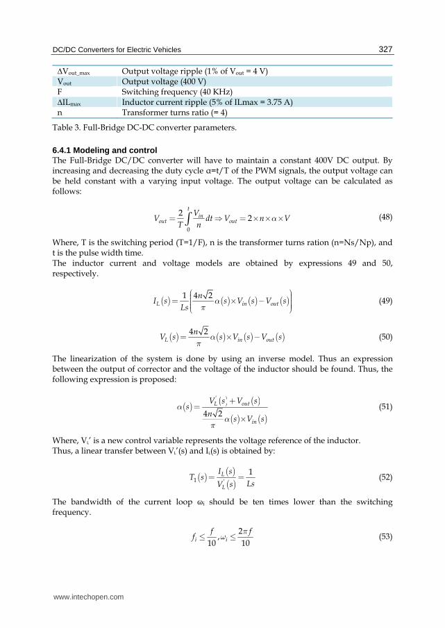
327
∆Vout_max Output voltage ripple (1% of Vout = 4 V) Vout Output voltage (400 V) F Switching frequency (40 KHz) ∆ILmax Inductor current ripple (5% of ILmax = 3.75 A) n Transformer turns ratio (= 4)
Table 3. Full-Bridge DC-DC converter parameters.
6.4.1 Modeling and control The Full-Bridge DC/DC converter will have to maintain a constant 400V DC output. By increasing and decreasing the duty cycle α=t/T of the PWM signals, the output voltage can be held constant with a varying input voltage. The output voltage can be calculated as follows:
0
22
tin
out out
VV dt V n V
T na= = ´ ´ ´ò (48)
Where, T is the switching period (T=1/F), n is the transformer turns ration (n=Ns/Np), and t is the pulse width time. The inductor current and voltage models are obtained by expressions 49 and 50, respectively.
( ) ( ) ( ) ( )1 4 2L in out
nI s s V s V s
Lsa
p
æ ö÷ç ÷ç= ´ - ÷ç ÷÷çè ø (49)
( ) ( ) ( ) ( )4 2L in out
nV s s V s V sa
p= ´ - (50)
The linearization of the system is done by using an inverse model. Thus an expression between the output of corrector and the voltage of the inductor should be found. Thus, the following expression is proposed:
( )( ) ( )
( ) ( )
'
4 2
L out
in
V s V ss
ns V s
aa
p
+=
´ (51)
Where, VL’ is a new control variable represents the voltage reference of the inductor. Thus, a linear transfer between VL’(s) and IL(s) is obtained by:
( ) ( )( )1 '
1L
L
I sT s
LsV s= = (52)
The bandwidth of the current loop ωi should be ten times lower than the switching frequency.
2
,10 10
i i
f ff
pw£ £ (53)
www.intechopen.com

Electric Vehicles – Modelling and Simulations
328
The inductor current loop is shown in Fig. 15.
ILref +- Linearization
'LV
LIRSTcurrentcontroller
FullBridgeBoost
Converter
2 PWMgeneratorshift (T/2)
1zT
1zR
11 zS
Fig. 15. Full-bridge converter inductor current control loop.
The output voltage loop was designed following a similar strategy to the current loop. To define the voltage controller, it is assumed that the current control loop is perfect. The capacitor current and voltage models are obtained by expressions 54 and 55:
( ) ( ) ( )C L outI s I s I s= - (54)
( ) ( ) ( )( )1C L outV s I s I s
Cs= - (55)
The linearization of the system is done by the following expression:
( ) ( ) ( ) ( ) ( ) ( )' '
C CL out Lref outI s I s I s I s I s I s= + = + (56)
Where I’c is a new control variable represents the current reference of the capacitor. Thus, a linear transfer between Vout(s) and I’c(s) is obtained by:
( ) ( )( )2 '
1out
C
V sT s
CsI s= = (57)
The bandwidth of the voltage loop ωv should be ten times lower than the current loop bandwidth ωi which means hundred times lower than the switching frequency.
2
,100 100
v v
f ff
pw£ £ (58)
The output voltage control loop is shown in Fig. 16.
Vref +- Linearization'CI LrefI
RST CurrentLoop
outV LIRSTvoltagecontroller
FullBridgeBoost
Converter
2 PWMgeneratorshift (T/2)
1zT
1zR
11 zS
Fig. 16. Full-bridge converter output voltage control loop.
www.intechopen.com

DC/DC Converters for Electric Vehicles
329
Simulation results
The efficiency of the Full-bridge dc/dc converter is about 91.5% at full load as shown in Fig. 17. The efficiency of this converter can be increased by using phase shifted PWM control and zero voltage switching ZVS technique.
10 20 30 40 50 60 70 8080
82
84
86
88
90
92
94
96
98
100
Current [A]
Eff
icie
ncy
[%]
Efficiency Full-Bridge 30KW
Efficiency
Fig. 17. Full-bridge converter efficiency versus current load.
Fig. 18 shows the spectrum of the EMI of the Full-Bridge converter. The level of conducted interference is not tolerable by the regulations. As a consequence EMI filter suppression is necessary to meet the terms the regulations.
0 150 KHz500 KHz 5 MHz 10 MHz 15 MHz 20 MHz 25 MHz 30 MHz0
40
50
60
70
80
100
140
Frequency [Hz]
Spec
trum
[dBu
V]
EMI Full-Bridge 30KW without EMI filter
VDE Class AVDE Class B
IEC Class A
IEC Class B
Fig. 18. EMI simulation results of Full-Bridge DC/DC converter.
www.intechopen.com
Electric Vehicles – Modelling and Simulations
330
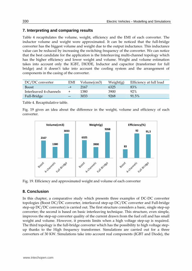
7. Interpreting and comparing results
Table 4 recapitulates the volume, weight, efficiency and the EMI of each converter. The inductor volume and weight were approximated. It can be noticed that the full-bridge converter has the biggest volume and weight due to the output inductance. This inductance value can be reduced by increasing the switching frequency of the converter. We can notice that the best candidate for the application is the Interleaving multi-channel topology which has the higher efficiency and lower weight and volume. Weight and volume estimation takes into account only the IGBT, DIODE, Inductor and capacitor (transformer for full bridge) and it doesn’t take into account the cooling system and the arrangement of components in the casing of the converter.
DC/DC converter EMI Volume(cm3) Weight(g) Efficiency at full load
Boost -+ 2167 6325 83% Interleaved 4-channels + 1380 3900 92% Full-Bridge -- 3033 9268 91.5%
Table 4. Recapitulative table.
Fig. 19 gives an idea about the difference in the weight, volume and efficiency of each converter.
2167
1380
3033
Volume(cm3)
6325
3900
9268
Weight(g)
83
92 91,5
Efficiency(%)
Fig. 19. Efficiency and approximated weight and volume of each converter
8. Conclusion
In this chapter, a comparative study which presents three examples of DC-DC converter topologies (Boost DC/DC converter, interleaved step-up DC/DC converter and Full-bridge step-up DC/DC converter) is carried out. The first structure considers a basic, single step-up converter; the second is based on basic interleaving technique. This structure, even simple, improves the step-up converter quality of the current drawn from the fuel cell and has small weight and volume. However, it presents limits when a high voltage step-up is required. The third topology is the full-bridge converter which has the possibility to high voltage step-up thanks to the High frequency transformer. Simulations are carried out for a three converters of 30 KW. Simulations take into account real components (IGBT and Diode), the
www.intechopen.com

DC/DC Converters for Electric Vehicles
331
weight and volume of each converter were calculated based on datasheets. The efficiency of each converter was calculated for the worst case condition (maximum losses in the power switches). Simulations results show interleaved 4-channels DC/DC converter as a best candidate to the application. It has low EMI, the higher efficiency, the smaller volume and weight which are required for transport application.
9. References
Bouhalli, N., Cousineau, M., Sarraute, E., & Meynard, T. (2008). Multiphase coupled converter models dedicated to transient response and output voltage regulation studies, Proceedings of EPE-PEMC 2008 13th Conference on Power Electronics & Motion Control, pp. 281 - 287, ISBN 978-1-4244-1741-4, Poznan, Poland, September 1-3, 2008
Büchi, F., Delfino, A., Dietrich, P., Freunberger, S.A., Kötz, R., Laurent, D., Magne, P.A., Olsommer, D., Paganelli, G., Tsukada, A., Varenne, P. & Walser, D. (2006). Electrical Drivetrain Concept with Fuel Cell System and Supercapacitor – Results of the «HY-LIGHT» - vehicle, VDI Tagung Innovative Fahrzeugantriebe 2006, pp. 415-429, Dresden, Germany, 2006
Cacciato, M., Caricchi, F., Giuhlii, F. & Santini, E. (2004). A Critical Evaluation and Design of Bi-directional DC/DC Converters for Super-Capacitors Interfacing in Fuel Cell Applications, Proceedings of IAS 39th IEEE Industry Applications Conference Annual Meeting, pp. 1127–1133, ISBN 0-7803-8486-5, Rome, Italy, October 3-7, 2004
Chiu, H.J., & Lin, L.W. (2006). A Bidirectional DC–DC Converter for Fuel Cell Electric Vehicle Driving System, in Power Electronics IEEE Transactions, Vol.21 Issue 4, (2006), pp. 950–958, ISSN 0885-8993
Destraz, B., Louvrier, Y., & Rufer, A. (2006). High Efficient Interleaved Multi-channel dc/dc Converter Dedicated to Mobile Applications, Proceedings of IAS 41st IEEE Industry Applications Conference Annual Meeting, pp. 2518–2523, ISBN 1-4244-0364-2, Tampa, Florida, USA, October 8-12, 2006
Farhadi A., Jalilian A. (2006). Modeling and Simulation of Electromagnetic Conducted Emission Due to Power Electronics Converters, Proceedings of PEDES'06 International Conference on Power Electronics, Drives & Energy Systems, pp. 1-6, ISBN 0-7803-9772-X, New Delhi, India, December 12-15, 2006
Fengyan, W., Jianping, X., & Bin, W. (2006). Comparison Study of Switching DC-DC Converter Control Techniques, Proceedings of International Conference on Communications, Circuits & Systems, pp. 2713-2717, ISBN 0-7803-9584-0, Guilin, Alberta, Canada, June 25-28, 2006
Garcia Arregui, m. (2007). Theoretical study of a power generation unit based on the hybridization of a fuel cell stack and ultracapacitors, Laboratoire Plasma et Conversion d’Energie, Toulouse, France, 2007
Garcia, O., Flores, L.A., Oliver, J.A., Cobos, J.A., & De la Pena, J. (2005). Bi-Directional DC/DC Converter For Hybrid Vehicles, Proceedings of PESC'05 IEEE 36th Power Electronics Specialists Conference, pp. 1881–1886, ISBN 0-7803-9033-4, Recife, Brazil, June, 2005
Lachaize, J. (2004). Etude des stratégies et des structures de commande pour le pilotage des systèmes énergétiques à Pile à Combustible (PAC) destinés à la traction, Laboratoire d’Electrotechnique et d’Electronique Industrielle de l’ENSEEIHT, Toulouse, France, 2004
www.intechopen.com

Electric Vehicles – Modelling and Simulations
332
Lachichi, A., Schofield, N. (2006). Comparison of DC-DC Converter Interfaces for Fuel Cells in Electric Vehicle Applications, Proceedings of VPPC'06 IEEE Conference on Vehicle Power & Propulsion, pp. 1-6, ISBN 1-4244-0158-5, Windsor, UK, September 6-8, 2006
Landau, I. D. (1998). The R-S-T digital controller design and applications, Journal of Control Engineering Practice, Vol.6, Issue 2, (February 1998), pp. 155-165
Pepa, E. (2004). Adaptive Control of a Step-Up Full-Bridge DC-DC Converter for Variable Low Input Voltage Applications, Faculty of the Virginia Polytechnic Institute and State University, Blacksburg, Virginia, 2004
Schaltz, E., & Rasmussen, P.O. (2008). Design and Comparison of Power Systems for a Fuel Cell Hybrid Electric Vehicle, Proceedings of IAS'08 IEEE Industry Applications Society Annual Meeting, pp. 1-8, ISBN 978-1-4244-2278-4, Edmonton, Alberta, Canada, October 5-9, 2008
Yu, W., & Lai, J.S. (2008). Ultra High Efficiency Bidirectional DC-DC Converter With Multi-Frequency Pulse Width Modulation, Proceedings of APEC 2008 23rd Annual IEEE Conference and Exposition on Applied Power Electronics, pp. 1079-1084, ISBN 978-1-4244-1873-2 Austin, Texas, USA, February 24-28, 2008
Yu, X., Starke, M.R., Tolbert, L.M, & Ozpineci, B. (2007). Fuel cell power conditioning for electric power applications: a summary, Journal of IET electric power applications, Vol.1, No.5, (2007), pp. 643-656, ISSN 1751-8660
www.intechopen.com

Electric Vehicles - Modelling and SimulationsEdited by Dr. Seref Soylu
ISBN 978-953-307-477-1Hard cover, 466 pagesPublisher InTechPublished online 12, September, 2011Published in print edition September, 2011
InTech EuropeUniversity Campus STeP Ri Slavka Krautzeka 83/A 51000 Rijeka, Croatia Phone: +385 (51) 770 447 Fax: +385 (51) 686 166www.intechopen.com
InTech ChinaUnit 405, Office Block, Hotel Equatorial Shanghai No.65, Yan An Road (West), Shanghai, 200040, China
Phone: +86-21-62489820 Fax: +86-21-62489821
In this book, modeling and simulation of electric vehicles and their components have been emphasizedchapter by chapter with valuable contribution of many researchers who work on both technical and regulatorysides of the field. Mathematical models for electrical vehicles and their components were introduced andmerged together to make this book a guide for industry, academia and policy makers.
How to referenceIn order to correctly reference this scholarly work, feel free to copy and paste the following:
Monzer Al Sakka, Joeri Van Mierlo and Hamid Gualous (2011). DC/DC Converters for Electric Vehicles,Electric Vehicles - Modelling and Simulations, Dr. Seref Soylu (Ed.), ISBN: 978-953-307-477-1, InTech,Available from: http://www.intechopen.com/books/electric-vehicles-modelling-and-simulations/dc-dc-converters-for-electric-vehicles

© 2011 The Author(s). Licensee IntechOpen. This chapter is distributedunder the terms of the Creative Commons Attribution-NonCommercial-ShareAlike-3.0 License, which permits use, distribution and reproduction fornon-commercial purposes, provided the original is properly cited andderivative works building on this content are distributed under the samelicense.