Embed Size (px)
Citation preview

Datornätverk A – lektion 11
Kapitel 16: Connecting LAN:s, Backbone Networks and Virtual Lans.
(Kapitel 18: Frame Relay and ATM översiktligt)

Chapter 16
Connecting LANs,Backbone Networks,
and Virtual LANs

Limitations of Ethernet Technologies
• Distance (the length of the cable)○ 200 m in Thin Ethernet (10Base2)
○ 100 m in twisted pair Ethernet (10BaseT or 100BaseT or Fast Ethernet)
• Number of collisions when too many stations are connected to the same segment
• The situation is similar in other LAN technologies

Figure 16.2 Repeater

A repeater connects segments of a LAN.
NoteNote::
A repeater forwards every frame bit-by-bit; it has no packet queues, no filtering capability and no collision
detection.
NoteNote::

Figure 16.3 Function of a repeater
A repeater is a regenerator

Hubs
A hub is a multiport repeater used in 10BaseT and Fast Ethernet
Hubs give a possibility to have a physical star topology but logical bus topology.

Hub’s Limitations• Hubs and repeaters resolve the problem with the distance, but does not resolve
the problem with collisions.
• A hub network can have lower throughput than several separate networks.
The maximum througput of the three separate networks = 3x10Mbps
The throughput of the connected network = 10Mbps

Bridges – A Simple Example
B1B1
Traffic within the same group Traffic between the two groups
P1P2
LAN1
LAN2
H1
H4
H2 H3
H6H5
The frame from H1 to H4 is forwarded by the bridge
The frame from H1 to H3 is dropped by the bridge

A bridge has a table used in filtering decisions.
NoteNote::

Figure 16.5 Bridge

Figure 16.6 Learning bridge

Figure 16.7 Loop problem

Cycles in Bridged Network
1. host writes frame F to destination which is unknown for B1 and B2
B2B1
F1
2. B1 and B2 forward the frame, F1 and F2 are generated
F2
B2B1
F
B2B1
F1
4. B1 and B2 forward the frames F1 and F2
F2
B2B1
F1
3. B2 receives F1, B1 receives F2
F2
B2B1
F2
5. The situation in 3. is repeated and the frames are sent back
F1
B2B1
F1
6. The frames can circulate in the network for ever
F2

Figure 16.10 Forwarding ports and blocking ports
Dotted lines = blocking (non-active redundant) ports. May be used if one of the other bridges or links fails.
Continuous black lines = forwarding (active) ports. These constitute a spanning tree (ett spännande träd) without loops.

Spanning Tree Algorithm – Definitions• Root Path Cost: For each bridge, the cost of the min-cost path to the
root. Costs are assigned to each port or hop count is used, based on for
example bandwith, delay or number of hops (1 per port).
• Each bridge is assigned a unique identifier: Bridge ID○ If not assigned, the lowest MAC addresses of all ports is used as the bridge
ID.○ Low ID number means high priority.
• Each port within a bridge has a unique identifier (port ID). Typically the MAC address of the port is used.

The Spanning Tree Algorithm
1. Elect the root bridge. (The bridge with lowest ID.) 2. Choose a root port for every bridge. (For lowest cost to
the root bridge.)3. Chose one designated bridge for each LAN, for
minimum cost between the LAN and the root bridge. Mark the corresponding port as a designated port.
○ If two bridges have the same cost, select the one with lowest ID.○ If the min-cost bridge has two or more ports on the LAN, select
the port with the lowest identifier
4. Mark the root ports and designated ports as forwarding (active) ports, the others as blocking (non-active) ports.

Figure 16.9 Applying spanning tree
Root ports: Minimum one star.Designated ports: Two stars.The other ports are blocking ports.
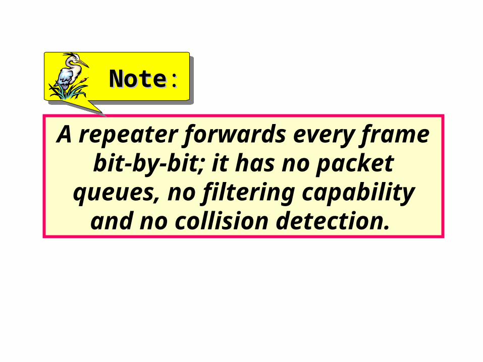
Spanning Tree - Example
B1B1
B2B2
1
• Networks are graph nodes, ports are graph edges• A spanning tree is a connected graph which has no loops (cycles)• The dotted links are the blocked ports on the bridge, in order to prevent
loops and duplicated frames
Network 1 Network 2
Network 3Network 4
B1
B2
1 2 3 4
The networkThe corresponding graph

Another example
B3
B5
B7B2
B1
B6 B4
B8
Cost for each
port is 1
(hop-count)

The Root Bridge and the Spanning Tree
B3
B5
B7B2
B1
B6 B4
Root
B8
B2 B4 B5 B7
B8
B1
Spanning Tree:
*
*
*
*
*
*
**
**
**
**
**
**** **
**
***
**A spanning tree is a connected graph which has no loops (cycles)
**

Multiple LANs with Bridges with Costs Assigned
B1
B6
B5B2 B3
B4
LAN 1
LAN 2
LAN 3
LAN 4
Cost=6
Cost=5Cost=4
Cost=1
Cost=6
Cost=5
Cost=4
Cost=2
Cost=6
Cost=4
L1L1
L2L2 L3L3
L4L4
B1B1
B2B2
B6B6B5B5
B4B4
B3B3
4
2
46
5
3Cost=2
Cost=3
6
4 5
6
1
The cost of sending from L1 to L4 via B1 and B2 is 6Only costs for going from a bridge to a LAN are added
2

Example: Root Bridge and Root Ports
• Lowest cost from each bridge to the root bridge are calculated.
• The root bridge and root ports are marked in red
L1L1
L2L2 L3L3
L4L4
B1B1
B2B2
B6B6B5B5
B4B4
B3B3
4
2
46
5
3
6
4 5
6
1
2
Cost=6
Cost=8Cost=2
Cost=6 Cost=3
Root

Example: Designated Ports and the Spanning Tree
L1L1
L2L2 L3L3
L4L4
B1B1
B2B2
B6B6B5B5
B4B4
B3B3
4
2
46
5
3
6
4 5
6
1
2
Cost=2L3
Cost=6 Cost=3
RootL1L2
Cost=6L4
Cost=8
*
*
*
*
* • Lowest cost from each LAN to the root bridge are calculated (= the cost from an adjacent bridge.)
• The designated ports are marked “*”.

Example: Designated Ports and the Spanning Tree
L1L1
L2L2 L3L3
L4L4
B1B1
B2B2
B6B6B5B5
B4B4
B3B3
4
2
3
6
4
2
The rest ofthe ports areblocked.
This results ina spanningtree.

Figure 16.13 Connecting remote LANs
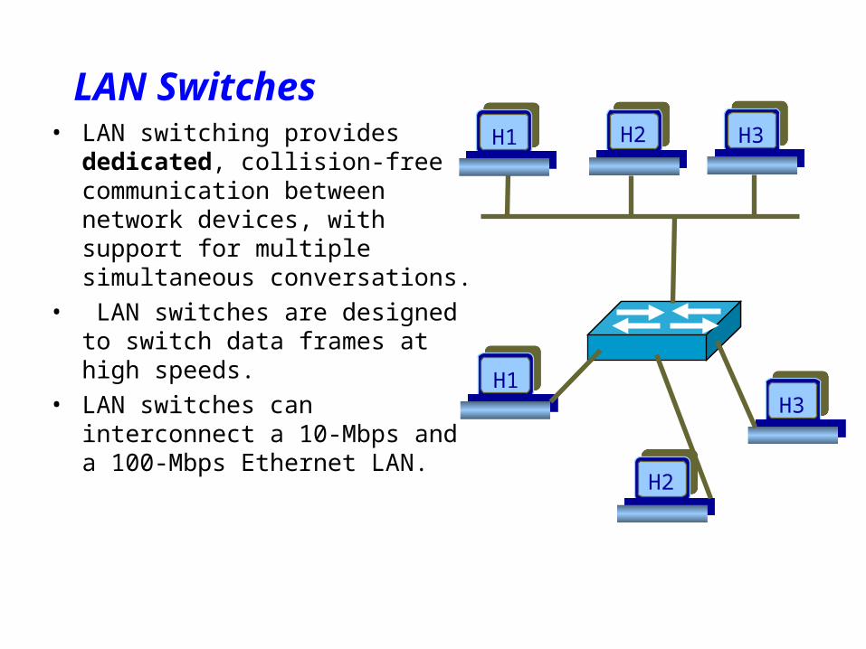
LAN Switches• LAN switching provides dedicated,
collision-free communication between network devices, with support for multiple simultaneous conversations.
• LAN switches are designed to switch data frames at high speeds.
• LAN switches can interconnect a 10-Mbps and a 100-Mbps Ethernet LAN.
H1 H2 H3
H1
H2
H3

A LAN Switch
• The computer has a segment to itself – the segment is busy only when a frame is being transfered to or from the computer
• As a result, as many as one-half of the computers connected to a switch can send data at the same time

Figure 16.12 Star backbone

16.3 Virtual LANs16.3 Virtual LANs
Membership
Configuration
IEEE Standard
Advantages

Figure 16.15 A switch using VLAN software

VLANs create broadcast domains.
NoteNote::
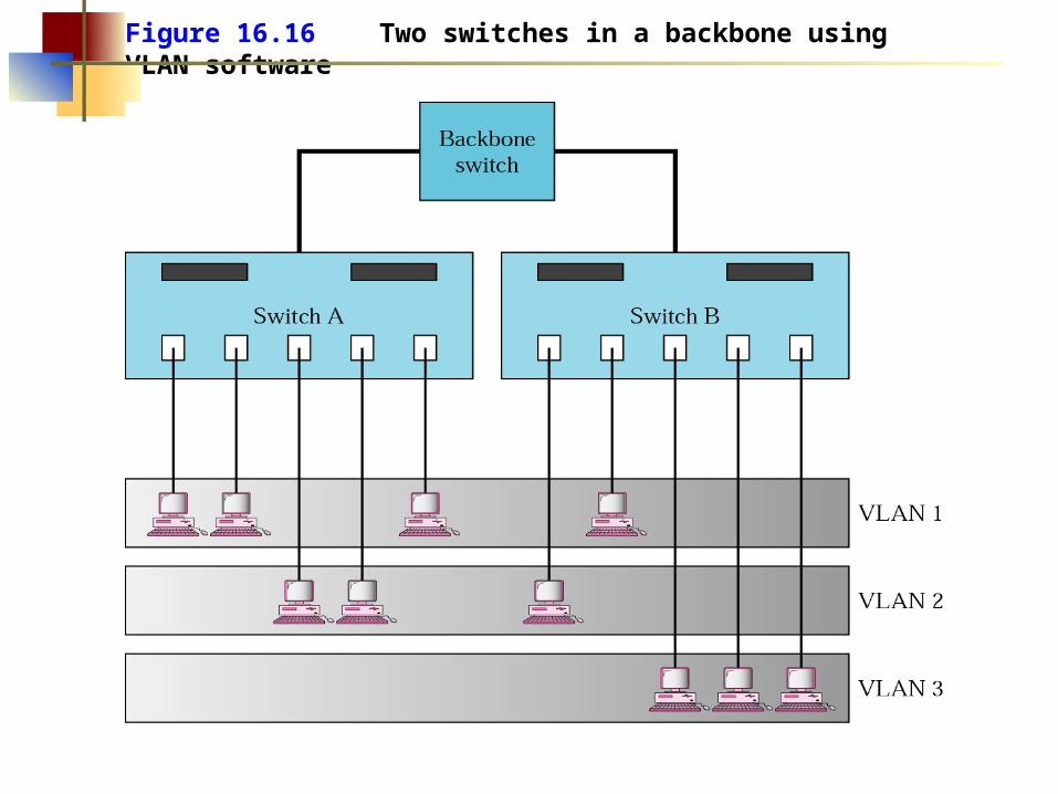
Figure 16.16 Two switches in a backbone using VLAN software

Chapter 18
Virtual CircuitSwitching:Frame Relay
andATM
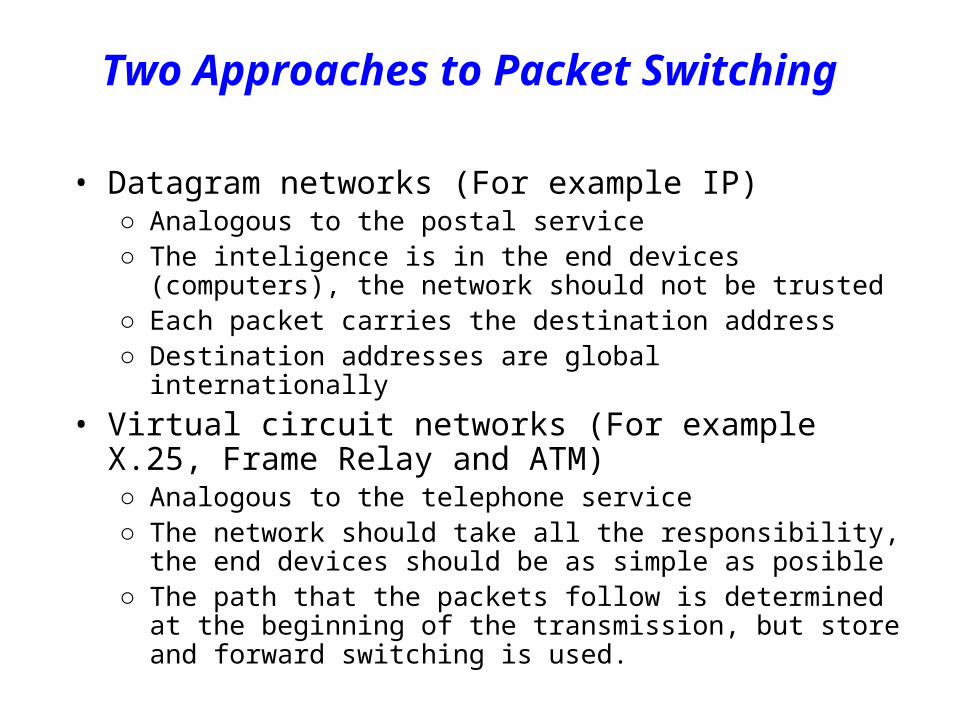
Two Approaches to Packet Switching
• Datagram networks (For example IP)○ Analogous to the postal service○ The inteligence is in the end devices (computers), the network should
not be trusted○ Each packet carries the destination address○ Destination addresses are global internationally
• Virtual circuit networks (For example X.25, Frame Relay and ATM)○ Analogous to the telephone service○ The network should take all the responsibility, the end devices should
be as simple as posible○ The path that the packets follow is determined at the beginning of the
transmission, but store and forward switching is used.

Characteristics of WANsCircuit Datagram Virtual Circuit
Dedicated path No dedicated path No dedicated pathContinuous datatransmission
Packets Packets
No data storage Store and forward Store and forwardConnectionestablished forentire conversation
Route establishedfor every packet
Route establishedfor every packet
Call setup delay;low transmissiondelay
Packet transmissiondelay
Call setup delay;Packet transmissiondelay
Busy signal Possible notificationof no/bad deliveries
Notification ofconnection denial
Blocking at networkoverload
Delay at networkoverload
Blocking/delay atnetwork overload
Fixed bandwidth Dynamic bandwidth Dynamic bandwidth
No overhead/data Overhead/packet Overhead/packet

Figure 18.1 Virtual circuit wide area network

Figure 18.3 VCI phases

Virtual Circuit Network
• Three Phases○ Setup phase
• Network protocol establishes a logical path called virtual circuit (VC). The path remains the same during transmission (all packets use it)
○ Data transfer phase
• Each packet carries “tag” or “label” (virtual circuit id, VCI), which determines next hop (the link to which the packet should be forwarded).
• At each node, the forwarding is done by inspecting the input line, the VCI and consulting the forwarding table at the switches.
○ Teardown phase
• All switches remove the entries about the VCI from their tables

Figure 18.2 VCI

Figure 18.4 Switch and table

X.25 Networks
• Developed in 1970s in European countries under the auspices of ITU○ Public packet-switched networks ○ Uses virtual circuit connections
• Switched virtual circuits – analog to dial-up in circuit switching• Permanent virtual circuits – analog to leased lines in circuit
switching.○ Operates on the three lowest layers (physical, data-link and network layer)○ Performs error-contol and flow-control on the node-to-node basis○ Work at speed up to 64Kbps○ Nowadays it is obsolete

Frame Relay• X.25 data rates were not stisfactory for users looking for higher data
rates and lower costs○ Checking frames for error at every node is inefficient
○ Only one fourth of traffic is message traffic, the rest is overhead (necessary for transmission media that are more error prone)
• Frame relay – public data network that have improved performance○ Developed having in mind new transmission media that have much lower
probability of error
○ Does not provide error checking and acknowledgement at both, the data-link layer and the network layer

X.25 versus Frame Relay
Data
Frame ackData
Frame ack
Data
Frame ackData
Frame ack
Ack Ack Ack Ack
Data Data Data Data
X.25 traffic (ACKs at both data-link and transport layer)
Frame relay traffic (ACKs are required at the transport layer only)
switch switch switch

Frame Relay in the Internet
• The virtual circuits in frame-relay are called DLCI (Data Link Connection Identifier)
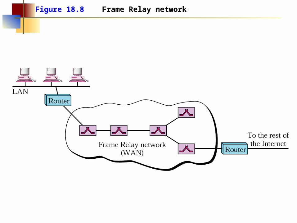
Figure 18.8 Frame Relay network

Frame Relay operates only at the physical and data link layers.
NoteNote::

Frame Relay does not provide flow or error control; they must be provided by
the upper-layer protocols.
NoteNote::

ATM – Basic Idea• Uses small fixed-size packets called cells
○ The cells are 53 bytes long (48 bytes payload + 5 bytes header)○ The length of the cell compromise between American and European
telephone companies (average of 32 and 64)
• Uses packet switching○ Connection oriented (uses virtual circuits)
• Speeds of 155 Mbps or 622 Mbps are achieved over SONET• Was heavily promoted by telephone companies as BISDN
(Broadband Integrated Services Digital Network) technology.

Figure 18.13 Multiplexing using different frame sizes

Figure 18.14 Multiplexing using cells

A cell network uses the cell as the basic unit of data exchange. A cell is
defined as a small, fixed-sized block of information.
NoteNote::

ATM Basic Concepts• Nagotiated Service Contract
○ Logical connections called Virtual circuits
• The sender nagotiates a ”requested path” with the network for a connection to the destination
○ End-to-end Quality of Service
• When setting up a connection the sender specifies the atributes of the call (type, sped, ...) which determine end-to-end quality of service
• Virtual Circuit Network○ Well defined connection procedures○ Dedicated capacity per connection○ Flexible access speeds
• Cell based (short packets with fixed size)• All kinds of data look same to the network

ATM Switching
• When a site has an information to send to another, it requests a connection by sending a message
• The message passes through vasious switches, setting up a virtual path
End System B
End System A
Connect to BConnect to B
Connect to B
Connect to B
OK
OK
OK
OK
Subsequent data cells contain a virtual path ID which the switch uses to to route the cell through outgoing links
Using the input port and VP ID, the switch locates the table entry, changes the cell VP ID with one paired with the asssociated output port and sends the cell through that port

Virtual Circuit and Paths
Virtual Path (VP)
Virtual Path (VP)
ATM Physical Link(STM-1, OC-12, E1)
Virtual Channel Connection (VCC)
Virtual Circuits (VC)
Virtual Circuit (VC)= Logical Path between
ATM End PointsVCC - contains multiple VPs
VP - contains multiple VC
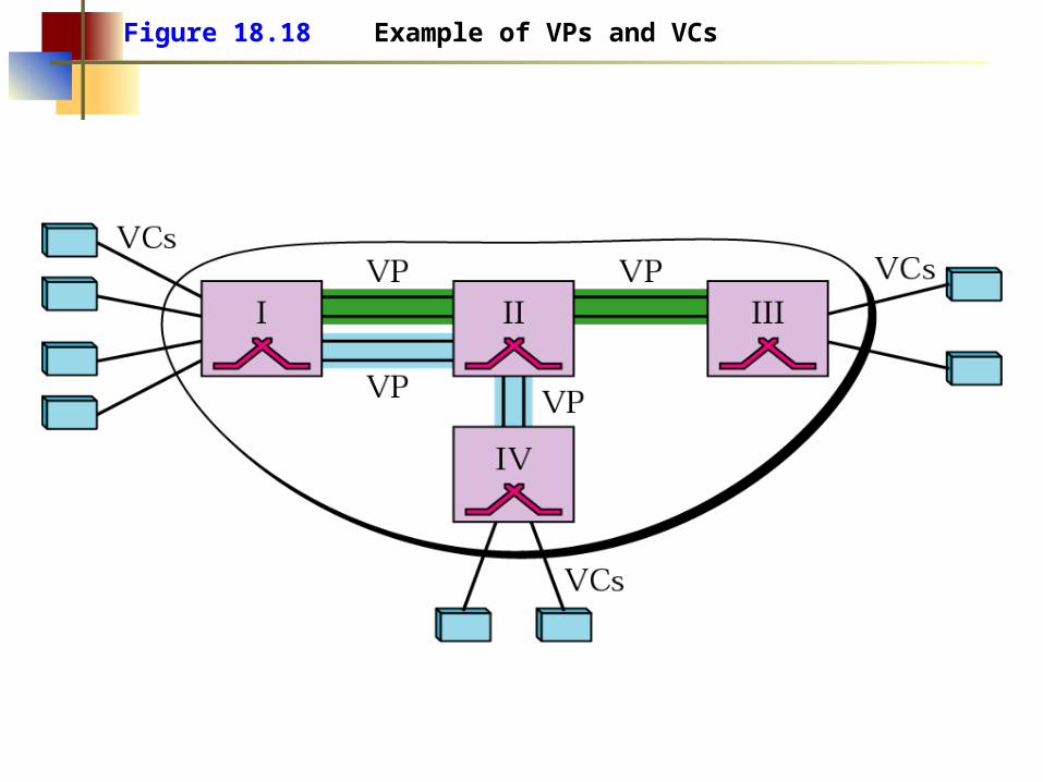
Figure 18.18 Example of VPs and VCs

Note that a virtual connection is defined by a pair of numbers:
the VPI and the VCI.
NoteNote::

Figure 18.19 Connection identifiers

Figure 18.20 Virtual connection identifiers in UNIs and NNIs

Figure 18.21 An ATM cell

Figure 18.22 Routing with a switch

ATM Service Models
• CBR (Constant Bit Rate)○ Carries real time (constant bit rate) traffic○ Guaranties rate, delay and loss of cells
• UBR (Unspecified Bit Rate)○ No other guarantee besides in-order delivery of cells
• ABR (Available Bit Rate)○ No guarantee on transmision rate, but if possible the user can use a higher
rate than in UBR.○ Congestion feedback from the network
• VBR○ The variable bit-rate is requested by the sender○ Targeted toward real-time services like CBR