Embed Size (px)
Citation preview
Skyworks Solutions, Inc. • Phone [781] 376-3000 • Fax [781] 376-3100 • [email protected] • www.skyworksinc.com 202412I • Skyworks Proprietary Information • Products and Product Information are Subject to Change Without Notice • October 14, 2016 1
DATA SHEET
SE2435L: 860 to 930 MHz High-Power RF Front-End Module Applications
Internet of Things
Smart meters
In-home appliances
Smart thermostats
Industrial applications
Features
Integrated PA with +30 dBm output power
Integrated LNA with programmable bypass
Integrated antenna switching with transmit/receive diversity function
Low FEM noise figure of 2 dB, typical
Single-ended 50 transmit/receive RF interface
Fast turn-on/turn-off time: < 1 μsec
Supply voltage: 2.0 to 4.8 V
Sleep mode current: < 1 μA
QFN (24-pin, 4 x 4 x 0.9 mm ) NiPdAu plated package (MSL1, 260 C per JEDEC J-STD-020)
Skyworks GreenTM products are compliant withall applicable legislation and are halogen-free.For additional information, refer to SkyworksDefinition of GreenTM, document number SQ04–0074.
N/C
18
15
17
16
14
13
1
4
2
3
5
6
24 2123 22 20 19
7 10
8 9 11
12
N/C
TX_FLT
CSD
TR
PA_IN
CPS
CTX N/C
N/C
ANT1
TX_IN
Y0083
VCC1
VCC0
N/C
VCC2
PA_O
UT
N/C
ANT_
SEL
GND
LNA_
IN
N/C
RX_F
LT
ANT2
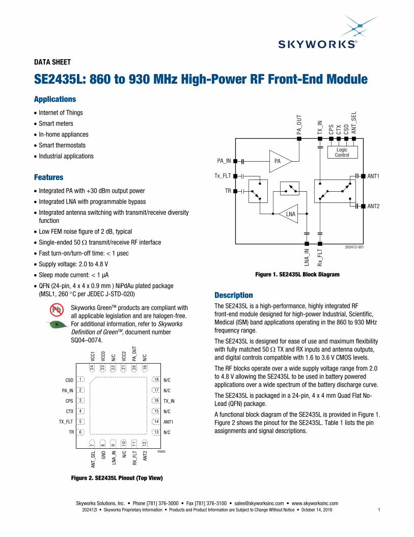
Figure 2. SE2435L Pinout (Top View)
PA
LNA
TR
ANT1
ANT2
LNA_
IN
Rx_
FLT
PA_IN
Tx_FLT
CPS
CSD
CTX
LogicControl
ANT_
SEL
PA_O
UT
TX_I
N
202412-001
Figure 1. SE2435L Block Diagram
Description The SE2435L is a high-performance, highly integrated RF front-end module designed for high-power Industrial, Scientific, Medical (ISM) band applications operating in the 860 to 930 MHz frequency range.
The SE2435L is designed for ease of use and maximum flexibility with fully matched 50 TX and RX inputs and antenna outputs, and digital controls compatible with 1.6 to 3.6 V CMOS levels.
The RF blocks operate over a wide supply voltage range from 2.0 to 4.8 V allowing the SE2435L to be used in battery powered applications over a wide spectrum of the battery discharge curve.
The SE2435L is packaged in a 24-pin, 4 x 4 mm Quad Flat No-Lead (QFN) package.
A functional block diagram of the SE2435L is provided in Figure 1. Figure 2 shows the pinout for the SE2435L. Table 1 lists the pin assignments and signal descriptions.

DATA SHEET • SE2435L: 860 TO 930 MHz HIGH-POWER RF FRONT-END MODULE
Skyworks Solutions, Inc. • Phone [781] 376-3000 • Fax [781] 376-3100 • [email protected] • www.skyworksinc.com 2 October 14, 2016 • Skyworks Proprietary Information • Products and Product Information are Subject to Change Without Notice • 202412I
Table 1. SE2435L Signal Descriptions
Pin Name Description Pin Name Description
1 CSD Shutdown control input 14 ANT1 Antenna port 1
2 PA_IN PA input (from Tx filter) 15 N/C Not connected internally to the device
3 CPS Rx path select control input 16 TX_IN Tx signal to antennas (from OMN)
4 CTX Transmit enable control input 17 N/C Not connected internally to the device
5 TX_FLT Transmit signal (to Tx filter) 18 N/C Not connected internally to the device
6 TR Bi-directional RF signal to/from transceiver 19 N/C Not connected internally to the device
7 ANT_SEL Antenna select control input 20 PA_OUT PA output (to Z optimum)1
8 GND Ground 21 VCC2 Positive power supply
9 LNA_IN LNA input (from Rx filter) 22 N/C Not connected internally to the device
10 N/C Not connected internally to the device 23 VCC0 Positive power supply
11 RX_FLT Rx signal from antennas (to Rx filter) 24 VCC1 Positive power supply
12 ANT2 Antenna port 2 Paddle GND
Exposed die paddle; electrical and thermal ground. Connect to PCB ground 13 N/C Not connected internally to the device
1 Z optimum = 5 Ω for +30 dBm or 8 Ω for +27 dBm POUT.
Electrical and Mechanical Specifications Table 2 provides the absolute maximum ratings, and Table 3 shows the recommended operating conditions.
Electrical specifications are provided in Tables 4 through 9. Typical performance characteristics are shown in Figures 3 through 8.
Table 2. SE2435L Absolute Maximum Ratings1
Parameter Symbol Minimum Maximum Units
Supply voltage (no RF) VCC –0.3 5.5 V
Operating temperature TA –40 85 °C
Storage temperature TSTG –40 125 °C
Tx input power at TR port PIN_TX_MAX +10 dBm
Rx input power at ANT1 or ANT2 ports PIN_RX_MAX +10 dBm
Electrostatic discharge:
Human Body Model (HBM), Class 1C
ESD
1000
V 1 Exposure to maximum rating conditions for extended periods may reduce device reliability. There is no damage to device with only one parameter set at the limit and all other parameters
set at or below their nominal value. Exceeding any of the limits listed here may result in permanent damage to the device.
ESD HANDLING: Although this device is designed to be as robust as possible, electrostatic discharge (ESD) can damage this device. This device must be protected at all times from ESD when handling or transporting. Static charges may easily produce potentials of several kilovolts on the human body or equipment, which can discharge without detection. Industry-standard ESD handling precautions should be used at all times.

DATA SHEET • SE2435L: 860 TO 930 MHz HIGH-POWER RF FRONT-END MODULE
Skyworks Solutions, Inc. • Phone [781] 376-3000 • Fax [781] 376-3100 • [email protected] • www.skyworksinc.com 202412I • Skyworks Proprietary Information • Products and Product Information are Subject to Change Without Notice • October 14, 2016 3
Table 3. SE2435L Recommended Operating Conditions
Parameter Symbol Minimum Typical Maximum Units
Supply voltage on VCC VCC 2.0 4.0 4.8 V
Ambient temperature TA –40 +25 +85 °C
Table 4. SE2435L DC Electrical Specifications1 (VCC = 4.0 V, f = 915 MHz, TA = +25 C, Unless Otherwise Noted)
Parameter Symbol Test Condition Min Typical Max Units
Total supply current, transmit mode ICC_TX30 ICC_TX27 ICC_TX24
POUT = +30 dBm POUT = +27 dBm POUT = +24 dBm
550 380 275
mA mA mA
Total supply current, receive mode ICC_RX 6 mA
Total supply current, receive bypass mode ICC_RXB 280
μA
Quiescent current ICQ_TX No RF 50 mA
Sleep supply current ICC_OFF No RF 0.05 1.00 μA 1 Performance is guaranteed only under the conditions listed in this table.
Table 5. SE2435L Electrical Specifications: Control Logic Characteristics1 (TA = +25 C, Unless Otherwise Noted)
Parameter Symbol Test Condition Min Typical Max Units
Control voltage: High Low
VIH VIL
1.6 0
Vcc (Note 2)
0.3
V V
Input current: High Low
IIH IIL
1 1
μA μA
1 Performance is guaranteed only under the conditions listed in this table.
2 For Pin 7, ANT_SEL, the maximum is 3.6 V.
Table 6. SE2435L Electrical Specifications: Mode Control Logic (TA = +25)
Mode CPS CSD CTX ANT_SEL
Sleep (all off) 0 0 0 X
Receive or transmit bypass 0 1 0 X
Receive LNA mode 1 1 0 X
Transmit X 1 1 X
ANT1 port enabled X X X 0
ANT2 port enabled X X X 1 1 “1” = 1.6 to Vcc, “0” = 0 to 0.3 V, “X” = don’t care.

DATA SHEET • SE2435L: 860 TO 930 MHz HIGH-POWER RF FRONT-END MODULE
Skyworks Solutions, Inc. • Phone [781] 376-3000 • Fax [781] 376-3100 • [email protected] • www.skyworksinc.com 4 October 14, 2016 • Skyworks Proprietary Information • Products and Product Information are Subject to Change Without Notice • 202412I
Table 7. SE2435L Electrical Specifications: AC Transmit Mode (VCC = 4 V, TA = +25 C, All Unused Ports Terminated at 50 , Unless Otherwise Noted. Input Port TR, Output Ports ANT1 and ANT2 Lumped Elements Filter Connected between the TX_FLT and PA_IN Pins)
Parameter Symbol Test Condition Min Typical Max Units
Frequency range f 860 930 MHz
Output power at ANT1 or ANT2 ports in the 900 to 930 MHz frequency range1
POUT_915 VCC = 4.8 V VCC = 4.0 V VCC = 3.6 V VCC = 3.0 V
+31.5 +30.5 +29.5 +28.0
dBm dBm dBm dBm
Output power at ANT1 or ANT2 ports in the 860 to 870 MHz frequency range2
POUT_860 VCC = 4.0 V VCC = 3.6 V VCC = 3.0 V VCC = 2.0 V
+27 +24 +21 +18
dBm dBm dBm dBm
PA power added efficiency PAE_PA POUT = +28 dBm at PA_OUT port, 915 MHz
64
%
Small signal gain1 S21_915 900 to 930 MHz 26 dB
Small signal gain2 S21_860 860 to 870 MHz 26 dB
Small signal gain variation1, 2 S21 Gain variation across frequency range
2
dBp-p
Output return loss1, 2 S22ANT1,2 Into 50 , ANT1 and ANT2 ports
–10
–6
dB
2nd harmonic1, 3 2fo POUT = +30 dBm –22 dBc
3rd to 10th harmonic1, 3 3fo to 10fo POUT = +30 dBm –72 dBc
Turn-on time4 tON 1 μs
Turn-off time tOFF 1 μs
Stability STAB CW, PIN = 0 dBm 0.1 GHz to 20 GHz load VSWR = 6:1
All non-harmonically related outputs less than –43 dBm
Ruggedness RU CW, POUT = +30 dBm into 50 Ω, load VSWR = 10:1
No permanent damage
1 900 to 930 MHz with specified matching network on the Evaluation Board. 2 860 to 870 MHz with specified matching network on the Evaluation Board. 3 Measured with continuous wave signal. 4 From 50% of CTX edge to 90% of final RF output power.

DATA SHEET • SE2435L: 860 TO 930 MHz HIGH-POWER RF FRONT-END MODULE
Skyworks Solutions, Inc. • Phone [781] 376-3000 • Fax [781] 376-3100 • [email protected] • www.skyworksinc.com 202412I • Skyworks Proprietary Information • Products and Product Information are Subject to Change Without Notice • October 14, 2016 5
Table 8. SE2435L Electrical Specifications: AC Receive Mode (VCC = 4 V, TA = +25 C, f = 900 to 930 MHz and 860 to 870 MHz, All Unused Ports Terminated at 50 Ω, Unless Otherwise Noted. Input Port ANT1 or ANT2, Output Port TR. 0 Ω Connected between the RX_FLT and LNA_IN Pins in lieu of External Filters)
Parameter Symbol Test Condition Min Typical Max Units
Frequency range fIN 860 930 MHz
Receive gain RX_GAIN 14 16 18 dB
Receive noise figure NF 2 2.5 dB
Input third order intercept IIP3 –5 –2 dBm
Input 1-dB compression point IP1dB –15 –12 dBm
Antenna port return loss S11ANT1,2 Into 50 , ANT1 and ANT2 ports –12 –8 dB
Turn-on time1 tON 1 μs
Turn-off time2 tOFF 1 μs
Gain in bypass mode G_bp –3 –2 dB
Input 1-dB compression point in bypass mode IP1dB +10 dBm 1 From 50% of CTX edge to 90% of final RF output power. 2 From 50% of CTX edge to 10% of final RF output power.
Table 9. SE2435L DC Electrical Specifications: Diversity Antenna Function (VCC = 4 V, TA = +25 C, f = 900 to 930 MHz and 860 to 870 MHz, All Unused Ports Terminated at 50 , Unless Otherwise Noted)
Parameter Symbol Min Typical Max Units
Isolation between ANT1 and ANT2 ports ISOLANTSW –20 dB
Insertion loss from TX_IN to ANT1 TX_ANT1 0.8 dB
Insertion loss from TX_IN to ANT2 TX_ANT2 0.8 dB
Insertion loss from ANT1 to RX_FLT RX_ANT1 0.6 dB
Insertion loss from ANT2 to RX_FLT RX_ANT2 0.6 dB
Insertion loss from TR to TX_FLT TxRx_Tx 0.5 dB
ANT1 to ANT2 switching time transmit mode TANT1-ANT1_TX 800 ns
ANT1 to ANT2 switching time receive mode TANT1-ANT2_RX 400 ns

DATA SHEET • SE2435L: 860 TO 930 MHz HIGH-POWER RF FRONT-END MODULE
Skyworks Solutions, Inc. • Phone [781] 376-3000 • Fax [781] 376-3100 • [email protected] • www.skyworksinc.com 6 October 14, 2016 • Skyworks Proprietary Information • Products and Product Information are Subject to Change Without Notice • 202412I
Typical Performance Characteristics (Note 1) (VCC = 4 V, TA = +25 C, f = 900 to 930 MHz, All Unused Ports Terminated at 50 , Unless Otherwise Noted)
–120
–110
–100
–90
–80
–70
–60
–50
–40
–30
–20
#2 #3 #4 #5 #6 #7 #8 #9 #10
Leve
l (dB
c)
# Harmonics
2024
12-0
03
900 MHz
915 MHz930 MHz
Figure 3. Typical Harmonics Level at +30 dBm POUT (including Antenna Filter)
20
22
24
26
28
30
32
34
+10 +12 +14 +16 +18 +20 +22 +24 +26 +28 +30 +32
2024
12-0
05
Gain
(dB)
Output Power (dBm)
900 MHz915 MHz930 MHz
Figure 5. Typical Gain vs POUT (VCC = 4 V)
2024
12-0
07
+10 +12 +14 +16 +18 +20 +22 +24 +26 +28 +30 +32
Output Power (dBm)
20
22
24
26
28
30
32
34
Gain
(dB)
+34
2.0 V3.3 V3.6 V4.0 V4.8 V
Figure 7. Typical Gain vs POUT (VCC = 2.0 to 4.8 V)
50
150
250
350
450
550
650
+5
+10
+15
+20
+25
+30
+35
–22 –20 –18 –16 –14 –12 –10 –8 –6 –4 –2 0 +2 +4 +6
ICC
(mA)
P OUT
(dBm
)
Input Power (dBm)
Pout [dBm]
ICC [mA]
202412-004
Figure 4. Typical POUT and ICC Transfer Characteristics
2024
12-0
06
50
150
250
350
450
550
650
+10 +12 +14 +16 +18 +20 +22 +24 +26 +28 +30 +32
ICC
(mA)
Output Power (dBm)
900 MHz
915 MHz
930 MHz
Figure 6. Typical ICC vs POUT (VCC = 4 V)
30
35
40
45
50
55
+20 +21 +22 +23 +24 +25 +26 +27 +28 +29 +30 +31 +32 +33 +34
PAE
(%)
2024
12-0
08
Output Power (dBm)
3.3 V3.6 V4.0 V4.8 V
2.0 V
Figure 8. Typical PAE vs POUT & VCC, CW (VCC = 2.0 to 4.8 V)
(including OMN and Antenna Filter Losses)
Note: Typical performance graphs at 868 MHz are available upon request (+24, +27, and +30 dBm POUT).
DATA SHEET • SE2435L: 860 TO 930 MHz HIGH-POWER RF FRONT-END MODULE
Skyworks Solutions, Inc. • Phone [781] 376-3000 • Fax [781] 376-3100 • [email protected] • www.skyworksinc.com 202412I • Skyworks Proprietary Information • Products and Product Information are Subject to Change Without Notice • October 14, 2016 7
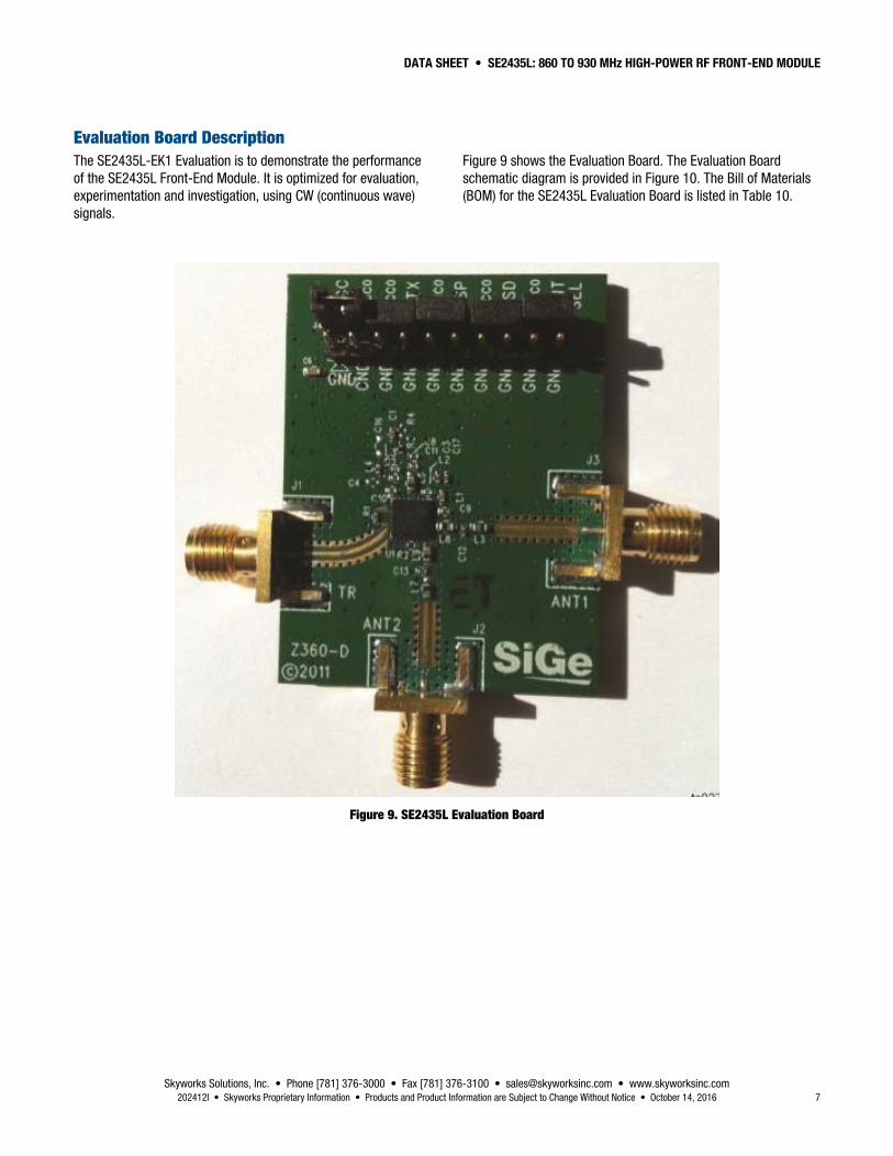
Evaluation Board Description The SE2435L-EK1 Evaluation is to demonstrate the performance of the SE2435L Front-End Module. It is optimized for evaluation, experimentation and investigation, using CW (continuous wave) signals.
Figure 9 shows the Evaluation Board. The Evaluation Board schematic diagram is provided in Figure 10. The Bill of Materials (BOM) for the SE2435L Evaluation Board is listed in Table 10.
Figure 9. SE2435L Evaluation Board

DATA SHEET • SE2435L: 860 TO 930 MHz HIGH-POWER RF FRONT-END MODULE
Skyworks Solutions, Inc. • Phone [781] 376-3000 • Fax [781] 376-3100 • [email protected] • www.skyworksinc.com 8 October 14, 2016 • Skyworks Proprietary Information • Products and Product Information are Subject to Change Without Notice • 202412I
× ×
C110 nF C11
1 nFC833 pF
C222 pF
C10100 pF
R13.3 pF
L43.3 nH
L34.7 nH
L5
L2
L8 L6
6.8 nH
6.8 nH 6.8 nH
L9 L76.8 nH 6.8 nH
1.3 nHC3
8.2pF
C171.8 pF
C93.3 pF
C123.3 pF
L13.0 nH
C133.3 pF
C64.7 µF
CSD
CPS CPS
CTX
TR
CTX
ANT_SEL
J3
J4
J1
J2
SMA
SMA
SMA
CSD N/C
N/C
N/C
ANT1
N/C
PA_IN
TX_FLT
TX_IN
ANT_
SEL
GND
N/C
RX_F
LT
ANT2
LNA_
IN
PAD
VCC1 N/C
N/C
VCC2
PA_O
UT
VCC0
1
2
3
4
5
6
18
17
16
15
14
13
7 8 9 10 11 12
25 24 23 22 21 20 19
U1SE2435L
VCC
VDD
CTX
CPS
CSD
ANT_SEL
1
3
5
7
9
11
13
15
17
19
2
4
6
8
10
12
14
16
18
20
202412-010Note: Discard N/C pins that are connected to ground on the Evaluation Board.
××
×
×
×
Figure 10. Evaluation Board Schematic for 915 MHz Application and FCC Conducted Harmonics Rejection Compliant
DATA SHEET • SE2435L: 860 TO 930 MHz HIGH-POWER RF FRONT-END MODULE
Skyworks Solutions, Inc. • Phone [781] 376-3000 • Fax [781] 376-3100 • [email protected] • www.skyworksinc.com 202412I • Skyworks Proprietary Information • Products and Product Information are Subject to Change Without Notice • October 14, 2016 9
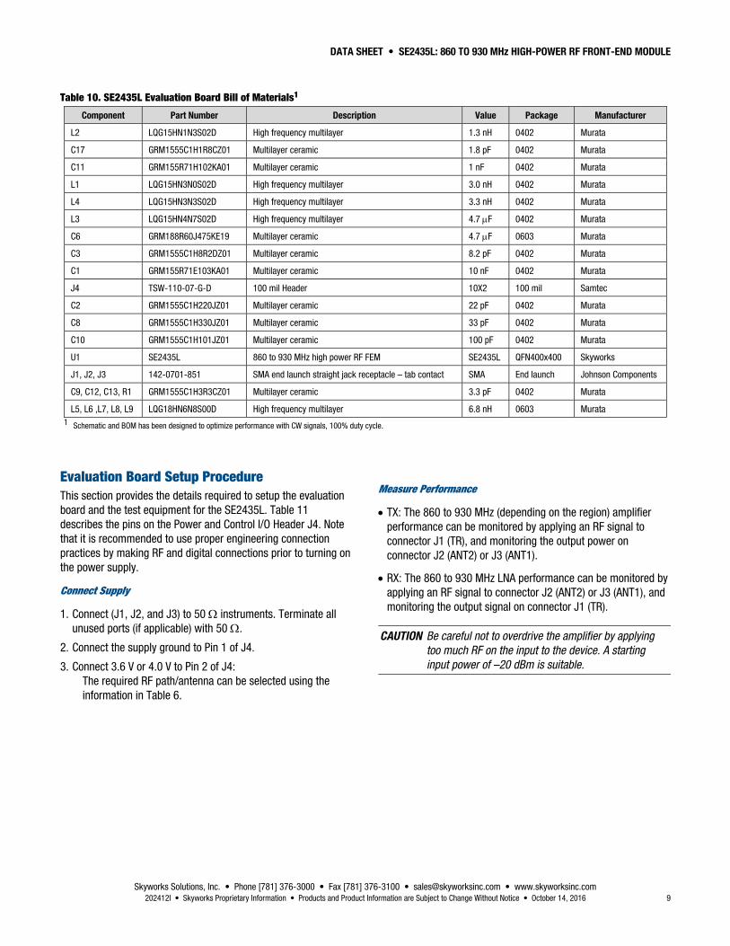
Table 10. SE2435L Evaluation Board Bill of Materials1
Component Part Number Description Value Package Manufacturer
L2 LQG15HN1N3S02D High frequency multilayer 1.3 nH 0402 Murata
C17 GRM1555C1H1R8CZ01 Multilayer ceramic 1.8 pF 0402 Murata
C11 GRM155R71H102KA01 Multilayer ceramic 1 nF 0402 Murata
L1 LQG15HN3N0S02D High frequency multilayer 3.0 nH 0402 Murata
L4 LQG15HN3N3S02D High frequency multilayer 3.3 nH 0402 Murata
L3 LQG15HN4N7S02D High frequency multilayer 4.7 F 0402 Murata
C6 GRM188R60J475KE19 Multilayer ceramic 4.7 F 0603 Murata
C3 GRM1555C1H8R2DZ01 Multilayer ceramic 8.2 pF 0402 Murata
C1 GRM155R71E103KA01 Multilayer ceramic 10 nF 0402 Murata
J4 TSW-110-07-G-D 100 mil Header 10X2 100 mil Samtec
C2 GRM1555C1H220JZ01 Multilayer ceramic 22 pF 0402 Murata
C8 GRM1555C1H330JZ01 Multilayer ceramic 33 pF 0402 Murata
C10 GRM1555C1H101JZ01 Multilayer ceramic 100 pF 0402 Murata
U1 SE2435L 860 to 930 MHz high power RF FEM SE2435L QFN400x400 Skyworks
J1, J2, J3 142-0701-851 SMA end launch straight jack receptacle – tab contact SMA End launch Johnson Components
C9, C12, C13, R1 GRM1555C1H3R3CZ01 Multilayer ceramic 3.3 pF 0402 Murata
L5, L6 ,L7, L8, L9 LQG18HN6N8S00D High frequency multilayer 6.8 nH 0603 Murata 1 Schematic and BOM has been designed to optimize performance with CW signals, 100% duty cycle.
Evaluation Board Setup Procedure This section provides the details required to setup the evaluation board and the test equipment for the SE2435L. Table 11 describes the pins on the Power and Control I/O Header J4. Note that it is recommended to use proper engineering connection practices by making RF and digital connections prior to turning on the power supply.
Connect Supply
1. Connect (J1, J2, and J3) to 50 instruments. Terminate all unused ports (if applicable) with 50 .
2. Connect the supply ground to Pin 1 of J4.
3. Connect 3.6 V or 4.0 V to Pin 2 of J4: The required RF path/antenna can be selected using the information in Table 6.
Measure Performance
TX: The 860 to 930 MHz (depending on the region) amplifier performance can be monitored by applying an RF signal to connector J1 (TR), and monitoring the output power on connector J2 (ANT2) or J3 (ANT1).
RX: The 860 to 930 MHz LNA performance can be monitored by applying an RF signal to connector J2 (ANT2) or J3 (ANT1), and monitoring the output signal on connector J1 (TR).
CAUTION Be careful not to overdrive the amplifier by applying too much RF on the input to the device. A starting input power of –20 dBm is suitable.

DATA SHEET • SE2435L: 860 TO 930 MHz HIGH-POWER RF FRONT-END MODULE
Skyworks Solutions, Inc. • Phone [781] 376-3000 • Fax [781] 376-3100 • [email protected] • www.skyworksinc.com 10 October 14, 2016 • Skyworks Proprietary Information • Products and Product Information are Subject to Change Without Notice • 202412I
Table 11. Power and Control I/O Header (J4)
Evaluation Board Label Pin Number Description Recommended setting
GND 1,3,5,7,9,11,13,15,17,19 Ground General purpose grounds
VCC 2,4,6,10,14,18 Supply voltage General purpose VCC provided as the main power supply.
CTX 8 Control
See Table 6. CPS 12 Control
CSD 16 Control
ANTSEL 20 Control
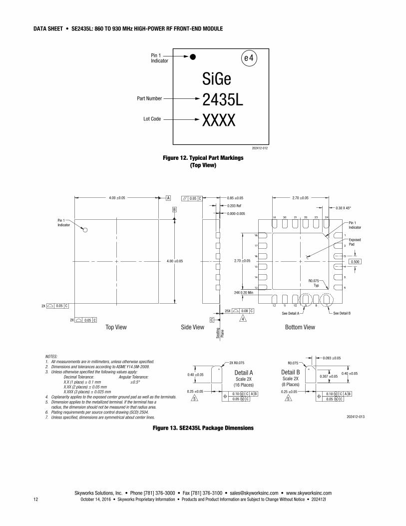
Package Dimensions The layout footprint for the SE2435L is provided in Figure 11. Typical part markings are shown in Figure 12. Package dimensions for the SE2435L are shown in Figure 13, and tape and reel dimensions are provided in Figure 14.
Package and Handling Information Instructions on the shipping container label regarding exposure to moisture after the container seal is broken must be followed. Otherwise, problems related to moisture absorption may occur when the part is subjected to high temperature during solder assembly.
The SE2435L is rated to Moisture Sensitivity Level 1 (MSL1) at 260 C. It can be used for lead or lead-free soldering. For additional information, refer to the Skyworks Application Note, Solder Reflow Information, document number 200164.
Care must be taken when attaching this product, whether it is done manually or in a production solder reflow environment. Production quantities of this product are shipped in a standard tape and reel format.

DATA SHEET • SE2435L: 860 TO 930 MHZ HIGH-POWER RF FRONT-END MODULE
Skyworks Solutions, Inc. • Phone [781] 376-3000 • Fax [781] 376-3100 • [email protected] • www.skyworksinc.com 11 November 11, 2014 • Skyworks Proprietary Information • Products and Product Information are Subject to Change Without Notice • 202412G
Board Metal
4.40
0.500 Typ0.25 Typ
202412-011
5X 1.02
5X 0.51
5X 0.0
5X 0.51
5X 1.02
Solder Mask Pattern(Note 6)
4.402.70
0.60 Typ
4.502.50
4.50
2.50
0.500 Typ0.35 Typ
4 x 4 QFNPackage Outline
25X Ø0.254
5X 1
.02
5X 0
.51
5X 0
.0
5X 0
.51
5X 1
.02
0.500 Typ0.25 Typ
4.40
0.70 Typ 0.60 Typ
1.00 Typ
1.00 Typ
0.20 Typ
4.40
0.20 Typ
Stencil Pattern (Note 5)64% Solder Coverage
on Center Pad
0
Via Pattern (Note 4)
Notes:
1. All dimensions are in millimeters.2. Interpret dimensions and tolerances per ASME Y14.5M-1994.3. Unless specified, dimensions are symmetrical about center lines.4. Via hole recommendations: 0.025 mm Cu via wall plating (minimum), solder mask on the far side should tent or plug via holes.5. Stencil recommendations: 0.125 mm stencil thickness, laser cut apertures, trapezoidal walls and rounded corners offer the best paste release.6. Solder mask recommendations: Contact board fabricator for recommended solder mask offset and tolerance.
2.70
0
Figure 11. SE2435L Recommended Footprint (Top View)
DATA SHEET • SE2435L: 860 TO 930 MHz HIGH-POWER RF FRONT-END MODULE
Skyworks Solutions, Inc. • Phone [781] 376-3000 • Fax [781] 376-3100 • [email protected] • www.skyworksinc.com 12 October 14, 2016 • Skyworks Proprietary Information • Products and Product Information are Subject to Change Without Notice • 202412I
SiGe2435LXXXX
Part Number
Pin 1Indicator
Lot Code
e4
202412-012
Figure 12. Typical Part Markings (Top View)
Top View Side View
4.00 ±0.05
Pin 1Indicator
4.00 ±0.05
B
0.05 C
0.203 Ref
Seat
ing
Pla
ne
0.000-0.005
2.70 ±0.05
2.70 ±0.05
24X 0.20 Min
0.500
0.30 X 45°
A
0.05 C
0.05 C2X
2X
0.08 C25X
C 4
0.85 ±0.05
Pin 1Indicator
ExposedPad
See Detail BSee Detail A
R0.075Typ
0.05 C0.10 C A B
0.40 ±0.05
0.25 ±0.05
5
2X R0.075
0.05 C0.10 C A B
0.40 ±0.05
0.25 ±0.05
5
R0.0750.093 ±0.05
0.307 ±0.05
Bottom View
Detail AScale 2X
(16 Places)
Detail BScale 2X(8 Places)
202412-013
NOTES:1. All measurements are in millimeters, unless otherwise specified.2. Dimensions and tolerances according to ASME Y14.5M-2009.3. Unless otherwise specified the following values apply: Decimal Tolerance: Angular Tolerance: X.X (1 place) ± 0.1 mm ±0.5° X.XX (2 places) ± 0.05 mm X.XXX (3 places) ± 0.025 mm4. Coplanarity applies to the exposed center ground pad as well as the terminals.5. Dimension applies to the metallized terminal. If the terminal has a radius, the dimension should not be measured in that radius area.6. Plating requirements per source control drawing (SCD) 2504.7. Unless specified, dimensions are symmetrical about center lines.
Figure 13. SE2435L Package Dimensions

DATA SHEET • SE2435L: 860 TO 930 MHz HIGH-POWER RF FRONT-END MODULE
Skyworks Solutions, Inc. • Phone [781] 376-3000 • Fax [781] 376-3100 • [email protected] • www.skyworksinc.com 202412I • Skyworks Proprietary Information • Products and Product Information are Subject to Change Without Notice • October 14, 2016 13
Notes:
1. All dimensions are in millimeters. 2. Ten-sprocket hole pitch cumulative tolerance ±0.2 mm.3. Camber in compliance with EIA-481.
4.35 ±0.1
12.0 ±0.3
Pin 1 Indicator
4.35 ±0.1
1.75 ±0.1
8.0 ±0.1 D 1.50 +0.10
4.0 Note 1
0.254 ±0.0131.22 ±
0.1
2.0 ±0.05
5.5 ±0.05
202412-014
Figure 14. SE2435L Tape and Reel Dimensions

DATA SHEET • SE2435L: 860 TO 930 MHz HIGH-POWER RF FRONT-END MODULE
Skyworks Solutions, Inc. • Phone [781] 376-3000 • Fax [781] 376-3100 • [email protected] • www.skyworksinc.com 14 October 14, 2016 • Skyworks Proprietary Information • Products and Product Information are Subject to Change Without Notice • 202412I
Ordering Information Model Name Manufacturing Part Number Evaluation Board Part Number
SE2435L: FCC +30 dBm 900 to 930 MHz Front-End Module SE2435L SE2435L-EK1
SE2435L: ETSI +27 dBm 868 to 880 MHz Front-End Module SE2435L SE2435L–EK2
SE2435L: ETSI + FCC +30 dBm 868 to 930 MHz Front-End Module SE2435L SE2435L–EK5
SE2435L: FCC +25 dBm 915 MHz Front-End Module SE2435L SE2435L–EK7
Model Name Reference Design Board Number
FCC +26 dBm SigFox SE2435L + TI CC112x Reference Design SE2435L-EK3
FCC +30 dBm LoRa SE2435L + Semtech SX1272 Reference Design SE2435L-EK6
Note: The output power referred to here is PSAT.
Copyright © 2013-2015 Skyworks Solutions, Inc. All Rights Reserved.
Information in this document is provided in connection with Skyworks Solutions, Inc. (“Skyworks”) products or services. These materials, including the information contained herein, are provided by Skyworks as a service to its customers and may be used for informational purposes only by the customer. Skyworks assumes no responsibility for errors or omissions in these materials or the information contained herein. Skyworks may change its documentation, products, services, specifications or product descriptions at any time, without notice. Skyworks makes no commitment to update the materials or information and shall have no responsibility whatsoever for conflicts, incompatibilities, or other difficulties arising from any future changes.
No license, whether express, implied, by estoppel or otherwise, is granted to any intellectual property rights by this document. Skyworks assumes no liability for any materials, products or information provided hereunder, including the sale, distribution, reproduction or use of Skyworks products, information or materials, except as may be provided in Skyworks Terms and Conditions of Sale.
THE MATERIALS, PRODUCTS AND INFORMATION ARE PROVIDED “AS IS” WITHOUT WARRANTY OF ANY KIND, WHETHER EXPRESS, IMPLIED, STATUTORY, OR OTHERWISE, INCLUDING FITNESS FOR A PARTICULAR PURPOSE OR USE, MERCHANTABILITY, PERFORMANCE, QUALITY OR NON-INFRINGEMENT OF ANY INTELLECTUAL PROPERTY RIGHT; ALL SUCH WARRANTIES ARE HEREBY EXPRESSLY DISCLAIMED. SKYWORKS DOES NOT WARRANT THE ACCURACY OR COMPLETENESS OF THE INFORMATION, TEXT, GRAPHICS OR OTHER ITEMS CONTAINED WITHIN THESE MATERIALS. SKYWORKS SHALL NOT BE LIABLE FOR ANY DAMAGES, INCLUDING BUT NOT LIMITED TO ANY SPECIAL, INDIRECT, INCIDENTAL, STATUTORY, OR CONSEQUENTIAL DAMAGES, INCLUDING WITHOUT LIMITATION, LOST REVENUES OR LOST PROFITS THAT MAY RESULT FROM THE USE OF THE MATERIALS OR INFORMATION, WHETHER OR NOT THE RECIPIENT OF MATERIALS HAS BEEN ADVISED OF THE POSSIBILITY OF SUCH DAMAGE.
Skyworks products are not intended for use in medical, lifesaving or life-sustaining applications, or other equipment in which the failure of the Skyworks products could lead to personal injury, death, physical or environmental damage. Skyworks customers using or selling Skyworks products for use in such applications do so at their own risk and agree to fully indemnify Skyworks for any damages resulting from such improper use or sale.

DATA SHEET • SE2435L: 860 TO 930 MHz HIGH-POWER RF FRONT-END MODULE
Skyworks Solutions, Inc. • Phone [781] 376-3000 • Fax [781] 376-3100 • [email protected] • www.skyworksinc.com 202412I • Skyworks Proprietary Information • Products and Product Information are Subject to Change Without Notice • October 14, 2016 15
Customers are responsible for their products and applications using Skyworks products, which may deviate from published specifications as a result of design defects, errors, or operation of products outside of published parameters or design specifications. Customers should include design and operating safeguards to minimize these and other risks. Skyworks assumes no liability for applications assistance, customer product design, or damage to any equipment resulting from the use of Skyworks products outside of stated published specifications or parameters.
Skyworks and the Skyworks symbol are trademarks or registered trademarks of Skyworks Solutions, Inc., in the United States and other countries. Third-party brands and names are for identification purposes only, and are the property of their respective owners. Additional information, including relevant terms and conditions, posted at www.skyworksinc.com, are incorporated by reference.


![DATA SHEET SKY66421-11: 860 to 930 MHz RF Front-End …...DATA SHEET • SKY66421-11: 860 TO 930 MHz RF FRONT-END MODULE Skyworks Solutions, Inc. • Phone [781] 376-3000 • Fax [781]](https://img.dokumen.tips/doc/110x75/5e72b9452328a70fb332dd7e/data-sheet-sky66421-11-860-to-930-mhz-rf-front-end-data-sheet-a-sky66421-11.jpg)


![SKY66420-11: 860 to 930 MHz RF Front-End Module, Data ......DATA SHEET • SKY66420-11: 860 TO 930 MHz RF FRONT-END MODULE Skyworks Solutions, Inc. • Phone [781] 376-3000 • Fax](https://img.dokumen.tips/doc/110x75/60b55d4af7ff6c60ab04cc2f/sky66420-11-860-to-930-mhz-rf-front-end-module-data-data-sheet-a-sky66420-11.jpg)