Embed Size (px)
Citation preview

FEATURES � 316L stainless steel top housing (standard) � Available with diaphragm welded or bonded
to top housing or removable threaded capsule diaphragms
� Flow through design reduces the possibility of clogging
� Large 21/2˝ diaphragm compatible with most Ashcroft instrumentation
TYPICAL USES � Oil and gas � Refineries � Chemical and petrochemical � Water and wastewater � NACE Compliant Processes (Sour Gas
Separation) � Biogas and Biodiesel
SPECIFICATIONS
Connection style: In-line flanged
Process Connection: 1/2, 3/4, 1, 11/2, 2, 3, 4, 6 or 8 NPS
Instrument Connection: 1/4 or 1/2 NPT
Fill Fluid: See table 4 on page 3
KEY BENEFITS • Ideal for viscous media, slurries and emulsions
• Protects instrumentation from process media
Diaphragm Threaded To Top Housing - flexible design
Diaphragm Welded or Bonded To Top Housing - eliminates leak path
100 Series 200 Series
WETTED COMPONENTS
Diaphragm Bottom Housing Gasket
See table 2 on page 2 See table 3 on page 2PTFE (rated for -150ºF
to 500ºF)NON-WETTED COMPONENTS
Top Housing Bolt/Clamp Rings Clamp Rings
316L SS Carbon steel Carbon steel
All specifications are subject to change without notice.
All sales subject to standard terms and conditions.
©2019 Ashcroft Inc. 106-206_seal_ds1.0, Rev. A, 07/19
ashcroft.com
1.800.328.8258
1 of 5
106/206 In-Line Flanged Diaphragm Seals
Data Sheet

TABLE 3 - BOTTOM HOUSING MATERIALS
Material Letter Code
Steel B
304L SS C
316L SS S
Hastelloy® B G
Hastelloy® C-276 H
Carpenter 20® D
Monel® 400 M
Top Housing and Mounting Hardware only
X
TABLE 2 - DIAPHRAGM MATERIALS
Material Letter Code
100 Series
200 Series Notes
316L SS S • •
304L SS C • •
904L SS F •
Monel® 400 P • • 200-series must be ordered with XYM Monel® top housing option
Tantalum U • •Hastelloy® C-276
H • •
Hastelloy® B G • •Hastelloy® C-22
J • •
Carpenter 20® D • •
PTFE T • Temp limits: -40°F to 400°F
Viton® Y • Temp limits: -40°F to 350°F Max. pressure: 500 psi
Kalrez® K • Temp limits: 30°F to 212°F Max. pressure: 500 psi
Nickel N • •
Titanium Ti • Includes titanium top housing
Gold Plated 316L SS
W •
TABLE 1 - FLANGE RATINGSSTAINLESS STEEL FLANGE
Maximum Allowable Pressure (psi)Temp. (°F)
FLANGE CLASS150 300 600 900 1500 2500
<1000 275 750 1440 2160 3600 6000
200 230 600 1200 1800 3000 5000
300 205 540 1075 1615 2690 4480
400 190 495 995 1490 2485 4140
500 170 465 930 1395 2330 3880
600 140 440 885 1325 2210 3680
650 125 430 865 1295 2160 3600
700 110 420 845 1265 2110 2520
750 95 415 825 1240 2065 3440
800 80 405 810 1215 2030 3380
850 65 395 790 1190 1980 3300
900 50 390 780 1165 1945 3240
950 35 380 765 1145 1910 3180
10000 20 355 710 1065 1770 2950
CARBON STEEL FLANGEMaximum Allowable Pressure (psi)
Temp. (°F)
FLANGE CLASS150 300 600 900 1500 2500
<1000 285 740 1480 2220 3705 6170
200 260 675 1350 2025 3375 5625
300 230 655 1315 1970 3280 5470
400 200 635 1270 1900 3170 5280
500 170 600 1200 1795 2995 4990
600 140 550 1095 1640 2735 4560
650 125 535 1075 1610 2685 4475
700 110 535 1065 1600 2665 4440
750 95 505 1010 1510 2520 4200
800 80 410 825 1235 2060 3430
850 65 270 535 805 1340 2230
900 50 170 345 515 860 1430
950 35 105 205 310 515 860
10000 20 50 105 155 280 430
All specifications are subject to change without notice.
All sales subject to standard terms and conditions.
©2019 Ashcroft Inc. 106-206_seal_ds1.0, Rev. A, 07/19
ashcroft.com
1.800.328.8258
2 of 5
106/206 In-Line Flanged Diaphragm Seals
Data Sheet

TABLE 4 - FILL FLUIDS
Fill Fluid Temperature Viscosity (cSt at RT)
Variation Code Notes
Glycerin (food grade) 0°F to 400°F (-18°C to 204°C) 1,300 CG Direct-mounting only. Not for use with vacuum service
50 cSt Silicone -40°F to 500°F (-40°C to 260°C) 50 CK
10 cSt Silicone -40°F to 500°F (-40°C to 260°C) 10 DJ
Halocarbon® 4.2 -70°F to 300°F (-57°C to 199°C) 4.2 CF For use with oxygen/oxidizing process media
Slytherm® 800 -40°F to 750°F (-40°C to 400°C) 10 HA High temperature applications
Syltherm® XLT -150°F to 500°F (-100°C to 260°C) 1.4 CC Low temperature applications
Calflo® AF -20°F to 600°F (-29°C to 316°C) 60 KF High temperature, silicone-free
Mineral Oil 10°F to 400°F (-12°C to 204°C) 75 MY
Neobee® M-20 (food grade) 5°F to 400°F (-15°C to 204°C) 9.5 NM
Silicone (food grade) -40°F to 500°F (-40°C to 260°C) 350 CZ
Distilled Water 40°F to 185°F (4°C to 85°C) 0.9 FJ
50/50 Glycerin/Water 15°F to 200°F (-9°C to 93°C) 30 GH
Propylene Glycol -50°F to 325°F (-46°C to 163°C) 54 CV
Ethylene Glycol 20°F to 325°F (-7°C to 163°C) 14 FK
50/50 Ethylene Glycol/Water -25°F to 190°F (-32°C to 88°C) 2.9 CT
80/20 Glycerin/Water 15°F to 225°F (-9°C to 107°C) 270 GR
95/5 Water/Propylene Glycol 40°F to 185°F (4°C to 85°C) 1.0 PY
All specifications are subject to change without notice.
All sales subject to standard terms and conditions.
©2019 Ashcroft Inc. 106-206_seal_ds1.0, Rev. A, 07/19
ashcroft.com
1.800.328.8258
3 of 5
106/206 In-Line Flanged Diaphragm Seals
Data Sheet
ORDERING CODE Example: 10 1 06 S S 02T XCK SE 150 RFProcess Connection Size50 - 1/2˝75 - 3/4˝10 - 1˝15 - 11/2˝20 - 2˝30 - 3˝40 - 4˝60 - 6˝80 - 8˝Diaphragm Type1 - 100-series: Capsule diaphragm threaded into top housing 12 - 200-series: Diaphragm welded (metallic) or bonded (elastomeric) to top housingLower Housing Type06 - In-line flanged lower housing (dual ASME flange connections) 06Diaphragm MaterialsS - 316L Stainless steel SSee Table 2 on page 2Bottom Housing MaterialS - 316L Stainless steel SSee table 3 on page 2Instrument Connection Size02T - ¼ NPT Female instrument connection 02T04T - 1/2 NPT Female instrument connectionOptions (if choosing option(s) must include an “X”) X__Fill Fluid (See Table 4 on page 3 for more available fill fluids)CK - 50 cSt Silicone CKOptional FeaturesYM - Monel® 400 top housing (must be ordered with Monel® or tantalum diaphragm)SE - Stainless steel rings and bolts SELD - Stainless steel locking deviceNH - Stainless steel tagDU - Instrument Welded to top housing (instrument connection must be like-material to top housing)MQ - Positive material identification6B - Cleaned for oxygen serviceCD-5 - NACE compliance certificate (must be ordered as a separate line item)Flange Rating 150 - 150 class ASME 150300 - 300 class ASMEFlange TypeRF - Raised Face (contact Ashcroft for alternate flange form availability) RF
All specifications are subject to change without notice.
All sales subject to standard terms and conditions.
©2019 Ashcroft Inc. 106-206_seal_ds1.0, Rev. A, 07/19
ashcroft.com
1.800.328.8258
4 of 5
106/206 In-Line Flanged Diaphragm Seals
Data Sheet
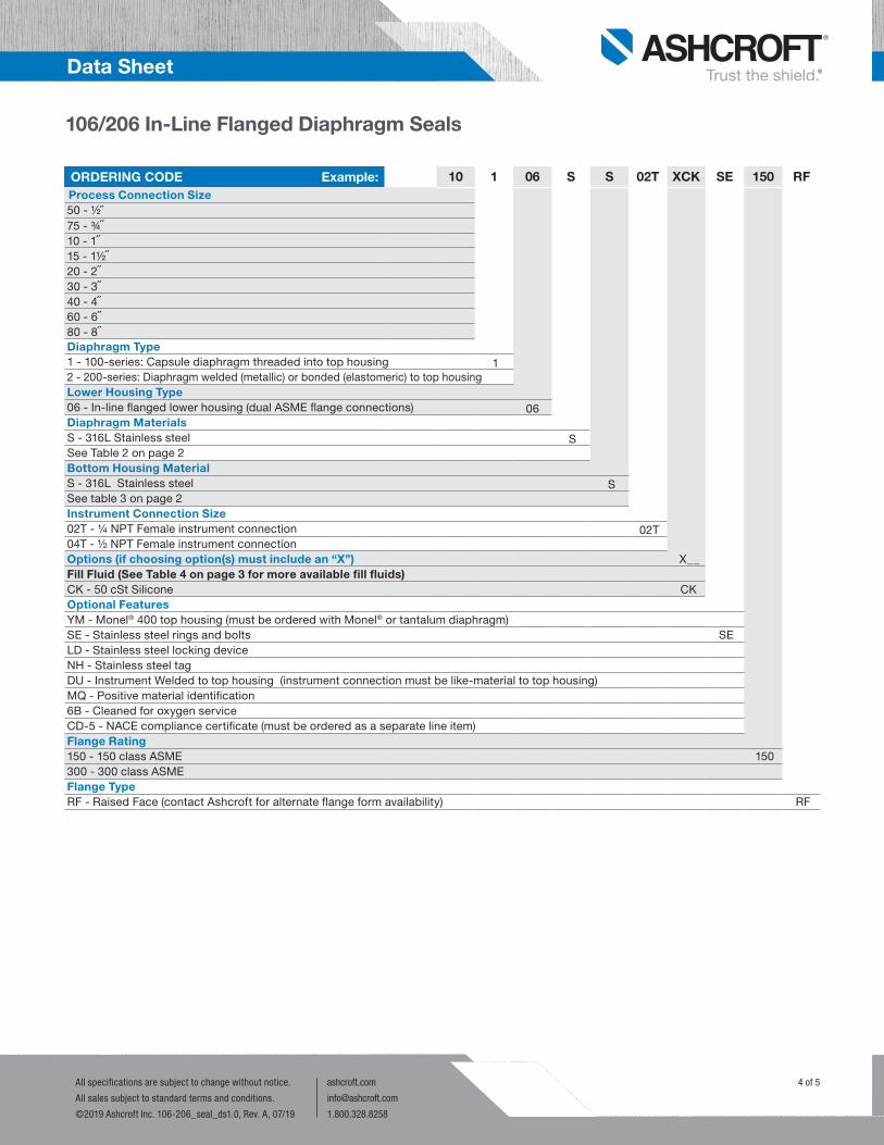
DIMENSIONS in [ ] are millimetersFor reference only, consult Ashcroft for specific dimensional drawings
Flange A B C Size Rating # in mm in mm in mm
150 7 (178) 31⁄2 (89) 1⁄2˝
300 7 (178) 27⁄16 (62)
37⁄8 (98)
150 7 (178) 41⁄4 (108)
1˝
300 8 (203) 27⁄16 (62)
47⁄8 (123)
150 8 (203) 5 (127)
11⁄2 ˝
300 9 (229) 211⁄16 (68)
61⁄8 (155)
150 9 (229) 6 (152)
2˝
300 10 (254) 215⁄16 (75)
61⁄2 (165)
150 11 (279) 71⁄2 (229)
3˝
300 12 (305) 35⁄8 (92)
81⁄4 (254)
A
C
B
Flange A B C Size Rating # in mm in mm in mm 150 13 (330) 9 (229)
4˝
300 14 (356) 33⁄8 (86)
10 (254)
150 16 (406) 11 (279)
6˝
300 17 (432) 47⁄16 (113)
121⁄2 (318)
8˝ 150 16 (406) 57⁄16 (138) 131⁄2 (343)
A
C
B
Size Flange Rating A B C
1/2˝150# 7 [178] 2.44 [62] 3.50 [89]
300# 7 [178] 2.44 [62] 3.88 [98]
1˝150# 7 [178] 2.44 [62] 4.25 [108]
300# 8 [203] 2.44 [62] 4.88 [124]
11/2˝150# 8 [203] 2.69 [68] 5.00 [127]
300# 9 [229] 2.69 [68] 6.13 [156]
2˝150# 9 [229] 2.94 [75] 6.00 [152]
300# 10 [254] 2.94 [75] 6.50 [165]
3˝150# 11 [279] 3.63 [92] 7.50 [191]
300# 12 [305] 3.63 [92] 8.25 [210]
Size Flange Rating A B C
4˝150# 13 [330] 3.38 [86] 9.00 [229]
300# 14 [356] 3.38 [86] 10.00 [254]
6˝150# 16 [406] 4.44 [113] 11.00 [279]
300# 17 [432] 4.44 [113] 12.50 [318]
8˝ 150# 16 [406] 5.44 [138] 13.50 [343]
All specifications are subject to change without notice.
All sales subject to standard terms and conditions.
©2019 Ashcroft Inc. 106-206_seal_ds1.0, Rev. A, 07/19
ashcroft.com
1.800.328.8258
5 of 5
106/206 In-Line Flanged Diaphragm Seals
Data Sheet
106/206 - IN-LINE FLANGED DIAPHRAGM SEAL 1/2˝, 1˝, 11/2˝, 2˝, 3˝
106/206 - IN-LINE FLANGED DIAPHRAGM SEAL 4˝, 6˝, 8˝


![[PSS 2A-1Z11 A] Pressure Seals for Use with I/A Series ...€¦ · RECESSED DIAPHRAGM SEALS Recessed diaphragm seal assemblies are available in flanged, threaded, and in-line weld](https://img.dokumen.tips/doc/110x75/5f759f42347cf3713b4a073e/pss-2a-1z11-a-pressure-seals-for-use-with-ia-series-recessed-diaphragm-seals.jpg)