Embed Size (px)
Citation preview

Data Processing Techniques
This document describes some aspects of microprogram- ming as it has been and is being used in certain IBM processing units. It is intended to provide a general understanding of the subject.
To achieve this objective, the document has been divided into two parts-Part I provides the reader with elementary concepts: what microprogramming is, what it does, how it is used, etc. This material is sufficient for the reader who wishes only a broad understanding of microprogramming. Part I requires no prerequisite knowledge by the reader other than basic data processing concepts.
Part I1 is far more detailed and is intended to provide an understanding of some microprogramming specifics. While the System/370 Models 135 and 145 are used as instructional devices, the material is not intended to be a description of how, or through what vehicles, these devices are microprogrammed. Part I1 requires close attention to detail, and is for those who wish a more explicit description than that provided by Part I. Part I1 presumes some knowledge of assembler language program- ming concepts as well as a basic familiarity with the principles of complement arithmetic.
The document concludes with some recommendations for further reading. IBM does not provide educational or instructional manuals for any specific microprogrammable device. However, the field-engineering maintenance documents peculiar t o the device in question, as an adjunct to their primary objective, may contain further details on certain micro programmable aspects of that device.

CONTENTS [
Overview . . . . . . . . . . . . . . Simulation of Functions . . . . . . . Microcode: The IBM System/360 . . . . Read Only Storage . . . . . . . . . writable Control Storage . . . . . . . System/370 . . . . . . . . . . . Special Features . . . . . . . . . . Considerations of Reloadable Control Storarre Possible Uses of Reloadable Control Storage .
. . . . . . . . . . . . Conclusion
Bart I1
Reloadable Control Storage on the IRM System/370 Models 135 and 145 . . . . . . . . . . . . . . . . . . Background
HorizontalandVerticalMicroprogramming . . . . . . . . Emulation . . . . . . . . . . . . . . . . . . . I/E Cycles . . . . . . . . . . . . . . . . . . . Internal Structure and Data Flow of the System/370 Model 145 . Example of Emulating a System/370 Instruction on the Model 145 Internal Structure and Data Flow of the System/370 Model 135 . Extended Capability . . . . . . . . . . . . . . . . Summary . . . . . . . . . . . . . . . . . . .
. . . . . . . . . . . . . . . . . . . . Bibliography
First Edition (December 1971)
Copies of this and other IBM publications can be obtained through IBM branch offices .
A form hi3 been provided at the back of this publication for readers' comments . If this form has been removed. address comments to: IBM Corporation. Technical Publications Department. 1133 Westchester Avenue. White Plains. New York 10604 .
@copyright International Business Machines Corporation 197 1
PART I
OVERVIEW
Simulation of Functions
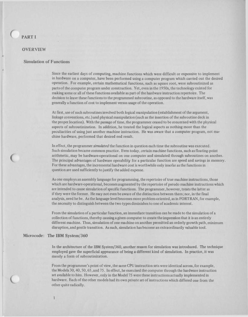
Since the earliest days of computing, machine functions which were difficult or expensive to implement in hardware on a computer, have been performed using a computer program which carried out the desired operation. For example, certain mathematical functions, such as square root, were subroutinized as parts of the computer program under construction. Yet, even in the 1950s, the technology existed for making some or all of these functions available as part of the hardware instruction repertoire. The decision to leave these functions to the programmed subroutine, as opposed to the hardware itself, was generally a function of cost to implement versus usage of the operation.
At first, use of such subroutines involved both logical manipulation (establishment of the argument, linkage conventions, etc.) and physical manipulation (such as the insertion of the subroutine deck in the proper location). With the passage of time, the programmer ceased to be concerned with the physical aspects of subroutinization. In addition, he treated the logical aspects as nothing more than the peculiarities of using just another machine instruction. He was aware that a computer program, not ma- chine hardware, performed that desired end result.
In effect, the programmer simulated the function in question each time the subroutine was executed. Such simulation became common practice. Even today, certain machine functions, such as floating-point arithmetic, may be hardware-operational on one computer and simulated through subroutines on another. The principal advantages of hardware operability for a particular function are speed and savings in memory. For these advantages, the incremental hardware cost is worthwhile only insofar as the functions in question are used sufficiently to justify the added expense.
As one employs an assembly language for programming, the repertoire of true machine instructions, those which are hardware-operational, becomes augmented by the repertoire of pseudo machine instructions which are intended to cause simulation of specific functions. The programmer, however, treats the latter as if they were the former. He may not even be aware of the distinction between them; nor, in the final analysis, need he be. As the language level becomes more problem-oriented, as in FORTRAN, for example, the necessity to distinguish between the two types diminishes to one of academic interest.
From the simulation of a particular function, an immediate transition can be made to the simulation of a collection of functions, thereby causing a given computer to create theimpression that it is an entirely different machine. Thus, simulation of one machine on another permitted an orderly growth path, minimum disruption, and gentle transition. As such, simulation has become an extraordinarily valuable tool.
Microcode: The IBM System/360
In the architecture of the IBM System/360, another reason for simulation was introduced. The technique employed gave the superficial appearance of being a different kind of simulation. In practice, it was merely a form of subroutinization.
From the programmer's point of view, the same CPU instruction sets were identical across, for example, the Models 30,40,50,65, and 75. In effect, he exercised the computer through the hardware instruction set available to him. However, only in the Model 75 were these instructions actually implemented in hardware. Each of the other models had its own private set of instructions which differed one from the other quite radically.

These instruction sets, unavailable directly to a programmer, were more primitive than the visible instruction sets. They carried out only very elemental operations, such as adding one byte to an- other, or moving a byte from one internal register to another. The repertoire of these more elemental instructions constituted a microcode instruction set for a particular machine, with each ins- struction termed a microinstruction. Thus, the Model 30 had a microcode instruction set which differed from the Model 40 microcode instruction set. These sets, in turn, differed from those on the Models 50 and 65, respectively.
Each microcode instruction set was employed to simulate the very System/360 instruction set truly present on the Model 75. To simulate one true System/360 instruction might take many microcode in- structions, the set of which constituted the microprograms for the simulated instructions. It is equally true to conclude that the microprogram for the add instruction, for example, was a different program on each of the Models 30,40, 50, and 65. Nonetheless, the word "simulation" is quite accurate to describe the duties of each microprogram, for simulation was exactly what the duties in- volved. As in the early days of computing, the program used one instruction which resulted in the desired operation being performed by a more primitive set of programmed instructions. Such computers were said to be microprograrnrnable.
Each microprogrammable computer had a programmer's repertoire of instructions, every one of which had its well defined function simulated by a microprogram. The programmer had access neither to the microprograms themselves nor to any microinstruction. Instead, he used a set which could logically be called macroinstructions.
Read Only Storage
Microprograms were stored in a memory and fetched for execution in a fashion completely analogous to a System/360 program, with only one significant exception: the microprogram memory could not be altered by the computer itself. This read only storage could be altered only mechanically. For the Model 30, for example, such alteration involved the preparation of a mylar, 80-column IBM card which contained the microprogram steps plus the insertion of this card into a particular location in the computer.
If, then, the microinstructions of the Model 30, for example, could be used to simulate one computer, the Model 75, why not another? Thus, the IBM 1401 was also simulated using the same primitive set of microinstructions that simulated the System/360 Model 75. Naturally, the microprograms differed in the two cases. (Such simulation, when augmented by special hardware, generally supporting input- output equipment, is frequently termed emulation.)
If a microprogram was logically deficient, it was necessary to correct it with an engineering change which might replace certain read only storage elements.
Writable Control Storage
The Model 25 was introduced as a later addition to the family of System/360.computers. To achieve the desired compatibility, a set of microprograms simulated the programmer's repertoire of System/360 instructions, but, in this case, a different technology was employed to store the microprograms. The identical concept of having a System/360 instruction simulated through more primitive microinstructions was employed, but in the Model 25 the microcode lay in a readlwrite storage. This storage, differing in no way from ordinary processor storage, except for its accessibility and its impact on the behavior of the Model 25, is called writable control storage. There is little difference in function between writable control storage and read only storage. What is essential is that the latter is meAanically altered, whereas the former is electronically altered. Other microprogrammed simulators caused the Model 25 to behave as a 1401 or as a Model 20.

The writable control storage of the Model 25 was also used to simulate some of the functions of hard- ware disk drive adapters, channels, and a communication attachment. Because of the modest size of the writable control storage (1 6K bytes of core or 8K microinstructions), all combinations of attachable features could not be supported. Also, certain combinations of devices were logically inconsistent. Consequently, different core loads of microprograms were employed for different machine combinations. Changing the contents of writable control storage was accomplished by reading the new microprograms, in card image form, through standard 110 devices
The IBM System/370 Models 135 and 145 are microprogrammed computers which utilize the writ able control storage principle. Here it is termed reloadable control storage. In many respects the Models 135 and 145 appear quite similar to the System/360 Model 25. However, it is more important to consider the consequences of their differences than any superficial similarity.
The microcode instruction set for the System/360 Model 25 is different from that of the System/370 Model 135, which, in turn, differs from that of the System/370 Model 145. In all three cases, a different hardware complement (registers, arithmetic and logical units, etc.) is utilized. In consequence, this mandates a different microcode instruction set for each machine, because the microinstructions must drive the data paths of the specific machine for which they have been designed.
Not only is the instruction set different from the model to model, but the microword length is con- siderably diffent between the System/360 Model 25 and System/370 Model 135 (two bytes each) and the System/370 Model 145 (four bytes).
Whatever the individual differences between these microcode instruction sets (repertoire, bit arrange- ment, length, interpretation, cycle time, etc.), the end result is that a microprogram written for one of these models will not run on any other model. That is, the models are categorically imcompatible at the microprogram level. Yet they are quite compatible at the level of the published System/360, System/370 instruction interface.
One new important capability that exists in these System/370 computers is the expandability of reload- able control storage. In the Model 135, the basic 24K bytes of reloadable control storage may be appended with up to two modules of 12K bytes each. In the Model 145, this expandability is achieved by using part of processor storage. Here, the minimum reloadable control storage consists of 32K bytes and increases, in 2K-byte increments, to a 64K-byte maximum. This facility permits simultaneous access to a combination of IBM features which would overflow a fixed minimum amount of reloadable control storage. These microprograms reside on a read only, special purpose file, and are loaded to reloadable control storage at initial microprogram load time, or by the IBM customer engineer for diagnostic purposes.
Thus, there is the important flexibility of simultaneity in feature availability at the expense of additional control storage in the case of the Model 135, or a portion of processor storage in the case of the Model 145. The user, therefore, achieves and retains considerable advantage by such an economical imple- mentation of features. Note also that some writable control storage exists in the System/370 Model 165. While it is used to a much lesser extent than that of the Model 145, it is an important aspect of the advanced design of the Model 165. There is no writable control storage on the System/370 Model 155, but this system uses read only storage to accomplish the same functions.

Special Features
Because of the utility of reloadable control storage, it is natural for both IBM and the user to be interested in it as a vehicle which can be fashioned to particular applications through the development of special features and RPQ's.
Special features on a computer are not new. By means of reloadable control storage, it may be possible to implement special features more readily than in the past.
Considerations of Reloadable Control Storage
The consequences of alternate uses of reloadable control storage must be assessed as carefully as possible. Although reloadable control storage can be altered to provide a variety of functions, other avenues for providing the same functions may be far more appropriate and efficient. For example, if performance is a problem, a careful examination of the computer program in question may lead to the use of better programming or numerical techniques. Such a direction may have far greater influence on performance than a microprogrammed feature.
The foremost consideration of alternate uses of reloadable control storage is the loss of compatibility which can be occasioned by the indiscriininate use of microprogramming:
It may not be possible to implement the same feature even on a kindred machine within a com- patible family of computers.
A particular application may cease to function if the computer in use is either increased or decreased in size or power.
The relative performance improvement expected, when going to a more powerful member of the computer family, may not be achieved for a specific application. ( The next-larger computer in the family may not use reloadable control storage. If it uses read only storage, there may be physical limitations on size which prevent the implementation of the feature. Alternatively, the cost of hardware to carry out the equivalent function may be prohibitive.
It is possible to introduce microprogrammed features which make it impossible to use the standard operating systems of the installation. The consequent cost of a special operating system, or no system at all, may easily outweigh any throughput advantage gained by the microprogrammed feature.
Another important consideration is the general direction of programming as a vehicle for man-machine communication. This direction is toward cost reduction and ease of use through the employment of higher-level languages. Microprogramming runs counter to this trend and tends to increase, rather than decrease, the cost of programming.
The present state of the art in microprogramming techniques can also make the debugging of the code considerably more time-consuming and difficult than in conventional programming. Inadvertent microprogramming errors can cause serious operational problems, such as making inoperable a channel or modifying the System/370 instruction set, with all the attendant consequences for the operating system or other application programs.
Still another consideration concerns IBM's use of reloadable control storage to implement certain engineering changes. Such changes have the potential of invalidating microprograms written by the user to satisfy his particular requirements.

Finally, it should be quite clear that the interface to the user is supported at the System/370 instruction level. Compatibility at this level has been rigorously maintained so that a program in System/370 machine languaqe can be run on any System1370 machine. This not only allows for a backup and great convenience in multicomputer installations, but also provides a growth path for the future.
Such is not the case with microprograms! A microprogram written for one model is operable only on that one model. Thus, a microprogram's useful life is limited to the life of the model for which it was originally written. It cannot be expected to run on any future models.
Possible Uses of Reloadable Control Storage
Two of the primary purposes for using microprogramming techniques - performance improvements and added functional capability - have been previously mentioned. while it is not possible to list all. uses, some general remarks may be of value.
Performance improvements in particular problems have been obtained through the use of special instructions. This is to be expected for two reasons:
1. No instruction set can be expected to be optimal for all problems.
2. A machine dedicated to a particular problem will invariably perform better than one which is carrying an overhead of an operating system to make it a more general purpose and flexible computer.
The experience to date indicates that the greatest performance improvements to be expected by the use of microprogramming techniques are in the areas of logical operations rather than arithmetic operations. However, the attendant consequence of changes to instruction sets may be the incom- patibilities and other operational difficulties previously discussed.
There is also the issue of extending the capability of computers by providing simulators for other computers, such as the l4Ol simulator (emulator) for the System1370 Model 145. Experience indicates that while it may be fairly simple to simulate the CPU function of a computer, the simulation of 110 .
may be prohibitive. In any case, it may be difficult to achieve desired performance objectives without some additional hardware. The simulation of I10 functions also has the highest probability of being affected by engineering changes in the writable control storage.
In addition to the simulation of other machines, typical capabilities which have been considered include special multiplexers and special graphic processors. Applications exist for real-time data acquisition problems and problems in pattern recognition. The use of reloadable control storage in computer science courses involving machine design could prove to be a valuable tool.
Finally, the most important thing to remember is that if microprogramming is used to implement a new function, any program which uses that function will run only on a machine which has that function provided. The microprogram cannot be used to provide that function on other models.
Conclusion
The material in Part I1 is intended to provide a more detailed knowledge of microprogramming through an elementary description of certain microprogrammable aspects of System/370 Models 135 and 145. The information requires considerable attention to detail. It will yield an elementary understandin? of emulation and computer architecture in general and of microprogramming in particular.
PART 11
RELOADABLE CONTROL STORAGE ON THE IRM SYSTEM/370 MODELS 135 AND 145
Background
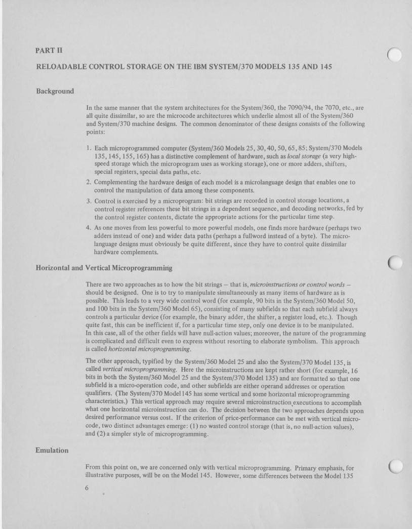
In the same manner that tlie system architectures for the Systeml360, the 7090194, the 7070, etc., are all quite dissimilar, so are the microcode architectures which underlie almost all of the System1360 and System1370 machine designs. The common denominator of these designs consists of the following points:
1. Each microprograrnrned computer (System1360 Models 25,30,40,50,65,85; System1370 Models 135, 145, 155, 165) has a distinctive complement of hardware, such as local storage (a very high- speed storage which the microprogram uses as working storage); one or more adders, shifters, special registers, special data paths, etc.
2. Complementing the hardware design of each model is a microlanguage design that enables one to control the manipulation of data among these components.
3. Control is exercised by a microprogram: bit strings are recorded in control storage locations, a control register references these' bit strings in a dependent sequence, and decoding networks, fed by the control register contents, dictate the appropriate actions for the particular time step.
4. As one moves from less powerful to more powerful models, one finds more hardware (perhaps two adders instead of one) and wider data paths (perhaps a fullword instead of a byte). The micro- language designs must obviously be quite different, since they have to control quite dissimilar hardware complements.
Horizontal and Vertical Microprogramming
There are two approaches as to how the bit strings - that is, microinstructions or control words - should be designed. One is to try to manipulate simultaneously as many items of hardware as is possible. This leads to a very wide control word (for example, 90 bits in the System/360 Model 50, and 100 bits in the System/360 Model 65), consisting of many subfields so that each subfield always controls a particular device (for example, the binary adder, the shifter, a register load, etc.). Though quite fast, this can be inefficient if, for a particular time step, only one device is to be manipulated. In this case, all of the other fields will have null-action values; moreover, the nature of the programming is complicated and difficult even to express without resorting to elaborate symbolism. This approach is called horizontal microprogramming.
The other approach, typified by the System1360 Model 25 and also the System1370 Model 135, is called vertical microprogramming. Here the microinstructions are kept rather short (for example, 16 bits in both the System1360 Model 25 and the System1370 Model 135) and are formatted so that one subfield is a micro-operation code, and other subfields are either operand addresses or operation qualifiers. (The System1370 Mode1 145 has some vertical and some horizontal microprogramming characteristics.) This vertical approach may require several microinstruction~executions to accomplish what one horizontal microinstruction can do. The decision between the two approaches depends upon desired performance versus cost. If the criterion of price-performance can be met with vertical micro- code, two distinct advantages emerge: (1) no wasted control storage (that is, no null-action values), and (2) a simpler style of microprogramming.
From this point on, we are concerned only with vertical microprogramming. Primary emphasis, for illustrative purposes, will be on the Model 145. However, some differences between the Model 135

Control Storage
and the Model 145 will also be discgssed. Figure 1 illustrates a microprogram residing in control storage. The hardware routes microinstructions to the control register, where they can then typically cause the following sorts of actions:
Specify that the contents of one or two local storage locations, and possibly an immediate va lu~ from the microinstruction itself, are to be combined in some logical manner in the Arithmetic Logical Unit (ALU) and are to be routed back to a local storage location. Typical operations include plus, minus, and, or, exclusive or, decimal add, etc.
Specify that data is to be moved from one local storage location to another, possibly with some alteration in the process.
Specify that data is to be transmitted between a local storage location and either a program-addressable storage location or an external device.
Specify that the location from which the next microinstruction should be loaded into the control register depends upon some combination of data values is the ALU or in a local storage location.
Decode operatton r y p L I Read Synemr370 lnstruct~on from 6 to LS 1
I I
I
I Fetch operands from PS to LS I ~-7- Execute System1370 --
\.
Control S~gnals to Control Storage ALU. Program Storage, Local Storage, etc
Control Reglstw
Local Storage
Boundary 1 1 'nstruct'On "la 1 1 1 Ayj I I I I I I - - - - - -
I I I I I I Object Programs (Systemi3701
Program Storage
Figure 1. General microprogram flow
Whereas the control storage contains microprograms, the program storage contains instructions (System/370) and data. The microprograms emulate the System/370 archrtecture on the Model 145 by repeatedly executing the code which resides in the control storage area of Figure 1 ; that is, emulation is accomplished by microprograms performing, or assisting in the performance of the following five functions:
1. Fetching the line of System/370 object code from program storage to local storage to begin the decoding process
2. Decoding the operation type by examining and branching upon the OP code field
3. Fetching operands from program storage to local storage, as required by the System/370 instruction being decoded
4. Transferring control to a block of microcode that performs the particular Systeml370 operation
5. Returning control to (1) unless there is an interrupt condition to be serviced by an appropriate microroutine

I/E Cycles
Almost all digital computers, microprogrammed or otherwise, proceed via alternation of instruction and execution cycles (1/E cycles). I-cycles are times during which (1) instructions (that is, System/370 executable code) are fetched and decoded, and (2) operands are fetched. The instruction fetch and decode portion of I-cycles takes the same amount of time in all cases. The operand fetch portion of I-cycles varies with the number and nature of operand references within the instruction being decoded.
E-cycles are times during which the sequences particular to different instructions are performed; thus, there are as many blocks of E-logic as there are different instructions in the machine's repertoire. In simple instructions, the E-cycles can be even more brief than I-cycles. However, in more complex instructions, such as division, the time in E-cycles predominates.
In the discussion of emulation in the previous section, steps 1 to 3 together constitute I-cycles; steps 4 and 5 constitute E-cycles.
In the System/370 Models 135 and 145, explicit recognition is given to the importance of the time spent in I-cycles by the incorporation of I-cycles hardware, and the sharing of I-cycles logic between hardware and microcode. Specifically in the case of the Model 145 :
@ Three fullword hardware registers are used for buffering System/370 instructions.
Hardware controls cause the contents of the buffer to be prefetched by triggering certain prefetch cycles (except for branch instructions).
Decoding is assisted via a hardware-forced branch on the System/370 operation code to one of several E-cycles entry points in the microcode.
Special, high-speed, supplemental local storage registers are assigned to assist for the duration of the I-cycles sequence.
Internal Structure and Data Flow of the System/370 Model 145
The internal structure and data flow of the System/370 Model 145 are shown in Figure 2. The Model 145 has a minimum of 163-K bytes of monolithic processor storage.This includes both program storage and control storage, and incorporates Error Checking and Correction (ECC) codes instead of single- parity bits. Monolithic storage is volatile - that is, it loses its contents on a power-off condition. Be- cause program storage and control storage are physically identical, a power-off condition causes the contents of both areas t o be lost. Thus, the first step after power-on must always be a bootstrap process to reload control storage (IMPL or Initial Microprogram Load).
A microcode-accessible register is used to set a boundary in processor storage; everything below it (that is, lower addresses) is program storage; everything equal to and above it (that is, higher addresses) is con- trol storage. The boundary information is written into a fixed control storage location at IMPL time, and it is copied from there into a boundary register with every execution of the system-reset microprogram. The boundary is set so as t o give at least 32K bytes of control storage, (standard), but it may be respeci- fied toward lower processor storage in increments of 2K bytes. As an example, consider a Model 145 with 288K bytes of processor storage. During IMPL time, the boundary will be established so that the features ordered will fit into control storage. This can divide the 288K bytes of our example machine into 32K control storage bytes and 256K program storage bytes. However, a system with expanded 110 facilities might have 34K bytes of control storage and 254K bytes of program storage. The control storage maximum is 64K bytes.

Control Storage
- - - - - External Address
To decode network
Boundary Register
Z Register u I I T o A , B Registers *
I D Register I
Figure 2. Simplified System/370 Model 145 CPU data flow
As with any conventional storage, there are storage address registers t o select the location to be accessed. In the case of the Model 145, the accesses t o storage contents will be principally to micro- instructions from control storage and less frequently t o data (that is, System/370 instructions or operands) from program storage. Still less frequently, there will be storage references caused by traps (for example, t o fixed microroutines for exceptional conditions) or forces (for example, hardware- generated microinstructions which concern themselves with transmission of data to and from external devices).
Thus, the storage address registers have several inputs:
1. From the boundary register, t o specify where control storage begins
2. From local storage, t o specify the accessing of data from program storage
3. From the control register, to specify the next microinstruction
4. From forces, traps, etc.
Microinstructions are routed successively to the control register at a rate dependent upon their types (the Model 145 has a variable cycle time). For the control register t o be able t o accept the next microinstruction at the proper time, the working storage for the microprogram - that is, the local storage - must operate quite fast. In fact, it has a 24-nanosecond read time and a 50-nanosecond cycle time between successive read-outs.
9

The local storage consists of two monolithic devices, A local storage and B local storage, each holding 64 fullwords (with parity bits). The contents of these devices are normally identical. A microinstruction directing data to be placed in a local storage location causes it to be placed in that location in both devices. The two exceptions to this identity would be an error condition or a diagnostic situation. The primary reason for having two devices is t o allow simultaneous access to the contents of two distinct locatjons. This yields an ancillary benefit associated with error!retry situations.
Local. storage on the Model 145 is used for a variety of purposes: for scratch pad storage; for retaining the general purpose registers and the floating-point registers; and for miscellaneous items, such as the program instruction counter, channel information, condition code, operand addresses, etc.
The output of main storage goes, via the SDBO (Storage Data Bus Out), to one of three principal destinations:
1. The control register (the data is a microinstruction)
2. The local storages
3. An external location
Microinstructions (thus, also the control register) are four bytes wide:
Jn general:
1. Byte CO js the micro-operation or control word type.
2. Byte C1 is an address for data in A local storage.
3. Byte C2 either is an address for data in B local storage or may be an immediate address. In the latter case, the address itself is used as data.
4. Byte C3 contains information about the location of the next microinstruction to be fetched.
'These general rules have numerous exceptions wherein unused bits in the bytes modify the interpre- tratjotl of CO and C3.
TygjcalXy, C! will have a local storage address that causes the data from that location in A local storage to be rou.ted th~cugh the A register to the ALU, and C2 will have a local storage address that causes the data from that location in B local storage to be routed through the B register to the ALU. The A and B registers are fullword registers used for staging inputs to the adders. But they also, in conjunction with the A byte and B byte assemblers, perform certain pre-adder functions, such as complementing inputs for subtraction, masking subfields; transposing subfields, etc.
There are two one-byte adders, ALU2 and ALU3. If byte arithmetic is signaled by the microinstruction, the operation i s performed in duplicate, in ALU2 and ALU3, and the outputs are checked for agreement. If word arithmetic is signaled, ALU2 and ALU3 operate as a halfword adder, and two passes through ALTJhnd ALUI? accomplish the function.

The output from the ALU's is staged in both a Z register - for direct routing back to the A and I3 registers, if necessary - and a D register - for transmittal to either local storage or an external facility. The path from the Z register to the A and B registers allows the result of any microinstruction to be immediately available as data for the next microinstruction. However, if data, obtained as a result of one microinstruction execution, is to be used by the next microinstruction, its destination must be in local storage. The only other destination for data, external registers, does not permit valid access of that data by the next microinstruction.
Example of Emulating a System/370 Instruction on the Model 145
We have already alluded to the general ty.pes of microinstruction functions that are available - arithmetic, move data, transmit data, anflbranching. Representative forms employed in the Model 145 are shown in Figure 3, and their broad functional uses are summarized in Table 1. However, it is more instructive to discuss a small portion of microcode, excised from the System/370 emulator, as it has been microprogrammed on the Model 145 (see Figure 4). The sample shown is that microcode which is executed chronologically in the interpretation of the instruction CR 7, 8 (compare contents of general purpose registers 7 and 8).
Some preliminary comments are in order:
1. The coding is expressed symbolically and is translated by a microcode assembler. This assembler is an IBM proprietary program which is not supported for external dissemination.
2. Microcode is arranged in routines, each of which has a symbolic name. Microinstructions may have symbolic labels which, as in ordinary assembly language programming, are completely arbitrary.. Thus, a particular control word is identified by specifying the routine identifier and the label identifier.
3. Operand symbolics of microinstructions, unlike ordinary assembly language programming, are not arbitrary. The symbols employed for operands have fixed significance. These symbols are trans- lated by the microcode assembler to appropriate local storage or external device references. Some examples of such nonarbitrary operands are U, I, S, LL, and Y 1.
4. Microinstructions are on fullword boundaries. A group of 64 microinstructions is termed a module. There are a maximum of 256 modules of control storage in a Model 145, with the boundary ad- justed for 64K bytes of control storage. To branch from microcode in one module to microcode in another module requires an explicit microcode instruction.
5. Each microinstruction is, in general, capable of performing four actions. These actions correspond to entries in four symbolic input fields with the following headings:
Next Label BX BH BL Stat Statement
a. Next Label - indicating the label of the next microinstruction to be executed.
b. BX BH BL - qualifying the next instruction label according to values given immediately in these fields or according to data values specified by these fields. As an example, consider a micro- instruction where the Next Label field contains "NEXT" and the BX BH BL field contains " 1, S4, S5". Thus, the instruction appears (in part) as:
NEXT 1, S4, S5
This implies that NEXT is actually a block of eight microinstructions with labels NEXT000, NEXT001, NEXT010, . . . , NEXT1 11. S4 and S5 specify bits 4 and 5 of a special S register. If S4 and S5 have values 0 and 1 at this instant in this example, then the next instruction reference will be to symbolic label NEXT I 0 1.


I
I SEQUENCE I
1 GARR 1 0 7
GARR 1 0 8
GCAG 2
I I GCAG 3
GCAG 4
GCAG 5
GCAG 1 8
GCAG 1 9
GCAG 20
GCAG 2 1
GCAG 2 2
CHOF L
CHOF L
CHOF L
CHOF L
SETCC
SETCC
SETCC
SETCC
ElJlJ
c. Stat - specifying that certain status bits are t o be posted in the special eight-bit S register, indicating conditions produced by the most recently executed microinstruction. These condi- tions include such items as zero/nonzero, carry, invalid decimal digits, etc. Stat entries can also modify execution of the current microinstruction.
d. Statement - performing an arithmetic/logical function upon the contents of two storage loca- tions, or causing the transmission of data from one location to another.
6. The other two principal input fields to the microcode assembler are the Label field and the Com- ments field. The Label field may have a qualifying postfix, termed a -- Leg, as in the example shown above:
7. Output from the microcode assembler has a Sequence column, as in Figure 4.
LEG
GCAG CHOF L
SETCC
SETCC
CHOF L
CHOF L
END
E IJU
END
END
BX E H B L S T A T
S 1 2
S1, S 3
S2, BO
S2, BO
1, 1
1, 1
0, x
STATEMENT
YC = L H - Y + 1
YO
YO
YO = YO,OE,K80
YO a YO,OE,K80
UO = UOL,OE,KOO
UO = UOL,OE,KOO
UO = UOL,OE,K20
UO = UOL,OE,K10
RTN L I N K
COMMENTS
SUBTRACT R 2 FROM R1.
T E S T FOR OVERFLOW.
B9ANCH TO S E T COND. CODE.
BRANCH TO S E T COND. CODE.
OVERFLOW. I N V E R T S l G N B I T .
OVERFLOW. I N V E R T S l G N B I T .
S E T COND. CODE OF 0.
S E T COND. CODE OF 0.
SET COND. CODE OF 2.
SET COND. CODE OF 1.
END OF OP.
Figure 4. Model 145 microcode exerpt of CR 7 , 8

Let us now extract some signicicance from Figure 4. The System/370 instruction we are emulating is "CR 7 ,8" (or 1978 in hexadecimal). The groupings 1-3,4, and 5 below correspond to the functional objectives as tabulated previously in the section entitled "Emulation".
1-3 The I-cycles hardware (microcode-assisted) performs a variety of activities the details of which need not concern us here. At the conclusion of I-cycles, the following conditions exist:
The registers U2 and U3 (the low-order two bytes of local storage register U) contain the original System/370 instruction "CR 7,8", with the hi2h-order eight bits in U2 and the low-order eight bits in U3.
The contents of special byte register S are identical with the contents of register U2 (that is, the op code "19").
The contents of special byte register L are identical with the contents of register U3 (that is, the names of the registers whose contents are being compared: "78").
The fullword, local storage register Y contains the contents of general purpose register 8 .
4 Routine GARR has code for all RR functions. Line GARR 107 does the fullword differencing, leaving the result in local storage register Y. Special byte-register L is used (the high-order hexa- decimal part) t o access general purpose register 7 indirectly. From this, the contents of register Y are directly subtracted. A "1" is added to change from ones complement to twos complement arithmetic. The operand YC determines the destination of the subtraction as being register Y, with the C indicating the saving of the carry. When this operation is performed, an entry in the Stat field directs that S register bits 1 and 2 shall be set to reflect the nature of the result. The next microinstruction is to be taken unconditionally, and is GARR 108.
Here no operation is performed other than to branch conditionally upon the values of bits S1 and S3. The next four lines of code test to distinguish the cases of overflow versus no overflow. If sequence GCAG 2 or 3 is employed, a direct branch occurs to SETCC, modified by bits S2 and BO, where BO refers t o the branch source YO. If sequence GCAG 4 or 5 is employed, the high-order sign bit will be inverted by performing an exclusive or (OE) with the hexadecimal con- stant 80. A direct branch to sequence GCAG 3 will then occur.
In this way, control proceeds from this set of four lines t o one line of the next set of four (GCAG 18-21), where the condition code is set. The condition code is maintained within byte UO of the register U in local storage. These last four instructions do not have a BL subfield. However, since the microcode assembler will not permit this field to be blank if the BH subfield has been em- ployed, the arbitrary symbol X is selected for insertion here.
5 Finally, a return is made to I-cycles to fetch the next System/370 instruction. The microcode that established the return link is not shown in the sample. The return is conditional upon there being no interrupt conditions that need servicing and would direct control to other microroutines.
Internal Structure and Data Flow of the System/370 Model 135
In principle, microprogramming the Model 135 does not differ from the general description for the Model 145. However, as a comparison of Figure 2 and Figure 5 will show, the internal structure and data flow of the two models differ considerably from each other. For example, in the Model 135 there is only one ALU versus two in the Model 145; one auxiliary storage and one local storage in the Model 135 versus two identical local storages in the Model 145; etc. Thus, since different hardware compo- I nents are to be controlled in the different machines, different operations (that is, different micro-

instructions forming different microprograms) will have to be executed to achieve the same effect. This further highlights the fact that a microprogram written for the Model 145 will not run on the Model 135. The converse is also true. This total absence of compatibility is an important considera- tion in any evaluation of the worth of microprogramming a particular routine or problem.
Control Register
Processor storage of the Model 135 may range in size from 96K bytes to 240 bytes, while the control storage is 24K, 36K, or 48K bytes in size, depending upon user options. In contrast to the Model 145, this is not done at the expense of processor storage; thus, there is no boundary register. As in the Model 145, monolithic storage technology is used. It also incorporates ECC codes and is volatile.
r
The local storage is a 128-byte monolithic device consisting of eight zones of eight halfwords each. This is similar to the local storage of the Model 145. Zones are assigned for use by the CPU, multiplexer channel, selector channels, etc. Only one zone may be actively involved in a particular task at a given point in time. When the CPU zone is active, another monolithic device, the auxiliary storage, may be used. This is also 128 bytes in size and contains the general purpose registers, the floating-point regis- ters, and 16 halfwords of work area.
Externals
110, etc.
Bus In 1 Byte
w
The ALU is two bytes wide and performs the following operations: Add, subtract, or, and, and not, pass, and complement. Operands to input P may be left-shifted two bits or right-shifted four bits by passing the data through the T register. All data from the local storage is transferred to the auxiliary storage through the ALU.
Control and Program Storage
J 1 J
f A - P - J -
-
Local Storage
Storage Address Registers
\07 Aux~l~ary Storage
To Decode Network 4 A
W
T Reg~ster
A A A A '7 , * Q 1-0 --
I P Complement
Forces, Traps Lk Control Reglster
ALU
Local Storage S
Figure 5. Simplified System/370 Model 135 CPU data flow I

Data is transferred between the CPU and the channels or 110 adapters through an internal 110 interface. ( Data from the adapters to the CPU is transferred via BUS IN (a one-byte data bus), while data from the CPU to the adapters is transferred via BUS OUT.
The length of each microinstruction is 16 bits. To achieve the wide range of operations outlined in Table 2, the control fields within the microinstructions overlap. Also, it is necessary to use specified areas of different control fields as part of the operation decoder, and these areas vary from instruction to instruction. Thus, there is no simple operation decode field. Unlike the Model 145 microinstruc- tions, the Model 1 35 microinstructions do not provide for operations in parallel. As such, they re- semble those used in the System/360 Model 25.
In particular, the Model 135 requires an explicit branch instruction to chanqe the sequence of opera- tions, while the Model 145 can branch with each instruction type. As in the Model 145, the branch address must be on a control word boundary, and the control storage is, in effect, divided into modules. However, in the Model 145, a specific microinstruction must be used to branch out of the current module, while in the Model 135, the explicit branch als.:, serves this purpose as long as a limitation of 4K halfwords on a change in address is observed. If a greater change is required, this is most easily per- formed using the special microinstruction Branch and Link.
The execution times of the various microinstructions differ, ranging from a minimum of 275 nano- seconds for most branch instructions and those arithmetic instructions with a byte or halfword operand, to a maximum of 1430 nanoseconds for some I-fetch instructions processing fullword instructions.
Extended Capability
Reloadable control storage in the System/370 Models 1 35 and 2 45 is also used for purposes other than the implementation of the System/370 instruction set. It is used to help implement the Selector Channels, Block Multiplex Feature, and the Integrated File Adapter. Such use helps to reduce the over-
(
all system cost, but also points out that reloadable control storage may be used to extend the functional capability of the system.
Emulators for other machine designs are, of course, one of the more common ways of extending the capability of the machine. The emulation of the 1401 on the System/370 Model 145 is one example.
Summary
The preceding discussions have been presented to acquaint the reader with the elementary technical aspects of microprogramming. The application of these concepts to particular situations should be approached with due regard to such questions as the following:
Will altered microcode have the desired effect on performance?
@ Will a system that is incompatible with the System/370 be a problem now or in the future?
Will the user require a similar new function on his next machine? Can it be provided?
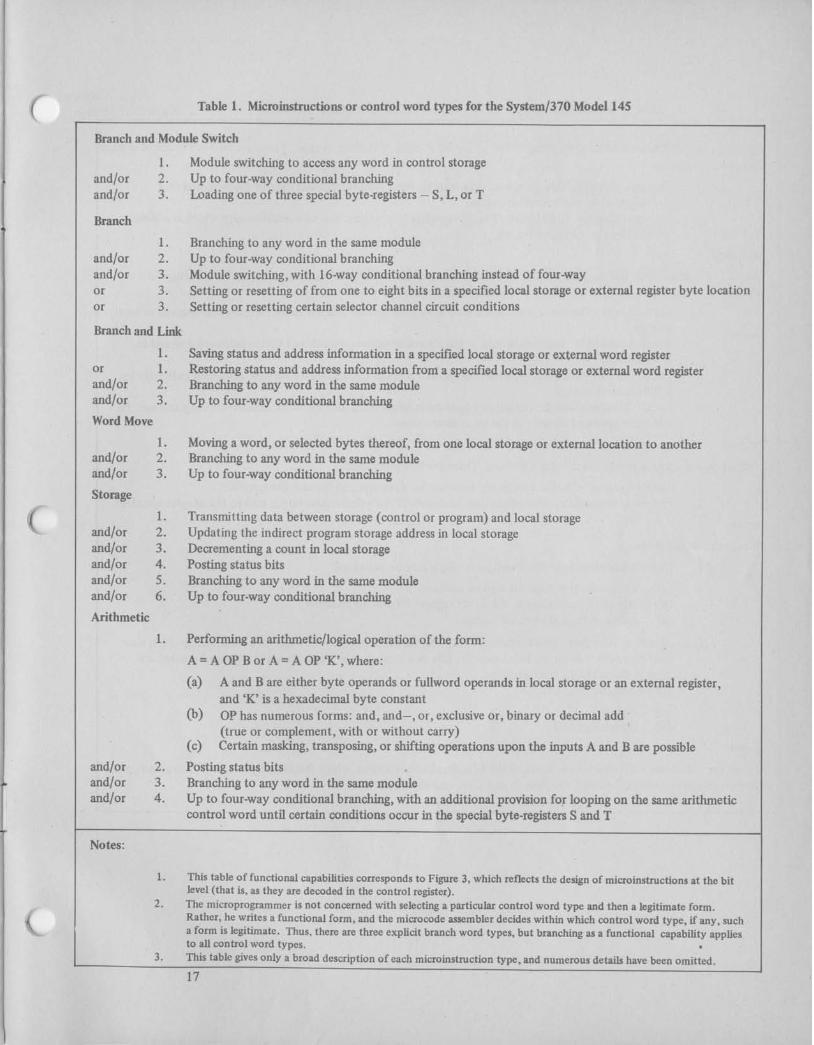
Table 1 . Microinstructions or control word types for the ~ystem/370 Model 145
Branch and Module Switch
1. Module switching to access any word in control storage and/or 2. Up to four-way conditional branching and/or 3. Loading one of three special byte-registers - S, L, or T
Branch
1. Branching to any word in the same module and/or 2. Up to four-way conditional branching and/or 3. Module switching, with 16-way conditional branching instead of four-way or 3. Setting or resetting of from one to eight bits in a specified local storage or external register byte location or 3. Setting or resetting certain selector channel circuit conditions
Branch and Link
1. Saving status and address information in a specified local storage or external word register or 1. Restoring status and address information from a specified local storage or external word register and/or 2. Branching to any word in the same module and/or 3. Up to four-way conditional branching
Word Move
1. Moving a word, or selected bytes thereof, from one local storage or external location to another and/or 2. Branching to any word in the same module and/or 3. Up to four-way conditional branching
Storage
1. Transmitting data between storage (control or program) and local storage and/or 2. Updating the indirect program storage address in local storage and/or 3. Decrementing a count in local storage and/or 4. Posting status bits and/or 5 . Branching to any word in the same module and/or 6. Up to four-way conditional branching
Arithmetic
1. Performing an arithmetic/logical operation of the form:
A = A OP B or A = A OP 'K', where:
(a) A and R are either byte operands or fullword operands in local storage or an external register, and 'K' is a hexadecimal byte constant
(b) OF has numerous forms: and, and-, or, exclusive or, binary or decimal add (true or complement, with or without carry)
(c) Certain masking, transposing, or shifting operations upon the inputs A and B are possible
and/or 2. Posting status bits and/or 3. Branching to any word in the same module and/or 4. Up to four-way conditional branching, with an additional provision for looping on the same arithmetic
control word until certain conditions occur in the special byte-registers S and T
Notes:
1. This table of functional capabilities corresponds to Figure 3, which reflects the design of microinstructions at the bit level (that is, as they are decoded in the control register).
2. The microprogrammer is not concerned with selecting a particular control word type and then a legitimate form. Rather, he writes a functional form, and the microcode assembler decides within which control word type, if any, such a form is legitimate. Thus, there are three explicit branch word types, but branching as a functional capability applies to all control word types.
3. This table gives only a broad description of each microinstruction type, and numerous details have been omitted.
17

Table 2. Microinstructions or control word types for the System/370 Model 135 --
I Storage 1 / Data is transferred between local storage and either processor storage or control storage. There are two subclasses of storag
1 microinstructions: ~ 1. Storage-Indirect. The storage address is taken from local storage and may be incremented or I decremented by the microinstruction.
2. Storage-Directly Addressable. The storage data is in a fured area of control storage which is addressed directly by the microinstruction.
Arithmetic
The ALU processes data, and the result is placed in local storage. The ALU also transfers data from local storage to auxiliary storage. There a1 e four subclasses of arithmetic microinstructions:
1. Local-Local. The two operands are read from local storage and the result replaces one operand in local storage.
2. Local-Immediate. Immediate data in the microinstruction is combined with a halfword operand in local storage.
3. Local-Auxiliary Indirect. The second operand is taken from auxiliary storage, addressed indirectly by a digit in local storage.
4. Local-Auxiliary Direct. The second operand is taken from the CPU work area of auxiliary storage. Its address is specified directly in the microinstruction.
External
External microinstructions use the adapter interface. There are two subclasses:
1 . Local-External. Data is transferred between local storage and the adapter specified. 2. External-Immediate. Immediate data contained in the microinstruction is sent to the adapter specified.
Branch
There are three subclasses:
1. Conditional Branches. The conditions which may be tested are:
(a) A bit in local storage for zero or nonzero (b) One of 16 conditions in the direct register for zero or nonzero (c) A digit in local storage for nonzero
2. Multiway Branches. This includes 16-way branches according to the value of a local storage digit; also, four-way branches on the two low-order bits of a local storage digit. Special multiway branches are used in the multiply microprogram.
3. Unconditional Branches.
(a) Branch (b) BranchandLink
Special
This category includes such microinstructions as the I-fetch microinstruction, which fetches a System/370 instruction, and a Return microinstruction used with the Branch and Link microinstruction.

( BIBLIOGRAPHY
Husson, S. S.
Wilkes, M. V.
Rosin, R. F.
Tucker, S. G.
Microprogramming: Principles and Practices, (New Y ork : Prentice-Hall, 1970)
"Microprogramming," Proceedings DJCC, (Dec. 1958), p. 18
"Contemporary Concepts of Microprogramming and Emulation", Computing Surveys, Vol. 1, No. 4, (1969), p. 197
"Microprogram Control for System/360", IBM Systems Journal, Vol. 6 , No. 4, (1967), p. 222

International Business Machines Corporation Data Processing Division f133 Westchea+er Avenue, White Plains, Mew York 1Q604 (u.s.A. onrv]
IBN world Trade Corporation 1(24 United Vations Plaza, Pew vork, New Vork 10017 /Wernat~~narJ

. An Introduction to Microprogramming G F20-0385-0
Please comment on the usefulness and readability of this publication, suggest additions and deletions, and list spzci6c errors and omissions ( give page numbers). All comments and sugges- tions become the property of m ~ . If you wish a reply, be sure to include your name ~ n d ad2ress.
fold
. fold
fold
fold -
Thank you for your cooperation. No postage necessary if mailed in the U.S.A. FOLD O N D V O LJNES, STAPLE A N D IlrAIL.

Your comments on the other side of this form will help us improve future editions of this pub- lication. Each reply will be carefully reviewed by the persons responsible for writing and pub- lishing this material.
Please note that requests for copies of publications and for assistance in utilizing your IBM
system should be directed to your IBM representative or the IBM branch office serving your locality.
fold
....................................................................
B U S I N E S S R E P L Y M A I L N O POSTAGE NECESSARY IF MAILED IN THE UNITED STATES
. POSTAGE WILL BE PAID B Y . .
IBM Corporation
1 133 Westchester Avenue
White Plains, N.Y. 10604
Attention: Technical Publications
fold
FIRST CLASS
PERMIT N O . 1359.
WHITE PLAINS, N. Y.
fold fold
International Business Machines Corporation Data Processing Division 1133 Westchester Avenue, White Plains, New York 10604 [U.S.A. only]
I B M. World Trade Corporation 821 United Nations Plaza, Mew York, Mew York 10017 [International]