Embed Size (px)
Citation preview

SeaBat 7k Data Format, Volume I Version 2.22
Drawing Number 12713 May 7, 2012
Notice of Proprietary Rights
This document contains confidential and proprietary information. Possession of this document or any part thereof in any form constitutes full acceptance of the terms and conditions of the mutual Non-Disclosure Agreement in effect between the Recipient and RESON Group.
The contents of this document are preliminary and subject to change without notice. This document confers upon the recipient no right or license to make, have made, use, sell, or practice any technology or inventions described herein. The contents of this document, nor any part thereof, may not be copied or distributed in any form without permission in writing from RESON Group.
DATA FORMAT DEFINITION DOCUMENT
SeaBat 7k Data Format, Volume I
Version 2.22
RESON A/S
Fabriksvangen 35
DK-3550 Slangerup
FOR PUBLIC USE

SeaBat 7k Data Format, Volume I Version 2.22
Drawing Number 12713 May 7, 2012
Revision History:
Date Author Rev Description
07/05/2012 MHA 2.22 Record Type Definitions: 7000 – record type header modified 7001 – record data modified 7021 – record data modified 7036 – removed 7052 – record type header modified 7503 – record type header modified 7510 – added 7k Remote Control Definitions: 1021 – record data modified 1022 – record data modified 1037 – record data modified 1099 – note removed 7610 – record data modified Appendix D – error code 28945 added
09/01/2012 MHA 2.21 Chapter 9 – text modified Chapter 10.1 – table added Record Type Definitions: 7007 – record type header modified 7008 – record type header modified 7011 – record type header modified 7012 – record type header modified 7017 – record type header modified and record data modified 7027 – record type header modified and record data modified 7057 – record type header modified 7k Remote Control Definitions: 1028 – removed, use record type 1020 1029 – removed; use record type 1020
SeaBat 7k Data Format, Volume I Version 2.22
Drawing Number 12713 May 7, 2012
Date Author Rev Description
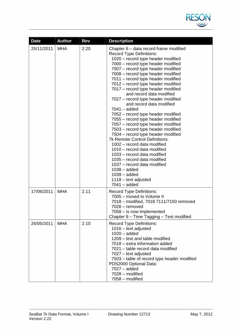
25/11/2011 MHA 2.20 Chapter 6 – data record frame modified Record Type Definitions: 1020 – record type header modified 7000 – record type header modified 7007 – record type header modified 7008 – record type header modified 7011 – record type header modified 7012 – record type header modified 7017 – record type header modified and record data modified 7027 – record type header modified and record data modified 7041 – added 7052 – record type header modified 7055 – record type header modified 7057 – record type header modified 7503 – record type header modified 7504 – record type header modified 7k Remote Control Definitions: 1002 – record data modified 1010 – record data modified 1033 – record data modified 1035 – record data modified 1037 – record data modified 1038 – added 1039 – added 1118 – text adjusted 7041 – added
17/06/2011 MHA 2.11 Record Type Definitions: 7005 – moved to Volume II 7018 – modified, 7018 7111/7150 removed 7026 – removed 7058 – is now implemented Chapter 9 – Time Tagging – Text modified
26/05/2011 MHA 2.10 Record Type Definitions: 1016 – text adjusted 1020 – added 1209 – text and table modified 7018 – extra information added 7021 – table record data modified 7027 – text adjusted 7503 – table of record type header modified PDS2000 Optional Data: 7027 – added 7028 – modified 7058 – modified

SeaBat 7k Data Format, Volume I Version 2.22
Drawing Number 12713 May 7, 2012
Date Author Rev Description
13/09/2010 MHA 2.00 The information updated with the latest information. The text checked and all the formats are now in line with the latest code.
11/05/2006 JM (MD) 1.00
08/11/2004 MJF (MD) 0.54
06/10/2004 MJF (MD) 0.53
19/07/2004 MJF (MD) 0.52
11/03/2004 MD Preliminary
SeaBat 7k Data Format, Volume I Version 2.22
Page i May 7, 2012
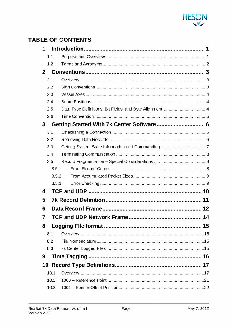
TABLE OF CONTENTS
1 Introduction .............................................................................. 1
1.1 Purpose and Overview .................................................................................. 1
1.2 Terms and Acronyms .................................................................................... 2
2 Conventions ............................................................................. 3
2.1 Overview ....................................................................................................... 3
2.2 Sign Conventions .......................................................................................... 3
2.3 Vessel Axes .................................................................................................. 4
2.4 Beam Positions ............................................................................................. 4
2.5 Data Type Definitions, Bit Fields, and Byte Alignment ................................... 4
2.6 Time Convention ........................................................................................... 5
3 Getting Started With 7k Center Software ............................... 6
3.1 Establishing a Connection ............................................................................. 6
3.2 Retrieving Data Records ............................................................................... 6
3.3 Getting System State Information and Commanding ..................................... 7
3.4 Terminating Communication ......................................................................... 8
3.5 Record Fragmentation – Special Considerations .......................................... 8
3.5.1 From Record Counts ............................................................................. 8
3.5.2 From Accumulated Packet Sizes ........................................................... 9
3.5.3 Error Checking ...................................................................................... 9
4 TCP and UDP ......................................................................... 10
5 7k Record Definition .............................................................. 11
6 Data Record Frame ................................................................ 12
7 TCP and UDP Network Frame ............................................... 14
8 Logging FIle format ............................................................... 15
8.1 Overview ......................................................................................................15
8.2 File Nomenclature ........................................................................................15
8.3 7k Center Logged Files ................................................................................15
9 Time Tagging ......................................................................... 16
10 Record Type Definitions ........................................................ 17
10.1 Overview ......................................................................................................17
10.2 1000 – Reference Point ...............................................................................21
10.3 1001 – Sensor Offset Position ......................................................................22

SeaBat 7k Data Format, Volume I Version 2.22
Page ii May 7, 2012
10.4 1002 – Sensor Offset Position Calibrated .....................................................22
10.5 1003 – Position ............................................................................................23
10.6 1004 – Custom Attitude Information .............................................................24
10.7 1005 – Tide ..................................................................................................26
10.8 1006 – Altitude .............................................................................................27
10.9 1007 – Motion Over Ground .........................................................................27
10.10 1008 – Depth ...............................................................................................28
10.11 1009 – Sound Velocity Profile ......................................................................28
10.12 1010 – CTD .................................................................................................29
10.13 1011 – Geodesy ...........................................................................................30
10.14 1012 – Roll Pitch Heave ...............................................................................32
10.15 1013 – Heading ............................................................................................32
10.16 1014 – Survey Line ......................................................................................33
10.17 1015 – Navigation ........................................................................................33
10.18 1016 – Attitude .............................................................................................34
10.19 1017 – Pan Tilt .............................................................................................35
10.20 1020 – Sonar Installation Identifiers .............................................................35
10.21 7000 – 7k Sonar Settings .............................................................................37
10.22 7001 – 7k Configuration ...............................................................................40
10.23 7002 – 7k Match Filter ..................................................................................42
10.24 7003 – 7k Firmware and Hardware Configuration ........................................43
10.25 7004 – 7k Beam Geometry ..........................................................................45
10.26 7006 – 7k Bathymetric Data .........................................................................46
10.27 7007 – 7k Side Scan Data ...........................................................................48
10.28 7008 – 7k Generic Water Column Data ........................................................49
10.29 7010 – TVG Values ......................................................................................53
10.30 7011 – 7k Image Data ..................................................................................54
10.31 7012 – 7k Ping Motion Data .........................................................................55
10.32 7017 – 7k Detection Data Setup ..................................................................56
10.33 7018 – 7k Beamformed Data .......................................................................59
10.34 7021 – 7k Built-In Test Environment Data ....................................................60
10.35 7022 – 7k Center Version ............................................................................64
10.36 7023 – 8k Wet End Version..........................................................................64
10.37 7027 – 7k RAW Detection Data ...................................................................64
10.38 7028 – 7k Snippet Data ................................................................................66

SeaBat 7k Data Format, Volume I Version 2.22
Page iii May 7, 2012
10.39 7041 – Compressed Beamformed Magnitude Data ......................................68
10.40 7048 – 7k Calibrated Beam Data .................................................................70
10.41 7050 – 7k System Events ............................................................................72
10.42 7051 – 7k System Event Message ...............................................................73
10.43 7052 – RDR Recording Status .....................................................................74
10.44 7053 – 7k Subscriptions ...............................................................................75
10.45 7055 – Calibration Status .............................................................................76
10.46 7057 – Calibrated Side-Scan Data ...............................................................77
10.47 7058 – Calibrated Snippet Data ...................................................................79
10.48 7200 – 7k File Header ..................................................................................82
10.49 7300 – 7k File Catalog Record .....................................................................82
10.50 7400 – 7k Time Message .............................................................................83
10.51 7500 – 7k Remote Control ...........................................................................83
10.52 7501 – 7k Remote Control Acknowledge .....................................................84
10.53 7502 – 7k Remote Control Not Acknowledge ...............................................84
10.54 7503 – Remote Control Sonar Settings ........................................................85
10.55 7504 – 7P Sensor Settings ..........................................................................89
10.56 7510 – SV Filtering ......................................................................................91
10.57 7511 – System Lock Status..........................................................................92
10.58 7610 – 7k Sound Velocity ............................................................................92
10.59 7611 – 7k Absorption Loss ...........................................................................93
10.60 7612 – 7k Spreading Loss ...........................................................................93
11 7k Remote Control Definitions .............................................. 94
11.1 Overview ......................................................................................................94
11.2 1000 – Shutdown .........................................................................................96
11.3 1001 – Reboot .............................................................................................96
11.4 1002 – 7k Center Calibration Control ...........................................................97
11.5 1003 – Range ..............................................................................................97
11.6 1004 – Max Ping Rate ..................................................................................97
11.7 1005 – Transmit Power ................................................................................97
11.8 1006 – Pulse Length ....................................................................................98
11.9 1007 – Pulse Type .......................................................................................98
11.10 1008 – Receiver Gain ..................................................................................98
11.11 1009 – Bottom Detection Mask ....................................................................99
11.12 1010 – Bottom Detection Filter Information ..................................................99
SeaBat 7k Data Format, Volume I Version 2.22
Page iv May 7, 2012
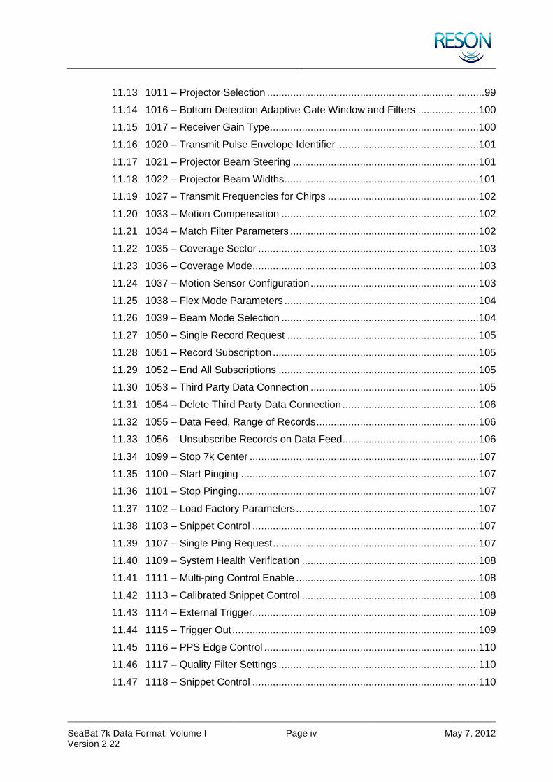
11.13 1011 – Projector Selection ...........................................................................99
11.14 1016 – Bottom Detection Adaptive Gate Window and Filters ..................... 100
11.15 1017 – Receiver Gain Type........................................................................ 100
11.16 1020 – Transmit Pulse Envelope Identifier ................................................. 101
11.17 1021 – Projector Beam Steering ................................................................ 101
11.18 1022 – Projector Beam Widths ................................................................... 101
11.19 1027 – Transmit Frequencies for Chirps .................................................... 102
11.20 1033 – Motion Compensation .................................................................... 102
11.21 1034 – Match Filter Parameters ................................................................. 102
11.22 1035 – Coverage Sector ............................................................................ 103
11.23 1036 – Coverage Mode .............................................................................. 103
11.24 1037 – Motion Sensor Configuration .......................................................... 103
11.25 1038 – Flex Mode Parameters ................................................................... 104
11.26 1039 – Beam Mode Selection .................................................................... 104
11.27 1050 – Single Record Request .................................................................. 105
11.28 1051 – Record Subscription ....................................................................... 105
11.29 1052 – End All Subscriptions ..................................................................... 105
11.30 1053 – Third Party Data Connection .......................................................... 105
11.31 1054 – Delete Third Party Data Connection ............................................... 106
11.32 1055 – Data Feed, Range of Records ........................................................ 106
11.33 1056 – Unsubscribe Records on Data Feed ............................................... 106
11.34 1099 – Stop 7k Center ............................................................................... 107
11.35 1100 – Start Pinging .................................................................................. 107
11.36 1101 – Stop Pinging ................................................................................... 107
11.37 1102 – Load Factory Parameters ............................................................... 107
11.38 1103 – Snippet Control .............................................................................. 107
11.39 1107 – Single Ping Request ....................................................................... 107
11.40 1109 – System Health Verification ............................................................. 108
11.41 1111 – Multi-ping Control Enable ............................................................... 108
11.42 1113 – Calibrated Snippet Control ............................................................. 108
11.43 1114 – External Trigger .............................................................................. 109
11.44 1115 – Trigger Out ..................................................................................... 109
11.45 1116 – PPS Edge Control .......................................................................... 110
11.46 1117 – Quality Filter Settings ..................................................................... 110
11.47 1118 – Snippet Control .............................................................................. 110

SeaBat 7k Data Format, Volume I Version 2.22
Page v May 7, 2012
11.48 1138 – Element Limit Control ..................................................................... 111
11.49 1200 – Start Recording .............................................................................. 112
11.50 1201 – Stop Recording / Playback ............................................................. 112
11.51 1202 – Start Playback ................................................................................ 112
11.52 1204 – Data Storage Status Request ......................................................... 113
11.53 1206 – Set Warning Threshold(s)............................................................... 113
11.54 1207 – Set Recording Directory ................................................................. 113
11.55 1209 – Set Filtering .................................................................................... 114
11.56 1400 – Autopilot Table Update ................................................................... 114
11.57 7041 – R7041 Setup .................................................................................. 115
11.58 7610 – Manual Sound Velocity ................................................................... 117
APPENDIX A PDS2000 Optional Data ..................................... 118
APPENDIX B Device Identifiers ............................................... 122
APPENDIX C Projection Identifiers ......................................... 124
APPENDIX D 7k Error Codes................................................... 126
SeaBat 7k Data Format, Volume I Version 2.22
Page vi May 7, 2012
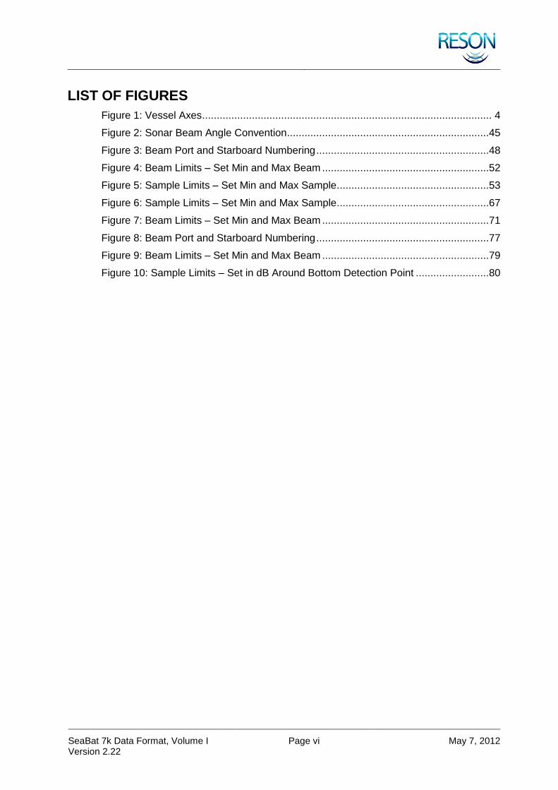
LIST OF FIGURES
Figure 1: Vessel Axes ................................................................................................... 4
Figure 2: Sonar Beam Angle Convention .....................................................................45
Figure 3: Beam Port and Starboard Numbering ...........................................................48
Figure 4: Beam Limits – Set Min and Max Beam .........................................................52
Figure 5: Sample Limits – Set Min and Max Sample ....................................................53
Figure 6: Sample Limits – Set Min and Max Sample ....................................................67
Figure 7: Beam Limits – Set Min and Max Beam .........................................................71
Figure 8: Beam Port and Starboard Numbering ...........................................................77
Figure 9: Beam Limits – Set Min and Max Beam .........................................................79
Figure 10: Sample Limits – Set in dB Around Bottom Detection Point .........................80

SeaBat 7k Data Format, Volume I Version 2.22
Page vii May 7, 2012
LIST OF TABLES
Table 1: Terms and Acronyms ...................................................................................... 2
Table 2: Sign Conventions ............................................................................................ 3
Table 3: Time Definition ................................................................................................ 5
Table 4: Version Concordance ..................................................................................... 6
Table 5: Data Record Frame .......................................................................................12
Table 6: Network Frame ..............................................................................................14
Table 7: Record Type Definitions .................................................................................17
Table 8: Available Record Types per 7k System .........................................................20
Table 9: 1000 – Record Type Header ..........................................................................21
Table 10: 1001 – Record Type Header ........................................................................22
Table 11: 1002 – Record Type Header ........................................................................22
Table 12: 1003 – Record Type Header ........................................................................23
Table 13: 1004 – Record Type Header ........................................................................25
Table 14: 1004 – Record Data .....................................................................................26
Table 15: 1005 – Record Type Header ........................................................................26
Table 16: 1006 – Record Type Header ........................................................................27
Table 17: 1007 – Record Type Header ........................................................................27
Table 18: 1007 – Record Data .....................................................................................28
Table 19: 1008 – Record Type Header ........................................................................28
Table 20: 1009 – Record Type Header ........................................................................28
Table 21: 1009 – Record Data .....................................................................................29
Table 22: 1010 – Record Type Header ........................................................................29
Table 23: 1010 – Record Data .....................................................................................30
Table 24: 1011 – Record Type Header ........................................................................30
Table 25: 1012 – Record Type Header ........................................................................32
Table 26: 1013 – Record Type Header ........................................................................32
Table 27: 1014 – Record Type Header ........................................................................33
Table 28: 1014 – Record Data .....................................................................................33
Table 29: 1015 – Record Type Header ........................................................................33
Table 30: 1016 – Record Type Header ........................................................................34
Table 31: 1016 – Record Data .....................................................................................34
Table 32: 1017 – Record Type Header ........................................................................35
Table 33: 1020 – Record Type Header ........................................................................35
Table 34: 7000 – Record Type Header ........................................................................37
SeaBat 7k Data Format, Volume I Version 2.22
Page viii May 7, 2012
Table 35: 7001 – Record Type Header ........................................................................40
Table 36: 7001 – Record Data .....................................................................................40
Table 37: 7002 – Record Type Header ........................................................................43
Table 38: 7003 – Record Type Header ........................................................................43
Table 39: 7004 – Record Type Header ........................................................................45
Table 40: 7004 – Record Data .....................................................................................46
Table 41: 7006 – Record Type Header ........................................................................46
Table 42: 7006 – Record Data .....................................................................................47
Table 43: 7007 – Record Type Header ........................................................................48
Table 44: 7007 – Record Data .....................................................................................49
Table 45: 7008 – Record Type Header ........................................................................50
Table 46: 7008 – Record Data (Part 1) ........................................................................51
Table 47: 7008 – Record Data (Part 2) ........................................................................52
Table 48: 7010 – Record Type Header ........................................................................53
Table 49: 7010 – Record Data .....................................................................................54
Table 50: 7011 – Record Type Header ........................................................................54
Table 51: 7011 – Record Data .....................................................................................54
Table 52: 7012 – Record Type Header ........................................................................55
Table 53: 7017 – Record Type Header ........................................................................56
Table 54: 7017 – Record Data .....................................................................................58
Table 55: 7017 – Detection Quality ..............................................................................59
Table 56: 7018 – Record Type Header ........................................................................59
Table 57: 7018 – Record Data .....................................................................................60
Table 58: 7021 – Record Type Header ........................................................................60
Table 59: 7021 – Record Data for Each Device (N) .....................................................61
Table 60: 7022 – Record Type Header ........................................................................64
Table 61: 7023 – Record Type Header ........................................................................64
Table 62: 7027 – Record Type Header ........................................................................64
Table 63: 7027 – Record Data .....................................................................................65
Table 64: 7027 – Detection Quality ..............................................................................66
Table 65: 7028 – Record Type Header ........................................................................67
Table 66: 7028 – Record Data .....................................................................................68
Table 67: 7041 – Record Type Header ........................................................................69
Table 68: 7041 – Record Data for Each Beam (B) .......................................................70
Table 69: 7048 – Record Type Header ........................................................................71

SeaBat 7k Data Format, Volume I Version 2.22
Page ix May 7, 2012
Table 70: 7048 – Record Data .....................................................................................72
Table 71: 7050 – Record Type Header ........................................................................72
Table 72: 7050 – Record Data .....................................................................................72
Table 73: 7051 – Record Type Header ........................................................................73
Table 74: 7051 – Record Data .....................................................................................73
Table 75: 7052 – Record Type Header ........................................................................74
Table 76: 7052 – Record Data .....................................................................................75
Table 77: 7053 – Record Type Header ........................................................................75
Table 78: 7053 – Record Data for Each Subscription (N) ............................................75
Table 79: 7055 – Record Type Header ........................................................................76
Table 80: 7057 – Record Type Header ........................................................................77
Table 81: 7057 – Record Data .....................................................................................78
Table 82: 7058 – Record Type Header ........................................................................80
Table 83: 7058 – Record Data .....................................................................................81
Table 84: 7200 – Record Type Header ........................................................................82
Table 85: 7200 – Record Data .....................................................................................82
Table 86: 7300 – Record Type Header ........................................................................82
Table 87: 7400 – Record Type Header ........................................................................83
Table 88: 7500 – Record Type Header ........................................................................83
Table 89: 7500 – Record Data .....................................................................................84
Table 90: 7501 – Record Type Header ........................................................................84
Table 91: 7502 – Record Type Header ........................................................................84
Table 92: 7503 – Record Type Header ........................................................................85
Table 93: 7504 – Record Type Header ........................................................................89
Table 94: 7510 – Record Type Header ........................................................................91
Table 95: 7511 – Record Type Header ........................................................................92
Table 96: 7610 – Record Type Header ........................................................................92
Table 97: 7611 – Record Type Header ........................................................................93
Table 98: 7612 – Record Type Header ........................................................................93
Table 99: 7k Remote Control Definitions .....................................................................94
Table 100: 7500 Record Data – Command 1002 .........................................................97
Table 101: 7500 Record Data – Command 1003 .........................................................97
Table 102: 7500 Record Data – Command 1004 .........................................................97
Table 103: 7500 Record Data – Command 1005 .........................................................97
Table 104: 7500 Record Data – Command 1006 .........................................................98

SeaBat 7k Data Format, Volume I Version 2.22
Page x May 7, 2012
Table 105: 7500 Record Data – Command 1007 .........................................................98
Table 106: 7500 Record Data – Command 1008 .........................................................98
Table 107: 7500 Record Data – Command 1009 .........................................................99
Table 108: 7500 Record Data – Command 1010 .........................................................99
Table 109: 7500 Record Data – Command 1011 ....................................................... 100
Table 110: 7500 Record Data – Command 1016 ....................................................... 100
Table 111: 7500 Record Data – Command 1016 ....................................................... 100
Table 112: 7500 Record Data – Command 1020 ....................................................... 101
Table 113: 7500 Record Data – Command 1021 ....................................................... 101
Table 114: 7500 Record Data – Command 1022 ....................................................... 101
Table 115: 7500 Record Data – Command 1027 ....................................................... 102
Table 116: 7500 Record Data – Command 1033 ....................................................... 102
Table 117: 7500 Record Data – Command 1034 ....................................................... 102
Table 118: 7500 Record Data – Command 1035 ....................................................... 103
Table 119: 7500 Record Data – Command 1036 ....................................................... 103
Table 120: 7500 Record Data – Command 1037 ....................................................... 103
Table 121: 7500 Record Data – Command 1038 ....................................................... 104
Table 122: 7500 Record Data – Command 1039 ....................................................... 104
Table 123: 7500 Record Data – Command 1050 ....................................................... 105
Table 124: 7500 Record Data – Command 1051 ....................................................... 105
Table 125: 7500 Record Data – Command 1053 ....................................................... 105
Table 126: 7500 Record Data – Command 1054 ....................................................... 106
Table 127: 7500 Record Data – Command 1055 ....................................................... 106
Table 128: 7500 Record Data – Command 1056 ....................................................... 106
Table 129: 7500 Record Data – Command 1103 ....................................................... 107
Table 130: 7500 Record Data – Command 1111 ....................................................... 108
Table 131: 7500 Record Data – Command 1113 ....................................................... 108
Table 132: 7500 Record Data – Command 1115 ....................................................... 109
Table 133: 7500 Record Data – Command 1116 ....................................................... 110
Table 134: 7500 Record Data – Command 1117 ....................................................... 110
Table 135: 7500 Record Data – Command 1118 ....................................................... 110
Table 136: 7500 Record Data – Command 1138 ....................................................... 111
Table 137: 7500 Record Data – Command 1200 ....................................................... 112
Table 138: 7500 Record Data – Command 1202 ....................................................... 112
Table 139: 7500 Record Data – Command 1206 ....................................................... 113

SeaBat 7k Data Format, Volume I Version 2.22
Page xi May 7, 2012
Table 140: 7500 Record Data – Command 1207 ....................................................... 113
Table 141: 7500 Record Data – Command 1209 ....................................................... 114
Table 142: 7500 Record Data – Command 1400 ....................................................... 114
Table 143: 7500 Record Data – Command 7041 ....................................................... 115
Table 144: 7500 Record Data – Command 7610 ....................................................... 117
Table 145: 7006 – Optional Data ............................................................................... 118
Table 146: 7007 – Optional Data ............................................................................... 118
Table 147: 7008 – Optional Data ............................................................................... 119
Table 148: 7027 – Optional Data ............................................................................... 119
Table 149: 7028 – Optional Data ............................................................................... 120
Table 150: 7057 – Optional Data ............................................................................... 120
Table 151: 7058 – Optional Data ............................................................................... 121
Table 152: Device Identifiers ..................................................................................... 122
Table 153: Projection Identifiers ................................................................................ 124

SeaBat 7k Data Format, Volume I Version 2.22
Page 1 May 7, 2012
1 INTRODUCTION
1.1 Purpose and Overview
This document describes the data format used to log and transmit network data using the RESON Application titled “7k Center.” The 7k Center is the primary interface to the sonar and provides auxiliary sensor support. It is included as standard software on all production units.
The 7k Data Format Definition document (DFD) defines record types relevant to the 7k series sonar. It also provides record definitions for generic sensors. This provides a robust, highly expandable generic wrapper format for sonar data in general, which includes all auxiliary sensors and information needed to completely describe data logged during a survey.
This record-based protocol encapsulates data using frames and headers. All records have a unique type identifier, and each record is wrapped within a frame that identifies and describes the content of the record.
A record’s embedded synchronization pattern, combined with its checksum, is a powerful aid in real time record validation and recovery from file corruption.
The data format also defines conventions pertaining to position, rotation, data types and time for consistent data handling.
SeaBat 7k Data Format, Volume I Version 2.22
Page 2 May 7, 2012
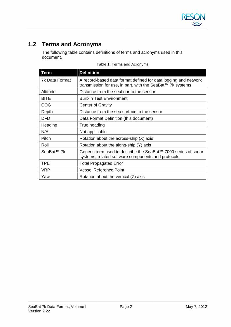
1.2 Terms and Acronyms
The following table contains definitions of terms and acronyms used in this document.
Table 1: Terms and Acronyms
Term Definition
7k Data Format A record-based data format defined for data logging and network transmission for use, in part, with the SeaBat™ 7k systems
Altitude Distance from the seafloor to the sensor
BITE Built-In Test Environment
COG Center of Gravity
Depth Distance from the sea surface to the sensor
DFD Data Format Definition (this document)
Heading True heading
N/A Not applicable
Pitch Rotation about the across-ship (X) axis
Roll Rotation about the along-ship (Y) axis
SeaBat™ 7k Generic term used to describe the SeaBat™ 7000 series of sonar systems, related software components and protocols
TPE Total Propagated Error
VRP Vessel Reference Point
Yaw Rotation about the vertical (Z) axis
SeaBat 7k Data Format, Volume I Version 2.22
Page 3 May 7, 2012
2 CONVENTIONS
2.1 Overview
This section describes the conventions and definitions used within this document.
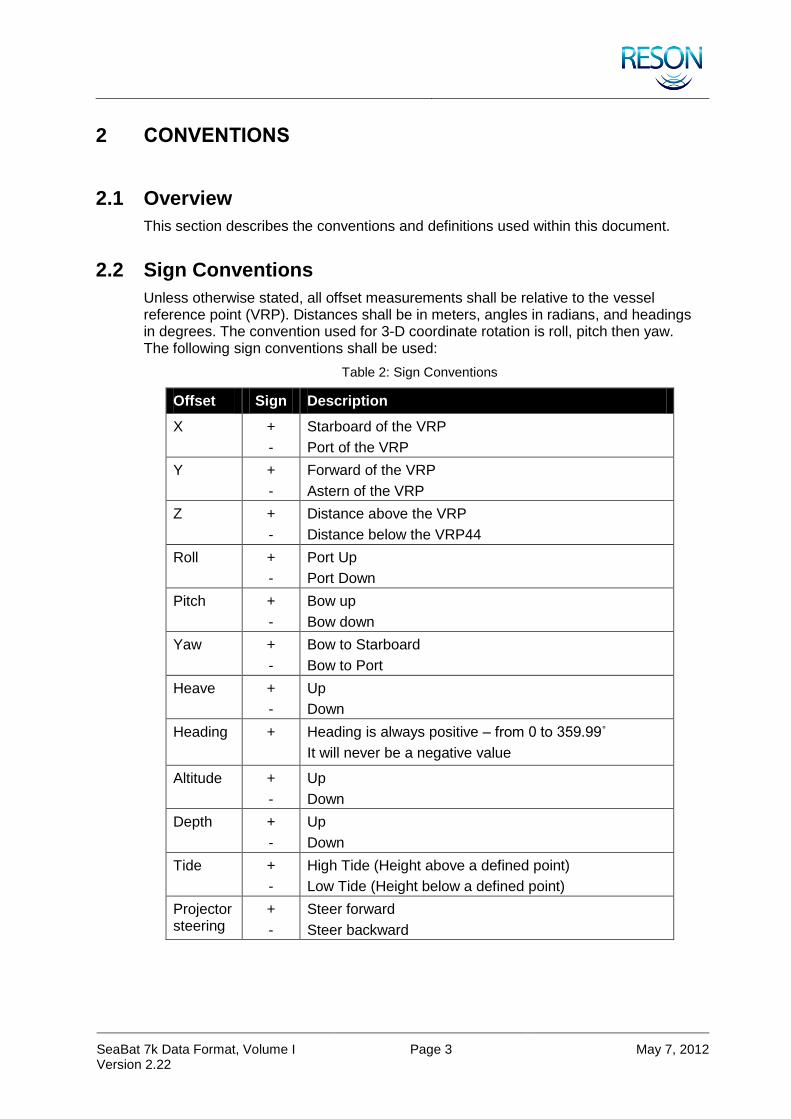
2.2 Sign Conventions
Unless otherwise stated, all offset measurements shall be relative to the vessel reference point (VRP). Distances shall be in meters, angles in radians, and headings in degrees. The convention used for 3-D coordinate rotation is roll, pitch then yaw. The following sign conventions shall be used:
Table 2: Sign Conventions
Offset Sign Description
X +
-
Starboard of the VRP
Port of the VRP
Y +
-
Forward of the VRP
Astern of the VRP
Z +
-
Distance above the VRP
Distance below the VRP44
Roll +
-
Port Up
Port Down
Pitch +
-
Bow up
Bow down
Yaw +
-
Bow to Starboard
Bow to Port
Heave +
-
Up
Down
Heading +
Heading is always positive – from 0 to 359.99˚
It will never be a negative value
Altitude +
-
Up
Down
Depth +
-
Up
Down
Tide +
-
High Tide (Height above a defined point)
Low Tide (Height below a defined point)
Projector steering
+
-
Steer forward
Steer backward

SeaBat 7k Data Format, Volume I Version 2.22
Page 4 May 7, 2012
2.3 Vessel Axes
Figure 1: Vessel Axes
2.4 Beam Positions
In a standard installation, beam zero represents the first beam on the port side of the sonar array. A reversed head mount system require the beam order be reversed by post processing software and may not need to be done in the 7k software.
Setting the "Projector Orientation" in the UI does NOT reorder beams in the data output.
2.5 Data Type Definitions, Bit Fields, and Byte Alignment
The following data type formats are defined by this document. Data shall be represented in little Endian (Intel) byte-order format unless stated otherwise.
Unsigned Integer Values: ‘uX’ is an unsigned integer, X bits wide. (e.g., u32 = unsigned 32 bits.)
Signed Integer Values: ‘iX’ is a signed integer, X bits wide. (e.g. i16 = signed 16 bits.)
Floating Points: Either f32 or f64 (IEEE 1754-1994).
Bit fields are frequently used in the data format. A bit field flag indicates whether a feature is activated or deactivated, or in some cases a value.

SeaBat 7k Data Format, Volume I Version 2.22
Page 5 May 7, 2012
All Record Type Headers are of static size and shall use “struct member alignment” of 1 byte in memory, also called “Single Byte Alignment”.
2.6 Time Convention
Time tags shall be in UTC unless stated otherwise and use the following structure:
Table 3: Time Definition
Name Size Description
Year u16 0-65535, all four digits must be used (for example, "2004" rather than "04")
Day u16 1-366
Seconds f32 0.000000-59.999999
Hours u8 0-23
Minutes u8 0-59
Also reference the 7KTIME definition in the Data Record Frame description as well as the general section regarding time stamping.
SeaBat 7k Data Format, Volume I Version 2.22
Page 6 May 7, 2012
3 GETTING STARTED WITH 7K CENTER SOFTWARE
3.1 Establishing a Connection
Two communication methods are available to the 7k Center: TCP/IP and UDP/IP. Before sending and receiving records to and from the 7k Center, a socket must be created and a connection to the 7k Center must be established.
A TCP socket must be connected in the sense that it negotiates an error-checking interaction with the socket in the 7k Center. A UDP socket is simpler to create, however it has no error checking or guaranteed delivery. With UDP, a socket is created, and then a record is sent to the IP address and port for the 7k Center to create a connection. TCP/IP is the recommended choice for communicating to the 7k Center application.
The standard port used by the 7k Center is 7000. All clients must initiate communication on this port.
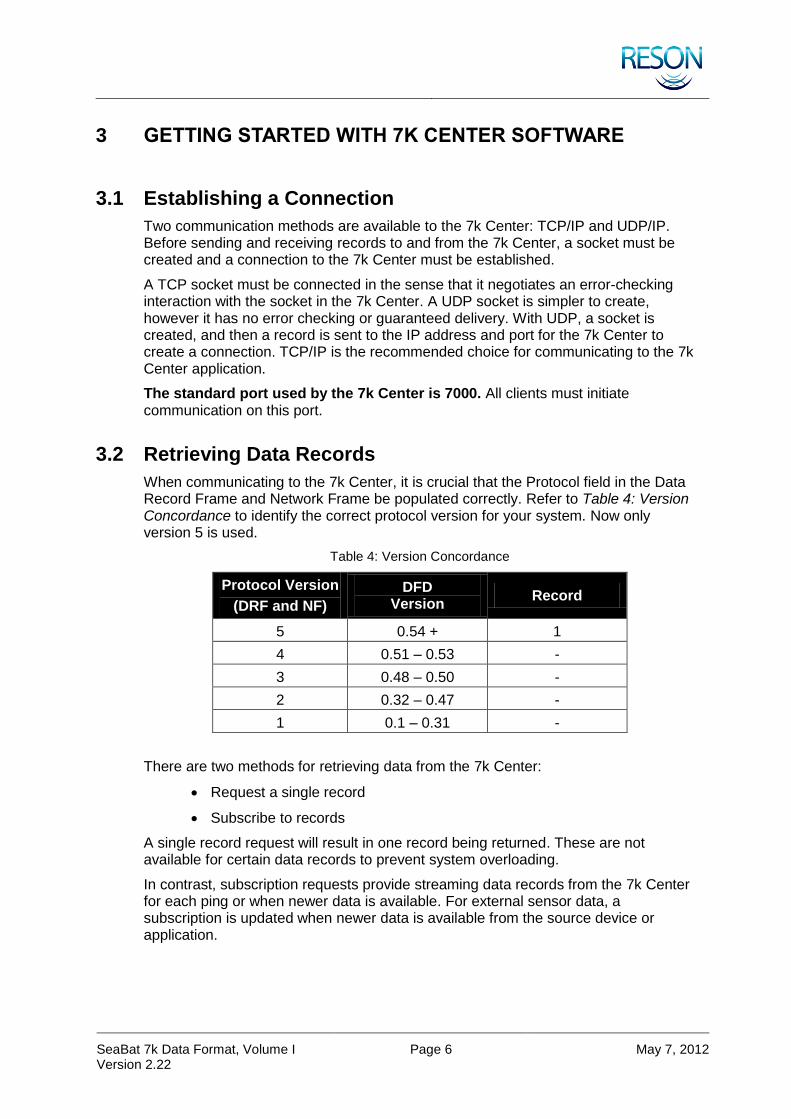
3.2 Retrieving Data Records
When communicating to the 7k Center, it is crucial that the Protocol field in the Data Record Frame and Network Frame be populated correctly. Refer to Table 4: Version Concordance to identify the correct protocol version for your system. Now only version 5 is used.
Table 4: Version Concordance
Protocol Version
(DRF and NF)
DFD Version
Record
5 0.54 + 1
4 0.51 – 0.53 -
3 0.48 – 0.50 -
2 0.32 – 0.47 -
1 0.1 – 0.31 -
There are two methods for retrieving data from the 7k Center:
Request a single record
Subscribe to records
A single record request will result in one record being returned. These are not available for certain data records to prevent system overloading.
In contrast, subscription requests provide streaming data records from the 7k Center for each ping or when newer data is available. For external sensor data, a subscription is updated when newer data is available from the source device or application.

SeaBat 7k Data Format, Volume I Version 2.22
Page 7 May 7, 2012
The following list defines the most common single record requests:
Configuration Data (7001)
System State (7503)
Data Storage Status (7052)
7k System Events (7050)
There are many records that can be subscribed to and requested. The following list provides some critical records needed for ping-to-ping logging and sonar data processing (this is system and user dependent):
7000 – Sonar settings
7004 – Beam geometry
7006 – Bottom detection results (bathymetric data)
7007 – Side-scan data
7018 – Beamformed data and snippet
7027 – Raw Bathymetry
7028 – Snippet
7051 – 7k System event messages
NOTE
If there are multiple devices attached to the 7k Center, you must subscribe to a specific set of records for each device using separate subscription requests.
3.3 Getting System State Information and Commanding
To obtain startup and system state information the client can request a single 7001. Because the requesting program is not expected to know what devices are attached until that record is received. The 7k Center will accept a device ID of 7000 and system enumerator 0 in the DRF/NF for this request.
When the 7001 record has been received, a listing of attached devices can be extracted from that record. The most important information for communication to the 7k Center is the device ID (such as “7101” or “7125”) and the system enumerator (always zero if there is only one device attached).
Following this client synchronization, a 7000 or 7503 (Sonar settings) record can be requested to get current system info for each attached device.
Record 7500 is the primary means of changing sonar settings (for a definition of the 7500 record, see section 10.51 7500 – 7k Remote Control). For a detailed description, see section 11 7k Remote Control Definitions. When commanding the sonar, you must supply a valid device ID and enumerator in the 7500’s Data Record Frame or the command will be rejected.
SeaBat 7k Data Format, Volume I Version 2.22
Page 8 May 7, 2012
NOTE
It is possible to bypass the configuration process and hard code the device ID values when deemed appropriate, for instance when simple data logging is needed with little commanding of the sonar.
3.4 Terminating Communication
The 7500/1053 command to the 7k Center will stop all subscriptions that match the information provided in the command record. The 1053 command is specific for each device, so a separate 7500/1053 must be sent for each device. The 7500/1053 command should be sent so that the 7k Center is in a well-known state and not still trying to send data to the requesting program. In the case of TCP, closing the socket will stop the data preparation; but UDP does not do so. UDP links must be explicitly terminated (see section 11 7k Remote Control Definitions).
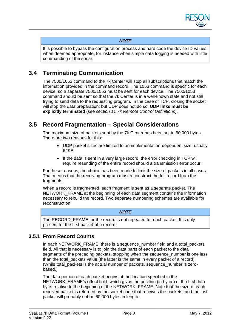
3.5 Record Fragmentation – Special Considerations
The maximum size of packets sent by the 7k Center has been set to 60,000 bytes. There are two reasons for this:
UDP packet sizes are limited to an implementation-dependent size, usually 64KB.
If the data is sent in a very large record, the error checking in TCP will require resending of the entire record should a transmission error occur.
For these reasons, the choice has been made to limit the size of packets in all cases. That means that the receiving program must reconstruct the full record from the fragments.
When a record is fragmented, each fragment is sent as a separate packet. The NETWORK_FRAME at the beginning of each data segment contains the information necessary to rebuild the record. Two separate numbering schemes are available for reconstruction.
NOTE
The RECORD_FRAME for the record is not repeated for each packet. It is only present for the first packet of a record.
3.5.1 From Record Counts
In each NETWORK_FRAME, there is a sequence_number field and a total_packets field. All that is necessary is to join the data parts of each packet to the data segments of the preceding packets, stopping when the sequence_number is one less than the total_packets value (the latter is the same in every packet of a record). (While total_packets is the actual number of packets, sequence_number is zero-based.)
The data portion of each packet begins at the location specified in the NETWORK_FRAME’s offset field, which gives the position (in bytes) of the first data byte, relative to the beginning of the NETWORK_FRAME. Note that the size of each received packet is returned by the socket code that receives the packets, and the last packet will probably not be 60,000 bytes in length.

SeaBat 7k Data Format, Volume I Version 2.22
Page 9 May 7, 2012
3.5.2 From Accumulated Packet Sizes
Reconstructing records from packet sizes is much like using record counts. The data sections are located and appended into a complete record as they are received. The accumulated data byte count is kept and compared to the total_size field of the NETWORK_FRAME (the same in each packet of a record). The record is complete when the accumulated size equals the total size.
3.5.3 Error Checking
Several error checks are possible on the incoming data. For TCP, there should be no transmission errors, but communications links could be dropped. For UDP, packets can be lost or appear out of order (but on small networks, that is extremely unlikely).
As each packet is received, the sequence numbers of the packets can be examined. Also, since all the packets except for the final one are of known size (data section 60,000 bytes less the size of the NETWORK_FRAME), the accumulated size that should be present for a given sequence number can be easily verified to see if packets have been lost.
These assume that the data are all present and are all in order and that no fragments of one fragmented record arrive interspersed between packets of another fragmented record. While this is a reasonable assumption on a small network, it is not necessarily true in general.

SeaBat 7k Data Format, Volume I Version 2.22
Page 10 May 7, 2012
4 TCP AND UDP
TCP sessions should conform to RFC 793 extensions. UDP session should conform to RFC 768 and later extensions.
Unless otherwise stated, TCP connections should not use the Nagle algorithm to minimize network latency.
Both source and destination port must be populated with a unique port number for TCP and UDP transmissions.

SeaBat 7k Data Format, Volume I Version 2.22
Page 11 May 7, 2012
5 7K RECORD DEFINITION
A 7k record consists of a data record frame, a record type header, an optional record data section, and an optional data section for extra information. The Record Data section is considered optional because some remote controls commands consist only of the RTH.
The optional data field typically holds sensor-specific data and third party developer embedded data.
When 7k records are transmitted over a network, a network frame shall precede each record.
Please note that the Checksum is a required portion of the DRF, which occurs as the last four bytes of every record.
7k RECORD
DRF – Data Record Frame
RTH – Record Type Header
RD – Record Data
OD – Optional Data
Network prepared with the Network Frame (NF).

SeaBat 7k Data Format, Volume I Version 2.22
Page 12 May 7, 2012
6 DATA RECORD FRAME
The Data Record Frame (DRF) is the wrapper in which all records (sensor data or otherwise) shall be embedded. The sync pattern combined with the checksum should aid recovery in the event a file becomes corrupted. A record frame shall always start with the version and offset fields and can be used to dynamically determine the protocol version, if necessary.
The frame is defined as follows:
Table 5: Data Record Frame
Name Size Description
Protocol Version u16 Protocol version of this frame (see Table 4: Version Concordance)
Offset u16 Offset in bytes from the start of the sync pattern to the start of the Record Type Header (RTH). This allows for expansion of the header whilst maintaining backward compatibility.
Sync pattern u32 0x0000FFFF
Size u32 Size in bytes of this record from the start of the Protocol version field to the end of the checksum field — including any embedded data
Optional data offset u32 Offset in bytes to optional data field from start of record. Zero (0) bytes implies no optional data.
Optional data identifier u32 User defined
7KTIME u8 * 10 Time tag indicating when data was produced
Reserved u16 Reserved
Record type identifier u32 Identifier for record type of embedded data
Device identifier u32 Identifier of the device to which this data pertains
System enumerator u32 The enumerator is used to differentiate between devices with the same device identifiers in one installation/system. It is up to each application to decide what number to populate this field with.
Reserved u32 Reserved

SeaBat 7k Data Format, Volume I Version 2.22
Page 13 May 7, 2012
Name Size Description
Flags u16 BIT FIELD:
Bit 0: Checksum
0 – Invalid checksum
1 – Valid checksum
Bit 1: Broadcast
1 – Enabled
Bit 2-14: Reserved (must be zero)
Bit 15:
0 – Live data
1 – Recorded data
Reserved u16 Reserved
Reserved u32 Reserved
Total records in fragmented data record set
u32 Total records in fragmented data record set (if appropriate flag is set)
Fragment number u32 Fragment number (if appropriate flag is set)
DATA SECTION Dynamic Data section
Checksum u32 Sum of all byte values (treated as unsigned) in the record from the beginning of the version field to the end of the data section. The use of this field is optional and depends on bit 1 of the Flags field. The checksum should be computed as a 32 bit unsigned integer.

SeaBat 7k Data Format, Volume I Version 2.22
Page 14 May 7, 2012
7 TCP AND UDP NETWORK FRAME
Records will be packetized using the following prefixed header for both the TCP and UDP/IP protocols. Packet sizes may not vary in a sequence, except for the last packet.
When using UDP protocol, each packet shall be less than or equal to 64K bytes, including the network header.
The following header shall prefix the network packet:
Table 6: Network Frame
Name Size Description
Protocol version u16 Protocol version of this frame (see Table 4: Version Concordance)
Offset u16 Offset in bytes to the start of data from the start of this packet
Total packets u32 Number of network packets for set of records transmitted (always 1)
Total records u16 Total number of records in network packets transmitted (helper field for parsing data). Max 128 records per transmission (always 1).
Transmission identifier u16 Transmission identifier (helper field for packet assembly). Must be the same number for each network packet in transmission. Adjacent transmissions in time from one source may not use the same identifier (always 1).
Packet size u32 Size in bytes of this packet including the header and appended data
Total size u32 Total size in bytes of all packets in transmission, excluding network frame(s)
Sequence number u32 Sequential packet number; allows correct ordering during reconstruction. Range = 0 to n-1 packets
Destination device identifier
u32 0 – Unspecified
0xFFFFFFFF – Not used
Any other number is a valid address
Destination enumerator u16 Destination enumerator unless destination device identifier is unspecified or not used
Source enumerator u16 Source enumerator unless Source Device Identifier is unspecified or not used
Source device identifier u32 0 – Unspecified
0xFFFFFFFF – Not used
Any other number is a valid address

SeaBat 7k Data Format, Volume I Version 2.22
Page 15 May 7, 2012
8 LOGGING FILE FORMAT
8.1 Overview
A valid 7k data file shall be a binary file consisting of a series of data records conforming to the conventions and definitions in this document.
Records must be complete and without the network frame.
A file header record (7200) is recommended to be the first record in each file. This file describes the file’s contents.
8.2 File Nomenclature
It is recommended that file names be based on the UTC date and time when they are created and utilize an ‘.s7k’ extension as follows:
“YYYYMMDD_HHMMSS.s7k”
With:
YYYY = Year MM = Month DD = Day HH = Hour MM = Minutes SS = Seconds
For example, 20100516_102852.s7k (Created May 16, 2010 at 10:28:52)
When using third party logging tools, multiple files created at the same time can be differentiated by appending _X to the filename (where “X” is an integer starting at zero and successively incremented for each file).
For example, 20100516_102852_0.s7k and 20100516_102852_1.s7k
8.3 7k Center Logged Files
The 7k Center logs data in order it is received. In the case of sonar data, this guarantees that the pings are logged in sequential (and therefore chronological) order. In general, however, the data in a log file cannot be guaranteed to be in chronological order.
Record 7052 (7K Data Storage Status) can be used to determine which records are available and current record logging filters. Remote command 1209 (Set Filtering) is used to set the record logging filters.
Complete files generated using RESON 7k Center software will always begin with a 7200 record and will usually be followed by a 7001 record and contain a 7300 record as the last record in the file. This record is for RESON diagnostic use only.
Incoming 7k Remote Controls (record 7500) are not logged in 7k files generated by the 7k Center. Remote controls activity is stored in a separate log file. These files are for RESON diagnostic use only. Network Frames are also not logged.
The default extension for 7k Center logged files is *.s7k, where the ‘*’ represents the filename.

SeaBat 7k Data Format, Volume I Version 2.22
Page 16 May 7, 2012
9 TIME TAGGING
Through the IO Module the time of the system has to be synced with a PPS and a time message from a GPS (for instance a ZDA message).
Time tags reside in the DRF for each record. The time stamp in the record is always the time at which the data, contained in the record, was generated. It does not refer to the time that the record was formatted or sent.
For ping related records, the time stamp refers to the time when the sonar transmitter finishes a ping.
The time stamping for messages received from a sensor depends on the selected driver in the IO Module. In general, the position will use time in message and other sensors use time of arrival of the first character. For some sensors (e.g POS MV), the time will be time in message; the time as is defined in the message string.
SeaBat 7k Data Format, Volume I Version 2.22
Page 17 May 7, 2012
10 RECORD TYPE DEFINITIONS
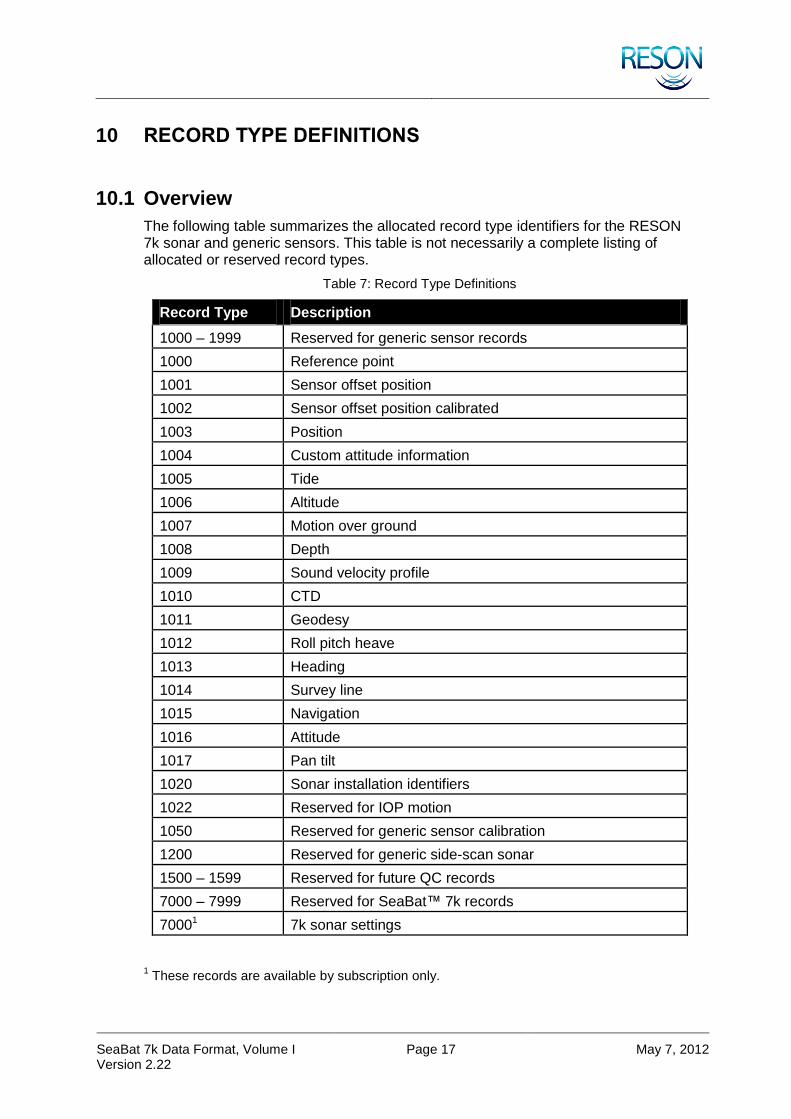
10.1 Overview
The following table summarizes the allocated record type identifiers for the RESON 7k sonar and generic sensors. This table is not necessarily a complete listing of allocated or reserved record types.
Table 7: Record Type Definitions
Record Type Description
1000 – 1999 Reserved for generic sensor records
1000 Reference point
1001 Sensor offset position
1002 Sensor offset position calibrated
1003 Position
1004 Custom attitude information
1005 Tide
1006 Altitude
1007 Motion over ground
1008 Depth
1009 Sound velocity profile
1010 CTD
1011 Geodesy
1012 Roll pitch heave
1013 Heading
1014 Survey line
1015 Navigation
1016 Attitude
1017 Pan tilt
1020 Sonar installation identifiers
1022 Reserved for IOP motion
1050 Reserved for generic sensor calibration
1200 Reserved for generic side-scan sonar
1500 – 1599 Reserved for future QC records
7000 – 7999 Reserved for SeaBat™ 7k records
70001 7k sonar settings
1 These records are available by subscription only.
SeaBat 7k Data Format, Volume I Version 2.22
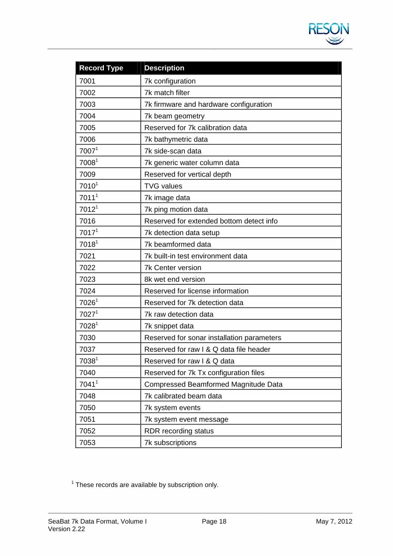
Page 18 May 7, 2012
Record Type Description
7001 7k configuration
7002 7k match filter
7003 7k firmware and hardware configuration
7004 7k beam geometry
7005 Reserved for 7k calibration data
7006 7k bathymetric data
70071 7k side-scan data
70081 7k generic water column data
7009 Reserved for vertical depth
70101 TVG values
70111 7k image data
70121 7k ping motion data
7016 Reserved for extended bottom detect info
70171 7k detection data setup
70181 7k beamformed data
7021 7k built-in test environment data
7022 7k Center version
7023 8k wet end version
7024 Reserved for license information
70261 Reserved for 7k detection data
70271 7k raw detection data
70281 7k snippet data
7030 Reserved for sonar installation parameters
7037 Reserved for raw I & Q data file header
70381 Reserved for raw I & Q data
7040 Reserved for 7k Tx configuration files
70411 Compressed Beamformed Magnitude Data
7048 7k calibrated beam data
7050 7k system events
7051 7k system event message
7052 RDR recording status
7053 7k subscriptions
1 These records are available by subscription only.

SeaBat 7k Data Format, Volume I Version 2.22
Page 19 May 7, 2012
Record Type Description
7055 Normalization status
7057 Calibrated side-scan data
7058 Calibrated snippet data
7060 Reserved for 7k target data
70681 Reserved
7200 7k file header
7300 7k file catalogue record
7310 Reserved for 7k trigger
7311 Reserved for 7k trigger sequence setup
7312 Reserved for 7k trigger sequence done
7400 7k time message
7401 – 7499 Reserved for future time messages
7500 7k remote control
7501 7k remote control acknowledge
7502 7k remote control not acknowledge
7503 7k remote control sonar settings
7504 7P sensor settings
7505 Reserved
7511 System lock status
7515 Timestamp (not described in the documentation)
7610 7k sound velocity
7611 7k absorption loss
7612 7k spreading loss
7613 Reserved
7900 – 7999 Reserved
80121 Pitch, yaw, heave flag (not described in the documentation)
8100 8k series sonar data (not described in the documentation)
11000 – 11299 Reserved
81000 – 87999 Reserved
Not all records shown in this section are available for all systems. Availability of certain records will depend on the specific installation. In most cases, only SeaBat™ relevant data is produced from the 7k Center.
1 These records are available by subscription only.

SeaBat 7k Data Format, Volume I Version 2.22
Page 20 May 7, 2012
The record types mentioned below in the table are the record types that are logged for the different 7k systems.
Table 8: Available Record Types per 7k System
Record Types
7k Systems
7100
7101
7111
7112
7122
7123
7125
7128
7130
7150
8125H
1000 x x x x x x x x x x x
1001 x x x x x x x x x x x
1002 x x x x x x x x x x x
1003 x x x x x x x x x x x
1004 x x x x x x x x x x x
1005 x x x x x x x x x x x
1006 x x x x x x x x x x x
1007 x x x x x x x x x x x
1008 x x x x x x x x x x x
1009 x x x x x x x x x x x
1010 x x x x x x x x x x x
1011 x x x x x x x x x x x
1012 x x x x x x x x x x x
1013 x x x x x x x x x x x
1014 x x x x x x x x x x x
1015 x x x x x x x x x x x
1016 x x x x x x x x x x x
1017 x x x x x x x x x x x
1050 x x x x x x x x x x x
7000 x x x x x x x x x x x
7001 x x x x x x x x x x x
7002 x x x x x x x x x
7004 x x x x x x x x x x x
7006 x x x x x x x x
7007 x x x x x x x x
7008 x x x x x x x x x x x
7010 x x x x x x x x x x x
7011 x x x x x x x x x x x
7012 x x x x x x x
7017 x x x x x x

SeaBat 7k Data Format, Volume I Version 2.22
Page 21 May 7, 2012
Record Types
7k Systems
7100
7101
7111
7112
7122
7123
7125
7128
7130
7150
8125H
7018 x x x x x x x x x x x
7021 x x x x x x x x x x x
7022 x x x x x x x x
7027 x x x x x x
7028 x x x x x x x
7038 x x x x
7039 x x x
7041 x
7048 x x x
7057 x x x
7058 x x x
7068 x x
7200 x x x x x x x x x x x
7300 x x x x x x x
7400 x
7500 x
7503 x x x x x x x x x x x
7504 x x x x x x x x
7505 x x
7511 x x x x x x x x x
7610 x x x x x x
7611 x x x x x x
7612 x x x x x x
10.2 1000 – Reference Point
Description: Reference point Information.
Data Definition:
DRF RTH RD OD DRF
Table 9: 1000 – Record Type Header
Name Size Description
Vehicle’s X reference point to center of gravity f32 X offset in meters
Vehicle’s Y reference point to center of gravity f32 Y offset in meters
Vehicle’s Z reference point to center of gravity f32 Z offset in meters
SeaBat 7k Data Format, Volume I Version 2.22
Page 22 May 7, 2012
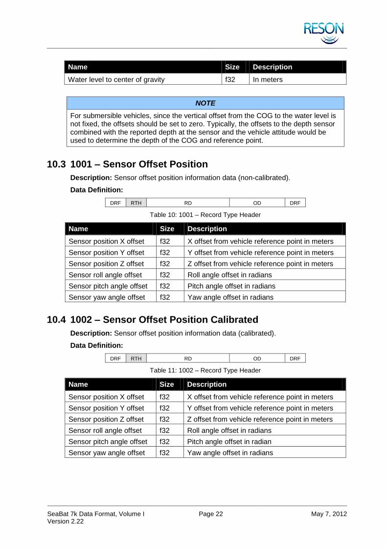
Name Size Description
Water level to center of gravity f32 In meters
NOTE
For submersible vehicles, since the vertical offset from the COG to the water level is not fixed, the offsets should be set to zero. Typically, the offsets to the depth sensor combined with the reported depth at the sensor and the vehicle attitude would be used to determine the depth of the COG and reference point.
10.3 1001 – Sensor Offset Position
Description: Sensor offset position information data (non-calibrated).
Data Definition:
DRF RTH RD OD DRF
Table 10: 1001 – Record Type Header
Name Size Description
Sensor position X offset f32 X offset from vehicle reference point in meters
Sensor position Y offset f32 Y offset from vehicle reference point in meters
Sensor position Z offset f32 Z offset from vehicle reference point in meters
Sensor roll angle offset f32 Roll angle offset in radians
Sensor pitch angle offset f32 Pitch angle offset in radians
Sensor yaw angle offset f32 Yaw angle offset in radians
10.4 1002 – Sensor Offset Position Calibrated
Description: Sensor offset position information data (calibrated).
Data Definition:
DRF RTH RD OD DRF
Table 11: 1002 – Record Type Header
Name Size Description
Sensor position X offset f32 X offset from vehicle reference point in meters
Sensor position Y offset f32 Y offset from vehicle reference point in meters
Sensor position Z offset f32 Z offset from vehicle reference point in meters
Sensor roll angle offset f32 Roll angle offset in radians
Sensor pitch angle offset f32 Pitch angle offset in radian
Sensor yaw angle offset f32 Yaw angle offset in radians

SeaBat 7k Data Format, Volume I Version 2.22
Page 23 May 7, 2012
10.5 1003 – Position
Description: Position Record used in conjunction with Record Type 1011.
Data Definition:
DRF RTH RD OD DRF
Table 12: 1003 – Record Type Header
Name Size Description
Datum identifier u32 0 – WGS84
>0 – Reserved
Latency f32 In seconds
Latitude or northing f64 Latitude in radians or northing in meters
Longitude or easting f64 Longitude in radians or easting in meters
Height relative to datum or height
f64 In meters
Position type flag u8 0 – Geographical coordinates
1 – Grid coordinates
UTM zone u8 UTM Zone
Quality flag u8 0 – Navigation Data
1 – Dead-Reckoning
Positioning method u8 0 – GPS
1 – DGPS
2 – Start of inertial positioning system from GPS
3 – Start of inertial positioning system from DGPS
4 – Start of inertial positioning system from bottom correlation
5 – Start of inertial positioning from bottom object
6 – Start of inertial positioning from inertial positioning
7 – Start of inertial positioning from optional data
8 – Stop of inertial positioning system to GPS
Positioning method (cont.) u8 9 – Stop of inertial positioning system to DGPS
10 – Stop of inertial positioning system to bottom correlation
11 – Stop of inertial positioning to bottom object
12 – Start of inertial positioning to inertial positioning
13 – Start of inertial positioning to optional data
14 – User defined

SeaBat 7k Data Format, Volume I Version 2.22
Page 24 May 7, 2012
10.6 1004 – Custom Attitude Information
Description: Attitude Data Record. The length of this record is dynamic and is based on the field mask. The bit field mask determines which elements make up a sample of fields in a given record. The number of samples (N) determines how many samples are repeated in a record at the specified sample rate (Frequency).
NOTE
This is a custom field designed for advanced users who have specific needs. Normally, records 1012 and 1013 will be used.

SeaBat 7k Data Format, Volume I Version 2.22
Page 25 May 7, 2012
Data Definition:
DRF RTH RD OD DRF
Table 13: 1004 – Record Type Header
Name Size Description
Field mask u8 BIT FIELD:
Bit 0:
0 – No pitch
1 – Pitch in radians
Bit 1:
0 – No roll
1 – Roll in radians
Bit 2:
0 – No heading
1 – Heading in radians
Bit 3:
0 – No heave
1 – Heave in meters
Bit 4:
0 – No pitch
1 – Pitch rate of change in radians per second
Bit 5:
0 – No roll rate
1 – Roll rate of change in radians per second
Bit 6:
0 – No heading rate
1 – Heading ate of change in radians per second
Bit 7:
0 – No heave rate
1 – Heave rate of change in meters per second
Reserved u8 Reserved
N u16 Number of repeated fields in the record
Frequency f32 Sample rate in samples / second (required if multiple samples are used per record)

SeaBat 7k Data Format, Volume I Version 2.22
Page 26 May 7, 2012
DRF RTH RD OD DRF
Table 14: 1004 – Record Data
Name Size Description
FIELD 0 f32 Sensor data
… … ...
FIELD N-1 f32 Sensor data
10.7 1005 – Tide
Description: Tide Data Record. Supports either measured or predicted tide values.
NOTE
Only the tide value and its source (the first two fields) in the RTH are mandatory; positional information is optional and may be set to zero.
Data Definition:
DRF RTH RD OD DRF
Table 15: 1005 – Record Type Header
Name Size Description
Tide f32 Height correction above mean sea level in meters
Source u16 0 – Unspecified
1 – Table (predicted)
2 – Measured (gauge)
Flags u8 BIT FIELD:
Bit 0:
0 – Gauge ID invalid
1 – Gauge ID valid
Bit 1:
0 – Position info invalid
1 – Position info valid
Gauge identifier u16 User defined
Datum identifier u32 0 – WGS84
>0 – Reserved
Latency f32 In seconds
Latitude or northing f64 Latitude in radians or northing in meters
Longitude or easting f64 Longitude in radians or easting in meters
Height relative to datum or height
f64 In meters
SeaBat 7k Data Format, Volume I Version 2.22
Page 27 May 7, 2012
Name Size Description
Position type flag u8 0 – Geographical coordinates
1 – Grid coordinates
UTM zone u8 UTM zone
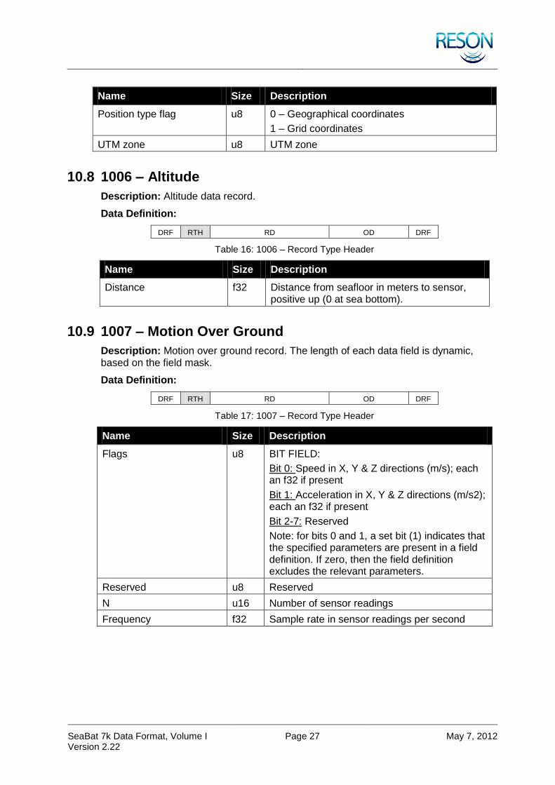
10.8 1006 – Altitude
Description: Altitude data record.
Data Definition:
DRF RTH RD OD DRF
Table 16: 1006 – Record Type Header
Name Size Description
Distance f32 Distance from seafloor in meters to sensor, positive up (0 at sea bottom).
10.9 1007 – Motion Over Ground
Description: Motion over ground record. The length of each data field is dynamic, based on the field mask.
Data Definition:
DRF RTH RD OD DRF
Table 17: 1007 – Record Type Header
Name Size Description
Flags u8 BIT FIELD:
Bit 0: Speed in X, Y & Z directions (m/s); each an f32 if present
Bit 1: Acceleration in X, Y & Z directions (m/s2); each an f32 if present
Bit 2-7: Reserved
Note: for bits 0 and 1, a set bit (1) indicates that the specified parameters are present in a field definition. If zero, then the field definition excludes the relevant parameters.
Reserved u8 Reserved
N u16 Number of sensor readings
Frequency f32 Sample rate in sensor readings per second

SeaBat 7k Data Format, Volume I Version 2.22
Page 28 May 7, 2012
DRF RTH RD OD DRF
Table 18: 1007 – Record Data
Name Size Description
Reading 0 Variable (3x f32 or 6x f32) Motion data
… … ...
Reading N-1 variable (3x f32 or 6x f32) Motion data
10.10 1008 – Depth
Description: Depth data record.
Data Definition:
DRF RTH RD OD DRF
Table 19: 1008 – Record Type Header
Name Size Description
Depth descriptor u8 0 – Depth to sensor
1 – Water depth
Correction flag u8 0 – RAW depth (as measured)
1 – Corrected depth (relative to mean-sea level)
Reserved u16 Reserved
Depth f32 The deeper, the bigger (positive) this value becomes
10.11 1009 – Sound Velocity Profile
Description: Sound velocity profile data record.
Data Definition:
DRF RTH RD OD DRF
Table 20: 1009 – Record Type Header
Name Size Description
Position flag u8 0 – Invalid position fields
1 – Valid position fields
Reserved u8 Reserved
Reserved u16 Reserved
Latitude f64 Latitude in radians (WGS84)
Longitude f64 Longitude in radians (WGS84)
N u32 Number of samples

SeaBat 7k Data Format, Volume I Version 2.22
Page 29 May 7, 2012
DRF RTH RD OD DRF
Table 21: 1009 – Record Data
Name Size Description
SAMPLE 0 depth f32 In meters
SAMPLE 0 sound velocity f32 In meters/second
… … ...
SAMPLE N-1 depth f32 In meters
SAMPLE N-1 sound velocity f32 In meters/second
10.12 1010 – CTD
Description: CTD Data Record
Data Definition:
DRF RTH RD OD DRF
Table 22: 1010 – Record Type Header
Name Size Description
Frequency f32 Frequency
Sound velocity source flag u8 0 – Not computed
1 – CTD
2 – User computed
Sound velocity algorithm u8 0 – Not computed
1 – Chen Millero
2 – Del Grosso
Conductivity flag u8 0 – Conductivity
1 – Salinity
Pressure flag u8 0 – Pressure
1 – Depth
Position flag u8 0 – Invalid position fields
1 – Valid position fields
Sample content validity u8 BIT FIELD:
(Bit set means field is valid otherwise zero)
Bit 0: Conductivity/Salinity
Bit 1: Water temperature
Bit 2: Pressure/Depth
Bit 3: Sound velocity
Bit 4: Absorption
Reserved u16 Reserved
Latitude f64 Latitude in radians (WGS84)
Longitude f64 Longitude in radians (WGS84)

SeaBat 7k Data Format, Volume I Version 2.22
Page 30 May 7, 2012
Name Size Description
Sample rate f32 Sample rate
N u32 Number of samples
DRF RTH RD OD DRF
Table 23: 1010 – Record Data
Name Size Description
SAMPLE 0 Conductivity/Salinity f32 In S/m or ppt
SAMPLE 0 Water temperature f32 In Celsius
SAMPLE 0 Pressure/Depth f32 In Pascal or meters
SAMPLE 0 Sound velocity f32 In meters/seconds
SAMPLE 0 Absorption f32 In dB/kilometer
… … ...
SAMPLE N-1 Conductivity/Salinity f32 In S/m or ppt
SAMPLE N-1 Water temperature f32 In Celsius
SAMPLE N-1 Pressure/Depth f32 In Pascal or meters
SAMPLE N-1 Sound velocity f32 In meters/seconds
SAMPLE N-1 Absorption f32 In dB/kilometer
10.13 1011 – Geodesy
Description: The Geodesy data record may be used to define the spheroid, datum, and grid definitions for navigational data; each sequentially embedded within the RTH. The optional data portion of the record is used to contain custom projection parameters.
Data Definition:
DRF RTH RD OD DRF
Table 24: 1011 – Record Type Header
Name Size Description
Spheroid name u8 * 32 A short text description of the spheroid name: e.g. “WGS84”
Semi-major axis f64 Semi-major axis in meters: e.g., 6378137.0 for WGS84
Inverse flattening f64 Inverse flattening in meters: e.g. 298.257223563 for WGS84
Reserved 1 u8 * 16 Reserved
Datum name u8 * 32 Datum name: e.g. “WGS84”
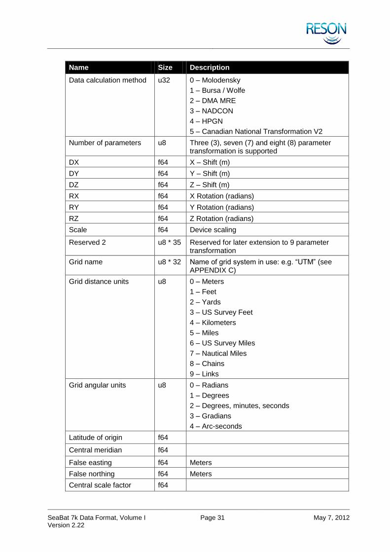
SeaBat 7k Data Format, Volume I Version 2.22
Page 31 May 7, 2012
Name Size Description
Data calculation method u32 0 – Molodensky
1 – Bursa / Wolfe
2 – DMA MRE
3 – NADCON
4 – HPGN
5 – Canadian National Transformation V2
Number of parameters u8 Three (3), seven (7) and eight (8) parameter transformation is supported
DX f64 X – Shift (m)
DY f64 Y – Shift (m)
DZ f64 Z – Shift (m)
RX f64 X Rotation (radians)
RY f64 Y Rotation (radians)
RZ f64 Z Rotation (radians)
Scale f64 Device scaling
Reserved 2 u8 * 35 Reserved for later extension to 9 parameter transformation
Grid name u8 * 32 Name of grid system in use: e.g. “UTM” (see APPENDIX C)
Grid distance units u8 0 – Meters
1 – Feet
2 – Yards
3 – US Survey Feet
4 – Kilometers
5 – Miles
6 – US Survey Miles
7 – Nautical Miles
8 – Chains
9 – Links
Grid angular units u8 0 – Radians
1 – Degrees
2 – Degrees, minutes, seconds
3 – Gradians
4 – Arc-seconds
Latitude of origin f64
Central meridian f64
False easting f64 Meters
False northing f64 Meters
Central scale factor f64
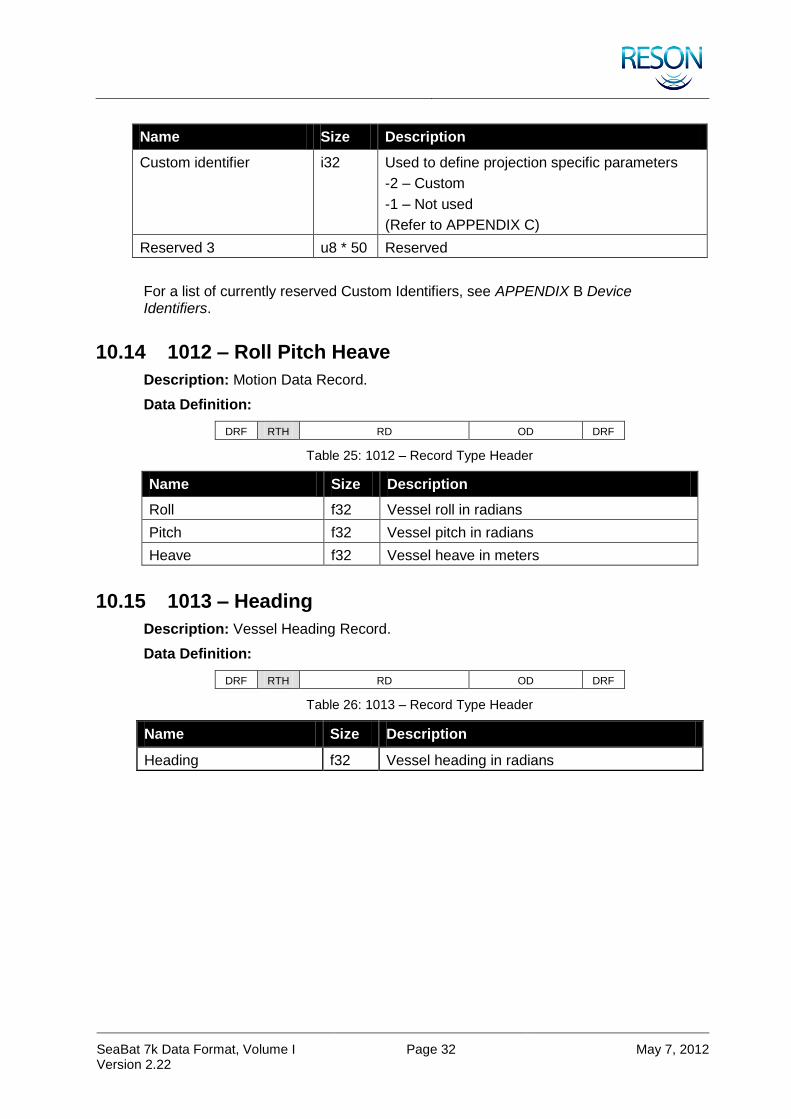
SeaBat 7k Data Format, Volume I Version 2.22
Page 32 May 7, 2012
Name Size Description
Custom identifier i32 Used to define projection specific parameters
-2 – Custom
-1 – Not used
(Refer to APPENDIX C)
Reserved 3 u8 * 50 Reserved
For a list of currently reserved Custom Identifiers, see APPENDIX B Device Identifiers.
10.14 1012 – Roll Pitch Heave
Description: Motion Data Record.
Data Definition:
DRF RTH RD OD DRF
Table 25: 1012 – Record Type Header
Name Size Description
Roll f32 Vessel roll in radians
Pitch f32 Vessel pitch in radians
Heave f32 Vessel heave in meters
10.15 1013 – Heading
Description: Vessel Heading Record.
Data Definition:
DRF RTH RD OD DRF
Table 26: 1013 – Record Type Header
Name Size Description
Heading f32 Vessel heading in radians

SeaBat 7k Data Format, Volume I Version 2.22
Page 33 May 7, 2012
10.16 1014 – Survey Line
Description: This record describes the survey line or route associated with the data in this file.
Data Definition:
DRF RTH RD OD DRF
Table 27: 1014 – Record Type Header
Name Size Description
Waypoint count (N) u16 Number of points in the line / route
Position type u16 0 – Latitude/Longitude
1 – Grid coordinates
Radius f32 Turn radius between line segments (meters)
0 – No curvature in turns
Line name u8 * 64 Null terminated string – line name
DRF RTH RD OD DRF
Table 28: 1014 – Record Data
Name Size Description
Latitude or northing 0 f64 Latitude (radians) or northing (meters)
-/2 to /2, -south
Longitude or easting 0 f64 Longitude (radians) or easting (meters)
- to , -west
… … …
Latitude or northing N-1 f64 Latitude (radians) or northing (meters)
Longitude or easting N-1 f64 Longitude (radians) or easting (meters)
10.17 1015 – Navigation
Description: This record will be output at the input navigation rate.
Data Definition:
DRF RTH RD OD DRF
Table 29: 1015 – Record Type Header
Name Size Description
Vertical reference u8 1 – Ellipsoid
2 – Geoid
3 – Chart datum
Latitude f64 Latitude of vessel reference point in radians
-/2 to /2, -south

SeaBat 7k Data Format, Volume I Version 2.22
Page 34 May 7, 2012
Name Size Description
Longitude f64 Longitude of vessel reference point in radians
- to , -west
Horizontal position accuracy
f32 Position accuracy in meters
Vessel height f32 Height of vessel reference point above vertical reference in meters
Height accuracy f32 In meters
Speed over ground f32 Speed over ground at position time in m/s
Course over ground f32 Course over ground at position time in radians
Heading f32 Heading of vessel at position time in radians
10.18 1016 – Attitude
Description: This record will be output at the input motion sensor rate.
Data Definition:
DRF RTH RD OD DRF
Table 30: 1016 – Record Type Header
Name Size Description
Number of attitude data sets u8 Number of data sets
DRF RTH RD OD DRF
Table 31: 1016 – Record Data
Name Size Description
Time difference from record timestamp 0
u16 Time difference in milliseconds
Roll [0] f32 Roll measured in radians
Pitch [0] f32 Pitch measured in radians
Heave [0] f32 Heave measured in meters
Heading [0] f32 Heading of vessel in radians
… … …
Time difference from record timestamp [N-1]
u16 Time difference in milliseconds
Roll [N-1] f32 Roll measured in radians
Pitch [N-1] f32 Pitch measured in radians
Heave [N-1] f32 Heave measured in meters
Heading [N-1] f32 Heading of vessel in radians

SeaBat 7k Data Format, Volume I Version 2.22
Page 35 May 7, 2012
10.19 1017 – Pan Tilt
Description: This record is the pan tilt input from an external source.
Data Definition:
DRF RTH RD OD DRF
Table 32: 1017 – Record Type Header
Name Size Description
Pan f32 Angle in radians
Tilt f32 Angle in radians
10.20 1020 – Sonar Installation Identifiers
Description: This record gives the information on the MBES Linear and Angular Offsets and the wet-end configuration. XYZ offsets are measured from the Sonar Reference Point (SRP) to the acoustic center of the Tx array and to the acoustic center of the Rx array. The record can be manually requested or subscribed to from the 7k Center. For details about requesting and subscribing to records, see section 10.51 7500 – 7k Remote Control together with section 11 7k Remote Control Definitions.
Data Definition:
DRF RTH RD OD DRF
Table 33: 1020 – Record Type Header
Name Size Description
System Identification Number u32 Sonar ID
Transmitter Identification Number
u32 Tx Unit ID
Receiver Identification Number
u32 Rx Unit ID
Standard Configuration Options(*)
u32 0 = Custom
Otherwise this specifies system dependant standard installation parameters and all installation defined parameters below are ignored.
Configuration Fixed Parameters(**)
u32 Defines configuration’s defined parameters
BIT FIELD, 1 = fixed:
Bit 0-2: Tx to Rx XYZ Linear Offsets
Bit 3-5: Tx to Reference XYZ Linear Offsets
Bit 6-8: Tx to Rx Angular Offsets
Bit 9-15: Reserved

SeaBat 7k Data Format, Volume I Version 2.22
Page 36 May 7, 2012
Name Size Description
Tx Length (Y) f32
Measured values of Tx hardware, in meters. Flat arrays set to 0.
Tx Width (X) f32
Tx Height (Z) f32
Tx Radius f32
SRP to Tx X Linear Offset f32 XYZ linear offsets from the SRP to the acoustic center of the transmitter, in meters.
SRP to Tx Y Linear Offset f32
SRP to Tx Z Linear Offset f32
Tx Roll Angular Offset f32 Angular offsets are from array main axes to motion axes in Lagrange coordinates, in radians.
Tx Pitch Angular Offset f32
Tx Yaw Angular Offset f32
Rx Length (Y) f32
Measured values of Tx hardware, in meters. Flat arrays set to 0.
Rx Width (X) f32
Rx Height (Z) f32
Rx Radius f32
SRP to Rx X Linear Offset f32 XYZ linear offsets from the SRP to the acoustic center of the transmitter, in meters.
SRP to Rx Y Linear Offset f32
SRP to Rx Z Linear Offset f32
Rx to Rx Roll Angular Offset f32 Angular offsets are from array main axes to motion axes in Lagrange coordinates, in radians.
Rx Pitch Angular Offset f32
Rx Yaw Angular Offset f32
Frequency f32 System frequency
Reserved 60 bytes This field is reserved for system specific parameters and will be defined on per system basis.
(*) When this record is received by 7k Center, all offset fields that are fixed for specified configuration are ignored and factory values are used. When this record is sent by 7k Center, all offset fields are filled in with the offsets in use, and configuration is set to the last received. All standard configurations will be defined on per system basis.
(**) When this record is received by 7k Center, this field is ignored. When this record is sent by 7k Center, this field specifies which fields are fixed for the specified configuration.

SeaBat 7k Data Format, Volume I Version 2.22
Page 37 May 7, 2012
10.21 7000 – 7k Sonar Settings
Description: This record is produced by the SeaBat™ 7k sonar 7-P processor series. It contains the current sonar settings. The 7k Center updates this data for each ping. The record can be subscribed to from the 7k Center. For details about requesting and subscribing to records, see section 10.51 7500 – 7k Remote Control together with section 11 7k Remote Control Definitions.
Data Definition:
DRF RTH RD OD DRF
Table 34: 7000 – Record Type Header
Name Size Description
Sonar Id u64 Sonar serial number
Ping number u32 Sequential number
Multi-ping sequence u16 Flag to indicate multi-ping sequence. Always 0 (zero) if not in multi-ping mode; otherwise this is the sequence number of the ping in the multi-ping sequence.
Frequency f32 Transmit frequency in Hertz
Sample rate f32 Sample rate in Hertz
Receiver bandwidth f32 In Hertz
Tx pulse width f32 In seconds
Tx pulse type identifier u32 0 – CW
1 – Linear chirp
2 – Multi-ping 2
3 – Multi-ping 4
Tx pulse envelope identifier
u32 0 – Tapered rectangular
1 – Tukey
Tx pulse envelope parameter
f32 Some envelopes don’t use this parameter
Tx pulse reserved u32 Additional pulse information
Max ping rate f32 Maximum ping rate in pings per second
Ping period f32 Seconds since last ping
Range selection f32 Range selection in meters
Power selection f32 Power selection in dB re 1Pa
Gain selection f32 Gain selection in dB

SeaBat 7k Data Format, Volume I Version 2.22
Page 38 May 7, 2012
Name Size Description
Control flags u32 BIT FIELD:
Bit 0-3: Auto range method
Bit 4-7: Auto bottom detection filter method
Bit 8: Bottom detection range filter enabled.
Bit 9: Bottom detection depth filter enabled
Bit 10: Receiver gain method Auto Gain
Bit 11: Receiver gain method Fixed Gain
Bit 12: Receiver gain method Reserved
Bit 13-14: Reserved
Bit 15:
0 – System inactive
1 – Active
Bit 16-21: Reserved for bottom detection
Bit 22: Adaptive gate
1 – Enabled
Bit 23: Adaptive gate depth filter
1 - Enabled
Bit 24: Trigger out
1 – Enabled
Bit 25: Trigger in edge
0 – Positive
1 – Negative
Bit 26: PPS edge
0 – Positive
1 – Negative
Bit 27-28: Timestamp State
0 – Timestamp not applicable
1 – Timestamp error / not valid
2 – Timestamp warning / use caution
3 – Timestamp ok / valid
Bit 29-30: Reserved
Bit 31:
0 – 7K
1 – Simulator
Projector identifier u32 Projector selection
Projector beam steering angle vertical
f32 In radians
Projector beam steering angle horizontal
f32 In radians
Projector beam -3dB beam width vertical
f32 In radians

SeaBat 7k Data Format, Volume I Version 2.22
Page 39 May 7, 2012
Name Size Description
Projector beam -3dB beam width horizontal
f32 In radians
Projector beam focal point f32 In meters
Projector beam weighting window type
u32 0 – Rectangular
1 – Chebychev
Projector beam weighting window parameter
f32 N/A
Transmit flags u32 BIT FIELD:
Bit 0-3: Pitch stabilization method
Bit 4-7: Yaw stabilization method
Bit 8-31: Reserved
Hydrophone identifier u32 Hydrophone selection
Receive beam weighting window
u32 0 – Chebychev
1 – Kaiser
Receive beam weighting parameter
f32 N/A
Receive flags u32 BIT FIELD:
Bit 0: Roll compensation indicator
Bit 1: Reserved
Bit 2: Heave compensation indicator
Bit 3: Reserved
Bit 4-7: Dynamic focusing method
Bit 8-11: Doppler compensation method
Bit 12-15: Match filtering method
Bit 16-19: TVG method
Bit 20-23: Multi-ping mode
0 – No multi-ping
If non-zero, this represents the sequence number of the ping in the multi-ping sequence.
Bit 24-31: Reserved
Receive beam width f32 Angle in radians
Bottom detection filter info f32 Min range (if range filter is active)
Bottom detection filter info f32 Max range (if range filter is active)
Bottom detection filter info f32 Min depth (if depth filter is active)
Bottom detection filter info f32 Max depth (if depth filter is active)
Absorption f32 Absorption in dB/km
Sound velocity f32 Sound velocity in m/s
Spreading f32 Spreading loss in dB
Reserved u16 Reserved
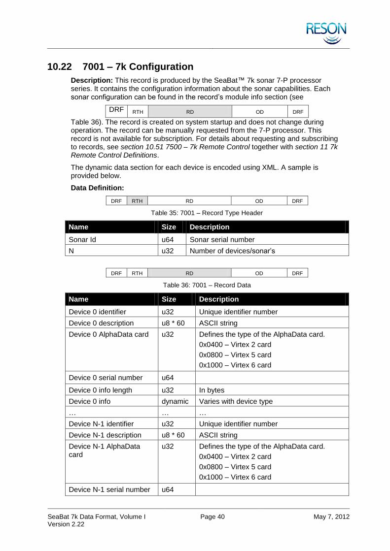
SeaBat 7k Data Format, Volume I Version 2.22
Page 40 May 7, 2012
10.22 7001 – 7k Configuration
Description: This record is produced by the SeaBat™ 7k sonar 7-P processor series. It contains the configuration information about the sonar capabilities. Each sonar configuration can be found in the record’s module info section (see
DRF RTH RD OD DRF
Table 36). The record is created on system startup and does not change during operation. The record can be manually requested from the 7-P processor. This record is not available for subscription. For details about requesting and subscribing to records, see section 10.51 7500 – 7k Remote Control together with section 11 7k Remote Control Definitions.
The dynamic data section for each device is encoded using XML. A sample is provided below.
Data Definition:
DRF RTH RD OD DRF
Table 35: 7001 – Record Type Header
Name Size Description
Sonar Id u64 Sonar serial number
N u32 Number of devices/sonar’s
DRF RTH RD OD DRF
Table 36: 7001 – Record Data
Name Size Description
Device 0 identifier u32 Unique identifier number
Device 0 description u8 * 60 ASCII string
Device 0 AlphaData card u32 Defines the type of the AlphaData card.
0x0400 – Virtex 2 card
0x0800 – Virtex 5 card
0x1000 – Virtex 6 card
Device 0 serial number u64
Device 0 info length u32 In bytes
Device 0 info dynamic Varies with device type
… … …
Device N-1 identifier u32 Unique identifier number
Device N-1 description u8 * 60 ASCII string
Device N-1 AlphaData card
u32 Defines the type of the AlphaData card.
0x0400 – Virtex 2 card
0x0800 – Virtex 5 card
0x1000 – Virtex 6 card
Device N-1 serial number u64

SeaBat 7k Data Format, Volume I Version 2.22
Page 41 May 7, 2012
Name Size Description
Device N-1 info length u32 In bytes
Device N-1 info dynamic Varies with device type
XML SAMPLE – 7125
<?xml version="1.0" encoding="US-ASCII"?>
<SB7125HF>
<Name deviceid="7125" enumerator="1" xml_reson="8.1.2.3.1.1">7125 (400kHz)</Name>
<SystemInfo auv="no" projectid="generic" systemrelease="SV3" name="7125">7125 Sonar</SystemInfo>
<SonarType type="0" unit="nb">Bathymetric sonar</SonarType>
<ArrayType type="1" number="7216" unit="nb">Flat array</ArrayType>
<RxElements min="0" max="255" spacing="0.0016" unit="meters" input_mux="1">Receive ceramics</RxElements>
<RxBeamWidth uniformacross="yes" uniformalong="yes" across="0.008" along="0.471238898" unit="rad">Receiver beamspacing</RxBeamWidth>
<RxBeamModeSet>
<RxBeamMode max_beams="240" beam_spacing="EA" min_coverage="45.0" max_coverage="140.0" min_grazing="15.0" max_total_steering="85.0">Minimum Beams</RxBeamMode>
<RxBeamMode max_beams="512" beam_spacing="ID" min_coverage="45.0" max_coverage="140.0" min_grazing="5.0" max_total_steering="85.0">Intermediate</RxBeamMode>
<RxBeamMode max_beams="512" beam_spacing="ED" min_coverage="45.0" max_coverage="140.0" min_grazing="15.0" max_total_steering="85.0">Best Coverage</RxBeamMode>
<RxBeamMode max_beams="512" beam_spacing="FL" min_coverage="45.0" max_coverage="140.0" min_grazing="15.0" max_total_steering="85.0">Flex</RxBeamMode>
<RxBeamMode max_beams="512" beam_spacing="EA" min_coverage="45.0" max_coverage="165.0" min_grazing="15.0" max_total_steering="85.0">Wide</RxBeamMode>
</RxBeamModeSet>
<RxBeamStabilization type="0">Receiver beam stabilization</RxBeamStabilization>
<TxType type="2181-400" number="2181" unit="nb">Standard</TxType>
<TxBeams min="0" max="0" unit="nb">Transmit beams</TxBeams>
<TxBeamSteering steerable="no" maxx="0.0" minx="0.0" maxz="0.0" minz="0.0" unit="rad">Transmit beam steering</TxBeamSteering>
<TxBeamSpacing uniform="yes" angles="0.0" unit="rad">Transmit beamspacing</TxBeamSpacing>
<TxBeamWidth variable="no" maxx="0.0174533" minx="0.0174533" maxz="2.094395102" minz="2.094395102" unit="rad">Transmit beamwidth</TxBeamWidth>
<TxBeamStabilization type="0">Transmit beam stabilization</TxBeamStabilization>
<TxPulseLength min="0.000030" max="0.000300" max_FM="0.020" unit="s" measured="1e-6">Transmit pulse length</TxPulseLength>
<TxPulseEnvelope type="tukey" parameter="0.1"> TxPulseEnvelope </TxPulseEnvelope>
<TxDelay trigger="999e-6" transmitter="999e-6" units="sec">Transmit Delay</TxDelay>
<Frequency chirp_V2="no" chirp_V6="yes" min="381000.0" max="411000.0" center="396000.0" unit="hz">Transmit frequency</Frequency>
<DualHead MasterStart="380000" MasterStop="400000" SlaveStart="420000" SlaveStop="400000" unit="Hz">Dual-Head FM frequencies</DualHead>

SeaBat 7k Data Format, Volume I Version 2.22
Page 42 May 7, 2012
<FM_Parameters KaiserLevel_dB="3" GuardBand_dB="3.0" CorrelationIndex="0.5" NegativeSweep="yes">FM Tuning Paramters</FM_Parameters>
<SampleRate rate="34482.75862" unit="hz">Receiver sample rate</SampleRate>
<Power min="190.0" max="220.0" tx_power_tweak="0.0" shared="no" unit="dB//uPa">Transmit power</Power>
<Gain min="0.0" max="83.0" tvg_limit="83" unit="dB">Receiver gain</Gain>
<Range min="5.0" max="400.0" unit="m">Operating range</Range>
<RangeSet size="20" _1="5" _2="8" _3="10" _4="15" _5="20" _6="25" _7="30" _8="35" _9="40" _10="50" _11="75" _12="100" _13="125" _14="150" _15="175" _16="200" _17="250" _18="300" _19="350" _20="400" unit="m">Valid Range Set</RangeSet>
<PingRate min="0.0" max="50.0" ratio="1.0" freerun="no" unit="p/s">Ping rate</PingRate>
<Motion rollable="yes" pitchable="no" heavable="no" roll="1" pitch="0" heave="0" roll_ON="yes" pitch_ON="yes">Motion compensation factor</Motion>
<FWInfo type="single" pps="new" bite="new" bf_upm_level="3">Firmware Info</FWInfo>
<FWFiles bitfile_V6="v6_256_20120422.bit" bitfile_V2="bf256_20110808.bit" BITEfile="7K_Bite_7125_SV2.xml">Firmware Sonar Specific Files</FWFiles>
<FWFilterFiles_V6 size="4" _1="0.0000999,filter1_v5_7125_7130_20110814.dat" _2="0.000199,filter2_v5_7125_7130_20110814.dat" _3="0.000299,filter3_v5_7125_7130_20110814.dat" _4="999,filter4_v5_7125_7130_20110814.dat">Firmware Filter Sonar Specific Files</FWFilterFiles_V6>
<FWFilterFiles_V2 size="4" _1="0.0000999,bf_filter1_7125_20110705.dat" _2="0.000199,bf_filter2_7125_20110705.dat" _3="0.000299,bf_filter3_7125_20110705.dat" _4="999,bf_filter4_7125_20110705.dat">Firmware Filter Sonar Specific Files</FWFilterFiles_V2>
<FPGA TxRxDelayOffset="0" tx_skip="0" rx_skip="0" lo_if="600000.0" delay="471e-6" offset_size="4" _1="4860" _2="4860" _3="4860" _4="4860">FPGA Sonar Specific Values</FPGA>
<DownLink register="yes" remote="yes">Downlink Commands</DownLink>
<RDR defaultpath="D:\Data\" maxsize="1024000000" units="Bytes" format="short" buffer="10">Raw data recording</RDR>
<StartState maxpower="0.0" ping="yes" selected="yes" udp="on" calibrate="yes" swiothrottlems="1000">Initial overwrite values</StartState>
<BottomDetection method="G2">BD Method (G1_Simple, G1_BlendFilt, G2)</BottomDetection>
<Warnings PPS="fatal" IOP="warning">Warning overrides</Warnings>
<GUIState wedgethrottlems="160">Initial overwrite values</GUIState>
<AutoPilot FactoryDefaultTable="7125_v6_400kHz_Default.apc">AutoPilot settings</AutoPilot>
<OutputBoost_dB Value="0">Beamformer Output Boost</OutputBoost_dB>
</SB7125HF>
10.23 7002 – 7k Match Filter
Description: This record is produced by the 7k Center. It contains the sonar’s receive match filter settings. The 7-P processor updates this data for each ping. The record can be manually requested for the last ping or subscribed to from the 7k Center. For details about requesting and subscribing to records, see section 10.51 7500 – 7k Remote Control together with section 11 7k Remote Control Definitions.

SeaBat 7k Data Format, Volume I Version 2.22
Page 43 May 7, 2012
Data Definition:
DRF RTH RD OD DRF
Table 37: 7002 – Record Type Header
Name Size Description
Sonar Id u64 Sonar serial number
Ping number u32 Sequential number
Operation u32 0 – Off
1 – On
Start frequency f32 Hz
Stop frequency f32 Hz
Window type u32 0 – Rectangular
1 – Kaiser
2 – Hamming
3 – Blackmann
4 – Triangular
5 – X (Taylor)
Shading value f32
Reserved u32 * 14
10.24 7003 – 7k Firmware and Hardware Configuration
Description: This record is produced by the 7k Center series. It contains the configuration information about the sonar hardware and firmware. The record is created on system startup and does not change during operation. The record can be manually requested from the 7k Center. This record is not available for subscription.
For details about requesting and subscribing to records, see section 10.51 7500 – 7k Remote Control together with section 11 7k Remote Control Definitions.
The dynamic data section is encoded using HTM. A sample is provided below.
Data Definition:
DRF RTH RD OD DRF
Table 38: 7003 – Record Type Header
Name Size Description
Devices u32 Hardware device count
Info length u32 Varies with device type

SeaBat 7k Data Format, Volume I Version 2.22
Page 44 May 7, 2012
HTM SAMPLE – 7101
HARDWARE TABLE
Name Hex Address Frequency Enumerator UI M2
SYS1 8101 Wet End 21 240000 N/A 8101 N/A
TX1 2A 240000 N/A 0 N/A
RX1 26 N/A N/A 0 N/A
LM 30 N/A N/A 7101 N/A
LM TABLE
Field Bytes Sensor Types
Name Min Max
1 2 0 Addresses Destination (MSB) Source (LSB)
0 0
2 2 0 Data Length 0 0
3 2 0 Type of Command 0 0
5 2 2 FPGA Die Temperature (°C) -5.0 95.0
8 2 4 5V 4.5 5.5
9 2 4 2.5Vref 2.4 2.6
10 2 4 1.5V 1.3 1.7
12 2 4 3.3V 3.0 3.6
13 2 4 2.5V 2.2 2.8
14 2 4 1.0V 0.9 1.1
23 2 5 Controller CPLD 0 0
24 2 5 Controller FPGA 0 0
25 2 5 Controller DSP Boot 0 0
26 2 5 Controller DSP System 0 0
32 2 1 LM Downlink 0 65535
33 2 1 FPGA Status Field 0 65535
35 2 1 LM Uplink (from LM) 0 65535
SYS1 TABLE
Field Bytes Sensor Types
Name Min Max
1 2 0 Addresses Destination (MSB) Source (LSB)
0 0
2 2 0 Data Length 0 0
3 2 0 Type of Command 0 0
4 4 6 Head temperature (°C) -20.0 70.0
5 4 7 Leak V 3.8 6.0
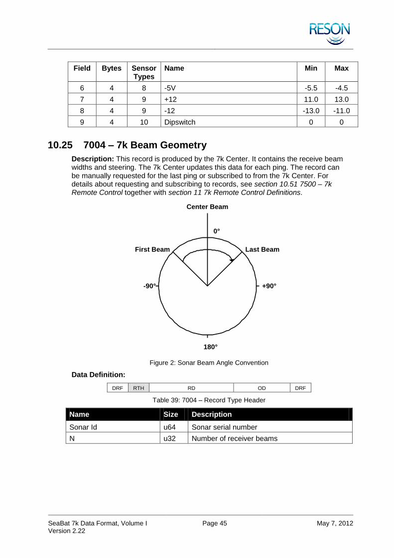
SeaBat 7k Data Format, Volume I Version 2.22
Page 45 May 7, 2012
Field Bytes Sensor Types
Name Min Max
6 4 8 -5V -5.5 -4.5
7 4 9 +12 11.0 13.0
8 4 9 -12 -13.0 -11.0
9 4 10 Dipswitch 0 0
10.25 7004 – 7k Beam Geometry
Description: This record is produced by the 7k Center. It contains the receive beam widths and steering. The 7k Center updates this data for each ping. The record can be manually requested for the last ping or subscribed to from the 7k Center. For details about requesting and subscribing to records, see section 10.51 7500 – 7k Remote Control together with section 11 7k Remote Control Definitions.
+90°
180°
0°
-90°
First Beam Last Beam
Center Beam
Figure 2: Sonar Beam Angle Convention
Data Definition:
DRF RTH RD OD DRF
Table 39: 7004 – Record Type Header
Name Size Description
Sonar Id u64 Sonar serial number
N u32 Number of receiver beams

SeaBat 7k Data Format, Volume I Version 2.22
Page 46 May 7, 2012
DRF RTH RD OD DRF
Table 40: 7004 – Record Data
Name Size Description
Beam vertical direction angle[N]
f32 * N Angle in radians. The receiver beam steering angle (relative to nadir) applied in the along-track direction (typically 0).
Beam horizontal direction angle[N]
f32 * N Angle in radians. The receiver beam steering angle (relative to nadir) applied in the across-track direction (varies according to beam number). Typically -75 to +75 degrees. In equi-distant mode, this will not change. In equi-angular mode, steering angles will vary.
-3dB Beam width Y[N] f32 * N Angle in radians. The receiver along-track beam width measured at the -3dB points (typically
<30).
-3dB Beam width X[N] f32 * N Angle in radians. The receiver across-track beam width measured at the -3dB points
(typically <5).
10.26 7006 – 7k Bathymetric Data
Description: This record is produced by the 7k Center series. It contains the sonar bottom detection results. The 7k Center updates this data for each ping. The record can be subscribed to from the 7k Center. For details about requesting and subscribing to records, see section 10.51 7500 – 7k Remote Control together with section 11 7k Remote Control Definitions.
Data Definition:
DRF RTH RD OD DRF
Table 41: 7006 – Record Type Header
Name Size Description
Sonar Id u64 Sonar serial number
Ping number u32 Sequential number
Multi-ping sequence u16 Flag to indicate multi-ping sequence. Always 0 (zero) if not in multi-ping mode; otherwise this represents the sequence number of the ping in the multi-ping sequence.
N u32 Number of receiver beams

SeaBat 7k Data Format, Volume I Version 2.22
Page 47 May 7, 2012
Name Size Description
Flags u8 BIT FIELD:
Bit 0: Layer compensation
0 – Off
1 – On
Bit 1: XYZ compensation
0 – Off
1 – On
Bit 2-7: Reserved (always 0)
Sound velocity flag u8 Flag indicating if sound velocity is measured or manually entered
0 – Measured
1 – Manually entered
Sound velocity f32 Sound velocity at the sonar in meters/second
DRF RTH RD OD DRF
Table 42: 7006 – Record Data
Name Size Description
Range [N] f32 * N Two-way travel time in seconds
Quality [N] u8 * N BIT FIELD:
Bit 0: Brightness
1 – Pass
0 – Fail
Bit 1:Colinearity
1 – Pass
0 – Fail
Bit 2: Bottom detection process (magnitude)
1 – Used
0 – Not used
Bit 3: Bottom detection process (phase):
1 – Used
0 – Not used
Bit 4: Used internally
Bit 5: PDS nadir filter
1 – Fail
0 – Pass
Bit 6-7: Reserved
Intensity [N] f32 * N Intensity: Signal strength. Value at bottom detection. Not calibrated.
Min filter info f32 * N Minimum two-way travel time to filter point for each beam (minimum depth gate)
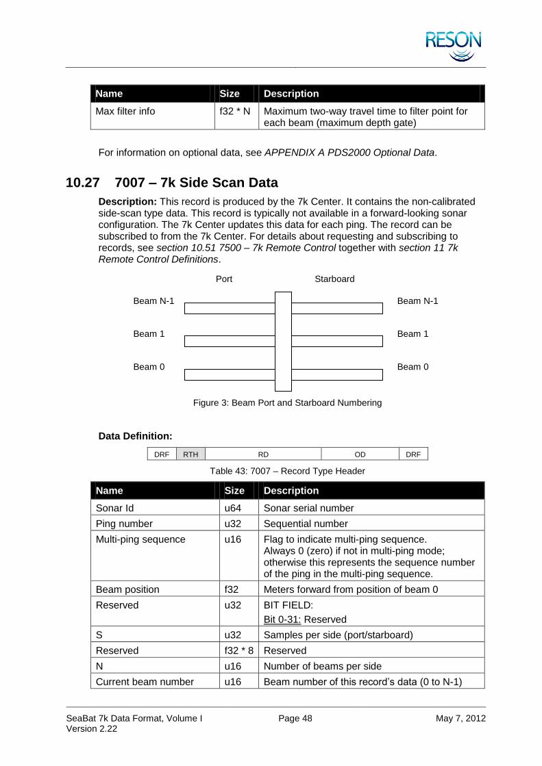
SeaBat 7k Data Format, Volume I Version 2.22
Page 48 May 7, 2012
Name Size Description
Max filter info f32 * N Maximum two-way travel time to filter point for each beam (maximum depth gate)
For information on optional data, see APPENDIX A PDS2000 Optional Data.
10.27 7007 – 7k Side Scan Data
Description: This record is produced by the 7k Center. It contains the non-calibrated side-scan type data. This record is typically not available in a forward-looking sonar configuration. The 7k Center updates this data for each ping. The record can be subscribed to from the 7k Center. For details about requesting and subscribing to records, see section 10.51 7500 – 7k Remote Control together with section 11 7k Remote Control Definitions.
Figure 3: Beam Port and Starboard Numbering
Data Definition:
DRF RTH RD OD DRF
Table 43: 7007 – Record Type Header
Name Size Description
Sonar Id u64 Sonar serial number
Ping number u32 Sequential number
Multi-ping sequence u16 Flag to indicate multi-ping sequence. Always 0 (zero) if not in multi-ping mode; otherwise this represents the sequence number of the ping in the multi-ping sequence.
Beam position f32 Meters forward from position of beam 0
Reserved u32 BIT FIELD:
Bit 0-31: Reserved
S u32 Samples per side (port/starboard)
Reserved f32 * 8 Reserved
N u16 Number of beams per side
Current beam number u16 Beam number of this record’s data (0 to N-1)
Port Starboard
Beam 0 Beam 0
Beam 1 Beam 1
Beam N-1 Beam N-1

SeaBat 7k Data Format, Volume I Version 2.22
Page 49 May 7, 2012
Name Size Description
W u8 Number of bytes per sample
Data types u8 BIT FIELD:
Bit 0: Reserved (always 0)
Bit 1-7: Reserved
DRF RTH RD OD DRF
Table 44: 7007 – Record Data
Name Size Description
Port beams W * S Magnitude/Phase series. First sample represents range 0 meters (total bytes per side).
Starboards beam W * S Magnitude/Phase series. First sample represents range 0 meters (total bytes per side).
For information on optional data, see APPENDIX A PDS2000 Optional Data.
10.28 7008 – 7k Generic Water Column Data
NOTE
Record 7008 is superseded by 7018 and 7028. It is mutually exclusive. The record is obsolete and will not be supported by Reson. It exists for the backwards compatibility only.
Description: This record is produced by the 7k Center. It contains the sonar beam “I” and “Q” or magnitude and phase data. The 7k Center transmits this data for each ping. This record is available by subscription only.
This record is used for snippet output as well. Beams and samples are numbered from 0. First beam to last beam fields are always enumerated from low to high numbers.
The Record Data portion is divided into two distinct parts:
Beam Descriptors
Sample Data
Beam Descriptors:
This part of the Record Data section contains each beam descriptor, followed by the beginning and ending sample numbers for that beam. For example:
b0 s1 s100 b2 s1 s100 b3 s1 s100 …
Where:
b = Beam
s = Sample
Sample Data
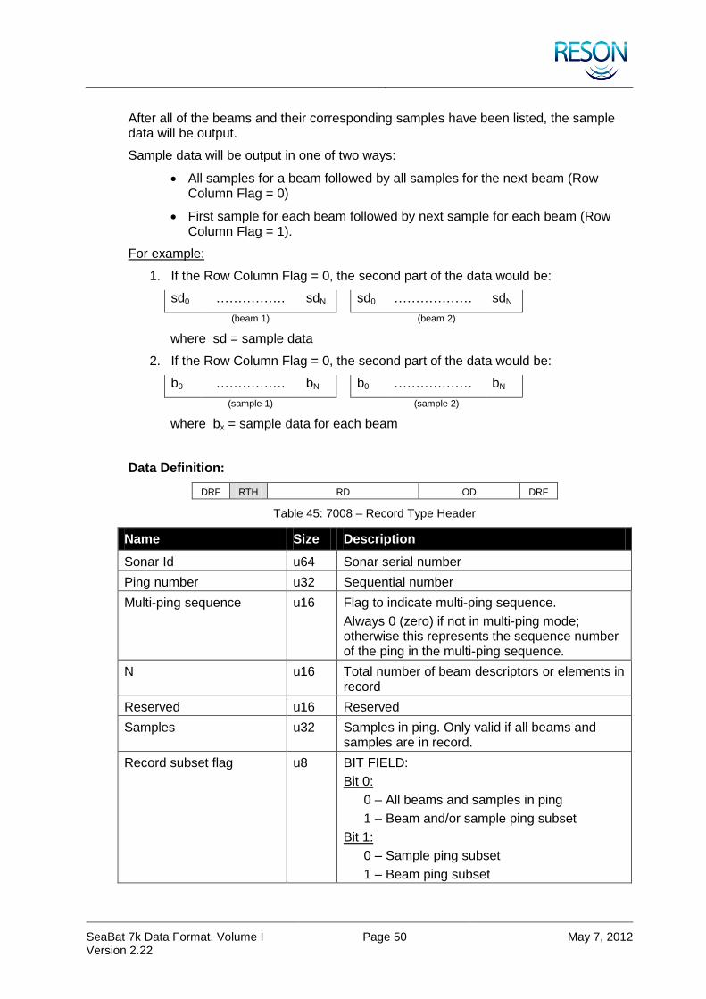
SeaBat 7k Data Format, Volume I Version 2.22
Page 50 May 7, 2012
After all of the beams and their corresponding samples have been listed, the sample data will be output.
Sample data will be output in one of two ways:
All samples for a beam followed by all samples for the next beam (Row Column Flag = 0)
First sample for each beam followed by next sample for each beam (Row Column Flag = 1).
For example:
1. If the Row Column Flag = 0, the second part of the data would be:
sd0 ……………. sdN sd0 ……………… sdN
(beam 1) (beam 2)
where sd = sample data
2. If the Row Column Flag = 0, the second part of the data would be:
b0 ……………. bN b0 ……………… bN
(sample 1) (sample 2)
where bx = sample data for each beam
Data Definition:
DRF RTH RD OD DRF
Table 45: 7008 – Record Type Header
Name Size Description
Sonar Id u64 Sonar serial number
Ping number u32 Sequential number
Multi-ping sequence u16 Flag to indicate multi-ping sequence.
Always 0 (zero) if not in multi-ping mode; otherwise this represents the sequence number of the ping in the multi-ping sequence.
N u16 Total number of beam descriptors or elements in record
Reserved u16 Reserved
Samples u32 Samples in ping. Only valid if all beams and samples are in record.
Record subset flag u8 BIT FIELD:
Bit 0:
0 – All beams and samples in ping
1 – Beam and/or sample ping subset
Bit 1:
0 – Sample ping subset
1 – Beam ping subset

SeaBat 7k Data Format, Volume I Version 2.22
Page 51 May 7, 2012
Name Size Description
Row column flag u8 0 – All samples for a beam, followed by all samples for the next beam
1 – Sample 1 for all beams, followed by Sample 2 for all beams, etc
Reserved u16 Reserved
Data sample type(s) u32 BIT FIELD:
(Least significant bit corresponds to Bit 0. Each grouping of bits is to be treated as an unsigned integer of the specified width. E.g., magnitude is an u4 with possible values in range 0 to 16.)
Bit 0-3: Magnitude
0 – No magnitude
1 – Reserved
2 – Magnitude (16 bits)
3 – Magnitude (32 bits)
Bit 4-7: Phase
0 – No phase
1 – Reserved
2 – Phase (16 bits)
3 – Phase (32 bits)
Bit 8-11: I and Q
0 – No I and Q
1 – Signed 16 bit I and signed 16 bit Q
2 – Signed 32 bit I and signed 32 bit Q
Bit 12-14: Beamforming flag
0 – Beam formed data
1 – Element data
DRF RTH RD OD DRF
Table 46: 7008 – Record Data (Part 1)
Name Size Description
Descriptor 0 u16 First beam or element number
First sample number u32 First sample number in beam from transmitter and outward
Last sample number u32 Last sample number in beam from transmitter and outward
… … …
Descriptor N-1 u16 Last beam or element number
First sample number u32 First sample number in beam from transmitter and outward

SeaBat 7k Data Format, Volume I Version 2.22
Page 52 May 7, 2012
Name Size Description
Last sample number u32 Last sample number in beam from transmitter and outward
Table 47: 7008 – Record Data (Part 2)
Name Size Description
First column/row dynamic First sample header + Magnitude/Phase series. Array is populated with samples from transmitter and outward, or beams from low beam number and increasing.
… … …
Last column/row dynamic Last Sample header + Magnitude/Phase series. Array is populated with samples from transmitter and outward, or beams from low beam number and increasing.
For information on optional data, see APPENDIX A PDS2000 Optional Data.
Additional SeaBat™ data settings (data reduction).
Beam limits, sample limits, and SeaBat™ format types can be combined.
Beams
Samples
Figure 4: Beam Limits – Set Min and Max Beam
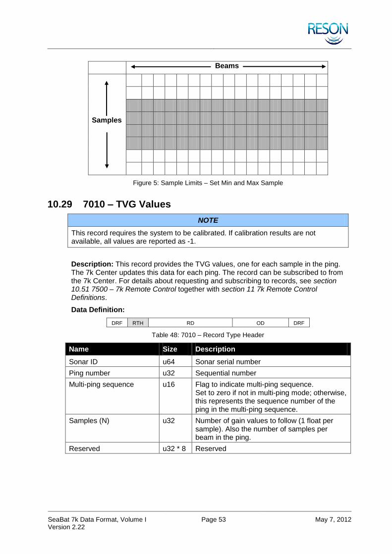
SeaBat 7k Data Format, Volume I Version 2.22
Page 53 May 7, 2012
Beams
Samples
Figure 5: Sample Limits – Set Min and Max Sample
10.29 7010 – TVG Values
NOTE
This record requires the system to be calibrated. If calibration results are not available, all values are reported as -1.
Description: This record provides the TVG values, one for each sample in the ping. The 7k Center updates this data for each ping. The record can be subscribed to from the 7k Center. For details about requesting and subscribing to records, see section 10.51 7500 – 7k Remote Control together with section 11 7k Remote Control Definitions.
Data Definition:
DRF RTH RD OD DRF
Table 48: 7010 – Record Type Header
Name Size Description
Sonar ID u64 Sonar serial number
Ping number u32 Sequential number
Multi-ping sequence u16 Flag to indicate multi-ping sequence. Set to zero if not in multi-ping mode; otherwise, this represents the sequence number of the ping in the multi-ping sequence.
Samples (N) u32 Number of gain values to follow (1 float per sample). Also the number of samples per beam in the ping.
Reserved u32 * 8 Reserved
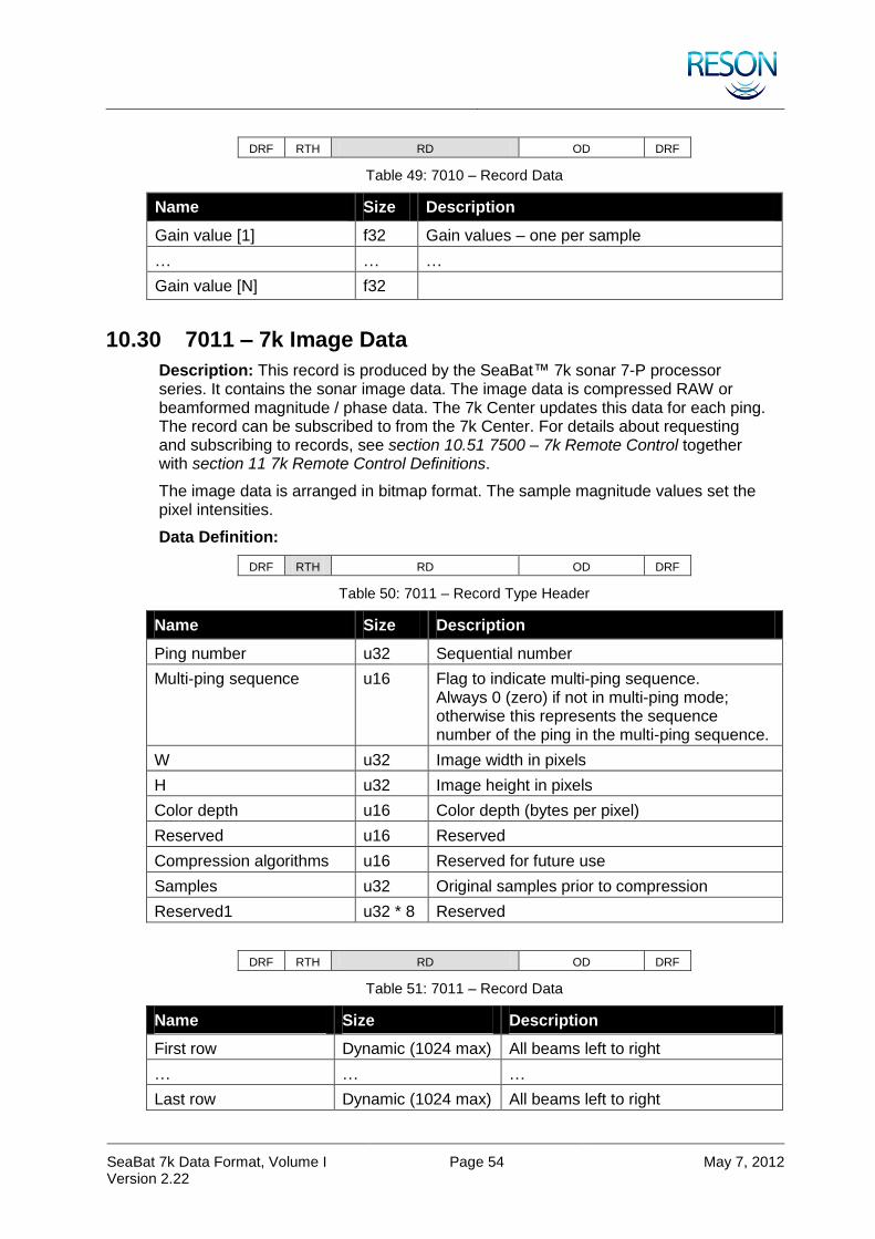
SeaBat 7k Data Format, Volume I Version 2.22
Page 54 May 7, 2012
DRF RTH RD OD DRF
Table 49: 7010 – Record Data
Name Size Description
Gain value [1] f32 Gain values – one per sample
… … …
Gain value [N] f32
10.30 7011 – 7k Image Data
Description: This record is produced by the SeaBat™ 7k sonar 7-P processor series. It contains the sonar image data. The image data is compressed RAW or beamformed magnitude / phase data. The 7k Center updates this data for each ping. The record can be subscribed to from the 7k Center. For details about requesting and subscribing to records, see section 10.51 7500 – 7k Remote Control together with section 11 7k Remote Control Definitions.
The image data is arranged in bitmap format. The sample magnitude values set the pixel intensities.
Data Definition:
DRF RTH RD OD DRF
Table 50: 7011 – Record Type Header
Name Size Description
Ping number u32 Sequential number
Multi-ping sequence u16 Flag to indicate multi-ping sequence. Always 0 (zero) if not in multi-ping mode; otherwise this represents the sequence number of the ping in the multi-ping sequence.
W u32 Image width in pixels
H u32 Image height in pixels
Color depth u16 Color depth (bytes per pixel)
Reserved u16 Reserved
Compression algorithms u16 Reserved for future use
Samples u32 Original samples prior to compression
Reserved1 u32 * 8 Reserved
DRF RTH RD OD DRF
Table 51: 7011 – Record Data
Name Size Description
First row Dynamic (1024 max) All beams left to right
… … …
Last row Dynamic (1024 max) All beams left to right
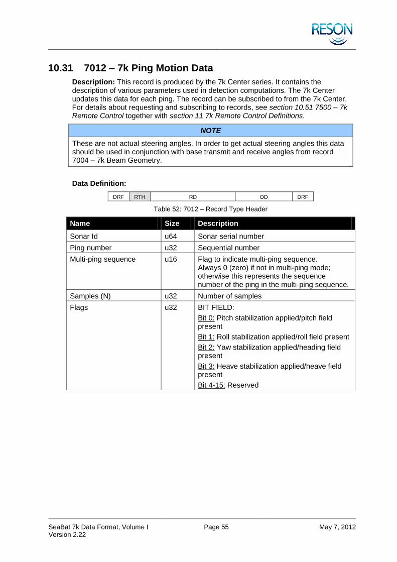
SeaBat 7k Data Format, Volume I Version 2.22
Page 55 May 7, 2012
10.31 7012 – 7k Ping Motion Data
Description: This record is produced by the 7k Center series. It contains the description of various parameters used in detection computations. The 7k Center updates this data for each ping. The record can be subscribed to from the 7k Center. For details about requesting and subscribing to records, see section 10.51 7500 – 7k Remote Control together with section 11 7k Remote Control Definitions.
NOTE
These are not actual steering angles. In order to get actual steering angles this data should be used in conjunction with base transmit and receive angles from record 7004 – 7k Beam Geometry.
Data Definition:
DRF RTH RD OD DRF
Table 52: 7012 – Record Type Header
Name Size Description
Sonar Id u64 Sonar serial number
Ping number u32 Sequential number
Multi-ping sequence u16 Flag to indicate multi-ping sequence. Always 0 (zero) if not in multi-ping mode; otherwise this represents the sequence number of the ping in the multi-ping sequence.
Samples (N) u32 Number of samples
Flags u32 BIT FIELD:
Bit 0: Pitch stabilization applied/pitch field present
Bit 1: Roll stabilization applied/roll field present
Bit 2: Yaw stabilization applied/heading field present
Bit 3: Heave stabilization applied/heave field present
Bit 4-15: Reserved

SeaBat 7k Data Format, Volume I Version 2.22
Page 56 May 7, 2012
Name Size Description
Error flags u32 BIT FIELD:
Bit 0: PHINS reference
0 – Valid
1 – Invalid
Bit 1-3: Reserved for PHINS
Bit 4: Roll angle >15 degrees
Bit 5: Roll angle >35 degrees
Bit 6: Roll rate > 10 degrees
Bit 7:
1 – External motion data not received (roll angle and rate are not reported)
Bit 8-15: Reserved
Sampling rate f32 Sampling frequency in Hz
Pitch f32 Pitch value at the ping time in radians
Roll f32 * N Roll value per sample in radians
Heading f32 * N Heading value per sample in radians
Heave f32 * N Heave value per sample in meters
NOTE
The fields, Pitch, Roll, Heading, and Heave, are present only if corresponding flags are set. The new fields may be added (refer to the record size in the record header for the total size). For sign explanations, see section 2.2 Sign Conventions.
10.32 7017 – 7k Detection Data Setup
Description: This record is produced by the 7k Center series. It contains the description of various parameters used in detection computations. The 7k Center updates this data for each ping. The record can be subscribed to from the 7k Center. For details about requesting and subscribing to records, see section 10.51 7500 – 7k Remote Control together with section 11 7k Remote Control Definitions. This record is available by subscription only.
Data Definition:
DRF RTH RD OD DRF
Table 53: 7017 – Record Type Header
Name Size Description
Sonar Id u64 Sonar serial number
Ping number u32 Sequential number
Multi-ping sequence u16 Flag to indicate multi-ping sequence. Always 0 (zero) if not in multi-ping mode; otherwise this represents the sequence number of the ping in the multi-ping sequence.

SeaBat 7k Data Format, Volume I Version 2.22
Page 57 May 7, 2012
Name Size Description
N u32 Number of detection points
Data block size (S) u32 Size of detection information block in bytes
Detection algorithm u8 0 – G1_Simple
1 – G1_BlendFilt
2 – G2
3 – G3
4 – IF1
5-255 – Reserved for future use
Flags u32 BIT FIELD:
Bit 0:
1 – User-defined depth filter enabled
Bit 1:
1 – User-defined range filter enabled
Bit 2:
1 – Automatic filter enabled
Bit 3:
1 – Nadir search limits enabled
Bit 4:
1 – Automatic window limits enabled
Bit 5:
1 – Quality filter is applied; only detections that pass the filter are outputted
Bit 6-31: Reserved for future use
Minimum depth f32 Minimum depth for user-defined filter in meters
Maximum depth f32 Maximum depth for user-defined filter in meters
Minimum range f32 Minimum range for user-defined filter in meters
Maximum range f32 Maximum range for user-defined filter in meters
Minimum nadir search f32 Minimum depth for automatic filter nadir search in meters
Maximum nadir search f32 Maximum depth for automatic filter nadir search in meters
Automatic filter window u8 Automatic filter window size in percent of the depth
Applied roll f32 Roll value (in radians) applied to gates; zero if roll stabilization is ON
Depth gate tilt f32 Angle in radians (positive to starboard)
Reserved u32 * 14 Reserved for future use

SeaBat 7k Data Format, Volume I Version 2.22
Page 58 May 7, 2012
NOTE
The following data section is repeated for each detection point as defined in RTH. The size of each field is always defined in RTH (S). If the size of this definition does not match the size specified in the record’s header, the user must assume that there is an updated revision of this record and that new fields are added at the end.
DRF RTH RD OD DRF
Table 54: 7017 – Record Data
Name Size Description
Beam descriptor u16 Beam number the detection is taken from
Detection point f32 Beam steering angle with reference to receiver’s acoustic center in the sonar reference frame, at the detection point; in radians
Flags u32 BIT FIELD:
Bit 0:
1 – Automatic limits valid
Bit 1:
1 – User-defined limits valid
Bit 2-8: Quality type, defines the type of the quality field
Bit 9:
1 – Quality passes user-defined criteria or no user-defined criteria was specified
Bit 10:
1 – Magnitude based detection
Bit 11:
1 – Phase based detection
Bit 12:
1 – Other detection 1
Note that bits 1-13 are not mutually exclusive. For example, bits 10 & 11 will both be set when the current ‘blend’ of magnitude and phase detection is used.
Bit 13-31: Reserved for future use
Automatic limits minimum sample
f32 Minimum sample number for automatic limits
Automatic limits maximum sample
f32 Maximum sample number for automatic limits
User-defined limits minimum sample
f32 Minimum sample number for user-defined limits
User-defined limits maximum sample
f32 Maximum sample number for user-defined limits

SeaBat 7k Data Format, Volume I Version 2.22
Page 59 May 7, 2012
Name Size Description
Quality 32 bits Detection quality, see Table 55
Uncertainty f32 Detection uncertainty represented as an error normalized to the detection point
The quality field above should be treated as follows, according to the quality type specified in the record data’s flags (bits 2-8):
Table 55: 7017 – Detection Quality
Name Size Description
0 u32 Quality is not available/not used
1 u32 BIT FIELD:
Bit 0:
1 – Brightness filter passed
Bit 1:
1 – Colinearity filter passed
2-31 Reserved for future use
10.33 7018 – 7k Beamformed Data
Description: This record is produced by the 7k Center series. It contains the sonar beam magnitude and phase data. The 7k Center updates this data for each ping. The record can be subscribed to from the 7k Center. For details about requesting and subscribing to records, see section 10.51 7500 – 7k Remote Control together with section 11 7k Remote Control Definitions. This record is available by subscription only.
For details about subscribing to records, see section 10.51 7500 – 7k Remote Control together with section 11 7k Remote Control Definitions.
Beams and samples are numbered from 0. Data is sample followed by beams.
Data rates:
Equation for no data reduction, beam limits, and all sonar settings:
beams * data format bits * sample rate * 10% (header overhead)
Example:
128 beams * 32 bits (sonar setting 6) * 34500 samples/s * 1.1 = 155.4432 Mbits/s
Data Definition:
DRF RTH RD OD DRF
Table 56: 7018 – Record Type Header
Name Size Description
Sonar Id u64 Sonar serial number
Ping number u32 Sequential number

SeaBat 7k Data Format, Volume I Version 2.22
Page 60 May 7, 2012
Name Size Description
Multi-ping sequence u16 Flag to indicate multi-ping sequence. Always 0 (zero) if not in multi-ping mode; otherwise this represents the sequence number of the ping in the multi-ping sequence.
Beams (N) u16 Total number of beams in ping record
Samples (S) u32 Total number of samples in ping record
Reserved u32 * 8 Reserved for future use
DRF RTH RD OD DRF
Table 57: 7018 – Record Data
Name Size Description
Sample 0, Beam 0, Amp u16 Amplitude value for first sample, first beam (First sample represents range 0 meters)
Sample 0, Beam 0, Phs i16 Phase value for first sample, first beam (First sample represents range 0 meters) (Phase values are in radians scaled by 10430)
… … …
Sample 0, Beam N-1, Amp u16 Amplitude value for first sample, last beam
Sample 0, Beam N-1, Phs i16 Phase value for first sample, last beam
… … …
Sample S-1, Beam N-1, Amp u16 Amplitude value for last sample, last beam
Sample S-1, Beam N-1, Phs i16 Phase value for last sample, last beam
10.34 7021 – 7k Built-In Test Environment Data
Description: This record is produced by the SeaBat™ 7k Sonar 7-P processor. It contains both the Built-In Test Environment (BITE) data and board request data (uplink/downlink). The 7k Center updates this record when any of the values have changed and publishes it every second. The record can be manually requested or subscribed to from the 7k Center.
For details about requesting and subscribing to records, see section 10.51 7500 – 7k Remote Control together with section 11 7k Remote Control Definitions.
Data Definition:
DRF RTH RD OD DRF
Table 58: 7021 – Record Type Header
Name Size Description
N u16 Number of boards reporting
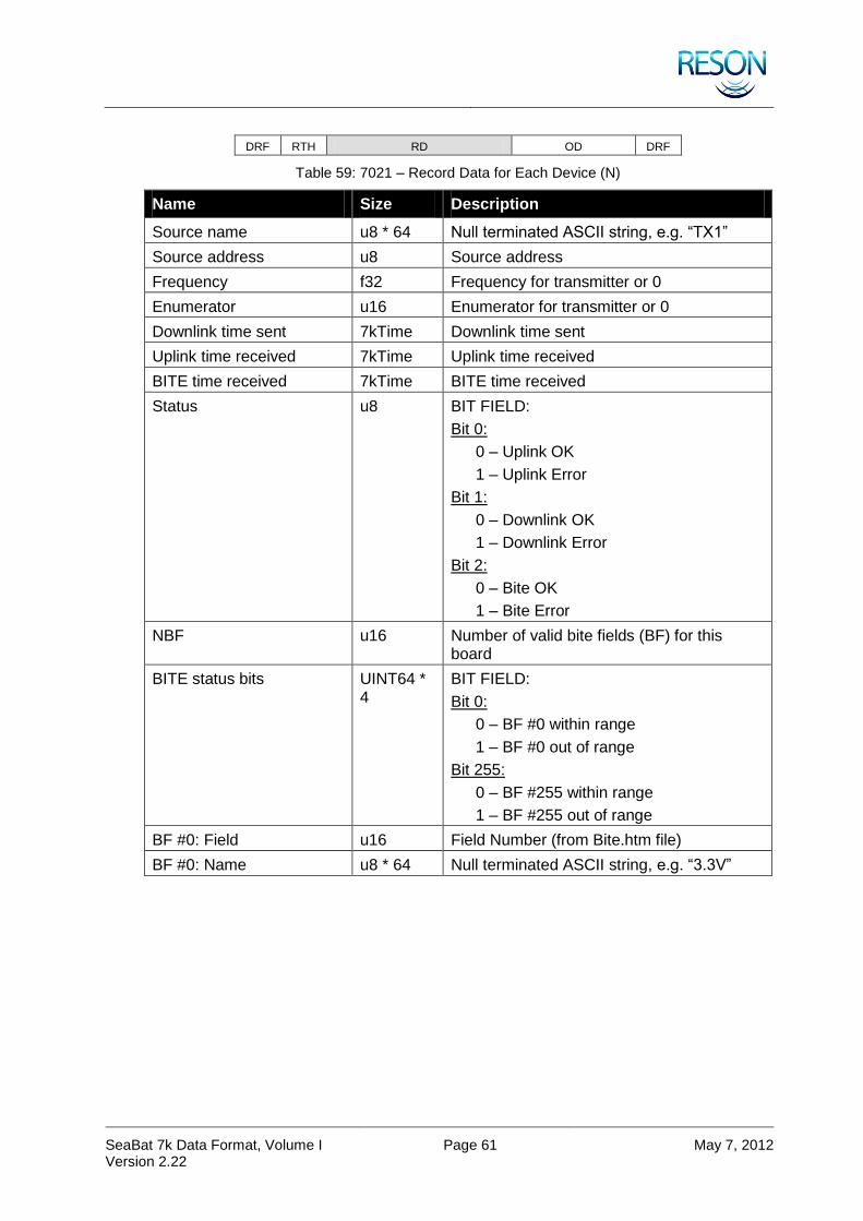
SeaBat 7k Data Format, Volume I Version 2.22
Page 61 May 7, 2012
DRF RTH RD OD DRF
Table 59: 7021 – Record Data for Each Device (N)
Name Size Description
Source name u8 * 64 Null terminated ASCII string, e.g. “TX1”
Source address u8 Source address
Frequency f32 Frequency for transmitter or 0
Enumerator u16 Enumerator for transmitter or 0
Downlink time sent 7kTime Downlink time sent
Uplink time received 7kTime Uplink time received
BITE time received 7kTime BITE time received
Status u8 BIT FIELD:
Bit 0:
0 – Uplink OK
1 – Uplink Error
Bit 1:
0 – Downlink OK
1 – Downlink Error
Bit 2:
0 – Bite OK
1 – Bite Error
NBF u16 Number of valid bite fields (BF) for this board
BITE status bits UINT64 * 4
BIT FIELD:
Bit 0:
0 – BF #0 within range
1 – BF #0 out of range
Bit 255:
0 – BF #255 within range
1 – BF #255 out of range
BF #0: Field u16 Field Number (from Bite.htm file)
BF #0: Name u8 * 64 Null terminated ASCII string, e.g. “3.3V”
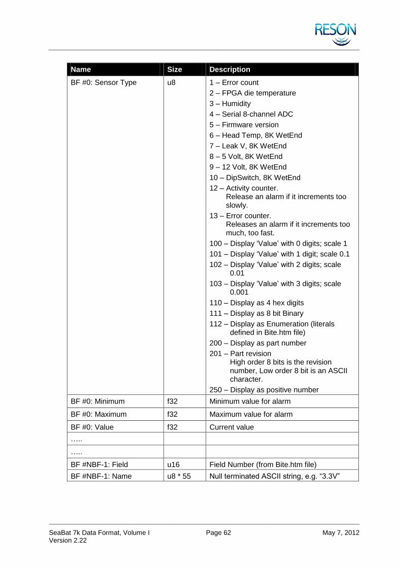
SeaBat 7k Data Format, Volume I Version 2.22
Page 62 May 7, 2012
Name Size Description
BF #0: Sensor Type u8 1 – Error count
2 – FPGA die temperature
3 – Humidity
4 – Serial 8-channel ADC
5 – Firmware version
6 – Head Temp, 8K WetEnd
7 – Leak V, 8K WetEnd
8 – 5 Volt, 8K WetEnd
9 – 12 Volt, 8K WetEnd
10 – DipSwitch, 8K WetEnd
12 – Activity counter. Release an alarm if it increments too slowly.
13 – Error counter. Releases an alarm if it increments too much, too fast.
100 – Display ‘Value’ with 0 digits; scale 1
101 – Display ‘Value’ with 1 digit; scale 0.1
102 – Display ‘Value’ with 2 digits; scale 0.01
103 – Display ‘Value’ with 3 digits; scale 0.001
110 – Display as 4 hex digits
111 – Display as 8 bit Binary
112 – Display as Enumeration (literals defined in Bite.htm file)
200 – Display as part number
201 – Part revision High order 8 bits is the revision number, Low order 8 bit is an ASCII character.
250 – Display as positive number
BF #0: Minimum f32 Minimum value for alarm
BF #0: Maximum f32 Maximum value for alarm
BF #0: Value f32 Current value
…..
…..
BF #NBF-1: Field u16 Field Number (from Bite.htm file)
BF #NBF-1: Name u8 * 55 Null terminated ASCII string, e.g. “3.3V”
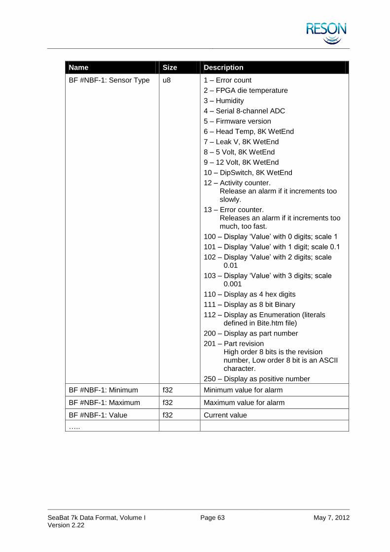
SeaBat 7k Data Format, Volume I Version 2.22
Page 63 May 7, 2012
Name Size Description
BF #NBF-1: Sensor Type u8 1 – Error count
2 – FPGA die temperature
3 – Humidity
4 – Serial 8-channel ADC
5 – Firmware version
6 – Head Temp, 8K WetEnd
7 – Leak V, 8K WetEnd
8 – 5 Volt, 8K WetEnd
9 – 12 Volt, 8K WetEnd
10 – DipSwitch, 8K WetEnd
12 – Activity counter. Release an alarm if it increments too slowly.
13 – Error counter. Releases an alarm if it increments too much, too fast.
100 – Display ‘Value’ with 0 digits; scale 1
101 – Display ‘Value’ with 1 digit; scale 0.1
102 – Display ‘Value’ with 2 digits; scale 0.01
103 – Display ‘Value’ with 3 digits; scale 0.001
110 – Display as 4 hex digits
111 – Display as 8 bit Binary
112 – Display as Enumeration (literals defined in Bite.htm file)
200 – Display as part number
201 – Part revision High order 8 bits is the revision number, Low order 8 bit is an ASCII character.
250 – Display as positive number
BF #NBF-1: Minimum f32 Minimum value for alarm
BF #NBF-1: Maximum f32 Maximum value for alarm
BF #NBF-1: Value f32 Current value
…..
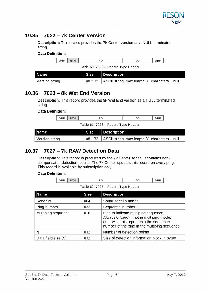
SeaBat 7k Data Format, Volume I Version 2.22
Page 64 May 7, 2012
10.35 7022 – 7k Center Version
Description: This record provides the 7k Center version as a NULL terminated string.
Data Definition:
DRF RTH RD OD DRF
Table 60: 7022 – Record Type Header
Name Size Description
Version string u8 * 32 ASCII string, max length 31 characters + null
10.36 7023 – 8k Wet End Version
Description: This record provides the 8k Wet End version as a NULL terminated string.
Data Definition:
DRF RTH RD OD DRF
Table 61: 7023 – Record Type Header
Name Size Description
Version string u8 * 32 ASCII string, max length 31 characters + null
10.37 7027 – 7k RAW Detection Data
Description: This record is produced by the 7k Center series. It contains non-compensated detection results. The 7k Center updates this record on every ping. This record is available by subscription only.
Data Definition:
DRF RTH RD OD DRF
Table 62: 7027 – Record Type Header
Name Size Description
Sonar Id u64 Sonar serial number
Ping number u32 Sequential number
Multiping sequence u16 Flag to indicate multiping sequence. Always 0 (zero) if not in multiping mode; otherwise this represents the sequence number of the ping in the multiping sequence.
N u32 Number of detection points
Data field size (S) u32 Size of detection information block in bytes
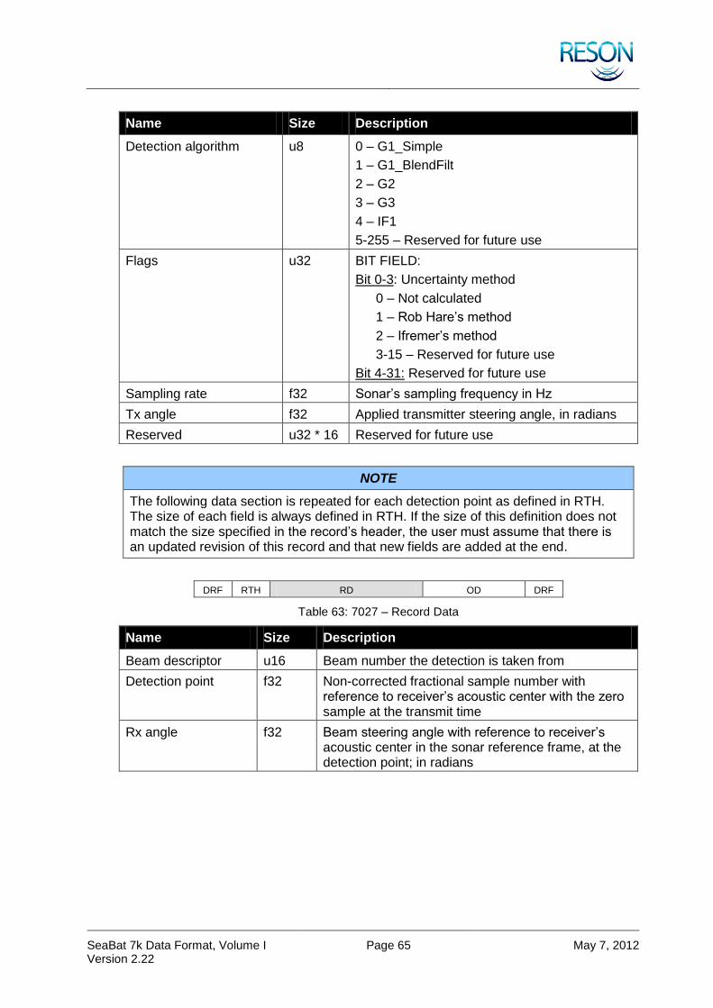
SeaBat 7k Data Format, Volume I Version 2.22
Page 65 May 7, 2012
Name Size Description
Detection algorithm u8 0 – G1_Simple
1 – G1_BlendFilt
2 – G2
3 – G3
4 – IF1
5-255 – Reserved for future use
Flags u32 BIT FIELD:
Bit 0-3: Uncertainty method
0 – Not calculated
1 – Rob Hare’s method
2 – Ifremer’s method
3-15 – Reserved for future use
Bit 4-31: Reserved for future use
Sampling rate f32 Sonar’s sampling frequency in Hz
Tx angle f32 Applied transmitter steering angle, in radians
Reserved u32 * 16 Reserved for future use
NOTE
The following data section is repeated for each detection point as defined in RTH. The size of each field is always defined in RTH. If the size of this definition does not match the size specified in the record’s header, the user must assume that there is an updated revision of this record and that new fields are added at the end.
DRF RTH RD OD DRF
Table 63: 7027 – Record Data
Name Size Description
Beam descriptor u16 Beam number the detection is taken from
Detection point f32 Non-corrected fractional sample number with reference to receiver’s acoustic center with the zero sample at the transmit time
Rx angle f32 Beam steering angle with reference to receiver’s acoustic center in the sonar reference frame, at the detection point; in radians
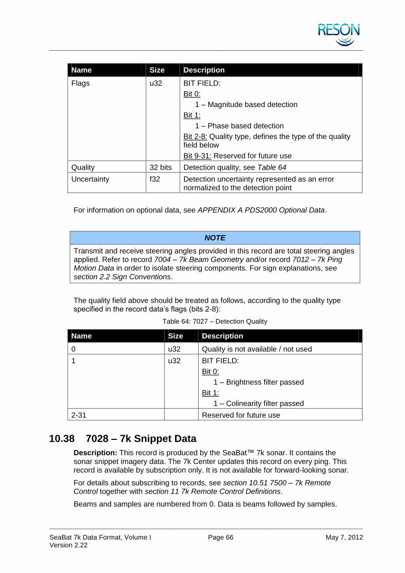
SeaBat 7k Data Format, Volume I Version 2.22
Page 66 May 7, 2012
Name Size Description
Flags u32 BIT FIELD:
Bit 0:
1 – Magnitude based detection
Bit 1:
1 – Phase based detection
Bit 2-8: Quality type, defines the type of the quality field below
Bit 9-31: Reserved for future use
Quality 32 bits Detection quality, see Table 64
Uncertainty f32 Detection uncertainty represented as an error normalized to the detection point
For information on optional data, see APPENDIX A PDS2000 Optional Data.
NOTE
Transmit and receive steering angles provided in this record are total steering angles applied. Refer to record 7004 – 7k Beam Geometry and/or record 7012 – 7k Ping Motion Data in order to isolate steering components. For sign explanations, see section 2.2 Sign Conventions.
The quality field above should be treated as follows, according to the quality type specified in the record data’s flags (bits 2-8):
Table 64: 7027 – Detection Quality
Name Size Description
0 u32 Quality is not available / not used
1 u32 BIT FIELD:
Bit 0:
1 – Brightness filter passed
Bit 1:
1 – Colinearity filter passed
2-31 Reserved for future use
10.38 7028 – 7k Snippet Data
Description: This record is produced by the SeaBat™ 7k sonar. It contains the sonar snippet imagery data. The 7k Center updates this record on every ping. This record is available by subscription only. It is not available for forward-looking sonar.
For details about subscribing to records, see section 10.51 7500 – 7k Remote Control together with section 11 7k Remote Control Definitions.
Beams and samples are numbered from 0. Data is beams followed by samples.

SeaBat 7k Data Format, Volume I Version 2.22
Page 67 May 7, 2012
Beams
Samples
Figure 6: Sample Limits – Set Min and Max Sample
Data rates:
Equation for no data reduction, beam limits, and all sonar settings:
beams * data format bits * sample rate * 10% (header overhead)
Example:
128 beams * 32 bits (sonar setting 5) * 34500 samples/s * 1.1 = 155.4432 Mbits/s
Equation for sample limits:
beams * ping rate * samples * data format bits * 10%
Example:
128 beams * 7 ping/s * 3000 samples * 8 bits (sonar setting 1) * 1.1 = 23.6544 Mbits/s
Data Definition:
DRF RTH RD OD DRF
Table 65: 7028 – Record Type Header
Name Size Description
Sonar Id u64 Sonar serial number
Ping number u32 Sequential number
Multi-ping sequence u16 Flag to indicate multi-ping sequence. Always 0 (zero) if not in multi-ping mode; otherwise this represents the sequence number of the ping in the multi-ping sequence.
N u16 Number of detection points

SeaBat 7k Data Format, Volume I Version 2.22
Page 68 May 7, 2012
Name Size Description
Error flag u8 If set, record will not contain any data. Flag itself will indicate an error.
0 – OK
1-5 – Reserved
6 – Bottom detection failed (R7006)
7-255 – Reserved
Control flags u8 Control settings from RC 1118
0 – Automatic snippet window is used
1 – Quality Filter enabled
2 – Minimum window size is required
3 – Maximum window size is required
4-7 – Reserved
Reserved u32 * 7 Reserved for future use
DRF RTH RD OD DRF
Table 66: 7028 – Record Data
Name Size Description
Beam descriptor[1] u16 Beam number
Snippet start[1] u32 First sample included in the snippet
Detection sample[1] u32 Detection point
Snippet End[1] u32 Last sample included in the snippet
… … …
Beam descriptor[N] u16 Beam number
Snippet start[N] u32 First sample included in the snippet
Detection sample[N] u32 Detection point
Snippet end[N] u32 Last sample included in the snippet
First snippet Dynamic, u16 Amplitude series for each sample. Array is populated with samples from the first sample to the last as defined above.
… … …
Last beam Dynamic, u16 Amplitude series for each sample. Array is populated with samples from the first sample to the last as defined above.
For information on optional data, see APPENDIX A PDS2000 Optional Data.
10.39 7041 – Compressed Beamformed Magnitude Data
Description: This record is produced by the SeaBat™ 7k sonar 7-P processor series. It contains the compressed magnitude sonar beam data. The 7-P processor

SeaBat 7k Data Format, Volume I Version 2.22
Page 69 May 7, 2012
updates this record for each ping. The record can be subscribed to from the 7-P processor; it is not available by single request. For details about requesting and subscribing to records, see section 10.51 7500 – 7k Remote Control together with section 11 7k Remote Control Definitions.
Data Definition:
DRF RTH RD OD DRF
Table 67: 7041 – Record Type Header
Name Size Description
Sonar Id u64 Sonar serial number
Ping number u32 Sequential number
Multi-ping sequence u16 Flag to indicate multi-ping sequence. Always 0 (zero) if not in multi-ping mode; otherwise this represents the sequence number of the ping in the multi-ping sequence.
Number of Beams (B) u16 Total number of beams in ping record
Down-sampling Method u8 0 – No down-sampling
1 – Nearest neighbor
2 – Linear approximation
3 – Averaging
4+ – Reserved for future use
Filtering Method u8 0 – No filtering
1+ – Reserved for future use
Flags u32 BIT FIELD:
Bit 0-3: Data Encoding
0 – 16bit magnitude
1 – 8bit magnitude
2 – 16bit magnitude & phase
3 – 8bit magnitude & phase
4 – 32bit calibrated magnitude
5 – 16bit calibrated magnitude
6 – 8bit calibrated magnitude
7 – Reserved
Bit 4: Beam identification method
0 – Beam number (u16)
1 – Beam angle (f32, in radians)
Bit 5-31: Reserved (always zero)

SeaBat 7k Data Format, Volume I Version 2.22
Page 70 May 7, 2012
Name Size Description
Magnitude/Calibrated Magnitude Encoding
u8 Magnitude Encoding Methods:
0 – 16 bit values
1 – 8 bit ½dB
2+ – Reserved
Calibrated Magnitude Encoding Methods:
0+ – Reserved
Phase Encoding u8 Phase Encoding Methods:
0+ – Reserved
Sample Rate f32 Sampling rate for the data
Reserved 4*u32 Reserved for future use
DRF RTH RD OD DRF
Table 68: 7041 – Record Data for Each Beam (B)
Name Size Description
Beam var Identification for the beam. (See “Beam identification method” above)
Number of Samples (S) u32 Total number of samples recorded for this beam
Data S*var Data series for each sample. Either Magnitude, Magnitude and Phase pairs or Calibrated Magnitude. See “Flags” above for identification and size.
10.40 7048 – 7k Calibrated Beam Data
NOTE
This record contains non-calibrated beam magnitude, if calibration is available but not run. (See Error flag in Table 69: 7048 – Record Type Header).
Description: This record is produced by the SeaBat™ 7k sonar series. It contains the calibrated sonar beam magnitude. The 7k Center updates this record for each ping.
Beams and samples are numbered from 0. Data is sample followed by beams.
Additional SeaBat™ Data Settings (Data Reduction).
Both beam limits and SeaBat™ format types can be combined.

SeaBat 7k Data Format, Volume I Version 2.22
Page 71 May 7, 2012
Beams
Samples
Figure 7: Beam Limits – Set Min and Max Beam
Data Definition:
DRF RTH RD OD DRF
Table 69: 7048 – Record Type Header
Name Size Description
Sonar Id u64 Sonar serial number
Ping number u32 Sequential number
Multi-ping sequence u16 Flag to indicate multi-ping sequence. Always 0 (zero) if not in multi-ping mode; otherwise this represents the sequence number of the ping in the multi-ping sequence
First beam u16 Beam reduction initial beam
N u16 Total number of beams in ping record
S u32 Total number of samples in ping record
Forward-looking sonar u8 FLS flag
Error flag u8 If set, record contains original non-calibrated beamformed data. Flag itself will indicate an error.
0 – OK
1 – No calibration
2 – TVG read error (R7010)
3 – CTD not available (R1010)
4 – Invalid or not available geometry (R7004)
5 – Invalid sonar specifications (XML)
6 – Bottom detection failed
7 – No power (Power is set to zero)
8 – No gain (Gain is too low)
128-254 – Reserved for internal errors
255 – System cannot be calibrated (c7k file missing)

SeaBat 7k Data Format, Volume I Version 2.22
Page 72 May 7, 2012
Name Size Description
Reserved u32 * 8 Reserved for future use
DRF RTH RD OD DRF
Table 70: 7048 – Record Data
Name Size Description
First sample N * f32 Amplitude series for each beam. First sample represents range 0 meters.
… … …
Last sample (S) N * f32 Amplitude series for each beam
10.41 7050 – 7k System Events
Description: This record is produced by the SeaBat™ 7k sonar series. It contains the 7k Center system events. The 7k Center updates this record when any event is added or removed in the system. The record can be manually requested or subscribed to from the 7k Center. For details about requesting and subscribing to records, see section 10.51 7500 – 7k Remote Control together with section 11 7k Remote Control Definitions.
Data Definition:
DRF RTH RD OD DRF
Table 71: 7050 – Record Type Header
Name Size Description
Sonar Id u64 Sonar serial number
N u32 Number of events
DRF RTH RD OD DRF
Table 72: 7050 – Record Data
Name Size Description
Event type 0 u16 0 – Success
1 – Information
2 – Warning
3 – Error
Event identifier u16 0 – Not defined
Device identifier u32 Identifier of the device that this data pertains (or 7000 for system event)
System enumerator u16 System enumerator for identical systems in one installation
Event message length (L) u16 Message length including termination character

SeaBat 7k Data Format, Volume I Version 2.22
Page 73 May 7, 2012
Name Size Description
7KTIME u8 * 10 Time tag
Event message u8 * L Fixed-width string
… … …
Event type N-1 u16 0 – Success
1 – Information
2 – Warning
3 – Error
Event identifier u16 0 – Not defined
Device identifier u32 Identifier of the device that this data pertains
System enumerator u16 System enumerator for identical systems in one installation
Event message length (L) u16 Message length including termination character
7KTIME u8 * 10 Time tag
Event message u8 * L Fixed-width string
10.42 7051 – 7k System Event Message
Description: This record is produced by the SeaBat™ 7k sonar series. It holds a single 7k event. The latest record can be manually requested or subscribed to from the 7k Center. For details about requesting and subscribing to records, see section 10.51 7500 – 7k Remote Control together with section 11 7k Remote Control Definitions.
Data Definition:
DRF RTH RD OD DRF
Table 73: 7051 – Record Type Header
Name Size Description
Sonar Id u64 Sonar serial number
Event Id u16 0 – Success
1 – Information
2 – Warning
3 – Error
Message length u16 Message length in bytes
Event identifier u16 0 – Undefined
DRF RTH RD OD DRF
Table 74: 7051 – Record Data
Name Size Description
Event message dynamic Null terminated string.

SeaBat 7k Data Format, Volume I Version 2.22
Page 74 May 7, 2012
10.43 7052 – RDR Recording Status
Description: This record is generated at every 1% drop in disk capacity and on any start or stop of recording or playback. The record can be manually requested or subscribed to from the 7k Center. For details about requesting and subscribing to records, see section 10.51 7500 – 7k Remote Control together with section 11 7k Remote Control Definitions.
Data Definition:
DRF RTH RD OD DRF
Table 75: 7052 – Record Type Header
Name Size Description
Position u32 Seconds since start of recording
Disk free u8 Percentage of disk space free (0-100)
Mode u8 BIT FIELD:
Bits 5-0:
0 – Stopped
1 – Recording
2 – Playing
3 – Deleting
4+ – Reserved
FileRecords u32 Total number of records in file at the time the request is processed
FileSize u64 File size in bytes
First 7KTIME u8 * 10 Time tag first record time
Last 7KTIME u8 * 10 Time tag last record time
Total time u32 Time span between first and last record (in seconds)
Directory name u8 * 256 Current directory name. Null-terminated ASCII string.
File name u8 * 256 Current file name. Null-terminated ASCII string.
Flags u32 BIT FIELD:
Bit 0:
If set, all active recording is stopped
Bit 1:
If set, RDR buffering is active
Reserved u32 * 7 Reserved

SeaBat 7k Data Format, Volume I Version 2.22
Page 75 May 7, 2012
DRF RTH RD OD DRF
Table 76: 7052 – Record Data
Name Size Description
Threshold length (NT) u32 Threshold array length
Threshold value array u32 * NT Array of NT percentage threshold values
Included Records (IR) u32 Number of included records
Included Records Array u32 * IR Array of IR included records
Excluded Records (ER) u32 Number of excluded records
Excluded Records Array u32 * ER Array of ER excluded records
Included Devices (ID) u32 Number of included devices
Included Devices Array u32 * ID Array of ID included devices
Excluded Devices (ED) u32 Number of excluded devices
Excluded Devices Array u32 * ED Array of ED excluded devices
10.44 7053 – 7k Subscriptions
Description: This record is produced by the SeaBat™ 7k sonar 7-P processor. It contains information about subscription connections and third-party data connections. The record can be manually requested or subscribed to from the 7-P processor. For details about requesting and subscribing to records, see section 10.51 7500 – 7k Remote Control together with section 11 7k Remote Control Definitions.
Data Definition:
DRF RTH RD OD DRF
Table 77: 7053 – Record Type Header
Name Size Description
N i32 Number of subscriptions
DRF RTH RD OD DRF
Table 78: 7053 – Record Data for Each Subscription (N)
Name Size Description
Address u32 IP Address (host byte data order)
Port u16 Port number
Type u16 0 – UPD
1 – TCP
# records u32 Number of records
Record list u32 * 64 Array of records ID
N – # of valid records
Reserved u32 * 128 Reserved

SeaBat 7k Data Format, Volume I Version 2.22
Page 76 May 7, 2012
10.45 7055 – Calibration Status
Description: This record is produced by the SeaBat™ 7k sonar series. It contains status of the system calibration. The record can be manually requested or subscribed to from the 7k Center. For details about requesting and subscribing to records, see section 10.51 7500 – 7k Remote Control together with section 11 7k Remote Control Definitions.
Data Definition:
DRF RTH RD OD DRF
Table 79: 7055 – Record Type Header
Name Size Description
Sonar Id u64 Sonar serial number
Calibration status u16 0 – Calibration is not available
1 – Calibration was not done
8 – Calibration is in progress
16 – Calibration completed
>127 – Calibration failed
Percent complete u16 If status is 8 (in progress) this field indicates percentage completed. If calibration status is 16 (completed) this field indicates the following.
0 – Results of previous calibration used without validation
1-99 – Results of previous calibration validated and used
100 – Full calibration performed
Calibration time u8 * 10 Completion time of most recent calibration (zero if none). TIME_7K format (UTC). If calibration status is 1 (not done), calibration time other than zero indicates that previous calibration results are available but not validated.
Status message u8 * 800 Status message text string (null terminated)
Sub status u32 Status details
0 – Ok
1 – No license file
2 – License file corrupt
3 – Invalid version
10 – Failed – noise
11 – Failed – ceramics bad
12 – Failed – magnitude tolerance
13 – Failed – phase tolerance
Fields below apply only for FP2+ multi-frequency systems

SeaBat 7k Data Format, Volume I Version 2.22
Page 77 May 7, 2012
Name Size Description
Calibration system u8 Bitfield indicating which system(s) are being calibrated
Bit 0: enum
Bit 1: enum
Etc
Calibration system done u8 Bitfield indicating which ones are already done
Current calibration system
u8 Enum of system being calibrated
Start-up calibration u8 Non zero if start-up calibration is in progress
Status u16 Final status of each system calibrated
Reserved u32 * 2 Reserved
10.46 7057 – Calibrated Side-Scan Data
Description: This record is produced by the 7k Center. It contains the calibrated side-scan sonar data. This record is typically not available in a forward-looking sonar configuration. This record is not available for subscription, if calibration is not available for the system. This record contains non-calibrated side-scan data, if calibration is available but not run.
Figure 8: Beam Port and Starboard Numbering
Data Definition:
DRF RTH RD OD DRF
Table 80: 7057 – Record Type Header
Name Size Description
Sonar Id u64 Sonar serial number
Ping number u32 Sequential number
Multi-ping sequence u16 Flag to indicate multi-ping sequence. Always 0 (zero) if not in multi-ping mode; otherwise this represents the sequence number of the ping in the multi-ping sequence.
Beam position f32 Meters forward from position of beam 0
Port Starboard
Beam 0 Beam 0
Beam 1 Beam 1
Beam N-1 Beam N-1
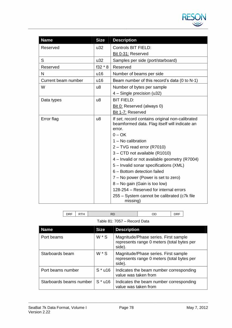
SeaBat 7k Data Format, Volume I Version 2.22
Page 78 May 7, 2012
Name Size Description
Reserved u32 Controls BIT FIELD:
Bit 0-31: Reserved
S u32 Samples per side (port/starboard)
Reserved f32 * 8 Reserved
N u16 Number of beams per side
Current beam number u16 Beam number of this record’s data (0 to N-1)
W u8 Number of bytes per sample
4 – Single precision (u32)
Data types u8 BIT FIELD:
Bit 0: Reserved (always 0)
Bit 1-7: Reserved
Error flag u8 If set, record contains original non-calibrated beamformed data. Flag itself will indicate an error.
0 – OK
1 – No calibration
2 – TVG read error (R7010)
3 – CTD not available (R1010)
4 – Invalid or not available geometry (R7004)
5 – Invalid sonar specifications (XML)
6 – Bottom detection failed
7 – No power (Power is set to zero)
8 – No gain (Gain is too low)
128-254 – Reserved for internal errors
255 – System cannot be calibrated (c7k file missing)
DRF RTH RD OD DRF
Table 81: 7057 – Record Data
Name Size Description
Port beams W * S Magnitude/Phase series. First sample represents range 0 meters (total bytes per side).
Starboards beam W * S Magnitude/Phase series. First sample represents range 0 meters (total bytes per side).
Port beams number S * u16 Indicates the beam number corresponding value was taken from
Starboards beams number S * u16 Indicates the beam number corresponding value was taken from
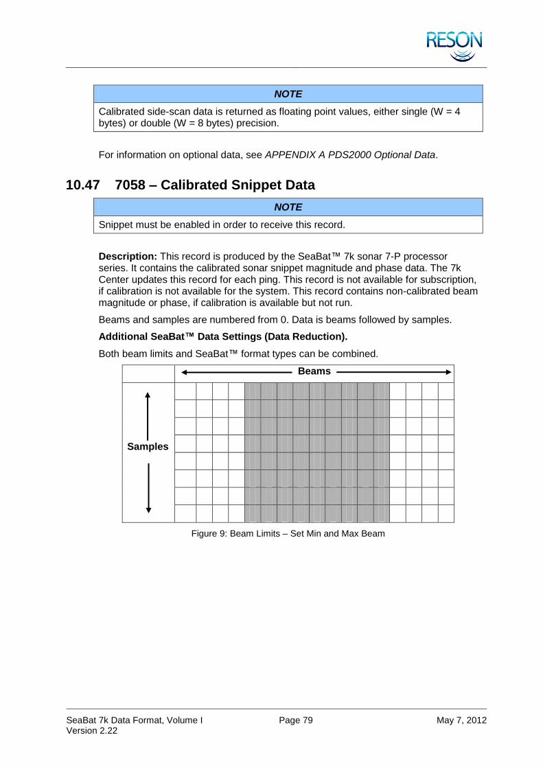
SeaBat 7k Data Format, Volume I Version 2.22
Page 79 May 7, 2012
NOTE
Calibrated side-scan data is returned as floating point values, either single (W = 4 bytes) or double (W = 8 bytes) precision.
For information on optional data, see APPENDIX A PDS2000 Optional Data.
10.47 7058 – Calibrated Snippet Data
NOTE
Snippet must be enabled in order to receive this record.
Description: This record is produced by the SeaBat™ 7k sonar 7-P processor series. It contains the calibrated sonar snippet magnitude and phase data. The 7k Center updates this record for each ping. This record is not available for subscription, if calibration is not available for the system. This record contains non-calibrated beam magnitude or phase, if calibration is available but not run.
Beams and samples are numbered from 0. Data is beams followed by samples.
Additional SeaBat™ Data Settings (Data Reduction).
Both beam limits and SeaBat™ format types can be combined.
Beams
Samples
Figure 9: Beam Limits – Set Min and Max Beam

SeaBat 7k Data Format, Volume I Version 2.22
Page 80 May 7, 2012
Beams
Samples
Figure 10: Sample Limits – Set in dB Around Bottom Detection Point
Data Definition:
DRF RTH RD OD DRF
Table 82: 7058 – Record Type Header
Name Size Description
Sonar Id u64 Sonar serial number
Ping number u32 Sequential number
Multi-ping sequence u16 Flag to indicate multi-ping sequence. Always 0 (zero) if not in multi-ping mode; otherwise this represents the sequence number of the ping in the multi-ping sequence.
Beams u16 Number of beams in the record
Error flag u8 If set, record contains original non-calibrated beamformed data. Flag itself will indicate an error.
0 – OK
1 – No calibration
2 – TVG read error (R7010)
3 – CTD not available (R1010)
4 – Invalid or not available geometry (R7004)
5 – Invalid sonar specifications (XML)
6 – Bottom detection failed (R7006)
7 – No power (Power is set to zero)
8 – No gain (Gain is too low)
128-254 – Reserved for internal errors
255 – System cannot be calibrated (c7k file missing)

SeaBat 7k Data Format, Volume I Version 2.22
Page 81 May 7, 2012
Name Size Description
Control flags u32 Control settings from RC 1113 command
0 – Brightness is required to pass
1 – Colinearity is required to pass
2 – Bottom detection results are used for snippet
3 – Snippet display min. requirements are used
4 – Minimum window size is required
5 – Maximum window size is required
6-31 – Reserved
Reserved u32 * 7 Reserved for future use
DRF RTH RD OD DRF
Table 83: 7058 – Record Data
Name Size Description
Beam descriptor u16 Beam number
Begin sample descriptor
u32 First sample number in beam from transmitter and outward
Bottom detection sample
u32 Bottom detection point in beam from transmitter and outward
End sample descriptor u32 Last sample number in beam from transmitter and outward
… … …
Beam descriptor u16 Beam number
Begin sample descriptor
u32 First sample number in beam from transmitter and outward
Bottom detection sample
u32 Bottom detection point in beam from transmitter and outward
End sample descriptor u32 Last sample number in beam from transmitter and outward
First beam Dynamic
(E-B+1) * f32
Signal intensity series for each sample. Array is populated with samples from transmitter and outward.
… … …
Last beam Dynamic
(E-B+1) * f32
Signal intensity series for each sample. Array is populated with samples from transmitter and outward.
For information on optional data, see APPENDIX A PDS2000 Optional Data.

SeaBat 7k Data Format, Volume I Version 2.22
Page 82 May 7, 2012
10.48 7200 – 7k File Header
Description: First record of 7k data file.
Data Definition:
DRF RTH RD OD DRF
Table 84: 7200 – Record Type Header
Name Size Description
File identifier u128
Version number u16 File format version number
Reserved u16 Reserved
Session identifier u128 User defined session identifier. Used to associate multiple files for a given session.
Record data size u32 Size of record data.
0 – If not present
N u32 Number of devices (N ≥ 0)
Recording name u8 * 64 Null terminated US-ASCII string
Recording program version number
u8 * 16 Null terminated US-ASCII string
User defined name u8 * 64 Null terminated US-ASCII string
Notes u8 * 128 Null terminated US-ASCII string.
DRF RTH RD OD DRF
Table 85: 7200 – Record Data
Name Size Description
Device identifier 0 u32 Identifier for record type of embedded data
System enumerator 0 u16 Identifier for the device enumerator
... ... ...
Device identifier N-1 u32 Identifier for record type of embedded data
System enumerator N-1 u16 Identifier for the device enumerator
10.49 7300 – 7k File Catalog Record
Description: 7k RDR file index record, placed at the end of RDR files.
Data Definition:
DRF RTH RD OD DRF
Table 86: 7300 – Record Type Header
Name Size Description
dwSize u32 Size of this record
wVersion u16 1

SeaBat 7k Data Format, Volume I Version 2.22
Page 83 May 7, 2012
Name Size Description
dwNumRecords u32 Number of records in RDR file
dwReserved u32 Reserved
10.50 7400 – 7k Time Message
Description: This record is used to time-sync the 7k Center. The leap second offset field can be used to flag for leap second inserts ahead of time. The current time is shown in the 7KTIME field of the DRF.
Data Definition:
DRF RTH RD OD DRF
Table 87: 7400 – Record Type Header
Name Size Description
Leap second offset i8 -1, 0 or +1 second for midnight 31 Dec
Pulse flag u8 0 – Message is not associated with hardware pulse
1 – Message preceding hardware pulse
2 – Message following hardware pulse
Port identifier u16 Port number identifier for pulse
Reserved u32 Reserved
Reserved u64 Reserved
NOTE
SeaBat™ 7k Time Records have a reserved number range from 7400 through 7499.
10.51 7500 – 7k Remote Control
Description: This record is used to remotely control SeaBat™ 7k sonar series. It contains the 7-P processor remote control commands. A remote control command is either acknowledged (record 7501) or not acknowledged (record 7502). The record can be subscribed to from the 7k Center. For details about subscribing to records, see section 10 Record Type Definitions. All remote control commands shall be sent to TCP or UDP port 7000 on the 7-P processor.
Data Definition:
DRF RTH RD OD DRF
Table 88: 7500 – Record Type Header
Name Size Description
Remote control ID u32 See separate remote control table for details. See section 10 Record Type Definitions.
Ticket u32 Ticket number. Set by client for control packet matching ACK or NAK packets.
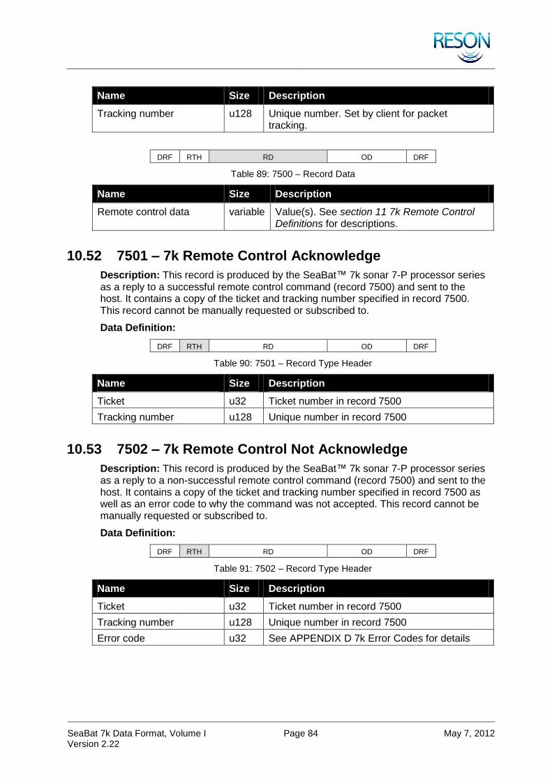
SeaBat 7k Data Format, Volume I Version 2.22
Page 84 May 7, 2012
Name Size Description
Tracking number u128 Unique number. Set by client for packet tracking.
DRF RTH RD OD DRF
Table 89: 7500 – Record Data
Name Size Description
Remote control data variable Value(s). See section 11 7k Remote Control Definitions for descriptions.
10.52 7501 – 7k Remote Control Acknowledge
Description: This record is produced by the SeaBat™ 7k sonar 7-P processor series as a reply to a successful remote control command (record 7500) and sent to the host. It contains a copy of the ticket and tracking number specified in record 7500. This record cannot be manually requested or subscribed to.
Data Definition:
DRF RTH RD OD DRF
Table 90: 7501 – Record Type Header
Name Size Description
Ticket u32 Ticket number in record 7500
Tracking number u128 Unique number in record 7500
10.53 7502 – 7k Remote Control Not Acknowledge
Description: This record is produced by the SeaBat™ 7k sonar 7-P processor series as a reply to a non-successful remote control command (record 7500) and sent to the host. It contains a copy of the ticket and tracking number specified in record 7500 as well as an error code to why the command was not accepted. This record cannot be manually requested or subscribed to.
Data Definition:
DRF RTH RD OD DRF
Table 91: 7502 – Record Type Header
Name Size Description
Ticket u32 Ticket number in record 7500
Tracking number u128 Unique number in record 7500
Error code u32 See APPENDIX D 7k Error Codes for details

SeaBat 7k Data Format, Volume I Version 2.22
Page 85 May 7, 2012
10.54 7503 – Remote Control Sonar Settings
Description: This record is produced by the SeaBat™ 7k Sonar. It contains the remote control sonar settings. The 7k Center updates this record for each ping. For multi-ping only one record is produced for the whole sequence .The record can be manually requested or subscribed to from the 7k Center. For details about requesting and subscribing to records, see section 10.51 7500 – 7k Remote Control together with section 11 7k Remote Control Definitions.
Data Definition:
DRF RTH RD OD DRF
Table 92: 7503 – Record Type Header
Name Size Description
Sonar Id u64 Sonar serial number
Ping number u32 Sequential number
Frequency f32 Center transmit frequency in Hertz
Sample rate f32 Sample rate in Hertz
Receiver bandwidth f32 In Hertz
Tx pulse width f32 Seconds of pulse
Tx pulse type identifier u32 0 – CW
1 – Linear chirp
2 – Multi-ping 2
3 – Multi-ping 4
Tx pulse envelope identifier
u32 0 – Tapered rectangular
1 – Tukey
Tx pulse envelope parameter
f32 Pulse envelop shading. Some envelopes don’t use this parameter.
Tx pulse reserved u32 Additional pulse information
Max ping rate f32 Maximum ping rate in pings per second
Ping period f32 Seconds since last ping
Range selection f32 Range selection in meters
Power selection f32 Power selection in dB/Pa
Gain selection f32 Gain selection in dB

SeaBat 7k Data Format, Volume I Version 2.22
Page 86 May 7, 2012
Name Size Description
Control flags u32 BIT FIELD:
Bit 0-3: Auto range method
Bit 4-7: Auto bottom detection filter method
Bit 8: Bottom detection range filter enabled.
Bit 9: Bottom detection depth filter enabled
Bit 10: Receiver gain method Auto Gain
Bit 11: Receiver gain method Fixed Gain
Bit 12: Receiver gain method Reserved
Bit 13-14: Reserved
Bit 15:
0 – System inactive
1 – Active
Bit 16-21: Reserved for bottom detection
Bit 22: Adaptive gate
1 – Enabled
Bit 23: Adaptive gate depth filter
1 - Enabled
Bit 24: Trigger Out
1 – Enabled
Bit 25 Trigger In Edge
0 – Positive
1 – Negative
Bit 26: PPS Edge
0 – Positive
1 – Negative
Bit 27: Reserved
Bit 28-29: Reserved for Calibration
Bit 30: Reserved
Bit 31:
0 – 7K
1 – Simulator
Projector identifier u32 Projector selection
Projector beam steering angle vertical
f32 In radians
Projector beam steering angle horizontal
f32 In radians
Projector beam -3dB beam width vertical
f32 In radians
Projector beam -3dB beam width horizontal
f32 In radians
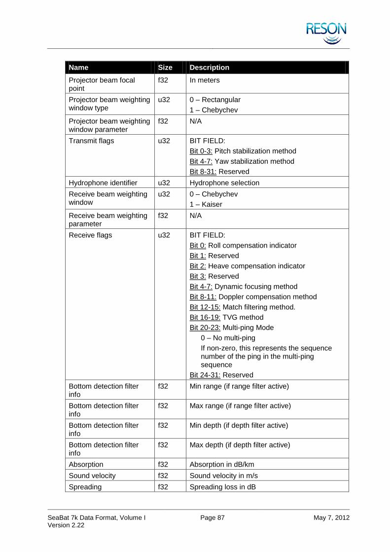
SeaBat 7k Data Format, Volume I Version 2.22
Page 87 May 7, 2012
Name Size Description
Projector beam focal point
f32 In meters
Projector beam weighting window type
u32 0 – Rectangular
1 – Chebychev
Projector beam weighting window parameter
f32 N/A
Transmit flags u32 BIT FIELD:
Bit 0-3: Pitch stabilization method
Bit 4-7: Yaw stabilization method
Bit 8-31: Reserved
Hydrophone identifier u32 Hydrophone selection
Receive beam weighting window
u32 0 – Chebychev
1 – Kaiser
Receive beam weighting parameter
f32 N/A
Receive flags u32 BIT FIELD:
Bit 0: Roll compensation indicator
Bit 1: Reserved
Bit 2: Heave compensation indicator
Bit 3: Reserved
Bit 4-7: Dynamic focusing method
Bit 8-11: Doppler compensation method
Bit 12-15: Match filtering method.
Bit 16-19: TVG method
Bit 20-23: Multi-ping Mode
0 – No multi-ping
If non-zero, this represents the sequence number of the ping in the multi-ping sequence
Bit 24-31: Reserved
Bottom detection filter info
f32 Min range (if range filter active)
Bottom detection filter info
f32 Max range (if range filter active)
Bottom detection filter info
f32 Min depth (if depth filter active)
Bottom detection filter info
f32 Max depth (if depth filter active)
Absorption f32 Absorption in dB/km
Sound velocity f32 Sound velocity in m/s
Spreading f32 Spreading loss in dB
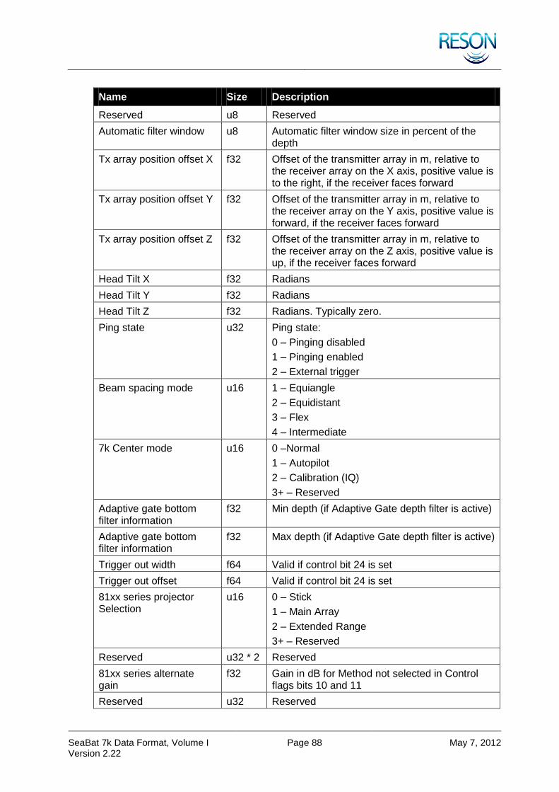
SeaBat 7k Data Format, Volume I Version 2.22
Page 88 May 7, 2012
Name Size Description
Reserved u8 Reserved
Automatic filter window u8 Automatic filter window size in percent of the depth
Tx array position offset X f32 Offset of the transmitter array in m, relative to the receiver array on the X axis, positive value is to the right, if the receiver faces forward
Tx array position offset Y f32 Offset of the transmitter array in m, relative to the receiver array on the Y axis, positive value is forward, if the receiver faces forward
Tx array position offset Z f32 Offset of the transmitter array in m, relative to the receiver array on the Z axis, positive value is up, if the receiver faces forward
Head Tilt X f32 Radians
Head Tilt Y f32 Radians
Head Tilt Z f32 Radians. Typically zero.
Ping state u32 Ping state:
0 – Pinging disabled
1 – Pinging enabled
2 – External trigger
Beam spacing mode u16 1 – Equiangle
2 – Equidistant
3 – Flex
4 – Intermediate
7k Center mode u16 0 –Normal
1 – Autopilot
2 – Calibration (IQ)
3+ – Reserved
Adaptive gate bottom filter information
f32 Min depth (if Adaptive Gate depth filter is active)
Adaptive gate bottom filter information
f32 Max depth (if Adaptive Gate depth filter is active)
Trigger out width f64 Valid if control bit 24 is set
Trigger out offset f64 Valid if control bit 24 is set
81xx series projector Selection
u16 0 – Stick
1 – Main Array
2 – Extended Range
3+ – Reserved
Reserved u32 * 2 Reserved
81xx series alternate gain
f32 Gain in dB for Method not selected in Control flags bits 10 and 11
Reserved u32 Reserved
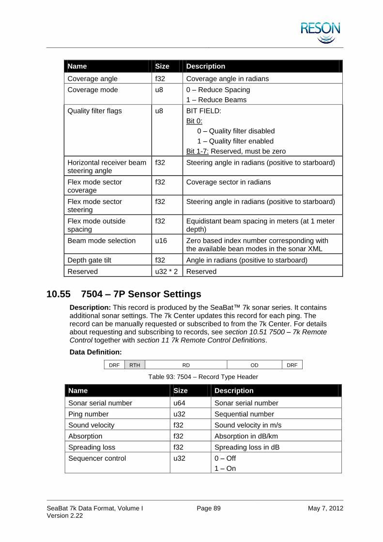
SeaBat 7k Data Format, Volume I Version 2.22
Page 89 May 7, 2012
Name Size Description
Coverage angle f32 Coverage angle in radians
Coverage mode u8 0 – Reduce Spacing
1 – Reduce Beams
Quality filter flags u8 BIT FIELD:
Bit 0:
0 – Quality filter disabled
1 – Quality filter enabled
Bit 1-7: Reserved, must be zero
Horizontal receiver beam steering angle
f32 Steering angle in radians (positive to starboard)
Flex mode sector coverage
f32 Coverage sector in radians
Flex mode sector steering
f32 Steering angle in radians (positive to starboard)
Flex mode outside spacing
f32 Equidistant beam spacing in meters (at 1 meter depth)
Beam mode selection u16 Zero based index number corresponding with the available bean modes in the sonar XML
Depth gate tilt f32 Angle in radians (positive to starboard)
Reserved u32 * 2 Reserved
10.55 7504 – 7P Sensor Settings
Description: This record is produced by the SeaBat™ 7k sonar series. It contains additional sonar settings. The 7k Center updates this record for each ping. The record can be manually requested or subscribed to from the 7k Center. For details about requesting and subscribing to records, see section 10.51 7500 – 7k Remote Control together with section 11 7k Remote Control Definitions.
Data Definition:
DRF RTH RD OD DRF
Table 93: 7504 – Record Type Header
Name Size Description
Sonar serial number u64 Sonar serial number
Ping number u32 Sequential number
Sound velocity f32 Sound velocity in m/s
Absorption f32 Absorption in dB/km
Spreading loss f32 Spreading loss in dB
Sequencer control u32 0 – Off
1 – On

SeaBat 7k Data Format, Volume I Version 2.22
Page 90 May 7, 2012
Name Size Description
Motion sensor format u8 0 – TSS1
1 – SIMRAD EM1000
2 – SIMRAD EM3000
3 – NMEA $PASHR
4 – OCTANS TAH
5+ – Reserved
Motion Sensor Baud Rate u8 0 – 4800
1 – 9600
2 – 14400
3 – 19200
4 – 28800
5 – 38400
6 – 56000
7 – 57600
8 – 115200
9+ – Reserved
Motion Sensor Parity u8 0 – None
1 – Even
2 – Odd
3 – Space
4 – Mark
5+ – Reserved
Motion Sensor Data Bits u8 0 – 5 bits
1 – 6 bits
2 – 7 bits
3 – 8 bits
4+ – Reserved
Motion Sensor Stop Bits u8 0 – 1 bit
1 – 2 bits
2+ – Reserved
Orientation u8 0 – Port Up
1 – Port Down
Reserved u8 Reserved
Motion latency f32 Motion sensor latency in seconds Valid range 0 – 0.050
Reserved u8 Reserved
SV manual override u8 Non-zero if manual override of SV in effect
Active enumerator u16 Enumerator of pinging system
Active device ID u32 Device ID of pinging system

SeaBat 7k Data Format, Volume I Version 2.22
Page 91 May 7, 2012
Name Size Description
System mode u32 0 – Manual (normal) mode
1 – AutoPilot mode
2 – I&Q (normalization) mode
3 – Playback mode
4+ – Reserved
Reserved u32 * 123 Reserved
10.56 7510 – SV Filtering
Description: This record is generated every time a surface sound velocity value is received by the 7k Center either via record 7610 or remote control command 7610. A filtered sound velocity will be generated. For details about requesting and subscribing to records, see section 10.51 7500 – 7k Remote Control together with section 11 7k Remote Control Definitions.
Data Definition:
DRF RTH RD OD DRF
Table 94: 7510 – Record Type Header
Name Size Description
Sensor SV f32 Surface sound velocity reported by sensor
If ‘Filter’ value is either 0 (no value) or 128 (manual), Sensor SV is set to 0 (zero).
Filtered SV f32 Filtered sound velocity value used
Filter u8 0 – No value; no sound velocity value was received by the 7k Center
1 – Transparent; no filtering
2 – Light filter
3 – Normal filter
4 – SVP70 Wizard
5-127 – Reserved
128 – Manual input
NOTE
Record 7510 is not generated if surface sound velocity value is received via record 7610 while 7k Center is in manual overwrite mode.
NOTE
SV Filter is now reset every time a manual value is received via the remote control command 7610. Manual values are never filtered.

SeaBat 7k Data Format, Volume I Version 2.22
Page 92 May 7, 2012
10.57 7511 – System Lock Status
Description: This record informs the clients about SeaBat™ 7k being used exclusively by single client. No other client will be able to change any parameters of the system while it is locked. The remote control commands will be not acknowledged with the error code 0x700B (Remote Command Denied). The 7k Center updates and publishes this record when the status has changed. The record can be manually requested or subscribed to from the 7k Center. For details about requesting and subscribing to records, see section 10.51 7500 – 7k Remote Control together with section 11 7k Remote Control Definitions.
Data Definition:
DRF RTH RD OD DRF
Table 95: 7511 – Record Type Header
Name Size Description
System lock u16 0 – System is not locked
1 – System is locked
Client IP u32 IP Address of the client that has exclusive control of the system. 127.0.0.1 (0x7F000001) is reported for local clients (those that are running on the same host as 7k Center) regardless of the type of the connection (TCP or Shared Memory). This field is not valid if system is not locked.
Reserved u32 * 8 Reserved for future use
NOTE
This record is unidirectional. See remote command 1503 in section 11 7k Remote Control Definitions for how to gain exclusive control of the system.
10.58 7610 – 7k Sound Velocity
Description: This record can be used to set the SeaBat™ 7k sonar series systems current sound velocity value. The record can be manually requested or subscribed to from the 7k Center. For details about requesting and subscribing to records, see section 10.51 7500 – 7k Remote Control together with section 11 7k Remote Control Definitions.
Data Definition:
DRF RTH RD OD DRF
Table 96: 7610 – Record Type Header
Name Size Description
Sound velocity f32 In meters/second
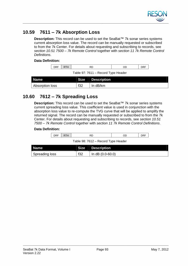
SeaBat 7k Data Format, Volume I Version 2.22
Page 93 May 7, 2012
10.59 7611 – 7k Absorption Loss
Description: This record can be used to set the SeaBat™ 7k sonar series systems current absorption loss value. The record can be manually requested or subscribed to from the 7k Center. For details about requesting and subscribing to records, see section 10.51 7500 – 7k Remote Control together with section 11 7k Remote Control Definitions.
Data Definition:
DRF RTH RD OD DRF
Table 97: 7611 – Record Type Header
Name Size Description
Absorption loss f32 In dB/km
10.60 7612 – 7k Spreading Loss
Description: This record can be used to set the SeaBat™ 7k sonar series systems current spreading loss value. This coefficient value is used in conjunction with the absorption loss value to re-compute the TVG curve that will be applied to amplify the returned signal. The record can be manually requested or subscribed to from the 7k Center. For details about requesting and subscribing to records, see section 10.51 7500 – 7k Remote Control together with section 11 7k Remote Control Definitions.
Data Definition:
DRF RTH RD OD DRF
Table 98: 7612 – Record Type Header
Name Size Description
Spreading loss f32 In dB (0.0-60.0)

SeaBat 7k Data Format, Volume I Version 2.22
Page 94 May 7, 2012
11 7K REMOTE CONTROL DEFINITIONS
11.1 Overview
This is a detailed discussion of the Record Data section of the 7500 record. The SeaBat™ 7k series system supports all commands or a subset of the below commands.
Table 99: 7k Remote Control Definitions
Identifier Description Possible Return Records
1000 Shutdown 7501, 7502
1001 Reboot 7501, 7502
1002 Calibrate 7501, 7502
1003 Range 7501, 7502
1004 Max ping rate 7501, 7502
1005 Transmit power 7501, 7502
1006 Pulse length 7501, 7502
1007 Pulse type 7501, 7502
1008 Receiver gain 7501, 7502
1009 Bottom detection mask 7501, 7502
1010 Bottom detection filter information 7501, 7502
1011 Projector selection 7501, 7502
1012 Reserved for projector beam stabilization
1013 Reserved for receive beam stabilization
1014 Reserved for 7k Center mode selection
1015 Reserved for hydrophone selection
1016 Bottom detection adaptive gate window and filters
1017 Receiver gain type
1020 Transmit pulse envelope identifier
1021 Projector beam steering 7501, 7502
1022 Projector beam widths 7501, 7502
1023 Reserved for projector beam focal point
1024 Reserved for projector beam weighting
1025 Reserved for receiver beam weighting
1026 Reserved for system center frequency 7501, 7502
1027 Transmit frequencies for chirps 7501, 7502
1028 Head tilt
1029 Projector position relative to receiver 7501, 7502
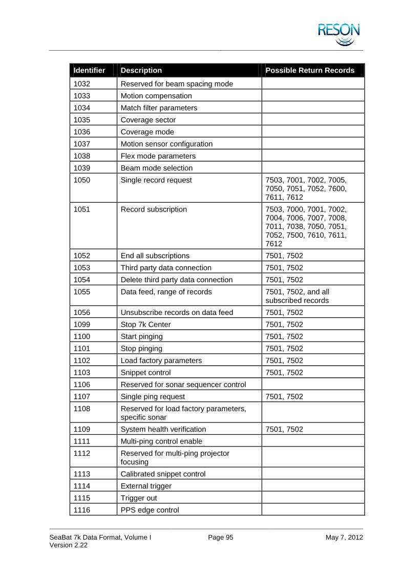
SeaBat 7k Data Format, Volume I Version 2.22
Page 95 May 7, 2012
Identifier Description Possible Return Records
1032 Reserved for beam spacing mode
1033 Motion compensation
1034 Match filter parameters
1035 Coverage sector
1036 Coverage mode
1037 Motion sensor configuration
1038 Flex mode parameters
1039 Beam mode selection
1050 Single record request 7503, 7001, 7002, 7005, 7050, 7051, 7052, 7600, 7611, 7612
1051 Record subscription 7503, 7000, 7001, 7002, 7004, 7006, 7007, 7008, 7011, 7038, 7050, 7051, 7052, 7500, 7610, 7611, 7612
1052 End all subscriptions 7501, 7502
1053 Third party data connection 7501, 7502
1054 Delete third party data connection 7501, 7502
1055 Data feed, range of records 7501, 7502, and all subscribed records
1056 Unsubscribe records on data feed 7501, 7502
1099 Stop 7k Center 7501, 7502
1100 Start pinging 7501, 7502
1101 Stop pinging 7501, 7502
1102 Load factory parameters 7501, 7502
1103 Snippet control 7501, 7502
1106 Reserved for sonar sequencer control
1107 Single ping request 7501, 7502
1108 Reserved for load factory parameters, specific sonar
1109 System health verification 7501, 7502
1111 Multi-ping control enable
1112 Reserved for multi-ping projector focusing
1113 Calibrated snippet control
1114 External trigger
1115 Trigger out
1116 PPS edge control

SeaBat 7k Data Format, Volume I Version 2.22
Page 96 May 7, 2012
Identifier Description Possible Return Records
1117 Quality filter settings
1118 Snippet control
1138 Element limit control
1200 Start recording 7501, 7502
1201 Stop recording/playback 7501, 7502
1202 Start playback 7501, 7502
1203 Reserved for data storage delete
1204 Data storage status request
1205 Reserved for get catalog 7502
1206 Set warning thresholds 7501, 7502
1207 Set recording directory 7501, 7502
1209 Set filtering 7501
1300-1305 Reserved
1400 Autopilot table update
1401 Autopilot algorithm parameters update (not described in the documentation)
7501, 7502
1503 Reserved for system lock
1509 System health check (not described in the documentation)
7501, 7502
7041 R7041 setup
7610 Manual sound velocity
11.2 1000 – Shutdown
Description: Software and firmware halt followed by power shutdown to dry and wet hardware.
This command has no parameters.
11.3 1001 – Reboot
Software and firmware reset.
This command has no parameters.
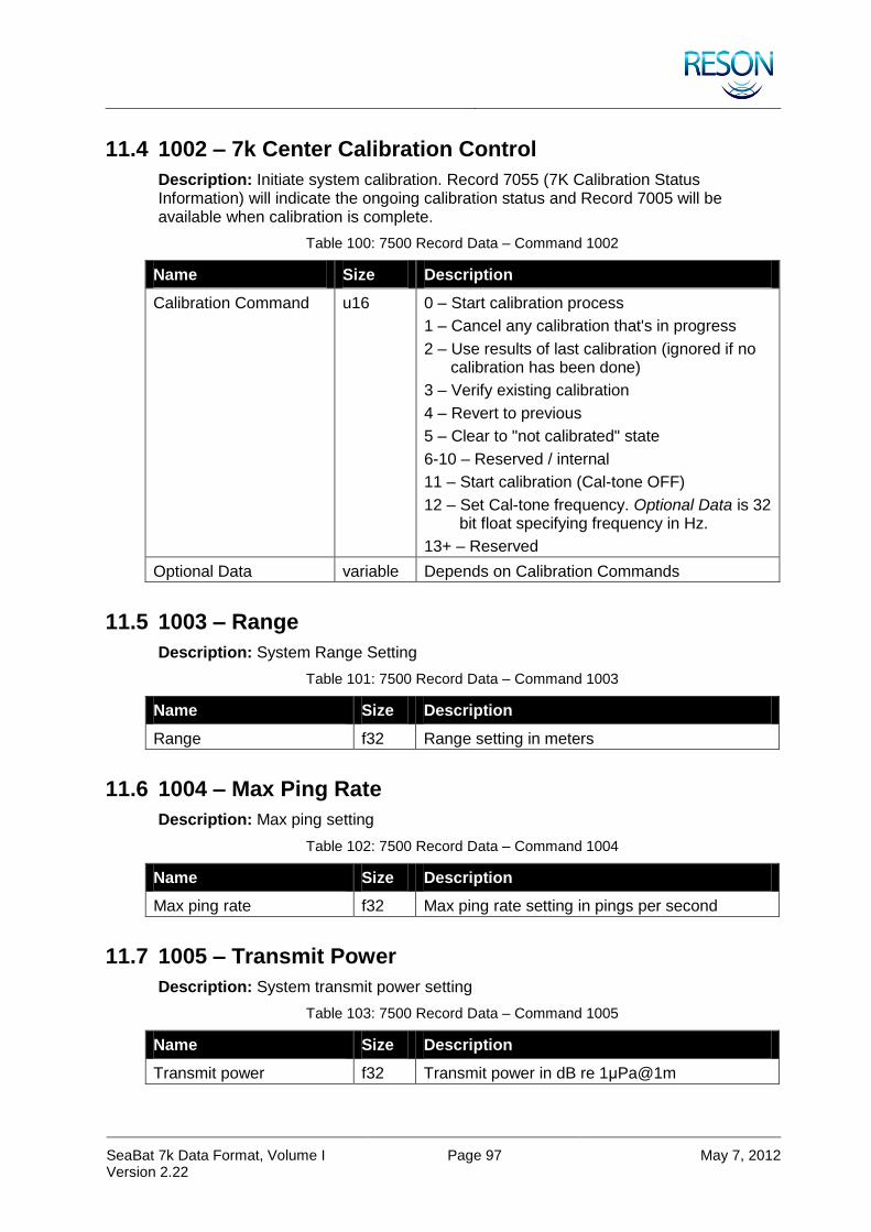
SeaBat 7k Data Format, Volume I Version 2.22
Page 97 May 7, 2012
11.4 1002 – 7k Center Calibration Control
Description: Initiate system calibration. Record 7055 (7K Calibration Status Information) will indicate the ongoing calibration status and Record 7005 will be available when calibration is complete.
Table 100: 7500 Record Data – Command 1002
Name Size Description
Calibration Command u16 0 – Start calibration process
1 – Cancel any calibration that's in progress
2 – Use results of last calibration (ignored if no calibration has been done)
3 – Verify existing calibration
4 – Revert to previous
5 – Clear to "not calibrated" state
6-10 – Reserved / internal
11 – Start calibration (Cal-tone OFF)
12 – Set Cal-tone frequency. Optional Data is 32 bit float specifying frequency in Hz.
13+ – Reserved
Optional Data variable Depends on Calibration Commands
11.5 1003 – Range
Description: System Range Setting
Table 101: 7500 Record Data – Command 1003
Name Size Description
Range f32 Range setting in meters
11.6 1004 – Max Ping Rate
Description: Max ping setting
Table 102: 7500 Record Data – Command 1004
Name Size Description
Max ping rate f32 Max ping rate setting in pings per second
11.7 1005 – Transmit Power
Description: System transmit power setting
Table 103: 7500 Record Data – Command 1005
Name Size Description
Transmit power f32 Transmit power in dB re 1μPa@1m

SeaBat 7k Data Format, Volume I Version 2.22
Page 98 May 7, 2012
11.8 1006 – Pulse Length
Description: System transmitter pulse length setting
Table 104: 7500 Record Data – Command 1006
Name Size Description
Transmit pulse width f32 Transmit pulse length in seconds
11.9 1007 – Pulse Type
Description: System transmitter pulse type.
This command is only available for selected systems.
Table 105: 7500 Record Data – Command 1007
Name Size Description
Transmit pulse type u32 0 – CW
1 – Linear chirp
11.10 1008 – Receiver Gain
Description: System receiver gain.
Table 106: 7500 Record Data – Command 1008
Name Size Description
Receiver gain f32 Gain selection in dB
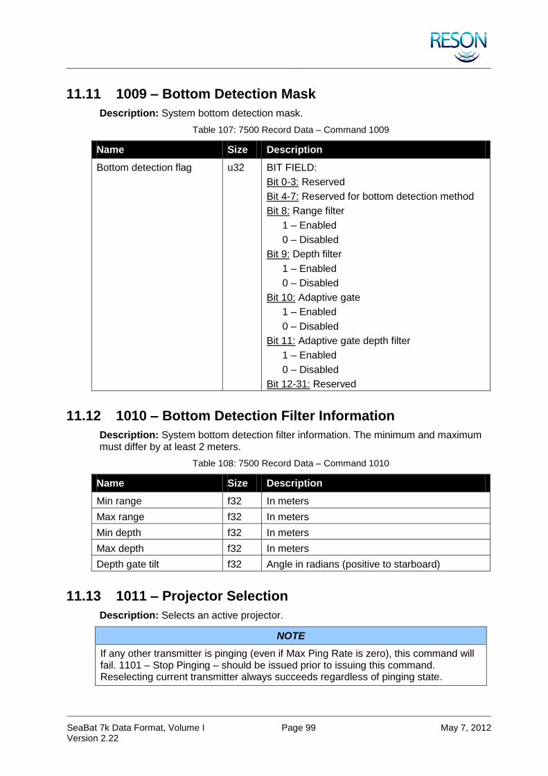
SeaBat 7k Data Format, Volume I Version 2.22
Page 99 May 7, 2012
11.11 1009 – Bottom Detection Mask
Description: System bottom detection mask.
Table 107: 7500 Record Data – Command 1009
Name Size Description
Bottom detection flag u32 BIT FIELD:
Bit 0-3: Reserved
Bit 4-7: Reserved for bottom detection method
Bit 8: Range filter
1 – Enabled
0 – Disabled
Bit 9: Depth filter
1 – Enabled
0 – Disabled
Bit 10: Adaptive gate
1 – Enabled
0 – Disabled
Bit 11: Adaptive gate depth filter
1 – Enabled
0 – Disabled
Bit 12-31: Reserved
11.12 1010 – Bottom Detection Filter Information
Description: System bottom detection filter information. The minimum and maximum must differ by at least 2 meters.
Table 108: 7500 Record Data – Command 1010
Name Size Description
Min range f32 In meters
Max range f32 In meters
Min depth f32 In meters
Max depth f32 In meters
Depth gate tilt f32 Angle in radians (positive to starboard)
11.13 1011 – Projector Selection
Description: Selects an active projector.
NOTE
If any other transmitter is pinging (even if Max Ping Rate is zero), this command will fail. 1101 – Stop Pinging – should be issued prior to issuing this command. Reselecting current transmitter always succeeds regardless of pinging state.

SeaBat 7k Data Format, Volume I Version 2.22
Page 100 May 7, 2012
Table 109: 7500 Record Data – Command 1011
Name Size Description
Force projector u32 If set to -1 (0xffff) the projector selection will be forced, by issuing stop pinging command to all other projectors
8K wet ends – projector selection:
0 – Stick
1 – Main array
2 – Extended range
3+ – Reserved
11.14 1016 – Bottom Detection Adaptive Gate Window and Filters
Description: Controls the bottom detection adaptive gate operation. The nadir search minimum and maximum values are used only if the Adaptive Gate Depth Filter option is enabled (See section 11.11 1009 – Bottom Detection Mask). The minimum and maximum must differ by at least 2 meters.
Table 110: 7500 Record Data – Command 1016
Name Size Description
Window size i32 Bottom detection gate size as a percentage of the approximate nadir depth. Valid range is 1-100.
Search minimum f32 Minimum depth for initial bottom detection on nadir beam (meters)
Search maximum f32 Maximum depth for initial bottom detection on nadir beam (meters)
11.15 1017 – Receiver Gain Type
Description: Sets the receiver gain type.
This command is only available for selected systems.
Table 111: 7500 Record Data – Command 1016
Name Size Description
Gain type u32 0 – TVG
1 – Reserved for auto gain
2 – Fixed
3+ – Reserved
Reserved u32 * 4 Reserved
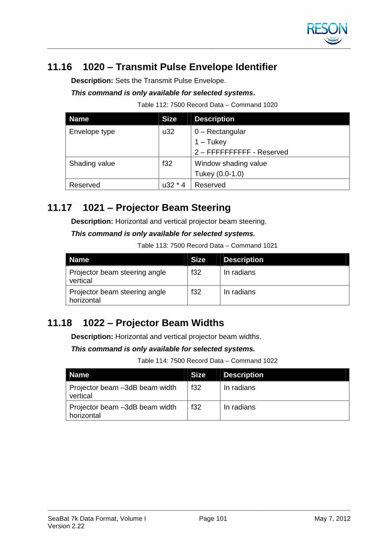
SeaBat 7k Data Format, Volume I Version 2.22
Page 101 May 7, 2012
11.16 1020 – Transmit Pulse Envelope Identifier
Description: Sets the Transmit Pulse Envelope.
This command is only available for selected systems.
Table 112: 7500 Record Data – Command 1020
Name Size Description
Envelope type u32 0 – Rectangular
1 – Tukey
2 – FFFFFFFFFF - Reserved
Shading value f32 Window shading value
Tukey (0.0-1.0)
Reserved u32 * 4 Reserved
11.17 1021 – Projector Beam Steering
Description: Horizontal and vertical projector beam steering.
This command is only available for selected systems.
Table 113: 7500 Record Data – Command 1021
Name Size Description
Projector beam steering angle vertical
f32 In radians
Projector beam steering angle horizontal
f32 In radians
11.18 1022 – Projector Beam Widths
Description: Horizontal and vertical projector beam widths.
This command is only available for selected systems.
Table 114: 7500 Record Data – Command 1022
Name Size Description
Projector beam –3dB beam width vertical
f32 In radians
Projector beam –3dB beam width horizontal
f32 In radians

SeaBat 7k Data Format, Volume I Version 2.22
Page 102 May 7, 2012
11.19 1027 – Transmit Frequencies for Chirps
Description: Transmit pulse start and stop frequencies.
This command is only available for selected systems.
Table 115: 7500 Record Data – Command 1027
Name Size Description
Start frequency f32 In Hz
Stop frequency f32 In Hz
11.20 1033 – Motion Compensation
Description: Sets motion compensation options. Roll compensation status is reported for each ping in the receive flags field of the 7000 and 7503 records. Pitch compensation status is reported for each ping in the transmit flags field of the 7000 and 7503 records. Motion compensation capability varies depending on system type.
Table 116: 7500 Record Data – Command 1033
Name Size Description
Roll u8 0 – OFF
>0 – ON
Pitch u8 0 – OFF
>0 – ON
Heave u8 N/A
Speed u8 N/A
Reserved u8 * 8 Reserved
11.21 1034 – Match Filter Parameters
Description: Sets the match filter parameters.
This command is only available for selected systems.
Table 117: 7500 Record Data – Command 1034
Name Size Description
Window type u32 0 – Rectangular
1 – Kaiser
2 – Reserved for Hamming
3 – Reserved for Blackmann
4 – Reserved for Triangular
5 – Reserved for X (Taylor)
6 – FFFFFFFFFF – Reserved
Shading value f32 Window shading value
Reserved u32 * 4 Reserved

SeaBat 7k Data Format, Volume I Version 2.22
Page 103 May 7, 2012
11.22 1035 – Coverage Sector
Description: Sets the current coverage sector.
This command is only available for selected systems.
Table 118: 7500 Record Data – Command 1035
Name Size Description
Coverage sector f32 Coverage sector in radians
Horizontal receiver beam steering angle
f32 Steering angle in radians (positive to starboard)
11.23 1036 – Coverage Mode
Description: Sets the current coverage mode.
This command is only available for selected systems.
Table 119: 7500 Record Data – Command 1036
Name Size Description
Coverage mode u8 0 – Reduce spacing
1 – Reduce beams
11.24 1037 – Motion Sensor Configuration
Description: Sets the motion sensor configuration.
This command is only available for selected systems.
Table 120: 7500 Record Data – Command 1037
Name Size Description
Format u8 0 – TSS1
1 – SIMRAD EM1000
2 – SIMRAD EM3000
3 – NMEA $PASHR
4 – OCTANS TAH
Baud u8 0 – 4800
1 – 9600
2 – 14400
3 – 19200
4 – 28800
5 – 38400
6 – 56000
7 – 57600
8 – 115200

SeaBat 7k Data Format, Volume I Version 2.22
Page 104 May 7, 2012
Name Size Description
Parity u8 0 – None
1 – Even
2 – Odd
3 – Space
4 – Mark
Data Bits u8 0 – 5 bits
1 – 6 bits
2 – 7 bits
3 – 8 bits
Stop Bits u8 0 – 1 bit
1 – 2 bits
Orientation u8 0 – Port Up
1 – Port Down
Reserved u8 Reserved
Motion Latency f32 Motion latency in seconds Valid range is 0 – 0.050
Reserved u8 * 20 Reserved
11.25 1038 – Flex Mode Parameters
Description: Set the flex mode parameters.
Table 121: 7500 Record Data – Command 1038
Name Size Description
Flex mode sector coverage
f32 Coverage sector in radians
Flex mode sector steering f32 Sector steering angle in radians (positive to starboard)
Flex mode outside spacing
f32 Equidistant beam spacing in meters (at 1 meter depth)
11.26 1039 – Beam Mode Selection
Description: Set the beam mode selection.
Table 122: 7500 Record Data – Command 1039
Name Size Description
Beam mode selection u16 Zero based index number corresponding with the available beam modes in the sonar XML

SeaBat 7k Data Format, Volume I Version 2.22
Page 105 May 7, 2012
11.27 1050 – Single Record Request
Description: Request latest record.
Table 123: 7500 Record Data – Command 1050
Name Size Description
Record type u32 Possible responses:
7501 – Followed by the requested record, will be one of the following: 1002, 1003, 1004, 1005, 1006, 1007, 1008, 1009, 1010, 1011, 1012, 1013, 1014, 1015, 1016, 1050, 7001, 7002, 7004, 7005, 7022, 7050, 7052, 7400, 7503, 7610, 7611, 7612.
7502 (NACK)
11.28 1051 – Record Subscription
Description: Subscribe to records. The host is responsible to keep this connection alive as well as re-establish a lost connection to the 7-P processor.
Table 124: 7500 Record Data – Command 1051
Name Size Description
N u32 Number of records
Array of record numbers u32 * N Possible responses:
7501 – Followed by the subscribed record(s), will be one or more of the following: 7503, 7000, 7002, 7004, 7006, 7007, 7008, 7011, 7050, 7051, 7052, 7055
7502 (NACK)
11.29 1052 – End All Subscriptions
Description: Unsubscribe to all records.
This command has no parameters.
11.30 1053 – Third Party Data Connection
Description: Add UDP or TCP connection to 7k Center, with specification of records to subscribe to.
Table 125: 7500 Record Data – Command 1053
Name Size Description
Address u32 IP address (Host Byte Data Order)
Port u16 Port number
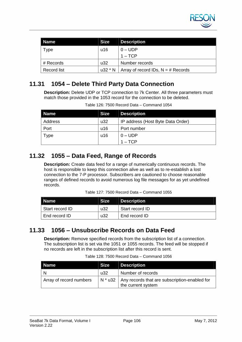
SeaBat 7k Data Format, Volume I Version 2.22
Page 106 May 7, 2012
Name Size Description
Type u16 0 – UDP
1 – TCP
# Records u32 Number records
Record list u32 * N Array of record IDs, N = # Records
11.31 1054 – Delete Third Party Data Connection
Description: Delete UDP or TCP connection to 7k Center. All three parameters must match those provided in the 1053 record for the connection to be deleted.
Table 126: 7500 Record Data – Command 1054
Name Size Description
Address u32 IP address (Host Byte Data Order)
Port u16 Port number
Type u16 0 – UDP
1 – TCP
11.32 1055 – Data Feed, Range of Records
Description: Create data feed for a range of numerically continuous records. The host is responsible to keep this connection alive as well as to re-establish a lost connection to the 7-P processor. Subscribers are cautioned to choose reasonable ranges of defined records to avoid numerous log file messages for as yet undefined records.
Table 127: 7500 Record Data – Command 1055
Name Size Description
Start record ID u32 Start record ID
End record ID u32 End record ID
11.33 1056 – Unsubscribe Records on Data Feed
Description: Remove specified records from the subscription list of a connection. The subscription list is set via the 1051 or 1055 records. The feed will be stopped if no records are left in the subscription list after this record is sent.
Table 128: 7500 Record Data – Command 1056
Name Size Description
N u32 Number of records
Array of record numbers N * u32 Any records that are subscription-enabled for the current system

SeaBat 7k Data Format, Volume I Version 2.22
Page 107 May 7, 2012
11.34 1099 – Stop 7k Center
Description: Causes 7k Center process to stop. Should always be acknowledged.
This command has no parameters.
11.35 1100 – Start Pinging
Description: Start continuous pinging. (Pinging will not start if the Max Ping Rate is set to zero.)
This command has no parameters.
11.36 1101 – Stop Pinging
Description: Stop pinging.
This command has no parameters.
11.37 1102 – Load Factory Parameters
Description: Load Factory Parameters from disk.
This command has no parameters.
11.38 1103 – Snippet Control
Description: Limit record 7028’s sample range to a window around the bottom detection ranges.
NOTE
Have the same working as 7008 record (i.e. obsolete and will cause undefined behavior if used in conjunction with 7028 record).
Table 129: 7500 Record Data – Command 1103
Name Size Description
Enable u32 0 – Disable snippet sample limitation
1 – Enable snippet sample limitation
Window size u32 Number of samples around bottom detection for each beam
11.39 1107 – Single Ping Request
Description: Request for a single ping.
This command has no parameters.
NOTE
This request will halt continuous pinging if it has been started.

SeaBat 7k Data Format, Volume I Version 2.22
Page 108 May 7, 2012
11.40 1109 – System Health Verification
Description: Request System Health snapshot text file to be created. The file name is created according to section 8.2 File Nomenclature with a .txt extension.
File is named “7kSystemHealth. The file will be created in the 7k Center executable directory. For remote connections (UDP/TCP) with the SeaBat UI, an additional file will be created in the SeaBat executable directory.
This command has no parameters.
11.41 1111 – Multi-ping Control Enable
Description: Set multi-ping control parameters. Note that if the number of pings field is 0 or 1, then multi-ping mode is turned OFF, and the begin frequency and spacing fields are ignored. Multi-ping capability varies depending on system type.
Table 130: 7500 Record Data – Command 1111
Name Size Description
Number of pings in sequence
u16 0, 1 – Single ping mode (default)
2 – 2 pings
4 – 4 pings
Begin frequency u32 First ping frequency (Hz)
Spacing i32 Frequency spacing (Hz, may be negative)
NOTE
Currently the Begin Frequency and Spacing fields are not used. Each ping in the multi-ping sequence is spaced evenly about the base (center) frequency, and the spacing is not adjustable. E.g. for 2 ping mode, frequency for ping #1 = center frequency – (fixed spacing / 2); frequency for ping #2 = center frequency + (fixed spacing / 2). For instance, the center frequency is 400kHz, the spacing is set at 30kHz then ping#1 is 385kHz and ping#2 is 415kHz. The actual frequency value for each ping is reported in the 7000 record, which is generated for each ping in the multi-ping sequence.
11.42 1113 – Calibrated Snippet Control
Description: Limit record 7058’s sample range to a window around the bottom detection ranges.
Table 131: 7500 Record Data – Command 1113
Name Size Description
Enable u16 0 – Disable snippet sample limitation
1 – Enable snippet sample limitation
Window size f32 Number of samples around bottom detection for each beam

SeaBat 7k Data Format, Volume I Version 2.22
Page 109 May 7, 2012
Name Size Description
Flags u32 BIT FIELD:
Bit 0: Bottom detection window selected
Bit 1: Snippet display window selected
Bit 2: Quality control
Bit 3: Minimum window size is required
Bit 4: Maximum window size is required
Bit 6-31: Reserved
Flag u8 BIT FIELD:
Bit 0: Require brightness quality to pass
Bit 1: Require colinearity quality to pass
Bit 2-7: Reserved
Minimum window size u32 Minimum number of samples around bottom detection for each beam
Maximum window size u32 Maximum number of samples around bottom detection for each beam
11.43 1114 – External Trigger
Description: Starts pinging on external trigger. Should always be acknowledged.
This command has no parameters.
11.44 1115 – Trigger Out
Description: Sets output trigger on ping command.
Table 132: 7500 Record Data – Command 1115
Name Size Description
State u32 BIT FIELD:
Bit 0:
1 – Enabled
0 – Disabled
Bit 1-31: Reserved (must be zero)
Length f64 Trigger length (in seconds)
Offset f64 Trigger delay after ping command (in seconds)

SeaBat 7k Data Format, Volume I Version 2.22
Page 110 May 7, 2012
11.45 1116 – PPS Edge Control
Description: Sets PPS input edge control.
Table 133: 7500 Record Data – Command 1116
Name Size Description
PPS Edge u32 BIT FIELD:
Bit 0:
0 – Rising
1 – Falling
Bit 1-31: Reserved
11.46 1117 – Quality Filter Settings
Description: Sets the quality filter settings. Only points that pass the filter will be available in the 7026 (7k detection data; not implemented yet) and 7028 (7k snippet data) record.
Table 134: 7500 Record Data – Command 1117
Name Size Description
Quality filter flags u8 BIT FIELD:
Bit 0:
0 – Quality filter disabled
1 – Quality filter enabled
Bit 1-7: Reserved, must be zero
Reserved u8 * 255 Reserved
11.47 1118 – Snippet Control
Description: Limits snippet sample range.
NOTE
This command may affect old 7008 record’s format.
Table 135: 7500 Record Data – Command 1118
Name Size Description
Flags u32 BIT FIELD: (1 – Enabled)
Bit 0: Use automatic snippet window
Bit 1: Include at least samples around bottom detection (min. window size is valid)
Bit 2: Include at most samples around bottom detection (max. window size is valid)
Bit 3-31: Reserved
Min. Window u32 Min snippet window (Flags[2])

SeaBat 7k Data Format, Volume I Version 2.22
Page 111 May 7, 2012
Name Size Description
Max. Window u32 Max snippet window (Flags[3])
Automatic snippet window, if enabled, is constructed to allow 3dB overlap between beams.
In snippet control command at least one of the three control flags has to be enabled; but they can be used all three together.
The “default” values are the following:
Automatic window is enabled
Minimum window size is enabled and equals to 10
Maximum window size is enabled and equals to 150
11.48 1138 – Element Limit Control
Description: Limit the number of elements and/or samples in record 7038.
Table 136: 7500 Record Data – Command 1138
Name Size Description
Sample type u16 16, 12 or 8 bits
Min sample u32 Start sample number. 0 to samples – 1
Max sample u32 Stop sample number. 0 to samples – 1
0xffffffff
Number of elements (E) u16 0 – All elements
0xffff – If calibration is available, only “good” elements will be included. Otherwise, all elements are included.
Otherwise, number of elements to follow
Elements u16 * E List of elements to include. Element numbers are zero based.

SeaBat 7k Data Format, Volume I Version 2.22
Page 112 May 7, 2012
11.49 1200 – Start Recording
Description: Start recording. The directory (see ID 1207) and file name combined must not exceed 256 characters.
Table 137: 7500 Record Data – Command 1200
Name Size Description
Reserved u32 Reserved – must be 0
Filename u8 * 256 Null terminated ASCII string. Maximum 256 characters, including null character. If the filename is NULL (empty), the file name is created according to section 8.2 File Nomenclature (i.e., UTC time stamp). If the file name is not fully qualified (no drive and/or directory) or NULL, the file will be saved in the application directory, unless a different default directory has been selected with command 1207. If a fully qualified path name – including drive (or UNC network resource), directory, and filename – is supplied, it will be used. The directory must exist. It will not be created. The .s7k extension will be added to the filename. The file name length + the directory path length cannot exceed 256 characters.
11.50 1201 – Stop Recording / Playback
Description: Stop recording or playback (whichever is in progress).
This command has no parameters.
11.51 1202 – Start Playback
Description: Sets up playback mode and begins record output. A NACK is generated if the file name is NULL, or if the current state is PLAYBACK or RECORDING when this record is received.
Table 138: 7500 Record Data – Command 1202
Name Size Description
Start flag u16 1 – Time in seconds
2 – Record number
Start point u32 Seconds or record number
Frequency i32 Playback frequency
0 – Real Time
<0 – As fast as possible
>0 – Records per second
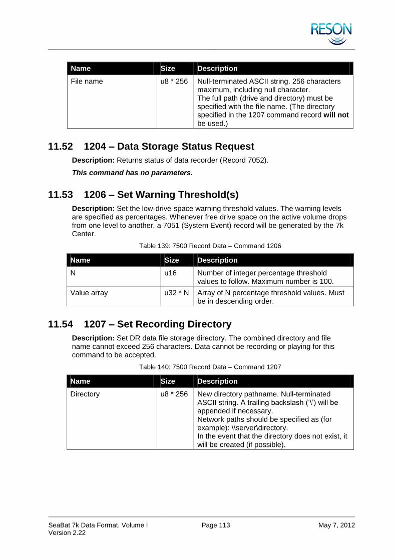
SeaBat 7k Data Format, Volume I Version 2.22
Page 113 May 7, 2012
Name Size Description
File name u8 * 256 Null-terminated ASCII string. 256 characters maximum, including null character. The full path (drive and directory) must be specified with the file name. (The directory specified in the 1207 command record will not be used.)
11.52 1204 – Data Storage Status Request
Description: Returns status of data recorder (Record 7052).
This command has no parameters.
11.53 1206 – Set Warning Threshold(s)
Description: Set the low-drive-space warning threshold values. The warning levels are specified as percentages. Whenever free drive space on the active volume drops from one level to another, a 7051 (System Event) record will be generated by the 7k Center.
Table 139: 7500 Record Data – Command 1206
Name Size Description
N u16 Number of integer percentage threshold values to follow. Maximum number is 100.
Value array u32 * N Array of N percentage threshold values. Must be in descending order.
11.54 1207 – Set Recording Directory
Description: Set DR data file storage directory. The combined directory and file name cannot exceed 256 characters. Data cannot be recording or playing for this command to be accepted.
Table 140: 7500 Record Data – Command 1207
Name Size Description
Directory u8 * 256 New directory pathname. Null-terminated ASCII string. A trailing backslash (‘\’) will be appended if necessary. Network paths should be specified as (for example): \\server\directory. In the event that the directory does not exist, it will be created (if possible).

SeaBat 7k Data Format, Volume I Version 2.22
Page 114 May 7, 2012
11.55 1209 – Set Filtering
Description: Sets playback mode OR record mode filtering. Allows for inclusionary record filtering during playback or recording.
The 7k records available for recording are listed below:
1000 1001 1002 1003 1004 1005 1006 1007 1008 1009
1010 1011 1012 1013 1014 1015 1016 1017 1020 1050
7000 7002 7004 7006 7007 7008 7011 7012 7017 7018
7021 7026 7027 7028 7038 7039 7048 7057 7058 7068
7503 7504 7505 7511 7610 7611 7612 8012
However, since new records are defined from time to time, and others may become obsolete, it is recommended to use the 7052 “recording status” record, which is available as a single record request or via subscription, in order to obtain the list of records supported by your version of the software. The 7052 record will contain the complete list of available records if the “Filter Method” field of the most recent 1209 command record is set to 0 (No filtering).
The minimal record set should include 7000, 7004, and either 7011 + 7006 (bathymetry) or 7018 (FLS). Full reprocessing of .s7k files requires water column data record 7018 or 7008 (obsolete). The SeaBat UI enforces this minimal set via the 1209 command records it sends to the 7k Center.
Table 141: 7500 Record Data – Command 1209
Name Size Description
Filter type u16 0 – By record
Filter method u16 0 – None, all records will be included
1 – Inclusionary, ‘Filter List’ is the list of records for playback or recording
N u16 Number of record IDs in ‘Filter List’ (maximum 128)
Filter list u32 * N List of N record IDs for filtering to act upon
11.56 1400 – Autopilot Table Update
Description: Autopilot table to be loaded.
Table 142: 7500 Record Data – Command 1400
Name Size Description
Size i32 Table size
Version i32 Table version: currently set at 3
Mode u32 0 – Range based
1 – Depth based
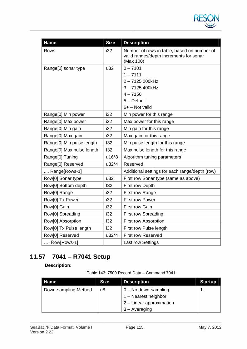
SeaBat 7k Data Format, Volume I Version 2.22
Page 115 May 7, 2012
Name Size Description
Rows i32 Number of rows in table, based on number of valid ranges/depth increments for sonar (Max 100)
Range[0] sonar type u32 0 – 7101
1 – 7111
2 – 7125 200kHz
3 – 7125 400kHz
4 – 7150
5 – Default
6+ – Not valid
Range[0] Min power i32 Min power for this range
Range[0] Max power i32 Max power for this range
Range[0] Min gain i32 Min gain for this range
Range[0] Max gain i32 Max gain for this range
Range[0] Min pulse length f32 Min pulse length for this range
Range[0] Max pulse length f32 Max pulse length for this range
Range[0] Tuning u16*8 Algorithm tuning parameters
Range[0] Reserved u32*4 Reserved
.... Range[Rows-1] Additional settings for each range/depth (row)
Row[0] Sonar type u32 First row Sonar type (same as above)
Row[0] Bottom depth f32 First row Depth
Row[0] Range i32 First row Range
Row[0] Tx Power i32 First row Power
Row[0] Gain i32 First row Gain
Row[0] Spreading i32 First row Spreading
Row[0] Absorption i32 First row Absorption
Row[0] Tx Pulse length i32 First row Pulse length
Row[0] Reserved u32*4 First row Reserved
…. Row[Rows-1] Last row Settings
11.57 7041 – R7041 Setup
Description:
Table 143: 7500 Record Data – Command 7041
Name Size Description Startup
Down-sampling Method u8 0 – No down-sampling
1 – Nearest neighbor
2 – Linear approximation
3 – Averaging
1

SeaBat 7k Data Format, Volume I Version 2.22
Page 116 May 7, 2012
Name Size Description Startup
Filtering Method u8 0 – No filtering 0
Flags u16 BIT FIELD:
Bit 0-2:
0 – Reduction relative to pulse length
1 – Reduction relative to sample rate
2 – Absolute reduction
3-7 – Reserved
Bit 3:
1 – Discard data beyond absolute gates
Bit 4:
1 – Discard data beyond bottom detection point
Bit 5-6:
0 – Magnitude only
1 – Magnitude and Phase
2 – Calibrated Magnitude
3 – Reserved
Bit 7: Beam identification method
0 – Beam number (u16)
1 – Beam angle (f32, in radians)
Bit 8-15: Reserved (always zero)
0x20
Multiplier/Size f32/u32 For relative reduction, this field contains floating point multiplier value
For absolute reduction this field contains integer number for max samples
1.0
(Calibrated) Magnitude Encoding
u8 Magnitude Encoding Methods:
0 – 16 bit values
1 – 8 bit ½dB
2+ – Reserved
Calibrated Magnitude Encoding Methods:
0+ – Reserved
Phase Encoding u8 Phase Encoding Methods:
0+ – Reserved

SeaBat 7k Data Format, Volume I Version 2.22
Page 117 May 7, 2012
11.58 7610 – Manual Sound Velocity
Description: Set SVP filtering manual sound velocity value, with optional ‘override’ flag. If override flag is set, then 7610 records received by the 7K Center from other clients (e.g. PDS2000) will be ignored.
Table 144: 7500 Record Data – Command 7610
Name Size Description
Flags w16 BIT FIELD:
Bit 0: Manual Override
If set any subsequent 7610 record will be ignored, otherwise any subsequent 7610 record will change the Sound Velocity value
Bit 1: Settings Only
If set the Sound Velocity value will not be updated and Sound Velocity field within this remote command will be ignored
Bit 2: Filter Setting
If set SVP Filter type will be changed, otherwise SVP Filter field within this remote command will be ignored
Bit 3-15: Reserved, must be zeros
Sound velocity f32 Sound velocity in m/s
SVP Filter u8 SVP Filter type
1 – No Filter
2 – Light Filter
3 – Normal Filter
4 – SVP70 Wizard
NOTE: to change the filter values Flags Bit 2 must be set
Reserved u8*3 Reserved

SeaBat 7k Data Format, Volume I Version 2.22
Page 118 May 7, 2012
APPENDIX A PDS2000 OPTIONAL DATA
The following tables show optional data that may be sent for compatibility with PDS2000.
DRF RTH RD OD DRF
Table 145: 7006 – Optional Data
Name Size Description
Frequency f32 Ping Frequency in Hz
Latitude f64 Latitude of vessel reference point in radians
-/2 to /2, south negative
Longitude f64 Longitude of vessel reference point in radians
- to , west negative
Heading f32 Heading of vessel at transmit time in radians
Height source u8 Method used to correct to chart datum. If height source = 1, then Tide = ‘0’.
0 – None
1 – RTK
2 – Tide
Tide f32 In meters
Roll f32 Roll (in radians) at transmit time
Pitch f32 Pitch (in radians) at transmit time
Heave f32 Heave (in radians) at transmit time
Vehicle depth f32 Vehicle depth at transmit time in meters
The following set of data items are repeated for each beam:
Beam 0 – Depth f32 Depth relative chart datum (or relative waterline if Height source = 0) (in meters)
Beam 0 – Along track distance
f32 Along track distance in vessel grid (in meters)
Beam 0 – Across track distance
f32 Across track distance in vessel grid (in meters)
Beam 0 – Pointing angle f32 Beam pointing angle from vertical in radians
Beam 0 – Azimuth angle f32 Beam azimuth angle in radians
Table 146: 7007 – Optional Data
Name Size Description
Frequency f32 Ping Frequency in Hz
Latitude f64 Latitude of vessel reference point in radians
-/2 to /2, south negative

SeaBat 7k Data Format, Volume I Version 2.22
Page 119 May 7, 2012
Longitude f64 Longitude of vessel reference point in radians
- to , west negative
Heading f32 Heading of vessel at transmit time in radians
Depth f32 Depth for slant range correction in meters
Table 147: 7008 – Optional Data
Name Size Description
Frequency f32 Ping Frequency in Hz
Latitude f64 Latitude of vessel reference point in Radians
-/2 to /2, south negative
Longitude f64 Longitude of vessel reference point in radians
- to , west negative
Heading f32 Heading of vessel at transmit time in radians
Following set of data items is repeated for each beam:
Beam – Along track distance
f32 Along track distance in vessel grid in meters
Beam – Across track distance
f32 Across track distance in vessel grid in meters
Center sample number u32 Sample number at detection point of beam
Table 148: 7027 – Optional Data
Name Size Description
Frequency f32 Ping Frequency in Hz
Latitude f64 Latitude of vessel reference point in radians
-/2 to /2, south negative
Longitude f64 Longitude of vessel reference point in radians
- to , west negative
Heading f32 Heading of vessel at transmit time in radians
Height source u8 Method used to correct to chart datum. If height source = 1, then Tide = ‘0’.
0 – None
1 – RTK
2 – Tide
Tide f32 In meters
Roll f32 Roll (in radians) at transmit time
Pitch f32 Pitch (in radians) at transmit time
Heave f32 Heave (in radians) at transmit time
Vehicle depth f32 Vehicle depth at transmit time in meters
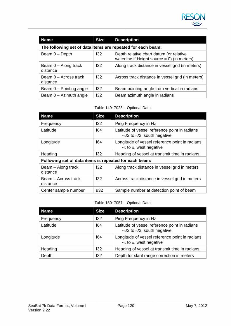
SeaBat 7k Data Format, Volume I Version 2.22
Page 120 May 7, 2012
Name Size Description
The following set of data items are repeated for each beam:
Beam 0 – Depth f32 Depth relative chart datum (or relative waterline if Height source = 0) (in meters)
Beam 0 – Along track distance
f32 Along track distance in vessel grid (in meters)
Beam 0 – Across track distance
f32 Across track distance in vessel grid (in meters)
Beam 0 – Pointing angle f32 Beam pointing angle from vertical in radians
Beam 0 – Azimuth angle f32 Beam azimuth angle in radians
Table 149: 7028 – Optional Data
Name Size Description
Frequency f32 Ping Frequency in Hz
Latitude f64 Latitude of vessel reference point in radians
-/2 to /2, south negative
Longitude f64 Longitude of vessel reference point in radians
- to , west negative
Heading f32 Heading of vessel at transmit time in radians
Following set of data items is repeated for each beam:
Beam – Along track distance
f32 Along track distance in vessel grid in meters
Beam – Across track distance
f32 Across track distance in vessel grid in meters
Center sample number u32 Sample number at detection point of beam
Table 150: 7057 – Optional Data
Name Size Description
Frequency f32 Ping Frequency in Hz
Latitude f64 Latitude of vessel reference point in radians
-/2 to /2, south negative
Longitude f64 Longitude of vessel reference point in radians
- to , west negative
Heading f32 Heading of vessel at transmit time in radians
Depth f32 Depth for slant range correction in meters
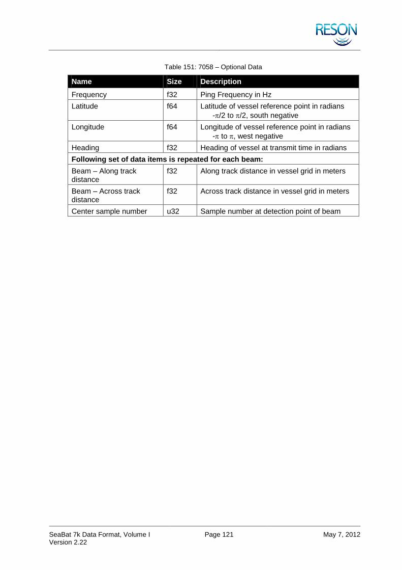
SeaBat 7k Data Format, Volume I Version 2.22
Page 121 May 7, 2012
Table 151: 7058 – Optional Data
Name Size Description
Frequency f32 Ping Frequency in Hz
Latitude f64 Latitude of vessel reference point in radians
-/2 to /2, south negative
Longitude f64 Longitude of vessel reference point in radians
- to , west negative
Heading f32 Heading of vessel at transmit time in radians
Following set of data items is repeated for each beam:
Beam – Along track distance
f32 Along track distance in vessel grid in meters
Beam – Across track distance
f32 Across track distance in vessel grid in meters
Center sample number u32 Sample number at detection point of beam

SeaBat 7k Data Format, Volume I Version 2.22
Page 122 May 7, 2012
APPENDIX B DEVICE IDENTIFIERS
The Data Record Frame (see Table 5: Data Record Frame) requires a Device Identifier parameter. The table below provides the list of valid Device Identifiers and their descriptions.
Table 152: Device Identifiers
Identifier Vendor Description
100 Generic Position Sensor (e.g., GPS)
101 Generic Heading Sensor (e.g., Gyro)
102 Generic Attitude Sensor
103 Generic MBES
104 Generic Side-scan Sonar
105 Generic Sub-bottom Profiler
1001 TrueTime PCISG
2000 CDC SMCG
2001 CDC SPG
2002 Empire Magnetics YS2000 Rotator
4013 RESON TC4013
6000 RESON DiverDat
7000 RESON 7k Center
7001 RESON 7k User Interface
7003 RESON PDS2000
7012 RESON SeaBat™ 7012
7100 RESON SeaBat™ 7100
7101 RESON SeaBat™ 7101
7102 RESON SeaBat™ 7102
7111 RESON SeaBat™ 7111
7112 RESON SeaBat™ 7112
7123 RESON SeaBat™ 7123
7125 RESON SeaBat™ 7125
7128 RESON SeaBat™ 7128
7150 RESON SeaBat™ 7150
7160 RESON SeaBat™ 7160
8100 RESON SeaBat™ 8100
8101 RESON SeaBat™ 8101
8102 RESON SeaBat™ 8102
8111 RESON SeaBat™ 8111

SeaBat 7k Data Format, Volume I Version 2.22
Page 123 May 7, 2012
Identifier Vendor Description
8123 RESON SeaBat™ 8123
8124 RESON SeaBat™ 8124
8125 RESON SeaBat™ 8125
8128 RESON SeaBat™ 8128
8150 RESON SeaBat™ 8150
8160 RESON SeaBat™ 8160
10000 TSS DMS 05
10001 TSS 335B
10002 TSS 332B
10010 SeaBird SeaBird SBE37
10200 Litton Litton 200
11000 EdgeTech FS-DW Sub-bottom Profiler (SBP)
11001 EdgeTech FS-DW Low frequency side-scan sonar (LFSSS)
11002 EdgeTech FS-DW High frequency side-scan sonar (HFSSS)
11100 BlueFin BlueFin vehicle controller
11200 Ifremer Techsas
12000 Simrad Simrad RPT319

SeaBat 7k Data Format, Volume I Version 2.22
Page 124 May 7, 2012
APPENDIX C PROJECTION IDENTIFIERS
The following table defines the reserved values for the custom identifier field of the Geodesy record (record number 1011). Definitions of projection-specific parameters are TBD.
Table 153: Projection Identifiers
Custom Identifier Projection
-1 Not used
0 Universal Transverse Mercator (UTM)
1 Albers Equal-Area Conic
2 Azimuthal Equal Area
3 Azimuthal Equidistant
4 Bonne
5 Cassini
6 Double Stereographic
7 Equal-Area Cylindrical
8 Equidistant Conic
9 Equidistant Cylindrical
10 European Stereographic
11 Gnomic
12 Oblique Mercator (Rectified Skew Orthomorphic – with skew angle parameter)
13 Hotine
14 Hungarian National System (EOV)
15 Hungarian National System (EOV)
16 IMW Polyconic
17 Lambert Conformal Conic (1 parallel)
18 Lambert Conformal Conic (2 parallel)
19 Mercator
20 Miller Cylindrical
21 Mollweide
22 Orthographic
23 Polar Azimuthal
24 Equal Area
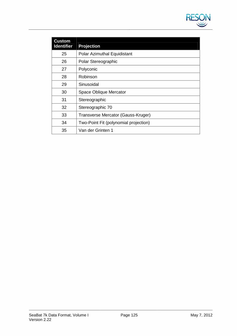
SeaBat 7k Data Format, Volume I Version 2.22
Page 125 May 7, 2012
Custom Identifier Projection
25 Polar Azimuthal Equidistant
26 Polar Stereographic
27 Polyconic
28 Robinson
29 Sinusoidal
30 Space Oblique Mercator
31 Stereographic
32 Stereographic 70
33 Transverse Mercator (Gauss-Kruger)
34 Two-Point Fit (polynomial projection)
35 Van der Grinten 1
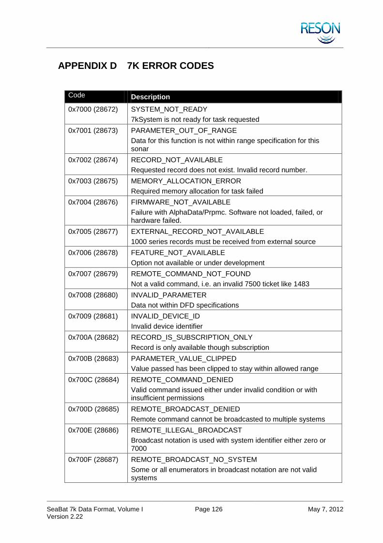
SeaBat 7k Data Format, Volume I Version 2.22
Page 126 May 7, 2012
APPENDIX D 7K ERROR CODES
Code Description
0x7000 (28672) SYSTEM_NOT_READY
7kSystem is not ready for task requested
0x7001 (28673) PARAMETER_OUT_OF_RANGE
Data for this function is not within range specification for this sonar
0x7002 (28674) RECORD_NOT_AVAILABLE
Requested record does not exist. Invalid record number.
0x7003 (28675) MEMORY_ALLOCATION_ERROR
Required memory allocation for task failed
0x7004 (28676) FIRMWARE_NOT_AVAILABLE
Failure with AlphaData/Prpmc. Software not loaded, failed, or hardware failed.
0x7005 (28677) EXTERNAL_RECORD_NOT_AVAILABLE
1000 series records must be received from external source
0x7006 (28678) FEATURE_NOT_AVAILABLE
Option not available or under development
0x7007 (28679) REMOTE_COMMAND_NOT_FOUND
Not a valid command, i.e. an invalid 7500 ticket like 1483
0x7008 (28680) INVALID_PARAMETER
Data not within DFD specifications
0x7009 (28681) INVALID_DEVICE_ID
Invalid device identifier
0x700A (28682) RECORD_IS_SUBSCRIPTION_ONLY
Record is only available though subscription
0x700B (28683) PARAMETER_VALUE_CLIPPED
Value passed has been clipped to stay within allowed range
0x700C (28684) REMOTE_COMMAND_DENIED
Valid command issued either under invalid condition or with insufficient permissions
0x700D (28685) REMOTE_BROADCAST_DENIED
Remote command cannot be broadcasted to multiple systems
0x700E (28686) REMOTE_ILLEGAL_BROADCAST
Broadcast notation is used with system identifier either zero or 7000
0x700F (28687) REMOTE_BROADCAST_NO_SYSTEM
Some or all enumerators in broadcast notation are not valid systems

SeaBat 7k Data Format, Volume I Version 2.22
Page 127 May 7, 2012
Code Description
0x704F (28751) REMOTE_BROADCAST_FAILED
While using RC Broadcast, several systems nacked with different error codes
0x7050 (28752) NETWORK_PROTOCOL_VERSION
Invalid network protocol version
0x7051 (28753) NETWORK_OFFSET
Invalid network offset
0x7052 (28754) DATA_PROTOCOL_VERSION
Record frame protocol version not valid
0x7053 (28755) DATA_SYNC_PATTERN
Record frame sync pattern not valid
0x7054 (28756) DATA_CHECKSUM
Checksum invalid. Data or checksum corrupted.
0x7055 (28757) SYSTEM_EVENT_NOT_LOGGED
Last system event did not get logged
0x7101 (28929) RDR_BUSY
RDR system is already recording or in playback
0x7102 (28930) RDR_STOPPED
RDR is already stopped
0x7103 (28931) RDR_MEMORY_ALLOCATION_ERROR
RDR memory allocation failed
0x7104 (28932) RDR_BUFFER_NULL
RDR allocated a null buffer
0x7105 (28933) RDR_BUFFER_TOO_SMALL
RDR buffer size is smaller than that needed
0x7106 (28934) RDR_NO_FILENAME
File name given to RDR is invalid or no longer exists
0x7107 (28935) RDR_INVALID_PARAMETER
Parameter passed to RDR is not valid
0x7108 (28936) RDR_BAD_RECORDFRAME
RDR data frame header not valid or corrupted
0x7109 (28937) RDR_BAD_CHECKSUM
RDR checksum invalid. Data or checksum corrupted.
0x710A (28938) RDR_BAD_EOF
End of file not reached
0x710B (28939) RDR_FILE_CREATION_FAILED
RDR failed to create new file
0x710C (28940) RDR_FILE_OPEN_FAILED
RDR unable to open requested file

SeaBat 7k Data Format, Volume I Version 2.22
Page 128 May 7, 2012
Code Description
0x710D (28941) RDR_FILE_WRITE_ERROR
RDR unable to write to file
0x710E (28942) RDR_FILE_READ_ERROR
RDR unable to read file
0x710F (28943) RDR_FILE_DELETE_ERROR
RDR unable to delete file
0x7110 (28944) RDR_LOCK_FAILED
System could not lock file for recording/playback
0x7111 (28945) RDR FAILURE
RDR system stopped, thus and future RDR related remote control commands will be rejected
0x7999 (31129) UNKNOWN_ERROR
An unknown error has occurred


![[MS-CSDLBI-Diff]: Conceptual Schema Definition File Format ...MS... · Conceptual Schema Definition File Format with Business ... Conceptual Schema Definition File Format with Business](https://img.dokumen.tips/doc/110x75/5cd72bdf88c993dc268c1c36/ms-csdlbi-diff-conceptual-schema-definition-file-format-ms-conceptual.jpg)


![[MS-CSDLBI]: Conceptual Schema Definition File Format with ...MS... · [MS-CSDLBI]: Conceptual Schema Definition File Format with Business ... ... "Conceptual Schema Definition File](https://img.dokumen.tips/doc/110x75/5cd72bdf88c993dc268c1c35/ms-csdlbi-conceptual-schema-definition-file-format-with-ms-ms-csdlbi.jpg)


![[MS-RDL]: Report Definition Language File Format](https://img.dokumen.tips/doc/110x75/55cf996c550346d0339d5645/ms-rdl-report-definition-language-file-format.jpg)

