Embed Size (px)
Citation preview
DATA COMMUNICATION & NETWORK
KCRI COLLEGE Page 1
Unit 1
DATA COMMUNICATIONS Data communications are the exchange of data between two devices via some form of transmission medium such as a wired or wireless.For data communications to occur, the communicating devices must be part of a communication system made up of combination of hardware and software.The effectiveness of a data communications system depends on four fundamental characteristics: delivery, accuracy and timeliness.
Delivery: The system must deliver data to the correct destination. Data mustbe received by the intended device or user and only by that device or user.
Accuracy: The system must deliver the data accurately. Data that have beenaltered in transmission and left uncorrected are unusable.
Timeliness: The system must deliver data in a timely manner. Datadelivered late are useless. Data delivering in the same order that they are produced, and without significant delay. This kind of delivery is called real-time transmission.
Computer network is defined as a set of interconnected autonomous systems that facilitate distributed processing of information. It results in better performance with high speed of processing. Advantages of Network: These are main advantages of Computer Networks:
1. Central Storage of Data – Files can be stored on a central node (the file server) that can be shared and made available to each and every user in an organization.
2. Anyone can connect to a computer network – There is a negligible range of abilities required to connect to a modern computer network. The effortlessness of joining makes it workable for even youthful kids to start exploiting the data.
3. Faster Problem solving – Since an extensive procedure is disintegrated into a few littler procedures and each is taken care of by all the associated gadgets, an explicit issue can be settled in lesser time.
4. Reliability – Reliability implies backing up of information. Due to some reason equipment crash, and so on, the information gets undermined or inaccessible on one PC, another duplicate of similar information is accessible on another workstation for future use, which prompts smooth working and further handling without interruption.
5. It is highly flexible – This innovation is known to be truly adaptable, as it offers clients the chance to investigate everything about fundamental things, for example, programming without influencing their usefulness.
6. Security through Authorization – Security and protection of information is additionally settled through system. As just the

DATA COMMUNICATION & NETWORK
KCRI COLLEGE Page 2
system clients are approved to get to specific records or applications, no other individual can crack the protection or security of information.
7. It boosts storage capacity – Since you will share data, records and assets to other individuals, you need to guarantee all information and substances are legitimately put away in the framework. With this systems administration innovation, you can do the majority of this with no issue, while having all the space you requirement for capacity.
Disadvantages of Network: These are main disadvantages of Computer Networks:
1. It lacks robustness – If a PC system’s principle server separates, the whole framework would end up futile. Also, if it has a bridging device or a central linking server that fails, the entire network would also come to a standstill. To manage these issues, gigantic systems ought to have a ground-breaking PC to fill in as document server to influence setting to up and keeping up the system less demanding.
2. It lacks independence – PC organizing includes a procedure that is worked utilizing PCs, so individuals will depend a greater amount of PC work, rather than applying an exertion for their jobs that needs to be done. Beside this, they will be subject to the primary document server, which implies that, in the event that it separates, the framework would end up futile, making clients inactive.
3. Virus and Malware – On the off chance that even one PC on a system gets contaminated with an infection, there is a possibility for alternate frameworks to get tainted as well. Infections can spread on a system effectively, in view of the between availability of different gadgets.4. Lack of Independence
4. Cost of network – The expense of executing the system including cabling and equipment can be expensive.
Classification of computer networks Computer network can be classified on the basis of following features: 1) By Scale: Computer networks may be classified according to the scale :
Local Area Network (LAN) Metropolitan Area Network (MAN) Wide Area Network (WAN)
2) By Connection Method: Computer networks can also be classified according to the hardware technology that is used to connect the individual devices in the network such as:
Optical fiber,
Ethernet,
Wireless LAN. 3) By Functional Relationship (Network Architectures): Computer networks may be classified according to the functional relationships which exist between the elements of the network. This classification also called computer architecture. There are two type of network architecture:

DATA COMMUNICATION & NETWORK
KCRI COLLEGE Page 3
Client-Server Peer-to-Peer Architecture
4) By Network Topology: Network Topology signifies the way in which intelligent devices in the network see their logical or physical relations to one another. Computer networks may be classified according to the network topology upon which the network is based, such as:
Bus Network Star Network Ring Network Mesh Network Star-Bus Network Tree or Hierarchical Topology Network
Computer Network Architecture Computer Network Architecture is defined as the physical and logical design of the software, hardware, protocols, and media of the transmission of data. Simply we can say that how computers are organized and how tasks are allocated to the computer. The two types of network architectures are used:
Peer-To-Peer network
o Peer-To-Peer network is a network in which all the computers are linked together with equal privilege and responsibilities for processing the data.
o Peer-To-Peer network is useful for small environments, usually up to 10 computers. o Peer-To-Peer network has no dedicated server. o Special permissions are assigned to each computer for sharing the resources, but this
can lead to a problem if the computer with the resource is down.

DATA COMMUNICATION & NETWORK
KCRI COLLEGE Page 4
Advantages of Peer-To-Peer Network: o It is less costly as it does not contain any dedicated server. o If one computer stops working but, other computers will not stop working. o It is easy to set up and maintain as each computer manages itself.
Disadvantages of Peer-To-Peer Network: o In the case of Peer-To-Peer network, it does not contain the centralized system.
Therefore, it cannot back up the data as the data is different in different locations. o It has a security issue as the device is managed itself.
Client/Server Network
o Client/Server network is a network model designed for the end users called clients, to access the resources such as songs, video, etc. from a central computer known as Server.
o The central controller is known as a server while all other computers in the network are called clients.
o A server performs all the major operations such as security and network management. o A server is responsible for managing all the resources such as files, directories, printer,
etc. o All the clients communicate with each other through a server. For example, if client1
wants to send some data to client 2, then it first sends the request to the server for the permission. The server sends the response to the client 1 to initiate its communication with the client 2.
Advantages of Client/Server network:
o A Client/Server network contains the centralized system. Therefore we can back up the data easily.
o A Client/Server network has a dedicated server that improves the overall performance of the whole system.
o Security is better in Client/Server network as a single server administers the shared resources.
o It also increases the speed of the sharing resources.

DATA COMMUNICATION & NETWORK
KCRI COLLEGE Page 5
Disadvantages of Client/Server network: o Client/Server network is expensive as it requires the server with large memory. o A server has a Network Operating System (NOS) to provide the resources to the clients,
but the cost of NOS is very high. o It requires a dedicated network administrator to manage all the resources.
Server & its types A server is a computer or system that provides resources, data, services, or programs to other computers, known as clients, over a network. In theory, whenever computers share resources with client machines they are considered servers. There are many types of servers There are many types of servers that all perform different functions. Many networks contain one or more of the common server types:
File servers File servers store and distribute files. Multiple clients or users may share files stored on a server. In addition, centrally storing files offers easier backup or fault tolerance solutions than attempting to provide security and integrity for files on every device in an organization. File server hardware can be designed to maximize read and write speeds to improve performance.
Print servers Print servers allow for the management and distribution of printing functionality. Rather than attaching a printer to every workstation, a single print server can respond to printing requests from numerous clients. Today, some larger and higher-end printers come with their own built-in print server, which removes the need for an additional computer-based print server. This internal print server also functions by responding to print requests from a client.
Application servers Application servers run applications in lieu of client computers running applications locally. Application servers often run resource-intensive applications that are shared by a large number of users. Doing so removes the need for each client to have sufficient resources to run the applications. It also removes the need to install and maintain software on many machines as opposed to only one.
DNS servers Domain Name System (DNS) servers are application servers that provide name resolution to client computers by converting names easily understood by humans into machine-readable IP addresses. The DNS system is a widely distributed database of names and other DNS servers, each of which can be used to request an otherwise unknown computer name. When a client needs the address of a system, it sends a DNS request with the name of the desired resource to a DNS server. The DNS server responds with the necessary IP address from its table of names.
Mail servers Mail servers are a very common type of application server. Mail servers receive emails sent to a user and store them until requested by a client on behalf of said user. Having an email server allows for a single machine to be properly configured and attached to the network at all times. It is then ready to send and receive messages rather than requiring every client machine to have its own email subsystem continuously running.

DATA COMMUNICATION & NETWORK
KCRI COLLEGE Page 6
Web servers One of the most abundant types of servers in today’s market is a web server. A web server is a special kind of application server that hosts programs and data requested by users across the Internet or an intranet. Web servers respond to requests from browsers running on client computers for web pages, or other web-based services. Common web servers include Apache web servers, Microsoft Internet Information Services (IIS) servers and Nginx servers.
Database servers The amount of data used by companies, users, and other services is staggering. Much of that data is stored in databases. Databases need to be accessible to multiple clients at any given time and can require extraordinary amounts of disk space. Both of these needs lend themselves well to locating such databases on servers. Database servers run database applications and respond to numerous requests from clients. Common database server applications include Oracle, Microsoft SQL Server, DB2, and Informix.
Virtual servers Virtual servers are taking the server world by storm. Unlike traditional servers that are installed as an operating system on machine hardware, virtual servers exist only as defined within specialized software called hypervisor. Each hypervisor can run hundreds, or even thousands, of virtual servers all at once. The hypervisor presents virtual hardware to the server as if it were real physical hardware. The virtual server uses the virtual hardware as usual, and the hypervisor passes the actual computation and storage needs onto the real hardware beneath, which is shared among all the other virtual servers.
Proxy servers A proxy server acts as an intermediary between a client and a server. Often used to isolate either the clients or servers for security purposes, a proxy server takes the request from the client. Instead of responding to the client, it passes the request on to another server or process. The proxy server receives the response from the second server and then replies to the original client as if it were replying on its own. In this way, neither the client nor the responding server needs to directly connect to each other.
Monitoring and management servers Some servers exist to monitor or manage other systems and clients. There are many types of monitoring servers. Several of them listen to the network and receive every client request and server response, but some do not request or respond to data themselves. In this way, the monitoring server can keep track of all the traffic on the network, as well as the requests and replies of clients and servers, without interfering with those operations. A monitoring server will respond to requests from monitoring clients such as those run by network administrators watching the health of the network. Wired and Wireless Transmission
Wired Network In computing terminology, the term "wired" is used to differentiate between wireless connections and those that involve cables. A wired setup uses physical cables to transfer data between different devices and computer systems. The cables can be copper wire, twisted pair or fiber optic. Wired network is used to carry different forms of electrical signals from one end

DATA COMMUNICATION & NETWORK
KCRI COLLEGE Page 7
to the other. Most wired networks use Ethernet cables to transfer data between connected PCs. Ethernet works or operate in a narrow range and it is little bit difficult to configure as compared to wireless networking technologies.
Wireless Network Wireless network refers to the use of infrared or radio frequency signals to share information and resources between devices. Wireless technologies are designed to reduce the time and different type of obstacles created by the cables. Wireless network does not use wires for data or voice communication; it uses radio frequency waves as mentioned above. Many types of wireless devices are available today; for example, cellular mobile, handheld PCs, satellite receivers, laptop, PDAs, wireless sensors etc. Below table mention comparison between wired network and wireless network:-
Sr. No Parameters Wired Network Wireless Network
1 Installation Difficult (Because more no’s of compound are used during installation and required no’s of cables for connecting each and every computers)
Easy installation
2 Speed and Bandwidth High (up to 100mbps) Low (up to 54mbps)
3 Reliability High(Due to existence of wired technology and as manufactured cable have higher performance)
Reasonably high( because if the major section like router break down the whole network will be affected)
4 Cables Ethernet, copper and optical fibers Works on radio waves and microwaves
5 Mobility Limited, as it operates in the area covered by connected systems with the wired network
Not limited, as it operates in the entire wireless network coverage
6 Security Good Weak
7 Interference Less (Networks are invisible to other wired networks. The presence of one wired network has no effect on the performance of another wired network)
Higher (the potential for radio interference due to weather, other wireless devices, or obstructions like walls)
8 Quality of Service Better Poor
9 Connection setup time
Less More
10 Devices used Hubs and Switches Routers
11 Cost Less as cables are not expensive More as wireless subscriber stations, wireless routers, wireless access points and adapters are expensive
12 Applications LAN (Ethernet), MAN WLAN, WPAN(Zigbee, bluetooth), Infrared,

DATA COMMUNICATION & NETWORK
KCRI COLLEGE Page 8
Sr. No Parameters Wired Network Wireless Network
Cellular(GSM,CDMA, LTE)
13 Standards IEEE802.3 IEEE802.11a, IEEE 802.11b , IEEE802.11g
Baseband and Broadband Transmission
Baseband transmission uses whole frequency spectrum of the medium for the transmission. That is the reason frequency division multiplexing cannot be used in the transmission but time division multiplexing is used in this transmission as in TDM the link is not divided into multiple channels instead it provides each input signal with a time slot, in which the signal utilize whole bandwidth for a given time slot. The signals are carried by wires in the form of electrical pulse. Signals transmitted at point propagated in both the directions hence it is bidirectional. The expansion of baseband signal is limited to shorter distances because at high frequency the attenuation of the signal is most strong and the pulse blur out, causing the large distance communication completely impractical.
Broadband transmission employs analog signals which include optical or electromagnetic wave form of signal. The signals are sent into multiple frequencies permitting multiple signals to be sent simultaneously. Frequency division multiplexing is possible in which the frequency spectrum is divided into multiple sections of bandwidth. The distinct channels can support different types of signals of varying frequency ranges to travel simultaneously (at the same instance). The signals propagated at any point are unidirectional in nature, in simple words the signal can be travelled at only one direction, unlike baseband transmission. It requires two data path that are connected at a point in the network refer to as headend. The first path is used for signal transmission from the station to the headend. And the other path is used for receiving propagated signals.
Comparison Chart
BASIS FOR COMPARISON
BASEBAND TRANSMISSION BROADBAND TRANSMISSION
Type of signaling used
Digital Analog
Application Work well with bus topology. Used with a bus as well as tree topology.
Encoding Used Manchester and Differential Manchester encoding.
PSK encoding.
Transmission Bidirectional Unidirectional
Signal range Signals can be travelled over short distances
Signals can be travelled over long distances without being attenuated.
Layered Technology In layered architecture of Network Model, one whole network process is divided into small tasks. Each small task is then assigned to a particular layer which works dedicatedly to process the task only. Every layer does only specific work.

DATA COMMUNICATION & NETWORK
KCRI COLLEGE Page 9
In layered communication system, one layer of a host deals with the task done by or to be done by its peer layer at the same level on the remote host. The task is either initiated by layer at the lowest level or at the top most level. If the task is initiated by the-top most layers, it is passed on to the layer below it for further processing. The lower layer does the same thing; it processes the task and passes on to lower layer. If the task is initiated by lower most layers, then the reverse path is taken.
Every layer clubs together all procedures, protocols, and methods which it requires to execute its piece of task. All layers identify their counterparts by means of encapsulation header and tail. Overview of OSI Model Open System Interconnect is an open standard for all communication systems. OSI model is established by International Standard Organization (ISO). This model has seven layers:

DATA COMMUNICATION & NETWORK
KCRI COLLEGE Page 10
Application Layer: This layer is responsible for providing interface to the application user. This layer encompasses protocols which directly interact with the user.
Presentation Layer: This layer defines how data in the native format of remote host should be presented in the native format of host.
Session Layer: This layer maintains sessions between remote hosts. For example, once user/password authentication is done, the remote host maintains this session for a while and does not ask for authentication again in that time span.
Transport Layer: This layer is responsible for end-to-end delivery between hosts.
Network Layer: This layer is responsible for address assignment and uniquely addressing hosts in a network.
Data Link Layer: This layer is responsible for reading and writing data from and onto the line. Link errors are detected at this layer.
Physical Layer: This layer defines the hardware, cabling wiring, power output, pulse rate etc.

DATA COMMUNICATION & NETWORK
KCRI COLLEGE Page 11
Unit 2 Types of Transmission Media In data communication terminology, a transmission medium is a physical path between the transmitter and the receiver i.e it is the channel through which data is sent from one place to another. Transmission Media is broadly classified into the following types:
1) Guided Media: It is also referred to as Wired or Bounded transmission media. Signals being transmitted are directed and confined in a narrow pathway by using physical links. Features:
High Speed
Secure
Used for comparatively shorter distances There are 3 major types of Guided Media:
I. Twisted Pair Cable – It consists of 2 separately insulated conductor wires wound about each other. Generally, several such pairs are bundled together in a protective sheath. They are the most widely used Transmission Media. Twisted Pair is of two types:
a) Unshielded Twisted Pair (UTP): This type of cable has the ability to block interference and does not depend on a physical shield for this purpose. It is used for telephonic applications. Advantages:
Least expensive
Easy to install
High speed capacity Disadvantages:
Susceptible to external interference
Lower capacity and performance in comparison to STP
Short distance transmission due to attenuation

DATA COMMUNICATION & NETWORK
KCRI COLLEGE Page 12
b) Shielded Twisted Pair (STP): This type of cable consists of a special jacket to block external interference. It is used in fast-data-rate Ethernet and in voice and data channels of telephone lines.
Advantages:
Better performance at a higher data rate in comparison to UTP
Eliminates crosstalk
Comparitively faster
Disadvantages:
Comparitively difficult to install and manufacture
More expensive
Bulky
II. Coaxial Cable – It has an outer plastic covering containing 2 parallel conductors each having a separate insulated protection cover. Coaxial cable transmits information in two modes: Baseband mode(dedicated cable bandwidth) and Broadband mode(cable bandwidth is split into separate ranges). Cable TVs and analog television networks widely use Coaxial cables.
Advantages:
High Bandwidth
Better noise Immunity
Easy to install and expand
Inexpensive
Disadvantages:
Single cable failure can disrupt the entire network
III. Optical Fiber Cable – It uses the concept of reflection of light through a core made up of glass or plastic. The core is surrounded by a less dense glass or plastic covering called the cladding. It is used for transmission of large volumes of data.
Advantages:
Increased capacity and bandwidth
Light weight
Less signal attenuation
Immunity to electromagnetic interference
Resistance to corrosive materials
Disadvantages:
Difficult to install and maintain
High cost
Fragile
unidirectional, ie, will need another fibre, if we need bidirectional communication

DATA COMMUNICATION & NETWORK
KCRI COLLEGE Page 13
2) Unguided Media: It is also referred to as Wireless or unbounded transmission media. No physical medium is required for the transmission of electromagnetic signals. Features:
Signal is broadcasted through air
Less Secure
Used for larger distances
There are 3 major types of Unguided Media: I. Radio waves –
These are easy to generate and can penetrate through buildings. The sending and receiving antennas need not be aligned. Frequency Range:3KHz – 1GHz. AM and FM radios and cordless phones use Radiowaves for transmission. Further Categorized as
a) Terrestrial b) Satellite.
II. Microwaves – It is a line of sight transmission i.e. the sending and receiving antennas need to be properly aligned with each other. The distance covered by the signal is directly proportional to the height of the antenna. Frequency Range:1GHz – 300GHz. These are majorly used for mobile phone communication and television distribution. III. Infrared –
Infrared waves are used for very short distance communication. They cannot penetrate through obstacles. This prevents interference between systems. Frequency Range:300GHz – 400THz. It is used in TV remotes, wireless mouse, keyboard, printer, etc. Types of Network Topology The arrangement of a network which comprises of nodes and connecting lines via sender and receiver is referred as network topology. The various network topologies are : a) Mesh Topology : In mesh topology, every device is connected to another device via particular channel.
Figure: Every device is connected with another via dedicated channels. These channels are known as links.

DATA COMMUNICATION & NETWORK
KCRI COLLEGE Page 14
If suppose, N number of devices are connected with each other in mesh topology, then
total number of ports that is required by each device is N-1. In the Figure 1, there are 5 devices connected to each other, hence total number of ports required is 4.
If suppose, N number of devices are connected with each other in mesh topology, then total number of dedicated links required to connect them is NC2 i.e. N(N-1)/2. In the Figure 1, there are 5 devices connected to each other, hence total number of links required is 5*4/2 = 10.
Advantages of this topology: It is robust. Fault is diagnosed easily. Data is reliable because data is transferred among the devices
through dedicated channels or links. Provides security and privacy.
Problems with this topology : Installation and configuration is difficult. Cost of cables are high as bulk wiring is required, hence suitable for less number of
devices. Cost of maintenance is high.
b) Star Topology : In star topology, all the devices are connected to a single hub through a cable. This hub is the central node and all others nodes are connected to the central node. The hub can be passive in nature i.e. not intelligent hub such as broadcasting devices, at the same time the hub can be intelligent known as active hubs. Active hubs have repeaters in them.
Figure: A star topology having four systems connected to single point of connection i.e. hub. Advantages of this topology :
If N devices are connected to each other in star topology, then the number of cables required to connect them is N. So, it is easy to set up.
Each device require only 1 port i.e. to connect to the hub. Problems with this topology : If the concentrator (hub) on which the whole topology relies fails, the whole system will
crash down.

DATA COMMUNICATION & NETWORK
KCRI COLLEGE Page 15
Cost of installation is high. Performance is based on the single concentrator i.e. hub.
c) Bus Topology : Bus topology is a network type in which every computer and network device is connected to single cable. It transmits the data from one end to another in single direction. No bi-directional feature is in bus topology.
Figure 3 : A bus topology with shared backbone cable. The nodes are connected to the channel via droop lines. Advantages of this topology : If N devices are connected to each other in bus topology, then the number of cables
required to connect them is 1 which is known as backbone cable and N drop lines are required.
Cost of the cable is less as compared to other topology, but it is used to built small networks.
Problems with this topology : If the common cable fails, then the whole system will crash down. If the network traffic is heavy, it increases collisions in the network. To avoid this, various
protocols are used in MAC layer known as Pure Aloha, Slotted Aloha, CSMA/CD etc.
d) Ring Topology : In this topology, it forms a ring connecting a devices with its exactly two neighbouring devices.
DATA COMMUNICATION & NETWORK
KCRI COLLEGE Page 16
Figure 4 : A ring topology comprises of 4 stations connected with each forming a ring.. The following operations takes place in ring topology are :
1. One station is known as monitor station which takes all the responsibility to perform the operations.
2. To transmit the data, station has to hold the token. After the transmission is done, the token is to be released for other stations to use.
3. When no station is transmitting the data, then the token will circulate in the ring. 4. There are two types of token release techniques : Early token release releases the token
just after the transmitting the data and Delay token release releases the token after the acknowledgement is received from the receiver.
Advantages of this topology : The possibility of collision is minimum in this type of topology. Cheap to install and expand.
Problems with this topology : Troubleshooting is difficult in this topology. Addition of stations in between or removal of stations can disturb the whole topology.
e) Hybrid Topology : This topology is a collection of two or more topologies which are described above. This is a scalable topology which can be expanded easily. It is reliable one but at the same it is a costly topology.

DATA COMMUNICATION & NETWORK
KCRI COLLEGE Page 17
.Network Interface Card A network interface card (NIC) is a hardware component without which a computer cannot be connected over a network. It is a circuit board installed in a computer that provides a dedicated network connection to the computer. It is also called network interface controller, network adapter or LAN adapter. Purpose
NIC allows both wired and wireless communications. NIC allows communications between computers connected via local area network (LAN)
as well as communications over large-scale network through Internet Protocol (IP). NIC is both a physical layer and a data link layer device, i.e. it provides the necessary
hardware circuitry so that the physical layer processes and some data link layer processes can run on it.
Types of NIC Cards NIC cards are of two types −
Internal Network Cards

DATA COMMUNICATION & NETWORK
KCRI COLLEGE Page 18
In internal networks cards, motherboard has a slot for the network card where it can be inserted. It requires network cables to provide network access. Internal network cards are of two types. The first type uses Peripheral Component Interconnect (PCI) connection, while the second type uses Industry Standard Architecture (ISA).
External Network Cards
In desktops and laptops that do not have an internal NIC, external NICs are used. External network cards are of two types: Wireless and USB based. Wireless network card needs to be inserted into the motherboard, however no network cable is required to connect to the network. They are useful while traveling or accessing a wireless signal.

DATA COMMUNICATION & NETWORK
KCRI COLLEGE Page 19
Unit 3 OSI Model OSI stands for Open Systems Interconnection. It has been developed by ISO – ‘International Organization of Standardization‘, in the year 1984. It is a 7 layer architecture with each layer having specific functionality to perform. All these 7 layers work collaboratively to transmit the data from one person to another across the globe.
1. Physical Layer (Layer 1): The lowest layer of the OSI reference model is the physical layer. It is responsible for the actual physical connection between the devices. The physical layer contains information in the form of bits. It is responsible for transmitting individual bits from one node to the next. When receiving data, this layer will get the signal received and convert it into 0s and 1s and send them to the Data Link layer, which will put the frame back together.
The functions of the physical layer are : Bit synchronization: The physical layer provides the synchronization of the bits by
providing a clock. This clock controls both sender and receiver thus providing synchronization at bit level.
Bit rate control: The Physical layer also defines the transmission rate i.e. the number of bits sent per second.
Physical topologies: Physical layer specifies the way in which the different, devices/nodes are arranged in a network i.e. bus, star or mesh topolgy.
Transmission mode: Physical layer also defines the way in which the data flows between the two connected devices. The various transmission modes possible are: Simplex, half-duplex and full-duplex.
DATA COMMUNICATION & NETWORK
KCRI COLLEGE Page 20
2. Data Link Layer (DLL) (Layer 2) : The data link layer is responsible for the node to node delivery of the message. The main function of this layer is to make sure data transfer is error-free from one node to another, over the physical layer. When a packet arrives in a network, it is the responsibility of DLL to transmit it to the Host using its MAC address.
Data Link Layer is divided into two sub layers : a) Logical Link Control (LLC) b) Media Access Control (MAC)
The packet received from Network layer is further divided into frames depending on the frame size of NIC(Network Interface Card). DLL also encapsulates Sender and Receiver’s MAC address in the header. The Receiver’s MAC address is obtained by placing an ARP(Address Resolution Protocol) request onto the wire asking “Who has that IP address?” and the destination host will reply with its MAC address. The functions of the data Link layer are : Framing: Framing is a function of the data link layer. It provides a way for a sender to
transmit a set of bits that are meaningful to the receiver. This can be accomplished by attaching special bit patterns to the beginning and end of the frame.
Physical addressing: After creating frames, Data link layer adds physical addresses (MAC address) of sender and/or receiver in the header of each frame.
Error control: Data link layer provides the mechanism of error control in which it detects and retransmits damaged or lost frames.
Flow Control: The data rate must be constant on both sides else the data may get corrupted thus, flow control coordinates that amount of data that can be sent before receiving acknowledgement.
Access control: When a single communication channel is shared by multiple devices, MAC sub-layer of data link layer helps to determine which device has control over the channel at a given time.
3. Network Layer (Layer 3): Network layer works for the transmission of data from one host to the other located in different networks. It also takes care of packet routing i.e. selection of the shortest path to transmit the packet, from the number of routes available. The sender & receiver’s IP address are placed in the header by the network layer. The functions of the Network layer are: Routing: The network layer protocols determine which route is suitable from source to
destination. This function of network layer is known as routing. Logical Addressing: In order to identify each device on internetwork uniquely, network
layer defines an addressing scheme. The sender & receiver’s IP address are placed in the header by network layer. Such an address distinguishes each device uniquely and universally.
4. Transport Layer (Layer 4) : Transport layer provides services to application layer and takes services from network layer. The data in the transport layer is referred to as Segments. It is responsible for the End to End

DATA COMMUNICATION & NETWORK
KCRI COLLEGE Page 21
Delivery of the complete message. The transport layer also provides the acknowledgement of the successful data transmission and re-transmits the data if an error is found. The functions of the transport layer are : Segmentation and Reassembly: This layer accepts the message from the (session) layer ,
breaks the message into smaller units . Each of the segment produced has a header associated with it. The transport layer at the destination station reassembles the message.
Service Point Addressing: In order to deliver the message to correct process, transport layer header includes a type of address called service point address or port address. Thus by specifying this address, transport layer makes sure that the message is delivered to the correct process.
The services provided by the transport layer : Connection Oriented Service: It is a three-phase process which include
– Connection Establishment – Data Transfer – Termination / disconnection In this type of transmission, the receiving device sends an acknowledgement, back to the source after a packet or group of packet is received. This type of transmission is reliable and secure.
Connection less service: It is a one-phase process and includes Data Transfer. In this type of transmission, the receiver does not acknowledge receipt of a packet. This approach allows for much faster communication between devices. Connection-oriented service is more reliable than connectionless Service.
5. Session Layer (Layer 5): This layer is responsible for establishment of connection, maintenance of sessions, authentication and also ensures security. The functions of the session layer are : Session establishment, maintenance and termination: The layer allows the two
processes to establish, use and terminate a connection. Synchronization : This layer allows a process to add checkpoints which are considered as
synchronization points into the data. These synchronization point help to identify the error so that the data is re-synchronized properly, and ends of the messages are not cut prematurely and data loss is avoided.
Dialog Controller : The session layer allows two systems to start communication with each other in half-duplex or full-duplex.
6. Presentation Layer (Layer 6): Presentation layer is also called the Translation layer. The data from the application layer is extracted here and manipulated as per the required format to transmit over the network. The functions of the presentation layer are: Translation : For example, ASCII to EBCDIC. Encryption/ Decryption : Data encryption translates the data into another form or code.
The encrypted data is known as the cipher text and the decrypted data is known as plain text. A key value is used for encrypting as well as decrypting data.
Compression: Reduces the number of bits that need to be transmitted on the network.

DATA COMMUNICATION & NETWORK
KCRI COLLEGE Page 22
7. Application Layer (Layer 7): At the very top of the OSI Reference Model stack of layers, we find Application layer which is implemented by the network applications. These applications produce the data, which has to be transferred over the network. This layer also serves as a window for the application services
to access the network and for displaying the received information to the user.
Ex: Application – Browsers, Skype Messenger etc. The functions of the Application layer are : Network Virtual Terminal FTAM-File transfer access and management Mail Services Directory Services
OSI model acts as a reference model and is not implemented in the Internet because of its late invention. Current model being used is the TCP/IP model.
Introduction to IEEE 802 Standards IEEE 802 is a family of IEEE standards dealing with local area networks and metropolitan area networks. The IEEE 802 standards are restricted to networks carrying variable-size packets, unlike cell relay networks, for example, where data is transmitted in short, and uniformly sized units called cells. Isochronous networks, where data is transmitted as a steady stream of octets, or groups of octets, at regular time intervals, are also beyond the scope of the IEEE 802 standards. The number “802” has no particular significance: it was simply the next available number IEEE could assign to the standards project,[1] although "802" is sometimes associated with February 1980, the date of the first meeting. The services and protocols specified in IEEE 802 map to the lower two layers (Data Link and Physical) of the seven-layer OSI networking reference model. In fact, IEEE 802 splits the OSI Data Link Layer into two sub-layers named logical link control (LLC) and media access control (MAC), so the layers can be listed like this: Data link layer
o LLC sublayer o MAC sublayer
Physical layer The IEEE 802 family of standards is maintained by the IEEE 802 LAN/MAN Standards Committee (LMSC). The most widely used standards are for the Ethernet family, Token Ring, Wireless LAN (Wi-Fi), Bridging and Virtual Bridged LANs. An individual working group provides the focus for each area. The groups are numbered from 802.1 to 802.12. Ethernet Ethernet is most widely used LAN Technology, which is defined under IEEE standards 802.3. The reason behind its wide usability is Ethernet is easy to understand, implement, maintain and allows low-cost network implementation. Also, Ethernet offers flexibility in terms of topologies which are allowed. Ethernet generally uses Bus Topology. Ethernet operates in two layers of the OSI model, Physical Layer, and Data Link Layer. For Ethernet, the protocol data unit is Frame

DATA COMMUNICATION & NETWORK
KCRI COLLEGE Page 23
since we mainly deal with DLL. In order to handle collision, the Access control mechanism used in Ethernet is CSMA/CD. Ethernet Frame Format Basic frame format which is required for all MAC implementation is defined in IEEE 802.3 standard. Though several optional formats are being used to extend the protocol’s basic capability. Ethernet frame starts with Preamble and SFD, both works at the physical layer. Ethernet header contains both Source and Destination MAC address, after which the payload of the frame is present. The last field is CRC which is used to detect the error. Now, let’s study each field of basic frame format. Ethernet (IEEE 802.3) Frame Format –
PREAMBLE – Ethernet frame starts with 7-Bytes Preamble. This is a pattern of alternative
0’s and 1’s which indicates starting of the frame and allow sender and receiver to establish bit synchronization. Initially, PRE (Preamble) was introduced to allow for the loss of a few bits due to signal delays. But today’s high-speed Ethernet don’t need Preamble to protect the frame bits. PRE (Preamble) indicates the receiver that frame is coming and allow the receiver to lock onto the data stream before the actual frame begins.
Start of frame delimiter (SFD) – This is a 1-Byte field which is always set to 10101011. SFD indicates that upcoming bits are starting of the frame, which is the destination address. Sometimes SFD is considered the part of PRE, this is the reason Preamble is described as 8 Bytes in many places. The SFD warns station or stations that this is the last chance for synchronization.
Destination Address – This is 6-Byte field which contains the MAC address of machine for which data is destined.
Source Address – This is a 6-Byte field which contains the MAC address of source machine. As Source Address is always an individual address (Unicast), the least significant bit of first byte is always 0.
Length – Length is a 2-Byte field, which indicates the length of entire Ethernet frame. This 16-bit field can hold the length value between 0 to 65534, but length cannot be larger than 1500 because of some own limitations of Ethernet.
Data – This is the place where actual data is inserted, also known as Payload. Both IP header and data will be inserted here if Internet Protocol is used over Ethernet. The maximum data present may be as long as 1500 Bytes. In case data length is less than minimum length i.e. 46 bytes, then padding 0’s is added to meet the minimum possible length.

DATA COMMUNICATION & NETWORK
KCRI COLLEGE Page 24
Cyclic Redundancy Check (CRC) – CRC is 4 Byte field. This field contains a 32-bits hash code of data, which is generated over the Destination Address, Source Address, Length, and Data field. If the checksum computed by destination is not the same as sent checksum value, data received is corrupted.
Note – Size of frame of Ethernet IEEE 802.3 varies 64 bytes to 1518 bytes including data length (46 to 1500 bytes). Brief overview on Extended Ethernet Frame (Ethernet II Frame): Standard IEEE 802.3 basic frame format is discussed above in detail. Now let’s see the extended Ethernet frame header, using which we can get Payload even larger than 1500 Bytes.
DA [Destination MAC Address] : 6 bytes SA [Source MAC Address] : 6 bytes Type [0x8870 (Ethertype)] : 2 bytes DSAP [802.2 Destination Service Access Point] : 1 byte SSAP [802.2 Source Service Access Point] : 1 byte Ctrl [802.2 Control Field] : 1 byte Data [Protocol Data] : > 46 bytes FCS [Frame Checksum] : 4 bytes
Although length field is missing in Ethernet II frame, the frame length is known by virtue of the frame being accepted by the network interface. Token Ring Token ring (IEEE 802.5) is a communication protocol in a local area network (LAN) where all stations are connected in a ring topology and pass one or more tokens for channel acquisition. A token is a special frame of 3 bytes that circulates along the ring of stations. A station can send data frames only if it holds a token. The tokens are released on successful receipt of the data frame. Token Passing Mechanism in Token Ring If a station has a frame to transmit when it receives a token, it sends the frame and then passes the token to the next station; otherwise it simply passes the token to the next station.Passing the token means receiving the token from the preceding station and transmitting to the successor station. The data flow is unidirectional in the direction of the token passing. In order that tokens are not circulated infinitely, they are removed from the network once their purpose is completed. This is shown in the following diagram −

DATA COMMUNICATION & NETWORK
KCRI COLLEGE Page 25
Token Ring frame format Topology – Ring topology Transmission – Unidirectional Encoding – Differential Manchester encoding Access control – Token passing Data rates – 4 Mbps, 16 Mbps
Token Ring Frame format:
Start frame delimiter (SFD) – Alerts each station for the arrival of token(or data frame)
or start of the frame. It is used to synchronize clocks.

DATA COMMUNICATION & NETWORK
KCRI COLLEGE Page 26
Access control (AC) –
Priority bits and reservation bits help in implementing priority. Priority bits =
reservation bits = 3. Eg:- server is given priority = 7 and client is given priority = 0. Token bit is used to indicate presence of token frame. If token bit = 1 –> token
frame and if token bit = 0 –> not a token frame. Monitor bit helps in solving orphan packet problem. It is covered by CRC as
monitor are powerful machines which can recalculate CRC when modifying monitor bit. If monitor bit = 1 –> stamped by monitor and if monitor bit = 0 –> not yet stamped by monitor.
Frame control (FC) – First 2 bits indicates whether the frame contains data or control
information. In control frames, this byte specifies the type of control information.
Destination address (DA) and Source address (SA) – consist of two 6-byte fields which is used to indicate MAC address of source and destination.
Data – Data length can vary from 0 to maximum token holding time (THT) according to token reservation strategy adopted. Token ring imposes no lower bound on size of data i.e. an advantage over Ethernet.
Cyclic redundancy check (CRC) – 32 bit CRC which is used to check for errors in the frame, i.e., whether the frame is corrupted or not. If the frame is corrupted, then its discarded.
End delimiter (ED) – It is used to mark the end of frame. In Ethernet, length field is used for this purpose. It also contains bits to indicate a damaged frame and identify the frame that is the last in a logical sequence.
Frame status (FS) – It Is a 1-byte field terminating a data frame.

DATA COMMUNICATION & NETWORK
KCRI COLLEGE Page 27
It makes use of 2 copies of AC bits are used as a error detection mechanism (100% redundancy) as CRC does not cover FS byte so that destination does not have to recalculate CRC when modifying AC bits.
Fiber Distributed Data Interface (FDDI) Fiber Distributed Data Interface (FDDI) is a set of ANSI and ISO standards for transmission of data in local area network (LAN) over fiber optic cables. It is applicable in large LANs that can extend up to 200 kilometers in diameter. Features
FDDI uses optical fiber as its physical medium. It operates in the physical and medium access control (MAC layer) of the Open Systems
Interconnection (OSI) network model. It provides high data rate of 100 Mbps and can support thousands of users. It is used in LANs up to 200 kilometers for long distance voice and multimedia
communication. It uses ring based token passing mechanism and is derived from IEEE 802.4 token bus
standard. It contains two token rings, a primary ring for data and token transmission and a
secondary ring that provides backup if the primary ring fails. FDDI technology can also be used as a backbone for a wide area network (WAN).
The following diagram shows FDDI −

DATA COMMUNICATION & NETWORK
KCRI COLLEGE Page 28
Frame Format The frame format of FDDI is similar to that of token bus as shown in the following diagram −
The fields of an FDDI frame are −
Preamble: 1 byte for synchronization. Start Delimiter: 1 byte that marks the beginning of the frame. Frame Control: 1 byte that specifies whether this is a data frame or control frame. Destination Address: 2-6 bytes that specifies address of destination station. Source Address: 2-6 bytes that specifies address of source station. Payload: A variable length field that carries the data from the network layer. Checksum: 4 bytes frame check sequence for error detection. End Delimiter: 1 byte that marks the end of the frame.
Network Scaling Scalability is an attribute that describes the ability of a process, network, software or organization to grow and manage increased demand. A system, business or software that is described as scalable has an advantage because it is more adaptable to the changing needs or demands of its users or clients. Scalability is often a sign of stability and competitiveness, as it means the network, system, software or organization is ready to handle the influx of demand, increased productivity, and trends, changing needs and even presence or introduction of new competitors. Connectivity Devices 1. Repeater – A repeater operates at the physical layer. Its job is to regenerate the signal over the same network before the signal becomes too weak or corrupted so as to extend the length to which the signal can be transmitted over the same network. An important point to be noted about repeaters is that they do not amplify the signal. When the signal becomes weak, they copy the signal bit by bit and regenerate it at the original strength. It is a 2 port device. 2. Hub – A hub is basically a multiport repeater. A hub connects multiple wires coming from different branches, for example, the connector in star topology which connects different stations. Hubs cannot filter data, so data packets are sent to all connected devices. In other

DATA COMMUNICATION & NETWORK
KCRI COLLEGE Page 29
words, collision domain of all hosts connected through Hub remains one. Also, they do not have intelligence to find out best path for data packets which leads to inefficiencies and wastage. Types of Hub Active Hub:- These are the hubs which have their own power supply and can clean, boost
and relay the signal along with the network. It serves both as a repeater as well as wiring center. These are used to extend the maximum distance between nodes.
Passive Hub: - These are the hubs which collect wiring from nodes and power supply from active hub. These hubs relay signals onto the network without cleaning and boosting them and can’t be used to extend the distance between nodes.
3. Bridge – A bridge operates at data link layer. A bridge is a repeater, with add on the functionality of filtering content by reading the MAC addresses of source and destination. It is also used for interconnecting two LANs working on the same protocol. It has a single input and single output port, thus making it a 2 port device. Types of Bridges
Transparent Bridges:- These are the bridge in which the stations are completely unaware of the bridge’s existence i.e. whether or not a bridge is added or deleted from the network, reconfiguration of the stations is unnecessary. These bridges make use of two processes i.e. bridge forwarding and bridge learning.
Source Routing Bridges:- In these bridges, routing operation is performed by source station and the frame specifies which route to follow. The hot can discover frame by sending a special frame called discovery frame, which spreads through the entire network using all possible paths to destination.
4. Switch – A switch is a multiport bridge with a buffer and a design that can boost its efficiency(a large number of ports imply less traffic) and performance. A switch is a data link layer device. The switch can perform error checking before forwarding data, that makes it very efficient as it does not forward packets that have errors and forward good packets selectively to correct port only. In other words, switch divides collision domain of hosts, but broadcast domain remains same.
5. Routers – A router is a device like a switch that routes data packets based on their IP addresses. Router is mainly a Network Layer device. Routers normally connect LANs and WANs together and have a dynamically updating routing table based on which they make decisions on routing the data packets. Router divide broadcast domains of hosts connected through it.
DATA COMMUNICATION & NETWORK
KCRI COLLEGE Page 30
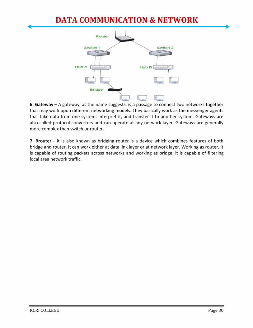
6. Gateway – A gateway, as the name suggests, is a passage to connect two networks together that may work upon different networking models. They basically work as the messenger agents that take data from one system, interpret it, and transfer it to another system. Gateways are also called protocol converters and can operate at any network layer. Gateways are generally more complex than switch or router. 7. Brouter – It is also known as bridging router is a device which combines features of both bridge and router. It can work either at data link layer or at network layer. Working as router, it is capable of routing packets across networks and working as bridge, it is capable of filtering local area network traffic.

DATA COMMUNICATION & NETWORK
KCRI COLLEGE Page 31
Unit 4 The TCP/IP Reference Model TCP/IP means Transmission Control Protocol and Internet Protocol. It is the network model used in the current Internet architecture as well. Protocols are set of rules which govern every possible communication over a network. These protocols describe the movement of data between the source and destination or the internet. They also offer simple naming and addressing schemes.
Protocols and networks in the TCP/IP model:
Overview of TCP/IP reference model TCP/IP that is Transmission Control Protocol and Internet Protocol was developed by Department of Defense’s Project Research Agency (ARPA, later DARPA) as a part of a research project of network interconnection to connect remote machines. The features that stood out during the research, which led to making the TCP/IP reference model were:
Support for a flexible architecture. Adding more machines to a network was easy. The network was robust, and connections remained intact untill the source and
destination machines were functioning.

DATA COMMUNICATION & NETWORK
KCRI COLLEGE Page 32
The overall idea was to allow one application on one computer to talk to(send data packets) another application running on different computer. Different Layers of TCP/IP Reference Model Below we have discussed the 4 layers that form the TCP/IP reference model: Layer 1: Host-to-network Layer
Lowest layer of the all. Protocol is used to connect to the host, so that the packets can be sent over it. Varies from host to host and network to network.
Layer 2: Internet layer Selection of a packet switching network which is based on a connectionless
internetwork layer is called a internet layer. It is the layer which holds the whole architecture together. It helps the packet to travel independently to the destination. Order in which packets are received is different from the way they are sent. IP (Internet Protocol) is used in this layer. The various functions performed by the Internet Layer are: Delivering IP packets Performing routing Avoiding congestion
Layer 3: Transport Layer
It decides if data transmission should be on parallel path or single path.
Functions such as multiplexing, segmenting or splitting on the data is done by transport layer.
The applications can read and write to the transport layer.
Transport layer adds header information to the data.
Transport layer breaks the message (data) into small units so that they are handled more efficiently by the network layer.
Transport layer also arrange the packets to be sent, in sequence. Layer 4: Application Layer
The TCP/IP specifications described a lot of applications that were at the top of the protocol stack. Some of them were TELNET, FTP, SMTP, DNS etc.
TELNET is a two-way communication protocol which allows connecting to a remote machine and run applications on it.
FTP(File Transfer Protocol) is a protocol, that allows File transfer amongst computer users connected over a network. It is reliable, simple and efficient.
SMTP(Simple Mail Transport Protocol) is a protocol, which is used to transport electronic mail between a source and destination, directed via a route.
DNS(Domain Name Server) resolves an IP address into a textual address for Hosts connected over a network.
It allows peer entities to carry conversation.
It defines two end-to-end protocols: TCP and UDP TCP(Transmission Control Protocol): It is a reliable connection-oriented protocol which
handles byte-stream from source to destination without error and flow control.

DATA COMMUNICATION & NETWORK
KCRI COLLEGE Page 33
UDP(User-Datagram Protocol): It is an unreliable connection-less protocol that do not want TCPs, sequencing and flow control. Eg: One-shot request-reply kind of service.
Merits of TCP/IP model 1. It operated independently. 2. It is scalable. 3. Client/server architecture. 4. Supports a number of routing protocols. 5. Can be used to establish a connection between two computers.
Demerits of TCP/IP
1. In this, the transport layer does not guarantee delivery of packets. 2. The model cannot be used in any other application. 3. Replacing protocol is not easy. 4. It has not clearly separated its services, interfaces and protocols.
Internet Protocol (IP)
Internet Protocol is connectionless and unreliable protocol. It ensures no guarantee of successfully transmission of data.
In order to make it reliable, it must be paired with reliable protocol such as TCP at the transport layer.
Internet protocol transmits the data in form of a datagram as shown in the following diagram:
Points to remember:
The length of datagram is variable. The Datagram is divided into two parts: header and data. The length of header is 20 to 60 bytes. The header contains information for routing and delivery of the packet.

DATA COMMUNICATION & NETWORK
KCRI COLLEGE Page 34
Transmission Control Protocol The transmission Control Protocol (TCP) is one of the most important protocols of Internet Protocols suite. It is most widely used protocol for data transmission in communication network such as internet. Features
TCP is reliable protocol. That is, the receiver always sends either positive or negative acknowledgement about the data packet to the sender, so that the sender always has bright clue about whether the data packet is reached the destination or it needs to resend it.
TCP ensures that the data reaches intended destination in the same order it was sent. TCP is connection oriented. TCP requires that connection between two remote points
be established before sending actual data. TCP provides error-checking and recovery mechanism. TCP provides end-to-end communication. TCP provides flow control and quality of service. TCP operates in Client/Server point-to-point mode. TCP provides full duplex server, i.e. it can perform roles of both receiver and sender.
Header The length of TCP header is minimum 20 bytes long and maximum 60 bytes.
Source Port (16-bits) - It identifies source port of the application process on the
sending device. Destination Port (16-bits) - It identifies destination port of the application process on
the receiving device. Sequence Number (32-bits) - Sequence number of data bytes of a segment in a session. Acknowledgement Number (32-bits) - When ACK flag is set, this number contains the
next sequence number of the data byte expected and works as acknowledgement of the previous data received.
Data Offset (4-bits) - This field implies both, the size of TCP header (32-bit words) and the offset of data in current packet in the whole TCP segment.
Reserved (3-bits) - Reserved for future use and all are set zero by default. Flags (1-bit each)
o NS - Nonce Sum bit is used by Explicit Congestion Notification signaling process. o CWR - When a host receives packet with ECE bit set, it sets Congestion Windows
Reduced to acknowledge that ECE received. o ECE -It has two meanings:

DATA COMMUNICATION & NETWORK
KCRI COLLEGE Page 35
If SYN bit is clear to 0, then ECE means that the IP packet has its CE (congestion experience) bit set.
If SYN bit is set to 1, ECE means that the device is ECT capable. o URG - It indicates that Urgent Pointer field has significant data and should be
processed. o ACK - It indicates that Acknowledgement field has significance. If ACK is cleared
to 0, it indicates that packet does not contain any acknowledgement. o PSH - When set, it is a request to the receiving station to PUSH data (as soon as
it comes) to the receiving application without buffering it. o RST - Reset flag has the following features:
It is used to refuse an incoming connection. It is used to reject a segment. It is used to restart a connection.
o SYN - This flag is used to set up a connection between hosts. o FIN - This flag is used to release a connection and no more data is exchanged
thereafter. Because packets with SYN and FIN flags have sequence numbers, they are processed in correct order.
Windows Size - This field is used for flow control between two stations and indicates the amount of buffer (in bytes) the receiver has allocated for a segment, i.e. how much data is the receiver expecting.
Checksum - This field contains the checksum of Header, Data and Pseudo Headers. Urgent Pointer - It points to the urgent data byte if URG flag is set to 1. Options - It facilitates additional options which are not covered by the regular header.
Option field is always described in 32-bit words. If this field contains data less than 32-bit, padding is used to cover the remaining bits to reach 32-bit boundary.
User Datagram Protocol (UDP)
Like IP, UDP is connectionless and unreliable protocol. It doesn’t require making a connection with the host to exchange data. Since UDP is unreliable protocol, there is no mechanism for ensuring that data sent is received.
UDP transmits the data in form of a datagram. The UDP datagram consists of five parts as shown in the following diagram:
Points to remember:
UDP is used by the application that typically transmit small amount of data at one time. UDP provides protocol port used i.e. UDP message contains both source and destination
port number, that makes it possible for UDP software at the destination to deliver the message to correct application program.

DATA COMMUNICATION & NETWORK
KCRI COLLEGE Page 36
Address Resolution Protocol (ARP) Address Resolution Protocol is a communication protocol used for discovering physical address associated with given network address. Typically, ARP is a network layer to data link layer mapping process, which is used to discover MAC address for given Internet Protocol Address. In order to send the data to destination, having IP address is necessary but not sufficient; we also need the physical address of the destination machine. ARP is used to get the physical address (MAC address) of destination machine.
Before sending the IP packet, the MAC address of destination must be known. If not so, then sender broadcasts the ARP-discovery packet requesting the MAC address of intended destination. Since ARP-discovery is broadcast, every host inside that network will get this message but the packet will be discarded by everyone except that intended receiver host whose IP is associated. Now, this receiver will send a unicast packet with its MAC address (ARP-reply) to the sender of ARP-discovery packet. After the original sender receives the ARP-reply, it updates ARP-cache and start sending unicast message to the destination.
Simple Network Management Protocol (SNMP) If an organization has 1000 of devices then to check all devices, one by one every day, are working properly or not is a hectic task. To ease these up, Simple Network Management Protocol (SNMP) is used. Simple Network Management Protocol (SNMP) – SNMP is an application layer protocol which uses UDP port number 161/162.SNMP is used to

DATA COMMUNICATION & NETWORK
KCRI COLLEGE Page 37
monitor the network, detect network faults and sometimes even used to configure remote devices. SNMP components – here are 3 components of SNMP:
1. SNMP Manager – It is a centralised system used to monitor network.It is also known as Network Management Station (NMS)
2. SNMP agent – It is a software management software module installed on a managed device. Managed devices can be network devices like PC, router, switches, servers etc.
3. Management Information Base – MIB consists of information of resources that are to be managed. These information is organised hierarchically. It consists of objects instances which are essentially variables.
SNMP messages – Different variables are:
1. GetRequest– SNMP manager sends this message to request data from SNMP agent. It is simply used to retrieve data from SNMP agent. In response to this, SNMP agent responds with requested value through response message.
2. GetNextRequest– This message can be sent to discover what data is available on a SNMP agent. The SNMP manager can request for data continuously until no more data is left. In this way, SNMP manager can take knowledge of all the available data on SNMP agent.
3. GetBulkRequest– This message is used to retrieve large data at once by the SNMP manager from SNMP agent. It is introduced in SNMPv2c.
4. SetRequest– It is used by SNMP manager to set the value of an object instance on the SNMP agent.
5. Response– It is a message send from agent upon a request from manager. When sent in response to Get messages, it will contain the data requested. When sent in response to Set message, it will contain the newly set value as confirmation that the value has been set.
6. Trap– These are the message send by the agent without being requested by the manager. It is sent when a fault has occurred.
7. InformRequest– It was introduced in SNMPv2c, used to identify if the trap message has been received by the manager or not. The agents can be configured to set trap continuously until it receives an Inform message. It is same as trap but adds an acknowledgement that trap doesn’t provide.

DATA COMMUNICATION & NETWORK
KCRI COLLEGE Page 38
SNMP security levels – It defines the type of security algorithm performed on SNMP packets. These are used in only SNMPv3. There are 3 security levels namely:
1. noAuthNoPriv– This (no authentication, no privacy) security level uses community string for authentication and no encryption for privacy.
2. authNopriv – This security level (authentication, no privacy) uses HMAC with Md5 for authentication and no encryption is used for privacy.
3. authPriv – This security level (authentication, privacy) uses HMAC with Md5 or SHA for authentication and encryption uses DES-56 algorithm.
SNMP versions – There are 3 versions of SNMP:
1. SNMPv1– It uses community strings for authentication and use UDP only.
2. SNMPv2c– It uses community strings for authentication. It uses UDP but can be configured to use TCP.
3. SNMPv3– It uses Hash based MAC with MD5 or SHA for authentication and DES-56 for privacy.This version uses TCP. Therefore, conclusion is the higher the version of SNMP, more secure it will be.
File Transfer protocol (FTP) o FTP stands for File transfer protocol. o FTP is a standard internet protocol provided by TCP/IP used for transmitting the files
from one host to another. o It is mainly used for transferring the web page files from their creator to the computer
that acts as a server for other computers on the internet. o It is also used for downloading the files to computer from other servers.
Objectives of FTP o It provides the sharing of files. o It is used to encourage the use of remote computers. o It transfers the data more reliably and efficiently.
Why FTP? Although transferring files from one system to another is very simple and straightforward, but sometimes it can cause problems. For example, two systems may have different file conventions. Two systems may have different ways to represent text and data. Two systems may have different directory structures. FTP protocol overcomes these problems by establishing two connections between hosts. One connection is used for data transfer, and another connection is used for the control connection.

DATA COMMUNICATION & NETWORK
KCRI COLLEGE Page 39
Mechanism of FTP
The above figure shows the basic model of the FTP. The FTP client has three components: the user interface, control process, and data transfer process. The server has two components: the server control process and the server data transfer process.
There are two types of connections in FTP:
o Control Connection: The control connection uses very simple rules for communication. Through control connection, we can transfer a line of command or line of response at a time. The control connection is made between the control processes. The control connection remains connected during the entire interactive FTP session.
o Data Connection: The Data Connection uses very complex rules as data types may vary. The data connection is made between data transfer processes. The data connection opens when a command comes for transferring the files and closes when the file is transferred.
FTP Clients o FTP client is a program that implements a file transfer protocol which allows you to
transfer files between two hosts on the internet. o It allows a user to connect to a remote host and upload or download the files.

DATA COMMUNICATION & NETWORK
KCRI COLLEGE Page 40
o It has a set of commands that we can use to connect to a host, transfer the files between you and your host and close the connection.
o The FTP program is also available as a built-in component in a Web browser. This GUI based FTP client makes the file transfer very easy and also does not require to remember the FTP commands.
Advantages of FTP: o Speed: One of the biggest advantages of FTP is speed. The FTP is one of the fastest way
to transfer the files from one computer to another computer. o Efficient: It is more efficient as we do not need to complete all the operations to get the
entire file. o Security: To access the FTP server, we need to login with the username and password.
Therefore, we can say that FTP is more secure. o Back & forth movement: FTP allows us to transfer the files back and forth. Suppose you
are a manager of the company, you send some information to all the employees, and they all send information back on the same server.
Disadvantages of FTP: o The standard requirement of the industry is that all the FTP transmissions should be
encrypted. However, not all the FTP providers are equal and not all the providers offer encryption. So, we will have to look out for the FTP providers that provides encryption.
o FTP serves two operations, i.e., to send and receive large files on a network. However, the size limit of the file is 2GB that can be sent. It also doesn't allow you to run simultaneous transfers to multiple receivers.
o Passwords and file contents are sent in clear text that allows unwanted eavesdropping. So, it is quite possible that attackers can carry out the brute force attack by trying to guess the FTP password.
o It is not compatible with every system.
Simple Mail Transfer Protocol (SMTP) o SMTP stands for Simple Mail Transfer Protocol. o SMTP is a set of communication guidelines that allow software to transmit an electronic
mail over the internet is called Simple Mail Transfer Protocol. o It is a program used for sending messages to other computer users based on e-mail
addresses. o It provides a mail exchange between users on the same or different computers, and it
also supports: o It can send a single message to one or more recipients. o Sending message can include text, voice, video or graphics. o It can also send the messages on networks outside the internet.
o The main purpose of SMTP is used to set up communication rules between servers. The servers have a way of identifying themselves and announcing what kind of communication they are trying to perform. They also have a way of handling the errors such as incorrect email address. For example, if the recipient address is wrong, then receiving server reply with an error message of some kind.

DATA COMMUNICATION & NETWORK
KCRI COLLEGE Page 41
Components of SMTP
o First, we will break the SMTP client and SMTP server into two components such as user agent (UA) and mail transfer agent (MTA). The user agent (UA) prepares the message, creates the envelope and then puts the message in the envelope. The mail transfer agent (MTA) transfers this mail across the internet.
o
o SMTP allows a more complex system by adding a relaying system. Instead of just having one MTA at sending side and one at receiving side, more MTAs can be added, acting either as a client or server to relay the email.

DATA COMMUNICATION & NETWORK
KCRI COLLEGE Page 42
o The relaying system without TCP/IP protocol can also be used to send the emails to
users, and this is achieved by the use of the mail gateway. The mail gateway is a relay MTA that can be used to receive an email.
Working of SMTP
1. Composition of Mail: A user sends an e-mail by composing an electronic mail message using a Mail User Agent (MUA). Mail User Agent is a program which is used to send and receive mail. The message contains two parts: body and header. The body is the main part of the message while the header includes information such as the sender and recipient address. The header also includes descriptive information such as the subject of the message. In this case, the message body is like a letter and header is like an envelope that contains the recipient's address.

DATA COMMUNICATION & NETWORK
KCRI COLLEGE Page 43
2. Submission of Mail: After composing an email, the mail client then submits the completed e-mail to the SMTP server by using SMTP on TCP port 25.
3. Delivery of Mail: E-mail addresses contain two parts: username of the recipient and domain name. For example, [email protected], where "vivek" is the username of the recipient and "gmail.com" is the domain name. If the domain name of the recipient's email address is different from the sender's domain name, then MSA will send the mail to the Mail Transfer Agent (MTA). To relay the email, the MTA will find the target domain. It checks the MX record from Domain Name System to obtain the target domain. The MX record contains the domain name and IP address of the recipient's domain. Once the record is located, MTA connects to the exchange server to relay the message.
4. Receipt and Processing of Mail: Once the incoming message is received, the exchange server delivers it to the incoming server (Mail Delivery Agent) which stores the e-mail where it waits for the user to retrieve it.
5. Access and Retrieval of Mail: The stored email in MDA can be retrieved by using MUA (Mail User Agent). MUA can be accessed by using login and password.
Telnet o The main task of the internet is to provide services to users. For example,users want
to run different application programs at the remote site and transfers a result to the local site. This requires a client-server program such as FTP, SMTP. But this would not allow us to create a specific program for each demand.
o The better solution is to provide a general client-server program that lets the user access any application program on a remote computer. Therefore, a program that allows a user to log on to a remote computer. A popular client-server program Telnet is used to meet such demands. Telnet is an abbreviation for Terminal Network.
o Telnet provides a connection to the remote computer in such a way that a local terminal appears to be at the remote side.
There are two types of login: Local Login

DATA COMMUNICATION & NETWORK
KCRI COLLEGE Page 44
o When a user logs into a local computer, then it is known as local login. o When the workstation running terminal emulator, the keystrokes entered by
the user are accepted by the terminal driver. The terminal driver then passes these characters to the operating system which in turn, invokes the desired application program.
o However, the operating system has special meaning to special characters. For example, in UNIX some combination of characters have special meanings such as control character with "z" means suspend. Such situations do not create any problem as the terminal driver knows the meaning of such characters. But, it can cause the problems in remote login.
Remote login
o When the user wants to access an application program on a remote
computer, then the user must perform remote login. How remote login occurs At the local site The user sends the keystrokes to the terminal driver, the characters are then sent to the TELNET client. The TELNET client which in turn, transforms the characters to a universal character set known as network virtual terminal characters and delivers them to the local TCP/IP stack At the remote site The commands in NVT forms are transmitted to the TCP/IP at the remote machine. Here, the characters are delivered to the operating system and then pass to the TELNET server. The TELNET server transforms the characters which can be understandable by a remote computer. However, the characters cannot be directly passed to the operating system as a remote operating system does not receive the characters from the TELNET server. Therefore it requires some piece of software that can accept the characters from the TELNET server. The operating system then passes these characters to the appropriate application program.

DATA COMMUNICATION & NETWORK
KCRI COLLEGE Page 45
Network Virtual Terminal (NVT)
o The network virtual terminal is an interface that defines how data and
commands are sent across the network. o In today's world, systems are heterogeneous. For example, the operating
system accepts a special combination of characters such as end-of-file token running a DOS operating system ctrl+z while the token running a UNIX operating system is ctrl+d.
o TELNET solves this issue by defining a universal interface known as network virtual interface.
o The TELNET client translates the characters that come from the local terminal into NVT form and then delivers them to the network. The Telnet server then translates the data from NVT form into a form which can be understandable by a remote computer.
IP Addressing IP address is an address having information about how to reach a specific host, especially outside the LAN. An IP address is a 32 bit unique address having an address space of 232. Generally, there are two notations in which IP address is written, dotted decimal notation and hexadecimal notation. Dotted Decimal Notation:

DATA COMMUNICATION & NETWORK
KCRI COLLEGE Page 46
Hexadecimal Notation:
Some points to be noted about dotted decimal notation:
1. The value of any segment (byte) is between 0 and 255 (both included). 2. There are no zeroes preceding the value in any segment (054 is wrong, 54 is correct).
Classful Addressing The 32 bit IP address is divided into five sub-classes. These are: Class A Class B Class C Class D Class E
Each of these classes has a valid range of IP addresses. Classes D and E are reserved for multicast and experimental purposes respectively. The order of bits in the first octet determine the classes of IP address. IPv4 address is divided into two parts: Network ID Host ID
The class of IP address is used to determine the bits used for network ID and host ID and the number of total networks and hosts possible in that particular class. Each ISP or network administrator assigns IP address to each device that is connected to its network.

DATA COMMUNICATION & NETWORK
KCRI COLLEGE Page 47
Note: IP addresses are globally managed by Internet Assigned Numbers Authority(IANA) and regional Internet registries(RIR). Note: While finding the total number of host IP addresses, 2 IP addresses are not counted and are therefore, decreased from the total count because the first IP address of any network is the network number and whereas the last IP address is reserved for broadcast IP. Class A: P address belonging to class A are assigned to the networks that contain a large number of hosts. The network ID is 8 bits long. The host ID is 24 bits long.
The higher order bit of the first octet in class A is always set to 0. The remaining 7 bits in first octet are used to determine network ID. The 24 bits of host ID are used to determine the host in any network. The default subnet mask for class A is 255.x.x.x. Therefore, class A has a total of: 2^7-2= 126 network ID(Here 2 address is subracted because 0.0.0.0 and 127.x.y.z are
special address. ) 2^24 – 2 = 16,777,214 host ID
IP addresses belonging to class A ranges from 1.x.x.x – 126.x.x.x
Class B: IP address belonging to class B are assigned to the networks that ranges from medium-sized to large-sized networks. The network ID is 16 bits long. The host ID is 16 bits long.
The higher order bits of the first octet of IP addresses of class B are always set to 10. The remaining 14 bits are used to determine network ID. The 16 bits of host ID is used to determine the host in any network. The default sub-net mask for class B is 255.255.x.x. Class B has a total of: 2^14 = 16384 network address 2^16 – 2 = 65534 host address
IP addresses belonging to class B ranges from 128.0.x.x – 191.255.x.x.

DATA COMMUNICATION & NETWORK
KCRI COLLEGE Page 48
Class C: IP address belonging to class C are assigned to small-sized networks. The network ID is 24 bits long. The host ID is 8 bits long.
The higher order bits of the first octet of IP addresses of class C are always set to 110. The remaining 21 bits are used to determine network ID. The 8 bits of host ID is used to determine the host in any network. The default sub-net mask for class C is 255.255.255.x. Class C has a total of: 2^21 = 2097152 network address 2^8 – 2 = 254 host address
IP addresses belonging to class C ranges from 192.0.0.x – 223.255.255.x.
Class D: IP address belonging to class D are reserved for multi-casting. The higher order bits of the first octet of IP addresses belonging to class D are always set to 1110. The remaining bits are for the address that interested hosts recognize. Class D does not posses any sub-net mask. IP addresses belonging to class D ranges from 224.0.0.0 – 239.255.255.255.
Class E:
IP addresses belonging to class E are reserved for experimental and research purposes. IP addresses of class E ranges from 240.0.0.0 – 255.255.255.254. This class doesn’t have any sub-
net mask. The higher order bits of first octet of class E are always set to 1111.

DATA COMMUNICATION & NETWORK
KCRI COLLEGE Page 49
Range of special IP addresses: 169.254.0.0 – 169.254.0.16 : Link local addresses 127.0.0.0 – 127.0.0.8 : Loop-back addresses 0.0.0.0 – 0.0.0.8 : used to communicate within the current network. Rules for assigning Host ID: Host ID’s are used to identify a host within a network. The host ID are assigned based on the following rules: Within any network, the host ID must be unique to that network. Host ID in which all bits are set to 0 cannot be assigned because this host ID is used to
represent the network ID of the IP address. Host ID in which all bits are set to 1 cannot be assigned because this host ID is reserved as
a broadcast address to send packets to all the hosts present on that particular network.
Rules for assigning Network ID: Hosts that are located on the same physical network are identified by the network ID, as all host on the same physical network is assigned the same network ID. The network ID is assigned based on the following rules: The network ID cannot start with 127 because 127 belongs to class A address and is
reserved for internal loop-back functions. All bits of network ID set to 1 are reserved for use as an IP broadcast address and
therefore, cannot be used. All bits of network ID set to 0 are used to denote a specific host on the local network and
are not routed and therefore, aren’t used. Summary of Classfuladdressing :
Internet Domain Name System Overview When DNS was not into existence, one had to download a Host file containing host names and their corresponding IP address. But with increase in number of hosts of internet, the size of host file also increased. This resulted in increased traffic on downloading this file. To solve this problem the DNS system was introduced.

DATA COMMUNICATION & NETWORK
KCRI COLLEGE Page 50
Domain Name System helps to resolve the host name to an address. It uses a hierarchical naming scheme and distributed database of IP addresses and associated names IP Address IP address is a unique logical address assigned to a machine over the network. An IP address exhibits the following properties:
IP address is the unique address assigned to each host present on Internet. IP address is 32 bits (4 bytes) long. IP address consists of two components: network component and host component. Each of the 4 bytes is represented by a number from 0 to 255, separated with dots. For
example 137.170.4.124 IP address is 32-bit number while on the other hand domain names are easy to remember names. Uniform Resource Locator (URL) Uniform Resource Locator (URL) refers to a web address which uniquely identifies a document over the internet. This document can be a web page, image, audio, video or anything else present on the web. URL Types There are two forms of URL as listed below:
Absolute URL Relative URL
Absolute URL Absolute URL is a complete address of a resource on the web. This completed address comprises of protocol used, server name, path name and file name. The protocol part tells the web browser how to handle the file. Similarly we have some other protocols also that can be used to create URL are:
FTP https Gopher mailto news
Relative URL Relative URL is a partial address of a webpage. Unlike absolute URL, the protocol and server part are omitted from relative URL. Relative URLs are used for internal links i.e. to create links to file that are part of same website as the WebPages on which you are placing the link. Difference between Absolute and Relative URL
Absolute URL Relative URL
Used to link web pages on different websites Used to link web pages within the same website.
Difficult to manage. Easy to Manage
Changes when the server name or directory name changes
Remains same even of we change the server name or directory name.
Take time to access Comparatively faster to access.

DATA COMMUNICATION & NETWORK
KCRI COLLEGE Page 51
Domain Name System Architecture The Domain name system comprises of Domain Names, Domain Name Space, Name Server that have been described below:
Domain Names Domain Name is a symbolic string associated with an IP address. There are several domain names available; some of them are generic such as com, edu, gov, net etc, while some country level domain names such as au, in, za, us etc. The following table shows the Generic Top-Level Domain names:
Domain Name Meaning
Com Commercial business
Edu Education
Gov U.S. government agency
Int International entity
Mil U.S. military
Net Networking organization
Org Non profit organization
The following table shows the Country top-level domain names:
Domain Name Meaning
au Australia
in India
cl Chile
fr France
us United States
za South Africa
uk United Kingdom
jp Japan
es Spain
de Germany

DATA COMMUNICATION & NETWORK
KCRI COLLEGE Page 52
ca Canada
ee Estonia
hk Hong Kong
Domain Name Space The domain name space refers a hierarchy in the internet naming structure. This hierarchy has multiple levels (from 0 to 127), with a root at the top. The following diagram shows the domain name space hierarchy:
In the above diagram each subtree represents a domain. Each domain can be partitioned into sub domains and these can be further partitioned and so on. Name Server Name server contains the DNS database. This database comprises of various names and their corresponding IP addresses. Since it is not possible for a single server to maintain entire DNS database, therefore, the information is distributed among many DNS servers.
Hierarchy of server is same as hierarchy of names. The entire name space is divided into the zones
Zones Zone is collection of nodes (sub domains) under the main domain. The server maintains a database called zone file for every zone.

DATA COMMUNICATION & NETWORK
KCRI COLLEGE Page 53
If the domain is not further divided into sub domains then domain and zone refers to the same thing. The information about the nodes in the sub domain is stored in the servers at the lower levels however; the original server keeps reference to these lower levels of servers. Types of Name Servers Following are the three categories of Name Servers that manages the entire Domain Name System:
Root Server Primary Server Secondary Server
Root Server Root Server is the top level server which consists of the entire DNS tree. It does not contain the information about domains but delegates the authority to the other server Primary Servers Primary Server stores a file about its zone. It has authority to create, maintain, and update the zone file. Secondary Server Secondary Server transfers complete information about a zone from another server which may be primary or secondary server. The secondary server does not have authority to create or update a zone file. Email Email is a service which allows us to send the message in electronic mode over the internet. It offers an efficient, inexpensive and real time mean of distributing information among people. E-Mail Address Each user of email is assigned a unique name for his email account. This name is known as E-mail address. Different users can send and receive messages according to the e-mail address. E-mail is generally of the form username@domainname. For example, [email protected] is an e-mail address where webmaster is username and xyz.com is domain name.
The username and the domain name are separated by @ (at) symbol. E-mail addresses are not case sensitive. Spaces are not allowed in e-mail address.
DATA COMMUNICATION & NETWORK
KCRI COLLEGE Page 54
Unit 5 Network Security Network security is the security provided to a network from unauthorized access and risks. It is the duty of network administrators to adopt preventive measures to protect their networks from potential security threats. Computer networks that are involved in regular transactions and communication within the government, individuals, or business require security. The most common and simple way of protecting a network resource is by assigning it a unique name and a corresponding password. The most common network security threats
1. Computer Virus We’ve all heard about them, and we all have our fears. For everyday Internet users, computer viruses are one of the most common threats to cyber security. Statistics show that approximately 33% of household computers are affected with some type of malware, more than half of which are viruses. Computer viruses are pieces of software that are designed to be spread from one computer to another. They’re often sent as email attachments or downloaded from specific websites with the intent to infect your computer — and other computers on your contact list — by using systems on your network. Viruses are known to send spam, disable your security settings, corrupt and steal data from your computer including personal information such as passwords, even going as far as to delete everything on your hard drive.
2. Rogue Security Software Leveraging the fear of computer viruses, scammers have a found a new way to commit Internet fraud. Rogue security software is malicious software that mislead users to believe there is a computer virus installed on their computer or that their security measures are not up to date. Then they offer to install or update users’ security settings. They’ll either ask you to download their program to remove the alleged viruses, or to pay for a tool. Both cases lead to actual malware being installed on your computer.
3. Trojan Horse Metaphorically, a “Trojan horse” refers to tricking someone into inviting an attacker into a securely protected area. In computing, it holds a very similar meaning — a Trojan horse, or “Trojan,” is a malicious bit of attacking code or software that tricks users into running it willingly, by hiding behind a legitimate program. They spread often by email; it may appear as an email from someone you know, and when you click on the email and its included attachment, you’ve immediately downloaded malware to your computer. Trojans also spread when you click on a false advertisement. Once inside your computer, a Trojan horse can record your passwords by logging keystrokes, hijacking your webcam, and stealing any sensitive data you may have on your computer.
4. Adware and Spyware By “adware” we consider any software that is designed to track data of your browsing habits and, based on that, show you advertisements and pop-ups. Adware collects data with your consent — and is even a legitimate source of income for companies that allow users to try their software for free, but with advertisements showing while using the software. The adware clause is often hidden in related User Agreement docs, but it can be checked by carefully reading anything you accept while installing software. The presence of adware on your

DATA COMMUNICATION & NETWORK
KCRI COLLEGE Page 55
computer is noticeable only in those pop-ups, and sometimes it can slow down your computer’s processor and internet connection speed. When adware is downloaded without consent, it is considered malicious. Spyware works similarly to adware, but is installed on your computer without your knowledge. It can contain keyloggers that record personal information including email addresses, passwords, even credit card numbers, making it dangerous because of the high risk of identity theft.
5. Computer Worm Computer worms are pieces of malware programs that replicate quickly and spread from one computer to another. A worm spreads from an infected computer by sending itself to all of the computer’s contacts, then immediately to the contacts of the other computers. A worm spreads from an infected computer by sending itself to all of the computer’s contacts,, then immediately to the contacts of the other computers Interestingly, they are not always designed to cause harm; there are worms that are made just to spread. Transmission of worms is also often done by exploiting software vulnerabilities.
Introduction of Firewall in Computer Network A firewall is a network security device, either hardware or software-based, which monitors all incoming and outgoing traffic and based on a defined set of security rules it accepts, rejects or drops that specific traffic.
Accept: allow the traffic
Reject : block the traffic but reply with an “unreachable error”
Drop : block the traffic with no reply A firewall establishes a barrier between secured internal networks and outside untrusted network, such as the Internet.
How Firewall Works Firewall match the network traffic against the rule set defined in its table. Once the rule is matched, associate action is applied to the network traffic. For example, Rules are defined as any employee from HR department cannot access the data from code server and at the same time another rule is defined like system administrator can access the data from both HR and technical department. Rules can be defined on the firewall based on the necessity and security policies of the organization.

DATA COMMUNICATION & NETWORK
KCRI COLLEGE Page 56
From the perspective of a server, network traffic can be either outgoing or incoming. Firewall maintains a distinct set of rules for both the cases. Mostly the outgoing traffic, originated from the server itself, allowed to pass. Still, setting a rule on outgoing traffic is always better in order to achieve more security and prevent unwanted communication. Incoming traffic is treated differently. Most traffic which reaches on the firewall is one of these three major Transport Layer protocols- TCP, UDP or ICMP. All these types have a source address and destination address. Also, TCP and UDP have port numbers. ICMP uses type code instead of port number which identifies purpose of that packet.
Default policy: It is very difficult to explicitly cover every possible rule on the firewall. For this reason, the firewall must always have a default policy. Default policy only consists of action (accept, reject of droop). Suppose no rule is defined about SSH connection to the server on the firewall. So, it will follow the default policy. If default policy on the firewall is set to accept, then any computer outside of your office can establish an SSH connection to the server. Therefore, setting default policy as drop (or reject) is always a good practice. Generation of Firewall Firewalls can be categorized based on its generation.
1. First Generation- Packet Filtering Firewall : Packet filtering firewall is used to control network access by monitoring outgoing and incoming packet and allowing them to pass or stop based on source and destination IP address, protocols and ports. It analyses traffic at the transport protocol layer (but mainly uses first 3 layers). Packet firewalls treat each packet in isolation. They have no ability to tell whether a packet is part of an existing stream of traffic. Only It can allow or deny the packets based on unique packet headers.
1. Packet filtering firewall maintains a filtering table which decides whether the packet will be forwarded or discarded. From the given filtering table, the packets will be Filtered
according to following rules:
1. Incoming packets from network 192.168.21.0 are blocked. 2. Incoming packets destined for internal TELNET server (port 23) are blocked. 3. Incoming packets destined for host 192.168.21.3 are blocked. 4. All well-known services to the network 192.168.21.0 are allowed.

DATA COMMUNICATION & NETWORK
KCRI COLLEGE Page 57
2. Second Generation- Stateful Inspection Firewall : Stateful firewalls (performs Stateful Packet Inspection) are able to determine the connection state of packet, unlike Packet filtering firewall, which makes it more efficient. It keeps track of the state of networks connection travelling across it, such as TCP streams. So the filtering decisions would not only be based on defined rules, but also on packet’s history in the state table.
3. Third Generation- Application Layer Firewall : Application layer firewall can inspect and filter the packets on any OSI layer, up to the application layer. It has the ability to block specific content, also recognize when certain application and protocols (like HTTP, FTP) are being misused. In other words, Application layer firewalls are hosts that run proxy servers. A proxy firewall prevents the direct connection between either side of the firewall, each packet has to pass through the proxy. It can allow or block the traffic based on predefined rules. Note: Application layer firewalls can also be used as Network Address Translator(NAT).
4. Next Generation Firewalls (NGFW) : Next Generation Firewalls are being deployed these days to stop modern security breaches like advance malware attacks and application-layer attacks. NGFW consists of Deep Packet Inspection, Application Inspection, SSL/SSH inspection and many functionalities to protect the network from these modern threats.
Types of Firewall Firewalls are generally of two types: Host-based and Network-based.
1. Host- based Firewalls : Host-based firewall is installed on each network node which controls each incoming and outgoing packet. It is a software application or suite of applications, comes as a part of the operating system. Host-based firewalls are needed because network firewalls cannot provide protection inside a trusted network. Host firewall protects each host from attacks and unauthorized access.
2. Network-based Firewalls : Network firewall function on network level. In other words, these firewalls filter all incoming and outgoing traffic across the network. It protects the internal network by filtering the traffic using rules defined on the firewall. A Network firewall might have two or more network interface cards (NICs). A network-based firewall is usually a dedicated system with proprietary software installed.
Both types of firewall have their own advantages.
Packet filtering router A packet filtering router applies a set of rules to each incoming IP packet and then forwards or discards the packet. The router is typically configured to filter packets going in both directions. Filtering rules are based on the information contained in a network packet: Source IP address – IP address of the system that originated the IP packet. Destination IP address – IP address of the system, the IP is trying to reach. Source and destination transport level address – transport level port number. IP protocol field – defines the transport protocol. Interface – for a router with three or more ports, which interface of the router the packet come from or which interface of the router the packet is destined for.

DATA COMMUNICATION & NETWORK
KCRI COLLEGE Page 58
The packet filter is typically set up as a list of rules based on matches to fields in the IP or TCP header. If there is a match to one of the rules, that rule is invoked to determine whether to forward or discard the packet. If there is no match to any rule, then a default action is taken. Two default policies are possible:
Default = discard: That which is not expressly permitted is prohibited. Default = forward: That which is not expressly prohibited is permitted.
The default discard policy is the more conservative. Initially everything is blocked, and services must be added on a case-by-case basis. This policy is more visible to users, who are most likely to see the firewall as a hindrance. The default forward policy increases ease of use for end users but provides reduced security. Limitations of firewall
The firewall cannot protect against attacks that bypass the firewall. Internal systems may have dial-out capability to connect to an ISP. An internal LAN may support a modem pool that provides dial-in capability for traveling employees and telecommuters.
The firewall does not protect against internal threats. The firewall does not protect against internal threats, such as a disgruntled employee or an employee who unwittingly cooperates with an external attacker.
The firewall cannot protect against the transfer of virus-infected programs or files. Because of the variety of operating systems and applications supported inside the perimeter, it would be impractical and perhaps impossible for the firewall to scan all incoming files, e-mail, and messages for viruses.