Embed Size (px)
Citation preview
Face side of Chart Reverse side of Chart

• OneSteel • NSC • NKK • Seah • Sumitomo • lscor • Dalmine
278mm
OneSteel Trading Pty LimitedABN 50 007 519 646
F
RRP $10.00
This data chart is part of a comprehensive series of catalogues, brochures and data sheets which are provided to our customers and associated industry groups.
Types • Gate • Globe • Check • Plug • Ball • Butterfly Diaphragm • Knifegate• Regulating • Safety Relief • Pressure & Temperature Control • Actuators• Accessories & Instrumentation • Strainers • Steam Equipment
Materials • Brass • Bronze • Cast Iron • Ductile Iron • Stainless Steel • Alloy Steel • PVC• Urethane Lined • Rubber Lined
• Turnflo • Kitz • Audco • Saunders • Emico • SRI • Bonney • Stockham
Types • Aust Standard Painted and Galvanized • Seamless Linepipe • ERW Linepipe• SAW • Plain end • Threaded • Grooved • Shouldered
Materials
Brands• Vinidex • TPCO
Types • Screwed BSP & NPT • Socket Weld • Buttweld Grooved • Shouldered• Compression • Solvent Weld • Fusion Weld • Mech Tees
Materials • Malleable Iron • Mild Steel • Carbon Steel • Stainless Steel • Alloy Steel • PVC• CPVC • ABS • Polyethylene
Brands • Delcorte • Tube Fittings • Benkan • Awaji • Ulma • Interfit • TK Corp
Types • Pipe Supports • Kamlocks • Hose Fittings • Gaskets • Bolts • Stud Bolts• Thread Sealants • Pipe Coatings • Tape systems
Brands • Erico • Denso • OME • Klinger
Types • Pipe Cutting & Grooving • Coating and Lining • Valve monitoring • Valvecataloguing • Vendor Inventory Management • E-Commerce • Project SupplyManagement • Indent sourcing • Booster Assembly • Valve assemblies
• Tool and machine hire.
Types • Hose Reels • Landing Valves • Hanging Gear • Strut Products • BackflowPrevention Devices • Alarm Valves • Deluge Valves • Lock-open/closed Valves
• Threaded Rod • Sprinkler Heads & Access • Double ended Droppers • ProfileSockets • Paps • H pattern Boosters • Fabricated piping products • Hardware &Tools • Pressure Gauges • Rope • Soap, etc.
YOUR TOTAL PIPING PACKAGE
VALVES
PIPE
PIPE FITTINGS
FIRE SPECIALTIES
SERVICES
ACCESSORIES
Antec provides the information contained in this data chart as a guide only for your information. Antec has taken reasonable care to ensure the accuracy of the material but you should not rely on the whole or any part of the information. Antec expressly disclaims all liability whatsoever for (including any direct or indirect loss or damage, costs or expenses howsoever incurred by any person) or reliance on the whole or any part of the information contained in or omitted from this brochure. Antec recommends that you verify any information regarding products with your independent expert adviser and rely solely on that adviser’s recommendations.Notes on Metric Conversion Many international industry groups have retained imperial measurement as their standard unit of measure. In metricating international standards we have rounded to nearest full units in certain cases. Should dimensional accuracy be critical to your requirements we suggest that reference be made to the appropriate original standards.
OneSteel-Chart Imposed 25/6/04 12:09 PM Page 1
• Carbon Steel • Stainless Steel • Alloy Steel • Polyethylene • PVC
• NSC • NKK • Seah • Sumitomo • lscor • Dalmine • OneSteel
• Neway • VAAS • Bettis • Elomatic
• Mech • WNP• MECH

STEEL PIPES TO AMERICAN STANDARD ASME B36.10
Steel Pipes to ASME B36.10 Stainless Steel Pipes to ASME B36.191
1 1
NOMINALSIZE
NOMINAL WALL THICKNESS FOR WELDED & SEAMLESS STEEL PIPEASME B36.10 All dimensions are shown in millimetres
m = (D – t) t x 0.02466
Where,m = mass to the nearest 0.01 kg/mD = Outside Diameter in millimetres
(To nearest 0.1mm for OD up to 406.4mm)(To nearest 1.0mm for OD 457mm and above)t = Wall Thickness to nearest 0.01mm
Nominal Size
DN300 NPS12
OD = 323.9mm
W.T. = 9.53mm
Formula to attain approximate mass in kilograms per metre (kg/m) for Steel Round Pipe and Tubing
Step 1. 323.9 – 9.53 = 314.37
Step 2. 314.37 x 9.53 = 2995.9461
Step 3. 2995.9461 x 0.024 66
= 73.88kg/m
EXAMPLE:
2
STAN- EXTRA XX SCHED. SCHED. SCHED. SCHED. SCHED. SCHED. SCHED. SCHED. SCHED. SCHED.DN NPS DARD STRONG STRONG 10 20 30 40 60 80 100 120 140 160
6 1/8 10.3 1.73 2.41 – – – – – – – – – – –
8 1/4 13.7 2.24 3.02 – – – – – – – – – – –
10 3/8 17.1 2.31 3.20 – – – – – – – – – – –
15 1/2 21.3 2.77 3.73 7.47 – – – – – – – – – 4.78
20 3/4 26.7 2.87 3.91 7.82 – – – – – – – 5.56
25 1 33.4 3.38 4.55 9.09 – – – – – – – 6.35
32 1-1/4 42.2 3.56 4.85 9.70 – – – – – – – 6.35
40 1-1/2 48.3 3.68 5.08 10.15 – – – – – – – 7.14
50 2 60.3 3.91 5.54 11.07 – – – – – – – 8.74
65 2-1/2 73.0 5.16 7.01 14.02 – – – – – – – 9.53
80 3 88.9 5.49 7.62 15.24 – – – – – – – 11.13
90 3-1/2 101.6 5.74 8.08 – – – – – – – – – – –
100 4 114.3 6.02 8.56 17.12 – – – – – 11.13 – 13.49
125 5 141.3 6.55 9.53 19.05 – – – – – 12.70 – 15.88
150 6 168.3 7.11 10.97 21.95 – – – – – 14.27 – 18.26
200 8 219.1 8.18 12.70 22.23 – 6.35 7.04 10.31 15.09 18.26 20.62 23.01
250 10 273.1 9.27 12.70 25.40 – 6.35 7.80 XS 15.09 18.26 21.44 XXS 28.58
300 12 323.9 9.53 12.70 25.40 – 6.35 8.38 10.31 14.27 17.48 21.44 XXS 28.58 33.32
350 14 355.6 9.53 12.70 – 6.35 7.92 Std.W.T. 11.13 15.09 19.05 23.83 27.79 31.75 35.71
400 16 406.4 9.53 12.70 – 6.35 7.92 Std.W.T. XS 16.66 21.44 26.19 30.96 36.53 40.49
450 18 457 9.53 12.70 – 6.35 7.92 11.13 14.27 19.05 23.83 29.36 34.93 39.67 45.24
500 20 508 9.53 12.70 – 6.35 Std.W.T. XS 15.09 20.62 26.19 32.54 38.10 44.45 50.01
550 22 559 9.53 12.70 – 6.35 Std.W.T. XS – 22.23 28.58 34.93 41.28 47.63 53.98
600 24 610 9.53 12.70 – 6.35 Std.W.T. 14.27 17.48 24.61 30.96 38.89 46.02 52.37 59.54
650 26 660 9.53 12.70 – 7.92 XS – – – – – – – –
700 28 711 9.53 12.70 – 7.92 XS 15.88 – – – – – – –
750 30 762 9.53 12.70 – 7.92 XS 15.88 – – – – – – –
800 32 813 9.53 12.70 – 7.92 XS 15.88 17.48 – – – – – –
850 34 864 9.53 12.70 – 7.92 XS 15.88 17.48 – – – – – –
900 36 914 9.53 12.70 – 7.92 XS 15.88 19.05 – – – – – –
1050 42 1067 9.53 12.70 – – – – – – – – – – –
OUT-SIDEDIAM.
mm
SA
ME
AS
STA
ND
AR
D W
.T.(
Std
.W.T
.)
SA
ME
AS
EX
TR
A S
TR
ON
G W
.T.(
X.S
.)

STAINLESS STEEL PIPES TO AMERICAN STANDARD ASME B36.19
2 2
Wall Inside Wall Inside Wall Inside Wall InsideDN Thickness Diameter Thickness Diameter Thickness Diameter Thickness Diameter
6 10.29 – – 1.24 7.81 1.73 6.83 2.41 5.47
8 13.72 – – 1.65 10.42 2.24 9.24 3.02 7.68
10 17.15 – – 1.65 13.85 2.31 12.53 3.20 10.75
15 21.34 1.65 18.04 2.11 17.12 2.77 15.80 3.73 13.88
20 26.67 1.65 23.37 2.11 22.45 2.87 20.93 3.91 18.85
25 33.40 1.65 30.10 2.77 27.86 3.38 26.64 4.55 24.30
32 42.16 1.65 38.86 2.77 36.62 3.56 35.04 4.85 32.46
40 48.26 1.65 44.96 2.77 42.72 3.68 40.90 5.08 38.10
50 60.33 1.65 57.03 2.77 54.79 3.91 52.51 5.54 49.25
65 73.03 2.11 68.81 3.05 66.93 5.16 62.71 7.01 59.01
80 88.90 2.11 84.68 3.05 82.80 5.49 77.92 7.62 73.66
100 114.30 2.11 110.08 3.05 108.20 6.02 102.26 8.56 97.18
125 141.30 2.77 135.76 3.40 134.50 6.55 128.19 9.52 122.25
150 168.28 2.77 162.74 3.40 161.47 7.11 154.05 10.97 146.33
200 219.08 2.77 213.54 3.76 211.56 8.18 202.72 12.70 193.68
250 273.05 3.40 266.24 4.19 264.67 9.27 254.51 12.70* 247.65
300 323.85 3.96 315.93 4.57 314.71 9.52 304.08 12.70* 298.45
350 355.60 3.96 347.68 4.78 346.05
400 406.40 4.19 398.02 4.78 396.85
450 457.20 4.19 448.82 4.78 447.65
500 508.00 4.78 498.45 5.54 496.93
600 609.60 5.54 598.53 6.35 596.90
750 762.00 6.35 749.30 7.92 746.16
NOMINALSIZE
OUT-SIDEDIAM.mm
NOMINAL WALL THICKNESS & INSIDE DIAMETER – millimetres
SCHEDULE 5S SCHEDULE 10S SCHEDULE 40S SCHEDULE 80S

CARBON STEEL BUTTWELDING FITTINGS TO ASME B16.9, B16.28 & BS.1640
NOMINAL SIZEDN
NOMINAL SIZEDN
LargeEnd
SmallEnd
LargeEnd
SmallEnd
NOMINAL SIZEDN
LargeEnd
SmallEnd
C M H C M H C M H
20 28.628.638.138.138.147.647.647.647.657.257.257.257.257.263.563.563.563.563.576.276.276.276.276.285.785.785.785.785.785.795.395.395.395.395.3
—28.6—
38.138.1—
47.647.647.6—
57.257.257.257.2—
60.357.250.844.5—
69.966.763.557.2—
82.676.273.069.966.9—
92.188.982.679.4
—38.1—
50.850.8—
50.850.850.8—
63.563.563.563.5—
76.276.276.276.2—
88.988.988.988.9—
88.988.988.988.988.9—102102102102
2015252015322520154032252015504032252065504032258065504032259080655040
1009080655040
12510090806550
150125100908065
20015012510080
250200150125100300250200150100350300250200150
400350300250200150450400350300250200500450400350300250200600500450400350300250750600500450400900750600500450
105105105105105105124124124124124124143143143143143143178178178178178216216216216216254254254254254279279279279279
305305305305305305343343343343343343381381381381381381381432432432432432432432559559559559559673673673673673
—305295283273264—
330330321308298—
368356356346333324—
432419406406397384—
533508495483—
635610584572
—356356356356356—
381381381381381—
508508508508508508—
508508508508508508—
610610610610—
610610610610
—10298.495.388.985.7—
117114111108105—
137130127124121—
168162155152—
203194191184—
241229219210—
270257248238
—102102102102102—
127127127127127—
140140140140140—
152152152152—
178178178178—
203203203203—
330330330330
25
32
40
50
65
80
90
100 400
450
500
600
750
900
150
200
250
300
350
125
NOTE: All dimensions are in millimetres — (mm)
Nom.Size
PIPEODmm
Sch.10
Sch.20
Sch.30
Std.Wt.
Sch.40
Sch.60
XStg.
Sch.80
Sch.100
Sch.120
Sch.140
Sch.160
X.X.Stg.
A B K D V
E.Std.Wt.
&Ex.Stg.
WALL THICKNESS — MILLIMETRES (mm)
DN
Nom.Size
DN
152025324050658090
100125150200250300350400450500600750900
21.326.733.442.248.360.373.088.9
101.6114.3141.3168.3219.1273.1323.9355.6406.4457508610762914
———————————————
6.356.356.356.356.357.927.92
————————————
6.356.356.357.927.927.929.539.53
12.7012.70
————————————
7.047.808.389.539.5311.1312.7014.2715.8815.88
2.772.873.383.563.683.915.165.495.746.026.557.118.189.279.539.539.539.539.539.539.539.53
————————————
10.3112.7014.2715.0916.6619.0520.6224.61
——
3.733.914.554.855.085.547.017.628.088.569.5310.9712.7012.7012.7012.7012.7012.7012.7012.7012.7012.70
————————————
15.0918.2621.4423.8326.1929.3632.5438.89
——
—————————
11.1312.7014.2718.2621.4425.4027.7930.9634.9338.1046.02
——
————————————
20.6225.4028.5831.7536.5339.6744.4552.37
——
4.785.566.356.357.148.749.53
11.13—
13.4915.8818.2623.0128.5833.3235.7140.4945.2450.0159.54
——
7.477.829.099.70
10.1511.0714.0215.2416.1517.1219.0521.9522.2325.4025.40
———————
38383847.5577695
114133152190229305381457533610686762914
11431372
16192225.4293544.5515763.57995
127159190222254286318381470565
47.54355.57082.5
106132159184210262313414517619711813914
101612191524—
—1925.432385163.57689
102127152203254305356406457508610762914
—3341526281
100121140159197237313390467533610686762914
11431372
25.425.438.138.138.138.138.150.863.563.576.288.9
102127152165178203229267267267
152025324050658090
100125150200250300350400450500600750900
10.3111.1312.7014.2715.0917.48
—19.05
15.0917.4819.0521.4423.8326.1930.96
——
SA
ME
AS
X.S
TG
.
B16.28SHORT RADIUS WELDING ELBOWS
& RETURN BENDS
90°° 45°° 180°° 90°° 180°°
STRAIGHT TEES (B16.9) REDUCING TEES (B16.9) CONCENTRIC & ECCENTRIC REDUCERS (B16.9)
SA
ME
AS
ST
D.W
T.
H
B16.9LONG RADIUS WELDING ELBOWS, RETURN BENDS & CAPS
A
A
B
B
E
A A
KD
D D
V
C CC C
H
MC
D
Flanges - Forged Steel to ASME B16.53
3 3
4Dimensions - Buttweld Fittings to ASME B16.9, B16.28

NOTES:* 1. The 2mm Raised Face is included in thickness
C(1) and length through hub Y(1). This applies toPN20 and PN50 Pressure Ratings.
† 2. The 7mm Raised Face is not included in thicknessC(2) and length through hub Y(2). PN100, 150, 250and 420 Pressure Ratings are regularly furnishedwith 7mm Raised Face which is additional to theflange thickness C(2) and Y(2).
3. Always specify bore when ordering weldneckflanges. Bore dimensions shown opposite alsoprovide inside pipe diameters.
LARGE DIAMETER FLANGES ABOVE DN 600† For Blind Flanges refer to MSS SP44.
BS 3293 covers Slip-On and Weldneck but excludesBlind Flanges.MSS SP44 covers Blind and Weldneck but excludesSlip-On Flanges.BS 3293 Weldneck PN20 flange thickness, C(1), isless than MSS SP44 equivalents.API - 605 Dimensions for Large Diameter Flangesvary considerably from both BS 3293 and MSS SP44— Details on request.
DN 15 to 600 are to ASME B16.5 (BS 1560). DN 750 & 900 are to BS 3293 for Slip-On & Weldneck only.
Welding Neck FlangeThreaded Flange Slip-On Flange Socket Welding (DN 15 - 80) Blind Flanges up to DN600
(Above DN600 see notes below†)
All dimensions are shown in millimetres — mm
Nominal
Size
LengthThru Hub
Dia.of
Fig.
O
Thick-ness
ofFig.Min.
C(1)*
Thick-ness
ofFig.Min.
C(1)*
Thrd.Slip-On
Soc/WeldY(1)*
WeldNeck
Y(1)*
LengthThru Hub
Thrd.Slip-On
Soc/WeldY(1)*
WeldNeck
Y(1)*
Dia.of
BoltCircle
Dia.of
BoltHoles
No.of
Bolts
Dia.of
BoltCircle
Dia.of
BoltHoles
No.of
Bolts
Dia.of
Fig.
O
Thick-ness
ofFig.Min.
C(2)†
LengthThru Hub
Thrd.Slip-On
Soc/WeldY(2)†
WeldNeck
Y(2)†
Dia.of
BoltCircle
Dia.of
BoltHoles
No.of
Bolts
Dia.of
Fig.
ODN DN
Nominal
Size
Nominal
Size
LengthThru HubThick-
nessof
Fig.Min.
C(2)†
Thick-ness
ofFig.Min.
C(2)†
Thrd.Slip-On
Y(2)†
WeldNeck
Y(2)†
LengthThru Hub
Thrd.Slip-On
Soc/WeldY(2)†
WeldNeck
Y(2)†
Dia.of
BoltCircle
Dia.of
BoltHoles
No.of
Bolts
Dia.of
BoltCircle
Dia.of
BoltHoles
No.of
Bolts
Dia.of
Fig.
O
Thick-ness
ofFig.Min.
C(2)†
LengthThru Hub
Thrd.Slip-On
Soc/WeldY(2)†
WeldNeck
Y(2)†
Dia.of
BoltCircle
Dia.of
BoltHoles
No.of
Bolts
Dia.of
Fig.
ODN
Nominal
Size
DN
1520253240506580 240 38.5 54 102 190.5 26 8
100 295 44.5 70 114 235.0 32 8125 350 51.0 79 127 279.5 35 8150 380 56.0 86 140 317.5 32 12200 470 63.5 102 162 393.5 39 12250 545 70.0 108 184 470.0 39 16300 610 79.5 117 200 533.5 39 20350 640 86.0 130 213 559.0 42 20400 705 89.0 133 216 616.0 45 20450 785 102.0 152 229 686.0 52 20500 855 108.0 159 248 749.5 54 20600 1040 140.0 203 292 901.5 68 20
120 22.5 32 60 82.5 22 4 135 30.5130 25.5 35 70 89.0 22 4 140 32.0150 29.0 41 73 101.5 26 4 160 35.0160 29.0 41 73 111.0 26 4 185 38.5180 32.0 44 83 124.0 30 4 205 44.5215 38.5 57 102 165.0 26 8 235 51.0245 41.5 64 105 190.5 30 8 270 57.5270 48.0 73 118 203.0 33 8 305 67.0310 54.0 90 124 241.5 36 8 355 76.5375 73.5 105 155 292.0 42 8 420 92.5395 83.0 119 171 317.5 39 12 485 108.0485 92.0 143 213 393.5 45 12 550 127.0585 108.0 159 254 482.5 52 12 675 165.5675 124.0 181 283 571.5 56 16 760 184.5750 133.5 298 635.0 60 16825 146.5 311 705.0 68 16915 162.0 327 774.5 76 16985 178.0 356 832.0 80 16
1170 203.5 406 990.5 94 16
40 73 89.0 22 4 1543 79 95.0 22 4 2048 89 108.0 26 4 2552 95 130.0 30 4 3260 111 146.0 33 4 4070 127 171.5 30 8 5079 143 197.0 33 8 6592 168 228.5 36 8 80
108 190 273.0 42 8 100130 229 324.0 48 8 125152 273 368.5 56 8 150178 318 438.0 56 12 200229 419 539.5 68 12 250254 464 619.0 76 12 300
350400450500600
NOMINALSIZE
RaisedFaceDiam.
AllPress.
Ratingsmm DN
O.D.of
PIPEmm
SCH.
10
SCH.
20
SCH.
30
STD.
WT.SCH.
40
SCH.
60
EXT.
STG.
SCH.
80
SCH.
100
SCH.
120
SCH.
140
SCH.
160
X.X.
STG.
13.9 11.8 6.418.9 15.5 11.024.3 20.7 15.232.5 29.5 22.838.1 34.0 27.949.2 42.9 38.259.0 54.0 45.073.7 66.7 58.485.4 –– ––97.2 92.1 87.3 80.1
122.3 115.9 109.6 103.2146.3 139.7 131.8 124.4
198.5 193.7 188.9 182.6 177.8 173.1 174.6247.7 247.7 242.9 236.5 230.2 222.3 215.9 222.3
303.2 295.3 298.5 288.9 281.0 273.1 266.7 257.2 273.1333.3 325.4 330.2 317.5 307.9 300.0 292.1 284.2381.0 373.1 381.0 363.5 354.0 344.5 333.3 325.4428.7 419.1 431.8 409.5 398.5 387.4 377.9 366.7477.8 466.8 482.6 455.6 442.9 431.8 419.1 408.0574.6 560.4 584.2 547.7 531.8 517.6 504.9 490.5
736.6876.3 889.0
SA
ME
AS
ST
D. W
T.
SA
ME
AS
EX
T.S
TG
.
APPROXIMATE WELDING NECK FLANGE BORES — mm
15 90 11.5 16 48 60.5 16 420 100 13.0 16 52 70.0 16 425 110 14.5 17 56 79.5 16 432 120 16.0 21 57 89.0 16 440 130 17.5 22 62 98.5 16 450 150 19.5 25 64 120.5 20 465 180 22.5 29 70 139.5 20 480 190 24.0 30 70 152.5 20 490 215 24.0 32 71 178.0 20 8
100 230 24.0 33 76 190.5 20 8125 255 24.0 36 89 216.0 22 8150 280 25.5 40 89 241.5 22 8200 345 29.0 44 102 298.5 22 8250 405 30.5 49 102 362.0 26 12300 485 32.0 56 114 432.0 26 12350 535 35.0 57 127 476.0 30 12400 600 37.0 64 127 540.0 30 16450 635 40.0 68 140 578.0 33 16500 700 43.0 73 145 635.0 33 20600 815 48.0 83 152 749.5 36 20750 985 54.0 89 130.2 914.0 35 28900 1170 60.3 95 136.5 1086.0 41 32
95 14.5 22 52 66.5 16 4 95 14.5120 16.0 25 57 82.5 20 4 120 16.0125 17.5 27 62 89.0 20 4 125 17.5135 19.5 27 65 98.5 20 4 135 21.0155 21.0 30 68 114.5 22 4 155 22.5165 22.5 33 70 127.0 20 8 165 26.5190 25.5 38 76 149.0 22 8 190 29.0210 29.0 43 79 168.5 22 8 210 32.0230 30.5 44 81 184.0 22 8 230 35.0255 32.0 48 86 200.0 22 8 275 38.5280 35.0 51 98 235.0 22 8 330 44.5320 37.0 52 98 270.0 22 12 355 48.0380 41.5 62 111 330.0 26 12 420 55.5445 48.0 67 117 387.5 30 16 510 63.5520 51.0 73 130 451.0 33 16 560 66.5585 54.0 76 143 514.5 33 20 605 70.0650 57.5 83 146 571.5 36 20 685 76.5710 60.5 89 159 628.5 36 24 745 83.0775 63.5 95 162 686.0 36 24 815 89.0915 70.0 106 168 813.0 42 24 940 102.0
1090 92.0 210 210 997.0 48 28 1130 114.01270 105.0 241 241 1168.0 54 32 1315 124.0
35 15 21.3 15.843 20 26.7 20.951 25 33.4 26.664 32 42.2 35.173 40 48.3 40.992 50 60.3 52.5
105 65 73.0 62.7127 80 88.9 77.9140 90 101.6 90.1157 100 114.3 102.3186 125 141.3 128.2216 150 168.3 154.1270 200 219.1 206.4 205.0 202.7324 250 273.1 260.3 257.5 254.5381 300 323.9 311.1 307.1 304.8413 350 355.6 342.9 339.8 336.6 336.6470 400 406.4 393.7 390.6 387.4 387.4533 450 457.0 444.5 441.4 434.9 438.2584 500 508.0 495.3 489.0 482.6 489.0692 600 610.0 596.9 590.6 581.1 590.6857 750 762.0 746.2 736.6 730.2 743.0
1022 900 914.0 898.6 889.0 882.6 895.4
22 52 66.5 16 4 1525 57 82.5 20 4 2027 62 89.0 20 4 2529 67 98.5 20 4 3232 70 114.5 22 4 4037 73 127.0 20 8 5041 79 149.0 22 8 6546 83 168.5 22 8 8049 86 184.0 26 8 9054 102 216.0 26 8 10060 114 267.0 30 8 12567 117 292.0 30 12 15076 133 349.0 33 12 20086 152 432.0 36 16 25092 156 489.0 36 20 30094 165 527.0 39 20 350
106 178 603.0 42 20 400117 184 654.0 45 20 450127 190 724.0 45 24 500140 203 838.0 52 24 600248 248 1022.0 54 28 750283 283 1194.0 67 28 900
PN100 (CLASS 600)PN50 (CLASS 300)PN20 (CLASS 150)
USE PN250 DIMENSIONS
IN THESE SIZES
Dia.of
Fig.
O
PN150 (CLASS 900) PN250 (CLASS 1500) PN420 (CLASS 2500)
FLANGES TO AMERICAN STANDARDS
4 4
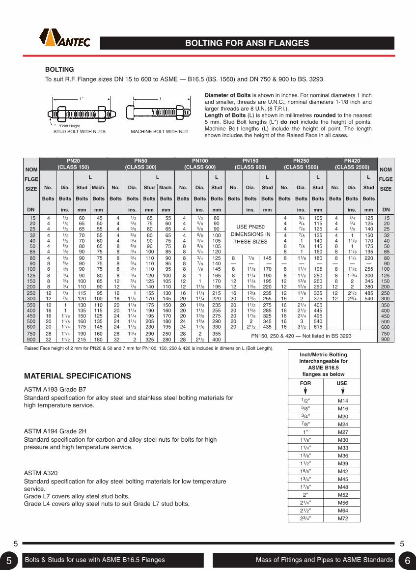
BOLTING FOR ANSI FLANGES
Bolts & Studs for use with ASME B16.5 Flanges Mass of Fittings and Pipes to ASME Standards
5 5
BOLTINGTo suit R.F. Flange sizes DN 15 to 600 to ASME — B16.5 (BS. 1560) and DN 750 & 900 to BS. 3293
Diameter of Bolts is shown in inches. For nominal diameters 1 inchand smaller, threads are U.N.C.; nominal diameters 1-1/8 inch andlarger threads are 8 U.N. (8 T.P.I.).Length of Bolts (L) is shown in millimetres rounded to the nearest5 mm. Stud Bolt lengths (L*) do not include the height of points.Machine Bolt lengths (L) include the height of point. The lengthshown includes the height of the Raised Face in all cases.
NOM
FLGE
SIZE Mach.
Bolts
mm
No.
Bolts
Dia.
Bolts
ins.
Stud
Bolts
mm
No.
Bolts
Dia.
Bolts
ins.
Stud
Bolts
mm
No.
Bolts
Dia.
Bolts
ins.
Stud
Bolts
mm
No.
Bolts
Dia.
Bolts
ins.
Stud
Bolts
mm
No.
Bolts
Dia.
Bolts
ins.
Stud
Bolts
mm
Mach.
Bolts
mmDN
NOM
FLGE
SIZE
DN
L L L L L L
PN150, 250 & 420 — Not listed in BS 3293
PN20(CLASS 150)
PN50(CLASS 300)
PN100(CLASS 600)
PN150(CLASS 900)
PN250(CLASS 1500)
PN420(CLASS 2500)
Raised Face height of 2 mm for PN20 & 50 and 7 mm for PN100, 150, 250 & 420 is included in dimension L (Bolt Length).
MATERIAL SPECIFICATIONS
ASTM A193 Grade B7Standard specification for alloy steel and stainless steel bolting materials forhigh temperature service.
ASTM A194 Grade 2HStandard specification for carbon and alloy steel nuts for bolts for highpressure and high temperature service.
ASTM A320Standard specification for alloy steel bolting materials for low temperatureservice.Grade L7 covers alloy steel stud bolts.Grade L4 covers alloy steel nuts to suit Grade L7 stud bolts.
*Point Height
STUD BOLT WITH NUTS MACHINE BOLT WITH NUT
L* L
Inch/Metric Boltinginterchangeable for
ASME B16.5flanges as below
FOR USE
4 3/4 125 154 3/4 125 204 7/8 140 254 1 150 324 11/8 170 408 1 175 508 11/8 195 658 11/4 220 80
— — — 908 11/2 255 1008 1-3/4 300 1258 2 345 150
12 2 380 20012 21/2 485 25012 23/4 540 300
350400450500600750900
15 4 1/2 60 45 4 1/2 65 5520 4 1/2 65 50 4 5/8 75 6025 4 1/2 65 55 4 5/8 80 6532 4 1/2 70 55 4 5/8 80 6540 4 1/2 70 60 4 3/4 90 7550 4 5/8 80 65 8 5/8 90 7565 4 5/8 90 75 8 3/4 100 8580 4 5/8 90 75 8 3/4 110 9090 8 5/8 90 75 8 3/4 110 95
100 8 5/8 90 75 8 3/4 110 95125 8 3/4 90 80 8 3/4 120 100150 8 3/4 100 85 12 3/4 125 105200 8 3/4 110 90 12 7/8 140 110250 12 7/8 115 95 16 1 155 130300 12 7/8 120 100 16 11/8 170 145350 12 1 130 110 20 11/8 175 150400 16 1 135 115 20 11/4 190 160450 16 11/8 150 125 24 11/4 195 170500 20 11/8 160 135 24 11/4 205 180600 20 11/4 175 145 24 11/2 230 195750 28 11/4 190 160 28 13/4 290 250900 32 11/2 215 180 32 2 325 280
4 1/2 80 4 3/4 1054 5/8 90 4 3/4 1154 5/8 90 4 7/8 1254 5/8 100 4 7/8 1254 3/4 105 4 1 1408 5/8 105 8 7/8 1458 3/4 120 8 1 1608 3/4 125 8 7/8 145 8 11/8 1808 7/8 140 — — — — — —8 7/8 145 8 11/8 170 8 11/4 1958 1 165 8 11/4 190 8 11/2 250
12 1 170 12 11/8 195 12 13/8 26012 11/8 195 12 13/8 220 12 15/8 29016 11/4 215 16 13/8 235 12 17/8 33520 11/4 220 20 13/8 255 16 2 37520 13/8 235 20 11/2 275 16 21/4 40520 11/2 255 20 15/8 285 16 21/2 44520 15/8 275 20 17/8 325 16 23/4 49524 15/8 290 20 2 345 16 3 54024 17/8 330 20 21/2 435 16 31/2 61528 2 35528 21/2 400
USE PN250DIMENSIONS INTHESE SIZES
Dia.
Bolts
ins.
No.
Bolts
Stud
Bolts
mm
1/2” M145/8” M163/4” M207/8” M24
1” M27
11/8” M30
11/4” M33
13/8” M36
11/2” M39
15/8” M42
13/4” M45
17/8” M48
2” M52
21/4” M56
21/2” M64
23/4” M72
5 6
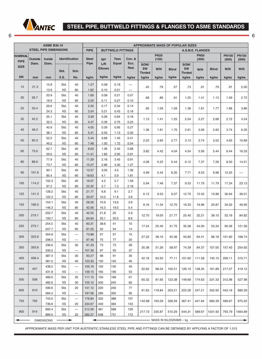
STEEL PIPE, BUTTWELD FITTINGS & FLANGES TO ASME STANDARDS
6 6
NOMINAL
PIPE
SIZE
DN mm mm
Identification
Sch.
No. kg/m kg/ea kg/ea kg/ea kg/ea kg/ea kg/ea kg/ea kg/ea kg/ea kg/ea kg/ea
ASME B36.10STEEL PIPE DIMENSIONS
OutsideDiam.
InsideDiam.
Std.
X.S.
PIPE
APPROXIMATE MASS OF POPULAR SIZES
BUTTWELD FITTINGS A.S.M.E. FLANGES
SteelPipe
90o
L/RElbows
TeesEqual
Con. &Ecc.Red.
SOW/SW
ThrdedW/N Blind
SOW/SW
ThrdedW/N Blind W/N W/N
PN20(150)
PN50(300)
PN100(600)
PN150(900)
APPROXIMATE MASS PER UNIT FOR AUSTENITIC STAINLESS STEEL PIPE AND FITTINGS CAN BE OBTAINED BY APPLYING A FACTOR OF 1.015
DIMENSIONS MASS IN KILOGRAMS – kg.
15 21.3
20 26.7
25 33.4
32 42.2
40 48.3
50 60.3
65 73.0
80 88.9
90 101.6
100 114.3
125 141.3
150 168.3
200 219.1
250 273.1
300 323.9
350 355.6
400 406.4
450 457
500 508
600 610
750 762
900 914
.45 .79 .57 .73 .91 .79 .91 2.00
.68 .86 .91 1.25 1.41 1.13 1.59 2.72
.95 1.09 1.09 1.36 1.81 1.77 1.86 3.86
1.13 1.41 1.25 2.04 2.27 2.68 2.72 4.54
1.36 1.81 1.70 2.81 3.06 2.83 3.74 6.35
2.22 2.83 2.77 3.13 3.74 3.52 4.65 10.89
3.82 4.42 4.04 4.54 5.56 5.44 6.44 16.33
4.08 5.22 5.44 6.12 7.37 7.26 8.50 14.51
4.99 5.44 6.35 7.71 9.53 9.98 12.25 ––
5.94 7.48 7.37 9.53 11.79 11.79 17.24 23.13
6.12 9.53 9.07 12.70 15.42 15.88 30.84 39.01
8.16 11.34 12.70 16.33 19.96 20.87 34.02 49.90
12.70 19.05 21.77 25.40 32.21 38.10 52.16 84.82
17.24 25.40 31.75 35.38 44.00 53.34 90.36 121.56
27.22 38.10 45.36 50.80 64.41 86.18 101.60 168.74
35.38 51.26 58.97 74.39 84.37 107.05 157.40 254.92
42.18 63.50 77.11 101.60 111.58 145.15 209.11 310.71
52.62 68.04 102.51 126.10 138.35 181.89 217.27 419.12
65.32 81.65 123.38 149.69 174.63 231.33 312.98 527.98
91.63 118.84 203.21 222.26 247.21 342.92 443.16 680.39
142.88 163.29 326.59 367.41 421.84 680.39 589.67 975.22
217.72 235.87 510.29 544.31 589.67 1031.92 793.79 1564.89
15.8 Std. 40 1.27 0.08 0.16 ––
13.9 XS 80 1.62 0.10 0.21 ––
20.9 Std. 40 1.69 0.08 0.21 0.07
18.9 XS 80 2.20 0.11 0.27 0.10
26.6 Std. 40 2.50 0.17 0.34 0.14
24.3 XS 80 3.24 0.21 0.43 0.18
35.1 Std. 40 3.39 0.28 0.64 0.18
32.5 XS 80 4.47 0.39 0.75 0.23
40.9 Std. 40 4.05 0.39 0.95 0.27
38.1 XS 80 5.41 0.50 1.13 0.32
52.5 Std. 40 5.44 0.68 1.45 0.41
49.2 XS 80 7.48 1.00 1.72 0.54
62.7 Std. 40 8.63 1.36 2.45 0.68
59.0 XS 80 11.41 1.82 2.95 0.91
77.9 Std. 40 11.29 2.18 3.45 0.91
73.7 XS 80 15.27 2.86 4.30 1.27
90.1 Std. 40 13.57 3.05 4.5 1.36
85.4 XS 80 18.63 4.1 5.9 1.81
102.3 Std. 40 16.07 4.2 5.7 1.59
97.2 XS 80 22.32 5.7 7.3 2.18
128.2 Std. 40 21.77 6.8 9.1 2.7
122.3 XS 80 30.97 10.0 11.8 3.8
154.1 Std. 40 28.26 10.9 13.6 3.9
146.3 XS 80 42.56 16.3 19.0 5.4
202.7 Std. 40 42.55 21.8 25 5.9
193.7 XS 80 64.64 33.1 33.5 8.6
254.5 Std. 40 60.31 38.6 41 10
247.7 XS 60 81.55 52 54 14
304.8 Std. –– 73.88 57 57 15
298.5 XS –– 97.46 75 77 20
336.6 Std. 30 81.33 73 73 28
330.2 XS –– 107.39 97 93 37
387.4 Std. 30 93.27 98 91 35
381.0 XS 40 123.30 130 120 46
438.2 Std. –– 105.16 120 135 40
431.8 XS –– 139.15 165 190 53
489.0 Std. 20 117.15 150 168 61
482.6 XS 30 155.12 200 245 82
590.6 Std. 20 141.12 220 240 77
584.2 XS –– 187.06 280 350 95
743.0 Std. –– 176.84 332 388 107
736.6 XS 20 234.67 440 484 143
895.4 Std. –– 212.56 481 588 129
889.0 XS 20 282.27 638 731 172

MEDIUM & HEAVY PIPE TO AUSTRALIAN STANDARDS
WORKING PRESSURES – WELDED JOINTS
Where AS 1074 pipe is used in pressure pipingcovered by AS 4041, the maximum pressure shallnot exceed 1210 kPa for AS 1074 pipe up to andincluding DN 100 and 1030 kPa for AS 1074 pipeexceeding DN 100.
END PROCESSING OPTIONS
• Plain End • Shouldered• Roll Grooved • Threaded
THREADED PIPE
Screwed on one or both ends in accordance withAS 1074. The tapered Whitworth thread usedcomplies with the requirements of AS 1722, Part1 and is suitable for both parallel and taperthreaded sockets.
SPECIFICATION
C250 pipe is manufactured and tested to meet therequirement of the following specifications:
• AS 1074 Steel tubes and tubulars for ordinaryservice.
• AS 1163 Structural steel hollow sections. (GradeC250, C250L0).
MECHANICAL PROPERTIES
Minimum Yield Strength 250MPa
Minimum Tensile Strength 320MPa
Minimum Elongation in 5.65 √So 20%
SUPPLY CONDITIONS
Surface Finish Black/Painted/Galvanized/ILG
Straightness
Thickness Tolerance
Dimension Tolerance
Standard Length 6.5m
Length Tolerance +50mm/-0mm
WORKING PRESSURES – THREADED JOINTS TAPER/PARALLEL THREAD
TYPE OF SERVICE
(mm)
Nom.SizeDN Med. Heavy Med. &
HeavyMedium
Press TempHeavy
Press TempMedium
Press TempHeavy
Press Temp
Water & Inert Oil LPG Fuel Oil Other Applications(including Steam & Compressed Air)
kPa kPa kPa kPa oC kPa oC kPa oC oCkPa
CHS Grade C250 MASS AND BUNDLING DATA – Calculated in accordance with AS 1163
(mm)
NominalSizeDN
(mm) (mm) W x H 6.5m m Black Galv. Black Galv. Black Galv.
Designationdo t
BundleDimensions
mm
LengthsPer
Bundle
MetresPer
Bundle
Nominal Mass
kg/m m/tonne tonnes
Mass per Bundle
DIMENSIONS BUNDLING MASS
25 2070 2410 140 1030 100 1210 192 1210 100 1210 192
32 1720 2070 140 1030 100 1030 192 1030 100 1030 192
40 1720 2070 140 1030 100 1030 192 1030 100 1030 192
50 1380 1720 140 860 100 860 192 860 100 860 192
65 1380 1720 –– 860 100 860 192 860 100 860 192
80 1380 1720 –– 860 100 860 192 860 100 860 192
100 1030 1380 –– 690 100 850 192 690 100 690 192
125 1030 1380 –– –– –– –– –– –– –– –– ––
150 860 1030 –– –– –– –– –– –– –– –– ––
26.9 x 2.6 CHS 20 M 350 306 127 825.5 1.56 1.62 642 613 1.29 1.32
3.2 CHS 20 H 350 306 127 825.5 1.87 1.93 535 522 1.54 1.59
33.7 x 3.2 CHS 25 M 372 327 91 591.5 2.41 2.49 415 406 1.43 1.47
4.0 CHS 25 H 372 327 91 591.5 2.94 3.02 340 330 1.74 1.78
42.4 x 3.2 CHS 32 M 383 337 61 396.5 3.10 3.20 322 310 1.23 1.27
4.0 CHS 32 H 383 337 61 396.5 3.80 3.90 263 255 1.51 1.54
48.3 x 3.2 CHS 40 M 436 384 61 396.5 3.57 3.68 280 270 1.41 1.46
4.0 CHS 40 H 436 384 61 396.5 4.38 4.49 228 221 1.74 1.78
60.3 x 3.6 CHS 50 M 422 374 37 240.5 5.03 5.18 199 192 1.21 1.25
4.5 CHS 50 H 422 374 37 240.5 6.19 6.33 161 157 1.49 1.52
76.1 x 3.6 CHS 65 M 533 472 37 240.5 6.43 6.61 156 150 1.55 1.59
4.5 CHS 65 H 533 472 37 240.5 7.93 8.12 126 123 1.91 1.95
88.9 x 4.0 CHS 80 M 445 397 19 123.5 8.37 8.58 120 116 1.03 1.06
4.9 CHS 80 H 445 397 19 123.5 10.3 10.5 96.8 94.4 1.28 1.30
101.6 x 4.0 CHS 90 M 508 454 19 123.5 9.63 9.88 104 100 1.19 1.22
4.9 CHS 90 H 508 454 19 123.5 11.9 12.2 84 81.7 1.47 1.50
114.3 x 4.5 CHS 100 M 571 509 19 123.5 12.2 12.4 82.2 79.8 1.50 1.54
5.4 CHS 100 H 571 509 19 123.5 14.5 14.3 69.1 67.4 1.79 1.82
139.7 x 5.0 CHS 125 M 698 382 13 84.5 16.6 16.9 60.2 58.6 1.40 1.43
5.4 CHS 125 H 698 382 13 84.5 17.9 18.2 55.9 54.6 1.51 1.54
165.1 x 5.0 CHS 150 M 660 451 10 65 19.7 20.1 50.7 49.3 1.28 1.31
5.4 CHS 150 H 660 451 10 65 21.7 21.57 45.9 46 1.38 1.41
NOTES: 1. M = Medium, H = Heavy
Refer to Australianstandards
Pipes to Australian Standards Medium/Heavy Pipes to Australian Standards Light/Extra Light7
7 7
8

Grade C350 pipe is a lightweight, high strengthpipe for general mechanical and structuralapplications.
C350 is manufactured by cold-forming and highfrequency electric resistance welding.
C350 is available in black, ILG and galvanizedfinishes.
Also available with one or both ends swaged asfollows:
SUPPLY CONDITIONSSurface Finish Black/ILG/Galvanized
Straightness
Thickness Tolerance
Dimension Tolerance
Standard Length 6.5m
Length Tolerance +50mm/-0mm
NB XL L
20 ✓ X
25 ✓ ✓
32 ✓ ✓
40 ✓ ✓
50 ✓ X
MECHANICAL PROPERTIESMinimum Yield Strength 350MPa
Minimum Tensile Strength 450MPa
Minimum Elongation in 5.65 √So 20%
SPECIFICATION
Grade C350 pipe is manufactured and tested tomeet the requirement of the followingspecifications:
• AS 1163 Structural Steel Hollow Sections(Grade C350, C350L0).
• AS/NZ 54792 Hot dip galvanized (zinc)coatings on ferrous hollow sections by acontinuous or a specialised process.
GALVANIZING
Grade C350 pipe is manufactured and tested tomeet the requirement of AS 4792 GalvanizedCoatings.
Min. Ave Coating Mass 300g/m2
The coating adherence of the galvanizing issatisfactory for the pipe to be bent to a radius 6times the diameter of the pipe.
WELDING
The following consumables are recommended byAS 1554.1 when welding C350 sections.
Manual metal-arc (MMAW) E41XX, E48XX
Gas metal-arc (MIG) (GMAW) W50X
CHS Grade C250 MASS AND BUNDLING DATA – Calculated in accordance with AS 1163
(mm)
NominalSizeDN
(mm) (mm) W x H 6.5m m Black Galv. Black Galv. Black Galv.
Designationdo t
BundleDimensions
mm
LengthsPer
Bundle
MetresPer
Bundle
Nominal Mass
kg/m m/tonne tonnes
Mass per Bundle
DIMENSIONS BUNDLING MASS
26.9 x 2.0 CHS 20 XL 350 306 127 825.5 1.23 1.29 814 767 1.010 1.070
2.3 CHS 20 LT 350 306 127 825.5 1.40 1.46 717 680 1.150 1.200
33.7 x 2.0 CHS 25 XL 372 327 91 591.5 1.56 1.64 640 602 0.920 0.970
2.6 CHS 25 LT 372 327 91 591.5 1.99 2.07 501 497 1.180 1.230
42.4 x 2.0 CHS 32 XL 383 337 61 396.5 1.99 2.10 502 473 0.790 0.830
2.6 CHS 32 LT 383 337 61 396.5 2.55 2.65 392 374 1.010 1.050
48.3 x 2.3 CHS 40 XL 436 384 61 396.5 2.61 2.73 383 364 1.030 1.080
2.9 CHS 40 LT 436 384 61 396.5 3.25 3.36 308 295 1.290 1.330
60.3 x 2.3 CHS 50 XL 422 374 37 240.5 3.29 3.44 304 288 0.790 0.830
2.9 CHS 50 LT 422 374 37 240.5 4.11 4.25 244 234 0.990 1.020
76.1 x 2.3 CHS 65 XL 533 472 37 240.5 4.19 4.33 239 231 1.007 1.040
3.2 CHS 65 LT 533 472 37 240.5 5.75 5.94 174 167 1.380 1.430
88.9 x 2.6 CHS 80 XL 445 397 19 123.5 5.53 5.75 181 174 0.683 0.710
3.2 CHS 80 LT 445 397 19 123.5 6.76 6.98 148 143 0.840 0.860
101.6 x 2.6 CHS 90 XL 508 454 19 123.5 6.35 6.60 158 152 0.784 0.815
3.2 CHS 90 LT 508 454 19 123.5 7.70 8.04 129 124 0.960 0.990
114.3 x 3.2 CHS 100 XL 572 510 19 123.5 8.77 9.05 114 110 1.083 1.118
3.6 CHS 100 LT 572 510 19 123.5 9.83 10.11 102 98.6 1.214 1.249
139.7 x 3.0 CHS 125 XL 698 382 13 84.5 10.11 10.50 98.9 95.2 0.855 0.887
3.5 CHS 125 LT 698 382 13 84.5 11.76 12.10 85.1 82.4 0.993 1.022
165.1 x 3.5 CHS 150 LT 660 451 10 65 13.95 14.40 71.7 69.4 0.907 0.936
Notes: 1. LT = Light, 2. XL = Extra Light
Note: The term “tube” is synonymous with the term “pipe”
Refer to Australianstandards
LIGHT/EXTRA LIGHT PIPE TO AUSTRALIAN STANDARDS
8 8

Flanges to AS.2129 Metric Bolts for use with AS.2129 Flanges9
9 9
10
FLANGES TO AUSTRALIAN STANDARDS
(1) All dimensions are in millimetres (mm).(2) Only metric preferred sizes listed, except for DN 750 which is a
Non-preferred size.* * (3) It is impractical to use flange thickness less than 12mm for
Steel Plate Flanges.* (4) Thickness includes 1.6mm height for the Raised Face.
† (5) The Raised Face is non-preferred for Table “H”.(6) It is normal practice to supply Steel Flanges to Tables A, D, C, E, F
and H. — Flat Faced.(7) All copper alloy flanges shall be Flat Faced.(8) All flanges shall be drilled to Standard Tables unless otherwise
specified. (For Bolt dimensions see separate page).
IMPORTANT: For DN 150 and DN 200 Flanges, the O.D. of pipe being used must be specified. Dimensions for Flange Tables A, C, K, S and T on application.
NOTES:
COPPER ALLOYT.3 –Plate or Boss or BlankT.10 – Plate or BossT.11 – Blank
FORGED OR PLATE STEELT.6 –Plate or Boss or Blank, or Weldneck
(Except for valves)T.18 – Plate or Blank or Weldneck (Except for valves)
TABLE D TABLE E TABLE F
FLANGE DRILLING FLANGE DRILLING FLANGE DRILLING
TABLE H TABLE J TABLE R
FLANGE DRILLING FLANGE DRILLING FLANGE DRILLING
Thick-ness
Thick-ness
BLANK OR BLIND FLANGE
BOSS FLANGE – SLIP ON WELD OR SCR. B.S.P.
PLATE FLANGESLIP ON WELD
DIMENSIONSFOR LOOSE FLANGES
WELD NECK FLANGE
DIAM.RAISED FACE DIAM.
RAISED FACE
1.6mm1.6mm
FLAT FACE FLAT FACE
DIAM.RAISED FACE
1.6mm FLAT FACE
NOMINAL
SIZE
DN
15 115 10 11 13 57 83 4 M16 115 16 57 83 4 M16 115 19 64 83 4 M16 1520 115 10 11 13 57 83 4 M16 115 16 57 83 4 M16 115 19 64 83 4 M16 2025 120 11 12 14 64 87 4 M16 120 19 64 87 4 M16 125 22 76 95 4 M16 2532 135 11 13 17 76 98 4 M16 135 19 76 98 4 M16 135 22 76 98 4 M16 32
40 140 13 14 17 83 105 4 M16 140 22 83 105 4 M16 150 25 89 114 4 M20 4050 165 13 16 19 102 127 4 M16 165 25 102 127 4 M20 165 25 102 127 8 M16 5065 185 14 17 19 114 146 8 M16 185 25 114 146 8 M20 185 29 114 146 8 M20 6580 205 16 19 22 127 165 8 M16 205 32 127 165 8 M20 205 32 127 165 8 M20 80
100 230 19 23 25 152 191 8 M16 230 35 152 191 8 M20 240 35 152 197 8 M24 100125 280 22 27 29 178 235 8 M20 280 38 178 235 8 M24 280 41 178 235 12 M24 125150 305 25 30 29 210 260 12 M20 305 38 210 260 12 M24 305 44 210 260 12 M24 150200 370 32 39 32 260 324 12 M20 370 41 260 324 12 M24 370 51 260 324 12 M27 200
250 430 35 45 35 311 381 12 M24 430 48 311 381 12 M27 430 60 311 387 16 M27 250300 490 38 52 41 362 438 16 M24 490 51 362 438 16 M27 510 70 362 457 16 M30 300350 550 41 58 48 419 495 16 M27 550 57 419 495 16 M30 585 79 419 527 16 M33 350400 610 44 64 54 483 552 20 M27 610 64 483 552 20 M30 640 89 483 584 20 M33 400
450 675 48 71 60 533 610 20 M30 675 70 533 610 20 M33 735 98 572 673 20 M36 450500 735 51 78 67 597 673 24 M30 735 79 597 673 24 M33 805 105 622 730 20 M39 500600 850 57 92 76 699 781 24 M33 850 92 699 781 24 M36 – – – – – – –
mm mm mm mm mm mm mm mm mm mm mm mm mm mm mm mm mm
OD
NOMINAL
SIZE
DN
THICKNESS
T10 T11*
T6
†
Dia.R/F
BoltCircleDia.
No.of
Bolts
Dia.of
Bolts OD *T6
*T18
Dia.R/F
BoltCircleDia.
No.of
Bolts
Dia.of
Bolts ODDia.R/F
BoltCircleDia.
No.of
Bolts
Dia.of
Bolts
15 95 6 5 67 4 M12 95 6 6 6 67 4 M12 95 8 8 10 67 4 M12 1520 100 6 5 73 4 M12 100 6 6 6 73 4 M12 100 8 8 10 73 4 M12 2025 115 8 5 83 4 M12 115 8 8 7 83 4 M12 120 10 10 10 87 4 M16 2532 120 8 6 87 4 M12 120 8 8 8 87 4 M12 135 10 10 13 98 4 M16 3240 135 10 6 98 4 M12 135 10 10 9 98 4 M12 140 11 11 13 105 4 M16 4050 150 10 8 114 4 M16 150 10 10 10 114 4 M16 165 11 12 16 127 4 M16 5065 165 11 8 127 4 M16 165 11 11 10 127 4 M16 185 13 13 16 146 8 M16 6580 185 13 10 146 4 M16 185 13 13 11 146 4 M16 205 14 15 16 165 8 M16 80
100 215 16 10 178 4 M16 215 16 16 13 178 8 M16 230 17 17 19 191 8 M16 100125 255 17 13 210 8 M16 255 17 17 14 210 8 M16 280 19 20 22 235 8 M20 125150 280 17 13 235 8 M16 280 17 17 17 235 8 M20 305 22 23 22 260 12 M20 150200 335 19 13 292 8 M16 335 19 20 19 292 8 M20 370 25 28 25 324 12 M20 200250 405 19 16 356 8 M20 405 22 25 22 356 12 M20 430 25 32 29 381 12 M24 250300 455 22 19 406 12 M20 455 25 28 25 406 12 M24 490 29 37 32 438 16 M24 300350 525 25 22 470 12 M24 525 25 32 29 470 12 M24 550 32 42 35 495 16 M27 350400 580 25 22 521 12 M24 580 25 36 32 521 12 M24 610 32 47 41 552 20 M27 400450 640 29 25 584 12 M24 640 29 41 35 584 16 M24 675 35 52 44 610 20 M30 450500 705 32 29 641 16 M24 705 32 46 38 641 16 M24 735 38 57 51 673 24 M30 500600 825 35 32 756 16 M27 825 38 – 48 756 16 M30 850 41 68 57 781 24 M33 600700 910 – 35 845 20 M27 910 – – 51 845 20 M30 935 – – 60 857 24 M33 700750 995 – 41 927 20 M30 995 – – 54 927 20 M33 1015 – – 67 940 28 M33 750800 1060 – 41 984 20 M33 1060 – – 54 984 20 M33 1060 – – 68 984 28 M33 800900 1175 – 48 1092 24 M33 1175 – – 64 1092 24 M33 1185 – – 76 1105 32 M36 900
1000 1255 – 51 1175 24 M33 1255 – – 67 1175 24 M36 1275 – – 83 1194 36 M36 10001200 1490 – 60 1410 32 M33 1490 – – 79 1410 32 M36 1530 – – 95 1441 40 M39 1200
NOMINAL
SIZE
DN mm mm mm mm mm mm mm mm mm mm mm mm mm mm mm mm mm
NOMINAL
SIZE
DN
OD
THICKNESS
T3**T6
BoltCircleDia.
No.of
Bolts
Dia.of
BoltsOD
THICKNESS
T10 T11**T6
BoltCircleDia.
No.of
Bolts
Dia.of
BoltsOD
THICKNESS
T10 T11**T6
BoltCircleDia.
No.of
Bolts
Dia.of
Bolts

I.S.O. METRIC HEXAGON STEEL BOLTS FOR USE WITH AS.2129 FLANGES
10 10
Steel hexagon Bolts and Nuts (XOX) are recommended for use within a temperature range of –50oC to+300oC. Outside of this temperature range, Stud Bolts should be used as recommended in AS.2528.
A quick reference chart for sizing bolts and nuts for a range of regularly used standard flanges is given below:
APPLICABLE TO PLATE & FORGED STEEL LOOSE FLANGES ONLY
Note: Integral valve flanges quite often differ in thickness to equivalent loose flanges. When integral flanges areinvolved due allowance should be made to bolt lengths.
Bolt lengths listed apply to flat-faced or 1.6mm raised faceflanges with allowance for 1.6mmgasket thickness.
*For approximate Stud BoltLengths take the XOX BoltLength and add the metricdiameter in mm rounded to thenearest 5mm increment up.
Note: (This does not includelength of point)
This chart shows bolt diameters asrecommended in AS.2129. Someof these are Non-preferred sizese.g. (M27), (M33) and (M39) whichare not readily available inAustralia.
Stud Bolts should be used asalternatives to bolts where the sizeis greater than M24 and it istherefore suggested that StudBolts as specified in AS.2528 orBS.4882 should be used.
Inch series boltsinterchangeable as follows:
FOR USE
1/4” M6 7/8” M24
5/16” M8 1” (M27)
3/8” M10 11/8” M30
1/2” M12 11/4” (M33)
5/8” M16 13/8” M36
3/4” M20 11/2” (M39)
FOR USE
BOLT HOLE DIAMETERS
For bolts to M24, clearance hole2mm larger.
Above M24, clearance hole 3mmlarger.
XOX BOLTS & NUTS
XOX is the trade term used forH.R.H. commercial steel bolts andnuts.
H.R.H. denotes Hexagon Head xRound Shank x Hexagon Nut.
XOX BOLTING
Temp. Range: –50oC to +300oC
Flange Specifications
Table Bolts Nuts
AS 1110 Gr.4.6
or AS1112 Gr.5
AS 1111 Gr.4.6
H AS 1110 Gr.8.8 AS 1112 Gr.8
Notes
High strength structural bolts to AS 1252 may be substituted for property class 8.8 bolts if agreed to by thepurchaser.
Bolts to AS 1252 are heavy hexagon series and the selection of such bolts would be subject to space beingavailable on the relevant flange.
15 4 M12 x 40mm* 4 M12 x 40mm* 4 M12 X 40mm* 4 M16 x 45mm*
20 4 M12 x 40mm* 4 M12 x 40mm* 4 M12 X 40mm* 4 M16 x 45mm*
25 4 M12 x 40mm* 4 M12 x 40mm* 4 M16 X 45mm* 4 M16 x 50mm*
32 4 M12 x 40mm* 4 M12 x 40mm* 4 M16 X 45mm* 4 M16 x 55mm*
40 4 M12 x 40mm* 4 M12 x 40mm* 4 M16 X 45mm* 4 M16 x 55mm*
50 4 M16 x 45mm* 4 M16 x 45mm* 4 M16 X 50mm* 4 M16 x 60mm*
65 4 M16 x 45mm* 4 M16 x 45mm* 8 M16 X 50mm* 8 M16 x 60mm*
80 4 M16 x 45mm* 4 M16 x 45mm* 8 M16 X 50mm* 8 M16 x 65mm*
100 4 M16 x 45mm* 8 M16 x 45mm* 8 M16 X 60mm* 8 M16 x 70mm*
125 8 M16 x 45mm* 8 M16 x 50mm* 8 M20 X 70mm* 8 M20 x 80mm*
150 8 M16 x 45mm* 8 M20 x 60mm* 12 M20 X 70mm* 12 M20 x 80mm*
200 8 M16 x 45mm* 8 M20 x 60mm* 12 M20 X 75mm* 12 M20 x 90mm*
250 8 M20 x 55mm* 12 M20 x 70mm* 12 M24 X 85mm* 12 M24 x 100mm*
300 12 M20 x 60mm* 12 M24 x 80mm* 16 M24 X 100mm* 16 M24 x 110mm*
350 12 M24 x 75mm* 12 M24 x 85mm* 16 M27 X 100mm* 16 M27 x 130mm*
400 12 M24 x 75mm* 12 M24 x 100mm* 20 M27 X 120mm* 20 M27 x 140mm*
450 12 M24 x 80mm* 16 M24 x 100mm* 20 M30 X 130mm* 20 M30 x 160mm*
500 16 M24 x 85mm* 16 M24 x 110mm* 24 M30 X 140mm* 24 M30 x 170mm*
600 16 M27 x 100mm* 16 M30 x 130mm* 24 M33 X 150mm* 24 M33 x 190mm*
700 20 M27 x 100mm* 20 M30 x 140mm* 24 M33 X 160mm*
750 20 M30 x 120mm* 20 M33 x 150mm* 28 M33 X 170mm*
800 20 M33 x 120mm* 20 M33 x 150mm* 28 M33 X 180mm*
900 24 M33 x 140mm* 24 M33 x 170mm* 32 M36 X 200mm*
1000 24 M33 x 140mm* 24 M36 x 180mm* 36 M36 X 220mm*
1200 32 M33 x 160mm* 32 M36 x 200mm* 40 M39 X 240mm*
NOMINAL
FLANGE
SIZE
DN
No. Bolts
Per
Flange
No. Bolts
Per
Flange
XOX
Bolt & Nut
dia. x lgth
No. Bolts
Per
Flange
XOX
Bolt & Nut
dia. x lgth
No. Bolts
Per
Flange
XOX
Bolt & Nut
dia. x lgth
TABLE D TABLE E TABLE F TABLE H
XOX
Bolt & Nut
dia. x lgth
All dimensions are in millimetres (mm).
Flat faced joint illustrated
Length
BoltDiam.
D, E,
& F
MASS
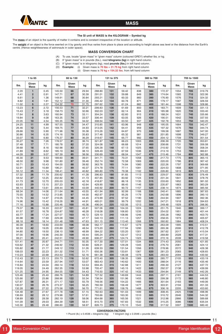
The SI unit of MASS is the KILOGRAM – Symbol kg
The mass of an object is the quantity of matter it contains and is constant irrespective of the location or altitude.
The weight of an object is the force exerted on it by gravity and thus varies from place to place and according to height above sea level or the distance from the Earth’scentre. (Hence weightlessness of astronauts in outer space).
MASS CONVERSION CHART(A) To use, locate “given mass” in “given mass” column (coloured GREY) whether lbs. or kg.(B) If “given mass” is in pounds (lbs.), read kilograms (kg) in right hand column.(C) If “given mass” is in kilograms (kg), read pounds (lbs.) in left hand column.(D) Example: (i) Given mass is 70 lbs = 31.75 kg from right hand column
(ii) Given mass is 70 kg = 154.32 lbs. from left hand column
1 to 65 66 to 130 131 to 375 380 to 700 705 to 1500
lbs.GivenMass kg lbs.
GivenMass kg lbs.
GivenMass kg lbs.
GivenMass kg lbs.
GivenMass kg
CONVERSION FACTORS1 Pound (lb.) x 0.4536 = kilograms (kg) 1 kilogram (kg) x 2.2046 = pounds (lbs.)
2.20 1 0.45 145.50 66 29.94 288.80 131 59.42 838 380 172.37 1554 705 319.794.41 2 0.91 147.71 67 30.39 291.01 132 59.88 849 385 174.64 1565 710 322.066.61 3 1.36 149.91 68 30.84 293.21 133 60.33 860 390 176.90 1576 715 324.328.82 4 1.81 152.12 69 31.30 295.42 134 60.78 871 395 179.17 1587 720 326.59
11.02 5 2.27 154.32 70 31.75 297.62 135 61.24 882 400 181.44 1598 725 328.8613.23 6 2.72 156.53 71 32.21 299.83 136 61.69 893 405 183.71 1609 730 331.1315.43 7 3.18 158.73 72 32.66 302.03 137 62.14 904 410 185.98 1620 735 333.4017.64 8 3.63 160.94 73 33.11 304.24 138 62.60 915 415 188.24 1631 740 335.6619.84 9 4.08 163.35 74 33.57 306.44 139 63.05 926 420 190.51 1642 745 337.9322.05 10 4.54 165.35 75 34.02 308.64 140 63.50 937 425 192.78 1653 750 340.2024.25 11 4.99 167.55 76 34.47 310.85 141 63.96 948 430 195.05 1664 755 342.4726.46 12 5.44 169.75 77 34.93 313.05 142 64.41 959 435 197.32 1676 760 344.7428.66 13 5.90 171.96 78 35.38 315.26 143 64.87 970 440 199.58 1687 765 347.0030.86 14 6.35 174.16 79 35.83 317.46 144 65.32 981 445 201.85 1698 770 349.2733.07 15 6.80 176.37 80 36.29 319.67 145 65.77 992 450 204.12 1709 775 351.5435.27 16 7.26 178.57 81 36.74 321.87 146 66.23 1003 455 206.39 1720 780 353.8137.48 17 7.71 180.78 82 37.20 324.08 147 66.68 1014 460 208.66 1731 785 356.0839.68 18 8.16 182.98 83 37.65 326.28 148 67.13 1025 465 210.92 1742 790 358.3441.89 19 8.62 185.19 84 38.10 328.49 149 67.59 1036 470 213.19 1753 795 360.6144.09 20 9.07 187.39 85 38.56 330.69 150 68.04 1047 475 215.46 1764 800 362.8846.30 21 9.53 189.60 86 39.01 341.71 155 70.31 1058 480 217.73 1775 805 365.1548.50 22 9.98 191.80 87 39.46 352.74 160 72.58 1069 485 220.00 1786 810 367.4250.71 23 10.43 194.00 88 39.92 363.76 165 74.84 1080 490 222.26 1797 815 369.6852.91 24 10.89 196.21 89 40.37 374.78 170 77.11 1091 495 224.53 1808 820 371.9555.12 25 11.34 198.41 90 40.82 385.80 175 79.38 1102 500 226.80 1819 825 374.2257.32 26 11.79 200.62 91 41.28 396.83 180 81.65 1113 505 229.07 1830 830 376.4959.52 27 12.25 202.82 92 41.73 407.85 185 83.92 1124 510 231.34 1841 835 378.7661.73 28 12.70 205.03 93 42.18 418.87 190 86.18 1135 515 233.60 1852 840 381.0263.93 29 13.15 207.23 94 42.64 429.90 195 88.45 1146 520 235.87 1863 845 383.2966.14 30 13.61 209.44 95 43.09 440.92 200 90.72 1157 525 238.14 1874 850 385.5668.34 31 14.06 211.64 96 43.55 451.94 205 92.99 1168 530 240.41 1885 855 387.8370.55 32 14.52 213.85 97 44.00 462.97 210 95.26 1179 535 242.68 1896 860 390.1072.75 33 14.97 216.05 98 44.45 473.99 215 97.52 1190 540 244.94 1907 865 392.3674.96 34 15.42 218.26 99 44.91 485.01 220 99.79 1202 545 247.21 1918 870 394.6377.16 35 15.88 220.46 100 45.36 496.04 225 102.06 1213 550 249.48 1929 875 396.9079.37 36 16.33 222.67 101 45.81 507.06 230 104.33 1224 555 251.75 1940 880 399.1781.57 37 16.78 224.87 102 46.28 518.08 235 106.60 1235 560 254.02 1951 885 401.4483.77 38 17.24 227.07 103 46.72 529.10 240 108.86 1246 565 256.28 1962 890 403.7085.98 39 17.69 229.28 104 47.17 540.13 245 111.13 1257 570 258.55 1973 895 405.9788.18 40 18.14 231.48 105 47.63 551.15 250 113.40 1268 575 260.82 1984 900 408.2490.39 41 18.60 233.69 106 48.08 562.17 255 115.67 1279 580 263.09 1995 905 410.5192.59 42 19.05 235.89 107 48.54 573.20 260 117.94 1290 585 265.36 2006 910 412.7894.80 43 19.50 238.10 108 48.99 584.22 265 120.20 1301 590 267.62 2017 915 415.0497.00 44 19.96 240.30 109 49.44 595.24 270 122.47 1312 595 269.89 2028 920 417.3199.21 45 20.41 242.51 110 49.90 606.27 275 124.74 1323 600 272.16 2039 925 419.58
101.41 46 20.87 244.71 111 50.35 617.30 280 127.01 1334 605 274.43 2050 930 421.85103.62 47 21.32 246.92 112 50.80 628.31 285 129.28 1345 610 276.70 2061 935 424.12105.82 48 21.77 249.12 113 51.26 639.33 290 131.54 1356 615 278.96 2072 940 426.38108.03 49 22.23 251.32 114 51.71 650.36 295 133.81 1367 620 281.23 2083 945 428.65110.23 50 22.68 253.53 115 52.16 661.38 300 136.08 1378 625 283.50 2094 950 430.92112.43 51 23.13 255.73 116 52.62 672.40 305 138.35 1389 630 285.77 2105 955 433.19114.64 52 23.59 257.94 117 53.07 683.43 310 140.62 1400 635 288.04 2116 960 435.46116.84 53 24.04 260.14 118 53.53 694.45 315 142.88 1411 640 290.30 2127 965 437.72119.05 54 24.49 262.35 119 53.98 705.47 320 145.15 1422 645 292.57 2138 970 439.99121.25 55 24.95 264.55 120 54.43 716.50 325 147.42 1433 650 294.84 2149 975 442.26123.46 56 25.40 266.76 121 54.89 727.52 330 149.69 1444 655 297.11 2161 980 444.53125.66 57 25.86 268.96 122 55.34 738.54 335 151.96 1455 660 299.38 2172 985 446.80127.87 58 26.31 271.17 123 55.79 749.56 340 154.22 1466 665 301.64 2183 990 449.06130.07 59 26.76 273.37 124 56.25 760.59 345 156.49 1477 670 303.91 2194 995 451.33132.28 60 27.22 275.58 125 56.70 771.61 350 158.76 1488 675 306.18 2205 1000 453.60134.48 61 27.67 277.78 126 57.15 782.63 355 161.03 1499 680 308.45 2425 1100 498.96136.69 62 28.12 279.98 127 57.61 793.66 360 163.30 1510 685 310.72 2646 1200 544.32138.89 63 28.58 282.19 128 58.06 804.68 365 165.56 1521 690 312.98 2866 1300 589.68141.09 64 29.03 284.39 129 58.51 815.70 370 167.83 1532 695 315.25 3086 1400 635.04143.30 65 29.48 286.60 130 58.97 826.73 375 170.10 1543 700 317.52 3307 1500 680.40
Mass Conversion Chart Flange Identification11
11 11
12
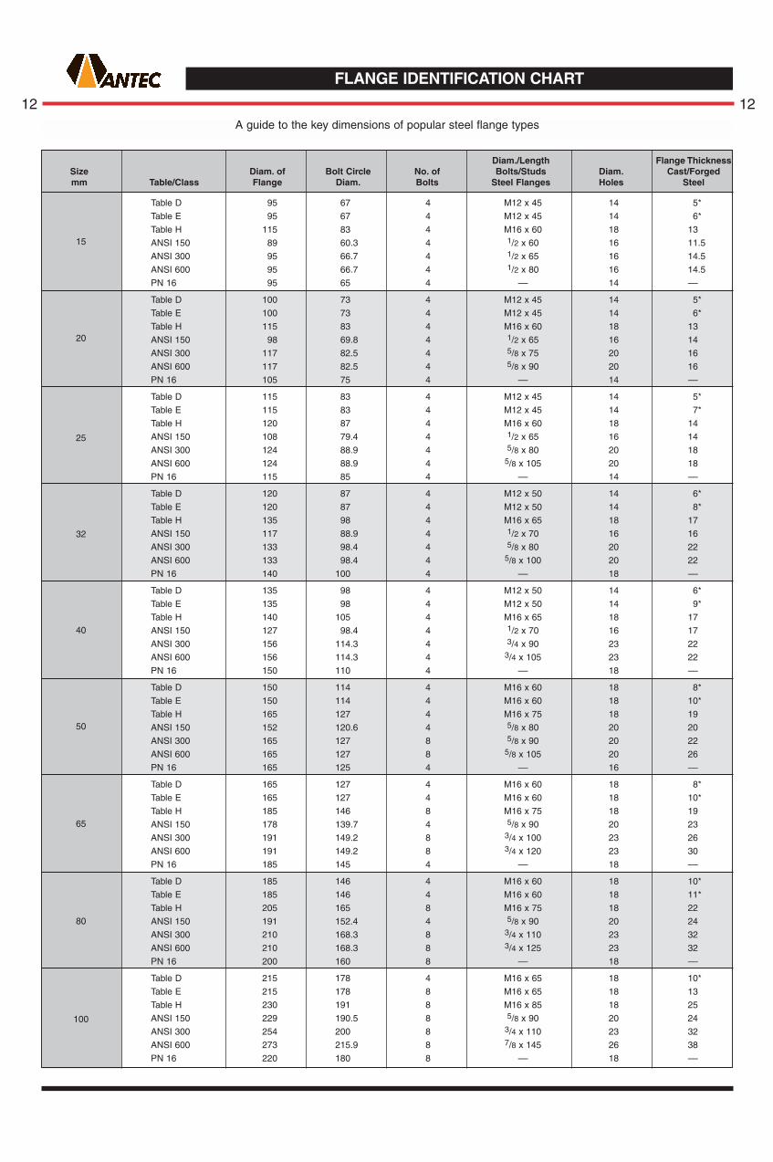
A guide to the key dimensions of popular steel flange types
Diam./Length Flange ThicknessSize Diam. of Bolt Circle No. of Bolts/Studs Diam. Cast/Forgedmm Table/Class Flange Diam. Bolts Steel Flanges Holes Steel
15
20
25
32
40
50
65
80
100
Table D 95 67 4 M12 x 45 14 5*
Table E 95 67 4 M12 x 45 14 6*
Table H 115 83 4 M16 x 60 18 13
ANSI 150 89 60.3 4 1/2 x 60 16 11.5
ANSI 300 95 66.7 4 1/2 x 65 16 14.5
ANSI 600 95 66.7 4 1/2 x 80 16 14.5
PN 16 95 65 4 –– 14 ––
Table D 100 73 4 M12 x 45 14 5*
Table E 100 73 4 M12 x 45 14 6*
Table H 115 83 4 M16 x 60 18 13
ANSI 150 98 69.8 4 1/2 x 65 16 14
ANSI 300 117 82.5 4 5/8 x 75 20 16
ANSI 600 117 82.5 4 5/8 x 90 20 16
PN 16 105 75 4 –– 14 ––
Table D 115 83 4 M12 x 45 14 5*
Table E 115 83 4 M12 x 45 14 7*
Table H 120 87 4 M16 x 60 18 14
ANSI 150 108 79.4 4 1/2 x 65 16 14
ANSI 300 124 88.9 4 5/8 x 80 20 18
ANSI 600 124 88.9 4 5/8 x 105 20 18
PN 16 115 85 4 –– 14 ––
Table D 120 87 4 M12 x 50 14 6*
Table E 120 87 4 M12 x 50 14 8*
Table H 135 98 4 M16 x 65 18 17
ANSI 150 117 88.9 4 1/2 x 70 16 16
ANSI 300 133 98.4 4 5/8 x 80 20 22
ANSI 600 133 98.4 4 5/8 x 100 20 22
PN 16 140 100 4 –– 18 ––
Table D 135 98 4 M12 x 50 14 6*
Table E 135 98 4 M12 x 50 14 9*
Table H 140 105 4 M16 x 65 18 17
ANSI 150 127 98.4 4 1/2 x 70 16 17
ANSI 300 156 114.3 4 3/4 x 90 23 22
ANSI 600 156 114.3 4 3/4 x 105 23 22
PN 16 150 110 4 –– 18 ––
Table D 150 114 4 M16 x 60 18 8*
Table E 150 114 4 M16 x 60 18 10*
Table H 165 127 4 M16 x 75 18 19
ANSI 150 152 120.6 4 5/8 x 80 20 20
ANSI 300 165 127 8 5/8 x 90 20 22
ANSI 600 165 127 8 5/8 x 105 20 26
PN 16 165 125 4 –– 16 ––
Table D 165 127 4 M16 x 60 18 8*
Table E 165 127 4 M16 x 60 18 10*
Table H 185 146 8 M16 x 75 18 19
ANSI 150 178 139.7 4 5/8 x 90 20 23
ANSI 300 191 149.2 8 3/4 x 100 23 26
ANSI 600 191 149.2 8 3/4 x 120 23 30
PN 16 185 145 4 –– 18 ––
Table D 185 146 4 M16 x 60 18 10*
Table E 185 146 4 M16 x 60 18 11*
Table H 205 165 8 M16 x 75 18 22
ANSI 150 191 152.4 4 5/8 x 90 20 24
ANSI 300 210 168.3 8 3/4 x 110 23 32
ANSI 600 210 168.3 8 3/4 x 125 23 32
PN 16 200 160 8 –– 18 ––
Table D 215 178 4 M16 x 65 18 10*
Table E 215 178 8 M16 x 65 18 13
Table H 230 191 8 M16 x 85 18 25
ANSI 150 229 190.5 8 5/8 x 90 20 24
ANSI 300 254 200 8 3/4 x 110 23 32
ANSI 600 273 215.9 8 7/8 x 145 26 38
PN 16 220 180 8 –– 18 ––
FLANGE IDENTIFICATION CHART
12 12

FLANGE IDENTIFICATION CHART
Diam./Length Flange ThicknessSize Diam. of Bolt Circle No. of Bolts/Studs Diam. Cast/Forgedmm Table/Class Flange Diam. Bolts Steel Flanges Holes Steel
125
150
200
375
450
500
600
400
It is impractical to use thickness less than 12.00mm for plate flanges.Dimensions AS 2129 – ANSI/ASME B16.5
Table D 255 210 8 M16 x 65 18 22
Table E 255 210 8 M16 x 65 18 14
Table H 280 235 8 M20 x 95 22 29
ANSI 150 254 215.9 8 3/4 x 90 23 24
ANSI 300 279 234.9 8 3/4 x 120 23 35
ANSI 600 330 266.7 8 1 x 165 29 45
PN 16 250 210 8 –– 18 ––
Table D 280 235 8 M16 x 65 18 13
Table E 280 235 8 M20x 65 22 17
Table H 305 260 12 M20 x 95 22 29
ANSI 150 279 241.3 8 3/4 x 100 23 26
ANSI 300 318 269.9 12 3/4 x 125 23 37
ANSI 600 356 292.1 12 1 x 170 29 48
PN 16 285 240 8 –– 22 ––
Table D 335 292 8 M16 x 65 18 13
Table E 335 292 8 M20 x 65 22 19
Table H 370 324 12 M20 x 100 22 32
ANSI 150 343 298.4 8 3/4 x 110 23 29
ANSI 300 381 330.2 12 7/8 x 140 26 41
ANSI 600 419 349.2 12 11/8 x 195 32 56
PN 10 340 295 8 –– 22 ––
PN 16 340 280 12 –– 22 ––
Table D 405 356 8 M20 x 75 22 ––
Table E 405 356 12 M20 x 75 22 22
Table H 430 381 12 M24 x 120 26 35
ANSI 150 406 361.9 12 7/8 x 115 29 30
ANSI 600 510 431.8 16 11/4 x 215 35 64
PN 10 395 350 8 –– 22 ––
PN 16 405 350 12 –– 22 ––
Table D 455 406 12 M20 x 85 22 22
Table E 455 406 12 M24 x 85 26 25
Table H 490 438 16 M24 x 110 26 41
ANSI 150 483 431.8 12 7/8 x 120 26 32
ANSI 300 520 450.8 16 11/8 x 170 32 51
PN 10 445 400 12 –– 22 ––
PN 16 450 410 12 –– 25 ––
Table D 525 470 12 M24 x 95 26 25
Table E 525 470 12 M24 x 95 26 29
Table H 550 495 16 M27 x 130 30 48
ANSI 150 535 476.2 12 1 x 130 29 35
ANSI 300 585 514.3 20 11/8 x 175 32 54
Table D 550 495 12 M24 x 95 26 22
Table E 550 495 12 M24 x 95 26 32
Table D 580 521 12 M24 x 95 26 22
Table E 580 521 12 M24 x 100 26 32
Table H 610 552 20 M27 x 140 30 54
ANSI 150 597 539.7 16 1 x 130 29 37
ANSI 300 650 571.5 20 11/4 x 190 35 57
Table D 640 584 12 M24 x 95 26 25
Table E 640 584 16 M24 x 120 26 35
Table H 675 610 20 M30 x 160 33 60
ANSI 150 635 577.8 16 11/8 x 150 32 40
ANSI 300 710 628.6 24 11/4 x 195 35 60
Table D 705 641 16 M24 x 110 26 29
Table E 705 641 16 M24 x 110 26 38
Table H 735 673 24 M30 x 170 33 67
ANSI 150 700 635 20 11/8 x 160 32 43
ANSI 300 775 685.8 24 11/4 x 205 35 64
Table D 825 756 16 M27 x 120 30 32
Table E 825 756 16 M30 x 140 33 48
Table H 850 781 24 M33 x 200 36 76
ANSI 150 815 749.3 20 11/4 x 175 35 48
ANSI 300 915 812.8 24 11/2 x 230 42 70
350
300
250
Flange Identification Pressure - Stress Conversion Charts
13 13
13 14

PRESSURE
14 14The SI unit of pressure and stress is the NEWTON PER SQUARE METRE which has been given the special name PASCAL – Symbol Pa.
The pascal is too small for most normal uses and suitable multiple units preferred for Australia are:
kilopascal: Symbol – kPa (= 1000 Pa) megapascal: Symbol – MPa (= 1,000,000 Pa)
(1 N/m2 = 0.000145 lbf/in2 = 1Pa) (1 N/mm2 = 145 lbf/in2 = 1MPa)
PSI (lbf/in2) to kPa • PRESSURE – STRESS CONVERSION CHART(A) To use, locate “given pressure” in “given pressure” column (coloured GREY) whether lbf/in2 or kPa.(B) If “given pressure” is in pounds force per square inch (lbf/in2), read kilopascals (kPa) in right hand column.(C) If “given pressure” is in kilopascals (kPa), read pounds force per square inch (lbf/in2) in left hand column.(D) Example: (i) Given pressure is 100 lbf/in2 = 689 kPa from right hand column
(ii) Given pressure is 100kPa = 14.50 lbf/in2 from left hand column
1 to 35 36 to 70 71 to 125 130 to 80,000
lbf/in2Given
Pressure kPa lbf/in2Given
Pressure kPa lbf/in2Given
Pressure kPa lbf/in2Given
Pressure kPa = MPa
0.15 1 6.89 5.22 36 248.21 10.30 71 490 18.85 130 896 = 0.900.29 2 13.79 5.37 37 255.11 10.44 72 496 19.58 135 931 = 0.930.44 3 20.68 5.51 38 262.00 10.59 73 503 20.31 140 965 = 0.970.58 4 27.58 5.66 39 268.90 10.73 74 510 21.03 145 1000 = 1.000.73 5 34.47 5.80 40 275.79 10.88 75 517 21.76 150 1034 = 1.03
0.87 6 41.37 5.95 41 282.69 11.02 76 524 22.48 155 1069 = 1.071.02 7 48.26 6.09 42 289.58 11.17 77 531 23.21 160 1103 = 1.101.16 8 55.16 6.24 43 296.48 11.31 78 538 23.93 165 1138 = 1.141.31 9 62.05 6.38 44 303.37 11.46 79 545 24.61 170 1172 = 1.171.45 10 68.95 6.53 45 310.26 11.60 80 552 25.38 175 1207 = 1.21
1.60 11 75.84 6.67 46 317.16 11.75 81 558 26.11 180 1241 = 1.241.74 12 82.74 6.82 47 324.05 11.89 82 565 26.83 185 1276 = 1.281.89 13 89.63 6.96 48 330.95 12.04 83 572 27.56 190 1310 = 1.312.03 14 96.53 7.11 49 337.84 12.18 84 579 28.28 195 1344 = 1.342.18 15 103.42 7.25 50 344.74 12.33 85 586 29.01 200 1379 = 1.38
2.32 16 110.32 7.40 51 351.63 12.47 86 593 36.26 250 1724 = 1.732.47 17 117.21 7.54 52 358.53 12.62 87 600 43.51 300 2068 = 2.072.61 18 124.11 7.69 53 365.42 12.70 88 607 58.02 400 2758 = 2.762.76 19 131.00 7.83 54 372.32 12.91 89 614 72.52 500 3447 = 3.452.90 20 137.90 7.98 55 379.21 13.05 90 621 108.78 750 5171 = 5.17
3.05 21 144.79 8.12 56 386.11 13.20 91 627 145.04 1000 6894 = 6.893.19 22 151.69 8.27 57 393.00 13.34 92 634 217.56 1500 10,342 = 10.343.34 23 158.58 8.41 58 399.90 13.49 93 641 290.08 2000 13,790 = 13.793.48 24 165.47 8.56 59 406.79 13.63 94 648 435.11 3000 20,684 = 20.683.63 25 172.37 8.70 60 413.69 13.78 95 655 580.15 4000 27,579 = 27.58
3.77 26 179.26 8.85 61 420.58 13.92 96 662 725.19 5000 34,473 = 34.473.92 27 186.16 8.99 62 427.48 14.07 97 669 1,450.38 10,000 68,948 = 68.954.06 28 193.05 9.14 63 434.37 14.21 98 676 2,175.57 15,000 103,421 = 103.44.21 29 199.95 9.28 64 441.26 14.34 99 683 2,900.76 20,000 137,895 = 137.94.35 30 206.84 9.43 65 448.16 14.50 100 689 4,351.14 30,000 206,843 = 206.8
4.50 31 213.74 9.57 66 455.05 15.23 105 724 5,801.52 40,000 275,790 = 275.84.64 32 220.63 9.72 67 461.95 15.95 110 758 7,251.90 50,000 344,738 = 344.74.79 33 227.53 9.86 68 468.84 16.68 115 793 8,702.28 60,000 413.686 = 413.74.93 34 234.42 10.01 69 475.74 17.40 120 827 10,152.7 70,000 482,633 = 482.65.08 35 241.32 10.15 70 482.63 18.13 125 862 11,603.0 80,000 551,581 = 551.6
NOTE: IT IS USUAL FOR PRESSURES IN EXCESS OF 1000 kPa TO BE EXPRESSED IN MEGAPASCALS – MPa
1 megapascal (MPa) = 1000 kilopascals (kPa) = 1 newton per mm2 (N/mm2) = 145 lbf/in2
USEFUL CONVERSION FACTORS – APPROXIMATE
NOTE: lbf/in2 (pounds force per square inch) is often expressed as PSI (pounds per square inch)
MULTIPLY BY TO OBTAIN
TO OBTAIN BY DIVIDE
1.0197 kg f/cm2
100.0 kPa
14.504 lbf/in2
0.1 MPa
14.223 lbf/in2
98.07 kPa
0.09807 MPa
1422.33 lbf/in2
9.807 MPa
0.635 ton f/in2
bars
kg f / cm2
kg f / mm2
MULTIPLY BY TO OBTAIN
TO OBTAIN BY DIVIDE
6.895 kPa
0.00689 MPa
15.444 MPa
lb f/in2 (PSI)
ton f/in2
APPROXIMATE EQUIVALENTS
1 Atmosphere (atm) = 14.696 lbf/in2
1 bar = 14.50 lbf/in2
1 kg f/cm2 = 14.22 lbf/in2
100 kPa (1 bar) = 14.50 lbf/in2

TEMPERATURE
The SI Unit of thermodynamic temperature is the KELVIN – Symbol K. For most practical purposes of temperature measurement and mostcalculations involving temperatures, DEGREE CELSIUS, symbol oC will be used. The name CELSIUS was adopted internationally in 1948 instead ofCentigrade, to avoid possible confusion with the identically named unit of angle used in some European countries.
TEMPERATURE CONVERSION CHART(A) To use, locate “given temperature” in “given temperature” column (coloured GREY) whether oC or oF.(B) If “given temperature” is in degrees Celsius (oC), read degrees Fahrenheit (oF) in right hand column.(C) If “given temperature” is in degrees Fahrenheit (oF), read degrees Celsius (oC) in left hand column.(D) Example: (i) Given temperature is 35oC = 95oF from right hand column
(ii) Given temperature is 35oF = 1.7oC from left hand column
–320 to 27 28 to 77 78 to 235 240 to 485 490 to 2400
oCGivenTemp.
oF oCGivenTemp.
oF oCGivenTemp.
oF oCGivenTemp.
oF oCGivenTemp.
oF
–196 –320 –– – 2.2 28 82.4 25.6 78 172.4 116 240 464 254 490 914
–184 –300 –– – 1.7 29 84.2 26.1 79 174.2 118 245 473 257 495 923
–173 –280 –– – 1.1 30 86.0 26.7 80 176.0 121 250 482 260 500 932
–162 –260 –436 – 0.6 31 87.8 27.2 81 177.8 124 255 491 266 510 950
–151 –240 –400 0.0 32 89.6 27.8 82 179.6 127 260 500 271 520 968
–140 –220 –364 0.6 33 91.4 28.3 83 181.4 129 265 509 277 530 986
–129 –200 –328 1.1 34 93.2 28.9 84 183.2 132 270 518 282 540 1004
–115 –175 –283 1.7 35 95.0 29.4 85 185.0 135 275 527 288 550 1022
–101 –150 –238 2.2 36 96.8 30.0 86 186.8 138 280 536 293 560 1040
– 90 –130 –202 2.8 37 98.6 30.6 87 188.6 141 285 545 299 570 1058
– 84 –120 –184 3.3 38 100.4 31.1 88 190.4 143 290 554 304 580 1076
– 79 –110 –166 3.9 39 102.2 31.7 89 192.2 146 295 563 310 590 1094
– 73 –100 –148 4.4 40 104.0 32.2 90 194.0 149 300 572 316 600 1112
– 68 – 90 –130 5.0 41 105.8 32.8 91 195.8 152 305 581 321 610 1130
– 62 – 80 –112 5.6 42 107.6 33.3 92 197.6 154 310 590 327 620 1148
– 57 – 70 – 94 6.1 43 109.4 33.9 93 199.4 157 315 599 332 630 1166
– 51 – 60 – 76 6.7 44 111.2 34.4 94 201.2 160 320 608 338 640 1184
– 46 – 50 – 58 7.2 45 113.0 35.0 95 203.0 163 325 617 343 650 1202
– 40 – 40 – 40 7.8 46 114.8 35.6 96 204.8 166 330 626 349 660 1220
– 34 – 30 – 22 8.3 47 116.6 36.1 97 206.6 168 335 635 354 670 1238
– 29 – 20 – 4 8.9 48 118.4 36.7 98 208.4 171 340 644 360 680 1256
– 23 – 10 14 9.4 49 120.2 37.2 99 210.2 174 345 653 366 690 1274
– 17.8 0 32 10.0 50 122.0 37.8 100 212.0 177 350 662 371 700 1292
– 17.2 1 33.8 10.6 51 123.8 41 105 221 179 355 671 377 710 1310
– 16.7 2 35.6 11.1 52 125.6 43 110 230 182 360 680 382 720 1328
– 16.1 3 37.4 11.7 53 127.4 46 115 239 185 365 689 388 730 1346
– 15.6 4 39.2 12.2 54 129.2 49 120 248 188 370 698 393 740 1364
– 15.0 5 41.0 12.8 55 131.0 52 125 257 191 375 707 399 750 1382
– 14.4 6 42.8 13.3 56 132.8 54 130 266 193 380 716 404 760 1400
– 13.9 7 44.6 13.9 57 134.6 57 135 275 196 385 725 410 770 1418
– 13.3 8 46.4 14.4 58 136.4 60 140 284 199 390 734 416 780 1436
– 12.8 9 48.2 15.0 59 138.2 63 145 293 202 395 743 421 790 1454
– 12.2 10 50.0 15.6 60 140.0 66 150 302 204 400 752 427 800 1472
– 11.7 11 51.8 16.1 61 141.8 68 155 311 207 405 761 432 810 1490
– 11.1 12 53.6 16.7 62 143.6 71 160 320 210 410 770 438 820 1508
– 10.6 13 55.4 17.2 63 145.4 74 165 329 213 415 779 443 830 1526
– 10.0 14 57.2 17.8 64 147.2 77 170 338 216 420 788 454 850 1562
– 9.4 15 59.0 18.3 65 149.0 79 175 347 218 425 797 468 875 1607
– 8.9 16 60.8 18.9 66 150.8 82 180 356 221 430 806 482 900 1652
– 8.3 17 62.6 19.4 67 152.6 85 185 365 224 435 815 510 950 1742
– 7.8 18 64.4 20.0 68 154.4 88 190 374 227 440 824 538 1000 1832
– 7.2 19 66.2 20.6 69 156.2 91 195 383 229 445 833 566 1050 1922
– 6.7 20 68.0 21.1 70 158.0 93 200 392 232 450 842 593 1100 2012
– 6.1 21 69.8 21.7 71 159.8 96 205 401 235 455 851 621 1150 2102
– 5.6 22 71.6 22.2 72 161.6 99 210 410 238 460 860 649 1200 2192
– 5.0 23 73.4 22.8 73 163.4 102 215 419 241 465 869 704 1300 2372
– 4.4 24 75.2 23.3 74 165.2 104 220 428 243 470 878 760 1400 2552
– 3.9 25 77.0 23.9 75 167.0 107 225 437 246 475 887 816 1500 2732
– 3.3 26 78.8 24.4 76 168.8 110 230 446 249 480 896 1093 2000 3632
– 2.8 27 80.6 25.0 77 170.6 113 235 455 252 485 905 1316 2400 4352
CONVERSION FACTORS
DEGREES FAHRENHEIT TO CELSIUS DEGREES CELSIUS TO FAHRENHEIT(oF – 32) x 5/9 = oC (oC x 9/5) + 32 = oF
Temperature Conversion Chart Useful Conversion Factors15
15 15
16

USEFUL CONVERSION FACTORS – IMPERIAL TO METRIC (Approximate)
16 16“SI” denotes the INTERNATIONAL SYSTEM of Metric Units adopted in Australia
MULTIPLY COLUMN “A” BY COLUMN “B”TO OBTAIN COLUMN “C”THIS TABLE MAY BE USED IN TWO WAYS: ALTERNATIVELY
DIVIDE COLUMN “C” BY COLUMN “B”TO OBTAIN COLUMN “A”
REMARKSA
MULTIPLYB
BYC
TO OBTAIN REMARKSA
MULTIPLYB
BYC
TO OBTAIN
AREA: Symbol m2
The SI unit of AREA isthe SQUARE METRE.
DENSITY: Symbol kg/m3
The SI unit of DENSITY isthe kilogram per cubicmetre.
Square inches 645.16 mm2
Square feet 0.929 m2
Square yards 0.836 m2
Acre 4047 m2
Hectare (ha) 10 000 m2
lb/in3 27.68 t/m3
lb/ft3 16.02 kg/m3
lb/yd3 0.5933 kg/m3
ENERGY: Symbol J
The SI unit of ENERGY isthe JOULE.
1 J = 1 N.m
A joule is the energyexpended or the workdone when a force of onenewton moves the pointof application a distanceof one metre in thedirection of that force.
1.ELECTRICALENERGY
kilowatt hour (kW.h) 3.6 MJ
2.HEAT ENERGYBritish thermal unit(Btu) 1.055 kJBtu/gal 0.2321 kJ/L ††Btu/ft3 37.26 kJ/m3
3.MECHANICALENERGY
foot poundalft.pdl .04214 Jinch pound-forcein.lbf 0.1130 Jfoot pound-forceft.lbf 1.356 Jfoot ton forceft.tonf 3.037 kJMetre kilogramforce m.kgf 9.807 J
FORCE: Symbol N(NEWTON)The SI unit of FORCE(kg.m/s2) has been giventhe special name – NEWTON.
The newton is the forcewhich when applied to abody having a mass ofone kilogram, causes anacceleration of one metreper second in the directionof application of the force.
Poundal (pdl) 0.1383 N
Pound-force (lbf) 4.448 N
ton-force (tonf) 9.964 kN
*kilogram-force(kgf) 9.807 N
*also known askilopond (kp)
FORCE PER UNITLENGTH:The SI unit is NEWTONPER METRE:Symbol N/m
pounds-force perinch (lbf/in) 175.1 N/m
pounds-force perfoot (lbf/ft) 14.59 N/m
ton-force perfoot (ton/ft) 32.69 kN/m
LENGTH: Symbol mThe SI unit of LENGTH isthe METRE.
inches 25.4 millimetres (mm)
feet 0.3048 metres (m)
yards 0.9144 metres (m)
chain 20.12 metres (m)
mile 1609 metres (m)
mile 1.609 kilometres (km)
MASS: Symbol kgThe SI unit of MASS isthe KILOGRAM.
ounce 28.35 grams (g)
pound 0.4536 kilograms (kg)
slug 14.59 kg
ton (2240 lb) 1016.05 kg
short ton (2000 lb) 907.2 kg
ton (2240 lb) 1.016 tonne (t)
pounds per foot(lb/ft) 1.488 kg/m
pounds per yard(lb/yd) 0.4961 kg/m
POWER: Symbol W
The SI unit of POWER isthe WATT.
Btu per hour(Btu/hr) 0.2931 W
horsepower (hp) 0.7457 kW
ton of refrigeration 3.517 kW
PRESSURE: Symbol Pa
The SI unit ofPRESSURE or stress isthe NEWTON PERSQUARE METRE whichhas been given the namePASCAL.
1 N/m2 = 1Pa =0.000145lbf/in2
A pascal is the pressureor stress which ariseswhen a force of onenewton is applieduniformly over an area ofone square metre.
lbf/in2 6.895 kPa
kip/in2 (1000 psi) 6.895 MPa
lbf/ft2 47.88 Pa
kgf/cm2 98.07 kPa
bar 100 kPa
Vertical column(head) of water.(H20 at 20oC)metres of water 9.79 kPa
feet of water 2.984 kPa
torr (vacuum) 0.1333 kPa
1mm Hg. (mercury) 0.1333 kPa
1in. Hg. (mercury) 3.386 kPa
atmosphere (atm) 101.325 kPa
microns 0.133 Pa
TORQUE: Symbol N.m(Moment of force)
The SI unit of TORQUE isthe NEWTON METRE.The newton metre is thework done when a forceof one newton moves thepoint of application adistance of one metre inthe direction of that force.
1 N.m = 1 J
Poundal-footpdl.ft .04214 N.mpound-force inchlbf.inch 0.1130 N.mlbf.inch 1.152 kgf.cmpound-force feetlbf.ft 1.356 N.mlbf.ft 13.83 kgf.cmton-force feettonf.ft 3.037 kN.mkilogram-forcekgf.m 9.807 N.mkgf.cm 0.09807 N.m
VELOCITY: Symbol m/s
The SI unit of VELOCITYis the METRE PERSECOND.
ft. per second (ft/s) 0.3048 m/s
ft. per minute (ft/min) 0.00508 m/s
miles per hour 0.4470 m/s
miles per hour 1.609 km/h
VOLUME: RATE OFFLOW Symbol m3/s
The SI unit of VOLUMERATE OF FLOW is theCUBIC METRE PERSECOND.
Imp. gal. per minute(gal/min) .0000758 m3/s
Imp. gal. per minute 0.272765 m3/hr
Imp. gal. per minute .0758 litre per second (L/s)
cubic ft. per minute .000472 m3/s
cubic ft. per minute 0.472 litre per second(L/s) 1 m3 = 1 kL
SUNDRY ITEMS: miles per gallon 0.3540 km per litre
gallons per mile 2.825 litres per km
VOLUME: CAPACITY:Symbol m3
The SI unit of VOLUME isthe CUBIC METRE.
NOTE: ††Capital “L” is now the legalpreferred symbol for litrein Australia.
DRY:
cubic inch (in3) 16387 mm3
cubic foot (ft3) 0.02832 m3
cubic yard (yd3) 0.7646 m3
litre (L) †† 1 000 000 mm3
litre (L) †† 0.001 m3
gallons (Imp.) 0.004546 m3
IMPERIAL LIQUID
fluid ounce 28.41 millilitre (ml)
pint (20 fl. oz) 568.3 millilitre (ml)
quart (2 pints) 1.137 litre (L) ††
gallon (Imp.) 4.546 litre (L) ††
gallon (US) 3.785 litre (L) ††
litre (water 4oC) 1.000 kilogram (kg)
Imp. gallons (water 20oC) 4.536 kilograms (kg)
TEMPERATUREThe SI unit of TEMPERATURE is the KELVIN – Symbol K
For most practical purposes of temperature measurement and most calculations involving temperatures, degrees Celsius, symbol oC will be used.
DEGREES FAHRENHEIT TO CELSIUS DEGREES CELSIUS TO FAHRENHEIT(oF – 32) x 5/9 = oC (oC x 9/5) + 32 = oF

All trademarks are property of their respective owners.
This information is provided for your assistance. However we are obliged to draw your attention to the following: Antec provides the information contained in this brochure as a guide only for your information.Antec has taken reasonable care to ensure the accuracy of the material but you should not rely on the
whole or any part of the information. Technology is changing rapidly and product specifications and or manufacturing techniques may have changed since the first publication date of this document. Antecexpressly disclaims all liability whatsoever for (including any direct or indirect loss or damage, costs or expenses howsoever incurred by any person) or reliance on the whole or any part of the information contained in or omitted from this brochure. Antec recommends that you verify any information regardingproducts with your independent expert adviser and rely solely on that adviser’s recommendations.