Embed Size (px)
Citation preview
1 of 8 © 2009 D 090 - 07/09
D 090 07/09Snow / Ice Sensor 090 / 094, Sensor Socket 091
- Data Brochure
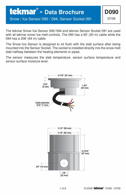
The tekmar Snow / Ice Sensor 090 / 094 and tekmar Sensor Socket 091 are used with all tekmar snow / ice melt controls. The 090 has a 65’ (20 m) cable while the 094 has a 208’ (64 m) cable.
The Snow / Ice Sensor is designed to sit flush with the slab surface after being mounted into the Sensor Socket. The socket is installed directly into the snow melt slab halfway between the heating elements or pipes.
The sensor measures the slab temperature, sensor surface temperature and sensor surface moisture level.
3-7/16” (87 mm)
3/16”(5 mm) 1-3/4”
(45 mm)
Cable diameter5/16” (7 mm)
3-1/2” (89 mm)
3-1/8” (80 mm)
3/4” (19 mm)
3-13/16”(97 mm)
7/8”(22 mm)
© 2009 D 090 - 07/09 2 of 8
InstallationCautionImproper installation and operation of this sensor could result in damage to equipment and possibly even personal injury. It is your responsibility to ensure that this sensor is safely installed according to all applicable codes and standards. Please follow these step-by-step instructions to gain a full understanding of this device.
STEP ONE — — GETTING READYCheck the Contents
Check the contents of this package. If any of the contents listed are missing or damaged, please refer to the Limited Warranty and Product Return Procedure on the back of this brochure and contact your wholesaler or tekmar sales representative for assistance.
Type 090 includes: • One Snow / Ice Sensor 090 with “O” ring • Four, #6-32 x 3/8” screws • Four, #4-40 x 7/16” screws • One Data Brochure D 090
Type 094 includes: •• One Snow / Ice Sensor 094 with “O” ring •• Four, #6-32 x 3/8” screws •• Four, #4-40 x 7/16” screws •• One Data Brochure D 090
Type 091 includes: •• One Snow / Ice Sensor Socket 091 •• One protective plastic plug •• One plastic mounting plate •• Eight, #6-32 x 3/8” screws •• One Data Brochure D 090
STEP TWO — — MOUNTING THE SENSORLocation of the Sensor
The location of the snow / ice sensor determines how well the snow melt detector responds to conditions on the snow melting slab. The sensor measures the temperature of the slab surface, and would normally be installed in a location that is representative of the average surface temperature and moisture conditions. The only exception to this practice would be those applications where the sensor is placed in a specific problem area where ice or snow often forms first.
The installer should be careful to place the sensor in a location where it will not be affected by abnormal temperature conditions that may occur near buildings, hot air exhaust ducts or other heat sources, or sunny areas within a larger slab area.
As well as reading temperatures, the sensor also detects surface water. The installer should be careful not to place the sensor where standing water could accumulate on its surface. Standing water in the socket may cause the snow melt system to be held on far longer than necessary, as the control will be getting a signal that water is present even though the rest of the slab surface may be dry. In addition, the sensor should not be placed in areas where drainage is considerably better than the surrounding area.
The snow / ice sensor should not be installed in locations where vehicles park, near building overhangs or near trees since this may interfere with snow fall accumulation. If in doubt about the location of these obstacles, a second spare
•
•
•
•

3 of 8 © 2009 D 090 - 07/09
socket and conduit can be installed in order to provide a backup sensor location if the first location is not found to be ideal.
Vehicle tire and pedestrian traffic can track water and contaminants onto the snow melt area. If the snow / ice sensor is located in the traffic area, snow melting will be triggered by the passing traffic. This may be desirable in commercial areas where excessive traffic can cause the surface to become icy. In residential installations, the amount of traffic is usually limited, and it may be desirable to locate the snow / ice sensor away from the traffic area. This will reduce the number of snow melt events that occur and thereby reduce the annual fuel consumption.
The location of the sensor should be midway between the heating pipes or elements.
Conduit
Place the sensor socket at the chosen location and run a conduit for the cable from the socket to the snow / ice detection control. If more than 210’ (64 m) of cable is required to reach the control, run the conduit to a weatherproof junction box. The sensor cable should be run in its own conduit and not in combination with high voltage wiring.
The conduit length from the sensor to the junction box should be less than the 210’ (64 m) of cable supplied with the 094 snow / ice sensor.
At the junction box, additional 18 AWG, 5 conductor cable can be spliced on to increase the total length to 500’ (150 m) from the sensor to control.
Avoid tying the conduit to the rebar within 6’ (2 m) of the socket. This allows the rebar grid to move without disturbing the position of the socket.
Sloped Surfaces
The top of the snow / ice sensor should be flush and parallel to that of the snow melt surface.
When the sensor is installed on a sloped driveway, the sensor must be installed near the lowest elevation of the slope. This is required since the melting snow or ice runoff water will drain toward the lowest point on the driveway and keep this area wet for longer periods of time.
Installing the Socket
A mounting plate has been included to simplify the installation of the sensor socket. When possible, the mounting plate should be located directly on top of gravel in order to provide good drainage. If the slab is more than 4” thick, a mound of crushed rock or a styrofoam or wooden block can be used to elevate the socket. A hole must be punched or drilled in the styrofoam or wooden block in order to provide drainage.
Failure to provide adequate drainage under the socket may reduce the life expectancy of the snow / ice sensor.
•
•
© 2009 D 090 - 07/09 4 of 8
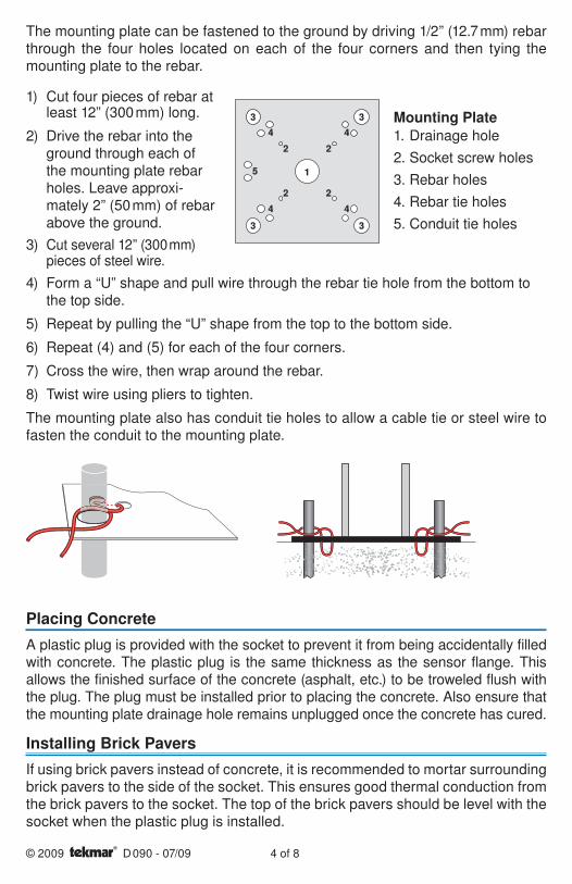
The mounting plate can be fastened to the ground by driving 1/2” (12.7 mm) rebar through the four holes located on each of the four corners and then tying the mounting plate to the rebar.
Mounting Plate1. Drainage hole
2. Socket screw holes
3. Rebar holes
4. Rebar tie holes
5. Conduit tie holes
3 3
3 3
4 4
4 4
5
2
1
2
2 2
4) Form a “U” shape and pull wire through the rebar tie hole from the bottom to the top side.
5) Repeat by pulling the “U” shape from the top to the bottom side.
6) Repeat (4) and (5) for each of the four corners.
7) Cross the wire, then wrap around the rebar.
8) Twist wire using pliers to tighten.
The mounting plate also has conduit tie holes to allow a cable tie or steel wire to fasten the conduit to the mounting plate.
Placing Concrete
A plastic plug is provided with the socket to prevent it from being accidentally filled with concrete. The plastic plug is the same thickness as the sensor flange. This allows the finished surface of the concrete (asphalt, etc.) to be troweled flush with the plug. The plug must be installed prior to placing the concrete. Also ensure that the mounting plate drainage hole remains unplugged once the concrete has cured.
Installing Brick Pavers
If using brick pavers instead of concrete, it is recommended to mortar surrounding brick pavers to the side of the socket. This ensures good thermal conduction from the brick pavers to the socket. The top of the brick pavers should be level with the socket when the plastic plug is installed.
1) Cut four pieces of rebar at least 12” (300 mm) long.
2) Drive the rebar into the ground through each of the mounting plate rebar holes. Leave approxi-mately 2” (50 mm) of rebar above the ground.
3) Cut several 12” (300 mm) pieces of steel wire.

5 of 8 © 2009 D 090 - 07/09
Install the Sensor and Cable
When the snow melt surface is finished, remove the plastic plug from the socket and fish the cable through the conduit until there is only 6 to 12” (150 to 300 mm) of cable between the sensor and conduit. Loop this remaining extra wire in a loose coil so as to not twist it, and place it, and the sensor into the socket. Secure the sensor to the socket with the four screws provided, making sure the “O” ring is in place and properly seated.
Replacing old 090 or 094
Current versions of the Snow / Ice socket 091 use #6-32 screws. Previous versions of the 091 used smaller #4-40 screws. When replacing an 090 or 094, both sets of screws are provided. It is recommended to try the smaller screws first to avoid cross threading.
Salt and Brine Contamination
The performance of the snow / ice sensor water detection can be compromised when exposed to de-icing agents such as road salt, magnesium chloride, or calcium chloride. These contaminants can permanently damage the sensor. It is recommended to locate the sensor away from areas exposed to these deicing agents when at all possible. Locations to avoid could include tire track areas or areas close to a curb where traveling vehicles may splash contaminated water on to the sensor.
Maintenance
The Snow / Ice Sensor is installed in a hostile environment. Accumulation of dirt, salty grime, etc., on its surface will inhibit proper water detection. It should be checked on a regular basis and, when necessary, cleaned. Before cleaning, the control power should be shut off to prevent the control from entering the snow melt mode. Next, use a soft bristle brush and warm soapy water to clean the sensor surface. Do not use a steel wire brush as this will damage the sensor. Then use a paper towel to thoroughly dry the sensor surface. After cleaning, re-power the control and push the test button to cycle the control through the test routine.
STEP THREE — — WIRING THE SENSORElectrical Connections
The snow / ice sensor cable has 5 wires: Red, Black, Blue, Yellow, and Brown. The wires connect to the respective Red, Black, Blue, Yellow and Brown terminals on the Snow Detector & Melting Control.
© 2009 D 090 - 07/09 6 of 8
Temperature Resistance°F °C-49 -45 472,000
-40 -40 337,000
-31 -35 243,000
-22 -30 177,000
-13 -25 130,000
-4 -20 97,000
Temperature Resistance°F °C5 -15 72,900
14 -10 55,300
23 -5 42,300
32 0 32,600
41 5 25,400
50 10 19,900
Temperature Resistance°F °C59 15 15,700
68 20 12,500
77 25 10,000
86 30 8,060
95 35 6,530
104 40 5,330
Testing and Troubleshooting
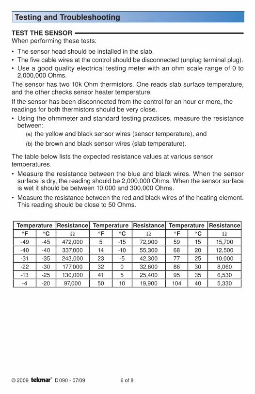
TEST THE SENSORWhen performing these tests:
The sensor head should be installed in the slab.
The five cable wires at the control should be disconnected (unplug terminal plug).
Use a good quality electrical testing meter with an ohm scale range of 0 to 2,000,000 Ohms.
The sensor has two 10k Ohm thermistors. One reads slab surface temperature, and the other checks sensor heater temperature.
If the sensor has been disconnected from the control for an hour or more, the readings for both thermistors should be very close.
Using the ohmmeter and standard testing practices, measure the resistance between:
(a) the yellow and black sensor wires (sensor temperature), and
(b) the brown and black sensor wires (slab temperature).
The table below lists the expected resistance values at various sensor temperatures.
Measure the resistance between the blue and black wires. When the sensor surface is dry, the reading should be 2,000,000 Ohms. When the sensor surface is wet it should be between 10,000 and 300,000 Ohms.
Measure the resistance between the red and black wires of the heating element. This reading should be close to 50 Ohms.
•
•
•
•
•
•
7 of 8 © 2009 D 090 - 07/09
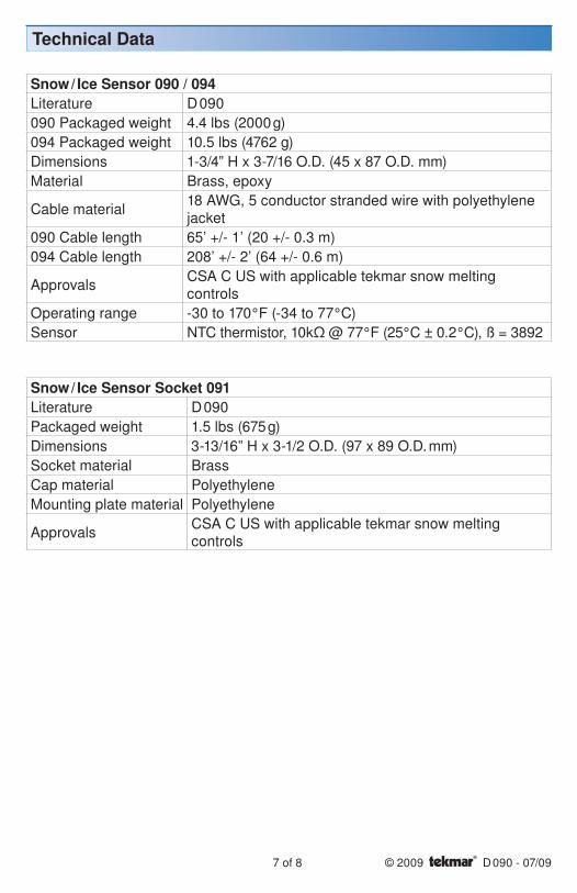
Snow / Ice Sensor 090 / 094Literature D 090
090 Packaged weight 4.4 lbs (2000 g)
094 Packaged weight 10.5 lbs (4762 g)
Dimensions 1-3/4” H x 3-7/16 O.D. (45 x 87 O.D. mm)
Material Brass, epoxy
Cable material18 AWG, 5 conductor stranded wire with polyethylene jacket
090 Cable length 65’ +/- 1’ (20 +/- 0.3 m)
094 Cable length 208’ +/- 2’ (64 +/- 0.6 m)
ApprovalsCSA C US with applicable tekmar snow melting controls
Operating range -30 to 170°F (-34 to 77°C)
Sensor NTC thermistor, 10kΩ @ 77°F (25°C ± 0.2°C), ß = 3892
Snow / Ice Sensor Socket 091Literature D 090
Packaged weight 1.5 lbs (675 g)
Dimensions 3-13/16” H x 3-1/2 O.D. (97 x 89 O.D. mm)
Socket material Brass
Cap material Polyethylene
Mounting plate material Polyethylene
ApprovalsCSA C US with applicable tekmar snow melting controls
Technical Data
All specifications are subjectto change without notice
8 of 8 D 090 - 07/09
tekmar Control Systems Ltd., Canadatekmar Control Systems, Inc., U.S.A.Head Office: 5100 Silver Star RoadVernon, B.C. Canada V1B 3K4(250) 545-7749 Fax. (250) 545-0650Web Site: www.tekmarcontrols.com
Product design, software and literatureare Copyright © 2009 by:tekmar Control Systems Ltd. and tekmarControl Systems, Inc.
Limited Warranty The liability of tekmar under this warranty is limited. The Purchaser, by taking receipt of any tekmar product (“Product”), acknowledges the terms of the Limited Warranty in effect at the time of such Product sale and acknowledges that it has read and understands same.
The tekmar Limited Warranty to the Purchaser on the Products sold hereunder is a manufacturer’s pass-through warranty which the Purchaser is authorized to pass through to its customers. Under the Limited Warranty, each tekmar Product is warranted against defects in workmanship and materi-als if the Product is installed and used in compliance with tekmar’s instructions, ordinary wear and tear excepted. The pass-through warranty period is for a period of twenty-four (24) months from the production date if the Product is not installed during that period, or twelve (12) months from the docu-mented date of installation if installed within twenty-four (24) months from the production date.
The liability of tekmar under the Limited Warranty shall be limited to, at tekmar’s sole discretion: the cost of parts and labor provided by tekmar to repair defects in materials and / or workmanship of the defective product; or to the exchange of the defective product for a warranty replacement product; or to the granting of credit limited to the original cost of the defective product, and such repair, exchange or credit shall be the sole remedy available from tekmar, and, without limiting the foregoing in any way, tekmar is not respon-sible, in contract, tort or strict product liability, for any other losses, costs, expenses, inconveniences, or damages, whether direct, indirect, special, secondary, incidental or consequential, arising from ownership or use of the product, or from defects in workmanship or materials, including any liability for fundamental breach of contract.
The pass-through Limited Warranty applies only to those defective Products returned to tekmar during the warranty period. This Limited Warranty does not cover the cost of the parts or labor to remove or transport the defective Product, or to reinstall the repaired or replacement Product, all such costs and expenses being subject to Purchaser’s agreement and warranty with its customers.
Any representations or warranties about the Products made by Purchaser to its customers which are differ-ent from or in excess of the tekmar Limited Warranty are the Purchaser’s sole responsibility and obligation. Purchaser shall indemnify and hold tekmar harmless from and against any and all claims, liabilities and damages of any kind or nature which arise out of or are related to any such representations or warranties by Purchaser to its customers.
The pass-through Limited Warranty does not apply if the returned Product has been damaged by negli-gence by persons other than tekmar, accident, fire, Act of God, abuse or misuse; or has been damaged by modifications, alterations or attachments made subsequent to purchase which have not been authorized by tekmar; or if the Product was not installed in compliance with tekmar’s instructions and / or the local codes and ordinances; or if due to defective installation of the Product; or if the Product was not used in compli-ance with tekmar’s instructions.
THIS WARRANTY IS IN LIEU OF ALL OTHER WARRANTIES, EXPRESS OR IMPLIED, WHICH THE GOV-ERNING LAW ALLOWS PARTIES TO CONTRACTUALLY EXCLUDE, INCLUDING, WITHOUT LIMITA-TION, IMPLIED WARRANTIES OF MERCHANTABILITY AND FITNESS FOR A PARTICULAR PURPOSE, DURABILITY OR DESCRIPTION OF THE PRODUCT, ITS NON-INFRINGEMENT OF ANY RELEVANT PATENTS OR TRADEMARKS, AND ITS COMPLIANCE WITH OR NON-VIOLATION OF ANY APPLICABLE ENVIRONMENTAL, HEALTH OR SAFETY LEGISLATION; THE TERM OF ANY OTHER WARRANTY NOT HEREBY CONTRACTUALLY EXCLUDED IS LIMITED SUCH THAT IT SHALL NOT EXTEND BEYOND TWENTY-FOUR (24) MONTHS FROM THE PRODUCTION DATE, TO THE EXTENT THAT SUCH LIMITA-TION IS ALLOWED BY THE GOVERNING LAW.
Product Warranty Return Procedure All Products that are believed to have defects in workmanship or materials must be returned, together with a written description of the defect, to the tekmar Representative assigned to the territory in which such Product is located. If tekmar receives an inquiry from someone other than a tekmar Representative, including an inquiry from Purchaser (if not a tekmar Representative) or Purchaser’s customers, regarding a potential warranty claim, tekmar’s sole obligation shall be to provide the address and other contact information regarding the appropriate Representative.
Limited Warranty and Product Return Procedure