Embed Size (px)
Citation preview

DANIEL “PT” LIQUID TURBINE METERS 3" THROUGH 24" SIZES
__________________________________________
INSTALLATION AND MAINTENANCE INSTRUCTIONS
DANIEL MEASUREMENT AND CONTROL, INC.AN EMERSON PROCESS MANAGEMENT COMPANY
HOUSTON, TEXAS
Part Number 3-9008-011 Revision F
AUGUST 2009


IMPORTANT INSTRUCTIONS
Daniel Measurement and Control, Inc. (Daniel) designs, manufactures and tests its products to meetmany national and international standards. Because these instruments are sophisticated technicalproducts, you must properly install, use and maintain them to ensure they continue to operate withintheir normal specifications. The following instructions must be adhered to and integrated into yoursafety program when installing, using and maintaining Daniel products.
• Read all instructions prior to installing, operating and servicing the product. If thisinstruction manual is not the correct manual, call 1-713-827-6314 (24-hour response numberfor both Service and Sales Support) and the requested manual will be provided. Save thisinstruction manual for future reference.
• If you do not understand any of the instructions, contact your Daniel representative forclarification.
• Follow all warnings, cautions and instructions marked on and supplied with the product.• Inform and educate your personnel in the proper installation, operation and maintenance of
the product.• Install your equipment as specified in the installation instructions of the appropriate
instruction manual and per applicable local and national codes. Connect all products to theproper electrical and pressure sources.
• To ensure proper performance, use qualified personnel to install, operate, update, programand maintain the product.
• When replacement parts are required, ensure that qualified people use replacement partsspecified by the manufacturer. Unauthorized parts and procedures can affect the product'sperformance and place the safe operation of your process at risk. Look-alike substitutionsmay result in fire, electrical hazards or improper operation.
• Ensure that all equipment doors are closed and protective covers are in place, except whenmaintenance is being performed by qualified persons, to prevent personal injury.
• ALWAYS READ AND FOLLOW THE DANIEL “PT” LIQUID TURBINE METERMANUAL AND ALL PRODUCT WARNINGS AND INSTRUCTIONS.
• Use of this equipment for any purpose other than its intended purpose may result in propertydamage and/or serious personal injury or death.
• Before opening the flameproof enclosure in a flammable atmosphere, the electrical circuitsmust be interrupted.


DANIEL “PT” LIQUID TURBINE METERS AUG 2009
PREFACE i
DANIEL “PT” LIQUID TURBINE METERSINSTALLATION AND MAINTENANCE INSTRUCTIONS
NOTICE
THE CONTENTS OF THIS PUBLICATION ARE PRESENTED FOR INFORMATIONAL PURPOSES ONLY, AND
WHILE EVERY EFFORT HAS BEEN MADE TO ENSURE THEIR ACCURACY, THEY ARE NOT TO BE
CONSTRUED AS WARRANTIES OR GUARANTEES, EXPRESSED OR IMPLIED, REGARDING THE
PRODUCTS OR SERVICES DESCRIBED HEREIN OR THEIR USE OR APPLICABILITY. ALL SALES ARE
GOVERNED BY DANIEL’S TERMS AND CONDITIONS, WHICH ARE AVAILABLE UPON REQUEST. WE
RESERVE THE RIGHT TO MODIFY OR IMPROVE THE DESIGNS OR SPECIFICATIONS OF SUCH PRODUCTS
AT ANY TIME.
DANIEL DOES NOT ASSUME RESPONSIBILITY FOR THE SELECTION, USE OR MAINTENANCE OF ANY
PRODUCT. RESPONSIBILITY FOR PROPER SELECTION, USE AND MAINTENANCE OF ANY DANIEL
PRODUCT REMAINS SOLELY WITH THE PURCHASER AND END-USER.
TO THE BEST OF DANIEL’S KNOWLEDGE THE INFORM ATION HEREIN IS COM PLETE AND
ACCURATE. DANIEL MAKES NO WARRANTIES, EXPRESSED OR IMPLIED, INCLUDING THE
IMPLIED WARRANTIES OF MERCHANTABILITY AND FITNESS FOR A PARTICULAR PURPOSE WITH
RESPECT TO THIS MANUAL AND, IN NO EVENT, SHALL DANIEL BE LIABLE FOR ANY INCIDENTAL,
PUNITIVE, SPECIAL OR CONSEQUENTIAL DAMAGES INCLUDING, BUT NOT LIMITED TO, LOSS OF
PRODUCTION, LOSS OF PROFITS, LOSS OF REVENUE OR USE AND COSTS INCURRED INCLUDING
WITHOUT LIMITATION FOR CAPITAL, FUEL AND POWER, AND CLAIMS OF THIRD PARTIES.
PRODUCT NAMES USED HEREIN ARE FOR MANUFACTURER OR SUPPLIER IDENTIFICATION ONLY AND
MAY BE TRADEMARKS/REGISTERED TRADEMARKS OF THESE COMPANIES.
DANIEL AND THE DANIEL LOGO ARE REGISTERED TRADEMARKS OF DANIEL INDUSTRIES, INC. THE
EMERSON LOGO IS A TRADEMARK AND SERVICE MARK OF EMERSON ELECTRIC CO.
COPYRIGHT © 2009
BY DANIEL MEASUREMENT AND CONTROL, INC.
HOUSTON, TEXAS, U.S.A.
All rights reserved. No part of this work may be reproduced or
copied in any form or by any means - graphic, electronic or
mechanical - without first receiving the written permission of
Daniel Measurement and Control, Inc., Houston, Texas, U.S.A.

AUG 2009 DANIEL “PT” LIQUID TURBINE METERS
PREFACEii
WARRANTY
1. LIMITED WARRANTY: Subject to the limitations contained in Section 2 herein, Daniel Measurement & Control,
Inc. (“Daniel”) warrants that the licensed firmware embodied in the Goods will execute the programming instructions
provided by Daniel, and that the Goods manufactured by Daniel will be free from defects in materials or workmanship
under normal use and care and Services will be performed by trained personnel using proper equipment and
instrumentation for the particular Service provided. The foregoing warranties will apply until the expiration of the
applicable warranty period. Goods are warranted for twelve (12) months from the date of initial installation or eighteen
(18) months from the date of shipment by Daniel, whichever period expires first. Consumables and Services are
warranted for a period of 90 days from the date of shipment or completion of the Services. Products purchased by Daniel
from a third party for resale to Buyer (“Resale Products”) shall carry only the warranty extended by the original
manufacturer. Buyer agrees that Daniel has no liability for Resale Products beyond making a reasonable commercial
effort to arrange for procurement and shipping of the Resale Products. If Buyer discovers any warranty defects and
notifies Daniel thereof in writing during the applicable warranty period, Daniel shall, at its option, correct any errors that
are found by Daniel in the firmware or Services or repair or replace F.O.B. point of manufacture that portion of the
Goods or firmware found by Daniel to be defective, or refund the purchase price of the defective portion of the
Goods/Services. All replacements or repairs necessitated by inadequate maintenance, normal wear and usage, unsuitable
power sources or environmental conditions, accident, misuse, improper installation, modification, repair, use of
unauthorized replacement parts, storage or handling, or any other cause not the fault of Daniel are not covered by this
limited warranty, and shall be at Buyer’s expense. Daniel shall not be obligated to pay any costs or charges incurred by
Buyer or any other party except as may be agreed upon in writing in advance by Daniel. All costs of dismantling,
reinstallation and freight and the time and expenses of Daniel’s personnel and representatives for site travel and diagnosis
under this warranty clause shall be borne by Buyer unless accepted in writing by Daniel. Goods repaired and parts
replaced by Daniel during the warranty period shall be in warranty for the remainder of the original warranty period or
ninety (90) days, whichever is longer. This limited warranty is the only warranty made by Daniel and can be amended
only in a writing signed by Daniel. THE WARRANTIES AND REMEDIES SET FORTH ABOVE ARE EXCLUSIVE.
THERE ARE NO REPRESENTATIONS OR WARRANTIES OF ANY KIND, EXPRESS OR IMPLIED, AS TO
MERCHANTABILITY, FITNESS FOR PARTICULAR PURPOSE OR ANY OTHER MATTER WITH RESPECT
TO ANY OF THE GOODS OR SERVICES. Buyer acknowledges and agrees that corrosion or erosion of materials
is not covered by this warranty.
2. LIMITATION OF REMEDY AND LIABILITY: DANIEL SHALL NOT BE LIABLE FOR DAMAGES CAUSED
BY DELAY IN PERFORMANCE. THE REMEDIES OF BUYER SET FORTH IN THIS AGREEMENT ARE
EXCLUSIVE. IN NO EVENT, REGARDLESS OF THE FORM OF THE CLAIM OR CAUSE OF ACTION
(WHETHER BASED IN CONTRACT, INFRINGEMENT, NEGLIGENCE, STRICT LIABILITY, OTHER TORT OR
OTHERWISE), SHALL DANIEL’S LIABILITY TO BUYER AND/OR ITS CUSTOMERS EXCEED THE PRICE
TO BUYER OF THE SPECIFIC GOODS MANUFACTURED OR SERVICES PROVIDED BY DANIEL GIVING
RISE TO THE CLAIM OR CAUSE OF ACTION. BUYER AGREES THAT IN NO EVENT SHALL DANIEL’S
LIABILITY TO BUYER AND/OR ITS CUSTOMERS EXTEND TO INCLUDE INCIDENTAL, CONSEQUENTIAL
OR PUNITIVE DAMAGES. THE TERM “CONSEQUENTIAL DAMAGES” SHALL INCLUDE, BUT NOT BE
LIMITED TO, LOSS OF ANTICIPATED PROFITS, REVENUE OR USE AND COSTS INCURRED INCLUDING
WITHOUT
DANIEL “PT” LIQUID TURBINE METERS AUG 2009
TABLE OF CONTENTS iii
TABLE OF CONTENTS
1.0 DIMENSIONS AND SPECIFICATIONS . . . . . . . . . . . . . . . . . . . . . . . . . . . . . . . . . . . 1-1
2.0 INSTALLATION AND INITIAL OPERATION . . . . . . . . . . . . . . . . . . . . . . . . . . . . . 2-1
3.0 TURBINE METER INSTRUMENTATION . . . . . . . . . . . . . . . . . . . . . . . . . . . . . . . . . 3-1
4.0 GENERAL INFORMATION . . . . . . . . . . . . . . . . . . . . . . . . . . . . . . . . . . . . . . . . . . . . 4-1
5.0 3" THROUGH 24" PT METER - METER DISASSEMBLY . . . . . . . . . . . . . . . . . . . . 5-1
6.0 3" THROUGH 24" PT METER - METER ASSEMBLY . . . . . . . . . . . . . . . . . . . . . . . 6-1
7.0 INSPECTION . . . . . . . . . . . . . . . . . . . . . . . . . . . . . . . . . . . . . . . . . . . . . . . . . . . . . . . . 7-1

AUG 2009 DANIEL “PT” LIQUID TURBINE METERS
TABLE OF CONTENTSiv
This page intentionally left blank.
DANIEL “PT” LIQUID TURBINE METERS AUG 2009
SECTION 1 1-1
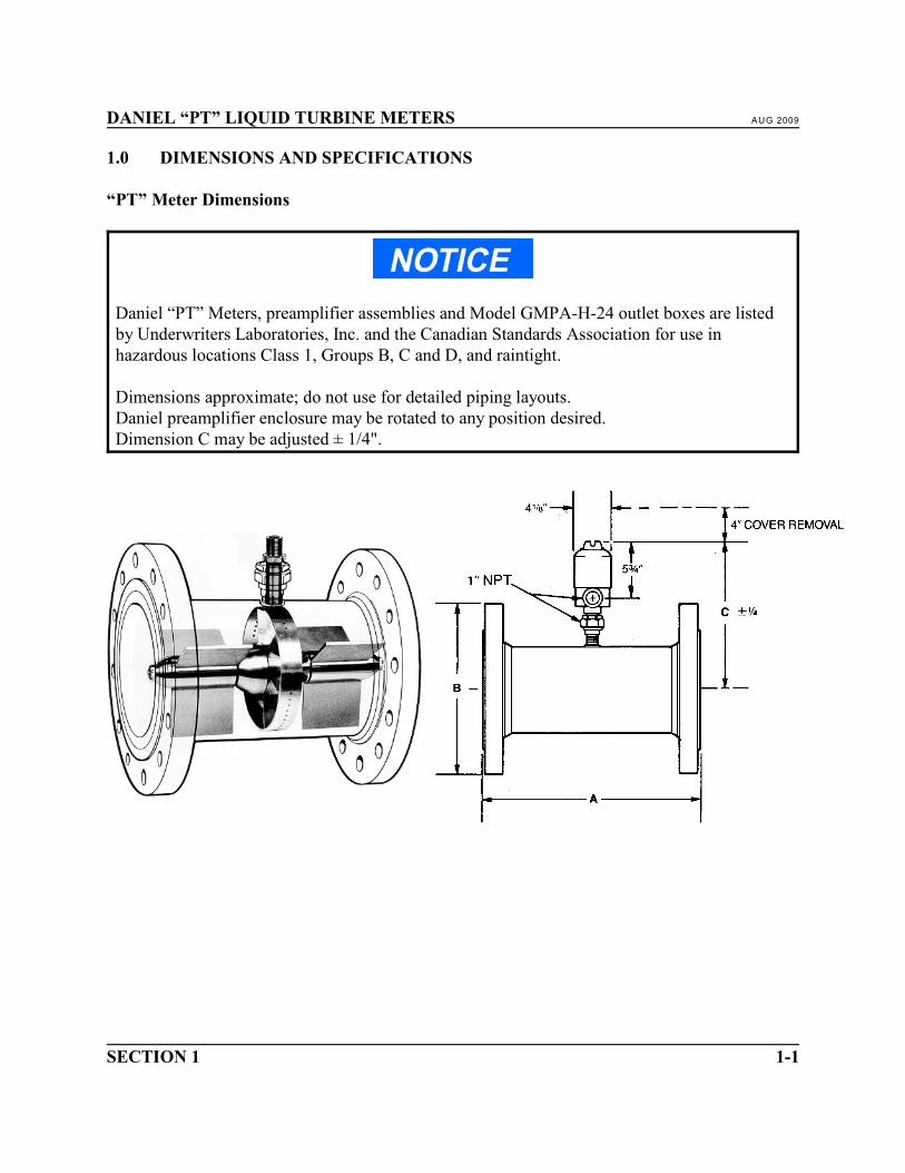
1.0 DIMENSIONS AND SPECIFICATIONS
“PT” Meter Dimensions
Daniel “PT” Meters, preamplifier assemblies and Model GMPA-H-24 outlet boxes are listedby Underwriters Laboratories, Inc. and the Canadian Standards Association for use inhazardous locations Class 1, Groups B, C and D, and raintight.
Dimensions approximate; do not use for detailed piping layouts.Daniel preamplifier enclosure may be rotated to any position desired.Dimension C may be adjusted ± 1/4".

AUG 2009 DANIEL “PT” LIQUID TURBINE METERS
DIMENSIONS AND SPECIFICATIONS1-2
DIMENSIONSIN INCHESWEIGHTIN POUNDS
NOMINAL LINE SIZE
3" 4" 6" 8" 10" 12" 16" 18" 20" 24"
150#ANSI
A 10 12 14 16 20 24 32 36 40 48
B 7 1/2 9 11 13 1/2 16 19 23 1/2 25 27 1/2 32
C 11 13/16 12 1/4 13 5/16 14 1/4 15 5/16 16 1/4 18 1/2 19 3/8 20 1/2 22 1/8
WEIGHT* 28 45 72 105 190 335 530 720 940 1,435
300#ANSI
A 10 12 14 16 20 24 32 36 40 48
B 8 1/4 10 12 1/2 15 17 1/2 20 1/2 25 1/2 28 30 1/2 36
C 11 13/16 12 1/4 13 5/16 14 1/4 15 5/16 16 1/4 18 1/2 19 3/8 20 1/2 22 1/8
WEIGHT* 30 60 112 150 270 440 860 1,150 1,400 2,150
400#ANSI
A 10 12 14 16 20 24 32 36 40 48
B 8 1/4 10 12 1/2 15 17 1/2 20 1/2 25 1/2 28 30 1/2 36
C 11 13/16 12 1/4 13 5/16 14 1/2 15 5/16 16 1/4 18 1/2 19 3/8 20 1/2 22 1/8
WEIGHT* 42 68 120 180 290 470 950 1,200 1,420 2,300
600#ANSI
A 10 12 14 16 20 24 32 36 40 48
B 8 1/4 10 3/4 14 16 1/2 20 22 27 29 1/4 32 37
C 11 13/16 12 1/4 13 5/16 15 16 1/16 17 18 1/2 19 3/8 20 1/2 22 1/8
WEIGHT* 42 88 205 300 450 580 1,250 1,650 2,100 3,200
900#ANSI
A 10 12 14 16 20 24 - - - -
B 9 1/2 11 1/2 15 18 1/2 21 1/2 22 - - - -
C 11 13/16 13 13 5/16 15 16 1/16 17 - - - -
WEIGHT* 78 125 255 400 625 850 - - - -
Above dimensions subject to change without notice.* Weight is without preamplifier assembly. Add 4 lbs. for each preamplifier assembly.

DANIEL “PT” LIQUID TURBINE METERS AUG 2009
SECTION 1 1-3
Specifications - “PT” Meters
“PT” Meter, rim and blade type, when installed with meter tube and straightening sections andcalibrated on water.
Linearity:3" and larger:±0.25% normal linearity±0.5% over extended minimum to extended maximum flow range.±0.15% premium linearity±0.10% premium + linearity±0.07% premium ++ linearity
Repeatability:±0.02% at any point throughout the extended minimum to extended maximum flow range.
Pressure Drop:At maximum flow of normal flow range on water 4 psi.
Pressure Range:ANSI 150-1500# depending upon size
Viscosity:High viscosities will reduce flow range of meter. Consult Daniel Measurement engineers.
Pickup Coil:Nominal open circuit peak to peak voltage output:
BLADE RIMMEDMinimum flow 4.0v 5.0vMaximum flow 0.3v 0.1v

AUG 2009 DANIEL “PT” LIQUID TURBINE METERS
DIMENSIONS AND SPECIFICATIONS1-4
MATERIALS OF CONSTRUCTION
ITEM STANDARD OPTIONAL
Meter Body 304SS 316SS
Flanges (Slip on) Carbon Steel 304SS or 316SS
Suspension 304SS 316SS
Rotor Blades (Rim Type) 304SS 316SS
Rotor Blades (Blade Type)* 430SS Nickel 200*
Sleeve Bearings Cemented Tungsten Carbide ^
Journal Bearings Cemented Tungsten Carbide ^
Rotor Hub 1"-6" 8"-12" 16"-24"
430SS430SS
430SS and 7075AL
316SS or 304SS430SS and 7075AL
^
Rotor Rim 2"-4" 6"-24"
316SS304SS
^316SS
Rim Buttons Hi Mu 80 ^
Cones 304SS 316SS
Shaft 17-4 PH Heat Treated Stainless Steel
* Recommended for salt water service; blade type meters with 316SS body, 316SS suspension, 316SS cones andNickel 200 blades.
^ No option available.NOTE: Consult Daniel Measurement engineers for unique applications.
METER TEM PERATURE LIMITS
SIZE
Rotor Hub Materials
304SS or 316SS 430SS
3" thru 6" -50°F to +250°F* -50°F to +800°F
8" thru 12" -50°F to +800°F -50°F to +800°F
16" thru 24" -50°F to +700°F -50°F to +800°F
* Standard materials (All others by special design)

DANIEL “PT” LIQUID TURBINE METERS AUG 2009
SECTION 1 1-5
STANDARD “PT” METER PULSES PER UNIT VOLUME
METER SIZE DESIGN PULSES
PER 42 GALLON
BARREL
DESIGN PULSES
PER GALLON
DESIGN PULSES
PER M 3
DESIGN
OUTPUT FREQ.
AT MAX. FLOW
(HZ.)
3" BT 2,016 48.0 12,682 520
3" RT 4,620 110 29,062 1,192
4" BT 1,000 23.8 6,290 496
4" RT 3,000 71.4 18,864 1,487
6" BT 235 5.6 1,478 271
6" RT 1,000 23.8 6,290 1,150
8" RT 500 11.9 3,145 1,031
10" RT 250 6.0 1,572 800
12" RT 200 4.8 1,258 960
16" RT 100 2.4 629 720
18" RT 100 2.4 629 964
20" RT 100 2.4 629 1,180
24" RT 100 2.4 629 1,600
BT = Blade Type RT = Rim Type
Output frequency is nominal for maximum normal flow. Output frequency is essentially linearwith flow so that frequency for other flow rates may be determined by ratio of flow tomaximum flow rate.

AUG 2009 DANIEL “PT” LIQUID TURBINE METERS
DIMENSIONS AND SPECIFICATIONS1-6
LIQUID CAPACITY TABLE - NORMAL FLOW RANGE
METER
SIZE
NORM AL FLOW RANGE
MINIMUM LINEAR MAXIMUM LINEAR
GPM BPH BPD M PH GPM BPH BPD M PH3 3
3" 55 79 1,886 12.5 650 929 22,286 148
4" 85 121 2,914 19.3 1,250 1,786 42,857 284
6" 240 343 8,229 55 2,900 4,143 99,429 659
8" 475 679 16,286 108 5,200 7,429 178,286 1,181
10" 800 1,143 27,429 182 8,000 11,429 274,286 1,817
12" 1,330 1,900 45,600 302 12,000 17,143 411,429 2,725
16" 2,140 3,057 73,371 486 18,000 25,714 617,143 4,088
18" 2,860 4,086 98,057 650 24,100 34,429 826,286 5,474
20" 3,500 5,000 120,000 795 29,500 42,143 1,011,429 6,700
24" 4,700 6,714 161,143 1,067 40,000 57,143 1,371,429 9,085
NOTES:1. Stated specifications are based on water at 60°F, with a specific gravity of 1.0 and a viscosity of 1.0 centistokes.2. Meters should be adequately protected from pressure pulsations and excessive surges.3. Generally, the PT Turbine should not be used in continuous service from the normal maximum to the extended
maximum flow rates. Consult Daniel Measurement engineers for proper sizing and consideration.4. All specifications are subject to change without notice as part of a continuing program of product improvement.5. Bi-directional meters have a linear flow range as stated in one direction of flow. The minimum linear flow rate
in the reverse direction is 20% of its normal maximum linear flow rate.

DANIEL “PT” LIQUID TURBINE METERS AUG 2009
SECTION 1 1-7
LIQUID CAPACITY TABLE - EXTENDED FLOW RANGE
METER
SIZE
MINIMUM EXTENDED
FLOW RANGE
MAXIMUM EXTENDED
FLOW RANGE
GPM BPH BPD M PH GPM BPH BPD M PH3 3
3" 36 51 1,234 8.18 800 1,143 27,429 182
4" 55 79 1,886 12.5 1,500 2,143 51,429 341
6" 156 223 5,349 35.4 3,600 5,143 123,429 818
8" 389 556 13,337 88.4 6,400 9,143 219,429 1,454
10" 664 949 22,766 151 9,800 14,000 336,000 2,226
12" 1,183 1,690 40,560 269 15,000 21,429 514,286 3,407
16" 1,400 2,000 48,000 318 22,500 32,143 771,429 5,110
18" 1,900 2,714 65,143 432 30,000 42,857 1,028,571 6,814
20" 2,350 3,357 80,571 534 36,900 52,714 1,265,143 8,381
24" 3,200 4,571 109,714 727 51,400 73,429 1,762,286 11,674
NOTES:1. Stated specifications are based on water at 60°F, with a specific gravity of 1.0 and a viscosity of 1.0 centistokes.2. Meters should be adequately protected from pressure pulsations and excessive surges.3. Generally, the PT Turbine should not be used in continuous service from the normal maximum to the extended
maximum flow rates. Consult Daniel Measurement engineers for proper sizing and consideration.4. All specifications are subject to change without notice as part of a continuing program of product improvement.5. Bi-directional meters have a linear flow range as stated in one direction of flow. The minimum linear flow rate
in the reverse direction is 20% of its normal maximum linear flow rate.
Approvals
XIHL outlet box certification: EExd IIB T6GUB2 outlet box certification: EExd IIB T6
“CE” marked units comply with the following directives:Pressure Equipment Directive 97/23/ECElectroMagnetic Compatibility Directive 89/336/EECATEX Directive 94/9/EC

AUG 2009 DANIEL “PT” LIQUID TURBINE METERS
DIMENSIONS AND SPECIFICATIONS1-8
This page intentionally left blank.

DANIEL “PT” LIQUID TURBINE METERS AUG 2009
SECTION 2 2-1
2.0 INSTALLATION AND INITIAL OPERATION
Installation
On installations which are required to comply with the European Union Pressure EquipmentDirective (PED) 97/23/EC, it is the responsibility of the end user to ensure that all Essential SafetyRequirements of this directive are met.
The “PT” Meter has high resistance to shock while it is operating because of the supporting effectof the fluid. This resistance is greatly reduced when the meter is out of the line or inoperative.
MECHANICAL EQUIPMENT DAMAGE
Great care should be taken to prevent shock.
Failure to handle the meter with care during installation, removal or shipment may result indamage to the meter.
If sealing compound is used on piping during meter installation, use it sparingly to avoid foulingmeter parts. Absolute cleanliness of meter internals is important, and precautions should be takento prevent entry of foreign matter. Use a strainer upstream of the meter tube section. Anothercommon cause of meter malfunction, due to fouling of the rotor, is objects left inside the pipeline.
MECHANICAL EQUIPMENT DAMAGE
Flush and clean piping system prior to meter installation.
Failure to maintain absolute cleanliness of meter components may result in damage andimproper meter operation.

AUG 2009 DANIEL “PT” LIQUID TURBINE METERS
INSTALLATION AND INITIAL OPERATION2-2
It is the responsibility of the end user to install the fitting in a well designed piping system taking dueregard of the following.
• Internal/external pressure• Ambient and operational temperatures• Static pressure and mass of contents in operating and test conditions• Traffic, wind and earth loading• Reaction forces and moments which result from supports, attachments, piping, etc.• Corrosion, erosion, fatigue, etc.• Decomposition of unstable fluids• Possible damage from external fire
Daniel Method of Aligning Meter Tube Flange to “PT” Meter Flange
Internal alignment throughout the metering section is vital to prevent offsets, steps or gasketprotrusion within the bore which could cause disturbance to the flow pattern. Alignment isaccomplished by dowel-pinning.
On all Daniel raised face flanged “PT” Meters and “PT” Meter Tubes three knock-out dowel pinholes are drilled in each flange for alignment of the bore of the meter to the bore of the meter tube.
On ANSI Class 150 lb. and 300 lb. meters and meter tubes where the dowel pin holes are locatedtangent to the raised face, female face-type gaskets are used.
On ANSI Class 400 lb. through 2500 lb. meters and meter tubes where the dowel pin holes arelocated beyond the inner bolt circle, series-type gaskets are used.
Care should be taken not to allow the gasket to protrude into the flow stream upon installation.
It is recommended that dowel pins be removed after flange bolt-up and grease packed in the holesto prevent rust.

DANIEL “PT” LIQUID TURBINE METERS AUG 2009
SECTION 2 2-3
Meter Tubes
Experience has confirmed the necessity of adequate upstream and downstream straight pipe adjacentto the meter. Daniel “PT” Meter Tubes and Straightening Vanes are fabricated to proper dimensionsand tolerances to assure that the flow pattern through the meter is undisturbed by pipingconfiguration.
The table of recommended dimensions for “PT” Meter Tubes takes into account piping design,where swirls and disturbances are introduced by fittings, valves, etc., adjacent to the meter tubesection. The recommended lengths shown (with a straightening vane) are for the maximum flowdisturbance conditions. The illustrations show proper positioning of straightening vanes.
The vanes may be eliminated if adequate straight pipe exists upstream and downstream. For pipelengths not requiring vanes, see Daniel Catalog Section “D”, AGA Report No.3, the ASME PowerTest Code, or API Standard 2534.

AUG 2009 DANIEL “PT” LIQUID TURBINE METERS
INSTALLATION AND INITIAL OPERATION2-4
Meter Tubes with Straightening Vanes
MINIMUM RECOM MENDED DIMENSIONS
NOMINAL LINE SIZE S U A D OA
3" 1' - 0" 2' - 0" 10" 1' - 3" 5' - 1"
4" 1' - 0" 2' - 8" 1' - 0" 1' - 8" 6' - 4"
6" 1' - 6" 3' - 6" 1' - 2" 2' - 6" 8' - 8"
8" 2' - 0" 4' - 8" 1' - 4" 3' - 4" 11' - 4"
10" 2' - 6" 5' - 10" 1' - 8" 4' - 2" 14' - 2"
12" 3' - 0" 7' - 0" 2' - 0" 5' - 0" 17' - 0"
16" 4' - 0" 9' - 4" 2' - 6" 6' - 8" 22' - 8"
18" 4' - 6" 10' - 6" 3' - 0" 7' - 6" 25' - 6"
20" 5 - 0" 11' - 8" 3' - 4" 8' - 4" 28' - 4"
24" 6' - 0" 14' - 0" 4' - 0" 10' - 0" 34' - 0"

DANIEL “PT” LIQUID TURBINE METERS AUG 2009
SECTION 2 2-5
Meter Tubes can be supplied with any type of line connection, in special materials and to anyspecified length.
Illustrations show a two-section meter tube with a line type vane and a three-section tube with aflange type vane. It is recommended that the flange type be used, as it can be easily removed forinspection; and, by using the three-section tube with the spacer and jack screws, the meter can alsobe easily removed from the line. The Illustration shows flanged outer ends. Other end connectionsmay be supplied.
Daniel recommends installation of strainers upstream of the meter. Flow control valves shouldbe located downstream of the meter.

AUG 2009 DANIEL “PT” LIQUID TURBINE METERS
INSTALLATION AND INITIAL OPERATION2-6
Back Pressure
Back Pressure is the operating pressure measured five pipe diameters downstream of the meter. Toprevent cavitation, the minimum back pressure should be twice the pressure drop across the meterat maximum flow plus 1.25 times the absolute vapor pressure (@100°F) of the fluid. This formulashould be used until the back pressure reaches 75-100 PSI above the vapor pressure and remain at100 PSI for anything higher.
Piping should not allow passage of air, or vapor pockets in the flow stream. This will overspin therotor causing damage to the rotor and bearings.

DANIEL “PT” LIQUID TURBINE METERS AUG 2009
SECTION 2 2-7
Viscous Fluids
At viscosities in centistokes greater than the line bore in inches it is recommended that DanielMeasurement engineers be consulted to insure that the proper meter be selected for the exactapplication.
For low to medium viscosities, the pressure drop through the meter may be estimated by one of thefollowing formulas:
)P = (PD) x (µ) x (SG)1/4 3/4
or)P = (PD) x (v) x (SG)1/4
Where: )P = Estimated pressure dropPD = Pressure drop for water at expected flow rate (as taken from the chart)µ = Absolute viscosity in centispoisev = Kinematic viscosity in centistokesSG = Specific gravity
NOTE: µ = (v) x (SG)

AUG 2009 DANIEL “PT” LIQUID TURBINE METERS
INSTALLATION AND INITIAL OPERATION2-8
This page intentionally left blank.
DANIEL “PT” LIQUID TURBINE METERS AUG 2009
SECTION 3 3-1
3.0 TURBINE METER INSTRUMENTATION
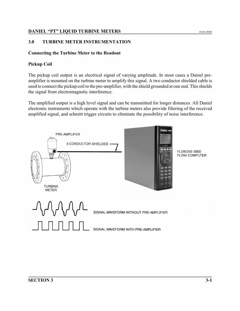
Connecting the Turbine Meter to the Readout
Pickup Coil
The pickup coil output is an electrical signal of varying amplitude. In most cases a Daniel pre-amplifier is mounted on the turbine meter to amplify this signal. A two conductor shielded cable isused to connect the pickup coil to the pre-amplifier, with the shield grounded at one end. This shieldsthe signal from electromagnetic interference.
The amplified output is a high level signal and can be transmitted for longer distances. All Danielelectronic instruments which operate with the turbine meters also provide filtering of the receivedamplified signal, and schmitt trigger circuits to eliminate the possibility of noise interference.

AUG 2009 DANIEL “PT” LIQUID TURBINE METERS
TURBINE METER INSTRUMENTATION3-2
Pre-amplifier
The Universal Preamplifier (Preamp) converts the low level signal from a turbine meter inductivepickup to high level pulses. It is distinguished by the following features:
• Tailored Frequency ResponseThe sensitivity of the Preamp rolls off as frequency increases, matching the characteristic output ofa turbine meter with inductive pickup. High sensitivity at low frequencies allows the turbine meterto operate at its lowest possible flow rates. Reduced sensitivity at high frequencies prevents spuriouscounting due to RFI and transients.
• Common Mode RejectionThe Preamp employs a differential amplifier which responds only to differences between the COIL+and COIL- wires.
• Dual OutputsWith its dual outputs, the Preamp works with virtually any end device. One output swings from 0Vto 5V regardless of the power supply voltage, and is suited for most inputs with thresholds of 4V orless. An open collector output swings from 0V to any available power supply voltage up to 36V,sinking up to 50 mA.
• Wide Power Supply Range, Low Power OperationThe Preamp operates with any power supply voltage from 5.4 to 26V and requires less than 1 mA.It can be added to virtually any system without special power conditioning, and typically with noimpact on power system requirements.
• Bullet-Proof I/OAll field wiring terminals are protected against ESD (electrostatic discharge) and transients.
• Rugged and Convenient PackagingThe Preamp is fully encapsulated in a compact package suitable for mounting on a panel or in astandard 3" ID explosion-proof housing. Pluggable cage-clamp type connectors allow convenient,reliable connections without the need for lugs. Terminals are labeled with signal names to simplifyinstallation.

DANIEL “PT” LIQUID TURBINE METERS AUG 2009
SECTION 3 3-3
UNIVERSAL PREAMPLIFIER
0-5 V OUT CONFIGURATION
_____________________________________________________
UNIVERSAL PREAMPLIFIER
OC OUT CONFIGURATION

AUG 2009 DANIEL “PT” LIQUID TURBINE METERS
TURBINE METER INSTRUMENTATION3-4

DANIEL “PT” LIQUID TURBINE METERS AUG 2009
SECTION 4 4-1
4.0 GENERAL INFORMATION
“PT” Meter Packaging and Shipping
Daniel “PT” Meters are fitted with flange protectors to seal off the inside diameter. All meters arecarefully boxed or crated for protection during delivery. In some cases, meters can be bolted into thetubes on request, but this method is not recommended. There is an extra charge for export crating.
Servicing and Storage
Periodic servicing of the “PT” Meter is desirable to maintain optimum measurement performance.
1. Keep meter clean and free from foreign matter externally and internally.2. Check freedom of motor rotation.3. Rotor should be free to move laterally along the shaft from thrust washer to thrust washer.4. Keep pickup coil and cable connections dry, clean and in good condition.
It is not necessary to disassemble meter for cleaning during normal service conditions unless it issuspected of malfunction or if operational service is discontinued for an extended period of time. Themethod of cleaning depends on the fluid being measured. It is at the discretion of the operator toadopt the most suitable cleaning operation, with consideration given to the materials of which themeter and its parts are made.
Steam must not be used, nor should a higher flow rate than that stipulated for the meter be appliedduring in-line cleaning processes.
To store the meter, stand it on one end flange with both end flanges and pickup coil covered toprotect against foreign matter and temperature extremes. In damp storage areas, damp-proofpackaging with silica gel desiccants is recommended.

AUG 2009 DANIEL “PT” LIQUID TURBINE METERS
GENERAL INFORMATION4-2

DANIEL “PT” LIQUID TURBINE METERS AUG 2009
SECTION 5 5-1
5.0 3" THROUGH 24" PT METER - METER DISASSEMBLY
Disassembly Step 1To remove preamplifier housing, unscrew collar nut on thequick connect union, lift preamplifier housing, unscrew anddisconnect cable connector from pickup coil.
Disassembly Step 2To remove pickup coil, unscrew from coil boss.
NOTE: Preamplifier housing and pickup coil neednot be removed for internal meterdisassembly.

AUG 2009 DANIEL “PT” LIQUID TURBINE METERS
3" THROUGH 24" PT METER DISASSEMBLY5-2
Disassembly Step 3Remove cotter pin from downstream end of shaft.
Disassembly Step 4Remove downstream shaft nut, simultaneously holdingupstream shaft nut to prevent shaft from turning.

DANIEL “PT” LIQUID TURBINE METERS AUG 2009
SECTION 5 5-3
Disassembly Step 5Position meter housing horizontally with one hanger blade in the vertical top position. Slowly push(or tap) downstream end of shaft into downstream hanger hub.
Insert a punch or metal rod into the removal hole of the downstream hanger hub.

AUG 2009 DANIEL “PT” LIQUID TURBINE METERS
3" THROUGH 24" PT METER DISASSEMBLY5-4
Disassembly Step 6Strike upstream end of shaft with a soft headedhammer, loosening downstream hanger assembly.Remove the metal rod from the downstream hangerassembly.
Disassembly Step 7Remove downstream hanger assembly from downstream endof meter housing. Care should be taken not to drop hangerblades.
Disassembly Step 8Remove hanger blades from hanger hub.

DANIEL “PT” LIQUID TURBINE METERS AUG 2009
SECTION 5 5-5
Disassembly Step 9Remove downstream cone from shaft. Thrust washer shouldremain in cone.
Disassembly Step 10Remove rotor from shaft. Leave journal on shaft.
NOTE: 1. “A” is etched on one side of rotor hub,“B” on the other side. Notice which directionrotor was assembled.
2. If bi-directional rimmed rotor meter,remove deflector ring before removing rotor.
Disassembly Step 11Remove journal from shaft. Take care not to drop.

AUG 2009 DANIEL “PT” LIQUID TURBINE METERS
3" THROUGH 24" PT METER DISASSEMBLY5-6
Disassembly Step 12Reach through meter and remove upstream cone from shaft.Thrust washer should remain in core.
NOTE: For most servicing, disassembly is nowcompleted. However, if necessary forthorough cleaning or inspection, completethe following steps:
Disassembly Step 13Remove shaft from upstream end of meter.
Disassembly Step 14Insert shaft (end without nut) into downstream end of meterhousing. Place end of shaft against the downstream hangerhub. With a soft headed hammer strike the shaft looseningthe upstream hanger assembly.
DANIEL “PT” LIQUID TURBINE METERS AUG 2009
SECTION 5 5-7
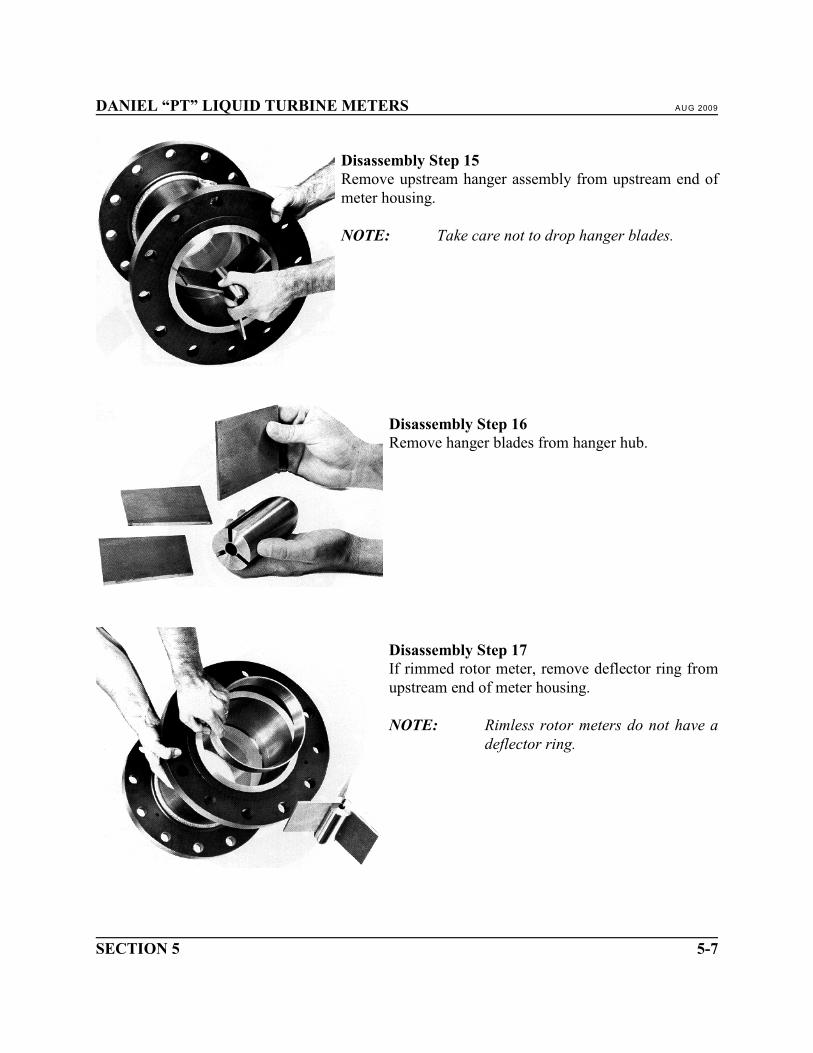
Disassembly Step 15Remove upstream hanger assembly from upstream end ofmeter housing.
NOTE: Take care not to drop hanger blades.
Disassembly Step 16Remove hanger blades from hanger hub.
Disassembly Step 17If rimmed rotor meter, remove deflector ring fromupstream end of meter housing.
NOTE: Rimless rotor meters do not have adeflector ring.

AUG 2009 DANIEL “PT” LIQUID TURBINE METERS
3" THROUGH 24" PT METER DISASSEMBLY5-8
This page intentionally left blank.

DANIEL “PT” LIQUID TURBINE METERS AUG 2009
SECTION 6 6-1
6.0 3" THROUGH 24" PT METER - METER ASSEMBLY
MECHANICAL EQUIPMENT DAMAGE
See Section 7 “INSPECTION” prior to assembly.
Failure to properly clean and inspect all parts according to Section 7 “INSPECTION” mayresult in meter damage and improper operation.
Assembly Step 1If rimmed rotor meter, install deflector ring bysliding it, widest edge first, into upstream end ofmeter housing until contacting the step in the bore.
NOTE: Rimless rotor meters do not have adeflector ring.
Assembly Step 2Insert angled end of hanger blades into the three slotsin a hanger hub. When correctly installed outsidehanger blade edges are parallel to hanger hub. Theupstream and downstream edges are perpendicular tohanger hub.

AUG 2009 DANIEL “PT” LIQUID TURBINE METERS
3" THROUGH 24" PT METER ASSEMBLY6-2
Assembly Step 3Position hanger blades in hanger hub slots to protrudeenough from the flat faced end of the hanger hub to allow theoutside edges of hanger blades to fit inside meter housingbore. Slide assembly, flat faced end first into upstream boreof meter housing. Push hanger blades so downstream edgesare touching deflector ring upstream edge on rimmed rotormeters or touching upstream edge of step in bore on rimlessrotor meters. Push hanger hub forcing hanger blades outwardcontacting meter housing bore. Tap upstream edges ofhanger blades with a soft headed hammer making sure theyare properly positioned. Then strike the upstream end ofhanger hub wedging and locking assembly in place.
Assembly Step 4Insert shaft into center hole of upstream end of upstreamhanger hub.

DANIEL “PT” LIQUID TURBINE METERS AUG 2009
SECTION 6 6-3
Assembly Step 5Put upstream cone, small diameter end first, on downstreamend of shaft, slide into meter, contacting the downstream endof upstream hanger blades.
Assembly Step 6Place journal on shaft over threads. Wipe outside surfacewith a clean cloth.
Assembly Step 7Clean bearing inside surface. Slide rotor on to shaft andjournal, simultaneously sliding journal and rotor along shaftto upstream cone.
NOTE: 1. Install rotor in same direction asdisassembled.
2. If bi-directional rimmed rotor meter installdeflector ring after installing rotor.

AUG 2009 DANIEL “PT” LIQUID TURBINE METERS
3" THROUGH 24" PT METER ASSEMBLY6-4
Assembly Step 8Install downstream cone, largest diameter end first, on toshaft and slide along shaft to rotor.
Assembly Step 9Insert angled edge of hanger blades into the three slots inhanger hub. When correctly installed, outside edges ofhanger blades are parallel to hanger hub and upstream anddownstream edges are perpendicular to hanger hub.
DANIEL “PT” LIQUID TURBINE METERS AUG 2009
SECTION 6 6-5
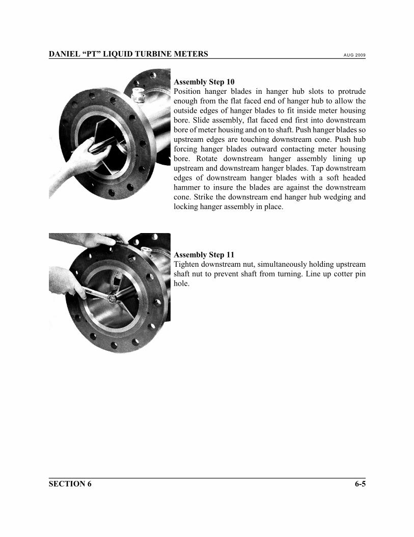
Assembly Step 10Position hanger blades in hanger hub slots to protrudeenough from the flat faced end of hanger hub to allow theoutside edges of hanger blades to fit inside meter housingbore. Slide assembly, flat faced end first into downstreambore of meter housing and on to shaft. Push hanger blades soupstream edges are touching downstream cone. Push hubforcing hanger blades outward contacting meter housingbore. Rotate downstream hanger assembly lining upupstream and downstream hanger blades. Tap downstreamedges of downstream hanger blades with a soft headedhammer to insure the blades are against the downstreamcone. Strike the downstream end hanger hub wedging andlocking hanger assembly in place.
Assembly Step 11Tighten downstream nut, simultaneously holding upstreamshaft nut to prevent shaft from turning. Line up cotter pinhole.

AUG 2009 DANIEL “PT” LIQUID TURBINE METERS
3" THROUGH 24" PT METER ASSEMBLY6-6
Assembly Step 12Insert cotter pin and bend ends around and back to nut.
Assembly Step 13To install pickup coil, clean debris from coil boss and coiltip. Screw in pickup coil.
NOTE: Do not exceed 30 in. pounds of torque.

DANIEL “PT” LIQUID TURBINE METERS AUG 2009
SECTION 6 6-7
Assembly Step 14To install preamplifier housing hold preamplifier housingover pickup coil, connect and hand tighten the cableconnector to pickup coil. Lower explosion proof housingover pickup coil and tighten collar nut of the quick connectunion.
When an XIHL or GUB2 enclosure is fitted, the coupling flame path must be checked andmust not exceed 0.15 mm (0.006").

AUG 2009 DANIEL “PT” LIQUID TURBINE METERS
3" THROUGH 24" PT METER ASSEMBLY6-8
This page intentionally left blank.

DANIEL “PT” LIQUID TURBINE METERS AUG 2009
SECTION 7 7-1
7.0 INSPECTION
Clean and inspect all parts for damage and wear. Replace parts as required. Clean bearings, journalsand thrust washers with solvents and paper towels. Assemble dry. Do not spray lubricants as eithera cleaner or a lubricant.
Upstream and downstream cones should have sharp edges free of nicks. Thrust washers should beseated flat in cone recesses.
Rotor hub and blade edges should be sharp and free of nicks and debris. Rotor blades should not betwisted or bent.
The bearing, which is pressed into the rotor hub, should have an equal amount protruding from bothhub faces. The bearing internal surface and journal external surface should be smooth and free ofscratches, wear spots, chips, and nicks. The bearing and journal are a matched set. For replacement,return the rotor to Daniel Measurement and Control, Inc. It is not recommended that the bearing bereplaced in the field.
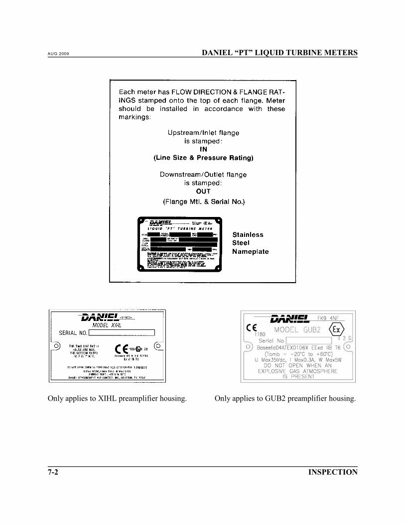
Pt Meter Markings
AUG 2009 DANIEL “PT” LIQUID TURBINE METERS
INSPECTION7-2
Only applies to XIHL preamplifier housing. Only applies to GUB2 preamplifier housing.
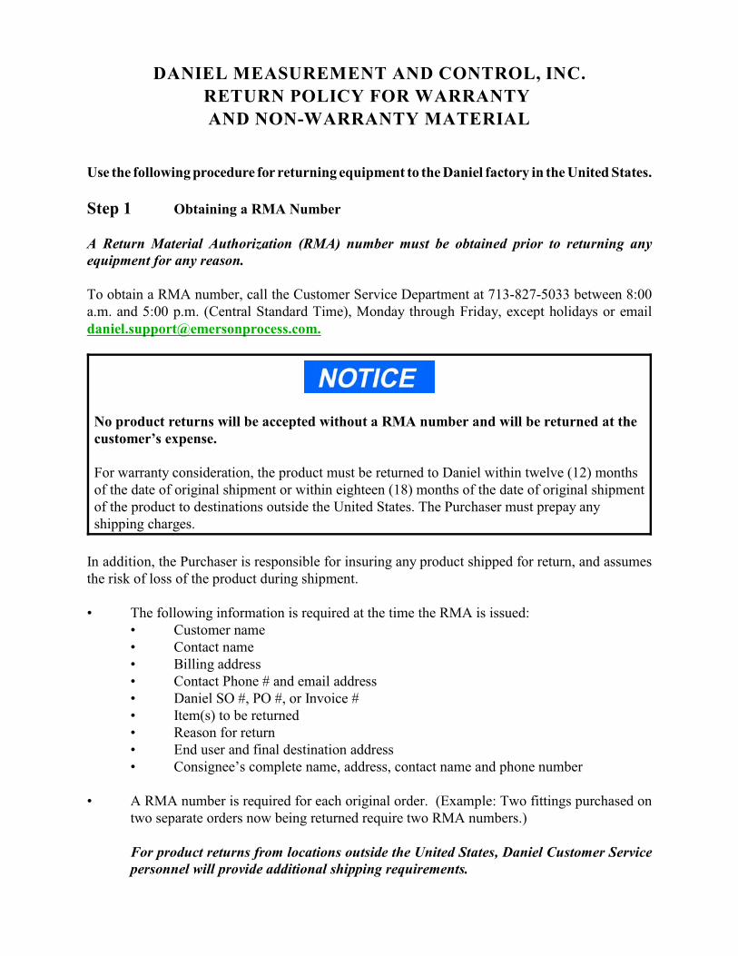
DANIEL MEASUREMENT AND CONTROL, INC.
RETURN POLICY FOR WARRANTY
AND NON-WARRANTY MATERIAL
Use the following procedure for returning equipment to the Daniel factory in the United States.
Step 1 Obtaining a RMA Number
A Return Material Authorization (RMA) number must be obtained prior to returning anyequipment for any reason.
To obtain a RMA number, call the Customer Service Department at 713-827-5033 between 8:00a.m. and 5:00 p.m. (Central Standard Time), Monday through Friday, except holidays or [email protected].
No product returns will be accepted without a RMA number and will be returned at thecustomer’s expense. For warranty consideration, the product must be returned to Daniel within twelve (12) monthsof the date of original shipment or within eighteen (18) months of the date of original shipmentof the product to destinations outside the United States. The Purchaser must prepay anyshipping charges.
In addition, the Purchaser is responsible for insuring any product shipped for return, and assumesthe risk of loss of the product during shipment.
• The following information is required at the time the RMA is issued:• Customer name• Contact name• Billing address• Contact Phone # and email address• Daniel SO #, PO #, or Invoice #• Item(s) to be returned• Reason for return• End user and final destination address• Consignee’s complete name, address, contact name and phone number
• A RMA number is required for each original order. (Example: Two fittings purchased ontwo separate orders now being returned require two RMA numbers.)
For product returns from locations outside the United States, Daniel Customer Servicepersonnel will provide additional shipping requirements.

Step 2 Cleaning and Decontamination
Prior to shipment, thoroughly clean and decontaminate all equipment removing all foreignsubstances. This includes all substances used for cleaning the equipment. The cleaning anddecontamination requirement applies to any part exposed to process fluids or cleaning substances.
Shipping equipment that has not been decontaminated may be in violation of U.S. Department ofTransportation (DOT) regulations. For your reference, the requirements for packaging and labelinghazardous substances are listed in DOT regulations 49 CFR 172, 178, and 179.
If you suspect that a part has been contaminated, the part must be completely drained and flushedto remove contaminants.
MAY CAUSE DEATH OR SERIOUS INJURY TO PERSONNEL
Contents may be under pressure or materials may be hazardous
Follow appropriate handling instructions for accessing pressurized equipment. Avoid contactwith hazardous materials or contaminated units and parts. Failure to do so may result in deathor serious injury.
Decontamination/Cleaning Statement
A blank Decontamination/Cleaning Statement is provided on the “Returned Material AuthorizationRepair Form for Used Equipment”.
• A Decontamination/Cleaning Statement is required for each returned part.• Fully complete each form and include a signature. If the decontamination statement is
incomplete, the customer may be charged for decontamination and cleaning.
If the equipment has been exposed to a known hazardous substance with any characteristic that canbe identified in the Code of Federal Regulations, 40 CFR 261.20 through 261.24, the chemicalabstracts number and hazardous waste number/hazard code must be stated in the space provided onthe form.
Two (2) copies of each Decontamination/Cleaning Statement must be provided:• One (1) copy must be attached to the outside of the package.• One (1) copy must be included inside the package.
Step 3 Material Safety Data Sheets (MSDS)
Provide a Material Safety Data Sheet (MSDS) with the returned equipment for each substance thathas come in contact with the equipment being returned, including substances used fordecontamination and cleaning.
A MSDS sheet is required by law to be available to people exposed to specific hazardoussubstances, with one exception: if the equipment has only been exposed to food-grade substancesor potable water, or other substances for which an MSDS is not applicable, theDecontamination/Cleaning Statement form alone is acceptable.
Two (2) copies of each MSDS must be provided:• One (1) copy must be attached to the outside of the package.• One (1) copy must be provided inside the package.
Step 4 Packaging
Shipping a Device With Possible Contamination
To meet DOT requirements for identifying hazardous substances, ship only one device per package.
Shipping a Device Without Any Potential Contamination
Devices being returned may be shipped together in one package, if there is no potential of foreignsubstance contamination.
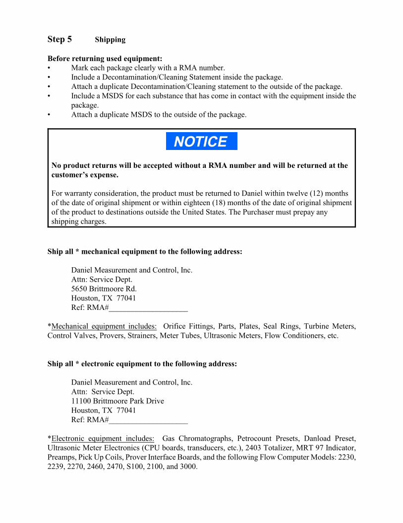
Step 5 Shipping
Before returning used equipment:• Mark each package clearly with a RMA number.• Include a Decontamination/Cleaning Statement inside the package.• Attach a duplicate Decontamination/Cleaning statement to the outside of the package.• Include a MSDS for each substance that has come in contact with the equipment inside the
package.• Attach a duplicate MSDS to the outside of the package.
No product returns will be accepted without a RMA number and will be returned at thecustomer’s expense. For warranty consideration, the product must be returned to Daniel within twelve (12) monthsof the date of original shipment or within eighteen (18) months of the date of original shipmentof the product to destinations outside the United States. The Purchaser must prepay anyshipping charges.
Ship all * mechanical equipment to the following address:
Daniel Measurement and Control, Inc.Attn: Service Dept.5650 Brittmoore Rd.Houston, TX 77041Ref: RMA#____________________
*Mechanical equipment includes: Orifice Fittings, Parts, Plates, Seal Rings, Turbine Meters,Control Valves, Provers, Strainers, Meter Tubes, Ultrasonic Meters, Flow Conditioners, etc.
Ship all * electronic equipment to the following address:
Daniel Measurement and Control, Inc.Attn: Service Dept.11100 Brittmoore Park DriveHouston, TX 77041Ref: RMA#____________________
*Electronic equipment includes: Gas Chromatographs, Petrocount Presets, Danload Preset,Ultrasonic Meter Electronics (CPU boards, transducers, etc.), 2403 Totalizer, MRT 97 Indicator,Preamps, Pick Up Coils, Prover Interface Boards, and the following Flow Computer Models: 2230,2239, 2270, 2460, 2470, S100, 2100, and 3000.

Daniel Measurement and Control, Inc.
Returned Material Authorization
Repair Form for Used EquipmentIncluding Decontamination/Cleaning Statement
1. Return Material Authorization (RMA) Number ____________________________________
2. Equipment to be returned:Model Number _________________________ Serial Number _______________________
3. Reason for return: ____________________________________________________________________________________________________________________________________________________________________________________________________________________________________________________________________________________________
Decontamination/Cleaning Fluids Process
A. List each substance in which the equipment was exposed. Attach additional documents if necessary.
CommonName
CAS# ifavailable
Used for HazardousWaste (20 CFR 261)
EPA Waste Codeif used for hazardous waste
[ ] Yes [ ] No
[ ] Yes [ ] No
[ ] Yes [ ] No
[ ] Yes [ ] No
[ ] Yes [ ] No
[ ] Yes [ ] No
B. Circle any hazards and/or process fluid types that apply:
Infectious Radioactive Explosive Pyrophoric Poison Gas
Cyanides Sulfides Corrosive Oxidizer Flammable Poison
Carcinogen Peroxide Reactive-Air Reactive-Water Reactive-Other(list)
Other hazard category (list):
C. Describe decontamination/cleaning process. Include MSDS description for substances used in decontamination andcleaning processes. Attach additional documents if necessary.
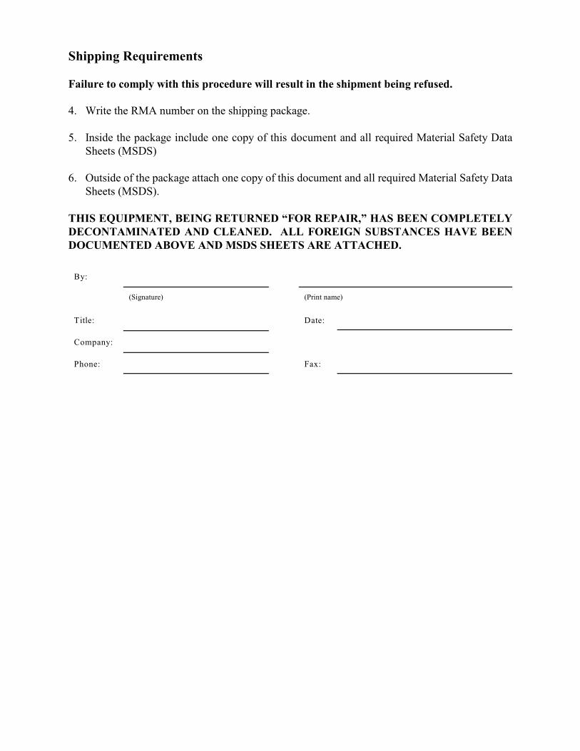
Shipping Requirements
Failure to comply with this procedure will result in the shipment being refused.
4. Write the RMA number on the shipping package.
5. Inside the package include one copy of this document and all required Material Safety DataSheets (MSDS)
6. Outside of the package attach one copy of this document and all required Material Safety DataSheets (MSDS).
THIS EQUIPMENT, BEING RETURNED “FOR REPAIR,” HAS BEEN COMPLETELYDECONTAMINATED AND CLEANED. ALL FOREIGN SUBSTANCES HAVE BEENDOCUMENTED ABOVE AND MSDS SHEETS ARE ATTACHED.
By:
(Signature) (Print name)
Title: Date:
Company:
Phone: Fax:


The sales and service offices of Daniel Measurement and Control are locatedthroughout the United States and in major countries overseas.
Please contact Daniel Measurement Services at11100 Brittmoore Park Drive, Houston, Texas 77041, or phone (713) 827-6314
for the location of the sales or service office nearest you. Daniel Measurement Services offers both on-call and contract
maintenance service designed to provide single-source responsibility for all Daniel products.
Daniel Measurement and Control, Inc., and Daniel Measurement Services, Inc.Divisions of Emerson Process Management reserves the right to make changes to any of its products or services
at any time without prior notification in order to improve that product or service and to supplythe best product or service possible.www.emersonprocess.com/daniel