Embed Size (px)
Citation preview

Damage Detection in a Microencapsulated Dicyclopentadiene
and Grubbs’ Catalyst Self-Healing System
Major Qualifying Project completed in partial fulfillment
of the Bachelors of Science Degree at
Worcester Polytechnic Institute, Worcester, MA
Submitted by:
Zhi Hao (Edward) Li
Carly Morrison
Elise St. Laurent
Professor Amy Peterson, Faculty Advisor
2
Abstract Self-healing polymers are able to repair themselves after being damaged. One type of self-
healing system functions by microencapsulating a healing agent. Microcapsules were prepared to
contain both a healing agent, dicyclopentadiene (DCPD), in addition to a damage detection
agent,1,3,5,7-Cyclooctatriene (COT). These microcapsules were incorporated into an epoxy
matrix to create a damage detecting self-healing polymer. The DCPD-COT microcapsules were
ruptured in the presence of Grubbs’ catalyst, and color change was confirmed. Modified compact
tension specimens were produced that contained DCPD and DCPD-COT microcapsules. Voids
within the polymers as well as inhomogeneous incorporation of catalyst and microcapsules
prevented the specimens from healing, so the effect of COT on the healing efficiency could not be
tested. However, the addition of COT did not significantly impact the polymer’s breaking strength.

3
Acknowledgements
We would like to acknowledge Dr. Amy Peterson, our faculty advisor, Thomas
Partington, machining specialist, Dr. Kathleen Field, and Claire Salvi, Anthony D’Amico, and
Shubhneet Sandhu, our graduate student mentors.

4
Table of Contents Abstract ........................................................................................................................................... 2
Acknowledgements ......................................................................................................................... 3
Table of Figures .............................................................................................................................. 6
1 Introduction .................................................................................................................................. 7
2 Background .................................................................................................................................. 8
2.1 Self-healing polymers ........................................................................................................... 8
2.2 Chemistry of microcapsule-based self-healing polymers ..................................................... 9
2.3 Mechanical Properties ........................................................................................................... 9
3 Literature Review....................................................................................................................... 11
3.1 Self-Healing Process Using Microencapsulated Dicyclopenadiene ................................... 11
3.2 Production of Microencapsulated Dicyclopentadiene Self-Healing Polymers ................... 12
3.3 Accommodating Fluorescent Dyes in Microcapsule-based Self-Healing Polymer Systems
................................................................................................................................................... 13
3.4 Fluorescence in Alternative Healing Systems .................................................................... 15
3.5 Mechanical Testing for Healing Efficiency ........................................................................ 16
4 Methodology .............................................................................................................................. 18
4.1 Microencapsulation Process................................................................................................ 18
4.2 Grubbs’ Catalyst Protection ................................................................................................ 18
4.3 Differential Scanning Calorimetry ...................................................................................... 18
4.4 Thermogravimetric Analysis .............................................................................................. 19
4.5 Testing Color Change ......................................................................................................... 19
4.6 Production of Epoxy Bars ................................................................................................... 19
4.7 Production of Modified Compact Tension Specimens ....................................................... 20
4.8 Mechanical Testing ............................................................................................................. 21
5 Results and Discussion .............................................................................................................. 22
5.1 Microencapsulation ............................................................................................................. 22
5.1.1 Scanning Electron Microscopy (SEM) Analysis ......................................................... 22
5.1.2 Thermogravimetric Analysis ....................................................................................... 24
5.2 Color Change Test .............................................................................................................. 27
5.3 Production of Mechanical Testing Specimens .................................................................... 29
5
5.3.1 Differential Scanning Calorimetry Results .................................................................. 29
5.3.2 Microscope and SEM Images of the Specimens .......................................................... 35
5.3.3 Observations Made During Machining of the Specimens ........................................... 38
5.4 Mechanical Testing ............................................................................................................. 39
6.0 Conclusions and Recommendations ....................................................................................... 42
6.1 Conclusions ......................................................................................................................... 42
6.2 Recommendations ............................................................................................................... 42
Appendix ....................................................................................................................................... 44
Appendix A: Microencapsulation Procedure10 ......................................................................... 44
Appendix B: Grubbs’ Protection Procedure21........................................................................... 44
References ..................................................................................................................................... 45

6
Table of Figures Figure 2.1: Modified Compact Tension Specimen………………………………………… 9
Figure 3.1: Microcapsule Based Self-Healing……………………………………………... 11
Figure 3.2: Tapered Double-Cantilever Beam Specimen………………………..………… 16
Figure 4.1: Specimen Dimensions…………………………………………………………. 20
Figure 4.2: System for Loading Specimen……………………………………………….… 21
Figure 4.3: ElectroPuls with Specimen Holders…………………………………………… 21
Figure 5.1: DCPD Microcapsule SEM Image……………………………………………… 22
Figure 5.2: DCPD and COT Microcapsule SEM Image…………………………………… 23
Figure 5.3: Size Distribution of 198 DCPD Microcapsules………………………………... 23
Figure 5.4: Size Distribution of 310 DCPD-COT Microcapsules…………………………. 24
Figure 5.5: TGA of DCPD Microcapsules…………………………………………………. 25
Figure 5.6: TGA of DCPD-COT Microcapsules…………………………………………… 26
Figure 5.7: TGA for Cure Cycle 1………………………………………………………….. 27
Figure 5.8: TGA for Cure Cycle 2………………………………………………………….. 27
Figure 5.9: Time-Lapse of DCPD-COT Microcapsule Color Test………………………… 28
Figure 5.10: Uncured Epoxy DSC Test Results……………………………………………. 29
Figure 5.11: Determination of Enthalpy of Curing Reaction for Uncured Epoxy…….…… 30
Figure 5.12: Determination of Tg for Uncured Epoxy………………………………...…… 31
Figure 5.13: Cured Epoxy DSC Test Results………………………………………………. 32
Figure 5.14: Determination of Enthalpy of the Curing Reaction for Cured Epoxy…...…… 33
Figure 5.15: Determination of Tg for Cured Epoxy…………………………………..……. 34
Figure 5.16: SEM Image of Cab-o-sil Surface ……………….……………………………. 36
Figure 5.17: SEM Image of Cab-o-sil Surface………………..……………………………. 36
Figure 5.18: Zeiss Image of Cab-o-sil Surface………………..……………………………. 37
Figure 5.19: Voids and Microcapsules near DCPD Sample Crack Surface……………..…. 37
Figure 5.20: SEM Image of DCPD Crack Edge……………………………………………. 38
Figure 5.21: Specimens D5 and C6 Before Testing……………………………………..…. 39
Figure 5.22: Loading of DCPD-COT Specimen…………………………………………… 40
Figure 5.23: Breaking Force of Modified Compact Tension Specimens………………..…. 41
7
1 Introduction
Self-healing polymers are able to repair themselves after damage to recover some or all of
their original material properties. This ability enables prolonged use of the material after damage
events, which is not possible in other polymers. Self-healing polymers are also able to heal
autonomously, enabling the continued use of polymers after damage without the need for operators
to take any action to repair the polymer.1 Although self-healing capabilities can extend the lifetime
of a polymer, these capabilities are limited by the method of self-healing that is used.
Microcapsule-based self-healing polymers, for example, contain microencapsulated healing agents
and are only capable of repairing a single damage event. Once the healing agent has reacted, it
cannot heal damage at that site again, which means further damage will not be repaired. It is often
hard to detect damage in polymers prior to a catastrophic event because of rapid crack propagation.
As a result, the damage that self-healing systems are designed to heal is on the micro scale and it
is often barely visible. This problem can be overcome by adding a means of detection to the self-
healing polymer to visually distinguish a damaged site from the bulk polymer.2 The application of
self-healing systems will ultimately be in composite materials such as airplane wings or wind
turbine. However, for research purposes it is easier to work with polymers without the composite
additives.
Adding a detection agent to the healing agent is one method of allowing a healing site to
become more visible. One possible detection agent is 1,3,5,7-Cyclooctatetraene (COT). COT
polymerizes in the presence of Grubbs’ catalyst, causing a color change but it is incapable of being
used as the healing agent. If COT can be encapsulated with a healing agent, this can allow for a
system with both healing and detection.3,4 However, the addition of COT in microcapsule-based
self-healing polymers also introduces complications since detection agents have the potential to
affect material properties of the polymer. Detection agents may also interfere with the healing
chemistry that takes place during damage. Therefore, research on the interaction between detection
agents, bulk polymers, and encapsulated healing agents is valuable in determining how functional
self-healing polymers with damage detection can be.5
The research questions this project will answer are:
Does COT provide a means of detecting damage in a microencapsulated dicyclopentadiene
(DCPD) and Grubbs’ catalyst self-healing system?
Does the use of COT as a detection agent affect the material properties of the
microencapsulated DCPD and Grubbs’ catalyst self-healing system?
We also attempted to determine whether the use of COT as a detection agent affects the fracture
toughness healing efficiency of the microencapsulated DCPD and Grubbs’ catalyst self-healing
system.

8
2 Background
2.1 Self-healing polymers
Materials science focuses on improving performance of materials by widening materials’
range of applications, quantifying material properties, and identifying failure mechanisms.
Traditionally, materials have been engineered to prevent failure, but more recently, self-healing
materials have taken a different approach. Instead of designing to prevent failure for as long as
possible, the focus in self-healing materials is to facilitate recovery of the material’s original
properties. Using this self-healing approach by itself or in addition to traditional approaches is a
promising area of materials engineering which opens up possibilities for improved materials.2
The three prevailing methods of self-healing materials are capsule-based, vascular, and
intrinsic. These categories are defined by how healing agents are separated from the bulk matrix
and have tradeoffs between number of healing cycles, bulk functionality after healing, and volume
that can be healed.5
Capsule-based self-healing materials are materials whose healing agents are contained in
capsules distributed in a bulk matrix. The capsules rupture to release healing agents when the bulk
matrix is damaged. Consequently, the material loses its ability to heal when capsules are depleted
due to a previous damage event. A few variations on capsule-based self-healing exist, but the more
prevalent ones include capsule-catalyst and multi-capsule varieties. In capsule-catalyst, a catalyst
is dispersed along with the healing agent capsules to facilitate the healing.6 However, multi-
capsules use multiple reactants that can be separately encapsulated, which are activated when
mixed in the matrix during healing. Other less commonly used capsule-based self-healing
variations include latent functionality in the bulk matrix and phase separation. Latent functionality
is similar to capsule-catalyst, with the exception that the catalyst is unnecessary due to properties
of the bulk. Phase separation refers to a variation that uses a minority phase in the bulk to separate
healing agents.6
Vascular-based self-healing materials employ channels or capillaries to keep healing
agents separate from the bulk. With connected gridding of healing agents, multiple healing events
can occur at the same location until pathways become too blocked or healing agent is depleted.7
Hollow glass fibers are commonly used because they are relatively unreactive and glass processing
techniques already exist for other applications. Multiple isolated networks of vascular systems can
be used to support two part healing chemistries or catalysts.7 Structural health monitoring systems
can also be incorporated within a vascular network by embedding carbon fiber laminates into a
bulk polymer so that changes in resistance sensed by the laminate triggers an inherent local heating
event. With a thermosetting epoxy, the heat promotes self-healing by initiating the epoxy
chemistry and the epoxy is chosen to have a close solubility parameter to prevent phase separation.8
Intrinsic self-healing materials do not separate healing agents from a bulk because the self-
healing mechanism depends on the intrinsic properties of these materials. They contain inherent
reversibility of bonding, therefore only a limited number of materials can be used for intrinsic self-
healing. Additionally, since most material properties are dependent on conditions the material is
subjected to, such as temperature and pH, intrinsic self-healing materials have a limited range of

9
practicality compared to other self-healing options. Consequently, intrinsic self-healing is not as
flexible when designing for a particular application. Polymers containing matrices with hydrogen
bonding, thermoreversible bonding, or a dispersed thermoplastic phase are suited to intrinsic self-
healing.9
2.2 Chemistry of microcapsule-based self-healing polymers This project is focused on microcapsule-based self-healing polymers. The successful
deployment of microcapsule-based self-healing polymers ultimately relies on two chemical
processes: microcapsule formation and the reaction of the healing agent. Poly(urea-formaldehyde)
will be used to encapsulate the healing agent dicyclopentadiene.
Poly(urea-formaldehyde) capsules are prepared in an oil and water emulsion under
agitation.10 During microencapsulation, urea and formaldehyde undergo a polymerization reaction
at the oil-water boundary layer to form poly(urea-formaldehyde) and encapsulate the healing
agent.11 The polymerization reaction occurs in two steps: addition and condensation. During the
addition reaction, urea reacts with formaldehyde to form monomethylol urea. Next, mono methylol
urea condenses to form the polymer chain. This process then repeats to form the poly(urea-
formaldehyde) polymer. See appendix for reaction diagrams.11
Dicyclopentadiene (DCPD) is a commonly used healing agent in self-healing polymers due
to its ability to polymerize quickly with minimal shrinkage during healing, long shelf life, low
viscosity, and low volatility.12 DCPD polymerizes via ring opening metathesis polymerization
(ROMP), which requires the use of a Grubbs’ catalyst.5 During ROMP, the double bond within
the 6 carbon ring (Reaction 2.3) is broken and reformed with another broken double bond from a
second DCPD monomer.13 This process repeats, adding DCPD to the poly dicyclopentadiene
chain. The newly formed poly(dicyclopentadiene) then fills damage sites and heals damage in the
bulk polymer.
2.3 Mechanical Properties Polymers and polymer composites are used for a variety of applications. They have been
increasingly used in aircraft, cars, ships, and construction industries due to the high strength to
weight ratios and tailorability of properties that they offer. However, polymers are also brittle and
these applications require better material properties such as resistance to fracture, so that the
polymers can be used to replace traditional materials. Self-healing polymers can help to improve
durability as well as other material properties without the need for the damage to be detected. A
common issue with polymer materials is microcracking, internal small cracks that can reduce the
material’s integrity. Crack propagation is also how material properties are weakened after impact
and cyclic fatigue damage. Therefore, a common method of mechanical testing, especially for
microcapsules systems, is fracture toughness.1
Fracture toughness is a measure of a material’s resistance to fracture when it contains a
crack. One method used in testing the fracture toughness a self-healing polymer is the modified
compact tension test.14 In this test, a specimen with the geometry shown in Figure 2.1 is subjected
to a tensile loading stress. The specimen is notched and contains an arresting hole. Prior to testing,

10
a pre-crack is made in the notch of the specimen. The specimen is then loaded using dowels in the
two holes shown in Figure 2.1. As the tensile load is increased, a crack is expected to form in the
specimen propagating from the pre-crack and stopping at the arresting hole. The load at which this
occurs can then be used to determine the fracture toughness of the polymer sample. The modified
compact tension test is useful in measuring the properties of self-healing polymers because the
geometry of the specimen produces a crack of consistent length, enabling the determination of the
fracture toughness of the sample. Further, the geometry of the modified compact tension specimen
is well suited for testing the healing properties of the polymer because the crack is not enabled to
propagate through the entire polymer and the sample consequently remains in one piece after
testing. This means that the crack surface is fixed in its alignment and is able to heal without the
need for the surface to be aligned by human intervention.14
Figure 2.1: Modified Compact Tension Specimen14
Self-healing capabilities are needed to improve polymers as polymers become more widely
used as a material. However, self-healing polymers are especially important because they can
repair damage without the need for human intervention. If damage cannot be visually inspected or
heard through a tap-test, then it is often costly to detect. In-depth inspection techniques include
examination with ultrasonic devices, thermography, laser shearography, and laser interferometry.
These methods all need technical equipment to detect damage, which is impractical in some
situations and possible repair options can be costly.15 A system that combines damage detection
and self-healing properties would allow a material to keep its structural integrity until human
intervention is able to take action.

11
3 Literature Review
3.1 Self-Healing Process Using Microencapsulated Dicyclopenadiene
Dicyclopentadiene (DCPD) can be encapsulated and used as a healing agent. In order to
polymerize DCPD, however, a Grubbs’ catalyst must also be incorporated into the self-healing
polymer as an additive. Grubbs’ catalysts are metal carbene complexes.16 In a metal carbene
complex, the carbene complexes with a transition metal that can accept the carbene’s lone pair
using vacant d-orbitals.17 In the Grubbs’ catalyst, a ruthenium compound complexes with the
carbene. The second and third generation Grubbs’ catalysts are used for ring opening metathesis
polymerization (ROMP).18
The Grubbs’ catalyst serves to metathesize the functional groups of olefins across their
double bonds, as shown in Reaction 3.1.16
Reaction 3.1 – ROMP Process
During olefin metathesis, the double bond of two olefins are severed. One severed double bond
half of the first olefin then reacts with one of the severed double bond halves of the second olefin
to form a new compound. The products of olefin metathesis can be any stereochemical
combination of pairings between the double bond halves. ROMP is a specific type of olefin
metathesis in which the double bond is within the ring of an aromatic compound. When the double
bond of the ring is broken, the ring opens. Each severed double bond half is then reformed into a
double bond with the severed double bond half of another opened ring, joining the carbon chains
of the former rings together. This process repeats, creating the carbon chain that makes up the new
polymer, poly(DCPD). The ROMP process for DCPD is shown in the appendix.
When a microencapsulated DCPD-based self-healing polymer is damaged and the
microcapsules at the damage site rupture, DCPD is released from the microcapsules and undergoes
ROMP using the Grubbs’ catalyst embedded within the polymer.12 The newly formed poly(DCPD)
then serves to repair the damaged area by replacing the damaged bulk polymer. This process is
illustrated in Figure 3.1

12
Figure 3.1: Microcapsule-based Self-Healing
3.2 Production of Microencapsulated Dicyclopentadiene Self-Healing Polymers To form the microcapsules, it is essential that an oil and water emulsion is created. This
allows the poly(urea-formaldehyde) (PUF) to encapsulates the oil phase, where the healing agent
resides.10 A mixture of ethylene-maleic anhydride copolymer (the oil phase) and deionized water
are mixed under agitation then urea, ammonium chloride, and resorcinol are added to the solution,
and the pH of the solution is adjusted to 3.5. 10 DCPD is then added to the solution and the solution
is re-emulsified under agitation. 10,19 The agitation rate can be used to control the size of these
droplets, which determine the size of the microcapsules.10 Formaldehyde is added to the mixture
and polymerizes to form PUF at the oil-water boundary layer.20 After the reaction has run to
completion, which can take several hours, the solution is cooled.10,19 The microcapsules can then
be separated from the solution through filtration, rinsed with deionized water, and air dried. 10
Grubbs’ catalyst is very sensitive to air and it needs to be protected before adding it to an epoxy
system. This can be done by encapsulating it in paraffin wax though a similar an emulsion
procedure to the microencapsulation.21
The microcapsules and Grubbs’ catalyst are added to the polymer. The polymer is a cured
epoxy resin, which is a thermosetting polymer. An epoxy is a compound containing a three
membered ring with an oxygen atom outside the main carbon chain.22 When an epoxy reacts with
a curing agent, such as an amine, the three membered ring is broken and the curing agent and
epoxy react to form a highly cross-linked thermosetting polymer. This high degree of cross-linking
produces a thermosetting polymer with high toughness and mechanical strength, desirable thermal
and electrical qualities, and high corrosion resistance.22
Commercial thermosetting polymers typically contain several additives intended to
improve their properties. For example, anti-oxidizing agents can be added to thermosets to improve
their resistance to oxidative degradation, fillers can be added to improve the cost or mechanical
properties of thermosets, and surfactants can be added to improve the dispersion of other additives
within the thermoset.23 Since additives are widely used in thermosetting polymers, their effects
and the procedure for adding them are generally well understood. In epoxy resin thermosets, these
additives are added to the epoxy before curing takes place. 19 In DCPD based self-healing
polymers, the microcapsules and Grubbs’ catalyst are dispersed in the epoxy before curing takes

13
place. Homogenous dispersion is achieved with a planetary mixer. The epoxy mixture is poured
into a mold and then cured in an oven.
Self-healing polymers can also be used in composite applications.5 Glass fiber or carbon
fiber reinforced self-healing polymer composites exhibit improved mechanical properties and
could be used in a wider range of applications than self-healing polymers. However, when using
standard ceramic composite material, only the thermosetting polymer phase would possess self-
healing characteristics. Any damage that affected the ceramic composite material would be
irreparable and material properties of the self-healing polymer composite would only be partially
recoverable. Self-healing polymer composites can be produced through open molding by
dispersing the microcapsules and Grubbs’ catalyst within the epoxy, dispersing the ceramic
composite material in the epoxy, and then curing the epoxy in a mold of the desired shape.
However, in the case of self-healing polymers special care must be taken to avoid rupturing the
microcapsules when dispersing the ceramic composite material in the epoxy.
3.3 Accommodating Fluorescent Dyes in Microcapsule-based Self-Healing Polymer Systems Microcapsule-based self-healing is dependent on capsules used to release healing agents.
Therefore, a given location within a bulk matrix is unable to heal repeatedly since capsules will be
depleted by the first healing. Healing extends the life time of the polymer but after a healing event,
the lifetime of the polymer in that area is limited as if it were an unmodified polymer. Fluorescent
dyes encapsulated along with healing agents can been used to address this concern since depleted
areas are highlighted by released dye. Self-healing materials which incorporate encapsulated dye
can be visually inspected, providing a higher level of reliability when deciding whether or not to
replace the part in service.
DCPD healing agent chemistries and PUF encapsulation described in Sections 3.1 and 3.2
are prevailing methods of self-healing in the literature, making fluorescent dyes compatible with
these systems convenient. DCPD and other ROMP compatible compounds have been successfully
encapsulated alongside fluorescent dye derivatives of 4,4’-diamino-2,2’-stilbenedisulfonic acid. 24
Noh and Lee25 have shown by scanning electron and fluorescent microscope observations that this
method of combining self-healing chemistries with fluorescent indicators is possible. However,
there is a fundamental lack of understand of how fluorescent dyes affect degree of polymerization
in ROMP based healing agent chemistries, healing efficiencies, and properties of material after
healing.
Early methods of introducing visibility to damage sites in microcapsule-based self-healing
polymers included addition of dyes to previously researched microcapsule. However, many of
these early attempts ran into issues of compatibility with fluorescent dye and microcapsule
material. Microcapsule synthesis is sensitive to any small changes in the core material such as
adding a dye, manufacturing procedures involved with order of operation, ratio of reagents, and
conditions of reaction.26 As a result, papers describing the success of adding dye based damage
indicators are mostly concerned with explaining their experimental studies to determine
microcapsule recipes that adequately hold the core material. Literature has focused more on

14
ensuring that damaged sites fluoresce, with less concern given to how much the damaged sites
fluoresce. More focus is put into improving the microcapsule that surrounds the healing agent and
dye combination. Furthermore, there are secondary concerns noted by Li and associates27 of
restrictions due to weak adhesion of microcapsules to the bulk matrix, which reduces the original
fracture toughness and tensile strength of the self-healing polymer. The introduction of dye based
damage detection and all of its advantages in this study came at the cost of reduced original
material properties.
More favorable fluorescent dyes would incorporate visual detection methods while also
facilitating the healing process. Ideal detection mechanisms would also express immediate color
change that transitions over time to show the act of healing. One system that has the potential to
meet both of these goals incorporates the healing agent 1,3,5,7-Cyclooctatetraene (COT) with a
Grubbs-Love catalyst. These additives have potential compatibility with DCPD, which could
improve the healing process, while allowing detection.3,4
Finding a suitable recipe for capsules that would contain the COT healing agent and
Grubbs-Love catalyst presented as much of a challenge for Odom et al. as choosing the healing
agent and catalyst.3,4 NMR spectroscopy was performed before and after breaking capsules with a
mortar and pestle to determine if COT degraded inside capsules. Thermogravimetric analysis
(TGA) was performed to determine thermal stability of microcapsules to ensure shell walls would
survive. These results showed that capsules lose some small quantity of material even below the
degradation temperature of capsules. Extensive experiments were performed on different
encapsulation recipes to avoid premature color change from ruptured capsules. A final
microcapsule recipe using COT as a core material was described as containing double the amount
of urea and formaldehyde to produce microcapsules with much thicker shell walls.3,4
Pyrene has potential to be a damage indicator in microcapsule-based self-healing polymers
that use a healing agent, such as DCPD, that reacts with a catalyst to undergo ROMP. Pyrene and
its derivatives are already commercially used to manufacture dyes that function as molecular
probes under fluorescence spectroscopy.28 Turro and Arora29 have used pyrene to observe
interactions of water-soluble polymers in dilute solutions to take advantage of sensitivity of pyrene
to the polarity of neighboring compounds that make up its environment. DCPD and poly(DCPD)
both have low solubility in water so it is likely that pyrene will not fluoresce as brightly as it does
in other pyrene applications.30 However, pyrene is still a candidate as a damage indicator because
even a small amount of fluorescence would provide enhanced damage visibility. Another possible
way to incorporate pyrene as a damage indicator is to attach pyrene groups onto norbornene, since
norbornene can participate in ROMP. These pyrene derivatives have been used successfully in
biological fluorescence detection applications and norbornene healing agent chemistries have been
previously studied.31
Pyrene must be encapsulated before it is useful in microcapsule-based self-healing
polymers. Pyrene should be able to be encapsulated in the same way that DCPD is encapsulated
described in Section 3.2 because pyrene is five orders of magnitude more soluble in oil than it is

15
in water.32 A variation of the recipes used for DCPD may need to be used because microcapsules
can be very sensitive to the materials which they are encapsulating.
Fluorescent dyes have been used within the field of self-healing polymer microcapsules
outside of assessing serviceability of a bulk polymer after damage. Alternatively, fluorescent dyes
can be used to gauge the integrity of the microcapsules. McIllroy et al. used Rhodamine B
successfully as a fluorescent dye to gauge performance of amine filled microcapsules. This
fluorescent dye was used to gauge the microcapsules integrity because encapsulation is usually
dependent on emulsions between water and oil phases but amines are reactive in water, therefore
this encapsulation has been difficult to achieve.33 Perylene flourescent dye was also used by the
same research group to observe core material of binary microcapsules with liquid phases separated
by Pickering stabilizers.31 Although the primary purpose of Rhodamine B and perylene fluorescent
dye was to assess microcapsule integrity, both also have potential to be used as fluorescent dyes
for detection of damage sites.
3.4 Fluorescence in Alternative Healing Systems Damage visibility is important for self-healing systems other than those based on
microcapsules. Pang and Bond2 incorporated visual indicators into their vascular self-healing
system. Specifically, they were interested in introducing a UV fluorescent dye into a hollow fiber
polymer composite matrix. The fluorescent dye used was Ardrox 985, and it was an effective
damage detection agent. The point of the study was to detect low velocity impact damage, which
can weaken structural integrity but is hard to detect. From their research, it is clear that the UV
fluorescent dye worked effectively for damage detection under a UV light. However, the UV
fluorescent dye did not indicate whether the site has been fully healed. These findings were also
substantiated by ultrasonic C-scans, which are able to detect fractures in polymers. The hollow
fiber system had healing efficiencies of 93%, but the effectiveness of the healing decreased with
longer storage because acetone in the system caused the epoxy to degrade over time.
Other dyes have also been used in self-healing hollow fiber polymer matrices. One
interesting additive that worked well was an X-ray opaque dye, di-iodomethane. Bleay et al.34
combined the dye with the healing agent and filled the hollow fiber tubes using capillary action
and a vacuum. The hollow fiber tubes were embedded in a polymer matrix and X-radiographs were
taken that confirmed that dye was distributed in the tubes. Impact damage was inflicted on the
polymer composite and new images were taken. These X-radiograph images clearly showed a
concentration of the X-ray dye at the impact damage site. Klinga and Czigánya35 used Rhodamine
B, another dye that has been effective when added to a self-healing agent. They found that using a
UV lamp was the most effective way to quickly visualize the damage. Since they used hollow
fibers, it was necessary to color the outside of the polymer matrix so that the undamaged section
would not fluoresce as well.
There are a wide variety of systems that exhibit mechanochromic behavior, which is the
ability to react visibly to damage from a mechanical force.36, 37, 38 Most of these systems have not
been tested with self-healing agents, but they show that other mechanisms are available for damage
detection. An area of interest includes adding proteins with fluorescent characteristics into

16
polymers. One article describes combining chaperones from an organism with other proteins into
a complex that exhibits fluorescence resonance energy transfer (FRET) when subjected to
structural deformation. The mechanical stress causes the complex to separate and emit
fluorescence.36 Another article incorporates an enhanced yellow fluorescent protein (eYFP) at the
glass fiber and polymer interface in a composite material.37 An additional method for damage
detection is a shift in color. Lowe and Weder38 add excimers into a polymer blend. When the
excimers are aggregated, which can be induced, they produce a red shift under UV light. After
deformation, the excimers are dispersed producing a blue color under UV light. These articles
represent just a small collection of the possible ways to improve damage detection using
mechanochromic systems. Research on mechanochromic behavior is a thriving area because of the
importance of damage detection in polymers and polymer composites.
3.5 Mechanical Testing for Healing Efficiency Adding a detection agent to a self-healing system can affect the polymer’s healing
efficiency. Healing efficiency is a ratio of the mechanical properties of a polymer where healing
has occurred to that of the original polymer. There are a variety of methods for examining the
mechanical properties of self-healing polymers. These test methods include fracture toughness,
compression, and a three or four point bend test.
For microcapsule-based self-healing polymers, fracture toughness has been the property
that is most frequently tested. Often fracture toughness is tested using a tapered double-cantilever
beam specimen. Fracture toughness is a measure of a material’s resistance to fracture when it
contains a crack. The test involves making a pre-crack then applying a load until the specimen
breaks. Since only the load has to be determined and no crack lengths have to be measured, it is a
relative easy test to run.39 However, the tapered double-cantilever beam specimen is a very specific
shape, as seen in Figure 3.2, and is hard to mold.
Figure 3.2: Tapered Double-Cantilever Beam Specimen19
The modified compact tension test can also be used to measure fracture toughness and
determine healing efficiency.14 The geometry used for the specimen in this test is shown in Figure
2.1 in Section 2.3. The specimen undergoes tensile loading until a crack forms in the specimen and

17
propagates from the pre-crack located in the notch of the specimen to the arresting hole. The
specimen is then left to heal under high or low pressure conditions and retested in the same way.
Like the tapered double-cantilever beam test, the healing efficiency of the modified compact
tension specimen can be determined using the peak load of the specimen before and after healing,
making this method of testing a simple way of determining healing efficiency. This method also
has the advantage of using a specimen geometry that remains in one piece after fracture, and can
heal without the need for human intervention to realign the crack surface, reducing the possibility
for error. 14

18
4 Methodology In order to meet the objectives of this project, a set of microcapsules containing the healing
agent dicyclopentadiene (DCPD) and another set of microcapsules containing both DCPD and
1,3,5,7-cyclooctatetraene (COT) were prepared. The DCPD-COT microcapsules were tested by
damaging them and then monitored them for color change. After it was confirmed that the samples
could undergone color change, the microcapsules were incorporated into epoxy test specimens
along with the Grubbs’ catalyst. The specimens were tested in order to determine the effect that
the healing and detection agents had on the mechanical properties of the polymer.
4.1 Microencapsulation Process Microcapsules were prepared in solution following the procedure adapted from Brown et
al. which is available in Appendix A.10 During the microencapsulation process, a stir rate of 550
rpm was used. One set of microcapsules contained DCPD and another set of microcapsules
contained DCPD and COT. For the DCPD-COT microcapsules, the procedure from Brown et al.
was modified by replacing the 30 mL of DCPD with 20 mL of DCPD and 10 mL of COT. This
formulation was developed taking into account the procedures of Odom et al. for COT3,4
encapsulation and White et al. using a smaller proportion of DCPD in their self-healing system.12
The microcapsules were separated from the solution using vacuum filtration. They were allowed
to dry on the filter paper for 24 hours in a fume hood before storing them in glass vials. The
microcapsules were stored in the vials up to three weeks prior to using them in the production of
the self-healing epoxy bars.
4.2 Grubbs’ Catalyst Protection
Second generation Grubbs’ catalyst was used as the catalyst for the polymerization of
DCPD and COT. The Grubbs’ catalyst was protected by coating it in wax. The purpose of coating
the Grubbs’ catalyst was to ensure that the catalyst was not deactivated by either exposure to air
or by the amine used to cure the epoxy during the production of the epoxy bars.21 Prior to coating,
0.5 g Grubbs’ catalyst was enclosed in a vial with 9.6 g of paraffin wax in a glove box. The vials
were left in the glove box under refrigerated conditions until the coating procedure. Two vials, or
1 gram of catalyst, were prepared in this way. The Grubb’s catalyst was encapsulated according to
the procedure used by Rule et al., which is available in Appendix B.21 The resultant wax-coated
particles were separated from the solution using vacuum filtration. The wax-coated Grubbs’
catalyst was dried on filter paper in a room temperature vacuum oven for three hours before storing
it in vials. The protected catalyst was stored in the vials up to two weeks prior to using them in the
production of the self-healing epoxy bars.
4.3 Differential Scanning Calorimetry
Differential scanning calorimetry (DSC) was performed on uncured epoxy and cured
epoxy, so that information about the percent cure of the specimen bars could be determined. The
uncured sample was taken before pouring uncured epoxy into the bar mold. The cured sample was

19
prepared by grinding down a chip of the epoxy bar with a mortar and pestle to yield a solid sample.
Samples were loaded into pans before the sample pans were cold welded to a lid. Masses of pans,
lids, and samples were each recorded as required input for the instrument. A 52.4 mg reference
pan made up of a lid and a Concavus Pan Al cold welded together was used on both DSC runs.
Both samples were subjected to a ramp from room temperature up to 250 ºC, ramped down to -50
ºC, and then ramped up to 250 °C all at 10 °C/min. The DSC was performed on a Netzsch 214
Polyma instrument.
4.4 Thermogravimetric Analysis
Microcapsules were subjected to Thermogravimetric Analysis (TGA) using a Netzch 209
F1 Libra. TGA was used to evaluate the success of microencapsulation and to examine the effects
of the epoxy bar curing process on the microcapsules. Conclusions drawn from the TGA
experiments were used to evaluate success of microencapsulation and were supplemented by
Scanning Electron Microscopy (SEM) of microcapsule samples.
TGA was used to evaluate the success of the microencapsulation. Microcapsules were
loaded into the crucible and subjected to heating from 30 ºC to a plateau of 130 ºC for 45 minutes
before being heated again to 600 ºC at heating rates of 10 °C/min. A mortar and pestle were used
to prepare crushed capsules which were subjected to the same time and temperature profile for
comparison.
Additionally, TGA was used to measure survival of microcapsules during epoxy bar curing
process by applying the same conditions that were used in curing. Microcapsules were heated at
heating rates of 10 °C/min from 30 ºC to a plateau of 120 ºC for two hours and then ramped up to
a 140 ºC plateau for another two hours. After observing a significant mass loss in the initial TGA
used to examine effects of epoxy bar curing process on microcapsules, another TGA was
performed with lower plateau temperatures. A subsequent TGA set to examine survival of
microcapsules during epoxy bar curing process subjected of microcapsules loaded into the crucible
to a ramp from 30 ºC to a plateau of 100 ºC for two hours before another ramp to a plateau of 120
ºC for two more hours.
4.5 Testing Color Change
A color change test was performed before making the epoxy bars. In this test, 87.5
milligrams of microcapsules and 9.4 milligrams of wax protected Grubb’s catalyst were placed in
the center of a microscope slide. Another microscope slide was placed on top, and the two slides
were pushed together to ensure the rupture of microcapsules. Pictures were taken of the slide at
zero hours, one hour, and seventeen hours.
4.6 Production of Epoxy Bars Two epoxy bars were prepared for mechanical testing, one with DCPD microcapsules and
the other with DCPD-COT microcapsules. The epoxy bars were produced by mixing bisphenol A
diglycidyl ether (DGEBA), as the epoxy resin, and bis-(p-aminocyclohexyl) methane (PACM), as
the amine curing agent. These materials were mixed at 2000 rpm for two minutes and de-foamed

20
at 2200 rpm for thirty seconds in a planetary mixer. The test epoxy bars were prepared to contain
microcapsules, Grubbs’ catalyst, and Cab-o-sil. One weight percent Cab-o-sil was included to help
with dispersion. The Cab-o-sil was combined with the epoxy and curing agent at the high speed
mixing. Per 100 mL epoxy (approximately 116g), 3.7 grams of dried microcapsules and 0.4 grams
of Grubbs’ catalyst, which equaled 8.08 grams of wax protected Grubbs’ catalyst, were used for
each epoxy bar.3,4,19,39 These amounts were chosen based on ratios used in Odom et al.’ research.3,4
The ratio of microcapsule to epoxy and Grubbs’ catalyst to microcapsules fell within the optimal
range of Brown et al.’ research on microcapsule and catalyst loading.39 The microcapsules and
Grubbs’ catalyst were mixed at a lower rate to prevent damage and microcapsule rupture. They
were mixed at 200 rpm for two minutes and de-foamed at 220 rpm for thirty seconds. Around 50
mL of epoxy was made for each bar and this was poured into a mold. The epoxy was placed in an
oven for two hours at 100°C and then two hours at 120°C.
4.7 Production of Modified Compact Tension Specimens
Epoxy bars were processed through a series of machining steps to yield modified compact
tension specimens for fracture toughness measurements (Figure 4.1). Whole epoxy bars were first
milled down to the appropriate 14 mm width and 4 mm height dimensions. The bar was then cut
with a band saw into sample pieces which were then milled down to 15 mm lengths.
Figure 4.1: Specimen Dimensions
Using a drill press and premade drill press jig, appropriate holes were drilled into each
specimen. The crack arresting hole required a #30/31 drill bit. The dowel holes on either side of
where pre-crack would be made were drilled with a #60 bit. Some of the dowel holes could not
easily accommodate the dowel meant to go through it. When this was the case, dowel holes were
drilled out again or reamed out with the dowel until the dowel could be more easily inserted. A
‘pecking’ technique was used to drill out these holes. This technique involved drilling out a little
bit of epoxy at a time to prevent epoxy shavings from interfering with the drilling in deeper
segments of the hole. In between pecks, shavings were brushed off of the sample, jig, and drill bit.

21
A 6mm long notch with 1/32 inch width was cut into each. A modified band saw used to achieve
this notch width. A premade saw jig was used for consistency across each sample.
Since epoxy bars containing DCPD and COT created an odor as capsules ruptured during
machining, personal protective equipment was used. In addition to the safety goggles worn for
machining, face masks and gloves were used to handle these bars.
4.8 Mechanical Testing
Mechanical testing was performed to determine if adding the detection agent affects either
the mechanical properties or the healing efficiency of the system. A system of dowels and collet
was created for holding the test specimen in the ElectroPuls, Figure 4.2. A picture of the
ElectroPuls can be seen in Figure 4.3.
Figure 4.2: System for Loading Specimen
Figure 4.3: ElectroPuls with Specimen Holders
Specimens were loaded into the ElectroPuls and software was set up to track the force
being applied at a loading rate of 0.1mm/min until the specimen broke

22
5 Results and Discussion
5.1 Microencapsulation
5.1.1 Scanning Electron Microscopy (SEM) Analysis
After microencapsulation, Scanning Electron Microscopy was used (SEM) to evaluate size
distributions of a DCPD microcapsule system (Figure 5.1) as well as a DCPD-COT microcapsule
system (Figure 5.2). The difference in sample sizes of microcapsules in each microcapsule system
is due to differences in preparation of each sample, but it is the size distribution that is worth
characterizing.
Figure 5.1: DCPD Microcapsule SEM Image

23
Figure 5.2: DCPD and COT Microcapsule SEM Image
During the DCPD microcapsule size distribution analysis, Figure 5.3, microcapsules were
observed with a diameter range 61-230µm and an average diameter of 128µm across a sample size
of 198 microcapsules. The average diameter is towards the low end of the range and 59.2% of the
microcapsules in the sample size fell under the average diameter.
Figure 5.3: Size Distribution of 198 DCPD Microcapsules
0
5
10
15
20
25
30
35
40
61-80 81-100 101-120 121-140 141-160 161-180 181-200 201-220 220+
Fre
qu
en
cy
Microcapsule Size (um)
24
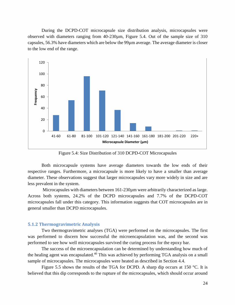
During the DCPD-COT microcapsule size distribution analysis, microcapsules were
observed with diameters ranging from 40-230µm, Figure 5.4. Out of the sample size of 310
capsules, 56.3% have diameters which are below the 99µm average. The average diameter is closer
to the low end of the range.
Figure 5.4: Size Distribution of 310 DCPD-COT Microcapsules
Both microcapsule systems have average diameters towards the low ends of their
respective ranges. Furthermore, a microcapsule is more likely to have a smaller than average
diameter. These observations suggest that larger microcapsules vary more widely in size and are
less prevalent in the system.
Microcapsules with diameters between 161-230µm were arbitrarily characterized as large.
Across both systems, 24.2% of the DCPD microcapsules and 7.7% of the DCPD-COT
microcapsules fall under this category. This information suggests that COT microcapsules are in
general smaller than DCPD microcapsules.
5.1.2 Thermogravimetric Analysis
Two thermogravimetric analyses (TGA) were performed on the microcapsules. The first
was performed to discern how successful the microencapsulation was, and the second was
performed to see how well microcapsules survived the curing process for the epoxy bar.
The success of the microencapsulation can be determined by understanding how much of
the healing agent was encapsulated.40 This was achieved by performing TGA analysis on a small
sample of microcapsules. The microcapsules were heated as described in Section 4.4.
Figure 5.5 shows the results of the TGA for DCPD. A sharp dip occurs at 150 °C. It is
believed that this dip corresponds to the rupture of the microcapsules, which should occur around
0
20
40
60
80
100
120
41-60 61-80 81-100 101-120 121-140 141-160 161-180 181-200 201-220 220+
Fre
qu
en
cy
Microcapsule Diameter (µm)

25
the boiling point of DCPD (170 °C with stabilizer). The mass lost before this sharp dip is
considered to result from the loss of material that had not been encapsulated. To analyze the change
in mass percent during the TGA, mass loss is calculated as a percent of the mass that is lost before
versus the mass lost during the degradation of the microcapsules. Approximately 7.5% of the initial
mass was burned off before the degradation of the microcapsules. The dip marking the degradation
of the microcapsules resulted in an 88% mass loss. It can therefore be concluded the over 90% of
the DCPD was encapsulated.
Figure 5.5: TGA of DCPD Microcapsules
Figure 5.6 shows the TGA for the DCPD-COT microcapsules. This microencapsulation
was even more successful than the DCPD. Only 2% is lost before degradation and over 91% after
the sharp dip, corresponding to 97% of the DCPD-COT was encapsulated.
0
0.1
0.2
0.3
0.4
0.5
0.6
0.7
0.8
0.9
1
0 100 200 300 400 500 600
Mas
s %
Temperature (°C)

26
Figure 5.6: TGA of DCPD-COT Microcapsules
TGA was also used to determine how well microcapsules endure the cure cycle. This was
tested by subjecting the microcapsules through the cure cycle temperatures over appropriate time
intervals and seeing how much mass was lost. First, the cure cycle of 120°C for two hours and
140°C for two hours was tested, Figure 5.7. This resulted in approximately 15% of the mass being
lost, likely through capsule rupture. The boiling point of DCPD with stabilizer is well over the
temperatures40, so it is suspected that the poly(urea-formaldehyde) degraded at these temperatures.
To prevent this mass loss during the production of the test bars, the cure cycle was reduced to 100
°C for two hours and 120 °C for two hours. The data for this cure cycle can be seen in Figure 5.8.
The mass loss from this cure cycle was only 3%, therefore this is the temperature regime that was
used for the epoxy bars.
0
0.1
0.2
0.3
0.4
0.5
0.6
0.7
0.8
0.9
1
0 100 200 300 400 500 600
Mas
s %
Temperature (°C)

27
Figure 5.7: TGA for Cure Cycle 1
Figure 5.8: TGA for Cure Cycle 2
5.2 Color Change Test
Before adding the microcapsules and Grubbs’ catalyst to the epoxy bars, the viability of
the color change system was tested. The DCPD-COT microcapsules were added to the Grubbs’
catalyst on a microscope slide. Another slide was then placed on top of the first slide and pushed
down to crush the microcapsules. The following pictures in Figure 5.9 convey this color change
over time.
100
110
120
130
140
150
160
0
10
20
30
40
50
60
70
80
90
100
0 50 100 150 200 250
Tem
pe
ratu
re (°C
)
Mas
s %
Time
80
90
100
110
120
130
140
0
10
20
30
40
50
60
70
80
90
100
0 30 60 90 120 150 180 210 240 270
Tem
pe
ratu
re (
°C)
Mas
s %
Time (min)

28
Figure 5.9: Time-Lapse of DCPD-COT Microcapsule Color Test
An immediate reaction at zero hours is not seen in the slide. However, liquid between the
slides could be seen, confirming that the microcapsules had been crushed. After one hour, the first
hint of a color change can be seen as the edges of the color spot seem to turn orange. The change
is more noticeable after 17 hours. The color is a more vibrant orange and in the center a purplish
color can be seen. From these pictures, it can be concluded that a color change occurred from the
COT reacting with the Grubbs’ catalyst.
A key goal of this project was to determine if the inclusion of COT in the microcapsule
system would inhibit the functionality of DCPD or vice versa. The test confirms that the presence

29
of DCPD in the microcapsules did not prevent COT from undergoing a color change when
combined with the Grubbs’ catalyst. A difference was observed between these results and the
reported color reaction that is supposed to take place instantaneously.3,4 Over an hour passed before
there was an indication of a change. This may be because the Grubbs’ catalyst had a layer of wax
protecting it and it took time for the COT to diffuse through the wax. Despite the longer than
expected time period, the COT successfully underwent the color change reaction. This verifies that
the wax protection is an effective method to prevent Grubb’s catalyst deactivation from exposure
to air while allowing it to retain functionality as catalyst for color changing reactions.
5.3 Production of Mechanical Testing Specimens
The specimens used for the modified compact tension testing were prepared by curing the
epoxy in a mold to produce a bar. The resultant epoxy bar was then machined into multiple
modified compact tension specimens as described in Section 4.7. During the process of producing
these specimens, differential scanning calorimetry (DSC) tests were performed to assess the
properties of the specimens. Several observations of the specimen material were also noted during
specimen production.
5.3.1 Differential Scanning Calorimetry Results
During preparation of the Cab-o-sil epoxy bar, a small sample of the uncured epoxy was
collected and tested using a DSC. While collecting heat flow data, the sample was heated from
ambient temperature to 250°C, then cooled to -50°C, then heated to 250°C once more, with heating
and cooling rates of 10°C per minute. The results of this test were plotted and are shown in Figure
5.10.
30
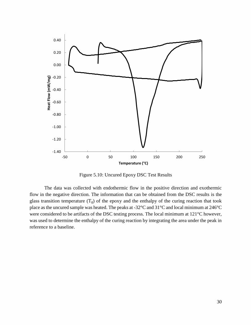
Figure 5.10: Uncured Epoxy DSC Test Results
The data was collected with endothermic flow in the positive direction and exothermic
flow in the negative direction. The information that can be obtained from the DSC results is the
glass transition temperature (Tg) of the epoxy and the enthalpy of the curing reaction that took
place as the uncured sample was heated. The peaks at -32°C and 31°C and local minimum at 246°C
were considered to be artifacts of the DSC testing process. The local minimum at 121°C however,
was used to determine the enthalpy of the curing reaction by integrating the area under the peak in
reference to a baseline.
-1.40
-1.20
-1.00
-0.80
-0.60
-0.40
-0.20
0.00
0.20
0.40
-50 0 50 100 150 200 250
He
at F
low
(m
W/m
g)
Temperature (°C)

31
Figure 5.11: Determination of Enthalpy of Curing Reaction for Uncured Epoxy
The DCS Netzsch software was used to determine the enthalpy of reaction. The enthalpy
is equal to the area under the peak relative to a base line, which is equal to the y-value at the point
where the area is taken to start. The enthalpy of reaction was found to be -425 J/g.
The Tg was determined by using the point of inflection on the near linear segment of the
curve with time values between 70 and 80 minutes.

32
Figure 5.12: Determination of Tg for Uncured Epoxy
The DCS Netzsch software was used to determine the Tg of the epoxy, which was found
to be 164.9°C. This value is consistent with the literature value for pure epoxy of 165°C.13
A similar DSC analysis was conducted for a small sample of the cured epoxy bar containing
only Cab-o-sil. The epoxy bar was cured under the same conditions as the DCPD and DCPD-COT
epoxy bars. Like the uncured epoxy sample, the sample was heated from ambient temperature to
250°C, then cooled to -50°C, then heated to 250°C once more, with heating and cooling rates of
10°C per minute. The results of this test are shown in Figure 5.13.

33
Figure 5.13: Cured Epoxy DSC Test Results
The peak that was used to determine the enthalpy of the curing reaction occurs at 149°C.
This peak is much smaller than the peak of the uncured sample because the enthalpy of the curing
reaction is much greater in the uncured sample, while the cured sample has already cured to a large
extent before the DCS testing has taken place.
-0.70
-0.50
-0.30
-0.10
0.10
0.30
0.50
-50 0 50 100 150 200 250
He
at F
low
(m
W/m
g)
Temperature (°C)
34
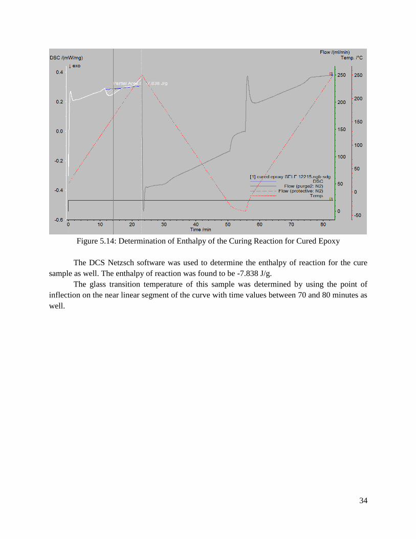
Figure 5.14: Determination of Enthalpy of the Curing Reaction for Cured Epoxy
The DCS Netzsch software was used to determine the enthalpy of reaction for the cure
sample as well. The enthalpy of reaction was found to be -7.838 J/g.
The glass transition temperature of this sample was determined by using the point of
inflection on the near linear segment of the curve with time values between 70 and 80 minutes as
well.
35
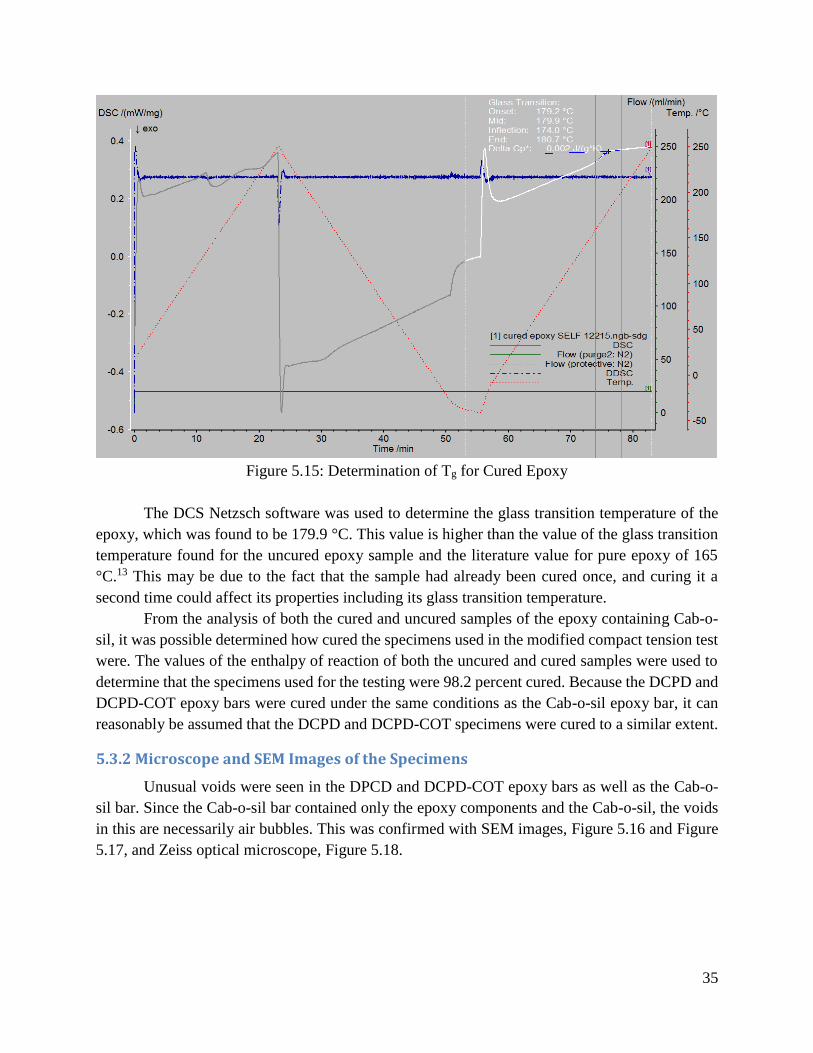
Figure 5.15: Determination of Tg for Cured Epoxy
The DCS Netzsch software was used to determine the glass transition temperature of the
epoxy, which was found to be 179.9 °C. This value is higher than the value of the glass transition
temperature found for the uncured epoxy sample and the literature value for pure epoxy of 165
°C.13 This may be due to the fact that the sample had already been cured once, and curing it a
second time could affect its properties including its glass transition temperature.
From the analysis of both the cured and uncured samples of the epoxy containing Cab-o-
sil, it was possible determined how cured the specimens used in the modified compact tension test
were. The values of the enthalpy of reaction of both the uncured and cured samples were used to
determine that the specimens used for the testing were 98.2 percent cured. Because the DCPD and
DCPD-COT epoxy bars were cured under the same conditions as the Cab-o-sil epoxy bar, it can
reasonably be assumed that the DCPD and DCPD-COT specimens were cured to a similar extent.
5.3.2 Microscope and SEM Images of the Specimens
Unusual voids were seen in the DPCD and DCPD-COT epoxy bars as well as the Cab-o-
sil bar. Since the Cab-o-sil bar contained only the epoxy components and the Cab-o-sil, the voids
in this are necessarily air bubbles. This was confirmed with SEM images, Figure 5.16 and Figure
5.17, and Zeiss optical microscope, Figure 5.18.

36
Figure 5.16: SEM Image of Cab-o-sil Surface
Figure 5.17: SEM Image of Cab-o-sil Surface

37
Figure 5.18: Optical Microscopy Image of Cab-o-sil Surface
These images provided a reference when looking at the DCPD and DCPD-COT epoxy
bars. The crack edge can be seen by the Zeiss optical microscope, Figure 5.19, and the SEM
images, Figure 5.20.
Figure 5.19: Voids and Microcapsules near DCPD Sample Crack Surface

38
Figure 5.20: SEM Image of DCPD Crack Edge
A number of spheres approximately 50-200 µm in size are visible near the crack surface in
Figure 5.19. Based on Cab-o-sil bar figures, it is believed some of these spheres are air bubbles.
However, it is certain that there were at least some microcapsules at the crack surface. It was
initially believed that the crack pinning seen in image Figure 5.19 was from the microcapsules but
the SEM image of the Cab-o-sil, Figure 5.17, also shows crack pinning characteristics.41 Figure
5.20 on the other hand, provides a definite image of a microcapsule. It is clearly seen that the
microcapsule has ruptured and polymerized at the crack surface.
5.3.3 Observations Made During Machining of the Specimens
During the production of the DCPD and DPCD-COT microcapsules, it was noted that
DCPD and COT produced very strong odors that make the compounds easily identifiable. This
strong smell is common among aromatic compounds. During the machining of the bars, it was
noted that the characteristic odors of DCPD and COT were present. This indicates that
microcapsules were being ruptured during the machining of the specimens. From this observation
it can be concluded that at least some of the microcapsules had remained intact during the curing
process.
Figure 5.21 shows a specimen of the DCPD bar that was prepared for the modified compact
tension test labeled D5 (left), and a specimen of the DCPD-COT bar that was prepared for the

39
modified compact tension test labeled C6 (right). The large voids and dark spots that are possible
indications of charring that occurred during the production of the epoxy bars can be seen in these
samples.
Figure 5.21: Specimens D5 and C6 Before Testing
5.4 Mechanical Testing The modified compact tension specimens were tested on the Instron with a loading rate of
0.1 mm/min, while load and displacement were recorded. An example of the raw data generated
this way can be seen in Figure 5.22.
Figure 5.22: Loading of DCPD-COT Specimen
0
20
40
60
80
100
120
140
0 0.1 0.2 0.3 0.4 0.5
Load
(N
)
Extension (mm)

40
The breaking force of the specimens ranged from approximately 88-120 N or 9-12 kgf. The
average breaking force the DCPD-COT specimens was 102.9 N ± 12.0 N and the average for the
DCPD specimens was 104.9 N ± 8.6 N. Figure 5.23 displays the average standard deviation for
each data set along with the minimum and maximum values obtained during testing. As was noted
above, the bars had significant voids in them so it is unknown how they would have performed
without such voids. From these results it can be concluded that the DCPD-COT and DCPD
specimens showed no significant difference in breaking strength, meaning the addition of COT
did not detract from the breaking strength of the specimens.
Figure 5.23: Breaking Force of Modified Compact Tension Specimens
The specimens broke into two pieces because the crack did not stop at the arresting hole.
The two pieces of the specimens were placed together and allowed to heal for twenty-four hours
under an aluminum plate to create low pressure healing conditions, 0.018 MPa.14 When checked
after the twenty-four hours, the specimens could not be picked up as a single piece. The specimens
did not heal along the crack. No color difference was seen after the twenty-four hour healing period
either.

41
Obstacles inhibiting sample healing include non-uniform dispersion and the presence of
voids. Both of these obstacles are characteristics that limit the proximity of the Grubbs’ catalyst
and microcapsules within the epoxy, making it less likely for self-healing mechanisms to occur.
Non-uniform dispersion and voids were most likely caused during the production of epoxy bars.
Non-uniform dispersion results in segregation of microcapsules and the Grubbs’ catalyst.
Both components of the self-healing system need to be in proximity with each other for the desired
reaction to occur. Dispersion is heavily influenced by the mixing cycle used to make epoxy bars,
so there should be an ideal mixing rate that is acceptable for this purpose. Under mixing causes
the components in the mixture to be inhomogenously dispersed throughout the epoxy. Over mixing
increases the chance that a significant portion of the microcapsules will rupture during the mixing
cycle. After mixing in all the components for the production of these bars, viscosities increased
noticeably. This increased viscosity may have made it more difficult for microcapsules to disperse
across the epoxy mixture resulting in a gradient of microcapsule concentration.
It is known through SEM imaging, Figure 5.20, that some polymerization occurred at the
crack surface. However, the specimens failed to heal. This could have been due to a lack of
components on the crack edge. Even if microcapsules were successfully dispersed throughout the
epoxy there might not have been enough microcapsules to promote significant healing at damage
sites to occur if too many of them ruptured during mixing. There were 3.7 g microcapsule and 10.1
g protected Grubbs’ catalyst per 100 mL epoxy. The ratio of microcapsule to epoxy and Grubbs’
catalyst to microcapsules fell within the optimal range of Brown et al.’ research on microcapsule
and catalyst loading.39 The Grubbs’ protection procedure may have also contributed to not having
enough of the active components on the crack edge. Healing agents within the microcapsules have
less access to the Grubbs’ catalyst after the Grubbs’ catalyst is coated in wax. There should be an
ideal ratio of wax relative to Grubbs’ catalyst that should be introduced in the system which
adequately protects the Grubbs’ catalyst but does not present too much of a barrier for diffusion of
healing agents. However, this ratio of wax is not known and any Grubbs’ catalyst at the crack edge
may not have been active enough for healing to occur.
The large voids could have prevented contact of the microcapsules and the Grubbs’
catalyst, therefore averting healing. It is believed that the voids seen in the DCPD and DCPD-COT
epoxy bars are pockets of conglomerated air bubbles which were observed in the Cab-o-sil bar,
see Section 5.3.2. The Cab-o-sil was added to the epoxy to act as a thixotropic agent, which enables
even dispersion of the components. However, it is now thought that the Cab-o-sil increased the
viscosity of the epoxy too much and prevented air bubbles from escaping during the thirty second
de-foaming step after being mixed in. When the components of the DCPD and DCPD-COT bars
were then mixed in at a slower mixing rate to prevent microcapsule rupture, the air bubbles in the
epoxy mixture conglomerated to form the large voids. In addition to having an impact on the
healing, these large voids also potentially had an impact on the mechanical properties of the
specimen.
42
6.0 Conclusions and Recommendations
6.1 Conclusions
Microcapsules were successfully created containing both a healing agent, DCPD, and a
damage detection agent, COT. When these microcapsules were ruptured in the presence of the
Grubbs’ catalyst, a color change was observed. Because the color change test was successful, it
can be concluded that DCPD-COT microcapsules could be used in place of DCPD microcapsules
in a self-healing polymer to provide damage detection.
DCPD microcapsules were added to epoxy in a ratio of 3.7 g microcapsules per 100 mL of
epoxy, which was then machined to produce modified compact tension specimens. DCPD-COT
specimens were produced in this way as well. The results of the mechanical testing showed that
the average breaking force of the DCPD modified compact tension specimens tested is 104.9 N ±
8.6 N. The average breaking force of the DCPD-COT modified compact tension specimens is
102.9 N ± 12.0 N. It can be concluded that the breaking force of the specimens tested was not
significantly affected by replacing DCPD microcapsules with DCPD-COT microcapsules. This
suggests that DCPD-COT microcapsules could be incorporated into a self-healing polymer in
place of DCPD microcapsules for the purpose of damage detection without significantly affecting
the polymer’s breaking strength.
No conclusion can be made about the effect of using DCPD-COT microcapsules in place
of DCPD microcapsules on the specimens’ healing efficiencies. This is because after testing the
DCPD and DCPD-COT modified compact tension specimens to determine their breaking forces,
the specimens were given 24 hours to heal. The specimens failed to heal during this time period,
and their healing efficiencies could not be tested
6.2 Recommendations
Some recommendations are provided based on the experience gained by working on this
project. First, it is recommended that the Grubbs-Love catalyst be used for better contrast. Despite
the small amount of Grubbs’ catalyst that was used in the epoxy specimens, 0.4 g unprotected per
100 mL epoxy, the distinct red color of the Grubbs’ catalyst was clearly present throughout the
specimen. The COT-Grubbs’ catalyst reaction also creates a red-purple color after long term
polymerization. Therefore, it is suggested that the Grubbs-Love catalyst be used, which is nearly
colorless, so that this reaction can be seen more clearly.
It is also recommended that more testing be conducted on the need for a thixotropic agent.
This testing should access if the curing of the epoxy resin with the amine curing agent is fast
enough that a thixotropic agent is not needed. It was observed that the addition of Cab-o-sil to the
epoxy mixture caused small air bubbles, which developed into large voids when more components
were added. If a thixotropic agent is needed, an agent other than Cab-o-sil should be picked.
Alternatively, a different mixing order or different mixing times/rates may be more effective.
The final recommendation is that more testing should be conducted on the amount of
microcapsules needed for a significant reaction with the Grubbs’ catalyst. It is possible healing
was not able to occur because of a lack of microcapsules to react with the Grubbs’ catalyst. More

43
testing should be easy to conduct with DCPD-COT microcapsules, since the reaction can be seen
visually.

44
Appendix
Appendix A: Microencapsulation Procedure
Adapted from the procedure of Brown et al.10
Microcapsules were prepared using an oil-in-water emulsion. A 500 mL beaker was placed
in a temperature controlled water bath. At room temperature, 100 mL of deionized water and 25
mL of 2.5 wt% aqueous solution of EMA copolymer were added and stirred with a mechanical
stirrer at 550 rpm. Under agitation, 2.50 g urea, 0.25 g ammonium chloride, and 0.25 g resorcinol
were added to the solution. The pH was raised from approximately 2.6 to 3.5 by drop-wise addition
of sodium hydroxide. One drop of 1-octanol was added to eliminate bubbles. Slowly, 30 ml of
DCPD was added and allowed to stabilize for 10 minutes. After 10 minutes, 6.33 g of 37 wt%
aqueous solution of formaldehyde was added. The emulsion was covered with aluminum foil and
heated to 55°C. After four hours of continuous stirring, the mixer and hot plate were switched off.
The suspension of microcapsules was separated under vacuum with a coarse filter. The
microcapsules were rinsed with deionized water and air dried for 24-48 h.
Appendix B: Grubbs’ Protection Procedure
Adapted from the procedure of Rule et al.21
Grubbs’ catalyst is very sensitive to air. Therefore, it needs to be protected before adding
it to an epoxy system. This can be done by encapsulating it in paraffin wax. In an N2-filled glove
box, the 0.5 grams Grubbs’ catalyst is added to a vial with 9.6 grams paraffin wax. An emulsion
was prepared in 1000 mL beaker with 225 mL of water, 0.63 g poly(ethylene-co-maleic
anhydride) (EMA copolymer), and one drop of 1-octanol. The emulsion was placed in an 82 °C
water bath and stirred with a mechanical stirrer at 900 rpm. The vial containing the wax and the
catalyst was submerged in the same 82 °C water bath. Once the wax was melted, approximately
10 minutes, it was shaken and poured into the emulsion. After 2 min, cold water (600 mL cooled
in the refrigerator) was quickly added, and the stirring was stopped. The microspheres were
collected by filtration and dried in the vacuum oven at room temperature.

45
References
1 Wu, D. Y.; Meure, S.; Solomon, D. Self-healing polymeric materials. Prog. Polym. Sci. 2008,
33, 479–522.
2 Pang, J.; Bond, I. P. A hollow fibre encompassing self-healing and enhanced damage visibility.
Compos. Sci. Technol. 2005, 65, 1791-1799.
3 Odom, S. A.; Jackson, A. C.; Prokup, A. M.; Chayanupatkul, S.; Sottos, N. R.; Moore, J. S.
Visual Indication of Mechanical Damage Using Core−Shell Microcapsules. ACS Appl. Mater.
Interfaces 2011, 3, 4547−4551
4 Odom, S. A., Caruso, M. M., Finke, A. D., Jackson, A. C., Moore, J. S., Sottos, N. R., & White,
S. R. System for visual indication of mechanical damage. U.S. Patent 8,846,404, September 30,
2014.
5 Blaiszik, B. J.; Kramer, S. L. B.; Olugebefola, S. C.; Moore, J. S.;. Sottos, N. R; White, S. R.
Self-Healing Polymers and Composites. Materials Research 2010. 179-211.
6 Zhang, M. Q.; Rong, M. Z Self- Healing Polymers and Polymer Composites, EngineeringPro
2011.
7 Toohey, K. S.; Hansen, C. J.; Lewis, J. A.; White, S. R., Sottos, N. R. Delivery of Two- Part
Self-Healing Chemistry via Microvascular Networks. Advanced Functional Materials 2009.
8 Hayes, S. A.; Zhang, W.; Branthwaite, M.; Jones, F.R. Self-healing of damage in fiber-
reinforced polymer-matrix composites. J. R. Soc. Interface. 2001 4, 381-387
9 Bergman, S. D.; Wudl, F.; Mendable Polymers. J. Mater. Chem., 2008,18, 41-62
10 Brown, E. N.; Kessler, M. R.; Sottos, N. R.; White, S. R. In situ poly(urea-formaldehyde)
microencapsulation of dicyclopentadiene. Journal of Microencapsulation 2003.
11 Rochmadi; Prasetya A.; Hasokowati W. Mechanism of Microencapsulation with Urea-
Formaldehyde Polymer. American Journal of Applied Sciences 2010, 739-745, 1546-9239.
12 White, S. R.; Sottos, N. R.; Geubelle, P. H.; Moore, J. S.; Kessler, M. R.; Sriram, S. R.;
Brown, E. N.; Viswanathan, S. Autonomic healing of polymer composites. Nature 2001, 794-
797.
13 Park, E.; Park, J.; Jeon, J.; Sung, J.; Hwang, W.; Lee, B. Ring-opening metathesis
polymerization of dicyclopentadiene and tricyclopentadiene. Macromolecular Research 2012.

46
14 Rahmathullah, M.; Palmese, G. Crack-Healing Behavior of Epoxy–Amine Thermosets.
Journal of Applied Polymer Science 2009. 113, 2191–2201.
15 Dorworth, L. Proceedings from SAMPE '09: Society for Advancement on Materials and
Process Engineering Conference. Baltimore, 2009.
16 Grubbs, R. H. Olefin Metathesis. Tetrahedron 2004, 7117-7140, 0040-4020.
17 Schubert, U. Advances in Metal Carbene Chemistry, NATO ASI Series, 1989.
18 Leitgeb, A.; Wappel, J.; Slugovc, C. The ROMP toolbox upgraded. Polymer 2010, 2927-2946,
0032-3861.
19 Blaiszik, B.J.; Sottos, N.R.; White, S.R. Nanocapsules for self-healing materials. Composites
Science and Technology 2008, 978-986, 0266-3538.
20 Rochmadi; Prasetya A.; Hasokowati W. Mechanism of Microencapsulation with Urea-
Formaldehyde Polymer. American Journal of Applied Sciences 2010, 739-745, 1546-9239.
21 Rule, J. D., Brown, E. N., Sottos, N. R., White, S. R., & Moore, J. S. Wax‐Protected Catalyst
Microspheres for Efficient Self‐Healing Materials. Advanced Materials 2005, 17, 205-208.
22 Pham, H. Q.; Marks, M. J. Epoxy Resins. Kirk-Othmer Encyclopedia of Chemical Technology,
2004.
23 Ratna, D. Handbook of Thermoset Resins, Smithers Rapra Technology, 2009.
24 Lee, J. K.; Hong, S. J.; Liu, X.; Yoon, S. H. Characterization of dicyclopentadiene and 5-
ethylidene-2-norbornene as self-healing agents. Macromolecular Research 2004, 10, 478-483.
25 Noh, H.H.; Lee, J.K. Microencapsulation of self-healing agents containing a fluorescent
dye. 2012, 9.
26 Toohey, K. S.; Hansen, C. J.; Lewis, J. A.; White S. R.; Sottos N. R. Delivery of Two-
Part Self-Healing Chemistry via Microvascular Networks. Advanced Functional Materials
2009, 19, 1339-1405.
27 Li, H.; Wang, R.; Liu, W. Surface modification of self-healing poly(urea-formaldehyde)
microcapsules using silane-coupling agent. Applied Surface Science 2008, 255, 1894–1900.
28 Bains, G. K.; Kim, S. H.; Sorin, E. J.; Narayanaswami, V. The Extent of Pyrene Excimer
Fluorescence Emission Is a Reflector of Distance and Flexibility. Am. Chem. Soc. 2012, 51,
6207–6219.
29 Turro, N. J.; Arora, K. S.; Pyrene as a photophysical probe for intermolecular interactions.
Polymer 1986, 27.

47
30 Bogan, G.W; The Dow Chemical Company. Unique polyaromatic cyanate ester
for low dielectric printed circuit boards. SAMPE Journal 1988; 24 (6): 19-25.
31 Liaw, D. Pyrene-containing norbornene methylene amine and polymer thereof, and method for
manufacturing the polymer. 2011, 113.
32 Jimenez, I. Y.; Bartha, R. Solvent-Augmented Mineralization of Pyrene. Appl. Environ.
Microbiol. 1996, 62, 2311-2316.
33 McIllroy, D. A.; Blaiszik, B. J.; Caruso, M. M.; White, S. R.; Moore, J. S.; Sottos, N. R.
Microencapsulation of a Reactive Liquid-Phase Amine for Self-Healing Epoxy Composites.
Macromolecules 2010, 43, 1855–1859.
34 Bleay, S. M.; Loader, C. B.; Hawyes, V. J.; Humberstone, L.; Curtis, P. T. A smart repair
system for polymer matrix composites. Composites, Part A 2001, 31, 1767-1776.
35 Klinga, S.; Czigánya, T. Damage detection and self-repair in hollow glass fiber epoxy
composite. Compos. Sci. Technol. 2014, 99, 82-88.
36 Bruns, N.; Pustelny1, K.; Bergeron, L. M.; Whitehead, T. A.; Clark, D. S. Mechanical
Nanosensor Based on FRET within a Thermosome. Angew. Chem., Int. Ed. 2009, 48, 5666-5669.
37 Makyła, K.; Müller, C.; Lörcher, S.; Winkler, T.; Nussbaumer, M. G.; Eder, M.; Bruns, N.
Fluorescent Protein Senses and Reports Mechanical Damage. Advanced Materials 2013, 25,
2701-2706.
38 Löwe, C.; Weder, C. Excimers as Molecular Probes: Deformation-Induced Color Changes.
Advanced Materials 2002, 14, 1625-1629.
39 Brown, E. N.; Sottos, N. R.; White, S. R. Fracture testing of a self-healing polymer composite.
Experimental Mechanics 2002, 42, 372-379
40 Dicyclopentadiene ; MSDS No. AC150760000 [Online]; Fisher Scientific: Fair Lawn, NJ ,
May 20, 2010. (accessed Feb 11, 2015).
41 Chaudhary, S., Parthasarathy, S., Kumar, D., Rajagopal, C., & Roy, P. Simple toughening of
epoxy thermosets by preformed thermoplastics. Society of Plastics Engineers 2014.


