Embed Size (px)
Citation preview
University of WollongongResearch Online
Faculty of Engineering and Information Sciences -Papers: Part A Faculty of Engineering and Information Sciences
2017
Development of microencapsulated phase changematerial for solar thermal energy storageWeiguang SuUniversity of Nottingham, Qilu University of Technology
Jo DarkwaUniversity of Nottingham
Georgios KokogiannakisUniversity of Wollongong, [email protected]
Research Online is the open access institutional repository for the University of Wollongong. For further information contact the UOW Library:[email protected]
Publication DetailsSu, W., Darkwa, J. & Kokogiannakis, G. (2017). Development of microencapsulated phase change material for solar thermal energystorage. Applied Thermal Engineering, 112 1205-1212.

Development of microencapsulated phase change material for solarthermal energy storage
AbstractIn this paper a novel microencapsulated phase change material (MF-3) has been developed and tested forsolar assisted hot water storage systems. Even though the morphology of the sample was affected by the typeof emulsifier used for fabrication it recorded the highest energy storage capacity of 126 kJ/kg withencapsulation efficiency of 97.4% as compared with other developed samples. For the purpose of assessing itsthermal effectiveness it was theoretically evaluated in a compacted fixed bed TES unit and found to be capableof achieving a higher energy storage density as well as relatively smaller physical storage size than water basedsystem. Despite the overall effective thermal conductivity being slightly less than water, its value was stillabout twice as high as most current PCM storage units. Experimental evaluation is therefore stronglyencouraged.
Keywordsthermal, solar, storage, material, energy, change, phase, microencapsulated, development
DisciplinesEngineering | Science and Technology Studies
Publication DetailsSu, W., Darkwa, J. & Kokogiannakis, G. (2017). Development of microencapsulated phase change material forsolar thermal energy storage. Applied Thermal Engineering, 112 1205-1212.
This journal article is available at Research Online: http://ro.uow.edu.au/eispapers/6317

1
Development of microencapsulated phase change
material for solar thermal energy storage
Weiguang Su1,a, Jo Darkwa2, Georgios Kokogiannakis3
1. School of Mechanical & Automotive Engineering, Qilu University of Technology, Jinan,
China
2. Faculty of Engineering, University of Nottingham, UK
3. Sustainable Buildings Research Centre, University of Wollongong, Australia
Nomenclature
, , the specific heat of water, core material and shell material
latent heat of PCM
enthalpy
, , the conductivity of water, paraffin and shell material
, , the weight percentage of water, core material and shell material
the weight percentages of MEPCM in TES unit
, , the volume percentage of water, shell material and core material
the temperature difference
the core material content of MEPCM
a Corresponding author. E-mail address: [email protected]

2
1 Introduction
Solar thermal energy storage (TES) systems are considered to be among the commonest methods
of providing hot water or space heating services in buildings due to their relatively lower cost and
ease of operation [1-3]. For instance, a seasonal solar TES water tank was used to improve the
energy performance of district heating/cooling and hot water supply systems by Tanaka et al [4].
Furbo et al.[5] developed a smart solar TES tank for a small solar domestic hot water system,
which can be heated both by solar collectors and by means of an auxiliary energy supply system.
The investigations showed that the yearly thermal performance of the smart solar system was
5–35% higher than traditional system. However, the TES tanks do experience buoyancy
dependent stratification which tends to affect their heat transfer processes [6-8]. They also tend
to be relatively bulky and occupy more useable space[9]. To this end, Morrison et al. [8] have
investigated the use of mantle heat exchangers as means of degrading thermal stratification in
TES tanks and thereby enhancing the thermal performance of solar water heating systems.
Various researchers have also explored the possibility of using phase change materials (PCMs) as
heat storage media since they have much higher energy storage capacity and energy storage
density than water [2, 10-13]. For instance, Murray and Groulx [10] evaluated a PCM based TES
system and achieved about 44.3% increase in energy storage density as compared with water
based system. Similar investigation carried out by Delgado et al.[13] with PCM emulsion, also
achieved an increase of 34% in energy storage capacity as against water based TES system.

3
However, PCMs generally possess low thermal conductivity and hence poor thermal response
factor. For example the study by López-Navarro et al. [14] showed a declining thermal response
factor in a PCM storage tank after a few number of thermal cycling and was attributed to low
thermal conductivity of the PCM. Other general weakness in PCMs is instability in their melting
temperatures during long term storage operation. This phenomena was evident in a study by
Behzadi [15] when the melting temperature of the PCM shifted from 21 to 28℃ after 120
repeated thermal cycles. Apart from thermal instability issue, Chen et al. [16] also observed a
high level of thermal stress in a PCM storage tank as a result of considerable change in density
during phase transition period.
In order to overcome some of these problems the study was primarily focused on the
development of a novel high temperature microencapsulated phase change material (MEPCM)
for application in a compacted water saturated fixed bed system [12] as shown in Fig. 1. This
storage unit has the potential of achieving much higher effective thermal conductivity, enhanced
thermal stability and higher energy storage density with a relatively smaller physical storage size
than conventional water storage tanks.

4
2 Development of MEPCM
2.1 Material selection
Paraffin wax with a melting temperature of 48℃ was chosen as the base material for the
development of the MEPCM because of its relatively high latent heat capacity and phase change
temperature. Melamine-formaldehyde (MF) resins have been widely used as shell materials for
encapsulation processes due to their ability to be crosslinked at different
melamine/formaldehyde molecular ratios such as: 1:1.25-2 [17], 1:2.66 [18] and 1:2.5 [19]).
Therefore melamine with 99% purity level and 37 wt% formaldehyde solution was used as shell
monomers. Two types of emulsifiers i.e. Sodium dodecyl sulfate (SDS; Sinopharm Chemical
Reagent Co.,Ltd, China; purity 90%) and binary emulsifier Brij 30 (Aladdin, Japan) & Brij 58 (Sigma,
USA) were used to evaluate the effect of emulsifiers on the developed MEPCM. Citric acid
(Sinopharm Chemical Reagent Co.,Ltd, China) and sodium hydroxide (Sinopharm Chemical
Reagent Co.,Ltd, China) solution were used to control the pH values during the experimental
process. Ammonium chloride (purity 99.5%) also supplied by Sinopharm Chemical Reagent
Co.,Ltd. was used as a nucleation agent whereas deionized water was applied for dilution
processes. Table 1 shows a summary and composition of basic materials that were used for the
development of the MEPCM samples (MF-1, MF-2, MF-3, MF-4 and MF-5).

5
2.2 Fabrication of MEPCM
The fabrication of the MEPCM samples was based on in-situ polymerization method as well as
processes covering synthesisation of prepolymer solution, preparation of oil-in-water (O/W)
emulsion and formation of shells. The value of hydrophilic–lipophilic balance (HLB) [20] of
emulsifier is one of the most important factors for preparing a stable oil-in-water (O/W) emulsion.
Meanwhile, the average HLB value for the nonionic binary emulsifier can be calculated according
to the weight percentages and HLB values of the initial components [21]. Therefore Brij 30 and
Brij 58 were mixed together at an appropriate HLB value of 12 to prepare for the O/W emulsion.
As shown in Fig. 2, melamine (4.04g) and 37% formaldehyde solution (6.5g) were initially mixed
with 10ml deionized water at a stirring speed of 200 rpm. It was then heated up to 70°C and
maintained at that reaction temperature until the suspension became transparent. The
prepolymer solution was prepared at a pH value of 8.5–9 with 0.2wt% sodium hydroxide solution.
The next stage of the fabrication process involved mixing together the molten paraffin with
denoized water and the emulsifiers. The solution was then stirred at a speed of 7000rpm for
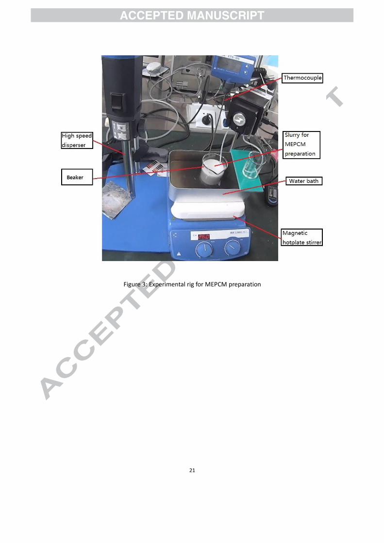
10min with a dispersion machine (IKA T18, Germany, see Fig.3) to obtain a stable O/W emulsion.
In order to fabricate the MEPCM, the capsules need to crosslink with MF polymer at a lower pH
value ranging from 3-5 as shown in the fabrication flow chart. For this reason the pH value of the
mixture was modified to 3–4 with 5wt% citric acid solution to initiate the crosslinking process.
Meanwhile the prepolymer solution was added to the O/W emulsion at a stirring speed of 300

6
rpm with a magnetic stirrer (type IKA HS-7, Germany, see Fig.3) for 4 hours at a temperature of
70°C. The end product was finally filtered, washed with water and then dried in an oven at a
temperature of 60°C for 20 hours.
3 Results and analysis
3.1 Evaluation of fabricated MEPCM samples
3.1.1 Scanning electron microscopy (SEM) analysis
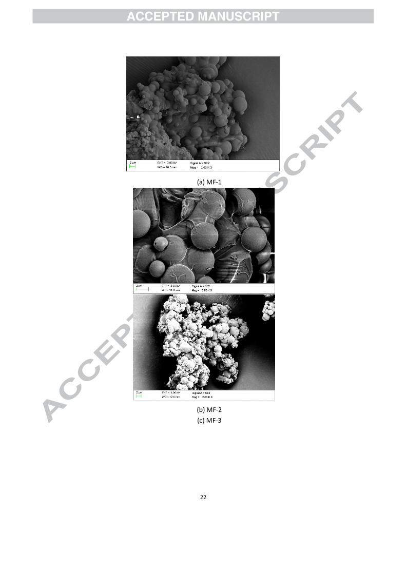
A scanning electron microscope (SEM) by Sigma VP, Carl Zeiss Co. Ltd., was used to examine the
morphologies of the fabricated MEPCM samples. Since the shell material is a non-conductive
material, the samples were initially coated with 5 nm thick gold layer in order to increase their
electrical conductivity before the microscopy analysis was carried out. This procedure was in
accordance with a similar study carried out by Suzuki [22].
As shown in Fig. 4, the particles sizes of the samples were similar in sizes measuring about 2µm
but there were significant differences in their morphologies which were attributed to different
HLB values for the emulsifiers used for the encapsulation process. For instance the HLB value for
the anionic SDS emulsifier used for samples MF-1, MF-2 and MF-3 (Fig. 4a to Fig. 4c) was as high
as 40 which resulted in the agglomeration of the particles. On the other hand the MF-4 and MF-5
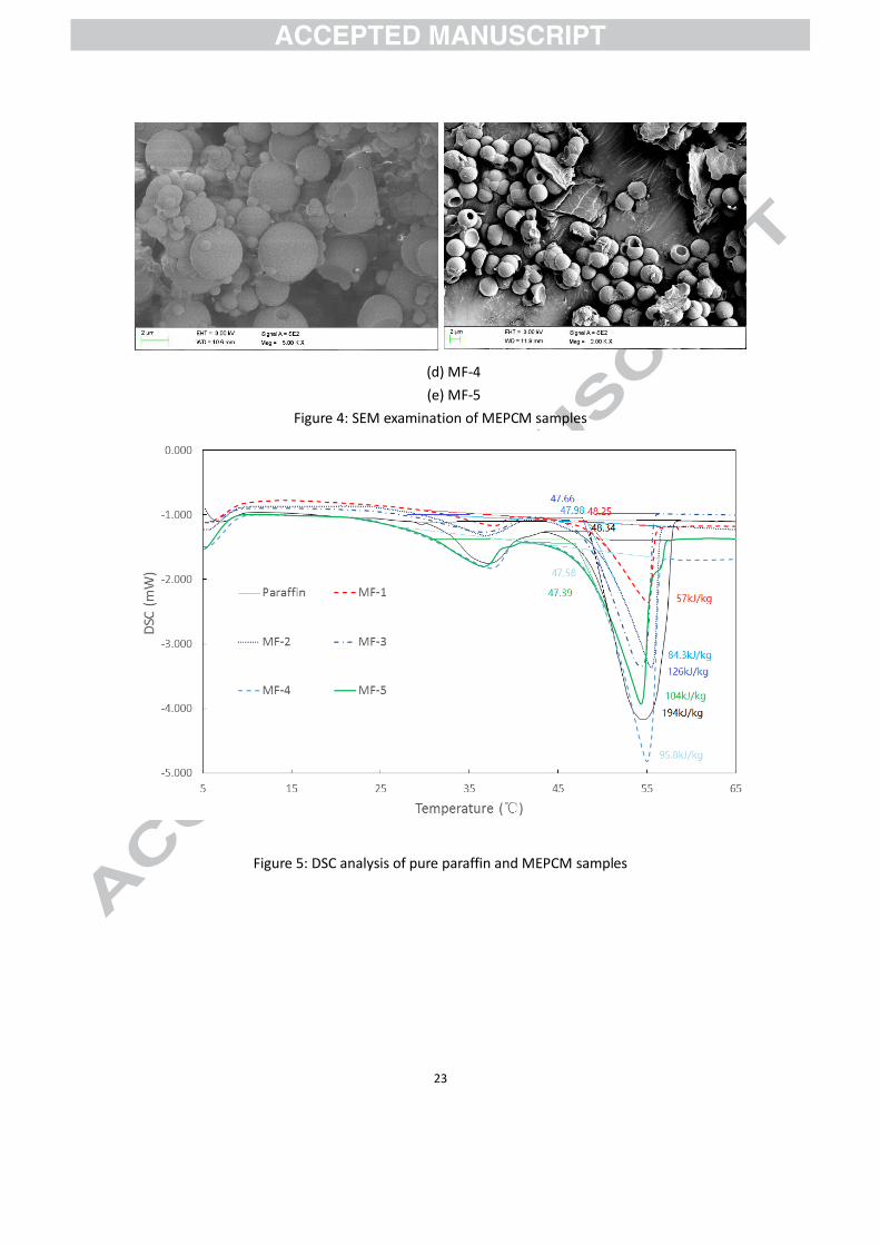
samples (Fig. 4d and Fig. 4e) achieved much better morphologies with a lower HLB value of 12 for

7
the binary emulsifiers (Brij 30 and Brij 58). In general emulsifiers are used for reducing interfacial
tension in O/W emulsions and to prevent coalescence by capsules adsorption onto the oil/water
interface in order to promote the formation of regular shapes of capsules during
microencapsulation process. It is obvious from the outcomes that the binary emulsifiers were
more effective than the SDS emulsifier due to the synergy of the two emulsifiers [23] hence.
3.1.2 Energy storage capacity, melting temperature and encapsulation
efficiency
A differential scanning calorimetric (DSC6220, SII Nanotechnology) equipment was used in
determining the enthalpies of fusion and melting temperature of the MEPCM samples in
accordance with ISO 11357 Standards under the dynamic testing method. The samples were
tested at atmospheric pressure and at a heating rate of 2 °C /min from 5℃ to 65℃.
As shown in Fig. 5 and in relation to the pure paraffin, sample MF-3 achieved the highest melting
enthalpy of 126 kJ/kg as against 57 kJ/kg, 84.3kJ/kg, 95.8 kJ/kg and 104 kJ/kg for MF-1, MF-2,
MF-4 and MF-5 respectively. With regard to their melting temperatures, there was no strong
evidence to suggest that the organic emulsifiers had any major effect on the samples since there
was only a slight reduction of between 0.08℃ to 0.95℃ as summarized in Tab. 2. The DSC results
were also used to determine the encapsulation efficiency which is defined as the ratio of the
actual core content of the microcapsules to the theoretical core content [24]. The percentages of
8
core material contents for the samples were therefore obtained as 29% for MF-1, 43% for MF-2,
65% for MF-3 49% for MF-4 and 54% for MF-5. Now based on the initial core/shell weight ratios
in Tab. 1, the corresponding encapsulation efficiencies were obtained as 44.23%, 65.18%, 97.42%,
74.07% and 80.41%.
Beside the morphology the type of emulsifiers also demonstrated some effects on the core
material content and encapsulation efficiency for the fabricated MEPCM samples. For instance,
the core material content for sample MF-4 (49%) was much higher than sample MF-1 (29%) due
to the effect of the binary emulsifier. However, comparison of MF-5 and MF-3 shows that the
core material content was reduced about 11% by the binary emulsifier, which was attributed to
the fact that some of the capsules in MF-5 were not fully encapsulated.
The results as summarised in Tab. 2 show that the nucleating agent (ammonium chloride) did
also influence the core material content and the encapsulation efficiencies of the MEPCM
samples. For instance the core material content and the encapsulation efficiency for MF-3 did
increase by more than 35% and 53% respectively with 0.25g of ammonium chloride as a
nucleation agent. Meanwhile, the core material content and the encapsulation efficiency of MF-5
also increased by 5%-6% thus showing the positive effect of nucleating agent when the binary
emulsifiers were used to prepare the MEPCM samples. This is based on the fact that ammonium
chloride as nucleating agent can effectively reduce the pH value [25] during the polymerization
reaction.

9
3.1.3 Thermal stability
Thermogravimetric (TG) technique can be used to analyse the thermal stability of a sample
material by measuring the amount of weight change of the material as a function of increasing
temperature in a controlled atmosphere of nitrogen, helium, air, or in vacuum, which exhibits loss
or gain of mass due to thermal decomposition, evaporation, oxidation or dehydration of the
sample [26]. The thermal stabilities of the MEPCM samples were therefore examined under
nitrogen gas protection covering a heating range of 50℃ to 500℃ and at a heating rate of
10℃/min. As presented in Fig. 6, the maximum weight loss temperatures for the samples were as
high as 283.7℃, 280.1℃, 279.7℃, 283℃ and 272.2℃ for MF-1, MF-2, MF-3, MF-4 and MF-5
respectively as compared with 238℃ for the pure paraffin. It should also be noted that in general
higher core material content does affect the thermal stability of capsules thus confirming why
MF-5 achieved the lowest weight loss temperature. Even though the shell material of the
samples has a lower melting point temperature of 180℃ than the corresponding weight loss
temperatures, it is far more higher than the temperature requirement for hot water (29–60℃)
[27] or space heating (30-65℃) [28] services in buildings. In addition the shell material can
protect the core material from the influences of the outside environment and to maintain
temperature stability for long term TES application. Above all the MF shell can accommodate
changes in volume during phase change process of the core material thereby decreasing the
thermal stress in TES tanks. Therefore, the long term operational thermal stability of the latent

10
heat storage media for the proposed TES unit can be improved by using the developed MEPCM.
3.2 Theoretical evaluation of proposed TES unit
As described in Fig. 1, the TES unit is similar to the concept adopted for enhancing energy storage
density and effective thermal conductivity in a study conducted by Darkwa et al. [29]. Therefore
by considering individual elements and their weight proportions the various percentages of
energy storage capacity may be calculated using Eq. 1 below as:
(1)
(2)
(3)
(4)
So that Eq.1 becomes:
(5)
Where
, and are the weight percentages of water, core material and shell material
respectively, %.

11
, and are the corresponding specific heat capacities, J/kg∙℃.
, , and are the corresponding densities, kg/m3.
is the latent heat of PCM, kJ/kg.
is the temperature difference, ℃.
is the weight percentages of MEPCM in TES unit, %.
is the core material content of MEPCM, %.
The effective thermal conductivity can also be calculated by considering the conductivity and the
volume fraction of each component as established by Thiele et al. [30] and reported by Felske [31]
in Eq. 6 as:
(6)
(7)
(8)
According to Eq.2-4, Eq.7 becomes:

12
(9)
By the same method,
(10)
Where
, and are the conductivities of water, paraffin and shell material, W/m∙K.
and are the volume percentages of water, shell material and core material, %.
Now using sample MF-3 and the data in Tab. 3, the energy storage density and the effective
thermal conductivity of the TES unit over a range of 40 to 60 ℃ with different weight percentage
of MPECM can be calculated and represented graphically in Fig. 7.
Analysis of the results show that energy storage density increases with weight percentage of the
MEPCM whilst effective thermal conductivity reduces. For instance if 50 wt% MEPCM is to be
used in the proposed TES unit, its energy storage density would increase from 84000 kJ/m3 to
128735 kJ/m3. It would also reduce the volume of the TES unit by about 34.7% in comparison
with a water storage tank of the same energy storage capacity. Even though the effective thermal
13
conductivity of (ke1) would reduce to 0.41 W/m∙K, it is still about 2 times that of pure paraffin. In
comparison with other studies, the effective conductivity of the developed MEPCM is much
higher than other thermal energy storage materials, such as lauric acid (0.148~0.150 W/m∙K) [10],
PCM emulsion (0.27 W/m∙K) [13], RT8 (0.20 W/m∙K) [14] and Rubitherm 21 (0.20 W/m∙K) [15].
Previous investigations also showed that thermal response time of TES units were poor due to
low thermal conductivity of the phase change materials. For instance the experimental results by
Murray and Groulx [10] showed that the time requirements for thermal energy charging and
discharging in a TES system were as long as 30 hours and 32 hours respectively. The thermal
response of the proposed TES unit is therefore expected to be much higher during thermal
energy charging/discharging cycling. There is however the need for the TES unit to be optimized
based on design and operational requirements.
4 Conclusions
The study was focused on the development of a high melting temperature MEPCM for solar hot
water storage system. Five MEPCM samples (MF-1, MF-2, MF-3, MF-4 and MF-5) have therefore
been successfully fabricated through in-situ polymerization method. Analysis of the results
showed that MF-3 achieved the highest enthalpy of 126 kJ/kg but there was no huge difference
in their melting temperatures which was ranged between 0.08℃ to 0.95℃. In general the overall

14
thermal stability of the samples was relatively high with MF-3 reaching 279.7℃. The
encapsulation efficiency was however influenced by the nucleation agent whilst the morphology
was also affected by the type of emulsifier since samples MF-4 and MF-5 achieved much better
morphology with the binary emulsifier than samples MF-1, MF-2 and MF-3 which were fabricated
with SDS emulsifier. In order to assess their thermal effectiveness, MF-3 was theoretically
evaluated in an integrated compacted fixed bed unit and found to be capable of contributing to a
system with higher energy storage density and relatively smaller physical storage size than water
based system. Even though the overall effective thermal conductivity of the unit was slightly less
than water, it was found to be about twice as high as most current PCM storage units. The
proposed TES unit is therefore expected to be thermally more responsive during thermal energy
charging/discharging process. Experimental evaluation is therefore being encouraged towards
achieving a workable prototype.
Reference
[1] J.F. Belmonte, P. Eguía, A.E. Molina, J.A. Almendros-Ibáñez, R. Salgado, A simplified method for
modeling the thermal performance of storage tanks containing PCMs, Applied Thermal Engineering,
95 (2016) 394-410.
[2] S. Seddegh, X. Wang, A.D. Henderson, Z. Xing, Solar domestic hot water systems using latent heat
energy storage medium: A review, Renewable and Sustainable Energy Reviews, 49 (2015) 517-533.
[3] M. Thirugnanasambandam, S. Iniyan, R. Goic, A review of solar thermal technologies, Renewable
and Sustainable Energy Reviews, 14 (2010) 312-322.

15
[4] H. Tanaka, T. Tomita, M. Okumiya, Feasibility study of a district energy system with seasonal water
thermal storage, Solar Energy, 69 (2000) 535-547.
[5] S. Furbo, E. Andersen, S. Knudsen, N.K. Vejen, L.J. Shah, Smart solar tanks for small solar domestic
hot water systems, Solar Energy, 78 (2005) 269-279.
[6] H.Ö. Paksoy, Thermal energy storage for sustainable energy consumption fundamentals, case
studies and design, Springer, Dordrecht :, 2007.
[7] M. Raisul Islam, K. Sumathy, S. Ullah Khan, Solar water heating systems and their market trends,
Renewable and Sustainable Energy Reviews, 17 (2013) 1-25.
[8] G.L. Morrison, A. Nasr, M. Behnia, G. Rosengarten, Analysis of horizontal mantle heat exchangers in
solar water heating systems, Solar Energy, 64 (1998) 19-31.
[9] J. Xu, R.Z. Wang, Y. Li, A review of available technologies for seasonal thermal energy storage, Solar
Energy, 103 (2014) 610-638.
[10] R.E. Murray, D. Groulx, Experimental study of the phase change and energy characteristics inside
a cylindrical latent heat energy storage system: Part 1 consecutive charging and discharging,
Renewable Energy, 62 (2014) 571-581.
[11] D.N. Nkwetta, F. Haghighat, Thermal energy storage with phase change material—A state-of-the
art review, Sustainable Cities and Society, 10 (2014) 87-100.
[12] M.K.A. Sharif, A.A. Al-Abidi, S. Mat, K. Sopian, M.H. Ruslan, M.Y. Sulaiman, M.A.M. Rosli, Review of
the application of phase change material for heating and domestic hot water systems, Renewable and
Sustainable Energy Reviews, 42 (2015) 557-568.
[13] M. Delgado, A. Lázaro, J. Mazo, C. Peñalosa, P. Dolado, B. Zalba, Experimental analysis of a low
cost phase change material emulsion for its use as thermal storage system, Energy Conversion and
Management, 106 (2015) 201-212.
[14] A. López-Navarro, J. Biosca-Taronger, J.M. Corberán, C. Peñalosa, A. Lázaro, P. Dolado, J. Payá,
Performance characterization of a PCM storage tank, Applied Energy, 119 (2014) 151-162.
[15] S. Behzadi, M.M. Farid, Long term thermal stability of organic PCMs, Applied Energy, 122 (2014)
11-16.
[16] S.-L. Chen, C.-L. Chen, C.-C. Tin, T.-S. Lee, M.-C. Ke, An experimental investigation of cold storage
16
in an encapsulated thermal storage tank, Experimental Thermal and Fluid Science, 23 (2000) 133-144.
[17] F. Cao, B. Yang, Supercooling suppression of microencapsulated phase change materials by
optimizing shell composition and structure, Applied Energy, 113 (2014) 1512-1518.
[18] J.K. Choi, J.G. Lee, J.H. Kim, H.S. Yang, Preparation of microcapsules containing phase change
materials as heat transfer media by in-situ polymerization, Journal of Industrial and Engineering
Chemistry, 7 (2001) 358-362.
[19] K. Hong, S. Park, Melamine resin microcapsules containing fragrant oil: synthesis and
characterization, Materials Chemistry and Physics, 58 (1999) 128-131.
[20] T.F. Tadros, Emulsion Science and Technology, Wiley, 2009.
[21] W.C. Griffin, Calculation of HLB valuess of Nonionic Surfactants, J. Soc. Cosmet. Chem, 5 (1954)
249-256.
[22] E. Suzuki, High-resolution scanning electron microscopy of immunogold-labelled cells by the use
of thin plasma coating of osmium, Journal of Microscopy, 208 (2002) 153-157.
[23] M.J. Rosen, Predicting synergism in binary mixtures of surfactants, in: M.J. Schwuger, F.H. Haegel
(eds.) Surfactants and Colloids in the Environment, Steinkopff, Darmstadt, 1994, pp. 39-47.
[24] H. Zhang, X. Wang, Synthesis and properties of microencapsulated n-octadecane with polyurea
shells containing different soft segments for heat energy storage and thermal regulation, Solar Energy
Materials and Solar Cells, 93 (2009) 1366-1376.
[25] I.S. Chuang, G.E. Maciel, Carbon-13 CP/MAS NMR study of the structural dependence of
urea-formaldehyde resins on formaldehyde-to-urea molar ratios at different urea concentrations and
pH values, Macromolecules, 25 (1992) 3204-3226.
[26] M.E. Brown, INTRODUCTION TO THERMAL ANALYSIS: Techniques and Applications, Springer,
Netherlands, 2001.
[27] W. Su, J. Darkwa, G. Kokogiannakis, Review of solid–liquid phase change materials and their
encapsulation technologies, Renewable and Sustainable Energy Reviews, 48 (2015) 373-391.
[28] D. Feldman, M.M. Shapiro, D. Banu, C.J. Fuks, Fatty acids and their mixtures as phase-change
materials for thermal energy storage, Solar Energy Materials, 18 (1989) 201-216.

17
[29] J. Darkwa, O. Su, T. Zhou, Development of non-deform micro-encapsulated phase change energy
storage tablets, Applied Energy, 98 (2012) 441-447.
[30] A.M. Thiele, A. Kumar, G. Sant, L. Pilon, Effective thermal conductivity of three-component
composites containing spherical capsules, International Journal of Heat and Mass Transfer, 73 (2014)
177-185.
[31] J.D. Felske, Effective thermal conductivity of composite spheres in a continuous medium with
contact resistance, International Journal of Heat and Mass Transfer, 47 (2004) 3453-3461.

18
Table 1: Materials for MEPCM fabrication
Table 2: Thermal properties of paraffin and MEPCM samples
Table 3: Thermophysical properties of TES components
Figure 1: Compacted MEPCM bed system for solar TES system
Figure 2: MEPCM fabrication procedure [17-19]
Figure 3: Experimental rig for MEPCM preparation
Figure 4: SEM examination of MEPCM samples
Figure 5: DSC analysis of pure paraffin and MEPCM samples
Figure 6: TG analysis of pure paraffin and MEPCM samples
Figure 7: Thermal profile of TES unit

19
Figure 1: Compacted MEPCM bed system for solar TES system

20
pH 8.5-9,200 rpm,
70℃
Prepolymer solution
70℃, 7000 rpm, 10
minutes
O / W Emulsion
200 rpm,
pH=3-5, 70 ℃, 4 hours
Melamine + Formaldehyde+ Deionized water
Water + Emulsifiers +
PCM
pH 9 to end crosslinking
MEPCMCentrifuge /
Wash
Nucleating agent
Drying
Figure 2: MEPCM fabrication procedure [17-19]
21
Figure 3: Experimental rig for MEPCM preparation
22
(a) MF-1
(b) MF-2
(c) MF-3
23
(d) MF-4
(e) MF-5
Figure 4: SEM examination of MEPCM samples
Figure 5: DSC analysis of pure paraffin and MEPCM samples

24
Figure 6: TG analysis of pure paraffin and MEPCM samples

25
Figure 7: Thermal profile of TES unit
Table 1: Materials for MEPCM fabrication
MEPCM
samples
Melamine
(g)
Formaldehyde
solution (g)
Emulsifier
(g)
PCM
(g)
Ammonium
chloride (g)
MF-1 4.04 6.5 SDS (0.5) 10 0
MF-2 4.04 6.5 SDS (0.5) 10 0.125
MF-3 4.04 6.5 SDS (0.5) 10 0.25
MF-4 4.04 6.5 Brij30 & Brij58 (0.17:0.33) 10 0
MF-5 4.04 6.5 Brij30 & Brij58 (0.17:0.33) 10 0.25
Table 2: Thermal properties of paraffin and MEPCM samples
Name Melting
temperature (℃)
H
(kJ/kg)
Core ratio
(%)
Encapsulation
efficiency (%)
Weight loss
temperature (℃)
Paraffin 48.34 194 —— —— 238.0
MF-1 48.25 57 29% 44.23% 283.7
MF-2 47.98 84.3 43% 65.18% 280.1
MF-3 47.66 126 65% 97.42% 279.6
MF-4 47.58 95.8 49% 74.07% 281.0
MF-5 47.39 104 54% 80.41% 272.2
Table 3: Thermophysical properties of TES components
Name Density (kg/m3) Cp (J/kg∙℃) Thermal conductivity (W/m∙K)
Water 1000 4200 0.62
Paraffin 800 2500 0.2
MF resin 1500 1200 0.35

26
Highlights
The nucleating agent increased core material content and encapsulation efficiency
The binary emulsifier did affect the morphology of the capsules
The MEPCM packed bed unit did increase the energy storage density