Embed Size (px)
Citation preview

Expression of Interest forA Novel Search for CP Violation in the
Neutrino Sector:
DAEδALUS
J. Alonso13, F.T. Avignone18, W.A. Barletta13,R. Barlow5, H.T. Baumgartner13, A. Bernstein11, E. Blucher4,
L. Bugel13, L. Calabretta9, L. Camilleri6, R. Carr6,J.M. Conrad13,∗, S.A. Dazeley11, Z. Djurcic2, A. de Gouvea17,P.H. Fisher13, C.M. Ignarra13, B.J.P. Jones13, C.L. Jones13,G. Karagiorgi13, T. Katori13, S.E. Kopp20, R.C. Lanza13,
W.A. Loinaz1, P. McIntyre19, G. McLaughlin16, G.B. Mills12,J.A. Nolen2, V. Papavassiliou15, M. Sanchez2,10,K. Scholberg7,W.G. Seligman6, M.H. Shaevitz6,∗, S. Shalgar17, T. Smidt13,
M.J. Syphers14, J. Spitz22, H.-K. Tanaka13, K. Terao13,C. Tschalaer13, M. Vagins3,21, R. Van de Water12,
M.O. Wascko8, R. Wendell7, L. Winslow13
October 1, 2018
arX
iv:1
006.
0260
v1 [
phys
ics.
ins-
det]
1 J
un 2
010
1Amherst College, Amherst, MA 01002, USA2Argonne National Laboratory, Argonne, IL 60439, USA
3University of California, Irvine, CA 92697, USA4University of Chicago, Chicago, IL 60637, USA
5The Cockcroft Institute for Accelerator Science &the University of Manchester, Oxford Road, Manchester M13 9PL, UK
6Columbia University, New York, NY 10027, USA7Duke University, Durham, NC 27708, USA
8Imperial College London. London, SW7 2AZ, UK9Istituto Nazionale di Fisica Nucleare, Laboratori Nazionali del Sud,
I-95123, Italy10Iowa State University, Ames, IA 50011, USA
11Lawrence Livermore National Laboratory, Livermore, CA 94551, USA12Los Alamos National Laboratory, Los Alamos, NM 87545, USA
13Massachusetts Institute of Technology, Cambridge, MA 02139, USA14Michigan State University, East Lansing, MI 48824, USA
15New Mexico State University, Las Cruces, NM 88003, USA16North Carolina State University, Raleigh, NC 27695, USA
17Northwestern University, Evanston, IL 60208, USA18University of South Carolina, Columbia, SC 29208,USA19Texas A&M University, College Station, TX 77843, USA
20University of Texas, Austin, TX 78712, USA21University of Tokyo, Kashiwa, 277-8583, Japan22Yale University, New Haven, CT 06520 USA
∗ Corresponding authors. For further information contact:[email protected], [email protected]
1

Abstract
DAEδALUS, a Decay-At-rest Experiment for δCP studies At the Laboratoryfor Underground Science, provides a new approach to the search for CPviolation in the neutrino sector. The design utilizes low-cost, high-powerproton accelerators under development for commercial uses. These provideneutrino beams with energy up to 52 MeV from pion and muon decay-at-rest.The experiment searches for νµ → νe at short baselines corresponding to theatmospheric ∆m2 region. The νe will be detected, via inverse beta decay, inthe 300 kton fiducial-volume Gd-doped water Cherenkov neutrino detectorproposed for the Deep Underground Science and Engineering Laboratory(DUSEL).
DAEδALUS opens new opportunities for DUSEL. It provides a high-statistics, low-background alternative for CP violation searches which matchesthe capability of the conventional long-baseline neutrino experiment, LBNE.Because of the complementary designs, when DAEδALUS antineutrino dataare combined with LBNE neutrino data, the sensitivity of the CP-violationsearch improves beyond any present proposals, including the proposal forProject X. Also, the availability of an on-site neutrino beam opens opportu-nities for additional physics, both for the presently planned DUSEL detectorsand for new experiments at a future 300 ft campus.

Contents
1 Executive Summary 4
2 The Physics Opportunities of DAEδALUS 142.1 CP Violation and Neutrinos . . . . . . . . . . . . . . . . . . . 14
2.1.1 Introducing CP Violation into the Light Neutrino Sector 152.1.2 CP Violation in Neutrino Oscillations . . . . . . . . . 162.1.3 The Mass Hierarchy and Matter Effects . . . . . . . . . 172.1.4 Oscillation Probability Calculations . . . . . . . . . . . 19
2.2 DAEδALUS and CP Violation . . . . . . . . . . . . . . . . . . 192.2.1 Overview of the DAEδALUS Design . . . . . . . . . . 202.2.2 Events in the Detector . . . . . . . . . . . . . . . . . . 232.2.3 Systematic Errors Before Constraints . . . . . . . . . 282.2.4 Oscillation Sensitivities . . . . . . . . . . . . . . . . . . 31
2.3 A Joint Analysis With the Fermilab Beam . . . . . . . . . . . 352.3.1 LBNE Current Plans: ν (5 yr) + ν (5 yr) Running . . . 352.3.2 DAEδALUS+LBNE (ν Only) . . . . . . . . . . . . . . 382.3.3 Comparing to Project X . . . . . . . . . . . . . . . . . 39
2.4 Physics with a Near Accelerator . . . . . . . . . . . . . . . . . 412.4.1 Coherent neutrino-nucleus scattering . . . . . . . . . . 412.4.2 Measurements useful for astrophysics . . . . . . . . . . 432.4.3 Neutrino magnetic moment . . . . . . . . . . . . . . . 442.4.4 Measurement of ∆s . . . . . . . . . . . . . . . . . . . . 45
3 Preliminary Design 483.1 Accelerator Design . . . . . . . . . . . . . . . . . . . . . . . . 48
3.1.1 Overview of Cyclotron Subsystems . . . . . . . . . . . 493.1.2 Compact Cyclotrons . . . . . . . . . . . . . . . . . . . 513.1.3 H+
2 Cyclotrons . . . . . . . . . . . . . . . . . . . . . . . 55
2

3.1.4 Stacked Cyclotrons . . . . . . . . . . . . . . . . . . . . 593.1.5 Other Types of Accelerators: Superconducting Linacs . 613.1.6 Neutrino Source Design . . . . . . . . . . . . . . . . . 62
3.2 Detector Design . . . . . . . . . . . . . . . . . . . . . . . . . . 673.2.1 Gd Doping . . . . . . . . . . . . . . . . . . . . . . . . . 673.2.2 Photocathode Coverage . . . . . . . . . . . . . . . . . 72
3.3 A Three-Phase Implementation Plan . . . . . . . . . . . . . . 74
4 Impact On Other Analyses 784.1 Neutrino-electron Events as a Calibration Source . . . . . . . 784.2 Impact On Other Large Detector Analyses . . . . . . . . . . . 80
5 Conclusion 85
3

Chapter 1
Executive Summary
This Expression of Interest (EOI) describes DAEδALUS, a Decay-At-restExperiment for δCP studies At the Laboratory for Underground Science.The primary physics goal of the experiment is to search for CP -violationin the neutrino sector using a novel design which provides high-statisticsand low backgrounds [1]. DAEδALUS searches for CP violation in νµ → νeoscillations at the atmospheric mass splitting by comparing absolute neutrinorates in a single detector that is exposed to neutrino beam sources at threedistances. This method exploits the length-dependence of the CP -violatinginterference terms in the oscillation formula. The near-source measures theinitial flux. The mid-source is at half of oscillation maximum. The far sourceis at oscillation maximum.
As discussed in Chapter 2, DAEδALUS has several advantages over con-ventional searches. The experiment can demonstrate that δCP , the CP -violating parameter in the three-neutrino mixing matrix, is not 0 or 180◦,regardless of the mass hierarchy. Because this is a short-baseline experi-ment, it does not suffer from “apparent CP -violation” caused by mattereffects. DAEδALUS matches the sensitivity of conventional long-baselineexperiments (e.g., LBNE [2]) to δCP and the mixing angle θ13. Because thetime-frame for constructing the accelerators is relatively short, constructionneed not begin before present experiments provide a measure of θ13. Alsobecause of its complementary design, DAEδALUS substantially improves thesensitivity of the search when the data are combined with the long-baselineresults. Beyond oscillation physics, DAEδALUS enhances the physics oppor-tunities at the Deep Underground Science and Engineering Laboratory byproviding an on-site high-intensity neutrino source.
4

The neutrino beams will be produced via high-power proton cyclotron ac-celerators that are under development for Accelerator Driven Systems (ADS)for subcritical thorium-based reactors and for active interrogation for home-land security. DAEδALUS requires accelerators that can target protons be-tween 650 and 1500 MeV at 1 MW or more. The beams will be deliveredin alternating time periods (presently planned for 100 µs duration), in orderto allow events from each position to be uniquely identified. We proposeto run the near, mid and far sites each with a 20% duty factor. Multipleaccelerators may be required at each site, depending on the cyclotron design.
The preliminary design of the experiment is described in Chapter 3. Cy-clotrons deliver protons into a beam stop creating a high intensity, isotropicdecay-at-rest (DAR) neutrino beam arising from the stopped pion decaychain: π+ → νµµ
+ followed by µ+ → e+νµνe. The resulting νµ flux rises withenergy to the 52.8 MeV endpoint (see Fig. 1.1), with a well-known energydependence. Because most π− capture before decay, the νe fraction in thebeam is ∼ 4 × 10⁻⁴. For a DAR beam design, CP -violation in νµ → νeoscillations can be addressed with neutrino sources located at 1.5 km (near),8 km (mid) and 20 km (far). A schematic is shown in Fig 1.2. The advantageof a DAR beam is that the nature of the weak interaction alone drives theenergy dependence. The flux from the three beams will be identical up to therelative normalization. This experiment will use the 300-kton 3-unit waterCherenkov detector at the 4850 ft level of DUSEL as the neutrino target.Water provides a target of free protons for the inverse beta decay (IBD) in-teraction: νe + p→ n+ e+. IBD interactions are identified via a coincidencesignal: the Cherenkov ring produced by the positron followed by the captureof the neutron. Doping with gadolinium (Gd) is proposed in order to enhancethe neutron capture signal [3, 4, 5, 6].
We propose a two phase search for CP -violation, where each phase rep-resents five years of running. The purpose of Phase 1, which will have 1MW, 2 MW and 3 MW accelerators at the near, mid and far locations isto explore the oscillation space with ∼3σ. Once the region of interest islocalized, additional neutrino sources can be added at appropriate locationsfor Phase 2 to give the best possible measurement. For simplicity, in thisEOI, we will generally show results for the Phase 2 configuration of (1 MW,2 MW, 7 MW), but it should be understood that this is just one example.
The analysis, described in Sec. 2.2, follows three steps. First, the ab-solute normalization of the flux from the near accelerator is measured us-ing neutrino-electron scatters in the detector, for which the cross section is
5

Figure 1.1: Energy distribution of neutrinos in a DAR beam
known to 1%. The relative flux normalization between the sources is thendetermined using the comparative rates of νe-oxygen interactions in the thedetector. Once the normalizations of the accelerators are known, then theIBD data can be fit to extract the CP -violating parameter δCP . The χ2
statistic of the fit accounts for systematic uncertainties through parametersthat vary along with the oscillation parameters, but which are constrained bypull terms. The oscillation probability also depends on the mixing angle θ13.Therefore, the resulting measurement must be described in a sin2 2θ13–δCPplane.
Fig. 1.3 shows the 1 and 2σ contours for the combined DAEδALUS2-phase running, where each point represents a hypothetical true value ofsin2 2θ13 and δCP . This figure presents the results for the normal hierarchy ofneutrino masses indicated along the left axis. DAEδALUS is a short-baselineexperiment with an inherent ambiguity between the two hierarchies. For theinverted hierarchy, the corresponding value of δCP is shown on the right axis.The expectation for the two hierarchies can be presented in this way becauseDAEδALUS does not suffer from matter effects which introduce apparentCP -violation, unlike long-baseline experiments. This means that the valueof δCP extracted by DAEδALUS will have an ambiguity until the hierarchyis known. However, DAEδALUS can determine if there is CP violation (i.e.δCP 6= 0 or 180◦) without this input.
As described in Sec. 2.3, DAEδALUS is designed to match the δCP andθ13 sensitivity of LBNE, the planned experiment which uses a conventional
6

long-baseline neutrino beam from FNAL to DUSEL. This experiment quotescapability based on 30 × 1020 protons on the FNAL target in neutrino andantineutrino mode, respectively [2]. We assume this will be delivered at a rateof 6×10²⁰ protons on target per year [7], making for a 10 year run, the samelength as the DAEδALUS run. While LBNE is designed to run for 5 yearsin neutrino mode and 5 years in antineutrino mode, its statistical strengthis in neutrino mode. Statistics in antineutrino running are suppressed by alow production rate of π− compared to π+ and by a reduced cross sectioncompared to that of neutrinos.
DAEδALUS and LBNE are complementary experiments:
• The DAEδALUS signal is entirely in antineutrino mode, while the sta-tistical strength of LBNE is in neutrino running.
• DAEδALUS is a short-baseline experiment with no matter effects, whileLBNE is a long-baseline experiment with matter effects.
• DAEδALUS events are at low energy and in a narrow energy-windowfrom 20 to 52.8 MeV, while LBNE has a high energy, wide-band (300MeV to about 10 GeV) signal.
• DAEδALUS has very low backgrounds, coming mainly from beam-off sources which can be well measured from beam-off running, whileLBNE has a poorer signal-to-background ratio, but with very differentsystematics.
As a result of the complementarity, when the two experiments are com-bined, the sensitivity is substantially improved. Two scenarios which exploitthe fact that LBNE’s strength is in neutrino running are:
• DAEδALUS+LBNE ν—5 yr: A five-year run of both experiments,combining DAEδALUS Phase 1 with a 30 × 1020 POT ν−only LBNEdata set.
• DAEδALUS+LBNE ν—10 yr: A ten-year run of both experiments,with the Phase 1 + 2 DAEδALUS sample combined with a 60 × 1020
POT ν-only LBNE data sample.
These can be compared to the standard 10-year running scenarios of DAEδALUSand LBNE. Fig. 1.4 shows the 3σ sensitivity for DAEδALUS+LBNE ν—5 yr
7

H2Ow/ Gd
20km 8km 1.5km
osc max (π/2)at 40 MeV
off max (π/4) at 40 MeV
Constrainsflux
Figure 1.2: Schematic of the DAEδALUS Experiment. Three neutrino sourcelocations are used in conjunction with the 300 kton water Cherenkov detectorcomplex at the 4850 level of DUSEL.
and 10 yr scenarios. The combined samples allow exploration to very smallvalues of sin2 2θ13. Fig. 1.5 provides the sensitivity, given the normal hierar-chy for the 10 yr scenario. The expected errors are reduced by a factor oftwo compared to running either LBNE or DAEδALUS alone.
Fig. 1.6 shows the strength of the DAEδALUS+LBNE ν—10 yr scenarioto LBNE running with Project X. This plot characterizes the capability of theexperiments in terms of the fraction of δCP space which is 3σ from δCP = 0or 180◦ after a 10 year run. In the Project X scenario, LBNE would receive2 × 1021 POT per year, with five years of running in neutrino mode and5 years of running in antineutrino mode [8]. The Project X expectation isshown by the dashed line with ×s. The combined LBNE and DAEδALUSexpectation, shown by the red line, is substantially better than the Project Xscenario for measurement of δCP .1 The combination also compares favorably
1As this EOI reached its final draft, ref. [9] appeared on the arXiv, reporting the sameconclusion, though for slightly different design parameters.
8

to second-generation super-beam facilities [10].The near accelerator opens up opportunities for new physics measure-
ments at DUSEL, as discussed in Sec. 2.4. The high intensity beam, withits well-measured flux normalization, will allow precise measurements of neu-trino cross sections in the large water and liquid argon detectors up to 52MeV. This is the region of interest for supernova studies. This beam willalso allow calibration of the large detectors. Also, if the accelerator is placedin proximity to the proposed 300 ft level campus, a new program of smallexperiments could open up. Potential sites are discussed in Sec. 3.3.
We propose a Phase 0 run with only the near accelerator. This will allowus to learn to run the machines while at the same time allowing for a near ac-celerator physics program. This run would occur while the water Cherenkovdetector is under construction. The installation of the other acceleratorswould be timed such that Phase 1 can begin when the water Cherenkovdetector is complete.
In summary, the 3-phase run-plan, explained in Sec. 3.3, consists of:
1. Learn: Run the near accelerator to learn more about operations, aswell as to make useful preliminary cross section measurements.
2. Discover: Run in the 1-2-3 MW configuration to discover the value ofδ, while maintaining flexibility of design.
3. Measure: Run for the remainder of the experiment with the mostoptimal accelerator design.
This plan maximizes the physics capability of DAEδALUS. It also dovetailswell with timing of expected results on the mixing angle θ13 from the reactorexperiments and T2K [11]. Along with a clear intellectual logic to the plan,this three-phase design has the advantage of allowing for a smooth fundingprofile over a period of about a decade.
9
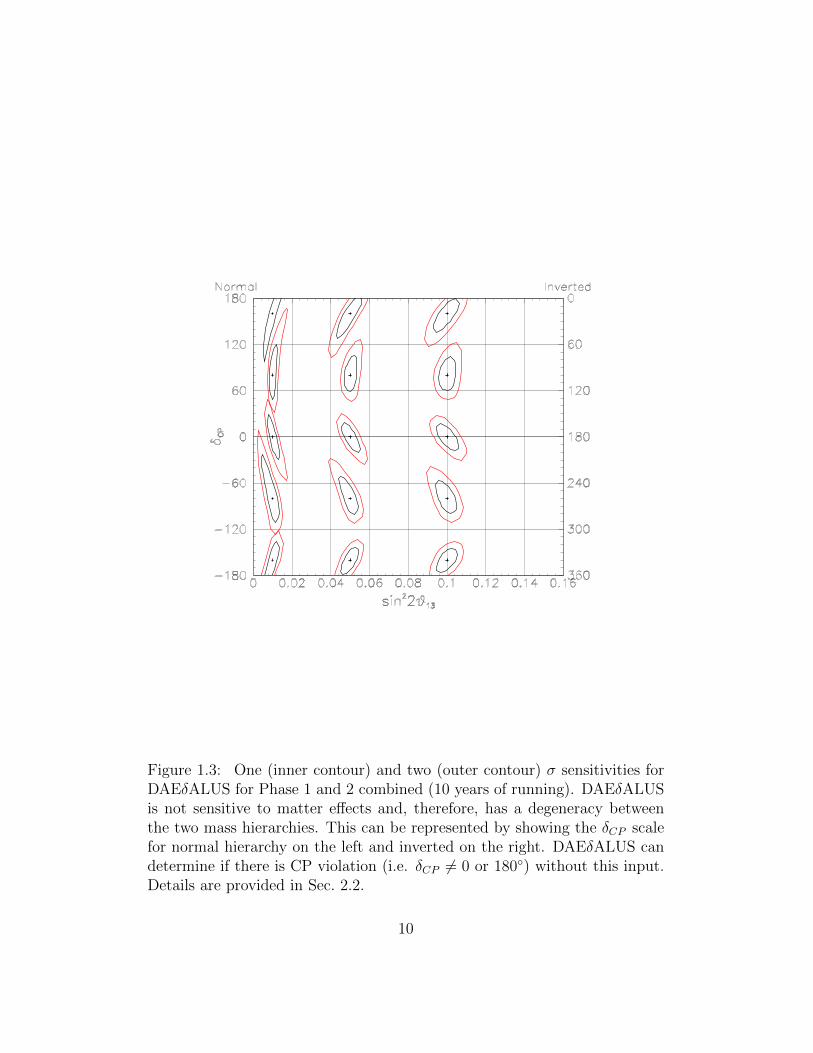
Figure 1.3: One (inner contour) and two (outer contour) σ sensitivities forDAEδALUS for Phase 1 and 2 combined (10 years of running). DAEδALUSis not sensitive to matter effects and, therefore, has a degeneracy betweenthe two mass hierarchies. This can be represented by showing the δCP scalefor normal hierarchy on the left and inverted on the right. DAEδALUS candetermine if there is CP violation (i.e. δCP 6= 0 or 180◦) without this input.Details are provided in Sec. 2.2.
10

Figure 1.4: The 3σ confidence level sensitivity for determining a non-zerovalue for θ13 as a function of sin2 2θ13 and δCP . Solid-with-dots: DAEδALUSphase 1+2 result; Dashed: LBNE proposed running (30 × 1020 POT in νmode and 30 × 1020 POT in ν mode); Solid (Dot-dashed): the combinedDAEδALUS plus LBNE ν-only result for 10 years (5 years). For the LBNEinput, which is affected by matter effects, we assume normal hierarchy. De-tails are provided in Sec. 2.3.
11

Figure 1.5: One (inner contour) and two (outer contour) σ sensitivitiesfor the DAEδALUS+LBNE ν—10 yr scenario. Normal mass hierarchy isassumed for LBNE. Details are provided in Sec. 2.3.
12

0.0
0.2
0.4
0.6
0.8
1.0
0.001 0.01 0.1sin2(2θ13)
Frac
tion
of δ
CP
Daedalus (10yrs)LBNE (5yrs/30e20+5yrs/30e20)Daedalus + LBNE nu-only (10 yrs/60e20)LBNE ProjectX (5yrs/100e20+5yrs/100e20)
Figure 1.6: Fraction of δCP space over which a measurement can be dif-ferentiated from 0 or 180◦ at 3σ. Red solid: Combined sensitivity for theDAEδALUS+LBNE ν—10 yr scenario. Dashed with ×: Project X scenariofor LBNE (5 years of running with 100× 1020 protons on target in neutrinomode followed by 5 years of running 100× 1020 protons on target in antineu-trino mode). Expectations for standard running for DAEδALUS (solid linewith dots) and LBNE dashed) are also shown. Normal mass hierarchy isassumed for LBNE. Details are provided in Sec. 2.3.
13

Chapter 2
The Physics Opportunities ofDAEδALUS
2.1 CP Violation and Neutrinos
The search for CP violation in the light-neutrino sector is a priority of theparticle-physics community [12, 13]. Interest has been sparked by modelswhich invokes GUT-scale Majorana neutrino partners which can decay, pro-ducing a matter-antimatter asymmetry in the early universe through themechanism of CP violation [14, 15, 16]. This process is called “leptogene-sis.” Observation of CP violation in the light neutrino sector would be astrong hint that this theory is correct. At the same time, one can argue thatthe (dis)similarities of mixing in the lepton and quark sectors provide cluesabout the theory at the highest energy scale, and information on the relativelevel of CP violation in the sectors can push this even further (Refs. [17, 18]provide examples).
DAEδALUS, a short-baseline νµ → νe experiment, approaches this high-priority search in a novel manner. In this section, we describe the theory ofCP violation in the neutrino sector, with emphasis on those aspects specificto the DAEδALUS design.
14
2.1.1 Introducing CP Violation into the Light Neu-trino Sector
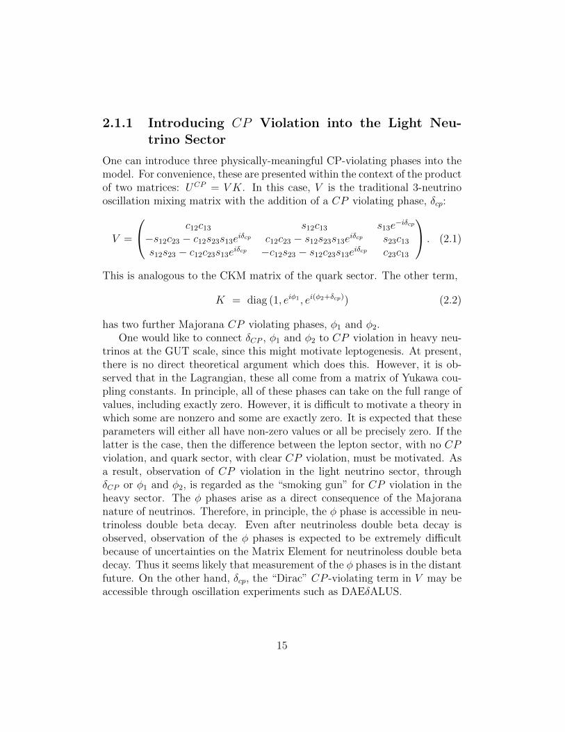
One can introduce three physically-meaningful CP-violating phases into themodel. For convenience, these are presented within the context of the productof two matrices: UCP = V K. In this case, V is the traditional 3-neutrinooscillation mixing matrix with the addition of a CP violating phase, δcp:
V =
c12c13 s12c13 s13e−iδcp
−s12c23 − c12s23s13eiδcp c12c23 − s12s23s13eiδcp s23c13s12s23 − c12c23s13eiδcp −c12s23 − s12c23s13eiδcp c23c13
. (2.1)
This is analogous to the CKM matrix of the quark sector. The other term,
K = diag (1, eiφ1 , ei(φ2+δcp)) (2.2)
has two further Majorana CP violating phases, φ1 and φ2.One would like to connect δCP , φ1 and φ2 to CP violation in heavy neu-
trinos at the GUT scale, since this might motivate leptogenesis. At present,there is no direct theoretical argument which does this. However, it is ob-served that in the Lagrangian, these all come from a matrix of Yukawa cou-pling constants. In principle, all of these phases can take on the full range ofvalues, including exactly zero. However, it is difficult to motivate a theory inwhich some are nonzero and some are exactly zero. It is expected that theseparameters will either all have non-zero values or all be precisely zero. If thelatter is the case, then the difference between the lepton sector, with no CPviolation, and quark sector, with clear CP violation, must be motivated. Asa result, observation of CP violation in the light neutrino sector, throughδCP or φ1 and φ2, is regarded as the “smoking gun” for CP violation in theheavy sector. The φ phases arise as a direct consequence of the Majorananature of neutrinos. Therefore, in principle, the φ phase is accessible in neu-trinoless double beta decay. Even after neutrinoless double beta decay isobserved, observation of the φ phases is expected to be extremely difficultbecause of uncertainties on the Matrix Element for neutrinoless double betadecay. Thus it seems likely that measurement of the φ phases is in the distantfuture. On the other hand, δcp, the “Dirac” CP -violating term in V may beaccessible through oscillation experiments such as DAEδALUS.
15

2.1.2 CP Violation in Neutrino Oscillations
The parameter δCP is accessible through the muon-to-electron neutrino flavoroscillation probability. For oscillations in a vacuum, this is given by [19]:
Pµ→e = sin2 θ23 sin2 2θ13 sin2 ∆31
∓ sin δ sin 2θ13 sin 2θ23 sin 2θ12 sin2 ∆31 sin ∆21
+ cos δ sin 2θ13 sin 2θ23 sin 2θ12 sin ∆31 cos ∆31 sin ∆21
+ cos2 θ23 sin2 2θ12 sin2 ∆21 (2.3)
where ∆ij = ∆m2ijL/4Eν . In the second term, the −(+) refers to neutrino
(antineutrino) running. Traditionally, searches for CP violation throughnon-zero δCP have relied on comparing neutrino and antineutrino oscillationprobabilities, exploiting this change of sign in order to isolate δCP . However,DAEδALUS will be a search only in antineutrino mode: νµ → νe, and so inour case, only the + sign applies. Sensitivity to CP violation comes aboutthrough the interference between ∆12 and ∆13 transitions, which has a dis-tinctive L dependence that we will exploit. Eq. 2.3 depends on many param-eters. However, most are well-known. In Table 2.1, we provide a summaryof the present level of knowledge of the parameters, as well as the improve-ment expected in the future, where “NIN” (No Improvement Needed) indi-cates that any future improvement does not impact the DAEδALUS analysis.Along with δCP , which is the focus of DAEδALUS, two other parameters, θ13and the sign of ∆m2
31, are unknown.With respect to θ13, global fits report a non-zero value at the ∼ 1σ level
[20, 21]. This parameter drives the amplitude for the CP violating terms inEq. 2.3 and therefore sets the level of technical difficulty for observing CPviolation. There is a clear road-map toward discovery and measurement ofθ13 within the present neutrino program [11] which dovetails well in timewith the DAEδALUS search. DAEδALUS data will provide some constrainton sin2 θ13; however, the external data remain important to the analysis.Because there is a dependence on both δCP and sin2 2θ13, the DAEδALUSsensitivity must be expressed in a δCP -sin2 2θ13 plane, as shown in Fig. 1.3.
The unknown sign of ∆m231, referred to as “the mass hierarchy,” will lead
to an inherent degeneracy in the DAEδALUS analysis. From Eq. 2.3, onecan see that for the DAEδALUS νµ → νe search, the probabilities for thecombination (δCP , sign(∆m2
31) = +1) and (180− δCP , sign(∆m231) = −1) are
equal. In the text below, we will refer to sign(∆m231) = +1 as the “normal
16

Parameter Present: Assumed Future:Value Uncert. Ref. Value Uncert. Ref.
(±) (±)∆m2
21 × 10−5eV2 7.65 0.23 [20] 7.65 NIN NIN∆m2
31 × 10−3eV2 2.40 0.12 [20] 2.40 0.02 [22]sin2(2θ12) 0.846 0.033 [20] 0.846 NIN NINsin2(2θ23) 1.00 0.02 [20] 1.00 0.005 [23]sin2(2θ13) 0.06 0.04 [21] 0.05 0.005 [24]
Table 2.1: Left: Present values and uncertainties for oscillation parameters,reported in the listed references. Right: Future expectations used in thisstudy, based on assumptions from the associated references. NIN means“No Improvement Needed” for the DAEδALUS analysis – the present valuesare sufficiently precise.
hierarchy” and sign(∆m231) = −1 as the “inverted hierarchy.” Given that the
degeneracy is perfect, we can express the DAEδALUS sensitivity for normaland inverted hierarchy on the same plot. In Fig. 1.3, the left vertical axisassumes the normal hierarchy and the right vertical axis assumes the invertedhierarchy.
2.1.3 The Mass Hierarchy and Matter Effects
External information will be required in order to break the mass hierarchydegeneracy in DAEδALUS. There are two sources of this information. First,the next generation neutrinoless double beta decay experiments, when com-bined with neutrino mass measurements from cosmology or direct searches,can, in principle, demonstrate the inverted mass hierarchy, if neutrinos areMajorana [25]. On the other hand, if no signal is seen, one does not knowwhether the hierarchy is normal or if neutrinos are not Majorana. A sec-ond approach is to use “matter effects” in muon-to-electron-neutrino, long-baseline, oscillation searches. These occur because neutrino and antineutrinobeams will have a different forward-scattering amplitude as the beam prop-agates through the earth. The result is an “effective CP violation” — adifference in the rate of neutrino versus antineutrino oscillations which arisesfrom some effect other than CP violation in the lepton-W coupling. Thesearise regardless of whether neutrinos are Majorana in nature or not.
17

Matter effects result in a modification of Eq. 2.3:
Pmat =
sin2 θ23 sin2 2θ13sin2 (∆31 ∓ aL)
(∆31 ∓ aL)2∆2
31
∓ sin δ sin 2θ13 sin 2θ23 sin 2θ12 sin ∆31sin (∆31 ∓ aL)
(∆31 ∓ aL)∆31
sin (aL)
(aL)∆21
+ cos δ sin 2θ13 sin 2θ23 sin 2θ12 cos ∆31sin (∆31 ∓ aL)
(∆31 ∓ aL)∆31
sin (aL)
(aL)∆21
+ cos2 θ23 sin2 2θ12sin2 (aL)
(aL)2∆2
21. (2.4)
In this equation, a = GFNe√2
and ∓ refers to neutrinos (antineutrinos). Thesame terms which are modified by the matter effects also will depend uponsign(∆m2
31). Because of this, the matter effects provide sensitivity to themass hierarchy. Matter effects only appear when L is large, because a ≈(3500 km)−1, for ρYe = 3.0 g/cm3, is small. Short-baseline experiments,such as DAEδALUS, suffer negligible matter effects, and this is even trueof moderate baseline experiments such as T2K [24], which is at 295 km.However the new generation of proposed long baseline beams, starting withNoνA [26], at 730 km, and moving on to longer baselines in Japan [27] andthe US [2], at > 1000 km, will be sensitive to matter effects.
Matter effects are interesting in their own right. However, if one seeks tostudy CP violation in the lepton-W coupling in the same experiment, theyhave to be measured and removed. This is challenging if sin2 2θ13 is small,as one can see from Eq. 2.4. Also, if the hierarchy is inverted, the neutrinooscillation probability is suppressed, substantially reducing the statistics forneutrino oscillations. The result is that the mass hierarchy may be difficultto determine using this method, unless sin2 2θ13 is large.
In summary, DAEδALUS will have negligible matter effects. As a result,our experiment has sensitivity to CP -violation without complications of anextra source of effective CP violation. This offers a more straight-forwardmethod of discovering and measuring δCP . However, it means that a degen-eracy with the mass hierarchy will remain until sign(∆m2
31) is measured insome other experiment.
18

2.1.4 Oscillation Probability Calculations
The code used for calculating the oscillation probabilities presented in thisEOI was written by Stephen Parke of Fermi National Accelerator Laboratory.The calculation uses the equations provided in Ref. [19]. The full formula,including matter effects, is used in all probability calculations presented inthis EOI.
The collaboration has also implemented the DAEδALUS neutrino fluxesin the GLoBES neutrino oscillation simulation program [28]. We have verifiedthat the probability calculations from the Parke code match the calculationsfrom GLoBES. In the near future, we plan to contact the GLoBES authorsin order to include these fluxes in the open-source GLoBES package.
2.2 DAEδALUS and CP Violation
The primary goal of DAEδALUS is to search for CP violation in a comple-mentary manner to the present plans [24, 2]. The present suite of experimentsis based on long-baseline “conventional” neutrino beams. These beams areproduced by impinging high-energy protons on a target, resulting in pionsand kaons which are sign-selected and focused by a magnet in the directionof a neutrino detector located ∼ 1000 km away. CP violation is explored bycomparing the rates of νµ → νe to νµ → νe These experiments are hamperedby a lack of antineutrino statistics and by poor signal-to-background ratio.These experiments have the added complication of matter effects.
Given the high priority placed on a convincing measurement of δCP ,should it be nonzero, we were motivated to develop a design which addressesthese issues. We propose to use pion decay-at-rest beams, which producemuon antineutrinos peaked at 50 MeV, at three locations at short baselineto a large detector. This design will provide a high-statistics data samplewhich explores CP violation through the L dependence of the interferenceterms of Eq. 2.3. The measurement is novel in that it is done with antineu-trinos exclusively, while all existing proposals rely most heavily on neutrinodata. The antineutrino flux uncertainties are different from the flux uncer-tainties of conventional beams and are well-controlled. Because of the lowbeam energy, the interaction systematics are also different from those of thepresent program. Varying L, while employing a single detector, is novelfor an appearance experiment (though it has been successfully employed at
19

KamLAND [29] and Super-K [30] for disappearance) and reduces systemat-ics. A two-phase program which allows an optimized measurement strategyis powerful and potentially cost-saving.
This chapter very briefly describes the design of the experiment. This isfollowed by an extended discussion of event types, backgrounds and system-atics in order to justify the sensitivity which is presented in Fig. 1.3. Moreinformation on design specifics and issues is then provided in the followingchapters.
2.2.1 Overview of the DAEδALUS Design
DAEδALUS searches for νµ → νe oscillations using neutrinos from threestopped-pion, decay-at-rest (DAR) beams, which interact in the 300 kton,Gd-doped water Cherenkov detector at DUSEL. This results in low system-atics for the beam and detector. The shape of the DAR flux with energy isknown to high precision and is common among the various distances, thusshape comparisons will have small uncertainties. The neutrino flux from thethree distances is accurately determined from the direct measurement of theπ+ production rate using neutrino-electron scattering events from the nearaccelerator. The interaction and detector systematic errors are low since allevents are detected in a single detector. The neutrino-electron cross sectionfor normalization and inverse-beta-decay cross section for the signal are well-known. The fiducial volume error on the IBD events is also small due to theextreme volume-to-surface-area ratio of the ultra-large detector.
The beams are to be produced by proton accelerators with kinetic energyin the 650 MeV to 1.5 GeV range. In this range, the ∆ resonance dominatesπ+ production and little energy is lost to the production of other particles,such as neutrons or π−s. As a result, in this energy range, for a given totalpower on target, the number of neutrino events produced by a DAR beam isflat as a function of proton energy; see Fig. 2.1.
Our proposal is to use low-cost cyclotrons, which are under developmentfor commercial use, to provide the proton beams. Development of high inten-sity cyclotrons which are ∼ 1 GeV is being driven by interest in acceleratordriven systems (ADS) for thorium reactors and active interrogation for home-land security. The work builds upon the recent development of cyclotronsfor medical uses. These cyclotrons are generally of two types: ∼ 30 MeV andhigh power for PET isotope production and ∼ 250 MeV and low power forcancer therapy. The evolution from medical machines to high powered, ∼ 1
20

“DeltaPlateau”
EProton (MeV)
Figure 2.1: νµ production (arbitrary units) as a function of proton energyfor 0.5, 1.0 and 1.5 MW on target
GeV machines does require further development, and there are none on themarket today. However, we have found three groups interested in developingand commercializing cyclotrons which will satisfy our needs over the nextfew years. Machine options are discussed in Chapter 3.1.
Neutrinos are produced through the decay chain
π+ → νµ µ+
↪→ νµe+νe, (2.5)
(2.6)
with a flux shown in Fig. 1.1. The shape of this energy distribution is definedby the weak interaction, but the overall normalization may vary betweenbeam stops. We describe how we normalize the accelerator sources usingevents in the detector in the discussion below. This beam is isotropic, so theorientation of the accelerator with respect to the detector does not affect thefluxes of these three flavors. On the other hand, νe is produced at the ∼ 10−4
level, as discussed below, from the chain of π− which decay in flight. Thisbackground can be significantly reduced by pointing the primary beam at120◦ or more with respect to the detector [31]. The νe/νe ratio also can besuppressed by designing the beamstops with a low-A target surrounded by a
21

1.5 kmAccelerator
8 kmAccelerators
20 kmAccelerators
100µs
100µs
100µs
100µs
100µs
100µs
400µs 400µs
400µs 400µs
100µs 100µs 100µs400µs 400µs
Beam Off Beam Off
Figure 2.2: The source accelerator for events is identified through timing.We propose to run each accelerator with a 20% DF. Beam-off time allowsmeasurement of non-beam-backgrounds. The timing structure presented hereis illustrative, and longer intervals are not an issue for the analysis.
high-A absorber [32, 33]. The oscillated neutrinos are detected through theinverse-beta-decay (IBD) interaction, νe+p→ e+ +n. This interaction has ahigh cross section at ∼ 50 MeV, but requires a detector with a high fractionof free protons. The large water Cherenkov detector at DUSEL, which isproposed to be 300 ktons, is ideal for this. Should DUSEL choose to installa large liquid-scintillator module, this could also be used, though we do notpresent details here. The large liquid-argon detectors cannot be used for thisanalysis because there are no free proton targets.
In order to differentiate the signal IBD interactions from νe interactions,Gd-doping of the detector is required [3]. Fortunately, interest in studyingsupernova relic neutrinos and in using the large detector for non-proliferationstudies has pushed forward techniques for Gd-doping water [4, 5, 6]. Gd-doping is within the scope of the S4 development. We discuss the issue ofGd-doping further in Chapter 3.2.
The accelerators will be positioned at 1.5, 8, and 20 km from the largewater Cherenkov detector. The 1.5-km, “near accelerator” position is 4850feet from the detector — that is, the accelerator remains above ground. Thecomplexity of running the accelerators is sufficiently high to make above-ground running desirable. This accelerator will be on the DUSEL site. The1.5-km accelerator allows measurement of the beam-on backgrounds and thenormalization. The 8-km site is at an oscillation wavelength of about π/4 at50 MeV and the 20-km site is at oscillation max for this energy. These two
22

accelerators are referred to as the “signal accelerators,” below. The locationfor these accelerators are off the DUSEL site and will need to be negotiated.We have in mind other mining sites which are no longer in use, but whichhave access roads and power.
We plan to run each site for 20% of the time; see Fig. 2.2. This allowsus to use the time-stamp to identify which events come from each accelera-tor site. IBD events do not have a strong angular dependence [34], and soevent-pointing cannot be used to connect events to a given accelerator. Thisalso allows time for beam-off running, in order to measure non-beam-relatedbackgrounds. Our initial proposal is to run each accelerator for 100 µs, with400 µs beam-off. However, other timing patterns can be considered, up tointervals of minutes and even hours. During the interval that a given accel-erator is on, it is run continuously (“cw”). We propose a phased runningplan over 10 years. In Phase 1, we begin with 1 MW, 2 MW and 3 MW atthe respective 1.5-km, 8-km, and 20-km sites. The purpose of this run is todiscover CP -violation at the 3σ level, which is a 5-year run. At that point,more accelerators can be added in the proportion which is most advantageousto measuring the signal. Fig 1.3 is for a 2-phase run where the second 5-yearperiod has 1, 2 and 7 MW at the three respective sites.
2.2.2 Events in the Detector
2.2.2.1 Neutrino Interactions of Interest to the Analysis
There are three important event types in this analysis: neutrino-electronscatters, νe-oxygen scatters, and IBD Events. The event rates for the 10year run are shown in Table 2.2. The energy ranges for the analysis arelisted below. The lower energy bound for the event samples is chosen tomaintain a region of high signal-to-background. The upper bound is justabove the 52.8 MeV endpoint of the neutrino spectra.
Neutrino-electron scatters During the 10-year run, 21.5k events will becollected from the near accelerator. Because the cross section for these eventsis known to better than 1% [35], these events can be used to obtain a precisemeasure of the near-accelerator flux normalization. The neutrino-electronanalysis uses events in the visible energy range of 10 to 55 MeV. Neutrino-electron scatters can be separated from νe-oxygen scatters by angular cuts
23

Event Type 1.5 km 8 km 20 kmIBD Oscillation Events (Evis > 20 MeV)δCP = 00, Normal Hierarchy 763 1270 1215
” , Inverted Hierarchy 452 820 1179δCP = 900, Normal Hierarchy 628 1220 1625
” , Inverted Hierarchy 628 1220 1642δCP = 1800, Normal Hierarchy 452 818 1169
” , Inverted Hierarchy 764 1272 1225δCP = 2700, Normal Hierarchy 588 870 756
” , Inverted Hierarchy 588 870 766IBD from Intrinsic νe (Evis > 20 MeV) 600 42 17IBD Non-Beam (Evis > 20 MeV)
atmospheric νµp “invisible muons” 270 270 270atmospheric IBD 55 55 55
diffuse SN neutrinos 23 23 23ν−e Elastic (Evis > 10 MeV) 21570 1516 605νe−oxygen (Evis > 20 MeV) 101218 7116 2840
Table 2.2: Event samples for the combined two-phase run for sin2 2θ13 = 0.05and parameters from Table 2.1 (future).
24

0
200
400
600
800
1000
1200
1400
1600
1800
0 45 90 135 180 225 270 315 360
0CP
Nue
bar
Even
ts
1.5km - normal1.5km - inverted
0
200
400
600
800
1000
1200
1400
1600
1800
0 45 90 135 180 225 270 315 360
0CP
Nue
bar
Even
ts
8km - normal8km - inverted
0
200
400
600
800
1000
1200
1400
1600
1800
0 45 90 135 180 225 270 315 360
CP
Nue
bar
Even
ts
20km - normal20km - inverted
Bkgnd
Bkgnd Bkgnd
δCP δCP δCP
Figure 2.3: The oscillation event distribution as a function of δCP from eachaccelerator for the 10 year run, assuming sin2 2θ13 = 0.05. The green lineindicates the level of background for each data set.
[36, 37]. We estimate the reconstruction efficiency of these events as εrecon =75% based on Ref. [36]
νe-oxygen scatters During the 10-year run a large sample of these eventsare collected from all three accelerators. The cross section is suppressedcompared to the IBD cross section, because the target nucleons are bound[38, 39]. The cross section is not well-known, and we use a parameterizationfrom Ref. [38], which gives the smaller predicted data set. (We note that anoutcome of DAEδALUS will be a precise measurement of this cross sectionfrom the near accelerator data set, as discussed in Sec. 2.4). The samplefrom the 20-km accelerator is on the order of 2800 events, implying a 2%statistical error, for visible energy between 20 and 55 MeV. Comparing therates between the three accelerators, adjusting for the 1/r2 dependence of theflux, allows determination of the normalization across the sites. We estimatethe reconstruction efficiency of these events as εrecon = 75%.
IBD Events These are the signal events for νµ → νe oscillations. The num-ber of events, therefore, depends upon the oscillation parameters. Fig. 2.3
25

Blue: Intrinsic νe bkgndRed: Beam off bkgndBlack: δCP= 00
Violet: δCP= 450
Green: δCP=-450
MeV
MeV MeV
Figure 2.4: The event energy distributions for signal and background atsin2 2θ13 = 0.04. Black, green and violet histograms show signals for δcp = 0,45◦ and -45◦. The blue histogram shows the intrinsic νe beam-on background.The red histogram shows the beam-off backgrounds. Top row: the nearaccelerator events. Bottom row: events in the signal accelerators
shows how the event rate from the three accelerators varies for the 10 yearrun, as a function of δCP , assuming sin2 2θ13 = 0.05. One can see thatthe design leads to roughly equal signal samples from the 8-km and 20-kmaccelerator. One can also see that the 1.5-km accelerator will have signalevents, and this must be included in the fits. Events in the energy rangeof 20 to 55 MeV will be used in the analysis, and the distribution of eventsis strongly peaked at about 50 MeV; see Fig. 2.4. As a result, DAEδALUSmay be thought of as a narrow-band beam experiment. In this energy range,three types of interactions must be considered. First is the IBD signal, withan estimated reconstruction efficiency of εrecon = 67%, based on studies forSuper-K [4].
26

0
0.2
0.4
0.6
0.8
1
1.2
1.4
1.6
-1 -0.8 -0.6 -0.4 -0.2 0 0.2 0.4 0.6 0.8 1
cosθ
ν e-O
xyge
n R
ate
Figure 2.5: Rate of νe-oxygen events as a function of scattered electron angle.The shaded region, with cos θ > 0.90, is the region which the neutrino-electron scatters will populate.
2.2.2.2 Background Events
The total background from each accelerator is indicated by the green lineson Fig. 2.3. The energy distribution of the backgrounds compared to theexpected events for sin2 2θ13 = 0.04 and three values of δCP are shown inFig. 2.4. One can see that the near accelerator (left in Fig. 2.3 and topin Fig. 2.4) provides a high-statistics sample for the beam-on backgroundmeasurement. Because the isotropic beam produces backgrounds that fallas 1/r2, the signal accelerators have very little beam-on background. In thesignal accelerators, the beam-off background dominates.
The beam-on backgrounds are dominated almost entirely by intrinsic νeevents in the beam. In principle, correlated beam-on backgrounds may beproduced by νe charged current (CC) scatters in which a neutron is emitted.This is of special concern for interactions with 17O and 18O, which havenatural abundances of 0.04% and 0.20%, respectively. We find that the rateof neutron production is negligible from excited 16F [40], 17F [41], and 18F[42]. However, excited 18F will decay to nitrogen plus an α. Data from the
27

(α, n) interaction on oxygen indicate about 1 × 10⁻⁸ neutrinos per 3 MeVα [43]. Hence, we expect this background to be negligible. The accidentalbackgrounds arise from the νe in the beam that are followed by a neutron-likeevent. This background is estimated to be very small using the measurementsfrom the Super-K Gd-doping study [4]. As a result, in Figs. 2.3 and 2.4 weonly show the intrinsic νe background, as the blue histogram. However, inthe final data analysis all background sources are included.
Beam-off backgrounds arise from atmospheric νµp scatters with muonsbelow Cherenkov threshold that stop and decay (“invisible muons”), atmo-spheric νe IBD events, and supernova relic neutrinos. These are all examplesof correlated backgrounds. The rates of these correlated backgrounds arescaled from analyses for the GADZOOKS experiment [3]. As, this study wasdone for the latitude of Super-K, not for DUSEL, in the future the level ofthis background will need to be adjusted; however, this study is sufficient forillustrative purpose in this EOI. The interaction rates of the beam-off back-grounds will be well-measured during the 40% beam-off running fraction.Thus the dominant beam-off error is the statistical error from the bin-by-binbackground subtraction.
2.2.3 Systematic Errors Before Constraints
In the analysis, initial systematic uncertainties are assigned to quantities,which are then further constrained by fits to the DAEδALUS data set.Tab 2.3 provides the inputs for the systematics in the fit. The resultingfinal systematic error, after constraints, is at the level of 2%.
Because the flux chain begins with π+ production, this systematic erroris common to all types of events in the normalization and signal samples.This uncertainty is not well known, but becomes highly constrained whenwe use the neutrino-electron sample to set the overall normalization. Thusthe analysis is insensitive to the level we assume as an input systematicuncertainty, which we take to be 10% here.
For the neutrino-electron sample, the largest systematic uncertainty comesfrom knowledge of the energy scale at Evis = 10 MeV, the position of thecut in this analysis. This estimate comes from Super-K [44] and leads toa 1% error on the DAR flux normalization. However, we think that this isan overestimate. As we discuss in Sec. 4.1, the energy dependence of theneutrino-electron sample is very well predicted. Demanding that the ratio
28

Systematics on the NormalizationOn all events Fractional Uncertaintyπ+ production 0.100Neutrino-electron scattering events Fractional Uncertainty2.1% energy scale uncertainty 0.010Cross section error from NuTeV sin2 θW 0.005Background subtraction systematics 0.000νe-oxygen scattering Fractional UncertaintyCross section 0.100
Systematics on the SignalOscillation IBD events Fractional UncertaintyEfficiency of neutron detection 0.005Fiducial volume 0.000
Systematics on the BackgroundsIntrinsic νe IBD Events Fractional Uncertaintyπ− production 0.100π− decay-in-flight 0.100µ− decay-in-flight 0.050
Beam-off subtraction Fractional UncertaintyStatistical error for Phase 1 period 0.054Statistical error for Phase 2 period 0.038
Table 2.3: Systematic errors which are inputs to the fits. The systematicsare then further constrained by the event samples in the fit.
29

sin22θ13/δCP –180 –90 0 90 1350.01 52.5 47.2 29.0 38.8 48.50.05 21.6 21.9 19.5 25.6 30.40.09 18.3 19.9 17.6 23.8 26.30.01 51.3 45.5 26.9 36.7 46.90.05 19.9 21.2 18.2 24.2 29.60.09 16.8 19.2 16.5 22.6 25.3
Table 2.4: The 1σ measurement uncertainty on δCP for various values ofsin2 θ13 for the combined two-phase data. Top: Systematic and statisticalerrors. Bottom: Statistical error only.
of measured to predicted energy distribution be flat should allow for energycalibration to better than 1%. The next largest error is due to the erroron the cross section normalization from our knowledge of sin2 θW . The LEPand SLAC results provide a precision measurement of sin2 θW which is in 3σdisagreement with the NuTeV deep inelastic neutrino scattering results (fordiscussion see Ref. [45]). Taking an agnostic viewpoint, we assign a system-atic error which covers this disagreement, leading to the cross section errorin Table 2.3.
The analysis relies on obtaining a pure sample of neutrino-electron scat-ters. The νe events on oxygen and IBD events with a missing neutron rep-resent potential sources of background. However, these can be separatedfrom the neutrino-electron sample since the angular distribution of neutrino-electron events is very forward-peaked, while νe-oxygen scatters have a broaddistribution [37], as shown in Fig. 2.5. Only 0.8% of the νe−oxygen eventshave cos θ > 0.90 (i.e., θ < 25◦), as shown by the shaded region, giving a lessthan 4% background to the IBD sample. These backgrounds can be mea-sured in the cos θ < 0.90 region and extrapolated into the neutrino-electronsignal region, allowing them to be subtracted with negligible error, as weexplicitly list in Table 2.3.
The largest input uncertainty on the IBD signal events arises from neutron-tagging and is taken to be 0.005. We also considered a fiducial volume error.Because the volume-to-surface area is so high in these large detectors, wefind this error to be negligible.
The largest systematics associated with the intrinsic νe background arerelated to the π− production and decay chain. However the final analysis is
30

-180
-120
-60
0
60
120
180
0.0001 0.001 0.01 0.1
sin2(2θ13)
δ CP
3 sigma Phase I5 sigma3 sigma Phase II5 sigma
Figure 2.6: Phase-1 and Combined-phase sensitivity to θ13 6= 0 at 3σ and 5σ.
insensitive to these effects for two reasons. First, the near accelerator providesa high precision in-situ measure of the background. Second, because of the1/r2 dependence of this flux in the signal accelerators, the rate is small (seeblue histograms in Fig. 2.4, bottom).
The beam-off rates are measured rather than predicted. Therefore thesystematic error associated with this source comes from the statistical erroron the background subtraction.
2.2.4 Oscillation Sensitivities
Sensitivity estimates were made using a method similar to that describedin Ref. [24]. Data are generated according to the experimental expectationswith assumed underlying parameters. For a given set of new parameters,a standard χ2 value is found by comparing the prediction with these pa-rameters to the originally generated data. The difference between this χ2
value and the one calculated with the original parameters is the χ2 value.
31

0
5
10
15
20
25
30
-180 -135 -90 -45 0 45 90 135 180
δCP (degrees)
1 σ u
ncer
tain
ty o
n δ C
P (d
egre
es)
1.1% 0.5% (Syst. error: ES, IBD)2.5% 0.5%1.1% 2.5%2.5% 2.5%
Figure 2.7: The DAEδALUS result is insensitive to the input systematicerrors. In this study, we vary the magnitude of the input systematic uncer-tainties (these are the systematic uncertainties prior to the fit). For clarity,we consider only two of the errors ES and IBD (see text for details).
Systematic uncertainties are constrained by pull-term contributions of theform (ki − 1)2 /σ2
i , where σ2i are the uncertainties given in Table 2.1, for the
oscillation parameters and Table 2.3, for the experimental expectations. Theχ2 minimization is performed using the MINUIT program [46].
The DAEδALUS sensitivity is shown in Fig. 1.3. Information on thesensitivity is also tabulated in Table 2.4 (top), while Table 2.4 (bottom)tabulates the sensitivity considering only the statistical uncertainty.Thus,one can see that the DAEδALUS measurement is statistics-limited. Anotherway to present the DAEδALUS sensitivity is to consider the sensitivity forobserving a non-zero value for θ13 at the 3 and 5σ confidence level (CL)for Phase-1 (5-year) running and Phase-1+2 (10-year) running. This result
32
10
15
20
25
30
35
-180 -120 -60 0 60 120 180δcp
1 σ δ
cp U
ncer
tain
ty300kt Daedalus200kt300kt LBNE200kt
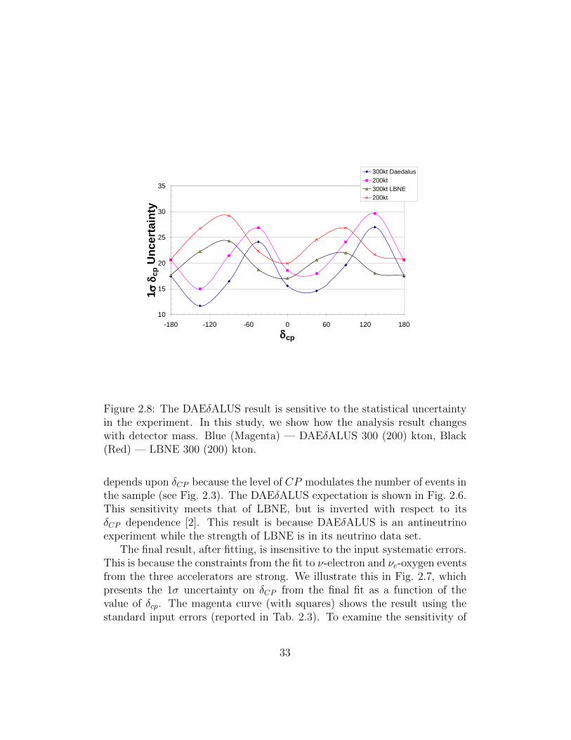
Figure 2.8: The DAEδALUS result is sensitive to the statistical uncertaintyin the experiment. In this study, we show how the analysis result changeswith detector mass. Blue (Magenta) — DAEδALUS 300 (200) kton, Black(Red) — LBNE 300 (200) kton.
depends upon δCP because the level of CP modulates the number of events inthe sample (see Fig. 2.3). The DAEδALUS expectation is shown in Fig. 2.6.This sensitivity meets that of LBNE, but is inverted with respect to itsδCP dependence [2]. This result is because DAEδALUS is an antineutrinoexperiment while the strength of LBNE is in its neutrino data set.
The final result, after fitting, is insensitive to the input systematic errors.This is because the constraints from the fit to ν-electron and νe-oxygen eventsfrom the three accelerators are strong. We illustrate this in Fig. 2.7, whichpresents the 1σ uncertainty on δCP from the final fit as a function of thevalue of δcp. The magenta curve (with squares) shows the result using thestandard input errors (reported in Tab. 2.3). To examine the sensitivity of
33

Figure 2.9: Expected events, as a function of energy in GeV, for the LBNEexperiment with a 300 kton water Cherenkov detector at 1300 km forν (5 yr) + ν (5 yr) running (see text for details). Black points — rate withstatistical error for sin2 2θ13 = 0.04, δCP = 0◦, and a normal hierarchy. Red— total background. Blue — intrinsic electron-flavor neutrino background.Left: νµ → νe running; Right: νµ → νe running.
the result to the magnitude of each input uncertainty, we arbitrarily increaseeach systematic error, in turn. For example, the effect of increasing theelastic scattering (ES) rate error from 1.1% to 2.5% is indicated in Fig. 2.7by the green line (with solid triangles). In fact, the new fit result, is so similarto the original fit (magenta line) that it is difficult to see on the plot. Thisis because the data strongly constrains the fit, so that the input systematicerror is not very important. As a second example, we return the ES errorback to its original value of 1.1% and increase the error on IBD event ratefrom 0.5% to 2.5%. The resulting new fit, indicated by the red line (withopen triangles), is also in excellent agreement with the original (magentaline) result. In order to see a small but clear effect in Fig. 2.7, one mustsubstantially increase both the ES and the IBD errors to 2.5%. This slightlyweakens the constraint from the data and the result is the brown curve (withclosed dots).
In contrast to the case of the systematic error, the DAEδALUS result isvery sensitive to the statistical errors in the experiment. In order to illustratethis sensitivity, Fig. 2.8 compares the DAEδALUS 1σ errors in δCP for the300 kton detector to a 200-kton detector. Even at 200 ktons, DAEδALUS
34

maintains > 3σ capability across a wide range of values of δCP . For com-parison, LBNE is less affected by a loss of statistics, because it is limited bysystematics. However, the > 3σ coverage at 200 ktons is less.
2.3 A Joint Analysis With the Fermilab Beam
The DAEδALUS high-statistics antineutrino data can be combined withLBNE neutrino-only running data to give a sensitivity for observing andmeasuring θ13 and δCP which far exceeds either experiment alone, as wellas the Project X expectation [8], and approaches that of the most sensitivesuperbeam facilities [10]. In this section, we describe the presently plannedLBNE sensitivity, which is based on equal neutrino and antineutrino running.For simplicity, we use the normal hierarchy as our example. We then explainwhat is gained by running LBNE in neutrino-only mode simultaneously withDAEδALUS. The results presented here are in agreement with Ref. [9], oncedifferences in the proposed design are taken into account.
2.3.1 LBNE Current Plans: ν (5 yr) + ν (5 yr) Running
The current plans for the long baseline neutrino experiment from Fermilab toDUSEL (LBNE) are as follows. LBNE proposes to use a wide band neutrinobeam, in the range of about 300 MeV to about 10 GeV [47]. This allows theLBNE beam, which is produced at a distance of 1300 km from the detectorsat DUSEL, to potentially observe both the oscillation maximum at about 3GeV and the second maximum near 0.9 GeV. To be specific, the LBNE fluxfiles used in this discussion are:
• dusel120e250i002dr280dz1300km flux.txt (neutrino flux)
• dusel120e250ni002dr280dz1300km flux.txt (antineutrino flux)
This is a 120-GeV, proton-on-target, on-axis, NuMI-like beam with a 280-mdecay, designed to reduce the high-energy tail above the first oscillation maxi-mum. This optimization is important because high-energy neutrinos producesingle and multiple neutral-current π0 mesons, which decay to produce elec-tromagnetic showers that are the primary misidentification background in abeam of this type.
We refer to the standard LBNE run as “ν (5 yr)+ν (5 yr).” This is definedto be 3×10²¹ POT in neutrino mode and 3×10²¹ POT in antineutrino mode.
35

-180
-120
-60
0
60
120
180
0.001 0.01 0.1
sin2(2θ13)
δ CP
3 sigma5 sigma
LBNE 5yr ν + 5yr⎯ν
Figure 2.10: The 3σ and 5σ confidence-level exclusion limits for determininga non-zero value for θ13 as a function of sin2 2θ13 and δCP , normal hierarchy,assuming ν (5 yr) + ν (5 yr), with the efficiency and uncertainties given inthe text.
Figure 2.11: Estimates of the uncertainty for a correlated measurement ofsin2 2θ13 and δCP at 1σ and 2σ, normal hierarchy, assuming ν (5 yr)+ν (5 yr).The efficiency and uncertainties are given in the text. Sensitivity is for theoptimized 120-GeV beam, discussed in the text.
36
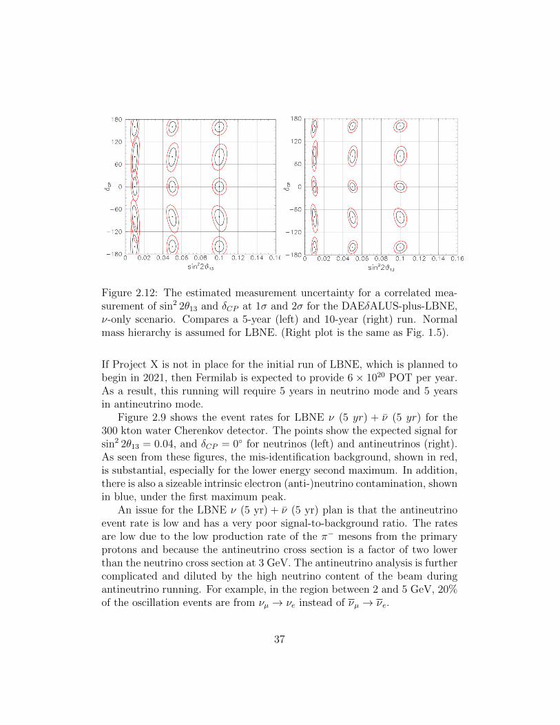
Figure 2.12: The estimated measurement uncertainty for a correlated mea-surement of sin2 2θ13 and δCP at 1σ and 2σ for the DAEδALUS-plus-LBNE,ν-only scenario. Compares a 5-year (left) and 10-year (right) run. Normalmass hierarchy is assumed for LBNE. (Right plot is the same as Fig. 1.5).
If Project X is not in place for the initial run of LBNE, which is planned tobegin in 2021, then Fermilab is expected to provide 6× 10²⁰ POT per year.As a result, this running will require 5 years in neutrino mode and 5 yearsin antineutrino mode.
Figure 2.9 shows the event rates for LBNE ν (5 yr) + ν (5 yr) for the300 kton water Cherenkov detector. The points show the expected signal forsin2 2θ13 = 0.04, and δCP = 0◦ for neutrinos (left) and antineutrinos (right).As seen from these figures, the mis-identification background, shown in red,is substantial, especially for the lower energy second maximum. In addition,there is also a sizeable intrinsic electron (anti-)neutrino contamination, shownin blue, under the first maximum peak.
An issue for the LBNE ν (5 yr) + ν (5 yr) plan is that the antineutrinoevent rate is low and has a very poor signal-to-background ratio. The ratesare low due to the low production rate of the π− mesons from the primaryprotons and because the antineutrino cross section is a factor of two lowerthan the neutrino cross section at 3 GeV. The antineutrino analysis is furthercomplicated and diluted by the high neutrino content of the beam duringantineutrino running. For example, in the region between 2 and 5 GeV, 20%of the oscillation events are from νµ → νe instead of νµ → νe.
37

In order to estimate the sensitivity for measuring θ13 and δCP for theν (5 yr) + ν (5 yr) scenario, we assume a 15% reconstruction efficiency andsystematic uncertainties of 1% for the neutrino/antineutrino flux, 10% forthe background, and 5% for the density along the flight path. With theseassumptions, the θ13 observation sensitivity is given in Fig. 2.10. The cor-related measurement precision for θ13 and δCP is shown in Fig. 2.11. Thesesensitivities can be compared to those of DAEδALUS shown in Figs. 2.6 and1.3. This leads to the conclusion that the two experiments, DAEδALUS andLBNE, are comparable in sensitivity and complementary in their regions ofbest precision.
2.3.2 DAEδALUS+LBNE (ν Only)
The complementarity of the two experiments suggests that a combination ofthe two should give improved sensitivity and precision. In fact, combining theDAEδALUS antineutrino data with an LBNE, neutrino-only data set givesa significantly improved oscillation sensitivity and measurement capability.The high-statistics, low-background DAEδALUS antineutrino data sampletakes the place of the limited LBNE antineutrino sample. In addition, theDAEδALUS samples bring in a sample with no matter effects and multipledistances that exploit the on and off-maximum terms in Eq. 2.4. The LBNEdata are sensitive to mass hierarchy through matter effects, and for the studybelow, we assume a normal hierarchy.
LBNE and DAEδALUS can take data simultaneously because the twodata sets are in well-defined energy ranges that do not overlap. Two scenariosare considered:
• DAEδALUS+LBNE ν—5 yr: A five-year run of both experiments,combining DAEδALUS Phase 1 with a 30 × 1020 POT ν−only LBNEdata set.
• DAEδALUS+LBNE ν—10 yr: A ten-year run of both experiments,with the Phase 1 + 2 DAEδALUS sample combined with a 60 × 1020
POT ν-only LBNE data sample.
The 1σ measurement uncertainties on δCP for various scenarios are givenin Table 2.5 for an assumed value of sin2 2θ13 = 0.05. As seen from thetable, the DAEδALUS+LBNEν—5-yr scenario does better that either theDAEδALUS Phase 1+2 or LBNE ν (5 yr) + ν (5 yr) measurements. The
38
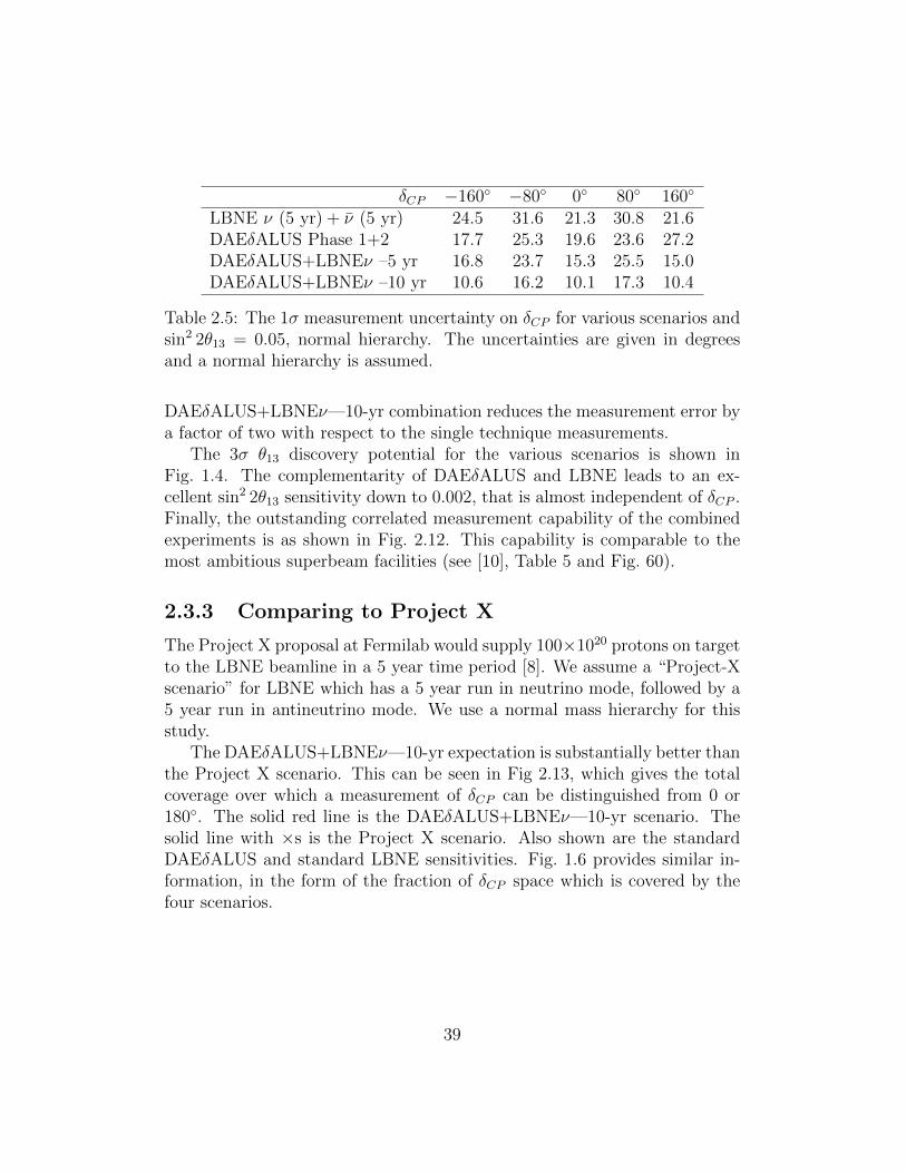
δCP −160◦ −80◦ 0◦ 80◦ 160◦
LBNE ν (5 yr) + ν (5 yr) 24.5 31.6 21.3 30.8 21.6DAEδALUS Phase 1+2 17.7 25.3 19.6 23.6 27.2DAEδALUS+LBNEν –5 yr 16.8 23.7 15.3 25.5 15.0DAEδALUS+LBNEν –10 yr 10.6 16.2 10.1 17.3 10.4
Table 2.5: The 1σ measurement uncertainty on δCP for various scenarios andsin2 2θ13 = 0.05, normal hierarchy. The uncertainties are given in degreesand a normal hierarchy is assumed.
DAEδALUS+LBNEν—10-yr combination reduces the measurement error bya factor of two with respect to the single technique measurements.
The 3σ θ13 discovery potential for the various scenarios is shown inFig. 1.4. The complementarity of DAEδALUS and LBNE leads to an ex-cellent sin2 2θ13 sensitivity down to 0.002, that is almost independent of δCP .Finally, the outstanding correlated measurement capability of the combinedexperiments is as shown in Fig. 2.12. This capability is comparable to themost ambitious superbeam facilities (see [10], Table 5 and Fig. 60).
2.3.3 Comparing to Project X
The Project X proposal at Fermilab would supply 100×1020 protons on targetto the LBNE beamline in a 5 year time period [8]. We assume a “Project-Xscenario” for LBNE which has a 5 year run in neutrino mode, followed by a5 year run in antineutrino mode. We use a normal mass hierarchy for thisstudy.
The DAEδALUS+LBNEν—10-yr expectation is substantially better thanthe Project X scenario. This can be seen in Fig 2.13, which gives the totalcoverage over which a measurement of δCP can be distinguished from 0 or180◦. The solid red line is the DAEδALUS+LBNEν—10-yr scenario. Thesolid line with ×s is the Project X scenario. Also shown are the standardDAEδALUS and standard LBNE sensitivities. Fig. 1.6 provides similar in-formation, in the form of the fraction of δCP space which is covered by thefour scenarios.
39

-180
-120
-60
0
60
120
180
0.001 0.01 0.1
sin2(2θ13)
δ CP
Daedalus (10yrs)LBNE (5yrs+5yrs)Daedalus+LBNE nu-only (10yrs)LBNE ProjectX (5yrs+5yrs)
Figure 2.13: The region in δCP and sin2 2θ13 space over which a measurementcan be differentiated from 0 or 180◦ at 3σ. Red solid: DAEδALUS+LBNEν—10 yr scenario, Dashed with ×: Project X scenario. Expectations forstandard running for DAEδALUS (solid line with dots) and LBNE (dashed)are also shown. Normal mass hierarchy is assumed for LBNE.
40

2.4 Physics with a Near Accelerator
The DAEδALUS near-accelerator will provide a high intensity source ofdecay-at-rest neutrinos in the 0-50 MeV energy range. Because of the in-tensity of the neutrino source, many additional physics topics besides thesearch for CP violation in the lepton sector become available. There are twobasic experimental situations possible: physics with the gigantic Gd-dopedwater Cherenkov detector that will be used for the CP violation measure-ment and physics that could be done with a dedicated detector on the 300foot level.
We briefly consider several physics topics accessible with the DAEδALUSnear accelerator flux. For each topic, we discuss briefly the physics issue andin some cases consider briefly the detector requirements. This is not meantto be a rigorous study but rather a sampling of the breadth of topics madeavailable by the intense DAEδALUS flux.
2.4.1 Coherent neutrino-nucleus scattering
Although the process has never been observed before, coherent neutrino-nucleus elastic scattering has the highest theoretical cross section in thisenergy range by about an order of magnitude. The non-observation is aresult of the low momentum transfer characteristic of this type of interaction.Typical nuclear recoil energies for this interaction fall in the∼0-100 keV rangefor medium-A nuclei.
Neutrino-nucleus coherent scattering is an unobserved Standard Modelprocess and as such, is interesting to pursue. Furthermore, any measureddeviation from the well-predicted Standard Model expectation could be asign of new physics. Neutrino-nucleus coherent scattering is also relevant forsupernova-burst neutrino detection in terms of oscillation physics and super-nova dynamics and evolution. Approximately ten neutrino-nucleus coherentevents on argon in a ten second window per ton for a galactic core-collapsesupernova at ten kiloparsecs are expected [48]. These neutral-current, flavor-blind, events could provide much-needed information about the νµ/νµ andντ/ντ supernova flux that is out of reach for conventional neutral-current-blind (at low energy) neutrino detectors.
A dedicated coherent neutrino-nucleus scattering detector will be requiredin order to make precision measurements of this process. A noble liquiddetector is envisioned at a distance of 10-50 m from the DAEδALUS near-
41

accelerator neutrino source. Assuming 4×10²²/flavor/year, a nuclear recoilenergy window from 20-120 keV (30-160 keV), a 1000 (857) kg LAr (LNe)target, and a baseline of 30 m, there will be about 9050 (3700) neutrino-nucleus coherent events/year in the detector. These event rates have beenfound scaling from the CLEAR proposal [49].
As for direct dark matter searches, cosmic-ray and intrinsic steady-statebackgrounds are a significant worry for a coherent neutrino-nucleus mea-surement. A dedicated coherent detector will enjoy the advantage of a beamwindow for background estimation and rejection and employ standard WIMPdetector background mitigation techniques. The DAEδALUS accelerator cy-cle allows a study of the steady state rate and reduction of the backgroundby 80% simply by the duty factor. The detector design and undergroundlocation can further improve background rejection.
2.4.1.1 Measurement of sin2 θW
Measuring the absolute cross section of neutrino-nucleus coherent scatteringcan provide sensitivity to the weak mixing angle. A cross section measure-ment with ∼10% uncertainty gives a sin2 θW uncertainty at a typical Q valueof 0.04 GeV/c of ∼5% [50]. Although a first generation experiment maynot be competitive with precision atomic parity violation and e-e scatter-ing experiments, it is worth noting that there are no other neutrino-basedmeasurements near Q∼0.04 GeV/c. Furthermore, the only neutrino-basedsin2 θW measurement (NuTeV) found a value 3σ away from the StandardModel prediction [51]. As for the weak mixing angle, planned and existingprecision measurements are not sensitive to new physics specific to neutrino-nucleus(on) interactions. An absolute cross section measurement consistentwith the Standard Model prediction with ∼10% uncertainty would providenon-standard neutrino interaction limits more sensitive than current limitsby more than an order of magnitude [50].
2.4.1.2 Non-standard interactions
As mentioned previously, coherent neutrino-nucleus scattering can be usedto search for new physics in the neutrino sector[52]. One can add to thestandard model Lagrangian an extra term of the form[53]:
− LeffNSI = εfPαβ 2√
2GF (ναγρLνβ)(fγρPf), (2.7)
42

where f is a first generation SM fermion: e, u or d, and P = L or R. Suchnon-standard interaction (NSI) terms can naturally appear when adding neu-trino mass into the standard model[54] or from super-symmetry [52]. Thus adiverse range of new physics can be included through the effective parameterεfPαβ and constrain using neutrino scattering data.
.
2.4.1.3 Additional processes
There are additional motivations for new measurements. For example, thenuclear neutron form factor can be linked to neutron star radii, and onemight measure this through neutrino-nucleus coherent scattering [55]. Alsocoherent scattering is a process that occurs during stellar collapse and precisemeasurements would be useful input to models.
Electron capture on nuclei occurs during stellar collapse, and measure-ments of the reverse process, neutrino capture on nuclei, should elucidate thismechanism [56, 57, 58]. However, electron capture occurs at lower energiesthan are available from a stopped pion source, and extrapolation to lowerenergies could be problematic.
2.4.2 Measurements useful for astrophysics
Because of their copious production rates in astrophysical bodies, neutri-nos play a large role in many astrophysical processes. However, poor neu-trino interaction cross-section measurements on many nuclei inject significantuncertainty into predictions for rates and kinematics of many astrophysi-cal models, especially stellar processes including supernova explosion andnucleosynthesis[59].
2.4.2.1 Supernova detectors
Supernova neutrino detectors currently suffer from large uncertainties inneutrino-nucleus cross section measurements, and would benefit significantlyfrom new measurements in the relevant energy region on appropriate nu-clear targets. Such measurements are needed to understand the distributionof strength in the nucleus. Often, the lower lying strength, e.g. IAS andGamow-Teller, can be studied using other methods, but the higher order
43

multipoles, e.g. first forbidden, are more uncertain [60]. This resonance canhave a substantial contribution to the cross section.
Any nucleus that is used as a target in supernova neutrino detectors wouldbe useful to measure. In addition, measurements on nuclei in roughly thesame mass region would improve supernova neutrino event rate predictions.
2.4.2.2 Nucleosynthesis
There are two types of nucleosynthesis for which cross section measurementsare needed. The first is the neutrino process. In this process supernovaneutrinos spall neutrons and protons off pre-existing nuclei in the outer layersof the star that is undergoing a supernova explosion. Therefore, all thenuclear yields depend sensitively on the neutrino spallation cross sections.Some of the relevant nuclei are light, so measurements on light nuclei wouldimprove the model predictions.
The other process for which new measurements are needed is nucleosyn-thesis from hot outflows, e.g. supernovae, gamma ray bursts or compactobject mergers. There has been some recent work on light p nucleosynthesisshowing that neutrino interactions on protons in relatively late stages have alarge impact [61, 62]. Therefore, the neutrino flux will cause some rearrange-ment in the abundance pattern through neutrino-nucleus interactions. Foranother type of nucleosynthesis, the r-process, something similar was shownin the mid–nineties: the abundance pattern is rearranged due to neutrino nu-cleus interactions [63, 64]. For both these processes the nuclear astrophysicscommunity is interested in nuclei much larger than iron, so measurements onheavy nuclei are desired.
2.4.3 Neutrino magnetic moment
A more specific example of neutrino NSI is the case of electromagnetic cou-plings [65]. Electromagnetic interactions in neutrino-electron elastic scatter-ing, νe → νe, can be written in terms of the neutrino energy, Eν , and therecoil energy of the electron, T :(
dσ
dT
)EM=πα2µ2
ν
m2e
[1− T/Eν
T
]where µν is the neutrino magnetic moment, which is usually expressed inunits of Bohr magnetons, µB = e/2me. The current best limit on the muon
44

neutrino magnetic moment comes from the LSND experiment, µnu(νµ) <6.8× 10⁻¹⁰µB [36]. With the DAEδALUS flux, a 1 ton detector at a baselineof 20 m could expect to observe 3 νe elastic scattering events from the weakinteraction and three from EM interactions near 1 MeV recoil energy in aone year run if µnu(νµ) = 1.0× 10⁻¹⁰µB.
2.4.4 Measurement of ∆s
The contribution of strange quark and antiquark spins (∆s) to the nucleonspin continues to be an open question. In QCD, ∆s is connected to matrixelements of axial operators between nucleon states with 4-momentum P andspin S:
〈P, S|qγµγ5q|P, S〉 = 2MSµ∆q,
where the right-hand side is understood to be at the asymptotic limit, Q2 →∞, while the matrix element on the left-hand side is calculated at zero 4-momentum transfer, Q2 = 0. The same matrix elements also occur in theexpressions for the cross sections of elastic lepton-nucleon scattering and inparticular play a significant role in neutral-current, neutrino-nucleon elastic(“NCEL”) scattering. The axial term in this cross section can be written as
GNC,p(n)A (Q2) = ∓1
2GA(Q2) +
1
2GsA(Q2), (2.8)
where the minus sign in the first term is for scattering off protons and theplus sign is for neutrons.
The first form factor above is known, in the Q2 = 0 limit, as the axialcoupling constant in neutron β-decay:
g(3)A ≡ GA(Q2 = 0) = gA ≈ 1.26.
Measurement of the NCEL νN scattering cross section can be used [66] toextract the strange axial form factor Gs
A(Q2) which, extrapolated to zero,gives the strange axial matrix element ∆s:
GsA(0) ≡ gsA = ∆s.
In practice, it is necessary to consider appropriate ratios of cross sections,in order to minimize uncertainties from the neutrino beam flux and detec-tor efficiencies. New efforts to measure this quantity must determine NCEL
45

cross sections at low-enough Q2 to minimize uncertainties from the extrapo-lation to zero, and must have adequate shielding and active vetoing of cosmicrays, especially in an accelerator with high duty factor. In the following, weconsider two possible options for extracting this important quantity.
2.4.4.1 ∆s in a mineral oil scintillator detector
The method proposed here follows [67]. The quantity of interest is the NCELcross-section ratio off protons and neutrons
Rp/n ≡σ(νp→ νp)
σ(νn→ νn). (2.9)
Scattering occurs primarily off nucleons in the C nuclei in the liquid scin-tillator. As can be seen from Eq. 2.8, GNC
A has a different dependence onGsA for protons and neutrons, therefore this ratio is sensitive to the value
of ∆s. The ratio is clearly insensitive to uncertainties in the neutrino flux.Knockout neutrons can be identified via their capture by a proton in the liq-uid scintillator with emission of a 2.2-MeV photon, which then converts andproduces scintillation light that can be detected in a photomultiplier-tubearray. A capture likelihood ratio can be formed using information on the dis-tance in time and space of the photon signal from the primary hadron andthe PMT multiplicity. This is then compared to a Monte Carlo simulationfor the same variable and for different values of the quantity of interest ∆s,allowing a determination of the most likely value of ∆s.
Since the target protons and neutrons are bound, nuclear effects must beconsidered. However, nuclear corrections have been shown theoretically tobe small, expected to contribute about 0.03 to the extracted value of ∆s [68].This is due to the isoscalarity of the target nucleus, implying that nuclearcorrections largely cancel in the ratio.
2.4.4.2 ∆s in a Gd-doped water Cherenkov detector
One can measure the proton-to-neutron ratio of Eq. 2.9 by detecting thenucleon-knockoff reactions
ν +16 O→ ν + p+15 N + γ
andν +16 O→ ν + n+15 O + γ
46

in a large water Cherenkov detector, as previously proposed for ORLaND [69].Events are observed by triggering on the emitted nuclear gamma rays. Bydoping the water with gadolinium salts, it will be possible to identify neutron-knockoff events via neutron capture in Gd and the accompanying (delayed)gamma rays, while proton-knockoff events will have no delayed γs. Again, theratio method cancels most uncertainties due to beam flux, nuclear bindingeffects (16O also being isoscalar), and final-state interactions.
47

Chapter 3
Preliminary Design
This chapter provides information on the preliminary design of DAEδALUS.We specifically note the challenges. We are in the process of a cost and designstudy of the accelerators and report three cyclotron-based options here. Thedetector follows the presently proposed Gd-based design. Lastly, we considerhow the accelerators will be deployed, assuming the detector is available in2021.
3.1 Accelerator Design
DAEδALUS requires Megawatt-class ∼ 1 GeV accelerators. While super-conducting linacs provide the most conservative technology option, spaceand cost constraints suggest that high-power cyclotrons could be developedthat would meet our goals. Three possible options have been identified: theCompact Superconducting Cyclotron (CSC), which accelerates protons; theMulti-Megawatt Cyclotron (MMC), which accelerates H+
2 , and the StackedCyclotron (SC), which accelerates multiple proton beams in one accelerator.All three are designs which are being developed for commercial purposes –the first for active interrogation for homeland security and the second two foraccelerator driven systems used to drive subcritical reactors. We have nowembarked on a year-long study of these options, as they apply to DAEδALUS,to understand the cost, schedule and and R&D needs of each machine. At thesame time, we do not wish to exclude high power linacs as an option, consid-ering the synergy with other communities and the possibility of cost-sharingfor multi-purpose installations.
48

Several desirable aspects inherent to cyclotrons attract us to this option.First is compactness, minimizing costs for shielding and space, of particularvalue for the near site where footprint will be an important consideration.Second is that the fixed-energy and continuous beam character of cyclotronsare desirable features for DAEδALUS neutrino production, reducing peak-power loads on targets and providing good compatibility with the short-duty-factor beam structure from Fermilab.
In the sections below, we discuss synergistic uses for the accelerators.However, here we not that these accelerators are not well-suited two commonapplications for cyclotrons at present – PET isotope production and protontherapy. For the former, one needs intense beams but only at ∼ 30 MeV –the optimal energy for isotope production. For the latter, one wants about250 MeV and very low power compared to the DAEδALUS machines.
3.1.1 Overview of Cyclotron Subsystems
In this section, we consider each component of a MegaWatt class cyclotron, topoint out the important issues that drive the design. In following sections wedescribe the specific design options being considered and how each addressesthese issues. At the end we discuss a linac that could be an interesting option.
3.1.1.1 Ion Sources and Injection
Producing milliamperes of protons is not an issue. Modern ECR and multi-cusp plasma sources with CW currents up to 100 mA are available with therequisite brightness, duty factor and reliability.
The injection channel into the cyclotron is usually axial at the radialcenter with magnetic or electrostatic inflection through 90◦ into the cyclotronplane. At high currents, coupling in all phase-space planes is difficult to avoidbecause of space-charge forces, potentially leading to large emittance growthand hence greater difficulty in minimizing beam losses. Acceptable emittancegrowth depends in large measure upon the extraction strategy, as discussedbelow.
If the magnetic field in the central (injection) region is high, the low-energy beam will turn on a small radius, and designing the inflector so beamis not lost on the first turn is a challenge. Some beam loss is unavoidable,but the design goal will be to limit this loss, to enable high-power beam atextraction and to minimize heating of inflector components.
49

3.1.1.2 The Magnetic Field
Compactness is desirable, hence the attraction of higher magnetic fields avail-able from superconducting magnets. However, the higher fields also bringcomplexity. Vertical focusing and isochronicity require spatial variations (re-ferred to as“flutter”) in the magnetic field of factors of two or more. In lowerfield machines these variations are produced by shaping the iron poles withhills and valleys. However, in compact machines which must go to higherfields (∼ 10T, well above the saturation of iron) the iron pole shapes playonly a minor role, geometry of the superconducting coils must provide therequired field variations. Even the H+
2 ring cyclotron will use large, aperture,superconducting magnet coils at fields as high as 4 to 5 T. Using materi-als with higher saturation points, such as rare-earth metals, may help in theoptimization process. This alternative is currently being studied at MIT [70].
3.1.1.3 RF
The accelerating RF source for high-field cyclotrons will fall within the broad-cast band, so that basic generating equipment, which is relatively inexpensiveand available, can be used. Because of geometric considerations, the MMCand the SC designs each have “interesting” configurations for the RF cavities.
3.1.1.4 Extraction
The question of clean extraction is a design driver for the cyclotrons. Con-ventional designs place a thin metallic (or carbon) septum between the beamcirculating and the beam emerging from an extraction channel. However, ifthe machine does not good turn-separation1, losses on the septum will beunacceptably high, leading to high activation and even melting of the sep-tum. Good turn separation comes from high momentum-gain per turn (largechange in orbit radius) and very low emittance (effective beam size). Theformer requires a high voltage (and expensive) RF system and the latter de-pends crucially on tight control over space charge at injection. For very highextraction efficiency, the beam size plus width of the septum must be smallerthan the turn separation. Note that turn separation is related to ∆p/p, thusas p grows, since typically ∆p is relatively constant, it becomes increasinglydifficult to preserve good turn separation for higher-energy machines.
1i.e., sufficient separation of the beam orbit on successive turns.
50

As a result of these considerations, the designs described here each stepaway from conventional practice to take novel approaches to extraction. TheCSC proposes “resonant self-extraction,” a technique in which the beam isconducted through the edge of the magnetic field via a notched-channel inthe magnetic poles and perturbation coils. The MMC accelerates H+
2 becauseof the simplicity of extraction via stripping foils that dissociate the molecularhydrogen into two protons, whose orbits can be designed to easily leave theinside of the magnet plane. The stacked cyclotron circulates many lowercurrent beams, thus while the whole is high-intensity, each extracted beamis, in itself, low enough intensity for conventional extraction.
3.1.1.5 Vacuum
The vacuum system is not a major design issue. Preliminary evaluation showsthat with a vacuum of 2× 10⁻⁸ Torr, the beam losses should be sufficientlylow along the total acceleration path, even for the molecular hydrogen beam.The design goal for beam losses is lower than the estimated beam losses atthe TRIUMF cyclotron (520 MeV) which accelerates the very weakly-boundH- ion.
3.1.1.6 The Beam Stop
The design of the beam stop, which is the neutrino source, will be partlydriven by the extraction scheme. Our design goal is to have each extractedbeam be no more than 1 MW (though there may be more than one extractedbeam). This limitation keeps the beam stop design within the range ofexisting stops, including LAMPF/LANSCE and the 3 GeV hadron line atJPARC.
A side benefit of DAEδALUS targeting is production of 3He in the beamstop region. The 3He can be separated by cooling the air and sold. This hasalready been done – Los Alamos sells the 3He produced by LANSCE [71].
3.1.2 Compact Cyclotrons
Compact superconducting cyclotrons are a potentially low-cost acceleratoroption for DAEδALUS. A class of small-footprint, single stage, mA-current,high magnetic field, superconducting cyclotrons (CSCs) are under develop-ment at MIT for the Defense Threat Reduction Agency (DTRA).
51

Figure 3.1: The Monarch 250 Cyclotron is an example of a compact (250MeV) superconducting cyclotron which can run at 10 T and which uses thetechnique of resonant self-extraction. This was designed at MIT for protontherapy applications.
While the CSC represents an advance of the state of cyclotron technology,many aspects of its design and operation with ∼5 to 10 Telsa fields havealready been proven:
• The fundamental feasibility of accelerated beams of ∼10 mA has beenestablished [72, 73].
• Superconducting compact cyclotrons exist [74], including the the K500and K1200 at Michigan State University, where the “K” parameterresents the maximum proton energy that could be obtained based onmagnetic field size and strength (though it should be noted that thesemachines are used for heavy ions and so, while in principle the K1200accelerates protons to 1.2 GeV, this has not been demonstrated inpractice). The Monarch 250 (running at 250 MeV) was designed atMIT and is now being commissioned. The Monarch 250 is shown inFig. 3.1.
• The self-extraction technique has been developed successfully for a 10-MeV conventional cyclotron, the Cyclone SEC[75, 76], marketed by
52

IBA. The Monarch 250, marketed by Still River also relies on a self-extracted beam.
• The high current-density Nb3Sn superconducting cable, capable of car-rying more than 3 kA/mm2, is commercially available [77]. This con-ductor can be used for fabricating compact magnets exceeding 10 Teslafield strength.
The limiting intensity in isochronous cyclotrons depends on 1) the abilityto capture a high current beam at low energy, 2) the suppression of beamloss due to resonant instabilities during acceleration, and 3) the ability toextract the beam from the cyclotron without high losses. In a single stagecyclotron, low velocity ions are captured into stable orbits on every RF cycleto yield a continuous wave (CW) accelerator.
The CSC design uses a proton beam. The attractive option of using H−
ions, common now for low-energy isotope-producing cyclotrons (a stripperfoil converts the H− to a proton, which bends in the opposite direction,facilitating 100% extraction efficiency), is not available for the CSC becauseof Lorentz stripping. The extra electron is very loosely bound (0.7 eV), andthe relativistic transformation of the magnetic field produces a transverseelectric field that, if higher than the binding energy over the size of the ion,will cause loss of the extra electron. The highest-energy H− cyclotron isthe 18 m radius TRIUMF machine, with a beam energy of 500 MeV anda maximum field strength of 0.5 Tesla. The other possible ionic form forprotons, molecular hydrogen (H+
2 ) also allows for high-efficiency extractionvia stripping, but requires, as discussed in the next section, larger machinesizes because of the higher rigidity of the beam (with charge-to-mass ratio of1/2 instead of 1 for protons.)
In any accelerator, space charge forces are largest when the ion velocityis low; but emittance growth continues, though at a reduced rate as theenergy increases, throughout the many orbits required to reach the full beamenergy. The growth of transverse emittance (and therefore beam size) maybe mitigated and somewhat controlled by the horizontal and vertical focusinggenerated by the “flutter field” design. The longitudinal emittance growth,on the other hand, leads to an energy spread in the beam which after manyturns produces filamentation in longitudinal phase space2. In addition to
2filamentary structure (or “stringiness” with substantial empty space between) is aproblem because it represents a loss of “phase-space density.”
53

increasing beam size, an undesirable consequence of these emittance growthsis the production of beam halos, particles occupying areas in phase-spacewell outside the central core of the beam.
The halos are especially troublesome at the extraction channel of thecyclotron, where they will most likely be scraped, depositing their energy onthe channel edges, causing unacceptable activation or, possibly, mechanicaldestruction of components. Loss of even 1% of a 1-MW beam will deposit10 kilowatts of power, enough to cause substantial damage to components.
The most effective way of mitigating these effects is to inject beam at thehighest practical energy. This ensures that injected beam has lowest possibleemittance. One also aims to accelerate the beam as quickly as possible witha very powerful RF system.
External, axial injection using a well-designed Electron Cyclotron Res-onance (ECR) source offers the best option for yielding high-quality beam.ECR sources produce the required beam current with very good emittance,having this source on a platform external to the cyclotron provides goodcontrol over injection beam quality and energy. Limits on injection energywill come from the design of the inflection channel; it must bend the beamthrough 90◦ into the plane of the cyclotron; and must be small enough so thebeam orbit does not strike it on the first turn – a challenge for a high-fieldcyclotron for which the first radius will be very small.
A high-voltage RF system will not only speedily accelerate the beamthrough the low energy region where space-charge forces have the greatesteffect, but will also provide the best possible turn separation at high energy,necessary for extraction efficiency. For this reason, the conventional approachto building a high power cyclotron is to accelerate the beam as quickly aspossible with a very powerful RF system. This strategy has been employedsuccessfully by the world’s currently most powerful cyclotron (1.2 MW), thePSI 600 MeV, 15-meter diameter machine in Switzerland [78].
The self-extraction concept has been demonstrated at low energies ( 10MeV), and is being developed for the 250 MeV superconducting Monarchmachine. This approach must be extended to the 1 GeV region needed forthe DAEδALUS machine, and must be refined to provide the extremely highextraction efficiency needed (well in excess of 99%).
All of the relevant design issues will be addressed in DTRA-sponsoredresearch at MIT that is aimed at beam parameters very similar to theDAEδALUS parameters. This study will determine whether the CSC ap-proach can be driven to high beam energy and high intensity. In a separate
54

Figure 3.2: Schematic of the Multi-MegaWatt Cyclotron
project members of the DAEδALUS collaboration have proposed to build a1 MeV electron model of a high intensity (2.5 mA) cyclotron. This very lowcost device would use an eight sector design to explore all the space-chargephysics and extraction issues of a single-stage CSC.
In the case of the CSCs, we would envision implementing cyclotrons whichare 1 MW each. Thus, for the Phase 1 scenario, we would install 1, 2 and 3cyclotrons at the 1.5 km, 8 km and 20 km sites, respectively.
3.1.3 H+2 Cyclotrons
A two-cyclotron system – an injector followed by a superconducting ring –which accelerates H+
2 ions provides elegant solutions to the injection andextraction issues outlined in the introduction to this chapter. This idea isunder development at INFN, Catania, for use as ADS technology [79]. Thegroup at INFN is now involved in adapting their design for DAEδALUS use.The concept of the Multi Mega Watt Cyclotron (MMC), which can supply a1.5 MW beam, for DAEδALUS is shown in Fig. 3.2. Preliminary parametersof the injector cyclotron and of the superconducting ring cyclotron are alsopresented in Tab. 3.1.
The cyclotron complex consists of an injector cyclotron, which will accel-erate the H+
2 beam (a hydrogen molecule with just one electron) from the
55
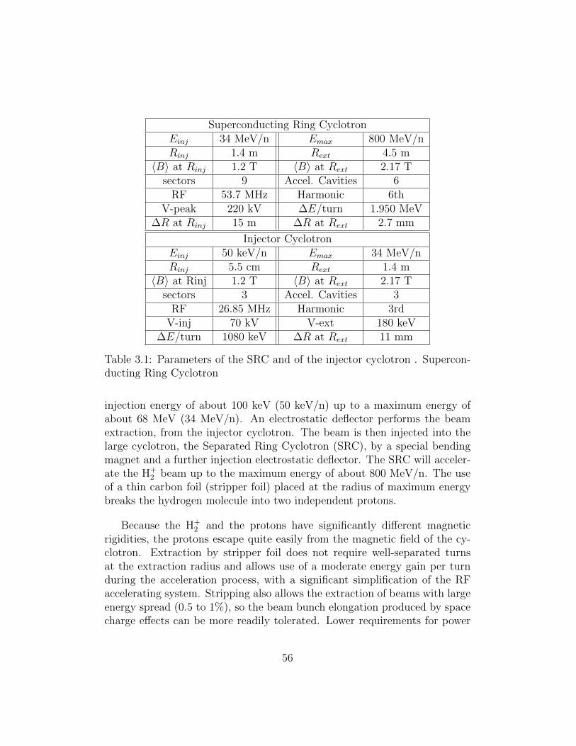
Superconducting Ring CyclotronEinj 34 MeV/n Emax 800 MeV/nRinj 1.4 m Rext 4.5 m
〈B〉 at Rinj 1.2 T 〈B〉 at Rext 2.17 Tsectors 9 Accel. Cavities 6
RF 53.7 MHz Harmonic 6thV-peak 220 kV ∆E/turn 1.950 MeV
∆R at Rinj 15 m ∆R at Rext 2.7 mm
Injector CyclotronEinj 50 keV/n Emax 34 MeV/nRinj 5.5 cm Rext 1.4 m
〈B〉 at Rinj 1.2 T 〈B〉 at Rext 2.17 Tsectors 3 Accel. Cavities 3
RF 26.85 MHz Harmonic 3rdV-inj 70 kV V-ext 180 keV
∆E/turn 1080 keV ∆R at Rext 11 mm
Table 3.1: Parameters of the SRC and of the injector cyclotron . Supercon-ducting Ring Cyclotron
injection energy of about 100 keV (50 keV/n) up to a maximum energy ofabout 68 MeV (34 MeV/n). An electrostatic deflector performs the beamextraction, from the injector cyclotron. The beam is then injected into thelarge cyclotron, the Separated Ring Cyclotron (SRC), by a special bendingmagnet and a further injection electrostatic deflector. The SRC will acceler-ate the H+
2 beam up to the maximum energy of about 800 MeV/n. The useof a thin carbon foil (stripper foil) placed at the radius of maximum energybreaks the hydrogen molecule into two independent protons.
Because the H+2 and the protons have significantly different magnetic
rigidities, the protons escape quite easily from the magnetic field of the cy-clotron. Extraction by stripper foil does not require well-separated turnsat the extraction radius and allows use of a moderate energy gain per turnduring the acceleration process, with a significant simplification of the RFaccelerating system. Stripping also allows the extraction of beams with largeenergy spread (0.5 to 1%), so the beam bunch elongation produced by spacecharge effects can be more readily tolerated. Lower requirements for power
56

transferred inside each cavity increases both the reliability and the conver-sion efficiency from electrical- to beam-power, as well reducing the overallcost of the RF system.
The special duty cycle (100 µs Beam On, 400 µs Beam Off) and thehigh beam power required by the DAEδALUS experiment will produce aserious beam loading effect on the accelerating cavities. That is, when theleading edge of the 100 ms beam pulse enters the cavity the sudden draw ofpower drops the voltage and affects the balance between the electrode andthe supply. This beam-loading will produce a voltage and phase instabilitythat must be compensated. This level of compensation must be high if thebeam is extracted by electrostatic deflector (PSI solution). This is a muchless serious issue if the extraction is, instead, performed by a stripper foil.
The layout shown in Fig. 3.2 is an evolution of the previous INFN design,presented at EPAC 2000 [79]. The main difference is the reduction of numberof sectors, from 12 to 9, and also of the extraction radius, from 6 m to 4.5 m,with a relevant cost reduction. These changes are feasible for two reasons.First, the maximum proton energy for DAEδALUS is 800 MeV, compared to1000 MeV in the ADS design. Second, since 2000, RF cavities with doublegaps have been designed which achieve voltages as high as 200kV. Accordingto Fig. 3.2, these accelerating cavities have a spiralled shape that matchesthe shape of the sectors. At the same time the use of only 9 sectors allow touse of RF cavities with an electrode width of about 16◦, with a convenient6th harmonic driving frequency. In this condition the accelerating voltageacross a double gap cavity isVmax ∗ 2 ∗ sin(96/2) = 1.48Vmax. Therefore, adouble gap cavity driven with a voltage of 200 kV is equivalent to a single gapcavity driven at 300 kV. The greatest advantage of the double gap cavitiesversus the single gap cavity or pill box cavity is that their ends exceed theinjection and extraction radius by only about 10 cm. The pill box cavity, forexample, needs an extra length at the entrance and at the extraction side ofabout 1 m. Moreover, the double gap cavities can be designed to producean acceleration voltage that increases with radius, while the pill box cavitieshave their maximum voltage just at the middle between the injection andextraction radius.
The acceleration of H+2 requires a magnetic field two times higher than for
protons; fortunately this is not a serious problem if superconducting coils areused. Generally, it is quite difficult to achieve the required isochronous fieldfor a ring using superconducting coils wrapped around the iron pole. Themore elegant solution is the use of the so-called “S-coils.” These are a pair
57

of superconducting coils wrapped around the pole/yoke and perpendicularto the median plane, outside of the extraction radius. This solution allowsfor more free space among the sectors, and for the cryostat of the supercon-ducting coils to be completely in the outer region, without any interferencewith the cavities and the accelerated beam. Preliminary evaluations by 3DMafia code were done to verify the feasibility of this Cyclotron.
The injector cyclotron will be designed scaling up the commercial cy-clotron TR-30 of the EBCO company (1.2 mA) or the C-30 of the IBAcompany (1mA). Both of these cyclotrons are able to deliver proton beamsat 30M eV and were designed to be compact, and highly efficient. In our casewe face the problem of accelerating a beam current which is about 5 timehigher, so the space charge effects will be serious. To overcome this problemwe plan to inject the H+
2 beam at energy of 100 keV and to use 3 RF accelerat-ing cavities to minimize the turn number in the injection cyclotron. The useof 3 sectors and of an extraction radius about double that of the commercialproton cyclotrons, allows more room for the RF cavities as well as use ofan acceleration voltage higher than 100 kV even at the injection radius. Weexpect that this cyclotron should be able to deliver a beam current of H+
2 ashigh as 5 mA, assuming a 100% duty cycle, or 1 mA with a 20% duty cycle.With respect to the space charge effects, we have to consider that the per-veance3 of a proton beam and an H+
2 beam with the same energy is the sameif we work at low energy (E <100 MeV). Therefore, the emittance of a H+
2
beam at 100 keV is the same or better than the emittance of a proton beamat the same energy. Moreover, proton sources are generally able to producehigh beam currents of H+
2 . In the present case, we need an H+2 source able
to deliver a beam current of about 33 mA. The injector cyclotron, equippedwith a simple buncher, should be able to catch and accelerate about 15%of the injected beam. This means that about 28 mA of H+
2 beam with anenergy of 100 keV (2.8 kWatt) will be lost in the first turn. The effect ofthis power loss on the superconducting materials needs to be considered, butbecause of the low energies, this does not result in high activation.
At DAEδALUS, for Phase 1, we could install 1, 1 and 2 accelerators at the1.5 km, 8 km and 20 km locations, respectively. This is slightly different fromour base design in that it supplies 1.5 MW,1.5 MW and 3 MW, respectively.
3The value of perveance is a measure of the significance of space charge effects on themotion of the beam.
58
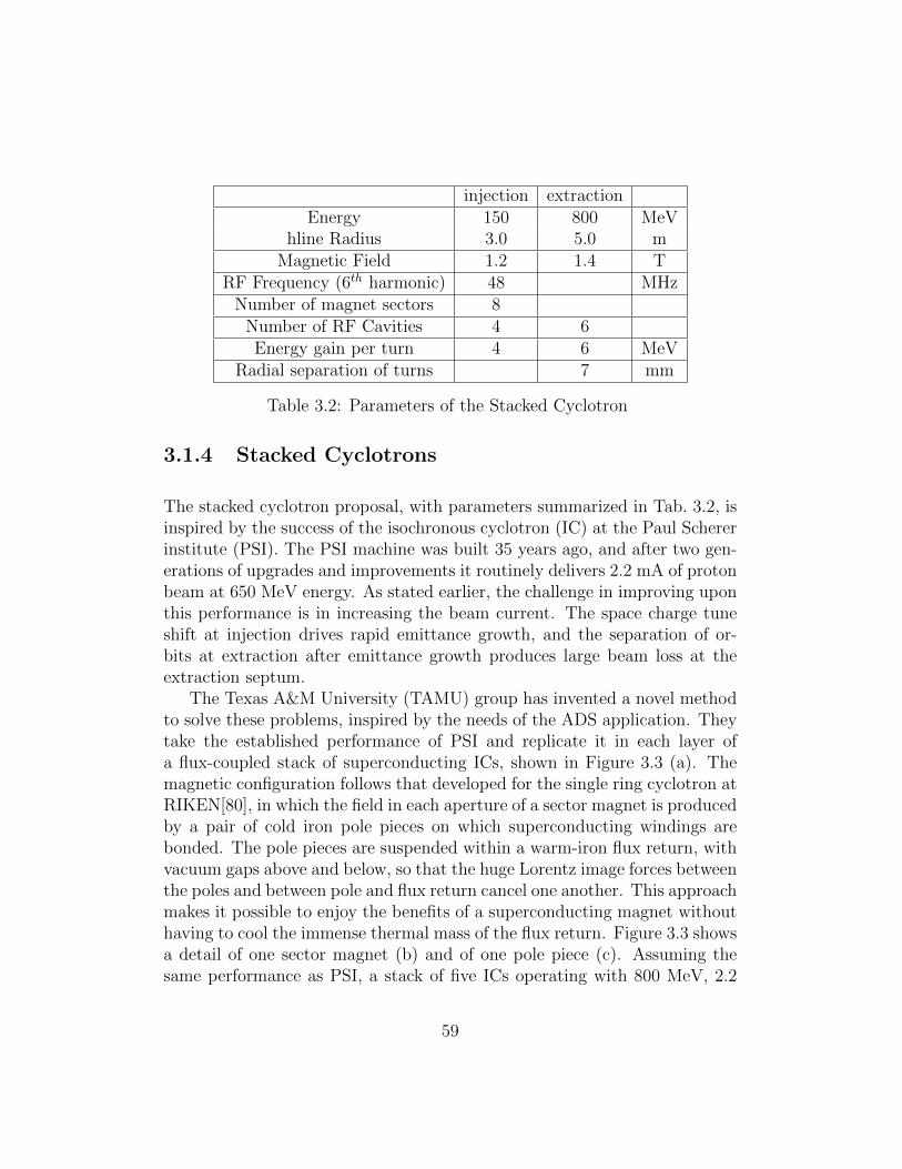
injection extractionEnergy 150 800 MeV
hline Radius 3.0 5.0 mMagnetic Field 1.2 1.4 T
RF Frequency (6th harmonic) 48 MHzNumber of magnet sectors 8
Number of RF Cavities 4 6Energy gain per turn 4 6 MeV
Radial separation of turns 7 mm
Table 3.2: Parameters of the Stacked Cyclotron
3.1.4 Stacked Cyclotrons
The stacked cyclotron proposal, with parameters summarized in Tab. 3.2, isinspired by the success of the isochronous cyclotron (IC) at the Paul Schererinstitute (PSI). The PSI machine was built 35 years ago, and after two gen-erations of upgrades and improvements it routinely delivers 2.2 mA of protonbeam at 650 MeV energy. As stated earlier, the challenge in improving uponthis performance is in increasing the beam current. The space charge tuneshift at injection drives rapid emittance growth, and the separation of or-bits at extraction after emittance growth produces large beam loss at theextraction septum.
The Texas A&M University (TAMU) group has invented a novel methodto solve these problems, inspired by the needs of the ADS application. Theytake the established performance of PSI and replicate it in each layer ofa flux-coupled stack of superconducting ICs, shown in Figure 3.3 (a). Themagnetic configuration follows that developed for the single ring cyclotron atRIKEN[80], in which the field in each aperture of a sector magnet is producedby a pair of cold iron pole pieces on which superconducting windings arebonded. The pole pieces are suspended within a warm-iron flux return, withvacuum gaps above and below, so that the huge Lorentz image forces betweenthe poles and between pole and flux return cancel one another. This approachmakes it possible to enjoy the benefits of a superconducting magnet withouthaving to cool the immense thermal mass of the flux return. Figure 3.3 showsa detail of one sector magnet (b) and of one pole piece (c). Assuming thesame performance as PSI, a stack of five ICs operating with 800 MeV, 2.2
59

(a) (b)
(c)
Figure 3.3: The design of the stacked cyclotron. a) The overall design; b)detail of one sector magnet; c) detail of one pole piece.
mA would provide the proton beam needed for DAEδALUS. Targeting thefive beams in a symmetric pattern on each beam dump should significantlysimplify the design and operation of the beam dump by limiting the localenergy density. Each element of the flux-coupled IC is, in effect, a close cousinof the PSI IC, except with higher injection and extraction energies, and theuse of superconducting magnet coils and superconducting RF cavities.
The design of the superconducting RF cavity was a particular challenge.It operates at 58 MHz (6th harmonic of the cyclotron frequency), and if itwere an empty cavity it would be much larger than what is needed to fitwithin the space between ICs in the flux-coupled stack. The TAMU groupinvented a dielectric-loaded resonator that fits in the required space, as shownin Fig. 3.4. It should be capable of 1 MV accelerating voltage and excellentmode stability. This is the one element of the flux-coupled IC stack thatrequires long-lead R&D to design, build, and test a prototype to validate thedesign.
In related research, the Cyclotron Institute at Texas A&M Universityoperates a superconducting cyclotron complex for nuclear research, and iscurrently upgrading the complex to re-accelerate radioactive nuclei using itsoriginal Cu-coil cyclotron. The Nuclear Engineering Department at TexasA&M University is interested in collaborating with the Accelerator Research
60
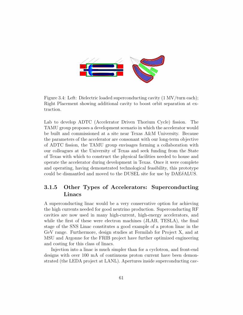
Figure 3.4: Left: Dielectric loaded superconducting cavity (1 MV/turn each);Right Placement showing additional cavity to boost orbit separation at ex-traction.
Lab to develop ADTC (Accelerator Driven Thorium Cycle) fission. TheTAMU group proposes a development scenario in which the accelerator wouldbe built and commissioned at a site near Texas A&M University. Becausethe parameters of the accelerator are consonant with our long-term objectiveof ADTC fission, the TAMU group envisages forming a collaboration withour colleagues at the University of Texas and seek funding from the Stateof Texas with which to construct the physical facilities needed to house andoperate the accelerator during development in Texas. Once it were completeand operating, having demonstrated technological feasibility, this prototypecould be dismantled and moved to the DUSEL site for use by DAEδALUS.
3.1.5 Other Types of Accelerators: SuperconductingLinacs
A superconducting linac would be a very conservative option for achievingthe high currents needed for good neutrino production. Superconducting RFcavities are now used in many high-current, high-energy accelerators, andwhile the first of these were electron machines (JLAB, TESLA), the finalstage of the SNS Linac constitutes a good example of a proton linac in theGeV range. Furthermore, design studies at Fermilab for Project X, and atMSU and Argonne for the FRIB project have further optimized engineeringand costing for this class of linacs.
Injection into a linac is much simpler than for a cyclotron, and front-enddesigns with over 100 mA of continuous proton current have been demon-strated (the LEDA project at LANL). Apertures inside superconducting cav-
61

ities are very large, typically 10 cm or more, so beam loss during accelerationis a much easier problem to solve. Extraction is also certainly not the prob-lem it is with cyclotrons. One drawback is the large footprint required. Thesecond, which accelerator physicists are working to address, is the high costof the systems.
An interesting opportunity might exist for working with the medical-isotopes community for developing a mutually-beneficial design. A seriousproblem exists in the US today regarding a steady, reliable supply of 99Mo,an isotope used in approximately 50,000 nuclear medicine procedures per dayin the US alone. This isotope is abundantly produced as a fission fragmentfrom neutron irradiation of highly-enriched uranium (HEU). There are noreactors in the US capable of supplying the year-round quantity of the iso-tope required, and considering the problems in the US associated with HEUreactors, this is not likely to change anytime soon. As a consequence, thesupply of the isotope comes from three aging reactors, one in Canada (cur-rently shut down) and two in Europe (both facing significant maintenanceproblems).
An interesting accelerator design has been proposed by the Physics Di-vision of Argonne National Lab, which would use a multi-megawatt protonbeam (at an energy close to 1 GeV) to produce neutrons in a heavy-metalblanket that would then bombard a small core of HEU from which the 99Mowould be extracted. The production from this accelerator would be capableof satisfying the entire US demand for the isotope, using less than half of itsbeam capacity.
3.1.6 Neutrino Source Design
The neutrino source for the DAEδALUS experiment will be a beam stop forthe proton beam. The beam stop will have a series of important functions,all of which require design considerations. First, the beam stop producesthe mesons which in turn either capture without decay, come to rest anddecay, or escape the beam stop altogether and decay; all decays produceneutrinos. The design of the beam stop can affect the neutrino flux byaltering the relative likelihood of these processes. Second, the beam stopdissipates the ∼1 MWatt energy of the beam, dissipating it into heat ina controlled fashion. Third, the outer portions of the beam stop containsthe significant flux of neutrons and gamma rays produced by interactions ofthe proton beam with the inner core, of importance not only for personnel
62
protection but also for limiting dose on nearby equipment and the watertable. High-power beam stops for proton accelerators have been designed fora variety of experiments [81, 82, 83, 84, 85], providing significant guidancein all three of these considerations. Each design goal of the beam stop isdiscussed in turn.
3.1.6.1 Neutrino Flux
The beam stop produces positive and negative pions and no kaons due tothe below-threshold kinetic energy of the incident proton beam. With ap-propriate geometric design, 98% of pions come to rest in the beam stop,with only ∼ 2% escaping laterally or longitudinally [86]. Neutrinos resultpredominantly from the decays π+ → µ + νµ, µ+ → νµνee
+ for pions andmuons coming to rest within the beam stop. The charge-conjugate decays aresuppressed because all but ∼ 5× 10⁻⁴ of π− are captured on nuclei withoutdecaying, and even the µ− from the few remaining π− → µ−νµ decays havean increased likelihood for capture without decay for heavy nuclei [87]. Tocontrol the neutrino flux, it is important to reduce or understand the mesonleakage from the beam stop which results in decays-in-flight to neutrinos,albeit at higher neutrino energies than those from the stopped pion decaychain, and it is important to reduce or understand the residual decays of non-captured µ− → e−νeνµ which produce an anti electron-neutrino backgroundto the oscillation search.
We propose to study a beam stop with an inner core composed of graphiteslabs stacked longitudinally along the beam axis. A significant amount ofdata exists [88, 89, 90, 91] for pion production on nuclei, particularly forcarbon. These data, along with information from Monte Carlo simulations[32, 33], indicate that, at a beam energy of 800 MeV, the number of neutri-nos produced is νµ/p ≈ 0.172, while the ratio π+/π− ≈ 4.5. Furthermore,the moderate atomic number Z = 6 produces a significant capture rate forµ−, reducing the νe contamination in the beam. With better optimization,one should be able to further reduce the wrong-sign neutrino contaminationrelative to the LANL beam stop.
Design considerations for the beam stop will include possible considera-tion of larger Z absorber plates embedded in the beam stop to reduce wrong-sign neutrino contamination, and the specification of the lateral dimensionsof the beam stop which controls meson leakage and the decay-in-flight com-ponent of the beam. Past experiments suggest that the uncertainty in these
63

components is 2-5% and in the overall neutrino flux is of order 11% [92], soit is of some use to reduce the background fluxes.
3.1.6.2 Thermal Analysis
The conceptual design of a beam dump for pion production from a high-current proton beam has been studied. It consists of a water-cooled stainless-steel or copper tube centered on the beam axis which contains a set ofgraphite disks or slabs. The disks near the beam entrance have concen-tric holes forming a re-entrant hole for the beam to spread the beam energyloss into the depth of the dump (see Figure 3.5, left). The energy depositedby the beam in the graphite disks is conducted radially to the surroundingwater-cooled lines. Such lines can be shrink-fit to the exterior of the graphitedisks, or, as in the case of the NuMI beam stop, the water cooling lines areclamped into the slabs of graphite for thermal contact (see Figure 3.5, right).The re-entrant hole is shaped in such a way as to keep the temperature con-stant over the re-entrant hole surface assuming constant temperature at thecooling tube. A more sophisticated design in which the cooling tube is ta-pered radially with respect to the beam axis such as to keep the heat fluxdensity constant over the tube between the beam entrance and the end ofthe re-entrant hole in addition to keeping the re-entrant hole temperatureuniform was also studied.
Assuming a circular double-Gaussian proton beam profile of r.m.s. radiusσ and exponential proton energy deposition in graphite with a interactionlength L, examples for a cylindrical and a tapered beam dump were eval-uated for the following parameters typical for a DAEδALUS beam stop:beam power = 1 MWatt, beam radius R.M.S. σ = 5 cm, graphite density= 1.75g/cm3, L = 50 cm, diameter of cooling channel = 30 cm, diameterof re-entrant hole=11.4 cm, cooling water = 100◦C. The resulting shapes ofa cylindrical and a tapered beam dump are shown in Figure 3.6. The totallength of the beam stop is constrained by the depths of the re-entrant holesplus the range of protons in graphite (125cm for 700MeV protons). Fig-ure 3.6 shows the result of thermal calculations for the beam stop. As withthe NuMI design, the present concept has the advantage of keeping watercooling lines out of the shower profile of the beam [93, 94]. A significantadvantage over other beam stop designs, however, is that the re-entrant holereduces the temperature at the center of the core by spreading out the inter-actions of the proton beam. To minimize sublimation from the hot graphite
64

Beam
Absorber
σ
σ
r `
dEdr `
r `rº
rº
R
R
Z(r)
Cooling
z ` z zº
Figure 3.5: (top) Conceptual design of a beam stop with tapered entrancehole for the proton beam. The shape of the entrance hole produces a constanttemperature profile along the length of the beam stop. (bottom) Conceptualdesign from the NuMI beam for establishing thermal contact between theslabs of the beam stop core to water cooling lines kept external to the beamprofile which involves sandwiching the cooling lines into channels betweenadjacent bolted slabs of the beam stop.
65

Composite Beam Dump
Cooling Surface 40º C
Copper
Graphite
σ
360º C
1250º C
Figure 3.6: Graph of the temperature profile in the beam stop. The verticalaxis is the radius away from the beam axis and the horizontal axis is longi-tudinal depth within the beam stop. Two curves are shown, one at the inneredge of the re-entrant hole which is maintained at a temperature 1250◦C andthe second at a line of constant temperature 360◦C.
slabs, they could be sputter-coated with a few microns of Molybdenum orTungsten eliminating the need for a beam window.
3.1.6.3 Radiation Protection
A significant design consideration will be the protection of personnel, equip-ment, and ground water from the radiation produced in the beam stop. It isenvisioned that the primary proton beam will be brought to the beam stopthrough a penetration in a shield wall which separates the proton extractionline from the target station. It is further envisioned that the water-cooledgraphite core of the beam stop is embedded in a larger structure of cast steeland concrete shielding blocks for attenuation of gamma rays and neutronsproduced in the beam stop. While the containment of the core inside sucha larger structure accentuates the need for thermal analysis, it is clear thatshielding thicknesses of ∼ 1 m of steel and ∼1 m of concrete is required just tokeep residual activity levels to 30 mR/hour after a year of 1 MWatt operationof the beam line [93]. Such will be the subject of simulation and calculation
66

work during the first year of DAEδALUS R&D. An additional concern will bethe mitigation of humidity and water in the target station area. A significantexperience from operation of the NuMI beam was that high humidity levelsdue to the below-grade location of the target station causes moisture captureand irradiation in the concrete shielding leading to high levels of tritium [95].Such humidity requires mitigation by dehumidification systems.
3.2 Detector Design
In designing DAEδALUS, we have adhered closely to the proposed largewater Cherenkov detector design. As with many of the low energy (<100MeV) analyses, this experiment requires Gd-doping and benefits from goodphotocathode coverage. We consider progress on these issues in this section.
3.2.1 Gd Doping
In order to detect IBD events, the DAEδALUS detector must be doped withthe neutron capture agent gadolinium (Gd). Gd offers two essential advan-tages over the competing process of hydrogen capture: it reduces the capturetime for the neutron generated in the IBD interaction from 200 µsec to about30 µsec , and the energy release from the capture interaction is higher - 8MeV compared with 2.2 MeV for hydrogen. These twin benefits provide aclean tag for the time correlated positron and neutron which make up theIBD signal.
Gd-doping is a familiar technology for antineutrino detection, having beenimplemented in numerous liquid scintillator experiments, including DoubleChooz [96], SONGS1 [97], and others. Stable operation over 1 year timescales has been demonstrated in these 1-10 ton scale liquid scintillator detec-tors.
Though well understood in small (by DAEδALUS standards) scintillatordetectors Gd-doping has been only partially demonstrated for large waterCherenkov detectors. LLNL has built and successfully operated 1-5 tonscale water detectors doped with 0.1% − 0.2% concentrations of Gd [98].These detectors have shown both the expected time correlations and the in-creased energy output from the neutron capture event using tagged neutron(Americium-Beryllium, AmBe) calibration sources. A 250 kg detector alsoempirically demonstrated the long term compatibility (1 year time scale) of
67

GdCl3 compounds with acrylic4. Implementation of these detectors is un-derway for nonproliferation applications that require large solid angle andefficient neutron detection.
In addition to these small scale performance tests, a test was performed atthe SuperKamiokande experiment, in which a small sealed vessel of Gd-dopedwater was lowered to the center of the detector [99] . The vessel also con-tained a tagged AmBe source, so that the neutron emission time was knownto within a few ns. The significance of this test is that the large water volumeguaranteed full containment of the Gd-capture gamma-ray shower. By com-paring with the well-tuned Superkamiokande energy calibration, it was foundthat approximately 50% of the shower energy is detectable in the Cherenkovlight emission channel. ( 4.3 MeV of energy out of an available 8 MeV fromthe capture gamma-ray shower.) The missing energy is a limitation imposedby physics that would be present even with perfect light collection. It occursbecause not all of the Compton electrons generated by the gamma-ray inter-actions are above the 0.78 MeV threshold for Cherenkov light production.In a set of soak tests related to this experiment, the compound Gd2(S04)3was found to be most compatible with the structural materials exposed tothe water-Gd solution.
While these tests are all encouraging for a large scale Gd-doped detec-tor, important R&D steps remain in order to demonstrate successful oper-ation at the 150,000 ton scale required for DAEδALUS (and LBNE). TheR&D program is derived from a set of physics requirements defined for theLBNE water detectors, which include a Gd-doping option. The table inFigure 3.7. taken from an LBNE project planning document [100], summa-rizes these requirements. The requirements are essentially identical to thoseneeded for DAEδALUS, though some relaxation of constraints could arisein DAEδALUS, due to the different event rates. DAEδALUS will considerwhich if any elements of the LBNE Gd doping strategy would need to bemodified on signal to background or cost grounds.
From the physics requirements, a set of research and development prior-ities have been identified. The steps listed below are part of the larger workplan for the overall LBNE water detector development program. DAEδALUSwill benefit from the overlap in detector needs of the two proposed experi-ments.
4In this detector, the entire detector interior was constructed of acrylic in order toreduce the likelihood of contamination/clouding from leached materials.
68

Capacity 3 cavities having 130 kTon of water each, or 2 tanks having 190 kTon each. a) One Treatment system for filling and recirculating a cavity and b) Separate filling and recirculating systems.
Scientific Competitiveness
Quality ASTM Type 1 and should include uranium removal and membrane final degasification.
Water transparency to Cherenkov light
Recirculation-only systems
In addition to microfiltration, should have sterilization, de-ionization, degasification, and chiller stages.
Optimize cost, allowing [re]chilling of partially filled cavity
Fill and Recirculation system
Depth Filter, a Carbon filter, a Softener, and a Reverse Osmosis unit, in addition to the stages required for recirculation.
Recirculation rate
300 gal/min
Fill rate 250 gal/min <3 months to fill Temperature Achieve a water temperature of 13o C over a 6 month period, which
should start at the beginning of the fill. The system should maintain the temperature of 13o C in the steady state operational period after the first 6 months.
Suppress biological growth to maintain transparency and reduce scatterig
Dissolved oxygen
<(?) 0.06 mg/liter.
Light transmission
Sterilization UV treatment Suppress biological growth
Fill Capacity 130kT per 3 months Timeliness Location of Water system
Adjacent to the detector at the 4850 foot level in the Homestake mine.
Reduce system complication
Instrumentation Sufficient instrumentation so that its health and basic control functions can be accessed remotely
Safety
Drainage Water Treatment Plant shall have the capability of draining the tanks at a rate of >250 gal/min to a facility supplied pump located on the same level. The draining system shall provide treatment to the water from the tanks so that it can be discharged into the local environment.
Environmental safety
OPTION: Recirculation Rate
600 or 1200 gal/min Water purity in system may require more frequent cleaning.
OPTION: Th and U removal
The plant should optionally provide uranium and thorium removal to U < 1.4 x 10⁻¹⁵ g/g and Th < 8.3 x 10⁻¹⁶ g/g.
Solar and Supernovae physics neutrino physics.
OPTION: Gd Compound
add 0.2% of Gadolinium compound to the water in the tanks to make the Water Cherenkov Detector sensitive to neutrons. The recirculation system should be able to clean the water to the levels specified above and to return it to the tanks maintaining the Gadolinium concentration. The drainage system should be able to remove the Gadolinium compound from the water when the tanks are drained.
Neutron detection for Solar and Supernovae physics, neutrino physics.
Figure 3.7: A list of basic requirements for the LBNE water systems, in-cluding the Gd doping option. This table is extracted from [100]
69
• demonstration that the water can be purified sufficiently even in thepresence of the Gd compound, which would normally be removed inthe purification process, and
• demonstration of long term compatibility of all exposed structural ma-terials with the Gd-water solution, and completion of a downselectionprocess for the choice of Gd-bearing chemical compound;
• demonstration that the attenuation length of the water is not com-promised directly by the Gd-solution or by leaching from structuralmaterials;
• demonstration of scaling of the Gd purification process, including demon-stration that Gd can be kept uniformly dissolved throughout the de-tector on time scales compatible with the water circulation and purifi-cation rate.
The LBNE work plan elements relating to Gd-doped detector R&D aredescribed briefly in the following sections. DAEδALUS will join forces withthe rest of the LBNE team to support studies of the Gd doping option forthe DUSEL WC detectors.
In addition to the US LBNE effort, a 200 ton scale Gd-doped detector andaccompanying filtration system is being built in Japan [101]. This detector,known as EGADS, will help answer several of the outstanding questionsregarding Gd-doping of detectors.
3.2.1.1 Water Purification in the Presence of Gd
The LBNE collaboration has a significant effort invested in developing a largescale purification system that is compatible with the use of a Gd dopant. The’standard’ purification system for large water detectors, such as that usedfor the SuperK detector, must be modified to allow introduction of purifiedGd after cleaning of the water. A flow chart for one proposed purificationmethod, developed at UC Irvine, is shown in Figure 3.8. The basic idea is toremove a Gd concentrate from the partially cleaned water, pass the Gd-freewater through additional purification steps, separately remove Uranium andThorium contaminants from the Gd concentrate, and recombine the purifiedGd concentrate with the purified water. The first elements of this processhave been demonstrated in a lab-scale system at UC Irvine. Research is
70
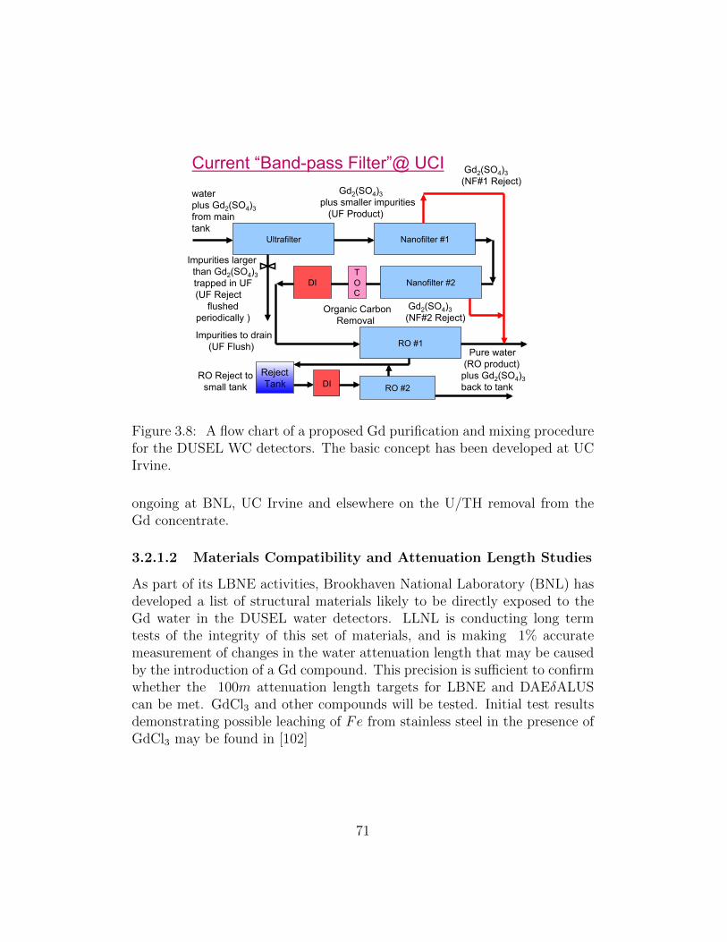
Ultrafilter Nanofilter #1
RO #1 Impurities to drain
(UF Flush) Pure water (RO product) plus Gd2(SO4)3 back to tank
water plus Gd2(SO4)3 from main tank
Gd2(SO4)3 (NF#1 Reject)
Gd2(SO4)3 plus smaller impurities (UF Product)
Impurities larger than Gd2(SO4)3
trapped in UF (UF Reject
flushed periodically )
Nanofilter #2 DI
Current “Band-pass Filter”@ UCI
RO Reject to small tank
Reject Tank DI RO #2
Gd2(SO4)3 (NF#2 Reject)
T O C
Organic Carbon Removal
Figure 3.8: A flow chart of a proposed Gd purification and mixing procedurefor the DUSEL WC detectors. The basic concept has been developed at UCIrvine.
ongoing at BNL, UC Irvine and elsewhere on the U/TH removal from theGd concentrate.
3.2.1.2 Materials Compatibility and Attenuation Length Studies
As part of its LBNE activities, Brookhaven National Laboratory (BNL) hasdeveloped a list of structural materials likely to be directly exposed to theGd water in the DUSEL water detectors. LLNL is conducting long termtests of the integrity of this set of materials, and is making 1% accuratemeasurement of changes in the water attenuation length that may be causedby the introduction of a Gd compound. This precision is sufficient to confirmwhether the 100m attenuation length targets for LBNE and DAEδALUScan be met. GdCl3 and other compounds will be tested. Initial test resultsdemonstrating possible leaching of Fe from stainless steel in the presence ofGdCl3 may be found in [102]
71

3.2.1.3 Scaling of Water Purification Systems in the Presence ofGd
In addition to defining a process for maintaining water purity in the presenceof Gd, the LBNE collaboration is working on the engineering aspects ofscaling the system to work with 150 kT mass detectors. Important elementsinclude the throughput of filtration systems and pumps, the specific layoutof the DUSEL caverns and water supply lines, and uniformity of mixing ofthe Gd in the water. Leaks in the detector are also far more important ina Gd-doped detector, because the underground sites will not allow directdischarge of Gd-doped water to drainage systems. Since prior detectors suchas Superkamiokande have had water losses, leak tightness must be improved.
The EGADS experiment in Japan will address several of the above R&Dquestions simultaneously, using a fully functional 200 ton scale detector andselective filtration system. In particular, EGADs goals are to study the rateat which Gd can be introduced into the water, the uniformity of Gd mixingin the water, the Gd removal process, the selective water filtering process,and materials effects in an integrated detector. (It will not directly addressthe U/Th removal process).
3.2.1.4 Conclusions for Gd Doping and Detector Scaling
The underlying physics of Gd-doped water detectors is now well established.The R&D program described above, is being pursued by LBNE and by theEGADS experiment in Japan. The program directly addresses the outstand-ing engineering questions that must be answered in order to achieve 150 ktonoperation of a Gd-doped detector.
3.2.2 Photocathode Coverage
In terms of photocathode coverage, DAEδALUS’ requirements are motivatedin principal by the need for efficient triggering at low visible energies, accurateenergy reconstruction, and accurate reconstruction of the out-going leptonscattering angle. Efficient triggering and vertex reconstruction is necessary toobserve the 8 MeV gamma cascade from the neutron capture on Gd charac-teristic of the IBD signal. Further, since the size of the δCP conversion effectin Eq. 2.3 is coupled to the amount of interference between the two neu-trino mass splittings, accurate energy reconstruction is important to extract
72
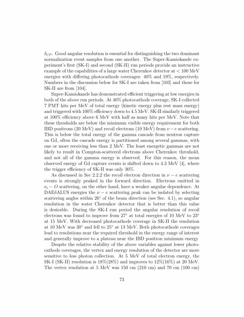
δCP . Good angular resolution is essential for distinguishing the two dominantnormalization event samples from one another. The Super-Kamiokande ex-periment’s first (SK-I) and second (SK-II) run periods provide an instructiveexample of the capabilities of a large water Cherenkov detector at < 100 MeVenergies with differing photocathode coverages: 40% and 19%, respectively.Numbers in the discussion below for SK-I are taken from [103] and those forSK-II are from [104].
Super-Kamiokande has demonstrated efficient triggering at low energies inboth of the above run periods. At 40% photocathode coverage, SK-I collected7 PMT hits per MeV of total energy (kinetic energy plus rest mass energy)and triggered with 100% efficiency down to 4.5 MeV. SK-II similarly triggeredat 100% efficiency above 6 MeV with half as many hits per MeV. Note thatthese thresholds are below the minimum visible energy requirement for bothIBD positrons (20 MeV) and recoil electrons (10 MeV) from ν−e scattering.This is below the total energy of the gamma cascade from neutron captureon Gd, often the cascade energy is partitioned among several gammas, withone or more receiving less than 2 MeV. The least energetic gammas are notlikely to result in Compton-scattered electrons above Cherenkov threshold,and not all of the gamma energy is observed. For this reason, the meanobserved energy of Gd capture events is shifted down to 4.3 MeV [4], wherethe trigger efficiency of SK-II was only 30%.
As discussed in Sec 2.2.2 the recoil electron direction in ν − e scatteringevents is strongly peaked in the forward direction. Electrons emitted inνe− O scattering, on the other hand, have a weaker angular dependence. AtDAEδALUS energies the ν − e scattering peak can be isolated by selectingscattering angles within 26◦ of the beam direction (see Sec. 4.1), so angularresolution in the water Cherenkov detector that is better than this valueis desirable. During the SK-I run period the angular resolution of recoilelectrons was found to improve from 27◦ at total energies of 10 MeV to 23◦
at 15 MeV. With decreased photocathode coverage in SK-II the resolutionat 10 MeV was 30◦ and fell to 25◦ at 13 MeV. Both photocathode coverageslead to resolutions near the required threshold in the energy range of interestand generally improve to a plateau near the IBD positron minimum energy
Despite the relative stability of the above variables against lower photo-cathode coverages, the vertex and energy resolution of the detector are moresensitive to less photon collection. At 5 MeV of total electron energy, theSK-I (SK-II) resolution is 18%(28%) and improves to 12%(16%) at 20 MeV.The vertex resolution at 5 MeV was 150 cm (210 cm) and 70 cm (100 cm)
73

20302010
3 sit
es o
pera
tiona
l,
Contract for Phase 1
Cyclotrons(mid & far)
2020
First roundprototyping is complete
Begin Phase 0:Cyclotronin near hall
“Phase 0”: near physics & learn about the
machine
“Phase 1”: Discover δ
at 3σ
Contract for Phase 2
Cyclotrons(positions TBD from
Phase 1 data)
“Phase 2”: Measure δprecisely
“CD
-1 le
vel”
Cos
t Esti
mat
e
Figure 3.9: A possible plan for the staging DAEδALUS
at 10 MeV.Current designs for the DUSEL water Cherenkov detector propose pho-
tocathode coverages between 30 and 40%. The latter is expected to providesufficient performance for DAEδALUS while SK-II level coverage is likely in-sufficient for reconstructing the Gd capture gammas from IBD events. Choos-ing the middle ground, 30% coverage, though providing improved vertex andangular resolution, may also suffer from inefficient triggering of these signalevents.
3.3 A Three-Phase Implementation Plan
We are developing our plans in coordination with the DUSEL Management.We propose a three-phase plan for staging the experiment, summarized inFig. 3.9. Before the CP-violation studies begin, we propose a Phase 0 wherewe learn to run a single accelerator on-site. This would allow for near-accelerator physics to begin. At the same time, it allows us to understand
74

!!"#$
%&'()*$!+,-&'.)-$
/+0-)$1'2(3-4$
5'))$1'2(3-4$
67,8$9+:)*$;<<=$>?70$$
@AB$).,C+D-$+D,-)$
E*E<<$.:?-,F,'.:?$
+D,-)$
;E<$273-)$'C$?,7G)$
@H$)&+G)$+:?$I7:J-)$
K,'$L':?'$
M337)':$
",+D0$
N'3?$5.:$
#+,8$
Figure 3.10: Sanford Lab footprint, showing the Kirk Adit and Oro Hondosites.
important aspects of operation. Phase 1 and 2 represent the CP-violationstudies periods.
For the Phase 0 site, we propose the area next to the entrance to the 300 Lcampus. This is called the Kirk Adit, and is labeled “Kirk Fans, 300 L Adit”on Fig. 3.10. This site is located just below the Yates shaft, at the base of a300 ft rise, and 1.5 km from the detector. The two photographs in Fig. 3.11show a portion of the space available. There is an open space available whichis large enough for the accelerator (left photograph). However, it would bebest if the unused fan building (right photograph) could be removed, as thisallows more space. The entrance to the 300 L is obscured by the car in theleft photograph. Sufficient power and water are available at the site. Theentrance road would need improvements in the first 30 feet. However, the300 L entrance may be used as a construction entrance, in which case theroad improvements would be in place before the accelerator building wouldbe built.
An alternative location for the on-site accelerator is at the Oro Hondo
75

Figure 3.11: Region in front of the Kirk Adit. Left: a portion of the openspace available. The 300 L entrance is obscured by the car. To the right ofthe person is the fan building, not shown. Right: the building housing theunused fans.
Figure 3.12: The Oro Hondo substation site. Left: An area which could becleared for the accelerator building; Right: view to the Yates shaft from thesite.
76

substation (marked Oro Hondo on Fig. 3.10.) There is a flat area which couldbe easily cleared of small trees which would accommodate the acceleratorbuilding (Fig. 3.12, left). The area has power; water availability will need tobe investigated. The road leading to the area is well maintained, because itleads to the Oro Hondo substation. The drawback of this site is that it is farfrom the Yates shaft (see Fig. 3.12, right, which shows the view to the Yatesshaft). Thus it would not permit a 300 L physics program.
We do not proceed to CD-1 for Phase 1 until 2015 or later. This sched-ule allows time to negotiate the off-site locations. Several locations withdisturbed land could be considered. By this timeframe, information will beavailable on sin2 2θ13 from Double Chooz, Daya Bay and T2K. These datacan be used to inform our design.
77
Chapter 4
Impact On Other Analyses
In this section, we describe how DAEδALUS coordinates with other analysesalready under consideration for the large water Cherenkov detector. Wefirst show the benefits of the beam for calibration. We then discuss theimpact of the beam events on other studies, especially those in particle-astrophysics, which are in the same energy range. It should be noted thatthere are DAEδALUS collaborators participating in each of these areas ofstudy, and this allows good coordination between our design and those ofthe other analysis groups.
4.1 Neutrino-electron Events as a Calibration
Source
Neutrino-electron events from the near accelerator offer a high statistics“standard candle” for calibration of the detector to the 1% level up to anenergy of 55 MeV. This calibration standard will be valuable to all of thelarge detector experiments.
The neutrino-electron scattering process has a well-defined cross-section,as was discussed in Section 2.2, when we considered these events for the nor-malization sample. There is a net 1% theoretical error in the normalizationof the cross section. However, there is negligible theoretical error in both theshape of the visible energy distribution and the scattering angle as a functionof visible and neutrino energy. As a result, neutrino-electron scatters providea very useful sample for calibration.
The visible energy distribution of neutrino-electron scatters from a decay
78

nu-e Events for 1 acc for 10yrs at 1.5km
0
1000
2000
3000
4000
5000
6000
0 5 10 15 20 25 30 35 40 45 50 55
Evis = Eelectron (MeV)
Even
ts
nue-eTotal nu-enumu-eanumu-e
Figure 4.1: Top curve (magenta): visible energy distribution for neutrino-electron scatters from a decay-at-rest beam. Lower curves: the νe (blue), νµ(olive) and νµ (brown) contributions.
at rest beam is shown in Fig. 4.1, top curve (magenta). The number ofevents corresponds to 10 years of running at 1.5 km. The lower curves showthe individual contributions of the three flavors in the beam: νe (blue), νµ(brown), and νµ (olive). Neutrino-electron scattering is dominated by thecharged current νe-electron interaction. The scatters of the monoenergeticνµ (from π+ decay) make an important contribution below 30 MeV. The νµscatters are a small contribution.
Fig. 4.2 illustrates the strength of the neutrino-electron data for energycalibration. The plot shows the ratio of data with a 1% energy offset to theprediction, with the statistics for the full 10 year run. The poor χ2/DOFindicates that calibration is required. This shows that this data set is sensitiveat the ∼1% level. Note that we allow the overall normalization to float sincethis data set is used to set the normalization of our analysis and that thiscalibration relies only upon shape.
There is a strong energy-angle dependence in the kinematics of neutrino-electron scattering. This is shown in Fig. 4.3 (right). As discussed in Sec-
79
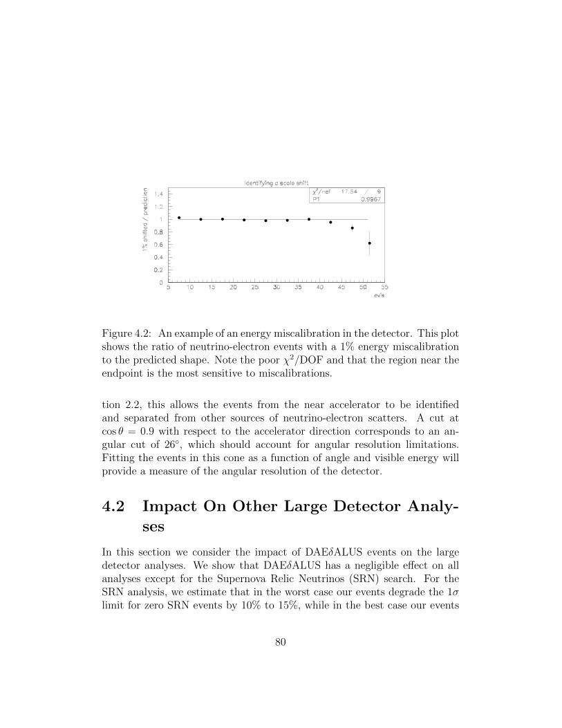
Figure 4.2: An example of an energy miscalibration in the detector. This plotshows the ratio of neutrino-electron events with a 1% energy miscalibrationto the predicted shape. Note the poor χ2/DOF and that the region near theendpoint is the most sensitive to miscalibrations.
tion 2.2, this allows the events from the near accelerator to be identifiedand separated from other sources of neutrino-electron scatters. A cut atcos θ = 0.9 with respect to the accelerator direction corresponds to an an-gular cut of 26◦, which should account for angular resolution limitations.Fitting the events in this cone as a function of angle and visible energy willprovide a measure of the angular resolution of the detector.
4.2 Impact On Other Large Detector Analy-
ses
In this section we consider the impact of DAEδALUS events on the largedetector analyses. We show that DAEδALUS has a negligible effect on allanalyses except for the Supernova Relic Neutrinos (SRN) search. For theSRN analysis, we estimate that in the worst case our events degrade the 1σlimit for zero SRN events by 10% to 15%, while in the best case our events
80

0.80
0.82
0.84
0.86
0.88
0.90
0.92
0.94
0.96
0.98
1.00
0 5 10 15 20 25 30 35 40 45 50 55Eν (MeV)
cos θ
e
2.557.5101520
Ee (MeV)
Figure 4.3: The unique angle vs. visible-energy correlation for neutrino-electron scattering at each neutrino energy.
provide a tool to improve the limit by 20% to 30%. We note that all of theseanalyses benefit from the neutrino-electron calibration sample provided byDAEδALUS.
4.2.0.1 High Energy Analyses: Long Baseline, Atmospheric andProton Decay
The following analyses have signatures which require visible energy well above55 MeV – the maximum for DAEδALUS – and/or event signatures which areeasily distinguishable from DAEδALUS:
• Long Baseline Neutrino Oscillations, which employs a neutrino fluxabove 300 MeV.
• Atmospheric Neutrino Studies, which rely on νµ charged-current inter-actions above ∼ 100 MeV.
81

• Proton Decay, where the signatures are e+π0 and K+ν. Both cases havea high visible energy and very different signature than DAEδALUS-induced interactions.
The proton decay analysis has overlapping interest with DAEδALUS be-cause an important proton decay signature includes observation of a lowenergy photon. A 6 MeV photon accompanies proton decay in the oxygennucleus, and thus provides a coincident signal that reduces background. Thisis of similar energy to the photons from the Gd-capture used by DAEδALUS.Both experiments will therefore require similar photocathode coverage.
4.2.0.2 Solar Analyses
DAEδALUS has a negligible effect on the solar neutrino analyses. The nearaccelerator produces a neutrino-electron scattering signal during the 20%time period that it is running. However, these events are cut by a cos θ <0.9 requirement, where θ is the angle with respect to the near acceleratordirection. This reduces the effective fiducial volume by 5%, but only whenthe accelerator is running. With only this cut, the net effect is a 1% lossof data. This can be cut to 0.5% if one simply requires that the acceleratorrun mainly when the sun is in the opposite hemisphere, which will place theaccelerator events far outside of the angular cut for solar events.
On the other hand, the DAEδALUS events provide a very nice, well-defined, high statistics sample at low electron visible energies (see Fig. 4.1).Along with its value for calibration, already discussed, this sample allows ameasurement of the efficiency for reconstructing neutrino-electron scatters atlow energies. This may be valuable to the statistics-limited solar neutrinostudies.
4.2.0.3 Supernova Burst Analyses
The Supernova Neutrino Burst Analysis focuses on the same energy range asDAEδALUS. A supernova neutrino signal will involve mostly IBD events (thecontribution of ν-e scatters is a few percent, and from other interactions isnot more than 10%) . For an observed nearby supernova burst, which shouldinvolve at least 24,000 events in about 10 seconds in 300 kton for a supernovawithin 20 kpc (edge of the Galaxy), the expected background of Daedalusevents is negligible. However, DAEδALUS events may be a background forextragalactic SN burst search analyses, which look for multiple events within
82
about a ten second time window, or look for single events in coincidence withexternal triggers such as optical supernovae or gravitational waves. In tenyears of running there will be ∼5000 fake bursts of two or more DAEδALUSevents. By requiring IBD events for the supernova burst search, this back-ground can be greatly reduced to the order of 1 in the 10-year period. For an∼2 hour time window in coincidence with a visible extragalactic supernovaevent, there will be on average about 3 Daedalus events, but the mean num-ber of IBD events in such a window will be 0.04. This background can bereduced to zero by eliminating beam-on time from the supernova analysis,resulting in a some livetime loss.
4.2.0.4 Supernova Relic Neutrino Analyses
The one analysis for which the DAEδALUS events have a substantial overlapis the Supernova Relic Neutrino (SRN) search. We have been in contact withthe leaders of the SRN analysis, in order to understand our impact [105, 106].The conclusion of this interaction is that the two analysis groups can co-existand, in fact, help one another.
Both analyses rely on IBD event signatures which will occur as singleevents (as opposed to bursts) spread over time. The SRN analysis focusesprimarily on the 10 to 20 MeV range [106]. Above 20 MeV, invisible muons,which are below Cherenkov threshold, but stop and decay, dominate theSRN background. Below 10 MeV, natural background sources and reactorneutrinos dominate. The SRN 10 to 20 MeV window is adjacent to theDAEδALUS 20 to 55 MeV signal window. The DAEδALUS accelerators doproduce a small number of events below 20 MeV.
To assess the impact of DAEδALUS events on this analysis, considerthe case of no SRN signal. We consider the case of 5% and 10% systematicerrors, to bracket a reasonable range for the analysis. We consider two energybins, from 10 to 15 MeV, and from 15 to 20 MeV. We quote the factorby which the 1σ sensitivity of the SRN signal will change, for a δCP = 0and sin2 2θ13 = 0.04 DAEδALUS signal. If the accelerators are not gatedout, then the well-measured DAEδALUS signal can be subtracted, but thatsubtraction will have an error which impacts the SRN analysis. Rows 1 and 2of Tab. 4.1 give the factor by which the sensitivity will change. An alternativeis to gate out the 60% of the time that the three DAEδALUS acceleratorsare running. This weakens the SRN 1σ sensitivity by lowering the statistics
83

Energy bin 10-15 MeV 15-20 MeVDAEδALUS, 5% SRN sys 1.14 1.24DAEδALUS, 10% SRN sys 1.09 1.14
Gating out DAEδALUS, 5% SRN sys 1.12 1.19Gating out DAEδALUS, 10% SRN sys 1.08 1.12
Likelihood, gating out DAEδALUS, 5% sys 0.5 0.59
Table 4.1: Factor by which the 1σ sensitivity will change for the SRN analysis,for various scenarios of including DAEδALUS, assuming a signal of δCP = 0and sin2 2θ13 = 0.04. See text for explanation of scenarios.
for a potential SRN signal. The effect of this is shown in rows 3 and 4. Inthe energy range of the proposed analysis, in either case, the DAEδALUSimpact is only a 10% to 20% worsening of the sensitivity.
On the other hand, the DAEδALUS events provide a substantial trueIBD event sample in the 30 to 55 MeV range. This can be compared to thebeam-off events in the 30 to 50 MeV range which are dominated by an orderof magnitude by invisible muon events. These two samples can be playedagainst one another to develop an algorithm which accepts true IBD eventsat high efficiency while rejecting invisible muon events. If one imagines de-veloping a likelihood that rejects 50% of the invisible muon background whilemaintaining nearly 100% efficiency for IBD events, then the 1σ sensitivityfor the SRN substantially improves. This is shown by row 5 of Tab. 4.1.Thus, depending on the quality of the likelihood which can be developed,the DAEδALUS events can provide a significant tool for improvement of theSRN analysis.
From this, one can see that the SRN and DAEδALUS analyses workwell together. DAEδALUS provides extra motivation for Gd-doping andmanpower for developing ideas like the likelihood analysis. In the otherdirection, DAEδALUS is relying on the development work on Gd-dopingwhich was developed by the SRN community [3] and is now driven by theSRN and non-proliferation analysis groups.
84

Chapter 5
Conclusion
The DAEδALUS experiment offers an opportunity to both expand and en-hance the neutrino physics program at DUSEL. Using a a set of low-costcompact cyclotron sources, the experiment is able to provide a high-intensity,well-understood source of neutrinos for various studies from neutrino oscilla-tions to nuclear spin structure measurements. Each stopped pion producedby incident protons leads to three different flavor neutrinos allowing the fluxto be measured with little systematic uncertainty. In addition, the energyspectrum of the neutrinos is also completely determined by the weak de-cay of the stopped pion and stopped daughter muon. Thus, a stopped-pionneutrino beam provides an ideal laboratory for making precision normalizedmeasurements in the region from 10 MeV to 55 MeV.
For neutrino oscillation measurements of θ13 or δCP , DAEδALUS wouldsearch for νµ −→ νe oscillations where the νe is detected through the inverse-beta-decay process where positron and neutron are detected and associatedthrough a delayed coincidence. To enhance the neutron capture and detec-tion, the detector will need to be doped with Gd. For the running scenariopresented in this EOI with multiple MW-cyclotrons at distance of 1.5, 8, and20 km from a 300 kton water detector, DAEδALUS has excellent discoveryand measurement potential for θ13 and δCP that is comparable and com-plementary to the sensitivity of currently planned LBNE experiment. Also,since DAEδALUS can provide a high-statistics antineutrino sample, the com-bination of DAEδALUS with ν−only running of LBNE leads to an enhancedsensitivity (by a factor 2) for observing CP violation and measuring δCP .
A broad suite of non-oscillation physics experiments are also possible us-ing the large LBNE detector or small dedicated detectors placed close to the
85

near (1.5 km) neutrino source. Coherent neutrino-nucleus scattering mea-surements using a 1 ton liquid argon detector placed 30 m from the sourcecan be used to make measurements of the weak mixing angle or to searchfor non-standard interactions. A near source detector could also be used tomeasure cross sections relevant to astrophysical processes, supernova explo-sions and nucleosynthesis, and to supernova detectors. The high neutrinorates also lead to the possibility of searching for neutrino magnetic momentsor making measurements of strange quark spin asymmetry, ∆s.
The DAEδALUS experiment has two important requirements: the devel-opment of low-cost, high-power cyclotrons and the addition of Gd doping forthe large LBNE detector. Significant R&D progress is being made in both ofthese areas and the prospects are good that attractive technical solutions willcome about. If these requirements can be met, the DAEδALUS plus nearsource experiments will greatly enlarge the physics program at DUSEL. Forthese reasons, we request that the DAEδALUS experiment be incorporatedas a possible option in the DUSEL planning with the understanding that theexperiment would go forward when technical issues are addressed.
86
Bibliography
[1] J. M. Conrad and M. H. Shaevitz. A New Method to Search for CPviolation in the Neutrino Sector. 2009.
[2] V. Barger et al. Report of the US long baseline neutrino experimentstudy. 2007.
[3] John F. Beacom and Mark R. Vagins. GADZOOKS! Antineutrinospectroscopy with large water Cherenkov detectors. Phys. Rev. Lett.,93:171101, 2004.
[4] H. Watanabe et al. First Study of Neutron Tagging with a WaterCherenkov Detector. 2008.
[5] S. Dazeley, A. Bernstein, N. S. Bowden, and R. Svoboda. Observationof Neutrons with a Gadolinium Doped Water Cerenkov Detector. Nucl.Instrum. Meth., A607:616–619, 2009.
[6] Atsuko Kibayashi and for the Super-Kamiokande Collaboration.Gadolinium Study for a Water Cherenkov Detector. 2009.
[7] Gina Ramieka. Private Communication. 2009.
[8] Joachim Kopp. Sensitivity Studies for LBNE.
[9] Sanjib K. Agarwalla, Patrick Huber, Jonathan M. Link, and DebabrataMohapatra. A new approach to anti-neutrino running in long baselineneutrino oscillation experiments. 2010.
[10] A. Bandyopadhyay et al. Physics at a future Neutrino Factory andsuper-beam facility. Rept. Prog. Phys., 72:106201, 2009.
87

[11] Mauro Mezzetto. Next Challenge in Neutrino Physics: the theta(13)Angle. 2009.
[12] The Neutrino Scientific Assessment Group. Recommendations to theDepartment of Energy and the National Science Foundation on a Fu-ture U.S. Program in Neutrino Oscillations. 2008.
[13] The P5 Panel. Report of the Particle Physics Project PrioritizationPanel,. 2008.
[14] Hitoshi Murayama and T. Yanagida. Leptogenesis in supersymmetricstandard model with right- handed neutrino. Phys. Lett., B322:349–354, 1994.
[15] Ernest Ma and Utpal Sarkar. Neutrino masses and leptogenesis withheavy Higgs triplets. Phys. Rev. Lett., 80:5716–5719, 1998.
[16] Sacha Davidson and Alejandro Ibarra. A lower bound on the right-handed neutrino mass from leptogenesis. Phys. Lett., B535:25–32, 2002.
[17] Junpei Harada. Neutrino mixing and CP violation from Dirac-Majorana bimaximal mixture and quark-lepton unification. Europhys.Lett., 75:248–253, 2006.
[18] Zhi-zhong Xing, He Zhang, and Shun Zhou. Nearly tri-bimaximal neu-trino mixing and CP violation from mu - tau symmetry breaking. Phys.Lett., B641:189–197, 2006.
[19] Hiroshi Nunokawa, Stephen J. Parke, and Jose W. F. Valle. CP Vio-lation and Neutrino Oscillations. Prog. Part. Nucl. Phys., 60:338–402,2008.
[20] Thomas Schwetz, M. A. Tortola, and Jose W. F. Valle. Three-flavourneutrino oscillation update. New J. Phys., 10:113011, 2008.
[21] G. L. Fogli, E. Lisi, A. Marrone, A. Palazzo, and A. M. Rotunno. SNO,KamLAND and neutrino oscillations: theta(13). 2009.
[22] Thomas Schwetz. Neutrino oscillations: Current status and prospects.Acta Phys. Polon., B36:3203–3214, 2005.
88

[23] Patrick Huber, Manfred Lindner, Thomas Schwetz, and Walter Win-ter. First hint for CP violation in neutrino oscillations from upcomingsuperbeam and reactor experiments. JHEP, 11:044, 2009.
[24] Kendall Brianna McConnel Mahn and Michael H. Shaevitz. Compar-isons and combinations of reactor and long-baseline neutrino oscillationmeasurements. Int. J. Mod. Phys., A21:3825–3844, 2006.
[25] Stefan Schonert. Neutrinoless double beta decay. J. Phys. Conf. Ser.,203:012014, 2010.
[26] D. S. Ayres et al. NOvA proposal to build a 30-kiloton off-axis detectorto study neutrino oscillations in the Fermilab NuMI beamline. 2004.
[27] Hisakazu Minakata. Long Baseline Neutrino Experiments with Two-Detector Setup. Int. J. Mod. Phys., A23:3388–3394, 2008.
[28] Patrick Huber, Joachim Kopp, Manfred Lindner, Mark Rolinec, andWalter Winter. New features in the simulation of neutrino oscillationexperiments with GLoBES 3.0. Comput. Phys. Commun., 177:432–438,2007.
[29] T. Araki et al. Measurement of neutrino oscillation with KamLAND:Evidence of spectral distortion. Phys. Rev. Lett., 94:081801, 2005.
[30] Y. Fukuda et al. Measurement of the flux and zenith-angle distributionof upward through-going muons by Super-Kamiokande. Phys. Rev.Lett., 82:2644–2648, 1999.
[31] I. Stancu et al. The OscSNS Whitepaper. D60, 2008.
[32] R. L. Burman, M. E. Potter, and E. S. Smith. MONTE CARLO SIM-ULATION OF NEUTRINO PRODUCTION BY MEDIUM- ENERGYPROTONS IN A BEAM STOP. Nucl. Instrum. Meth., A291:621–633,1990.
[33] R. L. Burman. Neutrino flux calculations for the ISIS spallation neu-tron facility. Nucl. Instrum. Meth., A368:416–424, 1996.
[34] P. Vogel and John F. Beacom. The angular distribution of the neutroninverse beta decay, anti-nu/e + p → e+ + n. Phys. Rev., D60:053003,1999.
89

[35] J. M. Conrad, J. M. Link, and M. H. Shaevitz. Precision measurementof sin**2(theta(W)) at a reactor. Phys. Rev., D71:073013, 2005.
[36] L. B. Auerbach et al. Measurement of electron-neutrino electron elasticscattering. Phys. Rev., D63:112001, 2001.
[37] W. C. Haxton. NEUTRINO REACTIONS ON OXYGEN ANDA PROPOSED MEASUREMENT OF THE WEINBERG ANGLE.Phys. Rev., C37:2660–2664, 1988.
[38] R. Lazauskas and C. Volpe. Neutrino beams as a probe of the nuclearisospin and spin- isospin excitations. Nucl. Phys., A792:219–228, 2007.
[39] W. C. Haxton. The Nuclear Response of Water Cherenkov Detectorsto Supernova and Solar Neutrinos. Phys. Rev., D36:2283, 1987.
[40] Weller H.R. Tilley, D.R. and C.M. Cheves. Energy levels of light nuclei,A = 16 (see Tab. 16.30). Nucl. Phys., A564, 1993.
[41] F. Ajzenberg-Selove and T. Lauritsen. Energy levels of light nuclei, a= 17 (see tab. 17.6). Nucl. Phys., 11, 1959, Revised Nov., 2008.
[42] F. Ajzenberg-Selove and T. Lauritsen. Energy levels of light nuclei, A= 18 (see Tab. 18.4). Nucl. Phys., A475, 1959, Revised Nov., 2008.
[43] Perry R.T Charlton W.S Wilson, W.B. and T.A. Parish. Sources:A code for calculating (alpha, n), spontaneous fission, and delayedneutron sources and spectra. Prog. in Nuc. Energy, 51:608, 2009.
[44] Y. Ashie et al. A Measurement of Atmospheric Neutrino OscillationParameters by Super-Kamiokande I. Phys. Rev., D71:112005, 2005.
[45] T. Adams et al. Terascale Physics Opportunities at a High Statistics,High Energy Neutrino Scattering Experiment: NuSOnG. Int. J. Mod.Phys., A24:671–717, 2009.
[46] F. James and M. Roos. Minuit: A System for Function Minimizationand Analysis of the Parameter Errors and Correlations. Comput. Phys.Commun., 10:343–367, 1975.
[47] Mary Bishai. Private Communication. 2009.
90

[48] Charles J. Horowitz, K. J. Coakley, and D. N. McKinsey. Supernovaobservation via neutrino nucleus elastic scattering in the CLEAN de-tector. Phys. Rev., D68:023005, 2003.
[49] K. Scholberg et al. The CLEAR Experiment. 2009.
[50] Kate Scholberg. Prospects for measuring coherent neutrino nucleuselastic scattering at a stopped-pion neutrino source. Phys. Rev.,D73:033005, 2006.
[51] G. P. Zeller et al. A precise determination of electroweak parametersin neutrino nucleon scattering. Phys. Rev. Lett., 88:091802, 2002.
[52] Vernon D. Barger, G. F. Giudice, and Tao Han. Some New Aspects ofSupersymmetry R-Parity Violating Interactions. Phys. Rev., D40:2987,1989.
[53] S. Davidson, C. Pena-Garay, N. Rius, and A. Santamaria. Present andfuture bounds on non-standard neutrino interactions. JHEP, 03:011,2003.
[54] J. Schechter and J. W. F. Valle. Neutrino Masses in SU(2) x U(1)Theories. Phys. Rev., D22:2227, 1980.
[55] P. S. Amanik and G. C. McLaughlin. Nuclear neutron form factor fromneutrino nucleus coherent elastic scattering. J. Phys., G36:015105,2009.
[56] K. Langanke et al. Electron capture rates on nuclei and implicationsfor stellar core collapse. Phys. Rev. Lett., 90:241102, 2003.
[57] W. R. Hix et al. The consequences of nuclear electron capture in corecollapse supernovae. Phys. Rev. Lett., 91:201102, 2003.
[58] A. Juodagalvis, K. Langanke, W. R. Hix, G. Martinez-Pinedo, andJ. M. Sampaio. Improved estimate of stellar electron capture rates onnuclei. 2009.
[59] Nu-SNS Proposal.
91

[60] G. C. McLaughlin. Neutrino nucleus cross section measurements usingstopped pions and low energy beta beams. Phys. Rev., C70:045804,2004.
[61] C. Frohlich et al. Neutrino-induced nucleosynthesis of A¿64 nuclei: Thenu p- process. Phys. Rev. Lett., 96:142502, 2006.
[62] L. T. Kizivat, G. Martinez-Pinedo, K. Langanke, R. Surman, and G. C.McLaughlin. Gamma-Ray Bursts Black hole accretion disks as a sitefor the vp-process. Phys. Rev., C81:025802, 2010.
[63] Gail C. McLaughlin and George M. Fuller. Evidence for an intense neu-trino flux during r process nucleosynthesis? Astrophys. J., 464:L143–L146, 1996.
[64] Y. Z. Qian, W. C. Haxton, K. Langanke, and P. Vogel. Neutrino-induced neutron spallation and supernova r- process nucleosynthesis.Phys. Rev., C55:1532–1544, 1997.
[65] P. Vogel and J. Engel. Neutrino Electromagnetic Form-Factors. Phys.Rev., D39:3378, 1989.
[66] G. Garvey, E. Kolbe, K. Langanke, and S. Krewald. Role of strangequarks in quasielastic neutrino scattering. Phys. Rev., C48:1919–1925,1993.
[67] R. Tayloe. A measurement of the strange quark contribution to thenucleon spin via neutrino nucleon elastic scattering. Nucl. Phys. Proc.Suppl., 105:62–65, 2002.
[68] M. B. Barbaro, A. De Pace, T. W. Donnelly, A. Molinari, and M. J.Musolf. Probing nucleon strangeness with neutrinos: Nuclear modeldependences. Phys. Rev., C54:1954–1969, 1996.
[69] F. T. Avignone, V. Gudkov, L. Chatterjee, Yu. Efremenko, andM. Strayer. ORLaND: A proposed facility to investigate neutrino prop-erties relevant to astrophysics. Nucl. Phys. Proc. Suppl., 91:113–119,2001.
[70] Timothy Antaya. Talk Given at the DAEδALUS Workshop, Feb. 2010.
92

[71] Robert Macek. Private Communication. 2009.
[72] Th. Stammbach et al. The feasibility of high power cyclotrons. Nucl.Instr. & Meth., B11, 1-4:1–7, 1996.
[73] H.G. Blosser and D.A. Johnson.
[74] H.G. Blosser et al. Advances in superconducting cyclotrons at nscl.Cyclotrons and Their Applications, Eleventh International Conference,pages 157–167, 1986.
[75] S. Zaremba W. Beeckman D. Vandeplassche M. abs P. VerbruggenW. Kleeven, S. Lucas and Y. Jongen. The self-extracting cyclotron.Cyclotrons and Their Applications, Sixteenth International Conference,AIP 0-7354-0044-X:69–73, 2001.
[76] W. Kleeven Y. Jongen and S. Zaremba. New cyclotron developmentsat iba. Cyclotrons and Their Applications, Seventeenth InternationalConference, pages 69–73, 2004.
[77] A.K. Ghosh et al. Dynamic stability threshold in high-performanceinternal-tin nb3sn superconductors for high field magnets. Supercond.Sci. Technol., 18:L5–L8, 2005.
[78] http://abe.web.psi.ch/accelerators/ringcyc.php.
[79] L. Calabretta et al. A Superconducting Ring Cyclotron To DeliverHight Intensity Proton Beams. Proceedings of EPAC 2000, page 917,2000.
[80] Kawaguchi et al. Design of the sector magnets for the riken supercon-ducting ring cyclotron, us particle accelerator conference, 1997. IEEE,1998.
[81] The T2K Experiment. http://jnusrv01.kek.jp/public/t2k/index.html.
[82] Experiments at the JPARC Hadron Hall. http://j-parc.jp/nuclpart/slowextracted e.html.
[83] Minos Experiment and the NuMI Beamline. http://www-numi.fnal.gov/.
93

[84] LANSCE Facility Status. http://lansceoperations.lanl.gov/.
[85] ISIS: A World Center for Neutrons and Muons.http://www.isis.stfc.ac.uk/index.html.
[86] R. L. Burman and W. C. Louis. Neutrino physics at meson factoriesand spallation neutron sources. J. Phys., G29:2499–2512, 2003.
[87] R. L. Burman and P. Plischke. Neutrino fluxes from a high-intensityspallation neutron facility. Nucl. Instrum. Meth., A398:147–156, 1997.
[88] J. F. Crawford et al. Measurement Of Cross-sections And AsymmetryParameters For The Production Of Ccharged Pions From Varius NucleiBy 585- MeV Protons. Phys. Rev., C22:1184–1196, 1980.
[89] D. R. F. Cochran et al. Production of charged pions by 730-MeVprotons from hydrogen and selected nuclei. Phys. Rev., D6:3085–3116,1972.
[90] P. Denes et al. Production Of Positive Pions By 800-MeV Protons OnCarbon. Phys. Rev., C27:1339–1341, 1983.
[91] N. J. Digiacomo et al. Inclusive Pion Production In 330-MeV, 400-MeV, And 500-MeV Proton Nucleus Collisions. Phys. Rev., C31:292–294, 1985.
[92] R. C. Allen et al. A Measuement Of The Neutrino Flux From AStopped Pion Source. Nucl. Instrum. Meth., A284:347, 1989.
[93] A. Wehmann. Fnal document numi-b-493. 1999.
[94] A.A. Abramov. Fnal document numi-b-652. 2000.
[95] J.Hylen. Fnal document numi-b-652. 2000.
[96] M. Apollonio et al. Limits on neutrino oscillations from the choozexperiment. Phys. Lett. B, pages 415–430, 1999.
[97] N. S. Bowden, A. Bernstein, M. Allen, J. S. Brennan, M. Cunningham,J. K. Estrada, C. M. R. Greaves, C. Hagmann, J. Lund, W. Mengesha,T. D. Weinbeck, and C. D. Winant. Experimental results from anantineutrino detector for cooperative monitoring of nuclear reactors.NIM A, 572:985–998, 2007.
94

[98] S. Dazeley, A. Bernstein, N.S. Bowden, and R. Svoboda. Observationof neutrons with a gadolinium doped water cherenkov detector. NIMA, 607:616–61, 2009.
[99] Hirokazu Ishino for the Super-Kamiokande Collaboration. Gadoliniumstudy for super-kamiokande, 2009.
[100] R. W. Kadel. Dusel long base line neutrino experiment (lbne) watersupply and requirements, v2. Technical report, LBL, 2010. DDRD-doc-392-v2.
[101] Mark Vagins. Gadzooks: Supernova neutrinos without the annoyingwait, 2010. http://theory.tifr.res.in/ jigsaw10/talks/vagins.pdf.
[102] W. Coleman, A. Bernstein, S. Dazeley, and R. Svoboda. Transparencyof 0.2% gdcl3 doped water in a stainless steel test environment. NIMA, 595:339–345, 2008.
[103] J. Hosaka et al. Solar neutrino measurements in Super-Kamiokande-I.Phys. Rev., D73:112001, 2006.
[104] J. P. Cravens et al. Solar neutrino measurements in Super-Kamiokande-II. Phys. Rev., D78:032002, 2008.
[105] John Beacom. Private Communications. 2009, 2010.
[106] Mark Vagins. Private Communication. 2010.
95