Embed Size (px)
Citation preview
D2D Resource Sharing and Beamforming
PhuongBang Nguyen
Department of Electrical EngineeringUniversity of San Diego, California
Fall 2012
PhuongBang Nguyen (UCSD) D2D Beamforming UCSD 2012 1 / 32
Outline
1 Introduction
2 Single Antenna Scenario (SISO)
3 Multiple Antenna Scenario (MIMO)
4 References
PhuongBang Nguyen (UCSD) D2D Beamforming UCSD 2012 2 / 32

Outline
1 Introduction
2 Single Antenna Scenario (SISO)
3 Multiple Antenna Scenario (MIMO)
4 References
PhuongBang Nguyen (UCSD) D2D Beamforming UCSD 2012 3 / 32

Project Outline
This presentation discusses the resource optimization problemin a Device-to-Device communications network.The problem is examined under several different settings:
I Single antenna, single carrier (Single-carrier SISO)I Single antenna, multiple carriers (Multi-carrier SISO)I Multiple antennas, single carrier (Single-carrier MIMO)
Only brief summaries are presented for the SISO cases.The MIMO case is discussed in detail in three sub-topics:
I Orthogonal BeamformingI Zero-forcing BeamformingI Tunable Beamforming
PhuongBang Nguyen (UCSD) D2D Beamforming UCSD 2012 4 / 32
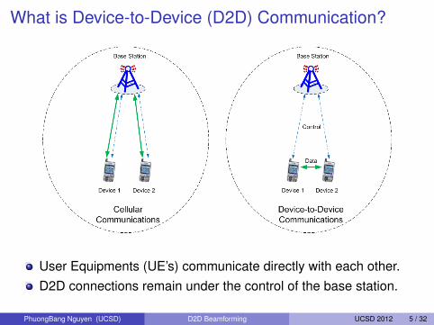
What is Device-to-Device (D2D) Communication?
User Equipments (UE’s) communicate directly with each other.D2D connections remain under the control of the base station.
PhuongBang Nguyen (UCSD) D2D Beamforming UCSD 2012 5 / 32
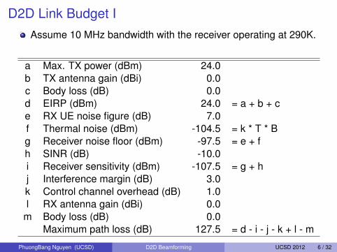
D2D Link Budget IAssume 10 MHz bandwidth with the receiver operating at 290K.
a Max. TX power (dBm) 24.0b TX antenna gain (dBi) 0.0c Body loss (dB) 0.0d EIRP (dBm) 24.0 = a + b + ce RX UE noise figure (dB) 7.0f Thermal noise (dBm) -104.5 = k * T * Bg Receiver noise floor (dBm) -97.5 = e + fh SINR (dB) -10.0i Receiver sensitivity (dBm) -107.5 = g + hj Interference margin (dB) 3.0k Control channel overhead (dB) 1.0l RX antenna gain (dBi) 0.0
m Body loss (dB) 0.0Maximum path loss (dB) 127.5 = d - i - j - k + l - m
PhuongBang Nguyen (UCSD) D2D Beamforming UCSD 2012 6 / 32
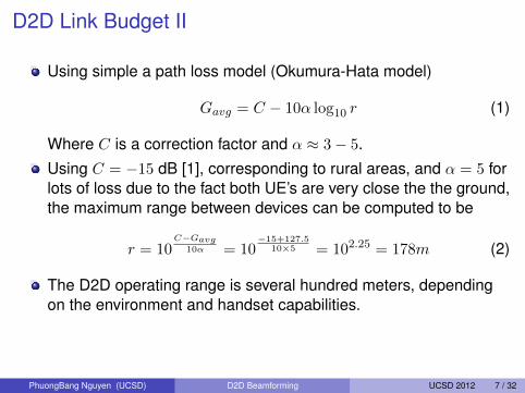
D2D Link Budget II
Using simple a path loss model (Okumura-Hata model)
Gavg = C − 10α log10 r (1)
Where C is a correction factor and α ≈ 3− 5.
Using C = −15 dB [1], corresponding to rural areas, and α = 5 forlots of loss due to the fact both UE’s are very close the the ground,the maximum range between devices can be computed to be
r = 10C−Gavg
10α = 10−15+127.5
10×5 = 102.25 = 178m (2)
The D2D operating range is several hundred meters, dependingon the environment and handset capabilities.
PhuongBang Nguyen (UCSD) D2D Beamforming UCSD 2012 7 / 32
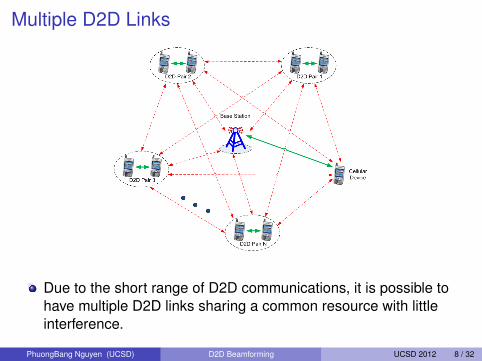
Multiple D2D Links
Due to the short range of D2D communications, it is possible tohave multiple D2D links sharing a common resource with littleinterference.
PhuongBang Nguyen (UCSD) D2D Beamforming UCSD 2012 8 / 32

Benefits and Challenges of D2D Communications
BenefitsI For the UE’s:
F Better throughputF Lower powerF Shorter delayF Transparent mode switching
I For the system:F Less relay load for the base stationsF Better channel resource reuse
I For the service provider:F Easier to plan access, investment and interference coordination in a
licensed band.F Resource can still be assigned to D2D in a dense network.
ChallengesI Peer DiscoveryI Mode SelectionI Interference Management/Coordination
PhuongBang Nguyen (UCSD) D2D Beamforming UCSD 2012 9 / 32

D2D Interference Scenarios
PhuongBang Nguyen (UCSD) D2D Beamforming UCSD 2012 10 / 32
Outline
1 Introduction
2 Single Antenna Scenario (SISO)
3 Multiple Antenna Scenario (MIMO)
4 References
PhuongBang Nguyen (UCSD) D2D Beamforming UCSD 2012 11 / 32
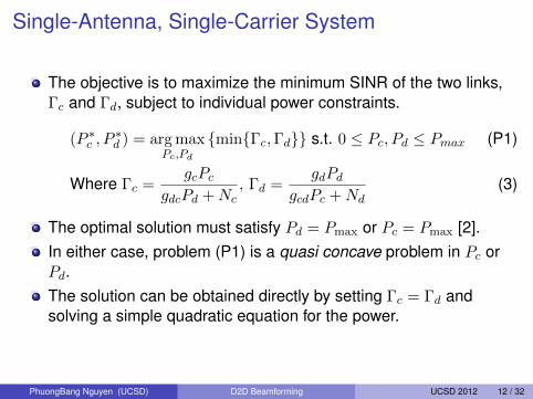
Single-Antenna, Single-Carrier System
The objective is to maximize the minimum SINR of the two links,Γc and Γd, subject to individual power constraints.
(P ∗c , P∗d ) = arg max
Pc,Pd
{min{Γc,Γd}} s.t. 0 ≤ Pc, Pd ≤ Pmax (P1)
Where Γc =gcPc
gdcPd +Nc, Γd =
gdPd
gcdPc +Nd(3)
The optimal solution must satisfy Pd = Pmax or Pc = Pmax [2].In either case, problem (P1) is a quasi concave problem in Pc orPd.The solution can be obtained directly by setting Γc = Γd andsolving a simple quadratic equation for the power.
PhuongBang Nguyen (UCSD) D2D Beamforming UCSD 2012 12 / 32

Single-Antenna, Multi-Carrier SystemWe joint-optimize over the shared set of N sub-carriers.
maxx,y
min {Rc, Rd} s.t. 1Tx ≤ P totc , 1Ty ≤ P tot
d (P2)
Rc,d ,N−1∑k=0
log2(1 + SINR(k)c,d ), xk , P (k)
c , yk , P(k)d (4)
Rewriting problem (P2) using a slack variable s, we have
maxx,y,s
{s} s.t. 1Tx ≤ P totc , 1Ty ≤ P tot
d (5)
s×N−1∏k=0
g(k)dc yk +N
(k)c
g(k)dc yk +N
(k)c + g
(k)c xk
≤ 1 (6)
s×N−1∏k=0
g(k)cd xk +N
(k)d
g(k)cd xk +N
(k)d + g
(k)d yk
≤ 1 (7)
This problem can be solved as a geometric program by usingmonomial approximation to the denominators of (6) and (7) [3].
PhuongBang Nguyen (UCSD) D2D Beamforming UCSD 2012 13 / 32
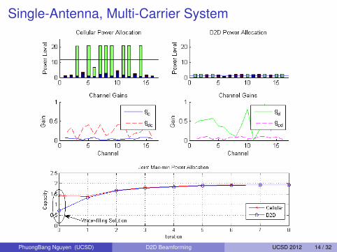
Single-Antenna, Multi-Carrier System
PhuongBang Nguyen (UCSD) D2D Beamforming UCSD 2012 14 / 32
Outline
1 Introduction
2 Single Antenna Scenario (SISO)
3 Multiple Antenna Scenario (MIMO)
4 References
PhuongBang Nguyen (UCSD) D2D Beamforming UCSD 2012 15 / 32
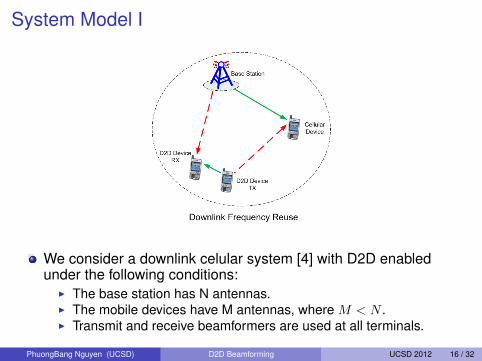
System Model I
We consider a downlink celular system [4] with D2D enabledunder the following conditions:
I The base station has N antennas.I The mobile devices have M antennas, where M < N .I Transmit and receive beamformers are used at all terminals.
PhuongBang Nguyen (UCSD) D2D Beamforming UCSD 2012 16 / 32

System Model II
The signals received at the D2D and cellular receivers are givenby
yd = uHd Hdvd
√Pdxd + uH
d Hcdvc
√Pcxc +Nd (8)
yc = uHc Hcvc
√Pcxc + uH
c Hdcvd
√Pdxd +Nc (9)
WhereI xc, xd are scalar transmit signals for the cellular and D2D linksI vc,vd and uc,ud are unit-norm transmit/receive beamformersI Pc, Pd are transmit powersI Hc,Hd are MIMO channel matrices for the direct paths, Hcd,Hdc
are channel matrices for the interference pathsI Nc ∼ N (0, σ2
c ) and Nd ∼ N (0, σ2d) are Gaussian noises.
PhuongBang Nguyen (UCSD) D2D Beamforming UCSD 2012 17 / 32

Problem FormulationConsider the following joint optimization problem
maxuc,ud,vc,vd,Pc,Pd
min {Γc,Γd} (P3)
s.t.: 0 ≤ Pc ≤ Pmaxc , 0 ≤ Pd ≤ Pmax
d
‖uc‖ = 1, ‖vc‖ = 1, ‖ud‖ = 1, ‖vd‖ = 1
Where
Γc =|uH
c Hcvc|2Pc
|uHc Hdcvd|2Pd + σ2c
=uHc (PcΦc)uc
uHc (PdΦdc + σ2c I)uc
(10)
Γd =|uH
d Hdvd|2Pd
|uHd Hcdvc|2Pc + σ2d
=uHd (PdΦd)ud
uHd (PcΦcd + σ2dI)ud
(11)
Φc = HcvcvHc HH
c , Φd = HdvdvHd HH
d
Φdc = HdcvdvHd HH
dc, Φcd = HcdvcvHc HH
cd
Problem (P3) is a non convex optimization problem.
PhuongBang Nguyen (UCSD) D2D Beamforming UCSD 2012 18 / 32
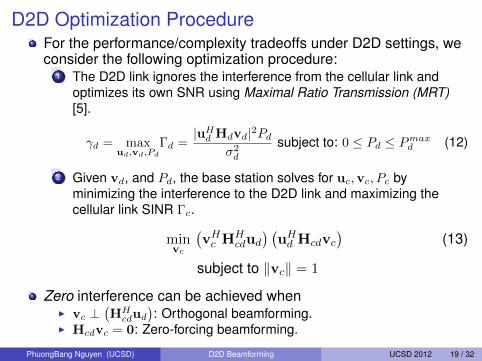
D2D Optimization ProcedureFor the performance/complexity tradeoffs under D2D settings, weconsider the following optimization procedure:
1 The D2D link ignores the interference from the cellular link andoptimizes its own SNR using Maximal Ratio Transmission (MRT)[5].
γd = maxud,vd,Pd
Γd =|uH
d Hdvd|2Pd
σ2d
subject to: 0 ≤ Pd ≤ Pmaxd (12)
2 Given vd, and Pd, the base station solves for uc,vc, Pc byminimizing the interference to the D2D link and maximizing thecellular link SINR Γc.
minvc
(vHc HH
cdud
) (uHd Hcdvc
)(13)
subject to ‖vc‖ = 1
Zero interference can be achieved whenI vc ⊥
(HH
cdud
): Orthogonal beamforming.
I Hcdvc = 0: Zero-forcing beamforming.
PhuongBang Nguyen (UCSD) D2D Beamforming UCSD 2012 19 / 32
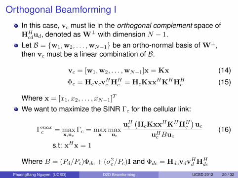
Orthogonal Beamforming I
In this case, vc must lie in the orthogonal complement space ofHH
cdud, denoted as W⊥ with dimension N − 1.Let B = {w1,w2, . . . ,wN−1} be an ortho-normal basis of W⊥,then vc must be a linear combination of B.
vc = [w1,w2, . . . ,wN−1]x = Kx (14)
Φc = HcvcvHc HH
c = HcKxxHKHHHc (15)
Where x = [x1, x2, . . . , xN−1]T
We want to maximize the SINR Γc for the cellular link:
Γmaxc = max
x,ucΓc = max
xmaxuc
uHc
(HcKxxHKHHH
c
)uc
uHc Buc
(16)
s.t: xHx = 1
Where B = (Pd/Pc)Φdc + (σ2c/Pc)I and Φdc = HdcvdvHd HH
dc
PhuongBang Nguyen (UCSD) D2D Beamforming UCSD 2012 20 / 32

Orthogonal Beamforming IILet y , B
12 uc, we have
Γmaxc = max
xmaxy
yH(B−
12
)HHcKxxHKHHH
c B− 1
2 y
yHy(17)
s.t: xHx = 1
Without changing the problem, we can constrain ‖y‖ = 1 and get
Γmaxc = max
xmaxy
yH(B−
12
)HHcKxxHKHHH
c B− 1
2 y (18)
s.t: xHx = 1,yHy = 1
⇔ Γmaxc = max
z{max
yyHzzHy} (19)
s.t: xHx = 1,yHy = 1
Where z ,(B−
12
)HHcKx
PhuongBang Nguyen (UCSD) D2D Beamforming UCSD 2012 21 / 32
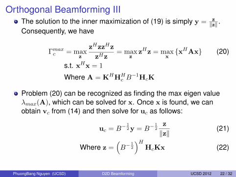
Orthogonal Beamforming IIIThe solution to the inner maximization of (19) is simply y = z
‖z‖ .Consequently, we have
Γmaxc = max
z
zHzzHz
zHz= max
zzHz = max
x{xHAx} (20)
s.t. xHx = 1
Where A = KHHHc B−1HcK
Problem (20) can be recognized as finding the max eigen valueλmax(A), which can be solved for x. Once x is found, we canobtain vc from (14) and then solve for uc as follows:
uc = B−12 y = B−
12
z
‖z‖(21)
Where z =(B−
12
)HHcKx (22)
PhuongBang Nguyen (UCSD) D2D Beamforming UCSD 2012 22 / 32

Zero-forcing Beamforming I
When N > M , it is possible to impose zero-forcing constraint onvc in order to eliminate interference to the D2D link.For the cellular link, we maximize its SINR and get the followingoptimization problem:
maxvc,uc
Γc = maxvc
maxuc
uHc Φcuc
uHc Buc
(23)
subject to: Hcdvc = 0 (24)‖vc‖ = 1 (25)
Constraint (24) means vc lies in the null space of Hcd. LetHcd = UΣVH be the singular decomposition of Hcd. A basis ofthe null space of Hcd is the last (N −R) columns of V, denoted asvR+1,vR+2, . . . ,vN , where R is the rank of Hcd.
PhuongBang Nguyen (UCSD) D2D Beamforming UCSD 2012 23 / 32

Zero-forcing Beamforming IIAs a result, vc is a linear combination of this basis:
vc = [vR+1,vR+2, . . . ,vN ]x = K′x (26)
Φc = HcvcvHc HH
c = HcK′xxHK′
HHH
c (27)
Where x = [x1, x2, . . . , xN−R]T
Consequently, we have:
maxx,uc
uHc
(HcK
′xxHK′HHHc
)uc
uHc Buc
(28)
subject to: ‖x‖ = 1
Problem (28) is identical to problem (16) in the OrthogonalBeamforming section with K′ instead of K.Hence, the solution x must be the max eigen vectorcorresponding to λmax(A′), where A′ = K′HHH
c B−1HcK
′. Thesolutions for uc and vc can be obtained in the same way.
PhuongBang Nguyen (UCSD) D2D Beamforming UCSD 2012 24 / 32
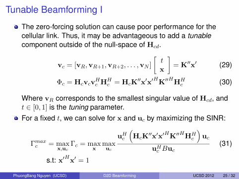
Tunable Beamforming I
The zero-forcing solution can cause poor performance for thecellular link. Thus, it may be advantageous to add a tunablecomponent outside of the null-space of Hcd.
vc = [vR,vR+1,vR+2, . . . ,vN ]
[tx
]= K′′x′ (29)
Φc = HcvcvHc HH
c = HcK′′x′x′
HK′′
HHH
c (30)
Where vR corresponds to the smallest singular value of Hcd, andt ∈ [0, 1] is the tuning parameter.For a fixed t, we can solve for x and uc by maximizing the SINR:
Γmaxc = max
x,ucΓc = max
xmaxuc
uHc
(HcK
′′x′x′HK′′HHHc
)uc
uHc Buc
(31)
s.t: x′H
x′ = 1
PhuongBang Nguyen (UCSD) D2D Beamforming UCSD 2012 25 / 32
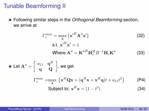
Tunable Beamforming II
Following similar steps in the Orthogonal Beamforming section,we arrive at
Γmaxc = max
x{x′HA′′x′} (32)
s.t. x′H
x′ = 1
Where A′′ = K′′H
HHc B−1HcK
′′ (33)
Let A′′ =
[a11 qH
q Q
], we get
Γmaxc =max
x
{xHQx + (qHx + xHq)t+ a11t
2}
(P4)
Subject to: xHx = (1− t2) (34)
PhuongBang Nguyen (UCSD) D2D Beamforming UCSD 2012 26 / 32
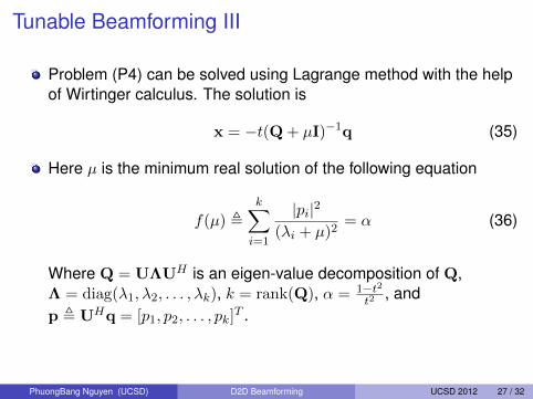
Tunable Beamforming III
Problem (P4) can be solved using Lagrange method with the helpof Wirtinger calculus. The solution is
x = −t(Q + µI)−1q (35)
Here µ is the minimum real solution of the following equation
f(µ) ,k∑
i=1
|pi|2
(λi + µ)2= α (36)
Where Q = UΛUH is an eigen-value decomposition of Q,Λ = diag(λ1, λ2, . . . , λk), k = rank(Q), α = 1−t2
t2, and
p , UHq = [p1, p2, . . . , pk]T .
PhuongBang Nguyen (UCSD) D2D Beamforming UCSD 2012 27 / 32

Tunable Beamforming IV
PhuongBang Nguyen (UCSD) D2D Beamforming UCSD 2012 28 / 32
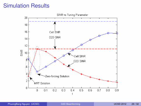
Simulation Results
PhuongBang Nguyen (UCSD) D2D Beamforming UCSD 2012 29 / 32

Outline
1 Introduction
2 Single Antenna Scenario (SISO)
3 Multiple Antenna Scenario (MIMO)
4 References
PhuongBang Nguyen (UCSD) D2D Beamforming UCSD 2012 30 / 32
References I
[1] H. Holma and A. Toskala, WCDMA for UMTS: HSPA Evolution andLTE.John Wiley & Sons, 2010.
[2] A. Gjendemsjo, G. E. Oien, and D. Gesbert, “Binary power controlfor multi-cell capacity maximization,” IEEE 8th Workshop on SignalProcessing Advances in Wireless Communications, pp. 1–5, Jun2007.
[3] M. Chiang, “Geometric programming for communications systems,”Foundations and Trends in Communications and InformationTheory, vol. 2, pp. 1–156, Aug 2005.
[4] B. Song, R. Cruz, and B. Rao, “Network duality for multiuser mimobeamforming networks and applications,” IEEE Transactions onCommunications, vol. 55, pp. 618–630, Mar 2007.
PhuongBang Nguyen (UCSD) D2D Beamforming UCSD 2012 31 / 32

References II
[5] T. K. Y. Lo, “Maximum ratio transmission,” IEEE Transactions onCommunications, vol. 47, pp. 1458–1461, Oct 1999.
PhuongBang Nguyen (UCSD) D2D Beamforming UCSD 2012 32 / 32