Embed Size (px)
Citation preview

http://www.woodonline.com
DOWNLOADABLE ONLINE WOODWORKING PLANS
®
Page 1 of 22
Cyclone dust collectors have beenused for decades in industrial applica-tions. They are compact, quiet, extremelyefficient and easy to service. Now, thesesame features that make cyclones soattractive to industry are available to thesmall-shop woodworker in a unit that isboth economical and easy to build.
Our system, intended for a small shop,is powered by a 850 cubic feet per minute(cfm), 1.5 horsepower blower. Ourcyclone will work for blowers rangingfrom 500 to 800 cfm, and was used suc-cessfully in both the WOOD® shop and inIdea Shop 3. This is the only size cyclonewe've built and tested. After publishingthe original how-to plans, we've had sev-eral requests for guidelines on buildinglarger units. For a unit with a larger blow-er, you'll need to increase the size of thecylinder, housing, cone, inlet, outlet, andfilter accordingly.
Cyclones are sized according to blow-er volume (cfm), so using a blower of adifferent capacity will require changes inthe size of the cyclone unit. Use the tableon the next page to size the sheet metalparts of the cyclone. The pattern for theinlet hole can be enlarged to match thelarger duct sized required with largerblowers. The wooden parts will be thesame shape as those in the plan, but you'llneed to increase the size of the parts ifyou plan on using a blower larger than800 cfm.
In a corner or against a wall, this highly efficientcyclone dust collector requires minimal space witheasy access to the waste can.
DP-00068 ©Copyright Meredith Corporation 1998
CycloneDUST-DEFYING
TM
Page 2 of 22
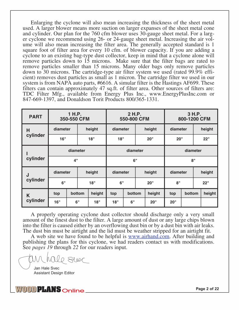
Enlarging the cyclone will also mean increasing the thickness of the sheet metalused. A larger blower means more suction on larger expanses of the sheet metal coneand cylinder. Our plan for the 760 cfm blower uses 30-gauge sheet metal. For a larg-er cyclone we recommend using 26- or 24-gauge sheet metal. Increasing the air vol-ume will also mean increasing the filter area. The generally accepted standard is 1square foot of filter area for every 10 cfm. of blower capacity. If you are adding acyclone to an existing bag-type dust collector, keep in mind that a cyclone alone willremove particles down to 15 microns. Make sure that the filter bags are rated toremove particles smaller than 15 microns. Many older bags only remove particlesdown to 30 microns. The cartridge-type air filter system we used (rated 99.9% effi-cient) removes dust particles as small as 1 micron. The cartridge filter we used in oursystem is from NAPA auto parts, #6616. A simular filter is the Hastings AF699. Thesefilters can contain approximately 47 sq.ft. of filter area. Other sources of filters are:TDC Filter Mfg., available from Energy Plus Inc., www.EnergyPlusInc.com or 847-669-1397, and Donaldson Torit Products 800/365-1331.
A properly operating cyclone dust collector should discharge only a very smallamount of the finest dust to the filter. A large amount of dust or any large chips blowninto the filter is caused either by an overflowing dust bin or by a dust bin with air leaks.The dust bin must be airtight and the lid must be weather stripped for an airtight fit.
A web site we have found to be helpful is www.airhand.com. After building andpublishing the plans for this cyclone, we had readers contact us with modifications.See pages 19 through 22 for our readers input.
Jan Hale Svec
Assistant Design Editor
PART1 H.P.
350-550 CFM2 H.P.
550-800 CFM3 H.P.
800-1200 CFM
Hcylinder
Icylinder
Jcylinder
Kcylinder
diameter height diameter height diameter height
diameter diameter diameter
diameter height diameter height diameter height
height heighttop bottom heighttop bottom top bottom
16"
4"
16" 6" 18" 18" 6" 20" 20"
8" 22"6" 20"6" 18"
6" 8"
18" 18" 20" 20" 22"
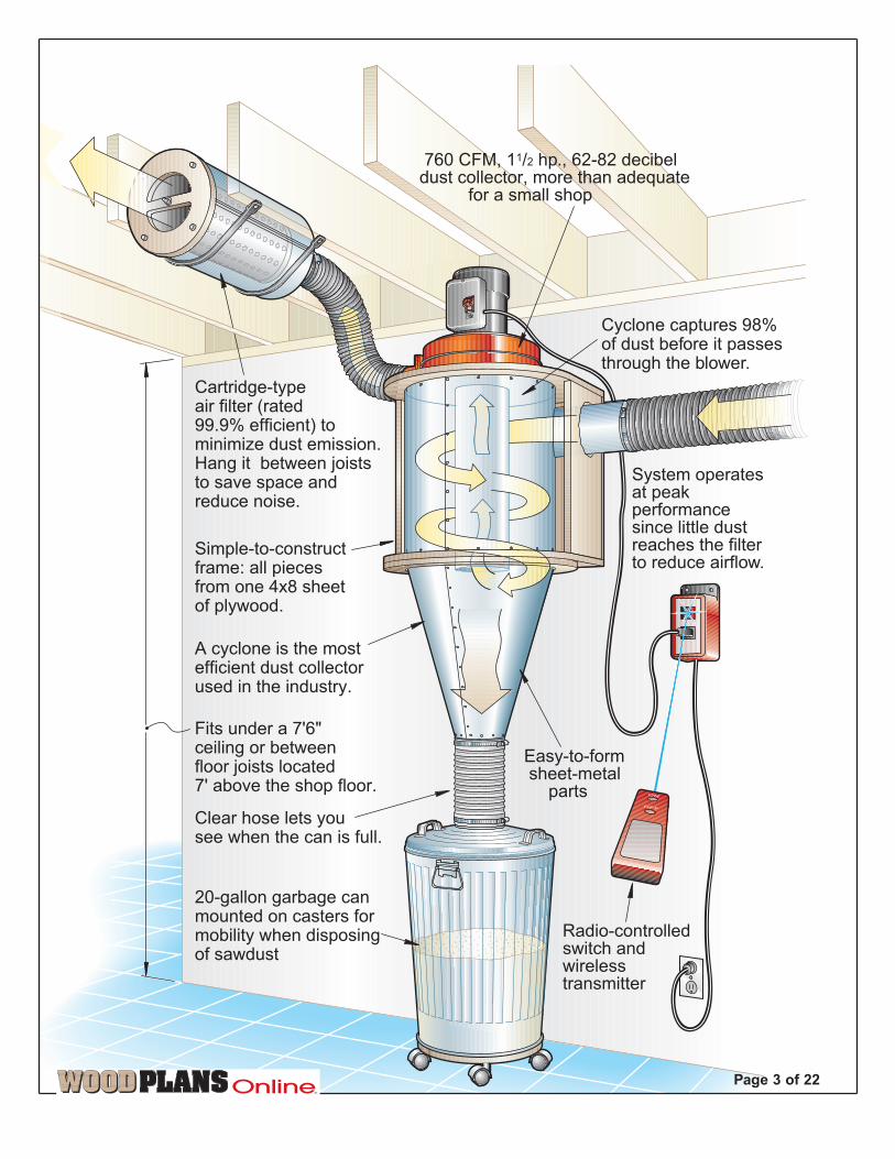
760 CFM, 11/2 hp., 62-82 decibeldust collector, more than adequate for a small shop
Simple-to-constructframe: all piecesfrom one 4x8 sheetof plywood.
Cartridge-typeair filter (rated99.9% efficient) tominimize dust emission.Hang it between joiststo save space andreduce noise.
Easy-to-form sheet-metal parts
Clear hose lets yousee when the can is full.
20-gallon garbage canmounted on casters formobility when disposingof sawdust
Fits under a 7'6"ceiling or betweenfloor joists located7' above the shop floor.
Radio-controlledswitch andwirelesstransmitter
A cyclone is the mostefficient dust collectorused in the industry.
Cyclone captures 98%of dust before it passesthrough the blower.
System operatesat peakperformancesince little dustreaches the filterto reduce airflow.
TM
Page 3 of 22
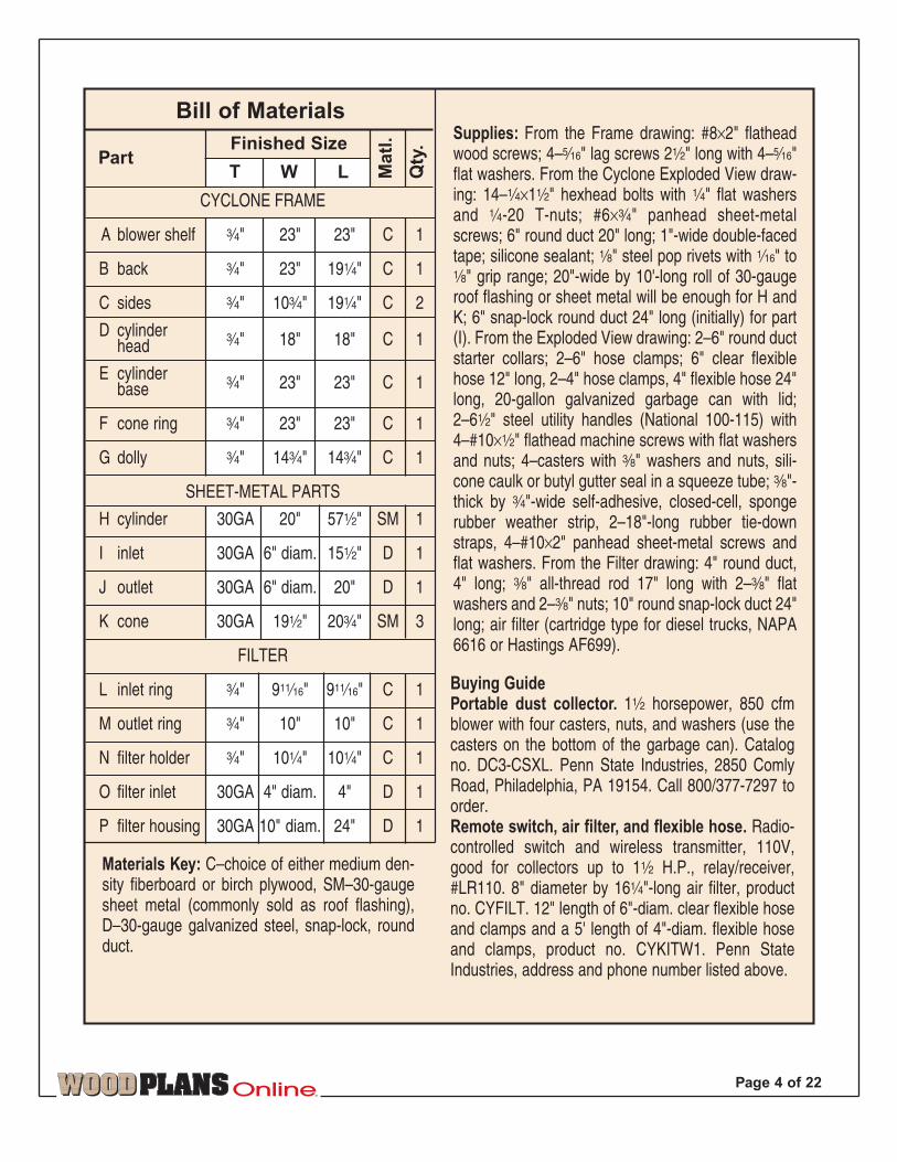
Part
Bill of Materials
Ma
tl.
Qty
.
T W L
Finished Size
CYCLONE FRAME
A blower shelf ‡" 23" 23" C 1
B back ‡" 23" 19‹" C 1
C sides ‡" 10‡" 19‹" C 2
D cylinderhead ‡" 18" 18" C 1
E cylinderbase ‡" 23" 23" C 1
F cone ring ‡" 23" 23" C 1
G dolly ‡" 14‡" 14‡" C 1
SHEET-METAL PARTS
H cylinder 30GA 20" 57fi" SM 1
I inlet 30GA 6" diam. 15fi" D 1
J outlet 30GA 6" diam. 20" D 1
K cone 30GA 19fi" 20‡" SM 3
FILTER
L inlet ring ‡" 9Ø" 9Ø" C 1
M outlet ring ‡" 10" 10" C 1
N filter holder ‡" 10‹" 10‹" C 1
O filter inlet 30GA 4" diam. 4" D 1
P filter housing 30GA 10" diam. 24" D 1
Supplies: From the Frame drawing: #8×2" flatheadwood screws; 4–ˇ" lag screws 2fi" long with 4–ˇ"flat washers. From the Cyclone Exploded View draw-ing: 14–‹×1fi" hexhead bolts with ‹" flat washersand ‹-20 T-nuts; #6ׇ" panhead sheet-metalscrews; 6" round duct 20" long; 1"-wide double-facedtape; silicone sealant; ¤" steel pop rivets with „" to¤" grip range; 20"-wide by 10'-long roll of 30-gaugeroof flashing or sheet metal will be enough for H andK; 6" snap-lock round duct 24" long (initially) for part(I). From the Exploded View drawing: 2–6" round ductstarter collars; 2–6" hose clamps; 6" clear flexiblehose 12" long, 2–4" hose clamps, 4" flexible hose 24"long, 20-gallon galvanized garbage can with lid;2–6fi" steel utility handles (National 100-115) with4–#10×fi" flathead machine screws with flat washersand nuts; 4–casters with ›" washers and nuts, sili-cone caulk or butyl gutter seal in a squeeze tube; ›"-thick by ‡"-wide self-adhesive, closed-cell, spongerubber weather strip, 2–18"-long rubber tie-downstraps, 4–#10×2" panhead sheet-metal screws andflat washers. From the Filter drawing: 4" round duct,4" long; ›" all-thread rod 17" long with 2–›" flatwashers and 2–›" nuts; 10" round snap-lock duct 24"long; air filter (cartridge type for diesel trucks, NAPA6616 or Hastings AF699).
Materials Key: C–choice of either medium den-sity fiberboard or birch plywood, SM–30-gaugesheet metal (commonly sold as roof flashing),D–30-gauge galvanized steel, snap-lock, roundduct.
Buying GuidePortable dust collector. 1fi horsepower, 850 cfmblower with four casters, nuts, and washers (use thecasters on the bottom of the garbage can). Catalogno. DC3-CSXL. Penn State Industries, 2850 ComlyRoad, Philadelphia, PA 19154. Call 800/377-7297 toorder.Remote switch, air filter, and flexible hose. Radio-controlled switch and wireless transmitter, 110V,good for collectors up to 1fi H.P., relay/receiver,#LR110. 8" diameter by 16‹"-long air filter, productno. CYFILT. 12" length of 6"-diam. clear flexible hoseand clamps and a 5' length of 4"-diam. flexible hoseand clamps, product no. CYKITW1. Penn StateIndustries, address and phone number listed above.
TM
Page 4 of 22
B
E
G
A
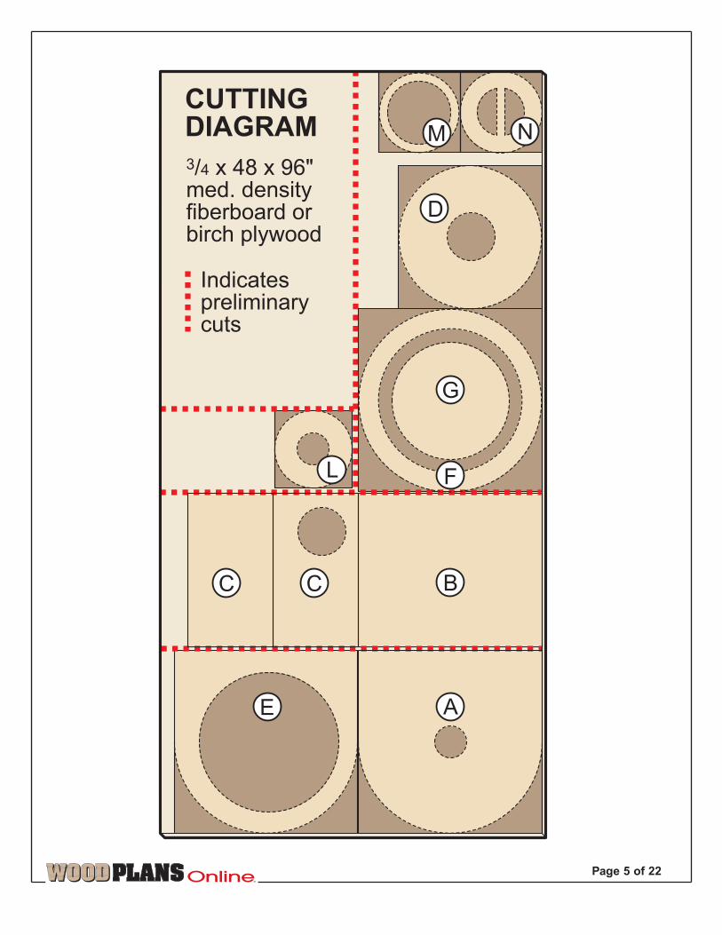
3/4 x 48 x 96"med. densityfiberboard orbirch plywood
CUTTINGDIAGRAM
Indicatespreliminarycuts
C C
L
N
F
M
D
TM
Page 5 of 22
115/16"
5/16"holes
41/8" hole
5/32" holes,countersunk
R=8"
R= 111/2"
115/16"
23"
BLOWER SHELF
23"
R=9"
R=111/2"
R=101/4"
23"
5/32" holes, countersunkon bottom face
5/16" holes
A
101/4"
101/4"
FRAME PARTS VIEW
E
CYLINDERBASE
23"
101/4"
D
G
CONERING
101/4"
R=9"
R=111/2"
R=101/4"
5/16" holes
R=8"
R=9"
115/16"
115/16"
6" hole
5/16" holes
CYLINDERHEAD
43/4"
R=73/8"R=63/4"
3/8" holes
DOLLY(for use under dust bin)
R=31/4"
43/4"
INLETSIDE
C
F
Backedge
6"
TM
Page 6 of 22
R=111/2"R=9"
FRAME
103/4"
5/16" holes
#8 x 2" F.H.wood screws
5/32" shank hole,countersunk
7/64" pilot hole11/4" deep
5/16" flat washer#8 x 2" F.H.wood screw
23"
41/8" hole
61/2" hole
191/4"
191/4"6" hole
#8 x 2" F.H.wood screw
23"
5/16" hole
R=9"
R=9"R=111/2"
5/16" holes
5/32" hole,countersunkon bottom side
5/16" lag screws 21/2" longfor mounting to wall
B
D
E
F
C
A
C
5/16" holes
TM
Page 7 of 22
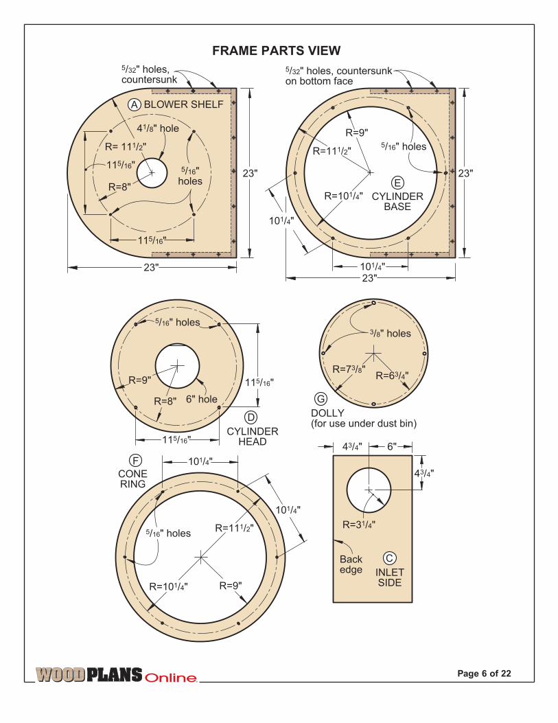
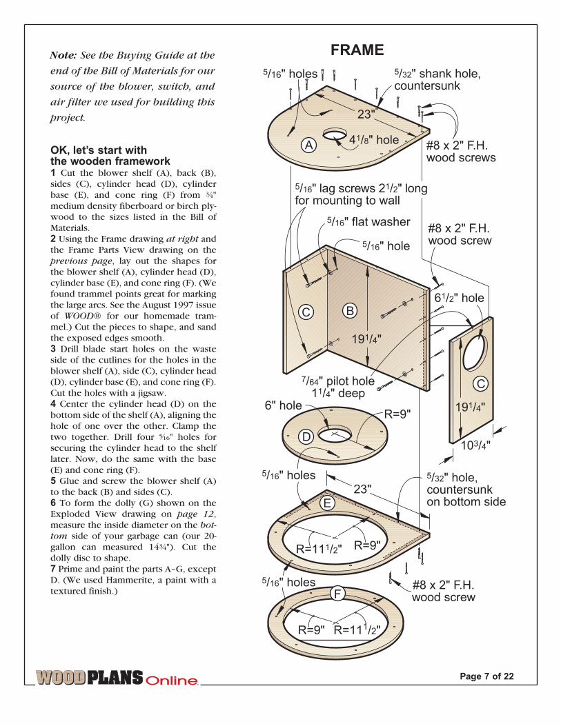
OK, let’s start withthe wooden framework1 Cut the blower shelf (A), back (B),sides (C), cylinder head (D), cylinderbase (E), and cone ring (F) from ‡"medium density fiberboard or birch ply-wood to the sizes listed in the Bill ofMaterials.2 Using the Frame drawing at right andthe Frame Parts View drawing on theprevious page, lay out the shapes forthe blower shelf (A), cylinder head (D),cylinder base (E), and cone ring (F). (Wefound trammel points great for markingthe large arcs. See the August 1997 issueof WOOD® for our homemade tram-mel.) Cut the pieces to shape, and sandthe exposed edges smooth. 3 Drill blade start holes on the wasteside of the cutlines for the holes in theblower shelf (A), side (C), cylinder head(D), cylinder base (E), and cone ring (F).Cut the holes with a jigsaw.4 Center the cylinder head (D) on thebottom side of the shelf (A), aligning thehole of one over the other. Clamp thetwo together. Drill four ˇ" holes forsecuring the cylinder head to the shelflater. Now, do the same with the base(E) and cone ring (F).5 Glue and screw the blower shelf (A)to the back (B) and sides (C).6 To form the dolly (G) shown on theExploded View drawing on page 12,measure the inside diameter on the bot-
tom side of your garbage can (our 20-gallon can measured 14‡"). Cut thedolly disc to shape. 7 Prime and paint the parts A–G, exceptD. (We used Hammerite, a paint with atextured finish.)
Note: See the Buying Guide at the
end of the Bill of Materials for our
source of the blower, switch, and
air filter we used for building this
project.
TM
Page 8 of 22
And now for a little sheet-metal work
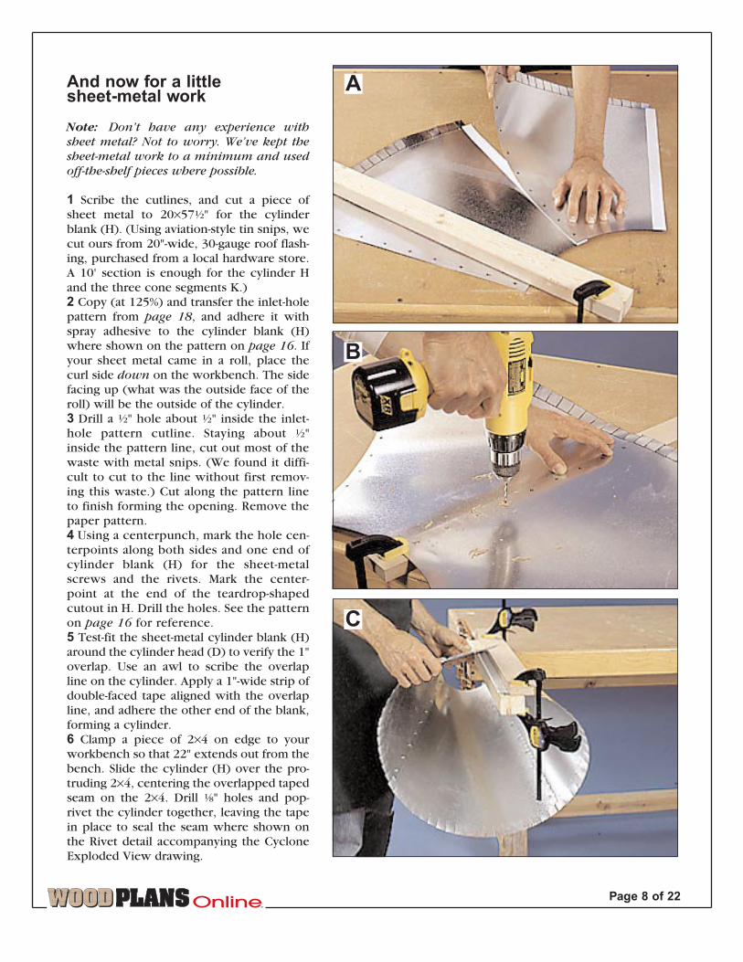
Note: Don’t have any experience withsheet metal? Not to worry. We’ve kept thesheet-metal work to a minimum and usedoff-the-shelf pieces where possible.
1 Scribe the cutlines, and cut a piece ofsheet metal to 20×57fi" for the cylinderblank (H). (Using aviation-style tin snips, wecut ours from 20"-wide, 30-gauge roof flash-ing, purchased from a local hardware store.A 10' section is enough for the cylinder Hand the three cone segments K.) 2 Copy (at 125%) and transfer the inlet-holepattern from page 18, and adhere it withspray adhesive to the cylinder blank (H)where shown on the pattern on page 16. Ifyour sheet metal came in a roll, place thecurl side down on the workbench. The sidefacing up (what was the outside face of theroll) will be the outside of the cylinder.3 Drill a fi" hole about fi" inside the inlet-hole pattern cutline. Staying about fi"inside the pattern line, cut out most of thewaste with metal snips. (We found it diffi-cult to cut to the line without first remov-ing this waste.) Cut along the pattern lineto finish forming the opening. Remove thepaper pattern.4 Using a centerpunch, mark the hole cen-terpoints along both sides and one end ofcylinder blank (H) for the sheet-metalscrews and the rivets. Mark the center-point at the end of the teardrop-shapedcutout in H. Drill the holes. See the patternon page 16 for reference.5 Test-fit the sheet-metal cylinder blank (H)around the cylinder head (D) to verify the 1"overlap. Use an awl to scribe the overlapline on the cylinder. Apply a 1"-wide strip ofdouble-faced tape aligned with the overlapline, and adhere the other end of the blank,forming a cylinder.6 Clamp a piece of 2×4 on edge to yourworkbench so that 22" extends out from thebench. Slide the cylinder (H) over the pro-truding 2×4, centering the overlapped tapedseam on the 2×4. Drill ¤" holes and pop-rivet the cylinder together, leaving the tapein place to seal the seam where shown onthe Rivet detail accompanying the CycloneExploded View drawing.
A
B
C
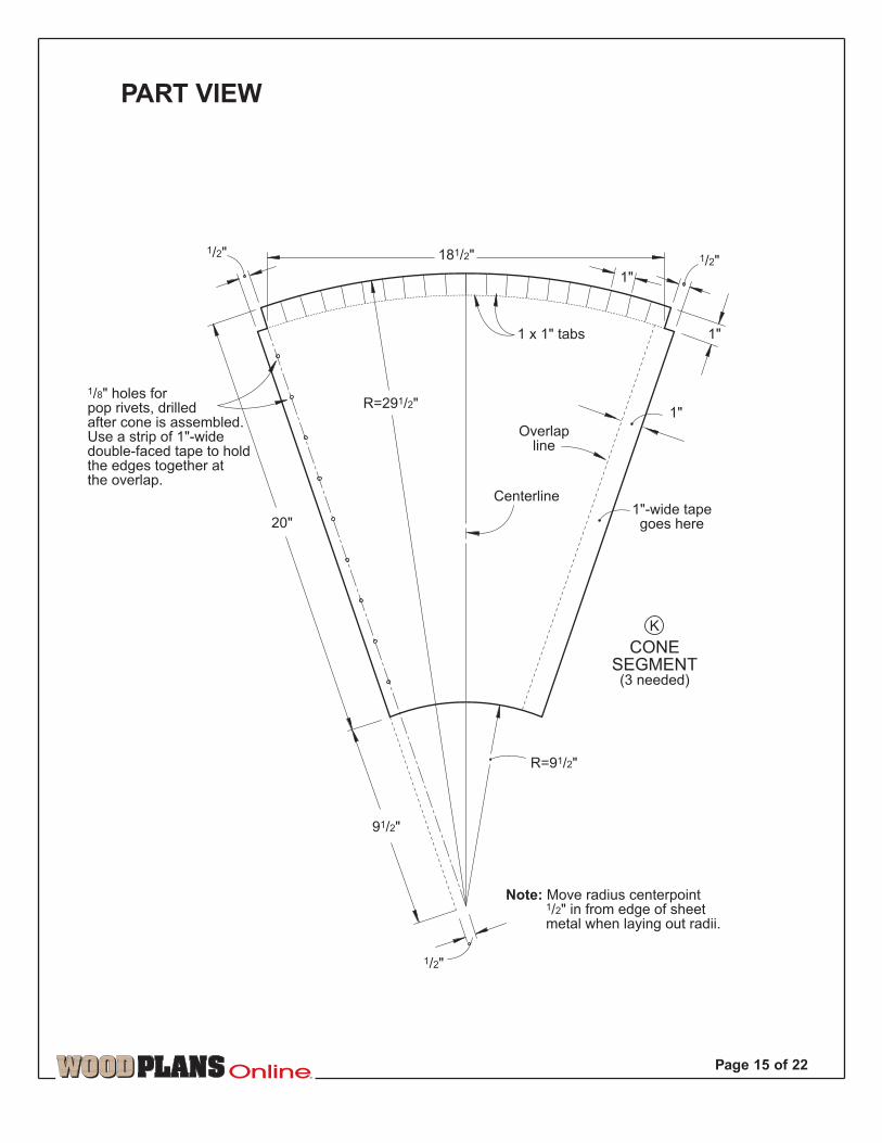
Time to addthe cone1 Lay out thethree cone seg-ments (K) on 30-gauge galvanizedsteel sheet metal.Mark the pop-rivet center-points with apunch. Use anawl to scribe theoverlap lines. Cutthe pieces toshape with thea v i a t i o n - s t y l emetal snips, andcut along thelines to form thetabs at the top ofeach segment.Apply 1"-widestrips of double-
faced tape, aligned with thescribed overlap lines. Stick thefirst two segments together asshown in Photo A on page 8.2 As shown in Photo B, drill ¤"holes at the marked centerpoints.Pop-rivet this first joint to join thefirst two cone segments. Repeatthis process to fasten the thirdsegment to the first two.3 Clamp the 2×4 flat on the work-bench as shown in Photo C.Clamp the taped edge of the threejoined cone segments to the 2×4using another board aligned withthe overlap line to hold it flat.Using the clamping board as aguide, adhere the free end of thejoined cone segments to the tape,forming a cone (K) as shown inPhoto C. Drill ¤" holes at themarked centerpoints, unclampthe cone, and pop-rivet the over-lapping edges together.
Add the starter collarand cone ring to the cone1 Reclamp the 2×4 on edge to theworkbench. Mark the location ofevery other tab of the 6" startercollar around the outside of thebottom opening of the cone.Insert the tabs of the starter collar
into the cone, and slide the coneand starter collar over the 2×4.Drill through the cone and thetabs as shown in Photo D. Pop-rivet the collar into place.2 Support the edge of your conering (F) on the edge of your work-bench as shown in Photo E. Dropthe completed cone (K) into thering and bend down the tabs asshown in the photo.3 Place the cone on the work-bench with the tabs down. Clampthe cone ring down tightly. Cleanthe metal with denatured alcohol,and apply sealant to the jointbetween the cone and the startercollar and in the gap between thecone and the cone ring whereshown on the Cylinder Base detailon the next page.
It’s time to connectthe inlet and outlet1 Position the inlet (I) in the tear-drop-shaped cutout in the cylin-der (H) so the ends of the tab cuts
are flush with the surface of thecylinder. Align the rivet hole atthe end of the teardrop-shapedcutout in the cylinder with therivet hole at the pointed end ofthe inlet. Pop-rivet them together.2 Bend the tabs on the inlet (I)over so they are flat on the inside
of the cylinder (H). Now, drillingfrom the inside and riveting fromthe outside, drill through everyother tab and through the cylin-der. Pop-rivet the inlet to thecylinder, checking to make surethat the inlet remains properlyaligned in the hole in cylinder (H).3 Cut the outlet (J) from a piece of6" round duct, cutting off thecrimped end. Do not snap theduct together until the outlet hasbeen cut. Snap the seam together,and insert the outlet into the holein the center of the cylinder head(D). Make certain the top edge ofthe outlet is flush with the top sur-face of the cylinder head. Drill thepilot holes, and screw the outletto the cylinder head. See the Shelfdetail for reference.
TM
Page 9 of 22
7 Use a hammer and block ofwood to seat the T-nuts in the ˇ"holes in the cylinder head (D). Fitthe cylinder head into the top ofthe cylinder (H). Drill pilot holesthrough the cylinder and into theedge of the cylinder head. Drivethe screws to connect the two,making certain the top surface ofthe cylinder head is flush with thetop edge of the metal cylinder.8 Copy (at 200%) the pattern forthe inlet (I) from the Full-Size Half-Patterns (You will need to maketwo copies and cut one out andthen reverse it to get the wholepattern), and adhere it with sprayadhesive to a piece of 6"-diametersnap-lock round duct 24" long. Donot snap the duct together untilthe end of the inlet has been cut.Align the straight end of the paperpattern with the uncrimped endof the duct. Using metal snips, cutalong the curved pattern lines,and then make the cuts to formthe tabs at the same end. 9 Drill the ¤" rivet holes in theend of the inlet and in every othertab where marked. Now, removethe paper pattern, and snap theseam together.
D
E
CYLINDERBASE DETAILSECTION VIEW
RIVET DETAIL
5/16" hole
1/4" T-nut
6" hole
#6 x 3/4" panheadsheet-metal screw
6"-diametersnap-lockround duct20" long
1/8" holes#6 x 3/4" panheadsheet-metal
screw 6"-diameter snap-lockround duct inlet
151/2" long(See the pattern insertfor full-sized pattern.)
Cylinder 20 x 571/2" sheet metal
1/4 x 11/2" hexhead bolt
Bottom of fits inside18"-diameter hole in .
Silicone sealant
CONE
CYLINDER
#6 x 3/4" panheadsheet-metal screw
SHELF DETAILSECTION VIEW
Silicone sealant
#6 x 3/4" panheadsheet-metal screws
CYLINDER
6" duct 20" long
CYCLONEEXPLODED
VIEW
1" overlap
1"-widedouble-faced tape
1/8" holes, drilled at the same
time
1/8" steel pop rivet,1/16 -1/8" grip range
Sheet metal
1" tabs bent overinside of cylinderand pop-rivetedafter duct is insertedthrough opening
Duct openingcut into cylinder
20"
5/16" hole
1/4 x 11/2"hexhead bolt
1/4" flat washer
5/16" hole
1/4" flat washer
5/16" hole
1/4" T-nut
Cone(sheet metal)
#8 x 2" F.H.wood screws
6" starter collar(tabs are pop-riveted tobottom inside face of cone)
1" tabs bent over conering and sandwichedbetween and
J
D
E
E
C
F
A
C
D
J
H
I
H
H
C
A
B
C
F
E
K
K K
FEF
H
H
K
H
Secure frameto wall withlag screws.
H
TM
Page 10 of 22
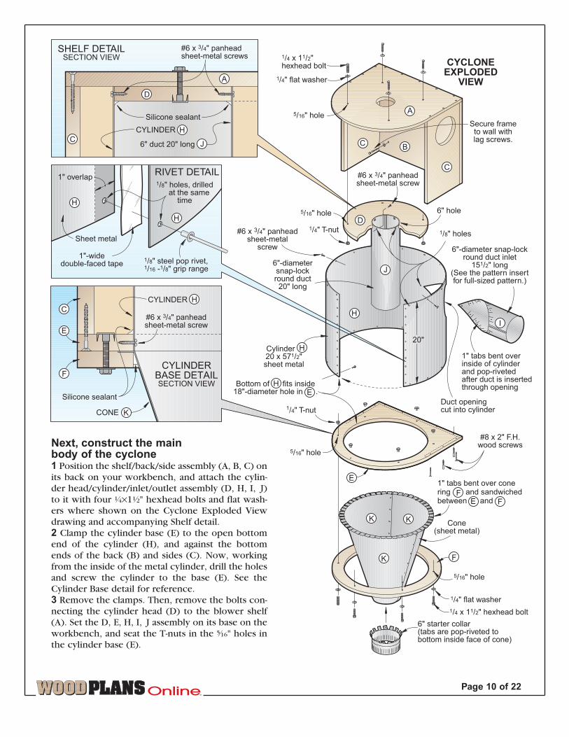
Next, construct the main body of the cyclone1 Position the shelf/back/side assembly (A, B, C) on
its back on your workbench, and attach the cylin-
der head/cylinder/inlet/outlet assembly (D, H, I, J)
to it with four ‹×1fi" hexhead bolts and flat wash-
ers where shown on the Cyclone Exploded View
drawing and accompanying Shelf detail.
2 Clamp the cylinder base (E) to the open bottom
end of the cylinder (H), and against the bottom
ends of the back (B) and sides (C). Now, working
from the inside of the metal cylinder, drill the holes
and screw the cylinder to the base (E). See the
Cylinder Base detail for reference.
3 Remove the clamps. Then, remove the bolts con-
necting the cylinder head (D) to the blower shelf
(A). Set the D, E, H, I, J assembly on its base on the
workbench, and seat the T-nuts in the ˇ" holes in
the cylinder base (E).
the bottom side of the garbagecan. Drill four ›" holes throughthe dolly and through the bottomof the garbage can. (The four cast-ers and mating hardware comewith the blower sourced in theBuying Guide.) Secure the castersto the dolly and garbage can. Putthe lid on the can and roll it aside.
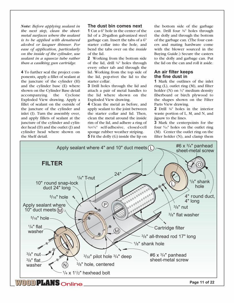
An air filter keeps the fine dust in1 Mark the outlines of the inletring (L), outlet ring (M), and filterholder (N) on ‡" medium densityfiberboard or birch plywood tothe shapes shown on the FilterParts View drawing. 2 Drill ›" holes in the interiorwaste portion of L, M, and N, andjigsaw to the lines.3 Mark the centerpoints for thefour ˇ" holes on the outlet ring(M). Center the outlet ring on thefilter holder (N), and clamp them
The dust bin comes next1 Cut a 6" hole in the center of thelid of a 20-gallon galvanized steelgarbage can. Insert the tabs of a 6"starter collar into the hole, andbend the tabs over on the inside
of the lid.2 Working from the bottom sideof the lid, drill ¤" holes throughevery other tab and through thelid. Working from the top side ofthe lid, pop-rivet the lid to thestarter collar.3 Drill holes through the lid andattach a pair of metal handles tothe lid where shown on theExploded View drawing.4 Clean the metal as before, andapply sealant to the joint betweenthe starter collar and lid. Then,clean the metal around the insiderim of the lid, and adhere a ring of›×‡" self-adhesive, closed-cellsponge rubber weather striping.5 Fit the dolly (G) inside the lip on
Note: Before applying sealant in
the next step, clean the sheet-
metal surfaces where the sealant
is to be applied with denatured
alcohol or lacquer thinner. For
ease of application, particularly
on the inside of the cylinder, use
sealant in a squeeze tube rather
than a caulking gun cartridge.
4 To further seal the project com-ponents, apply a fillet of sealant atthe juncture of the cylinder (H)and the cylinder base (E) whereshown on the Cylinder Base detailaccompanying the CycloneExploded View drawing. Apply afillet of sealant on the outside ofthe juncture of the cylinder andinlet (I). Turn the assembly over,and apply fillets of sealant at thejuncture of the cylinder and cylin-der head (D) and the outlet (J) andcylinder head where shown onthe Shelf detail.
24"
10" round snap-lockduct 24" long
Cartridge filter
3/8" nut
3/8" flat washer
3/8" all-thread rod 17" long
Apply sealant where 4" and 10" duct meets .
4" round duct,4" long
#6 x 3/4" panheadsheet-metal screw
#6 x 3/4" panheadsheet-metal screw
1/4" T-nut
3/32" pilot hole 3/4" deep
1/8" shank hole
5/16" hole
5/16" hole
1/4 x 11/2" hexhead bolt
1/4" flatwasher
3/8" hole, centered
1/8" shankhole
3/8" nut3/8" flatwasher
FILTER
L
N
L
Apply sealant where 10" duct meets .M
O
P
M
TM
Page 11 of 22

Self-adhesiveweather strip(adhere toundersideof lid)
G
H
K
L
N
C
A
FILTER
4" hose clamps
4" flexible hose,cut to required length
18" rubber tie-downwith hooks removed
#10 x 2" panheadsheet-meal screw,screwed into floorjoist to hold filterin place
#10 flat washer
Self-adhesiveweather strip
(adhere to blower)
BLOWER
6" hose clamps
6" clear flexiblehose 12" long
CONE
6" startercollar (tabsare bent andpop-rivetedto insideof garbagecan lid)
61/2" utility handle
3/16" hole
#10 flat washer
#10 x 1/2" F.H.machine screw
#10 nut
20-gallongalvanizedgarbage can
Garbagecan lid
3/8" holes throughdolly andbottom ofgarbage can
Casters
3/8" nut
3/8" washer
6" starter collar
EXPLODEDVIEW
FILTER HOLDER
OUTLET RING
R=5"R=41/2"
5/16" holes
65/16"
R=3"
3/8" holein corners
3/8"
R=41/2"
R=51/8"
3/8" hole
INLET RING
R=2"R=427/32"
4" hole
FILTER PARTS VIEW
O
P
M
65/16"
5/16" holes
65/16"
65/16"
B
I
E
F
G
INLETCYLINDER
6"-dia. hole
N
R=41/8"
Note: Caulkany seamsor holeswhere airmight leak in.
together. Drill the ˇ" holesthrough both pieces. Unclampthe pieces, and drill a ›" holethrough the center of N.4 Finish-sand the pieces, andpaint parts L and N.5 Cut a piece of 4" snap-lockduct for the filter inlet (O) to 4"long, snap it together, and insertit into the hole in the inlet ring(L). Drill the pilot holes andscrew the pieces together.6 Seat the T-nuts in the ˇ"holes in the outlet ring (M).Snap a 24"-long section of 10"snap-lock duct together to formpart (P). Fit the inlet ring (L) into the crimped end where shownon the Filter drawing. Drill pilot holes, and screw the duct to theinlet ring.7 Fit the outlet ring (M) into the uncrimped end of P. Drill thepilot holes, and drive in the screws. 8 Clean the metal, and apply sealant around the inside of the fil-ter housing (P) where the duct meets the inlet and outlet ringsand where the inlet (O) meets the inlet ring.9 Fasten the cartridge filter to the filter holder (N) with a 17"-long piece of ›" all-thread rod, washers, and nuts, making cer-tain the cartridge is centered on the filter holder. Slide the car-tridge/filter holder assembly into the filter housing, and fasten itinto place.Note: See page 14 for a quick and quiet improvement you can
add to the filter.
Final assembly1 Drill holes through the back (B) for mounting the unit to thewall later. See the Frame drawing for reference. Position theholes so you hit at least one stud (and ideally two) in the wall.Fasten the bracket assembly (A, B, C) to the wall so that the topof the blower shelf (A) is level and 76" from the floor. The totalheight required for the dust collector is 90". If there is not suffi-cient clearance underneath the floor joists, position the assem-bly (A, B, C) so that the blower motor will be located betweentwo floor joists. Allow for a minimum clearance of 1" over thetop of the blower motor.2 Fit the cylinder assembly (D, E, H, I, J) into the bracket assem-bly by rotating it enough to fit the inlet (I) through the hole inthe side (C), and fasten it in place with ‹" bolts. Then, securethe cylinder base (E) to the back (B) and the sides (C) with 2"wood screws.3 Position the cone assembly (F, K) underneath the cylinderbase (E), and fasten it in place with ‹" bolts, sandwiching the 1"tabs of the cone (K) between the cylinder base and the conering (F) where shown on the Cyclone Exploded View drawing.4 Attach a 12" length of 6" flexible hose to the starter collar atthe bottom of the cone with a hose clamp. Position the dust bin
TM
Page 12 of 22

Sw
o
L
N FILTER HOLDER
OUTLET RING
R=5"R=41/2"
5/16" holes
65/16"
R=3"
3/8" holein corners
3/8"
R=41/2"
R=51/8"
3/8" hole
INLET RING
R=2"R=427/32"
4" hole
FILTER PARTS VIEW
M
65/16"
5/16" holes
65/16"
65/16"
6
R=41/8"
aow
TM
Page 13 of 22
under the cone, and attach the other end of the hose tothe starter collar on the can lid with a hose clamp whereshown on the Exploded View drawing.5 Adhere a piece of ›×‡" weather stripping to form aring approximately 11" in diameter to the intake (bottom)side of the blower. Seal any unused bolt holes in theblower. (The blower comes mounted to a frame.) Set theblower in place on the blower shelf (A) with its intakeflange inserted into the 4¤"-diameter hole. Hang the filterassembly (L, M, N, O, P) between two conveniently locat-ed floor joists, using a pair of rubber tie-down strapswhere shown on the Exploded View drawing. Connectthe blower to the filter with a length of 4" flexible hoseand two hose clamps.6 Hook up the dust-collection piping to the inlet (I). 7 For convenience, we plugged the blower into a radiofrequency controlled switch so we can operate it fromany location in the shop with a wireless transmitter.8 Periodically you’ll need to remove the filter and blow itout. Also, by watching the clear hose above the garbagecan, you’ll be able to tell when the can is full.¿
Written by Marlen Kemmet
Project Design: Jan Hale Svec
Illustrations: Kim Downing; Lorna Johnson
Graphic Design: Lorna Johnson
Photographs: John Hetherington; Bill Hopkins
©Copyright Meredith Corporation 1998
The purchase of these plans does
not transfer any copyright or other
ownership interest in the plans, the
design, or the finished project to the
buyer. Buyer may neither reproduce
the plans for sale nor offer for sale
any copies of the finished project.
TM
Page 14 of 22
2"-thick6"-dia. foam
24"
#6 x 3/4" panheadsheet-metal screw
1/8" shankhole
10"-round snap-lockduct 24" long
#6 x 3/4" panheadsheet-metal screw
3/32" pilot hole 3/4" deep
4" hose clamp
CYCLONEDUST COLLECTOR
MUFFLER
FILTER
4" flexible hose
911/16"-dia.3/4" plywood disc
4" startercollar
Pop-rivet tabsto inside ofhole, then applysilicone sealant tothe outside seam.
4"-dia. hole
6"-dia. hole
2 x 201/2 x 317/16" foam
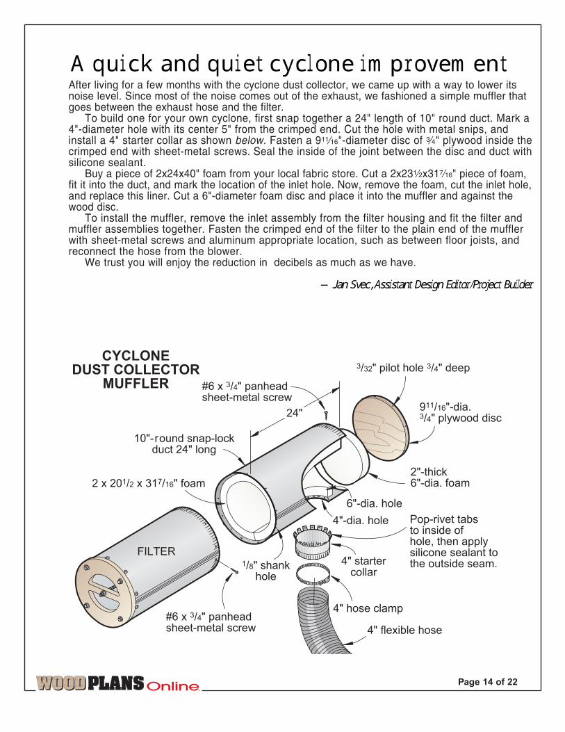
A quick and quiet cyclone improvementAfter living for a few months with the cyclone dust collector, we came up with a way to lower itsnoise level. Since most of the noise comes out of the exhaust, we fashioned a simple muffler thatgoes between the exhaust hose and the filter.
To build one for your own cyclone, first snap together a 24" length of 10" round duct. Mark a4"-diameter hole with its center 5" from the crimped end. Cut the hole with metal snips, andinstall a 4" starter collar as shown below. Fasten a 9Ø"-diameter disc of ‡" plywood inside thecrimped end with sheet-metal screws. Seal the inside of the joint between the disc and duct withsilicone sealant.
Buy a piece of 2x24x40" foam from your local fabric store. Cut a 2x23fix31Á" piece of foam,fit it into the duct, and mark the location of the inlet hole. Now, remove the foam, cut the inlet hole,and replace this liner. Cut a 6"-diameter foam disc and place it into the muffler and against thewood disc.
To install the muffler, remove the inlet assembly from the filter housing and fit the filter andmuffler assemblies together. Fasten the crimped end of the filter to the plain end of the mufflerwith sheet-metal screws and aluminum appropriate location, such as between floor joists, andreconnect the hose from the blower.
We trust you will enjoy the reduction in decibels as much as we have.
—Jan Svec, Assistant Design Editor/Project Builder
TM
Page 15 of 22
1/8" holes forpop rivets, drilledafter cone is assembled.Use a strip of 1"-widedouble-faced tape to holdthe edges together atthe overlap.
Centerline
20"
Overlapline
CONESEGMENT(3 needed)
K
1"
181/2"
1 x 1" tabs
1"
1"
R=91/2"
1/2"
1/2"
Note: Move radius centerpoint1/2" in from edge of sheet
metal when laying out radii.
91/2"
R=291/2"
1/2"
1"-wide tapegoes here
PART VIEW

H
Inlet hole 43/4"
1/8" holes for pop rivets, drilledafter cylinder is formed. Use a1"-wide strip of double-faced
tape to hold the ends togetherat the overlap.
Overlapline
Mark locationsfor #6 panhead
sheet-metal screws.
1"
20"
CYLINDER
3/8"
1"
1/8" hole drilledbefore assembly
3/8"
1/2"
4"
11/2" 283/4"
571/2"
4" 4"
30-gaugegalvanized-steel
sheet metal
Drill rivet holesfor the inlet
after has been placed through the inlet hole.
II
57
1/2"
20"
K
K
K
CO
NE
SE
GM
EN
TC
UT
TIN
GD
IAG
RA
M30
-gauge
ga
lvaniz
ed-s
teel
sh
eet m
eta
l
TM
Pag
e 1
6 o
f 22
PA
RT
SV
IEW
TM
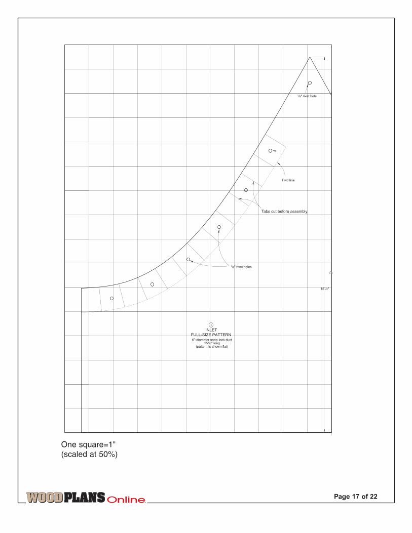
Page 17 of 22
151/2"
1/8" rivet holes
1/8" rivet hole
6"-diameter snap-lock duct151/2" long
(pattern is shown flat)
I
INLET
Fold line
FULL-SIZE PATTERN
Tabs cut before assembly.
One square=1"
(scaled at 50%)
TM
Pag
e 1
8 o
f 22
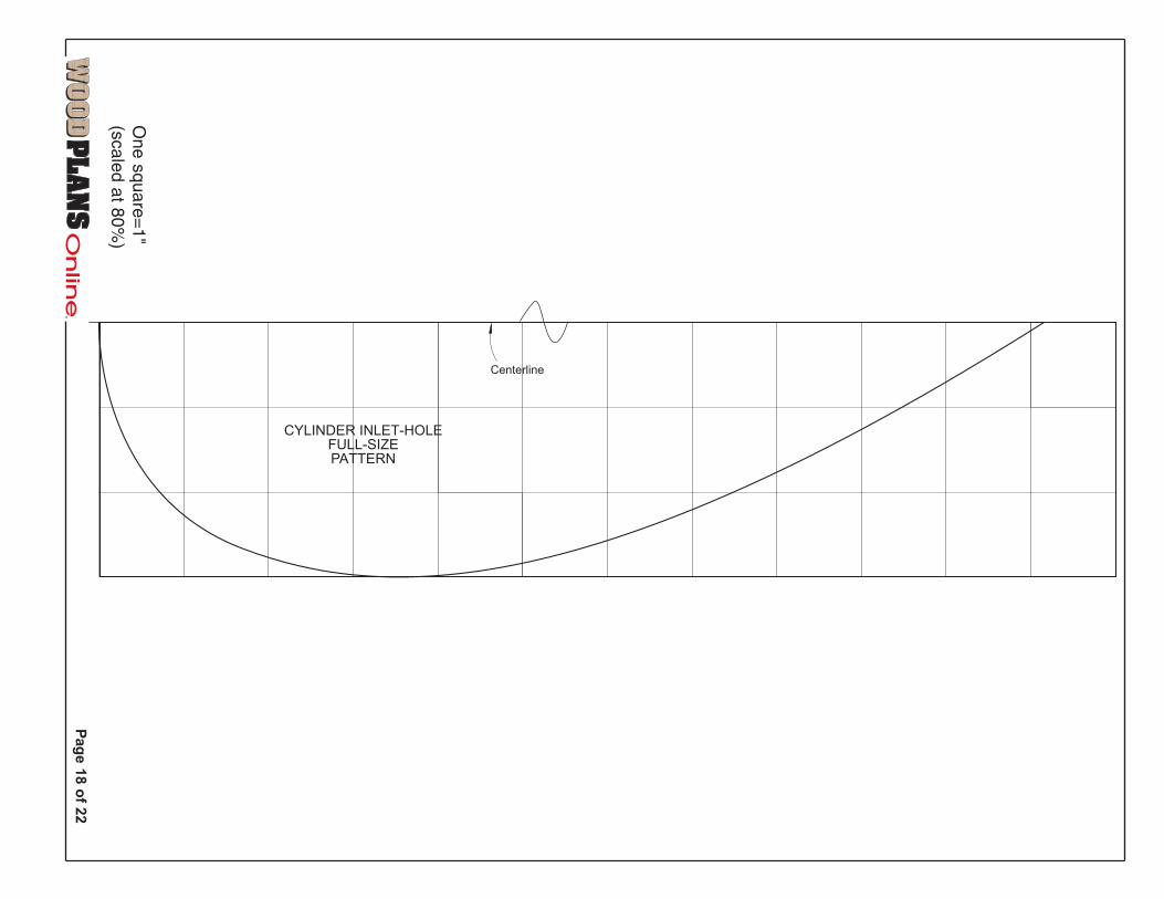
Centerline
CYLINDER INLET-HOLEFULL-SIZEPATTERN
One s
quare
=1"
(scale
d a
t 80%
)

TM
Page 19 of 22
I downloaded the plans for the
cyclone dust collector from your Web
site, and built it pretty much as
shown. My only departures were a
2-hp blower and felt filter bags.
At the end of a 4' length of duct
connected to the cyclone’s inlet, I
measured an air flow of 350 cfm.
After installing a “neutral vane”
inside the cyclone, shown on
Drawing 1, the flow increased to
525 cfm. This is a significant
increase in performance for such
a simple modification, and is well
worth trying out.
—John Dillbeck, Shell Knob, Mo.
Another reader recently called us for advice on building the cyclone, and described
the same sort of deflector inside an old cyclone that was once part of a piece of farm
machinery. Perhaps they knew something we didn’t when we designed our cyclone.
It wouldn’t be too difficult to retrofit an existing cyclone in this manner. But better
yet, incorporating a similar detail in a new cyclone would simplify its construction.
When forming the teardrop-shape cutout in the cyclone’s cylinder (H), leave three
tabs around its perimeter, where shown on Drawing 2. Bend the tabs into the cylin-
der, and trim the end of the inlet duct (I) at an
angle so it clears the outlet duct. Insert the inlet
and pop-rivet the tabs to it, where shown on
Drawing 3. Seal around the inlet/cylinder joint on
the outside with caulk.
Our bulletin board for letters, comments, and timely updatestalking back
H
43/4"
Leave 1" tabs to attach part .I
2 CYLINDER—NEW OPTION
Increase the performance of your cyclone
H
I
5"
Riveting tabs
Location of
Neutralvane
D
5"I
Part cut at aslight angle
I
H
Riveting tabs on part H
DLocation of
1 MODIFICATION
3 INLET—NEW OPTION

I must say that your homemade “Cyclone” certainly encompasses all one’s needs in a basement-type dust collector. It’s compact, quiet, inexpensive, and fairly easy to make. Congratulations to MrSvec and all who helped to bring his creation to life.
However, I noticed that you use a clear, flexible hose to attach the bottom of the Cyclone to thegarbage can that “lets you see when the can is full.” Trouble is, the can would then be overfull.
Instead, I suggest cutting out a narrow vertical opening (one inch) in the side of the garbagecan, beginning about 3" from the top of the can, and ending about 3" from the bottom. Then, usingconstruction adhesive, attach a strip of clear plastic to the inside of the can, overlapping the cut-out section as shown below. This strip must be sealed air tight. Now you have a window that letsyou see how full the can really is.
—Rich Lacey, Willowick, Ohio
TM
Page 20 of 22
3"
3"
1"
Clearplasticstripglued toinside ofgarbagecan
1" cutout
How to know when you’re almost full
TM
Page 21of 22
Cyclone off
Clean filtermark
Time to clean
Open end
1/2"
Strap
Mounting board
3"
14"
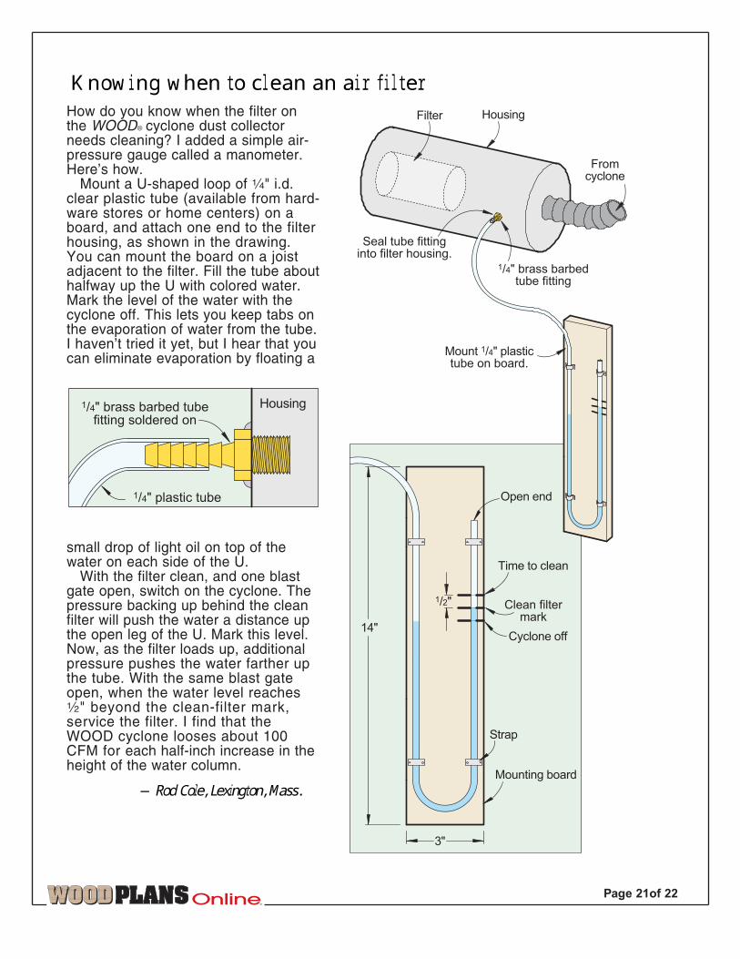
How do you know when the filter onthe WOOD® cyclone dust collectorneeds cleaning? I added a simple air-pressure gauge called a manometer.Here’s how.
Mount a U-shaped loop of ‹" i.d.clear plastic tube (available from hard-ware stores or home centers) on aboard, and attach one end to the filterhousing, as shown in the drawing.You can mount the board on a joistadjacent to the filter. Fill the tube abouthalfway up the U with colored water.Mark the level of the water with thecyclone off. This lets you keep tabs onthe evaporation of water from the tube.I haven’t tried it yet, but I hear that youcan eliminate evaporation by floating a
small drop of light oil on top of thewater on each side of the U.
With the filter clean, and one blastgate open, switch on the cyclone. Thepressure backing up behind the cleanfilter will push the water a distance upthe open leg of the U. Mark this level.Now, as the filter loads up, additionalpressure pushes the water farther upthe tube. With the same blast gateopen, when the water level reachesfi" beyond the clean-filter mark,service the filter. I find that theWOOD cyclone looses about 100CFM for each half-inch increase in theheight of the water column.
—Rod Cole, Lexington, Mass.
Housing1/4" brass barbed tubefitting soldered on
1/4" plastic tube
Knowing when to clean an air filter
Mount 1/4" plastictube on board.
Seal tube fittinginto filter housing.
Filter Housing
Fromcyclone
1/4" brass barbedtube fitting

TM
Page 22 of 22
Shop Vacuum
Exhaust Intake
AIR FLOW
CYCLONE DUST FILTERCLEANER
Cyclone dust filterdisconnected from cyclone
Wrap self-adhesive foam weatherstrip around duct to sealconnection if necessary.
6" to 4" ductadapter
4" to 21/2" plastichose adapter
Notch both sides ofadapter to fit intoend of air filter.
4" to 21/2" plastichose adapter
Hole in end of filter is 6"
Shop Vacuum
Back-flashCyclone, tooThanks for the great CycloneDust Collector project. Yourchoice of a NAPA air filter wasexcellent. I have been using thisset-up to back-flush it andextend its life: I disconnectedthe filter and installed severaladapters so that I can connectinlet and outlet hoses of myshop vacuum. The closed-loopsystem effectively cleans thefilter without disassembly and adusty mess.
—Ken Gossafe, Bellevue, Wash.
D
A
Make existing6" duct 8"shorter fornew reducer.
Add 6x4"reducerhere.
Cut holes in top of(A) and (D) 4" indiameter insteadof 6" as showon plan.
Blower/Motor
BPop rivet ductand reducertogether.
8"
F
E
Siliconesealant
SECTION VIEWOF CYCLONE
QUICK FIXINCREASES SUCTION
Seal jointwithsiliconeto preventleakage.
Cylinder H
Gain static pressurewith reducerCongratulations on your CycloneDust Collector design. I built thecollector and was impressed withthe clear instructions. As a retiredmechanical engineer, I do haveone suggestion. I calculated thestatic pressure (S.P.) in order tosize the ductwork, and discov-ered a drop of .85" S.P. at theabrupt exit from the collector tothe fan inlet. By installing a 6×4"reducer fitting before exiting thedust collector, I saved approxi-mately .72" S.P.
—Albert J. Cappelloni, Scranton, Pa.


![Cyclone Handbook, Section I. Cyclone FPGA Family Data Sheet1]EP1C12F256C8.pdf · Section I. Cyclone FPGA Family Data Sheet ... Cyclone Device Handbook, ... Vertical migration means](https://img.dokumen.tips/doc/110x75/5b3a24897f8b9a600a8f2cfc/cyclone-handbook-section-i-cyclone-fpga-family-data-sheet-1ep1c12f256c8pdf.jpg)