Embed Size (px)
DESCRIPTION
The Hubbell Building Automation CX Commercial Lighting Control Panels provide feature rich and cost effective lighting control for maximum energy savings utilizing both switching and 0-10V dimming.
Citation preview

hubbell-automation.com

2
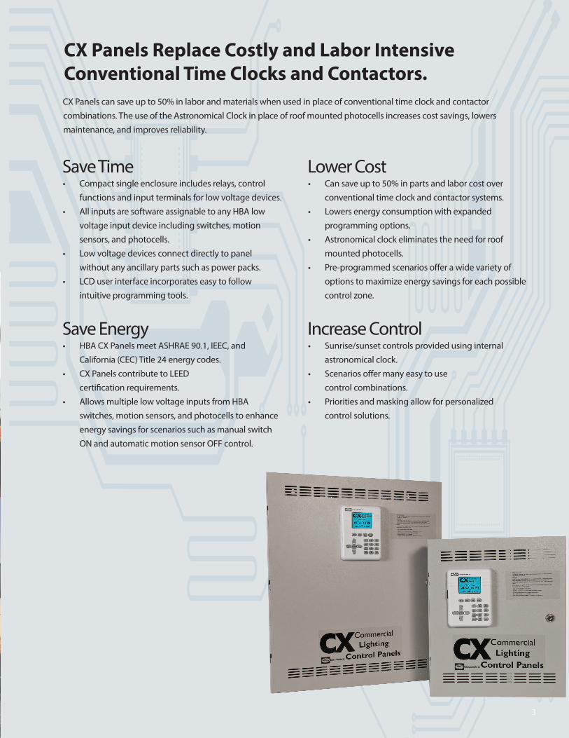
CX Panels can save up to 50% in labor and materials when used in place of conventional time clock and contactor combinations. The use of the Astronomical Clock in place of roof mounted photocells increases cost savings, lowers maintenance, and improves reliability.
Save Time• Compact single enclosure includes relays, control
functions and input terminals for low voltage devices.• All inputs are software assignable to any HBA low
voltage input device including switches, motion sensors, and photocells.
• Low voltage devices connect directly to panel without any ancillary parts such as power packs.
• LCD user interface incorporates easy to follow intuitive programming tools.
Save Energy• HBA CX Panels meet ASHRAE 90.1, IEEC, and
California (CEC) Title 24 energy codes.• CX Panels contribute to LEED
certification requirements.• Allows multiple low voltage inputs from HBA
switches, motion sensors, and photocells to enhance energy savings for scenarios such as manual switch ON and automatic motion sensor OFF control.
Lower Cost• Can save up to 50% in parts and labor cost over
conventional time clock and contactor systems.• Lowers energy consumption with expanded
programming options.• Astronomical clock eliminates the need for roof
mounted photocells.• Pre-programmed scenarios offer a wide variety of
options to maximize energy savings for each possible control zone.
Increase Control• Sunrise/sunset controls provided using internal
astronomical clock.• Scenarios offer many easy to use
control combinations.• Priorities and masking allow for personalized
control solutions.
CX Panels Replace Costly and Labor Intensive Conventional Time Clocks and Contactors.
3
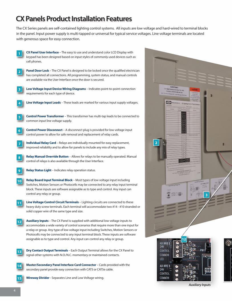
The CX Series panels are self-contained lighting control systems. All inputs are low voltage and hard-wired to terminal blocks in the panel. Input power supply is multi-tapped or universal for typical service voltages. Line voltage terminals are located with generous space for easy connection.
Auxiliary Inputs Dry Contact Outputs
CX Panel User Interface – The easy to use and understand color LCD Display with keypad has been designed based on input styles of commonly used devices such as cell phones.
Panel Door Lock – The CX Panel is designed to be locked once the qualified electrician has completed all connections. All programming, system status, and manual controls are available via the User Interface once the door is secured.
Low Voltage Input Device Wiring Diagrams – Indicates point-to-point connection requirements for each type of device.
Line Voltage Input Leads – These leads are marked for various input supply voltages.
Control Power Transformer – This transformer has multi-tap leads to be connected to common input line voltage supply.
Control Power Disconnect – A disconnect plug is provided for low voltage input control power to allow for safe removal and replacement of relay cards.
Individual Relay Card – Relays are individually mounted for easy replacement, improved reliability and to allow for panels to include any mix of relay types.
Relay Manual Override Button – Allows for relays to be manually operated. Manual control of relays is also available through the User Interface.
Relay Status Light – Indicates relay operation status.
Relay Board Input Terminal Block – Most types of low voltage input including Switches, Motion Sensors or Photocells may be connected to any relay input terminal block. These inputs are software assignable as to type and control. Any input can control any relay or group.
Line Voltage Control Circuit Terminals – Lighting circuits are connected to these heavy duty screw terminals. Each terminal will accommodate two #14 - #10 stranded or solid copper wire of the same type and size.
Auxiliary Inputs – The CX Panel is supplied with additional low voltage inputs to accommodate a wide variety of control scenarios that require more than one input for a relay or group. Any type of low voltage input including Switches, Motion Sensors or Photocells may be connected to any input terminal block. These inputs are software assignable as to type and control. Any input can control any relay or group.
Dry Contact Output Terminals – Each Output Terminal allows for the CX Panel to signal other systems with N.O./N.C. momentary or maintained contacts.
Master/Secondary Panel Interface Card Connector – Cards provided with the secondary panel provide easy connection with CAT5 or CAT5e cable.
Wireway Divider - Separates Line and Low Voltage wiring.
6
5
4
3
2
1
7
8
9
10
11
12
13
14
15
2
3
12
CX Panels Product Installation Features
4

Auxiliary Input Features• Provisions for multiple device control of a single
relay or group.• Scenarios program allows for easy mapping of
auxiliary inputs.
Dry Contact Output Features• Normally open or normally closed output.• Momentary or maintained.• Allows for interconnection to other building
functions such as security, fire alarm, or building management system.
Relay Card Features• 1-pole and 2-pole relays fit in the same sized space.• Relay self-identifies once installed.• Available 20A/1P N/O, 20A/2P N/O or N/C
and 30A/1P latching.• 14K SCCR for 20A/1P N/O, 20A/2P N/O or N/C.• 18K SCCR for 30A/1P latching.
CX Dimming Card Features• Full range dimming with preset dimming levels.• Ramp Up, Fade Down, Minimum Dim Level.• Max Dim Level (Demand Response System Settings)• Operates with 0-10V dimmable ballasts.• Provides manual and automatic control of dimming
levels.• 8 Dimming channels per card.• Works with CAT5 switches.
Individual Mounted Relay Card
CX 8-Relay Panel Interior
CX Dimming CardDry Contact Outputs
1
2
45
6
7
8 9
10 1113
14
15
5

It’s so EASY and INTUITIVE that a contractor can complete programming in less than 30 minutes
for most projects.
• Simple Arrow navigation and Enter buttons make selections easy.
• Color LCD screen allows for settings to be made in a single screen.
• All Low Voltage Inputs are assignable to any type of control device.
• Help screens are available throughout the program by touching the HELP key when the
symbol appears.
• Naming is made easy through selectable name input.
• Choose City and State from a large list of pre-configured longitude and latitude values.
Color LCD Display – Allows for most programming to be completed in a single screen. Right side scroll bars appear when more choices are available than are currently visible.
Function Keys – These keys provide programming choices in vari-ous screens. Key labels appear on-screen when keys are available.
Alpha-Numeric Keypad – This keypad is used to populate names and numeric values while programming. Tap/Scroll operation is similar to that used for cell phones.
Escape Key – This key takes the user to the previous screen. Warning prompts when changes have been made but not saved.
Help Key – This key will bring up help screens in specific locations driven by the field that is highlighted.
Navigation Keys – Allows user to navigate Up/Down/Right/Left/Toggle through editable fields to select program choices.
Enter Key – Use this key to make selections.
CX Main MenuThe CX Panel Main Menu presents easy to understand programming and system status choices. Press ENTER to begin programming from system home screen. Simply scroll up/down and then press ENTER to navigate to menu choices.
CX PANELS PROGRAMMING CAPABILITIESThe easy to use and understand color LCD Display has been designed based on input styles of commonly used devices such as cell phones.
6

Indoor Scenarios:• Switch(es) ON/OFF• Motion Sensor ON/OFF• Manual Switch ON/Auto Motion Sensor OFF• Photocell ON/OFF• Photocell ON/OFF/Override Switch• Motion ON/OFF/Photocell OFF• Switch-Motion ON/OFF/Photocell OFF• Manual Switch ON/Motion-Photocell OFF• Schedule ON/Schedule OFF• Schedule ON/Schedule OFF/Override Switch• Schedule ON/Schedule OFF/Blink Override Switch• Schedule OFF/Blink Override Switch• Schedule ON/Schedule OFF/Blink Sweep Switch• Schedule OFF/Blink Sweep Switch• Schedule ON/Schedule OFF/Switch ON-OFF After Hours• Schedule ON/Schedule OFF/Sensor ON-OFF After Hours• Master Override All Programming Switch• Master Override All Programming Exterior Input
CX Programming SpecificationsThe CX Panel has a diverse set or programming capabilities designed to meet or exceed Energy Code requirements and give maximum flexibility to building users. The User Interface Main Menu is the gateway to easy input and development of system programming for the project. The system provides the following programming capabilities:
• System Settings for Time and Date, Astronomical Clock and System Global Settings – Astronomical Clock Select from Major U.S. Cities List – Relay Function, Blink Alert, and After Hours Sweep – 4 Open/Close Time Schedules – Panel Names, Power ON Settings, and Display Settings
• Scenarios Menu allows for the application of pre-programmed Indoor and Outdoor templates – User only needs to input unique information related to the selected Scenarios – Scenario auto-populates data related to specific chosen behavior
• 32 Groups are available that can include any or all relays
• 64 Schedules are available that can be ON only, OFF only or with both ON and OFF events
– Schedules may be selected as M-F, M-F + Saturday, or All Days customizable per day – All schedules may include Holidays – Date ranges may be set for any Schedule – 4 levels of Priority can be applied to ON and OFF events independently • Outputs are programmable to activate by any schedule
or input – Maintained or Momentary, Normally Open or Normally Closed contact form selection
• Holidays may be “Block Schedule” dates or may have Holiday Schedules applied
– A master list of standard holidays may be chosen as recurring year-after-year dates – 99 custom Month-Day-Years dates may be programmed – 4 Holiday schedules can be created and applied to any of the 99 dates
• Inputs are program assignable to any type of device – Switches, Motion Sensors, or Photocells can be connected to any input – Inputs may be jumpered and mapped to additional relays or groups – 4 levels of Priority can be applied to ON and OFF events independently – Masking can be applied to ON and OFF events independently – Panel provides device power for 8 devices on 4/8 relay panels and 24 devices on 16/24 relay panels
• System Tools include Access Control, Manual Control, Diagnostics and System Information
– Program Save/Back-up/Restore – Upload/Save Program and Logging with
Outdoor Scenarios:• Photocell ON/Photocell OFF• Photocell ON/Schedule OFF• Photocell ON/Schedule OFF/Override Switch• Astro-Clock ON/Astro-Clock OFF• Astro-Clock ON/Schedule OFF• Astro ON/Schedule OFF/Override Switch
CX Scenarios ProgrammingThe Scenarios programming feature allows the user to select from a group of pre-programmed control schemes to more easily assign relays and inputs for the desired actions. The use of Scenarios will shorten programming time by only requiring unique input, automatically assigning characteristics, masking and priorities specifically associated with the selected behavior.
Indoor Scenarios
7

The Hubbell Control Solutions CX Commercial Lighting Control Panels provide feature-rich and cost effective lighting control for maximum energy savings. The LCD User interface is located in the door and utilizes simple and intuitive scrolling menus to program, check status or update the panel. The easy to use Pre-Programmed Scenarios Menu makes project commissioning simple and fast.
The CX Panels have 4 types of available CXR relays. Each relay is individually board mounted and can be installed in any combination in the panel. Types include electrically held normally open (N/O), electrically held normally closed (N/C), and latching. Ratings are 20A/1P 20A/2P, and 30A/1P. Pre-Configured Panels are available with relays of the same type. Combinations of any relay type must be ordered separately and field installed into Space Only standard panels.
4-Relay Stand Alone1 (4-Relay Panel is not available as a master or secondary panel.)
8-Relay Master
CX04 / CX08 Configurations CX16 / CX24 Configurations
8-Relay Secondary 16-Relay Secondary
16-Relay Master 24-Relay Master
24-Relay Secondary
CXRTN, CXRTC 20A/2P14K SCCR
CXR3L 30A/1P18K SCCR
CXR2N 20A/1P14K SCCR
CXR RelaysPanel Mounted or Individual
CX Commercial Lighting Control PanelsCX Master and Stand Alone, and Secondary Panels
8

CX Panel Typical Input Connections
CX Master and Secondary Panel Connections
8-Relay Master16-Relay Master24-Relay Master
CX Panel (Any size or type)
8-Relay Secondary16-Relay Secondary24-Relay Secondary
CAT 5 or CAT5e Cable
750’ Maximum
Low Voltage Momentary Switch
Low Voltage Momentary Switch
Photocell
Motion Sensors
InterfaceMaster/Secondary
Card
Master/Secondary Interface Card(Interface cards aresupplied with RJ-45 jack and bussed terminal block)
Low Voltage devices thatcontrol the same zone may be parallel wired.
Master PanelIncludes User Interface
Secondary PanelIncludes 2 each - Master/SecondaryInterface Cards
Panel supports one device per relay.
CX Master / Secondary Panels are easily applicable to a wide range of small to medium commercial projects.
CX PanelsFlexible Design Application
CAT5 Switches for dimming
9
CABLES 3 #18 insulated class 2 copper wire. #18 insulated class 2 copper wire. Number of wires varies based on number of buttons and LED indication. CAT5 #24-26 4 pair cable.
1
2 2 2
1
3
1 1
123
OPTIONS
M Master Panel (See Note 2)
S Secondary Panel (See Note 2 and Note 6)
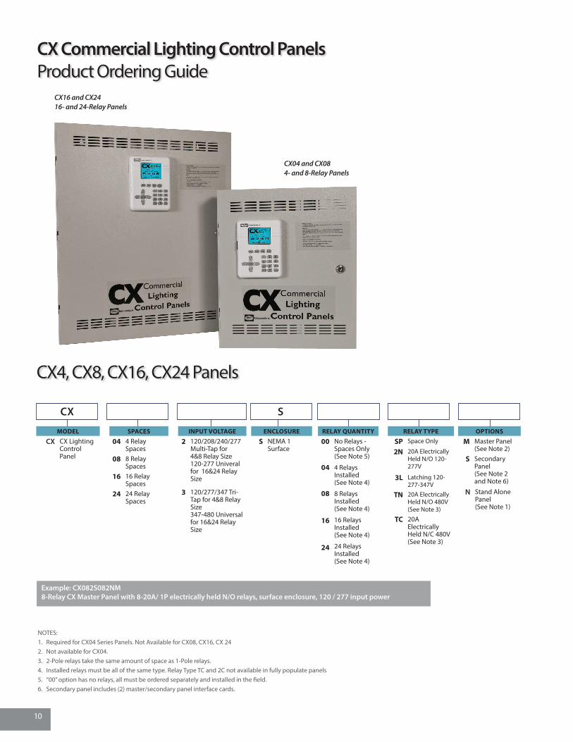
CX16 and CX2416- and 24-Relay Panels
MODEL
CX CX Lighting Control Panel
SPACES
04 4 Relay Spaces
08 8 Relay Spaces
16 16 Relay Spaces
24 24 Relay Spaces
INPUT VOLTAGE
2 120/208/240/277 Multi-Tap for4&8 Relay Size120-277 Univeral for 16&24 Relay Size
3 120/277/347 Tri-Tap for 4&8 Relay Size347-480 Universal for 16&24 Relay Size
ENCLOSURE
S NEMA 1 Surface
RELAY QUANTITY
00
04
08
16
24
No Relays - Spaces Only (See Note 5)
4 Relays Installed (See Note 4)
8 Relays Installed (See Note 4)
16 Relays Installed (See Note 4)
24 Relays Installed (See Note 4)
RELAY TYPE
SP Space Only
2N 20A Electrically Held N/O 120-277V
3L Latching 120-277-347V
TN 20A Electrically Held N/O 480V(See Note 3)
TC 20A Electrically Held N/C 480V(See Note 3)
CX S
NOTES:1. Required for CX04 Series Panels. Not Available for CX08, CX16, CX 242. Not available for CX04.3. 2-Pole relays take the same amount of space as 1-Pole relays.4. Installed relays must be all of the same type. Relay Type TC and 2C not available in fully populate panels5. “00” option has no relays, all must be ordered separately and installed in the field.6. Secondary panel includes (2) master/secondary panel interface cards.
Example: CX082S082NM8-Relay CX Master Panel with 8-20A/ 1P electrically held N/O relays, surface enclosure, 120 / 277 input power
N Stand Alone Panel (See Note 1)
CX04 and CX084- and 8-Relay Panels
CX Commercial Lighting Control PanelsProduct Ordering Guide
CX4, CX8, CX16, CX24 Panels
10

DIMENSIONAL INFORMATION Panel and Mounting
PRODUCT SPECIFICATIONS- CX PANEL ACCESSORIESCX4, CX8, CX16, CX24 Panel
Programming and configuration Programmable via user interface mounted on door Fully programmable by users with door closed and locked Stand Alone, Master, or Secondary Panels. One Master and one Secondary may be connected as a system
Physical NEMA 1 surface enclosure Pre-drilled mounting holes for mounting to wall, KOs provided on top and bottom 4/8 relay and 16/24 relay enclosures are provided with a hinged locking door
Electrical Input 120/208/240/277VAC for 4/8 size, 120-277VAC Universal for 16/24 size Standard, 120/277/347 Optional
Operating environment Location: NEMA 1 interior space Operating temperature: 0° to 50°C (32° to 112°F) Relative humidity (non-condensing): 10% to 90%
Certifications Certified to UL 916 and cUL
CX04 and CX08 4- and 8-Relay Panels14.5” W x 17”H x 4” D
CX16 and CX24 16- and 24-Relay Panels20” W x 24”H x 4” D
CX16, X24 Master OR Secondary PanelCX08 Master OR Secondary Panel
Option Card
Location for
Master Interface Card,
Secondary Interface Card
and/or CX Dimming Card
Option Card
Location for
Master Interface Card,
Secondary Interface Card
and/or CX Dimming Card
11

CXDIMCONTRBD
MODELCXDIMCONTRBD CX Panel 8-Channel
Dimming Controller Option Board
Features• Full range dimming with preset dimming levels• Ramp Up, Fade Down, Minimum Dim Level• Max Dim Level (Demand Response System Settings)• Operates with 0-10V dimmable ballasts• Provides manual and automatic control of dimming levels• Upgrade option to existing and new CX Panels• 8 Dimming channels per card• Works with CAT5 Switches
ORDERING INFORMATION
CXRTN, CXRTC20A/2P, N/O and N/C
CXR3L30/1P, Latching
CXR2N,20A/1P, N/O
MODEL
CXR
RELAY TYPE
2N 20A 1-Pole Electrically Held N/O 120-277V 14KSCCR @ 277VAC
3L 30A 1-Pole Latching 120-277-347V 18KSCCR @ 277VAC, 14KSCCR @ 347VAC
TN 20A 2-Pole Electrically Held N/O 480V 14KSCCR @ 480VAC
TC 20A 2-Pole Electrically Held N/C 480V 14KSCCR @ 480VAC
CXR Relays for use with CX Panel
ORDERING INFORMATION
PRODUCT SPECIFICATIONS- CX DIMMING CARDPower requirements Low Voltage via CX Panel Option Port
Output (Low Voltage Sensors) Eight 0-10V Dimming Channels 0-10V Screw terminals. #16 solid or stranded copper wire. 0-10V output 50mA per channel Four RJ45 Connections for discrete RJ45 CAT5 Switches
User Interface LCD Color Display via CX Panel Supports CAT5/RJ45 Switches
PRODUCT SPECIFICATIONS - CXR RELAYPhysical Mounts inside NEMA 1 surface panel enclosure Pre-drilled mounting hole for securing relay cards Individual relay cards – 1P and 2P are equal in size
Operating environment Location: NEMA 1 interior space Operating temperature: 0°to 50° C (32° to 112° F) Relative humidity (non-condensing): 10% to 90%Certifications Certified to UL 916, UL924 and cULRelay Ratings
CXR Relays
CX Dimming Card
Type Poles VAC Tungsten Flour. Ballast * HID Ballast Motor Rating120 15A 16A 20A 1 HP227 NA 16A 20A 3/4 HP120 20A 30A 30A 1 HP277 NA 30A 30A NA347 NA 20A 20A NA 14K Amps
CXRTN - Elect Held, N.O. 2 480 NA 20A 20A 2 HPCXRTC - Elec Held, N.C. 2 480 NA 20A 20A 2HP
14K Amps
18K Amps
14K Amps
CXR3L- Latching 1
* Electronic Flourescent Ballast Rating is 16A
Characteristics Load Ratings SCCR Rating
CXR2N- Elec Held , N.O 1
12

PRODUCT SPECIFICATIONS- CX PANEL ACCESSORIESPHOTOCELL - LUXSTATLS & LUXSTATLSOElectrical Four jumper-selectable foot candle ranges: 0.3–30fc, 3–300fc; 30–3,000fc; 60–6,000fc Low-voltage Class 2 device Protective hard-plastic cover
Dimensions 2” dia., 1.2” height (50.8mm dia., 30.5mm height)
Certifications UL and cUL listed LUSTATLSO - IP 54 rated
LOW VOLTAGE SWITCHES – LVSM & ZONE5 SERIESElectrical Ratings Each switch: 100mA @ 30VDC Max Each pilot LED: 18-30VDC, internal 2.2kohm resistor
Configurations 1 - 4 buttons, with or without pilot LED
Momentary
Operating environment Indoor use only Operating temperature: 32° to 122°F (0° to 50°C) Relative humidity (non-condensing): 10% to 90%
Dimensions 4.87” dia., 2.44” deep (123.7 mm dia., 62mm deep)
Mounting Single-gang NEMA-style switch box (average switch box) Decorator-style wall plate not included
Low Voltage Switches
Motion SensorsThe CX Panels support direct connection to HCS OMNI Series Stand Alone Motion Sensors featuring IntelliDAPT® technology.
The ceiling mount OMNI series and wall mount LightOWL series sensors can be used with the CX Panel inputs without the use of power packs.
Low Voltage SwitchesThe CX Panels support direct connection to HCS LVS Series Low Voltage momentary contact switches. These switches are available with or without LED indication. Add WH for White or IV for Ivory finish at the end of the part number.
CAT5 Low Voltage Switches for DimmingFor use with the CX Dimming Card, these switched are available in Raise-Lower and Master On/Off configurations.
PhotocellsThe CX Panels support direct connection to HCS Low Voltage Photocells.
Features • Open Loop photosensor • Foot-candle range: 0.3–6,000 fc • Indoor and outdoor versions • Mounts vertically and horizontally • Architecturally attractive design • UL and cUL listed
LightOWL®OMNI®
SWITCHESLVSM1NP Momentary, 1 Button, No PilotLVSM1PL Momentary, 1 Button, w/Pilot LEDLVSM2NP Momentary, 2 Buttons, No PilotLVSM2PL Momentary, 2 Button, w/Pilot LEDsLVSM3NP Momentary, 3 Buttons, No Pilot LVSM3PL Momentary, 3 Buttons, w/Pilot LEDsLVSM4NP Momentary, 4 Buttons, No Pilot
LVSM4PL Momentary, 4 Buttons, w/Pilot LEDs
Z5-SW-MC CAT5 Master On/Off, White
Z5-SW-AVD CAT5 AVD Dimming Switch, White
PHOTOCELL TYPE
LUXSTATLS IndoorLUXSTATLSO Outdoor
Photocells Motion Sensors
ORDERING INFORMATION ORDERING INFORMATIONORDERING INFORMATION
Consult hubbell-automation.com for detailed catalog numbers, specifications and application guidelines.
CX Panel Accessories
13

701 Millennium Blvd.Greenville, SC 29607hubbelllighting.com
Hubbell Lighting Brands:
Alera Lighting
Architectural Area Lighting
Beacon Products
Columbia Lighting
Compass Life Safety
Devine Lighting
Dual-Lite
Hubbell Control Solutions
Hubbell Industrial
Hubbell Outdoor
Kim Lighting
Kurt Versen
Litecontrol
Precision-Paragon [P2]
Prescolite
Progress Lighting
Security Lighting Systems
Spaulding Lighting
Sportsliter Solutions
Sterner
Thomas Research Products
Whiteway
Hubbell Control SolutionsLighting Control Product Lines:
Networked Lighting Controls NX™ Distributed Intelligence controls
Wireless Lighting Controls wiHUBB® Distributed lighting controls wiSCAPE™ Outdoor lighting controls wiSTAR™ Self-powered lighting controls
Daylight Harvesting Controls Zone 5™ Daylighting controls LuxStat Simple daylighting control
Lighting Control Panels CX Commercial Lighting Controls LX Networked Lighting Controls
Occupancy/Vacancy Sensors LightHAWK®2 Wall switch sensor LightOWL® Wall-mount occupancy sensor OMNI® Ceiling-mount occupancy sensor WASP™2 High-mount occupancy sensor Dimming WASP™ Indoor/outdoor sensor
Hubbell, A Name You Can Trust
Hubbell Control Solutions is a strong proponent of innovative, integrated energy-saving lighting controls. From introducing the industry’s first self-adaptive occupancy sensor to today’s advanced wired and wireless distributed intelligence lighting controls, the company continues to offer the most comprehensive line of occupancy sensors on the market. Other products include daylight harvesting and high bay controls.
The brand is part of Hubbell Lighting, one of the largest lighting manufacturers in North America. Hubbell Lighting brands offer products for commercial, industrial and residential markets. The company’s history of innovation extends back to 1886 and Harvey Hubbell’s invention of the very first lighting control device—the pull chain switch.
9601 Dessau Rd., Building One | Austin, Texas 78754T 512-450-1100 | F 512-450-1215www. hubbell-controls.com
Doc # 3225 3-22-2016© 2016 Hubbell Control Solutions. All rights reserved. Subject to change without notice. Trademarks are property of their respective owners.


![AC CIRCUIT BREAKER PANELS [WITHOUT METERS] … · 2015. 2. 3. · 4 BACK LIGHTING All BEP AC and DC panels come with 12 volt DC back lighting. On 24-volt systems, a dropping resistor](https://img.dokumen.tips/doc/110x75/60fae3d357ef1f0904037ed6/ac-circuit-breaker-panels-without-meters-2015-2-3-4-back-lighting-all-bep.jpg)