Embed Size (px)
Citation preview

Hubbell Building Automation CX Commercial Lighting Control Panels
Save Energy, Reduce Project Costs and Increase Control.
CX Commercial Lighting Control Panels
Save Energy, Reduce Project Costs and Increase Control
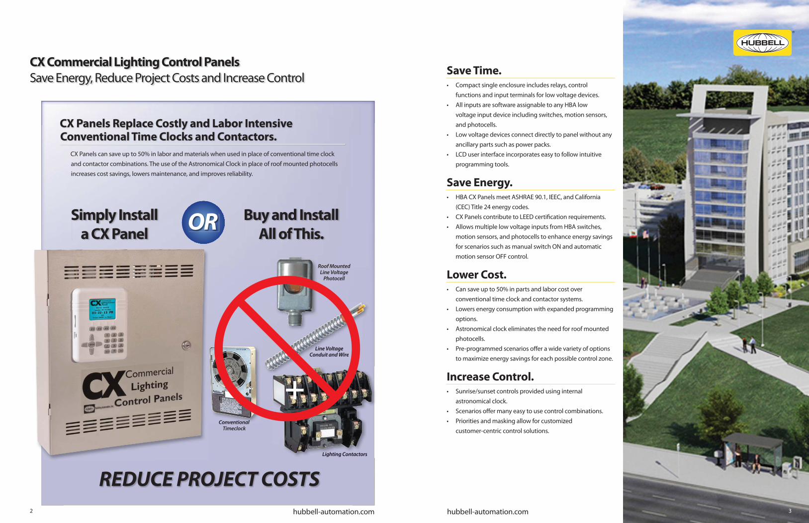
CX Panels can save up to 50% in labor and materials when used in place of conventional time clock and contactor combinations. The use of the Astronomical Clock in place of roof mounted photocells increases cost savings, lowers maintenance, and improves reliability.
Save Time.• Compact single enclosure includes relays, control functions and input terminals for low voltage devices.• All inputs are software assignable to any HBA low voltage input device including switches, motion sensors, and photocells.• Low voltage devices connect directly to panel without any ancillary parts such as power packs. • LCD user interface incorporates easy to follow intuitive programming tools.
Save Energy.• HBA CX Panels meet ASHRAE 90.1, IEEC, and California (CEC) Title 24 energy codes.• CX Panels contribute to LEED certifi cation requirements.• Allows multiple low voltage inputs from HBA switches, motion sensors, and photocells to enhance energy savings for scenarios such as manual switch ON and automatic motion sensor OFF control.
Lower Cost.• Can save up to 50% in parts and labor cost over conventional time clock and contactor systems.• Lowers energy consumption with expanded programming options.• Astronomical clock eliminates the need for roof mounted photocells.• Pre-programmed scenarios off er a wide variety of options to maximize energy savings for each possible control zone.
Increase Control.• Sunrise/sunset controls provided using internal astronomical clock.• Scenarios off er many easy to use control combinations.• Priorities and masking allow for customized customer-centric control solutions.
Roof MountedLine Voltage
Photocell
Line Voltage Conduit and Wire
Lighting Contactors
Conventional Timeclock
Simply Install
a CX Panel
Buy and Install
All of This.OR
REDUCE PROJECT COSTS
Line Voltage Conduit and Wire
Lighting Contactors
Conventional
CX Panels Replace Costly and Labor Intensive Conventional Time Clocks and Contactors.
+
hubbell-automation.com 3hubbell-automation.com2

CX Panels Product Installation Features
Auxiliary Inputs
Individual Mounted Relay Card
Dry Contact Outputs
CX 8-Relay Panel Interior
The CX Series panels are self-contained lighting control systems. All inputs are low voltage and hard-wired to terminal blocks in the panel. Input power supply is multi-tapped or universal for typical service voltages. Line voltage terminals are located with generous space for easy connection.
Easy To Install
Auxiliary Input Features
• Provisions for multiple device control of a single relay or group.
• Scenarios program allows for easy mapping of auxiliary outputs.
Dry Contact Output Features
• Normally open or normally closed output.• Momentary or maintained.• Allows for interconnection to other
building functions such as security, fi re alarm, or building management system.
Relay Card Features• 1-pole and 2-pole relays fi t in the same sized space.• Relay self-identifi es once installed.• Available 20A/1P N/O, or N/C, 20A/2P N/O, or N/C and 30A/1P latching.• 14K SCCR for 20A/1P N/O or N/C, 20A/2P N/O or N/C.• 18K SCCR for 30A/1P latching.
Product Features
1) CX Panel User Interface – The easy to use and understand color LCD Display with keypad has been designed based on input styles of commonly used devices such as cell phones.
2) Panel Door Lock – The CX Panel is designed to be locked once the qualifi ed electrician has completed all connections. All programming, system status, and manual controls are available via the User Interface once the door is secured.
3) Panel Schedule – A panel relay schedule card is included in a protective plastic sleeve to allow for all relay circuits, inputs and outputs to be documented by the installing electrician.
4) Low Voltage Input Device Wiring Diagrams– Indicates point-to-point connection requirements for each type of device.
5) Interconnect Cable to User Interface – This cable may be disconnected to allow for the removal of the door during the panel wiring process. The panel can be powered up and relays manually controlled without the door connected for the electrician to verify circuit connections.
6) Line Voltage Input Leads – These leads are marked for various input supply voltages.
7) Control Power Transformer – This transformer has multi-tap leads to be connected to common input line voltage supply.
8 Control Power Disconnect – A disconnect plug is provided for low voltage input control power to allow for safe removal and replacement of relay cards.
9 Keyhole Mounting – No disassembly of internal components is required to mount CX Panels.
10 Individual Relay Card – Relays are individually mounted for easy replacement, improved reliability and to allow for panels to include any mix of relay types.
11 Relay Card Connector – This connector fi ts into the socket on the panel motherboard to allow for control of relays by the panel.
12 Relay Manual Override Button – Allows for relays to be manually operated. Manual control of relays is also available through the User Interface.
13 Relay Status Light – Indicates relay operation status.
14 Relay Board Input Terminal Block – Any type of low voltage input including Switches, Motion Sensors or Photocells may be connected to any relay input terminal block. These inputs are software assignable as to type and control. Any input can control any relay or group.
15 Line Voltage Control Circuit Terminals – Lighting circuits are connected to these heavy duty screw terminals. Each terminal will accommodate two #14 - #10 stranded or solid copper wire of the same type and size.
16 Auxiliary Inputs – The CX Panel is supplied with additional low voltage inputs to accommodate a wide variety of control scenarios that require more than one input for a relay or group. Any type of low voltage input including Switches, Motion Sensors or Photocells may be connected to any input terminal block. These inputs are software assignable as to type and control. Any input can control any relay or group.
17 Dry Contact Output Terminals – Each Output Terminal allows for the CX Panel to signal other systems with N.O./N.C. momentary or maintained contacts.
18 Master/Secondary Panel Interface Card Connector – Cards provided with the secondary panel provide easy connection with CAT5 or CAT5e cable.
19 Door Hinge – The CX Panel door hinge is designed to allow removal of the door during the installation of line and low voltage wiring for easier access and protection of the user interface. Relay manual override button will operate relays with User Interface cable disconnected from the motherboard.
Wireway Divider - Seperates Line and Low Voltage wiring.
2
2
3
4
5
6
7
89
10
1819
16
9
CX 16/24-Relay Panel
Product Features
1
20
17
11 12 15
14
13
1
2
3
4
5
6
7
8
9
10
11
12
1314
15
16
17
18
19
20
hubbell-automation.com hubbell-automation.com4 5

Easy To ProgramCX Panels Programming Capabilities
The easy to use and understand color LCD Display has been designed based on input styles of commonly used devices such as cell phones.
CX Main Menu.
The CX Panel Main Menu presents easy to understand programming and system status choices. Press ENTER to begin programming from system home screen. Simply scroll up/down and then press ENTER to navigate to menu choices.
It’s so EASY and INTUITIVE that a contractor can complete programming in less than 30 minutes for most projects.
• Simple Arrow navigation and Enter buttons make selections easy.
• Color LCD screen allows for settings to be made in a single screen.
• All Low Voltage Inputs are assignable to any type of control device.
• Help screens are available throughout the program by touching the HELP key when the symbol appears.
• Naming is made easy through selectable name input.• Choose City and State from a large list of
pre-confi gured longitude and latitude values.
Color LCD Display – Allows for most programming to be completed in a single screen. Right side scroll bars appear when more choices are available than are currently visible.
Function Keys – These keys provide programming choices in various screens. Key labels appear on-screen when keys are available.
Alpha-Numeric Keypad – This keypad is used to populate names and numeric values while programming. Tap/Scroll operation is similar to that used for cell phones.
Escape Key – This key takes the user to the previous screen. Warning prompts when changes have been made but not saved.
Help Key – This key will bring up help screens in specifi c locations driven by the fi eld that is highlighted.
Navigation Keys – Allows user to navigate Up/Down/Right/Left/Toggle through editable fi elds to select program choices.
Enter Key – Use this key to make selections.
CX Scenarios Programming
The Scenarios programming feature allows the user to select from a group of pre-programmed control schemes to more easily assign relays and inputs for the desired actions. The use of Scenarios will shorten programming time by only requiring unique input, automatically assigning characteristics, masking and priorities specifi cally associated with the selected behavior.
Outdoor Scenarios:
• Photocell ON/Photocell OFF• Photocell ON/Schedule OFF• Photocell ON/Schedule OFF/Override Switch• Astro-Clock ON/Astro-Clock OFF• Astro-Clock ON/Schedule OFF• Astro ON/Schedule OFF/Override Switch
Indoor Scenarios:
• Switch(s) ON/OFF• Motion Sensor ON/OFF• Manual Switch ON/Auto
Motion Sensor OFF• Photocell ON/OFF• Photocell ON/OFF/
Override Switch• Motion ON/OFF/
Photocell OFF• Switch-Motion ON/OFF/
Photocell OFF• Manual Switch ON/
Motion-Photocell OFF• Schedule ON/Schedule OFF• Schedule ON/Schedule OFF/Override Switch• Schedule ON/Schedule OFF/Blink Override Switch• Schedule OFF/Blink Override Switch• Schedule ON/Schedule OFF/Blink Sweep Switch• Schedule OFF/Blink Sweep Switch• Schedule ON/Schedule OFF/Switch ON-OFF After Hours• Schedule ON/Schedule OFF/Sensor ON-OFF After Hours• Master Override All Programming Switch• Master Override All Programming Exterior Input
Indoor Scenarios
CX Programming Specifi cations
The CX Panel has a diverse set or programming capabilities designed to meet or exceed Energy Code requirements and give maximum fl exibility to building users. The User Interface Main Menu is the gateway to easy input and development of system programming for the project. The system provides the following programming capabilities:
• System Settings for Time and Date, Astronomical Clock and System Global Settings– Astronomical Clock Select from Major U.S. Cities List– Relay Function, Blink Alert, and After Hours Sweep– 4 Open/Close Time Schedules– Panel Names, Power ON Settings, and Display Settings
• Scenarios Menu allows for the application of pre-programmed Indoor and Outdoor templates– User only needs to input unique information related to the
selected Scenario– Scenario auto-populates data related to specifi c chosen
behavior
• 32 Groups are available that can include any or all relays
• 64 Schedules are available that can be ON only, OFF only or with both ON and OFF events– Schedules may be selected as M-F, M-F + Saturday, or All Days
customizable per day– All schedules may include Holidays– Date ranges may be set for any Schedule– 4 levels of Priority can be applied to ON and OFF events
independently
• Holidays may be “Block Schedule” dates or may have Holiday Schedules applied – A master list of standard holidays may be chosen as recurring
year-after-year dates– 99 custom Month-Day-Years dates may be programmed– 4 Holiday schedules can be created and applied to any of the
99 dates
• Inputs are program assignable to any type of device– Switches, Motion Sensors, or Photocells can be connected to
any input– Inputs may be jumpered and mapped to additional relays or
groups– 4 levels of Priority can be applied to ON and OFF events
independently – Masking can be applied to ON and OFF events independently– Panel provides enough device power for one input device per
relay
• Outputs are programmable to activate by any schedule or input – Maintained or Momentary, Normally Open or Normally Closed
contact form selection
• System Tools include Access Control, Manual Control, Diagnostics and System Information– Program Save/Back-up/Restore– Upload/Save Program and Logging with SD Card or PC
hubbell-automation.com hubbell-automation.com6 7

CX Panel Typical Input Connections
CX Commercial Lighting Control Panels
CX Master and Stand Alone, and Secondary Panels
CX Master and Secondary Panel Connections
CX Panels Overview.
The Hubbell Building Automation CX Commercial Lighting Control Panels provide feature-rich and cost eff ective lighting control for maximum energy savings. The LCD User interface is located in the door and utilizes simple and intuitive scrolling menus to program, check status or update the panel. The easy to use Pre-Programmed Scenarios Menu makes project com-missioning simple and fast.
CX Relays Overview.
The CX Panels have 5 types of available CXR relays. Each relay is individually board mounted and can be installed in any combination in the panel. Types include electrically held normally open (N.O.), electrically held normally closed (N.C.),
and latching. Ratings are 20A/1P 20A/2P, and 30A/1P. Pre-Confi gured Panels are available with relays of the same type. Combinations of any relay type must be ordered separately and fi eld installed into Space Only standard panels.
4-Relay Stand Alone1 (4-Relay Panel is not available as a master or secondary panel.)
8-Relay Master
CX04 / CX08 Confi gurations
CX16 / CX24 Confi gurations
8-Relay Secondary
Note:1. 4-relay panels are not available as Master or Secondary.
8-Relay Master16-Relay Master24-Relay Master
CX Panel (Any size or type)
8-Relay Secondary16-Relay Secondary24-Relay Secondary
16-Relay Secondary
16-Relay Master 24-Relay Master
24-Relay Secondary
CXR Relays
Panel Mounted or Individual
CAT 5 or CAT5e Cable
750’ Maximum
Low Voltage Momentary Switch
Low Voltage Momentary Switch
Photocell
Motion Sensors
InterfaceMaster/Secondary
CardMaster/Secondary Interface Card(Interface cards aresupplied with RJ-45 jack and bussed terminal block)
Low Voltage devices that control the same zone may
be parallel wired.
Master PanelIncludes User Interface
Secondary PanelIncludes 2 each - Master/SecondaryInterface Cards
Panel supports one device per relay.CXRTN, CXRTC14K SCCR
CXR3L18K SCCR
CXR2N, CXR2C14K SCCR
Pictured above—left to right, CXR2N & CXR2C 20A/1P Relays; CXR3L 30A/1P Relay; CXRTN & CXRTC 20A/2P Relays.
CX Master / Secondary Panels are easily applicable to a wide range of small to medium commercial projects.
Flexible Design Application
hubbell-automation.com 98
CABLES 1 3 #18 insulated class 2 copper wire. 2 #18 insulated class 2 copper wire. Number of wires varies based on number of buttons and LED indication.
1
1 1
1
2
2 2

CXR Relays
CX Panel Accessories
CX Commercial Lighting Control Panels
Product Ordering Guide
CX4, CX8, CX16, CX24 Panels
Photocells Low VoltageSwitches
CX04 and CX084- and 8-Relay Panels14.5” wide x 20” highx 4” deep
CX16 and CX2416- and 24-Relay Panels20” wide x 24” high x 4” deep
MODEL
CXR
RELAY TYPE
2N 20A 1-Pole Electrically Held N/O 120-277V 14KSCCR @ 277VAC
2C 20A 1-Pole Electrically Held N/C 120-277V 14KSCCR @ 277VAC
3L 30A 1-Pole Latching 120-277-347V 18KSCCR @ 277VAC, 14KSCCR @ 347VAC
TN 20A 2-Pole Electrically Held N/O 480V 14KSCCR @ 480VAC
TC 20A 2-Pole Electrically Held N/C 480V 14KSCCR @ 480VAC
RELAY TYPE
LVSM1NP Momentary, 1 Button, No Pilot
LVSM1PL Momentary, 1 Button, w/Pilot LED
LVSM2NP Momentary, 2 Buttons, No Pilot
LVSM2PL Momentary, 2 Button, w/Pilot LEDs
LVSM3NP Momentary, 3 Buttons, No Pilot
LVSM3PL Momentary, 3 Buttons, w/Pilot LEDs
LVSM4NP Momentary, 4 Buttons, No Pilot
LVSM4PL Momentary , 4 Buttons, w/Pilot LEDs
PHOTOCELL TYPE
LUXSTATLS Indoor
LUXSTATLSO Outdoor
DIMENSIONAL INFORMATION
Panel and Mounting
CX04 and CX08 CX16 and CX24
MODEL
CX CX Lighting Control Panel
SPACES
04 4 Relay Spaces
08 8 Relay Spaces
16 16 Relay Spaces
24 24 Relay Spaces
INPUT VOLTAGE
2 120/208/240/277 Dual Tap for4&8 Relay Size120-277 Univeral for 16&24 Relay Size
3 120/277/347 Tri-Tap for 4&8 Relay Size347-480 Universal for 16&24 Relay Size
ENCLOSURE
S NEMA 1 Surface
RELAY QUANTITY
00
04
08
16
24
No Relays - Spaces Only (See Note 5)
4 Relays Installed (See Note 4)
8 Relays Installed (See Note 4)
16 Relays Installed (See Note 4)
24 Relays Installed (See Note 4)
RELAY TYPE
SP Space Only
2N 20A Electrically Held N/O 120-277V
2C 20A Electrically Held N/C (120-277V)
3L Latching 120-277-347V
TN 20A Electrically Held N/O 480V(See Note 3)
TC 20A Electrically Held N/C 480V(See Note 3)
OPTIONS
N Stand Alone Panel (See Note 1)
M Master Panel (See Note 2)
S Secondary Panel (See Note 2 and Note 6)
CX
NOTES:
1. Required for CX04 Series Panels. Not Available for CX08, CX16, CX 242. Not available for CX04.3. 2-Pole relays take the same amount of space as 1-Pole relays.4. Installed relays must be all of the same type. Relay Type TC and 2C not available in
fully populate panels5. “00” option has no relays, all must be installed in the fi eld.6. Secondary panel includes (2) master/secondary panel interface cards.
Example: CX082S082NM
8-Relay CX Master Panel with 8-20A / IP electrically held N/O relays, surface enclosure, 120 / 277 input power
Motion Sensors
The CX Panels support direct con-nection to HBA Omni™ Series Stand Alone Motion Sensors featuring IntelliDAPT®.
The ceiling mount OMNI™ series and wall mount LightOWL™ series sen-sors can be used with the CX Panel inputs without the use of power packs.
Consult hubbell-automation.com for detailed catalog numbers, specifi ca-tions and application guidelines.
Low Voltage Switches
The CX Panels support direct connection to HBA LVS Series Low Voltage momentary contact switches. These switches are available with or without LED indication. Add WH for White or IV for Ivory fi nish at the end of the part number.
ORDERING INFORMATION
Photocells
The CX Panels support direct connection to HBA Low Voltage Photocells. Features
• Open Loop photosensor • Foot-candle range: 0.3–6,000 fc • Indoor and outdoor versions • Mounts vertically and horizontally • Architecturally attractive design • UL and cUL listed
ORDERING INFORMATION
Panel Dimensions17”H x 14.5”W x 4”D
Panel Dimensions24”H x 20”W x 4”D
CXRTN, CXRTC20A/2P, N/O
and 20A/2P, N/O and N/CCXR3L
30/1P, LatchingCXR2N, CXR2C
20A/1P, N/O and N/C
LightOWL™
Motion Sensors
OMNI™
CXR Relays for use with CX Panel
hubbell-automation.com hubbell-automation.com10 11
Hubbell Building Automation
CX Product Specifi cations
CX4, CX8, CX16, CX24 Panel
Programming and confi guration • Programmable via user interface mounted on door • Fully programmable by users with door closed and locked • Stand Alone, Master, or Secondary Panels. One Master and one Secondary may be connected as a systemPhysical • NEMA 1 surface enclosure • Pre-drilled mounting holes for mounting to wall, KOs provided on top and bottom • 4/8 relay and 16/24 relay enclosures are provided with a hinged locking doorElectrical Input • 120/208/240/277VAC for 4/8 size, 120-277VAC Universal for 16/24 size Standard, 120/277/347 OptionalOperating environment • Location: NEMA 1 interior space • Operating temperature: 0°–50° C (32°–112° F) • Relative humidity (non-condensing): 10%–90%Certifi cations • Certifi ed to UL 916 and cUL
CXR Relay
Physical • Mounts inside NEMA 1 surface panel enclosure • Pre-drilled mounting hole for securing relay cards • Individual relay cards – 1P and 2P are equal in sizeOperating environment • Location: NEMA 1 interior space • Operating temperature: 0°–50° C (32°–112° F) • Relative humidity (non-condensing): 10%–90%Certifi cations • Certifi ed to UL 916, UL924 and cULCXR Relay Ratings
CX PANEL ACCESSORIES
Photocell LUXSTATLS & LUXSTATLSO
Electrical • Four jumper-selectable foot candle ranges: 0.3–30fc, 3–300fc; 30–3,000fc; 60–6,000fc • Low-voltage Class 2 device • Protective hard-plastic coverDimensions • 2” diameter x 1.2” height (50.8 diameter x 30.5mm height)Certifi cations • UL and cUL listed
Low Voltage Switches – LVSM Series
Electrical Ratings • Each switch: 100mA @ 30VDC Max • Each pilot LED: 18-30VDC, internal 2.2kohm resistorConfi gurations • 1 - 4 buttons, with or without pilot LED • MomentaryOperating environment • Indoor use only • Operating temperature: 32° – 122°F (0° - 50°C) • Relative humidity (non-condensing): 10%-90%Dimensions • 4.87” dia., 2.44” deep (123.7 mm dia., 62mm deep)Mounting • Single-gang NEMA-style switch box (average switch box) • Decorator-style wall plate not included
Hubbell Building Automation, Inc.9601 Dessau Road, Building One, Suite 100 | Austin, Texas 78754 USA[512] 450.1100 | [888] 698.3242
ver. 3: 10-2011
*Electronic Fluoresent Ballast Rating is 16A
hubbell-automation.com


![Hubbell Bulletin [EMV] - Gas, Electric, Steam, Indirect ... bulletin [EMV].pdf · Hubbell Model EMV EMERGENCY SAFETY APPLICATIONS TEPID WATER HEATING SYSTEMS Hubbell Electric Heater](https://img.dokumen.tips/doc/110x75/5b9f5ca709d3f2385c8b9e68/hubbell-bulletin-emv-gas-electric-steam-indirect-bulletin-emvpdf.jpg)