Embed Size (px)
Citation preview
Physics Seminar, DESY, January 9th, 2007. Jacek Sekutowicz
1/44
CW and Near-CW Operation of a Superconducting LinacDriving a FEL Facility*
Jacek Sekutowicz
* Work partially supported by EU under contract No. 011935 (EUROFEL)
Physics Seminar, DESY, January 9th, 2007. Jacek Sekutowicz
2/44
Outlook
Motivation
Parameter set for the cw and near-cw operation
Status of the IOT transmitter upgrade
Status of the Nb-Pb gun
Status of the HOM couplers feedthrough and output line
Final Remarks
Physics Seminar, DESY, January 9th, 2007. Jacek Sekutowicz
3/44
Motivation for an increased duty factor
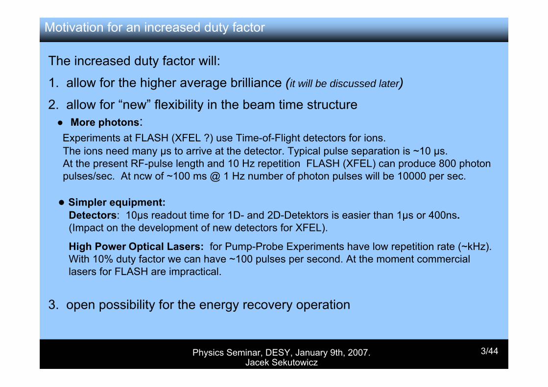
The increased duty factor will:
1. allow for the higher average brilliance (it will be discussed later)
2. allow for “new” flexibility in the beam time structure More photons: Experiments at FLASH (XFEL ?) use Time-of-Flight detectors for ions. The ions need many µs to arrive at the detector. Typical pulse separation is ~10 µs.At the present RF-pulse length and 10 Hz repetition FLASH (XFEL) can produce 800 photon pulses/sec. At ncw of ~100 ms @ 1 Hz number of photon pulses will be 10000 per sec.
Simpler equipment:Detectors: 10µs readout time for 1D- and 2D-Detektors is easier than 1µs or 400ns.(Impact on the development of new detectors for XFEL).
High Power Optical Lasers: for Pump-Probe Experiments have low repetition rate (~kHz). With 10% duty factor we can have ~100 pulses per second. At the moment commercial lasers for FLASH are impractical.
3. open possibility for the energy recovery operation
Physics Seminar, DESY, January 9th, 2007. Jacek Sekutowicz
4/44
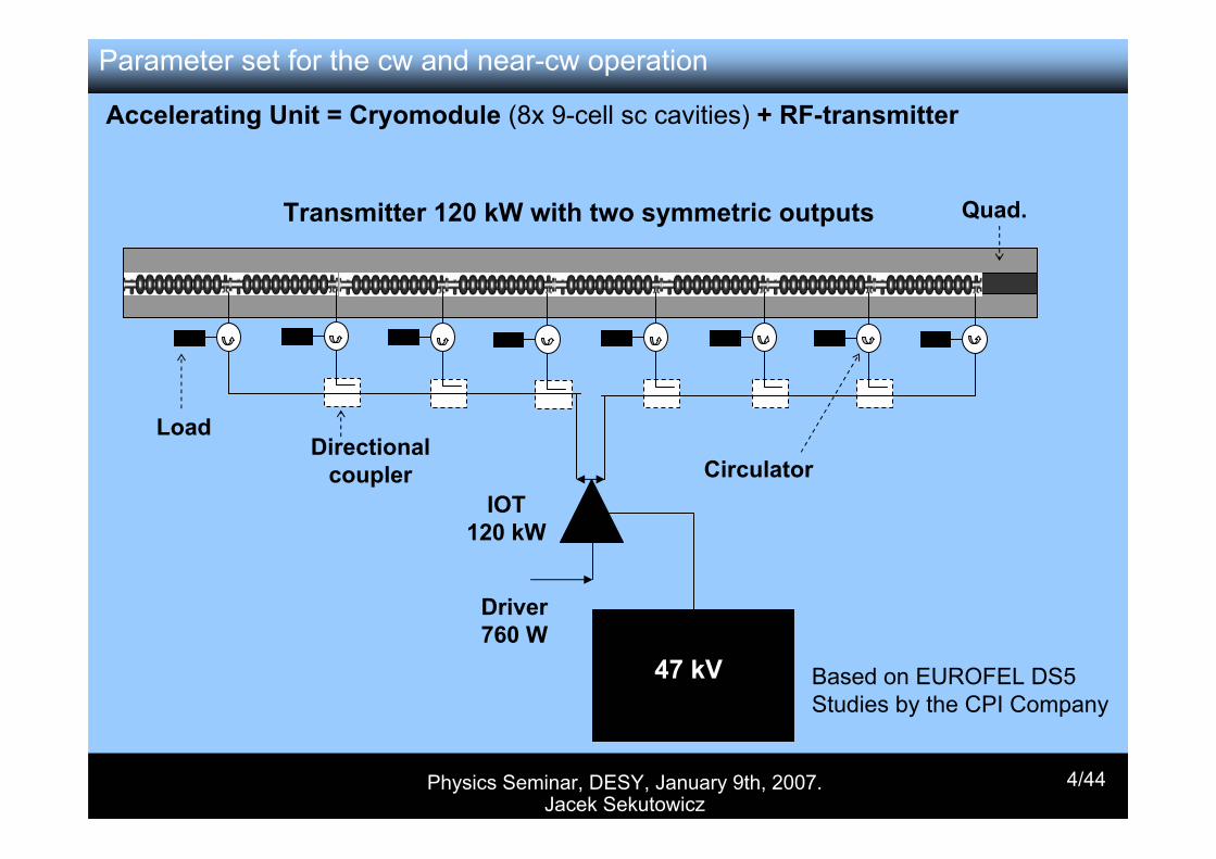
Quad.
IOT120 kW
Driver760 W
Directional coupler
Load
Circulator
47 kV
Transmitter 120 kW with two symmetric outputs
Based on EUROFEL DS5 Studies by the CPI Company
Accelerating Unit = Cryomodule (8x 9-cell sc cavities) + RF-transmitter
Parameter set for the cw and near-cw operation
Physics Seminar, DESY, January 9th, 2007. Jacek Sekutowicz
5/44
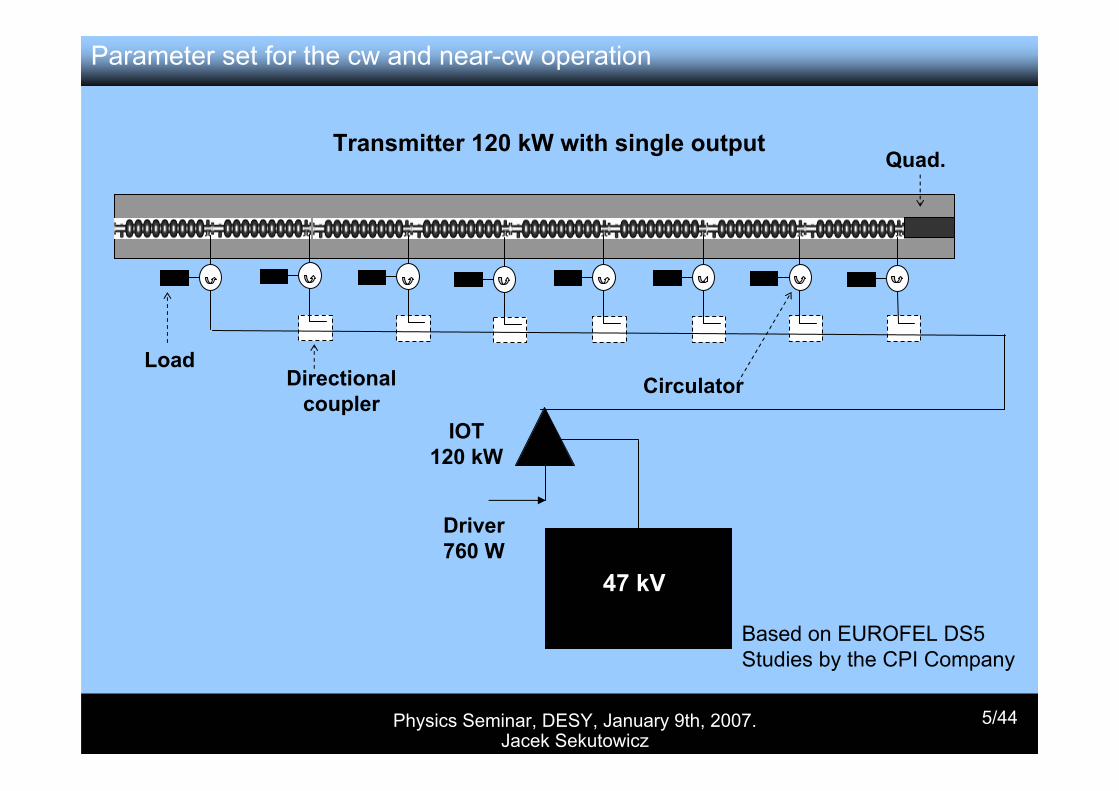
Transmitter 120 kW with single output
Based on EUROFEL DS5 Studies by the CPI Company
Quad.
IOT120 kW
Driver760 W
Directional coupler
LoadCirculator
47 kV
Parameter set for the cw and near-cw operation
Physics Seminar, DESY, January 9th, 2007. Jacek Sekutowicz
6/44
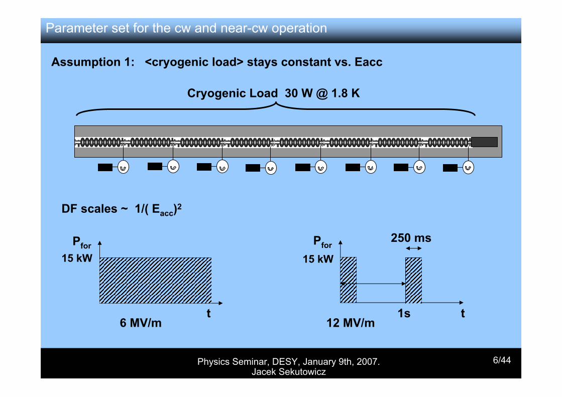
Assumption 1: <cryogenic load> stays constant vs. Eacc
Cryogenic Load 30 W @ 1.8 K
DF scales ~ 1/( Eacc)2
Pfor
t
15 kWPfor
t1s
250 ms15 kW
6 MV/m 12 MV/m
Parameter set for the cw and near-cw operation
Physics Seminar, DESY, January 9th, 2007. Jacek Sekutowicz
7/44
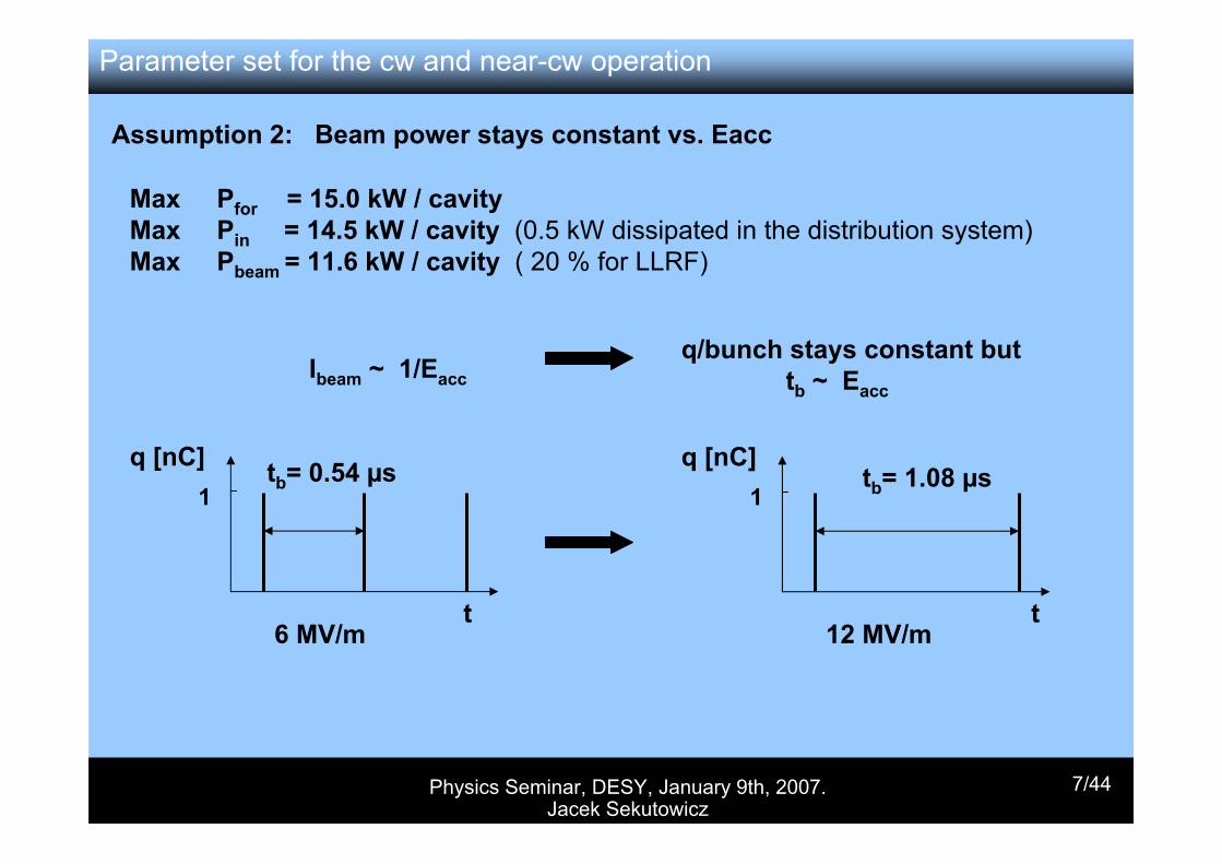
Ibeam ~ 1/Eaccq/bunch stays constant but
tb ~ Eacc
q [nC]
t
1
6 MV/m
tb= 0.54 µs
t12 MV/m
q [nC]1
tb= 1.08 µs
Max Pfor = 15.0 kW / cavityMax Pin = 14.5 kW / cavity (0.5 kW dissipated in the distribution system)Max Pbeam = 11.6 kW / cavity ( 20 % for LLRF)
Assumption 2: Beam power stays constant vs. Eacc
Parameter set for the cw and near-cw operation

Physics Seminar, DESY, January 9th, 2007. Jacek Sekutowicz
8/44
23.220.317.414.511.68.75.8[GeV]XFEL Energy for 116 acc. units
14.514.514.514.513.212.412.1[kW]Total RF-peak power/cavity: beam + microphonics
14182434343434[Hz]Max. allowed microphonics peak-peak
36272014116.73.1[106]Opt. Qext to keep power ≤ 14.5 kW/cavity
0.0530.0810.1290.2200.4120.8571.855[106]Number of 1 nC bunches/s
2.161.891.621.351.080.810.54[µs]Bunch spacing when charge/bunch = 1nC
0.460.530.620.740.931.241.86[mA]Beam current
1211572122994466941000[ms]Pulse length
1141522082974446931000[ms]Beam time
12.115.721.229.944.669.4100[%]Duty Factor
247.7190.7141.4100.267.243.229.6[W]Total Loss at 2K/cryomodule for DF = 100%
2.02.02.02.02.02.02.0[1010]Qo
24.0421.0318.0315.0212.029.016.01[MV/m]Eacc
2001751501251007550[MeV]Energy gain /Accelerating Unit
Operating parameters for the Acc. Unit and for a XFEL-like linac with 116 Units.
Parameter set for the cw and near-cw operation
Physics Seminar, DESY, January 9th, 2007. Jacek Sekutowicz
9/44
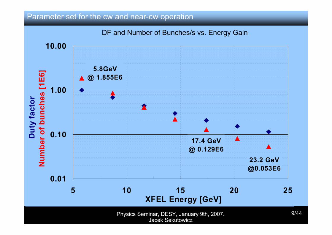
DF and Number of Bunches/s vs. Energy Gain
0.05 GeV @1.855 E6
0.2 GeV @0.053E6
0.01
0.10
1.00
10.00
0.05 0.1 0.15 0.2DE/Unit [GeV]
Dut
y fa
ctor
Num
ber o
f bun
ches
[1E6
]
17.4 GeV @ 0.129E6
5.8GeV @ 1.855E6
23.2 GeV @0.053E6
0.01
0.10
1.00
10.00
5 10 15 20 25XFEL Energy [GeV]
Dut
y fa
ctor
Num
ber o
f bun
ches
[1E6
]
Parameter set for the cw and near-cw operation
Physics Seminar, DESY, January 9th, 2007. Jacek Sekutowicz
10/44
11
12
13
14
15
16
17
18
0 8 16 24 32 δf peak-peak [Hz]
Psource [kW]
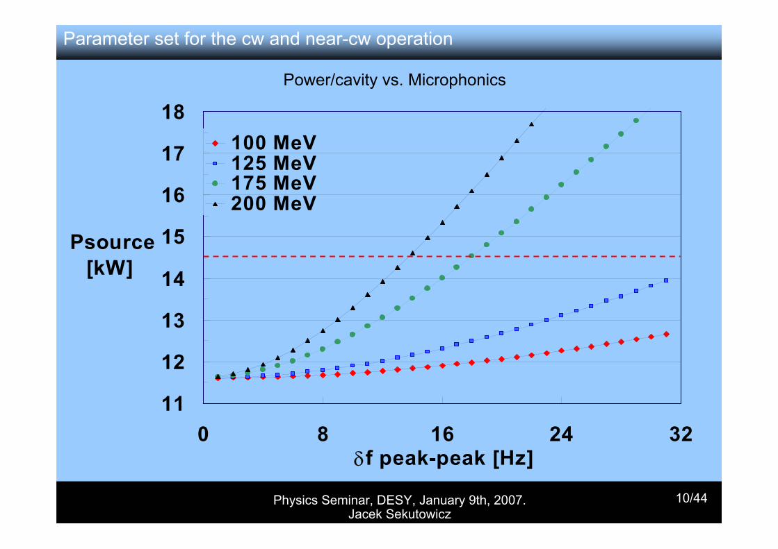
100 MeV125 MeV175 MeV200 MeV
Power/cavity vs. Microphonics
Parameter set for the cw and near-cw operation
Physics Seminar, DESY, January 9th, 2007. Jacek Sekutowicz
11/44
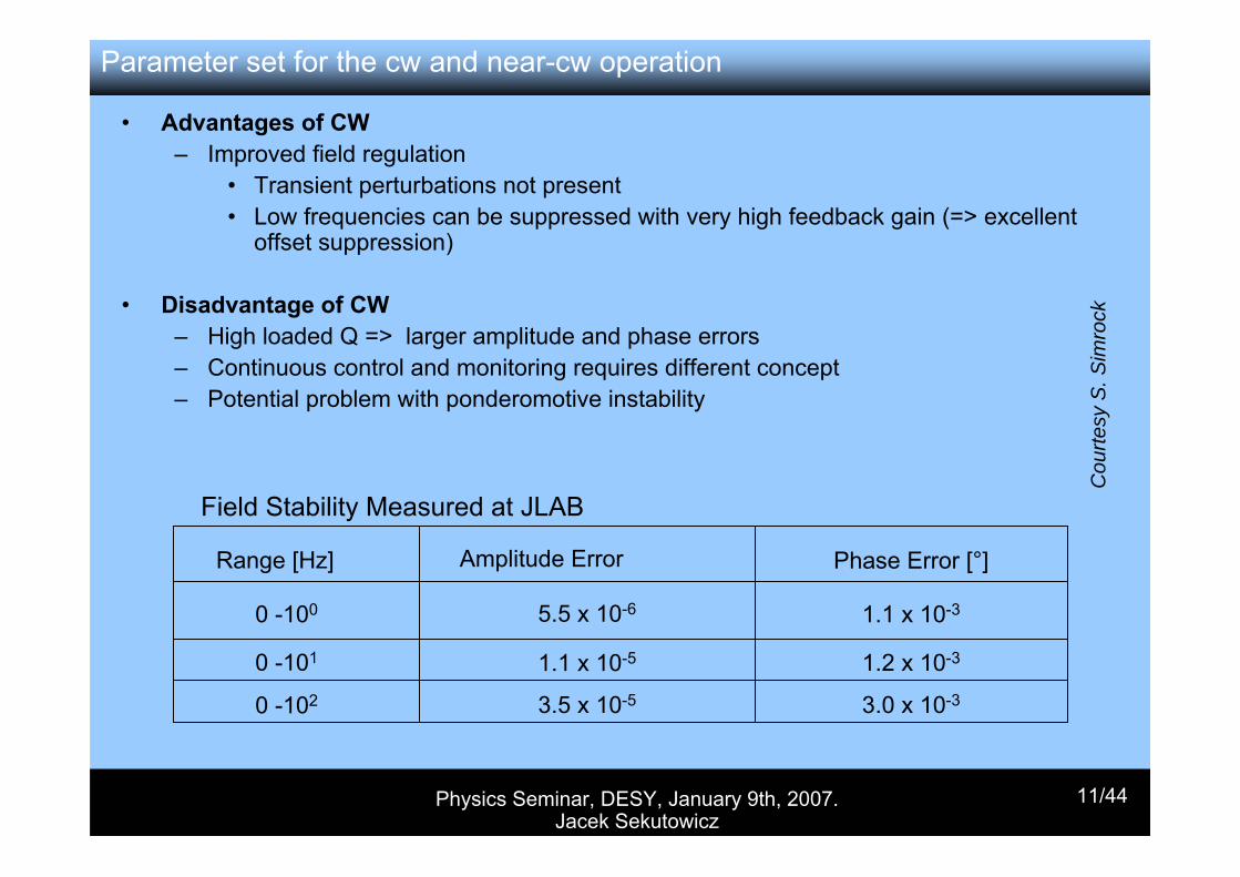
• Advantages of CW– Improved field regulation
• Transient perturbations not present• Low frequencies can be suppressed with very high feedback gain (=> excellent
offset suppression)
• Disadvantage of CW– High loaded Q => larger amplitude and phase errors– Continuous control and monitoring requires different concept– Potential problem with ponderomotive instability
Field Stability Measured at JLAB
Range [Hz] Amplitude Error Phase Error [°]
0 -100 5.5 x 10⁻⁶ 1.1 x 10⁻³
0 -101 1.1 x 10⁻⁵ 1.2 x 10⁻³
0 -102 3.5 x 10⁻⁵ 3.0 x 10⁻³
Parameter set for the cw and near-cw operation
Cou
rtesy
S. S
imro
ck
Physics Seminar, DESY, January 9th, 2007. Jacek Sekutowicz
12/44
Status of the IOT transmitter upgrade
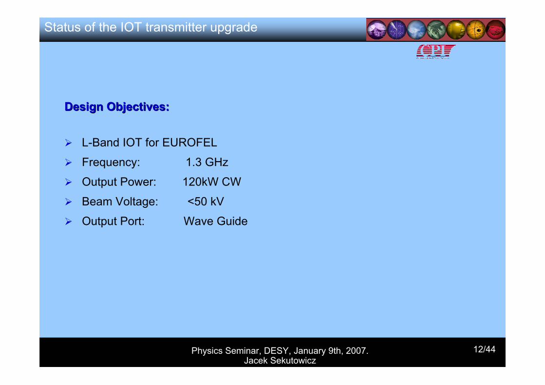
Design Objectives:Design Objectives:
L-Band IOT for EUROFEL
Frequency: 1.3 GHz
Output Power: 120kW CW
Beam Voltage: <50 kV
Output Port: Wave Guide
Physics Seminar, DESY, January 9th, 2007. Jacek Sekutowicz
13/44
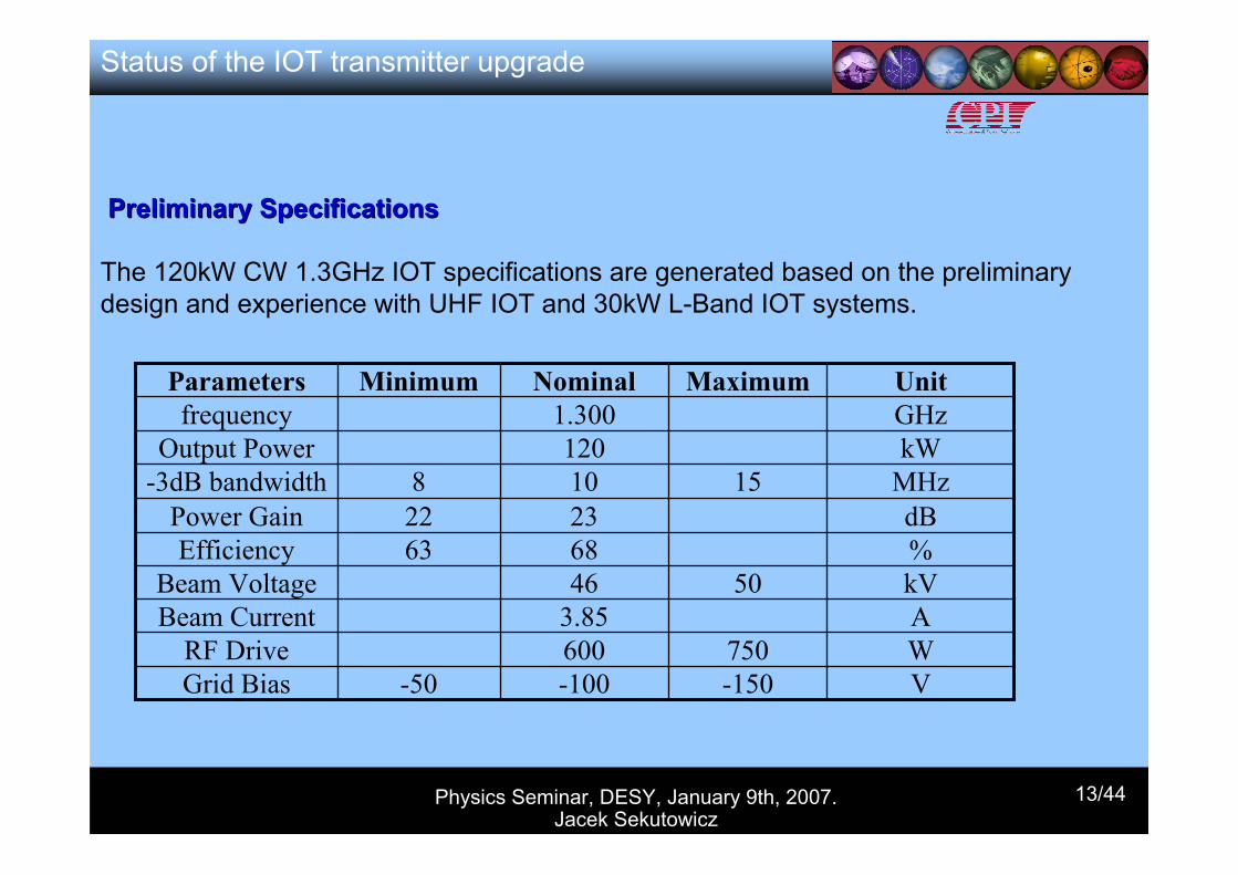
Preliminary SpecificationsPreliminary Specifications
The 120kW CW 1.3GHz IOT specifications are generated based on the preliminary design and experience with UHF IOT and 30kW L-Band IOT systems.
A3.85Beam Current
V-150-100-50Grid Bias
%6863Efficiency
W750600RF Drive
kV5046Beam Voltage
2310120
1.300Nominal
dB22 Power Gain MHz158-3dB bandwidthkWOutput PowerGHzfrequencyUnitMaximumMinimumParameters
Status of the IOT transmitter upgrade
Physics Seminar, DESY, January 9th, 2007. Jacek Sekutowicz
14/44
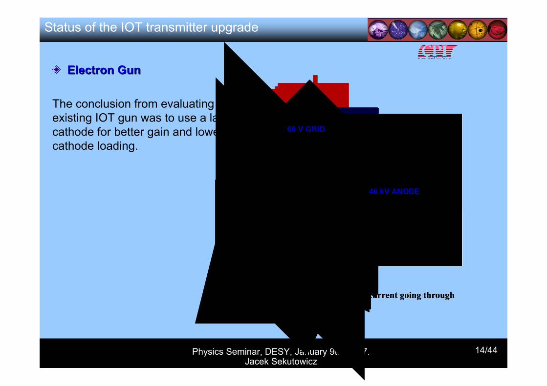
Electron GunElectron Gun
The conclusion from evaluating the existing IOT gun was to use a larger cathode for better gain and lower cathode loading.
Plot of the 17 A beam current going throughthe drift tube
46 kV ANODE
60 V GRID
Plot of the 17 A beam current going throughthe drift tube
46 kV ANODE
60 V GRID
Status of the IOT transmitter upgrade
Physics Seminar, DESY, January 9th, 2007. Jacek Sekutowicz
15/44
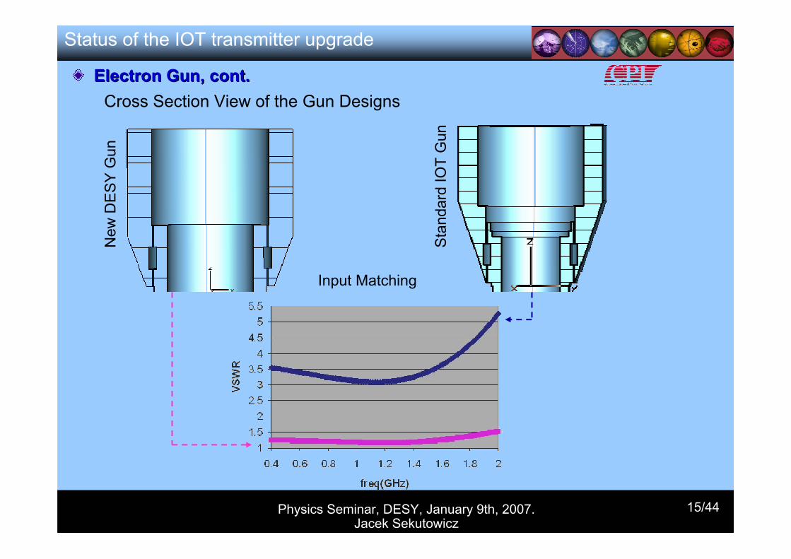
Electron Gun, cont.Electron Gun, cont.
Status of the IOT transmitter upgrade
Cross Section View of the Gun DesignsN
ew D
ES
Y G
un
Sta
ndar
d IO
T G
un
Input Matching
Physics Seminar, DESY, January 9th, 2007. Jacek Sekutowicz
16/44
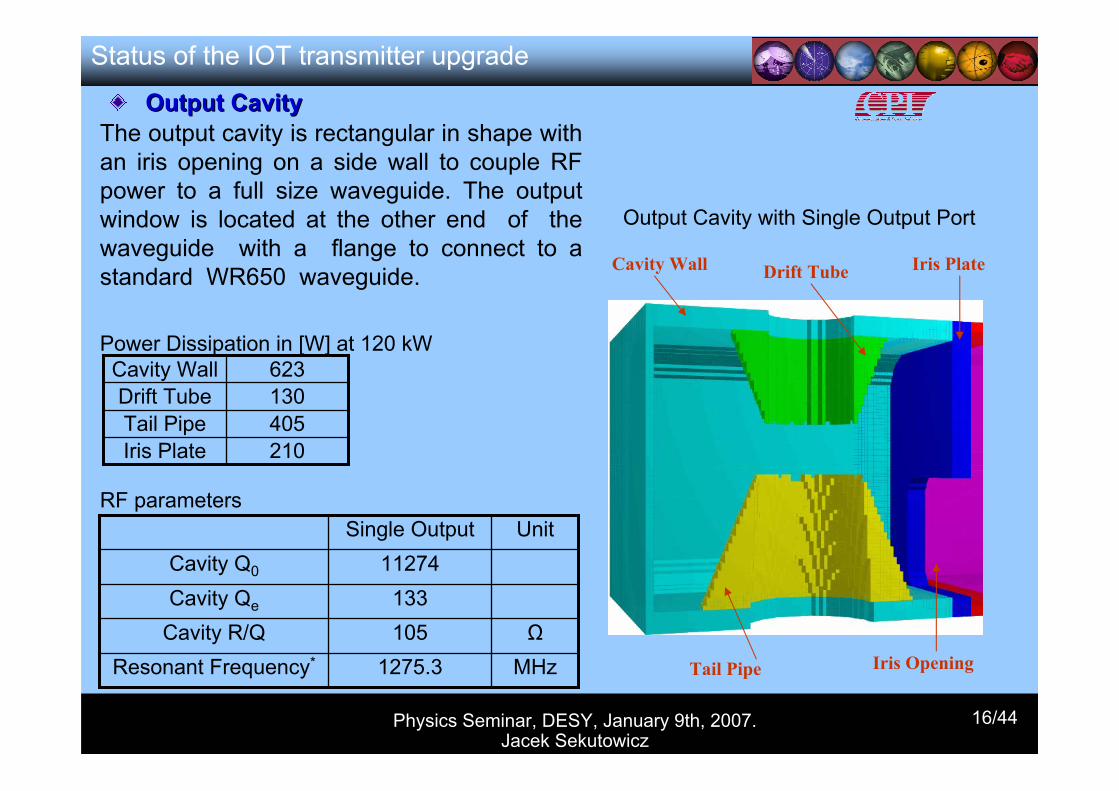
Output CavityOutput CavityThe output cavity is rectangular in shape with an iris opening on a side wall to couple RF power to a full size waveguide. The output window is located at the other end of the waveguide with a flange to connect to a standard WR650 waveguide.
210Iris Plate405Tail Pipe130Drift Tube623Cavity Wall
Power Dissipation in [W] at 120 kW
Cavity Wall Drift Tube Iris Plate
Tail Pipe Iris Opening
Output Cavity with Single Output Port
133Cavity Qe
MHz1275.3Resonant Frequency*
Ω105Cavity R/Q
11274Cavity Q0
Unit Single OutputRF parameters
Status of the IOT transmitter upgrade
Physics Seminar, DESY, January 9th, 2007. Jacek Sekutowicz
17/44
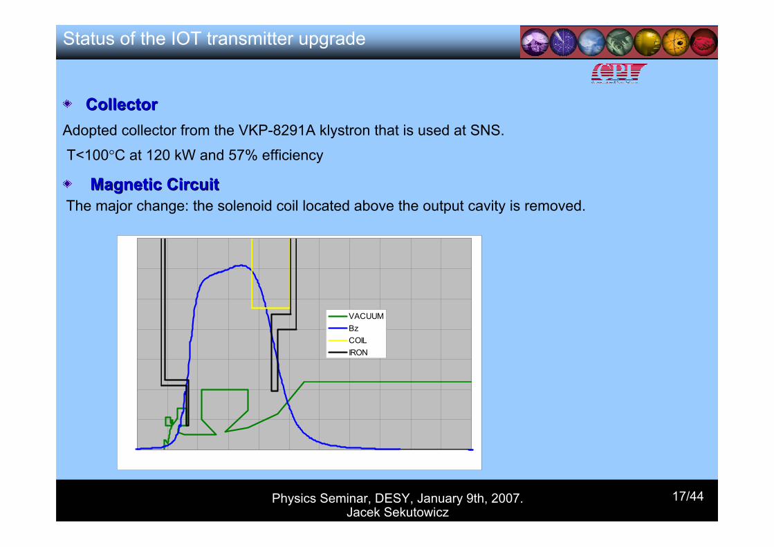
CollectorCollectorAdopted collector from the VKP-8291A klystron that is used at SNS.
T<100°C at 120 kW and 57% efficiency
Magnetic CircuitMagnetic CircuitThe major change: the solenoid coil located above the output cavity is removed.
VACUUMBzCOILIRON
Status of the IOT transmitter upgrade
Physics Seminar, DESY, January 9th, 2007. Jacek Sekutowicz
18/44
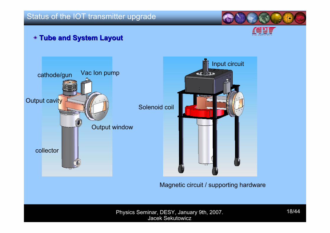
cathode/gun
Output cavity
collector
Vac Ion pump
Output window
Magnetic circuit / supporting hardware
Input circuit
Solenoid coil
Tube and System LayoutTube and System Layout
Status of the IOT transmitter upgrade
Physics Seminar, DESY, January 9th, 2007. Jacek Sekutowicz
19/44
Future Works at CPIFuture Works at CPI
In order to have superb performance, optimization will continue in the following areas,
Cathode and grid performance, cooling and packaging.
Magnetic focusing circuit.
Output cavity: build cold test model to confirm the modeling.
System integration.
Cooling system.
Input circuit modification.
Status of the IOT transmitter upgrade
Physics Seminar, DESY, January 9th, 2007. Jacek Sekutowicz
20/44
Studies on the technical feasibility of the 120 kW transmitter were proposed in 2005 in the frame of the EUROFEL project.
The design can be ready in March 2007 (seven month before the schedule)
It seems possible to build the first single output prototype (CPI revised quotation is ready) but we do not have funding (yet ?)
The first test can be carried out at CPI in 2007/2008
Status of the IOT transmitter upgrade
?then we could install this tube at CMTB at DESY to learn more about:
stability of the cryogenic system at the cw and ncw operation
thermal capability of components at higher duty factor (input and HOM couplers, RF-distribution system….)
optimization of LLRF for the cw operation and the stability of amplitude and phase
……
all this will be very beneficial for the XFEL upgrade and for other FELs (FLASH ?)
Physics Seminar, DESY, January 9th, 2007. Jacek Sekutowicz
21/44
Status of the Nb-Pb gun
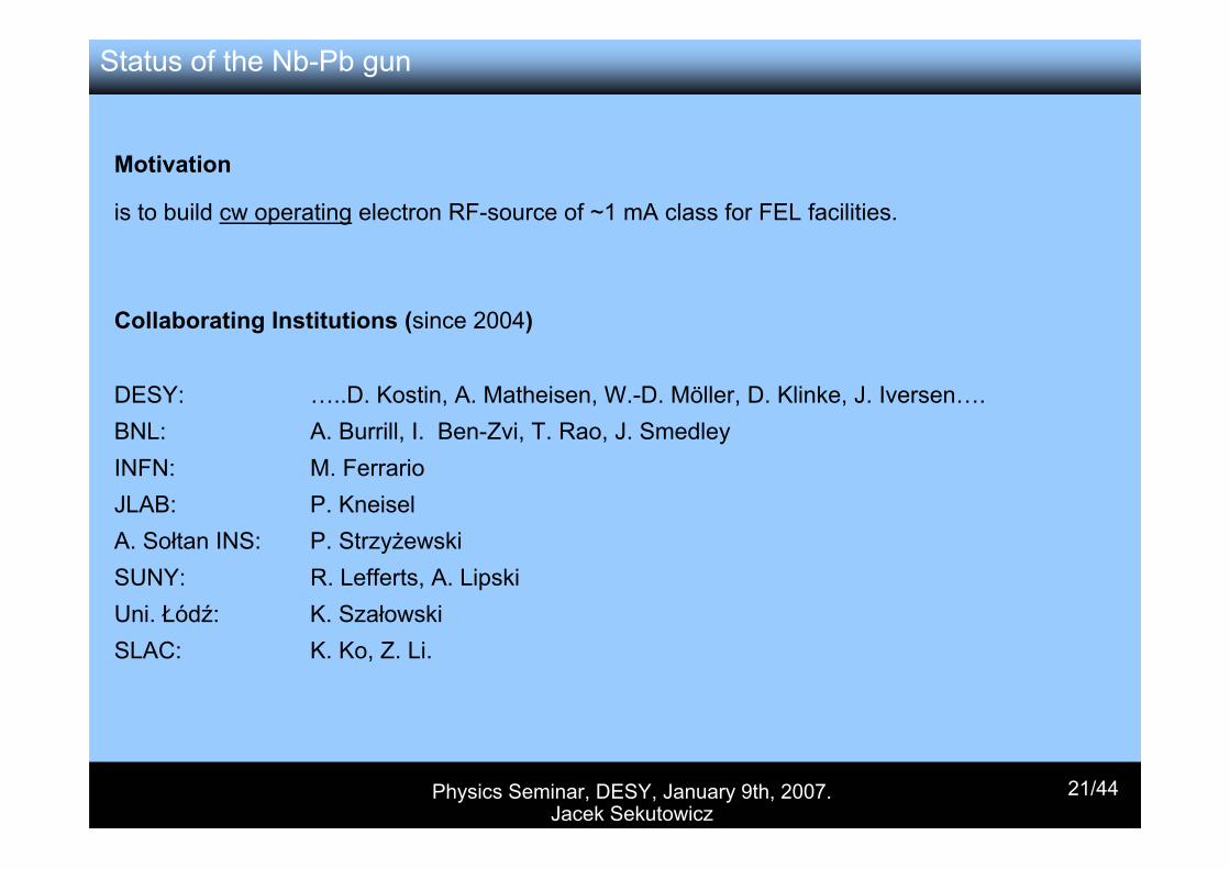
Motivation
is to build cw operating electron RF-source of ~1 mA class for FEL facilities.
DESY: …..D. Kostin, A. Matheisen, W.-D. Möller, D. Klinke, J. Iversen….BNL: A. Burrill, I. Ben-Zvi, T. Rao, J. SmedleyINFN: M. FerrarioJLAB: P. KneiselA. Sołtan INS: P. StrzyżewskiSUNY: R. Lefferts, A. LipskiUni. Łódź: K. SzałowskiSLAC: K. Ko, Z. Li.
Collaborating Institutions (since 2004)
Physics Seminar, DESY, January 9th, 2007. Jacek Sekutowicz
22/44
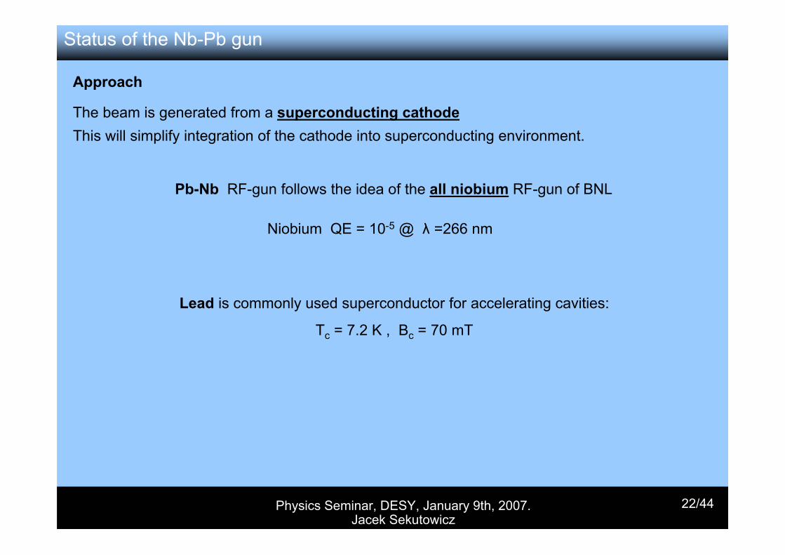
Approach
The beam is generated from a superconducting cathodeThis will simplify integration of the cathode into superconducting environment.
Pb-Nb RF-gun follows the idea of the all niobium RF-gun of BNL
Niobium QE = 10-5 @ λ =266 nm
Lead is commonly used superconductor for accelerating cavities:
Tc = 7.2 K , Bc = 70 mT
Status of the Nb-Pb gun
Physics Seminar, DESY, January 9th, 2007. Jacek Sekutowicz
23/44
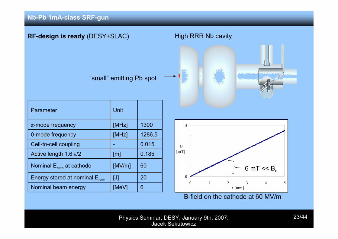
6[MeV]Nominal beam energy
20[J]Energy stored at nominal Ecath
60[MV/m]Nominal Ecath at cathode
0.185[m]Active length 1.6·λ/2
0.015-Cell-to-cell coupling
1286.5[MHz]0-mode frequency
1300[MHz]π-mode frequency
UnitParameter
“small” emitting Pb spot
High RRR Nb cavity
0
15
0 1 2 3 4 5 r [mm]
B [mT]
B-field on the cathode at 60 MV/m
6 mT << Bc
RF-design is ready (DESY+SLAC)
Nb-Pb 1mA-class SRF-gun
Physics Seminar, DESY, January 9th, 2007. Jacek Sekutowicz
24/44
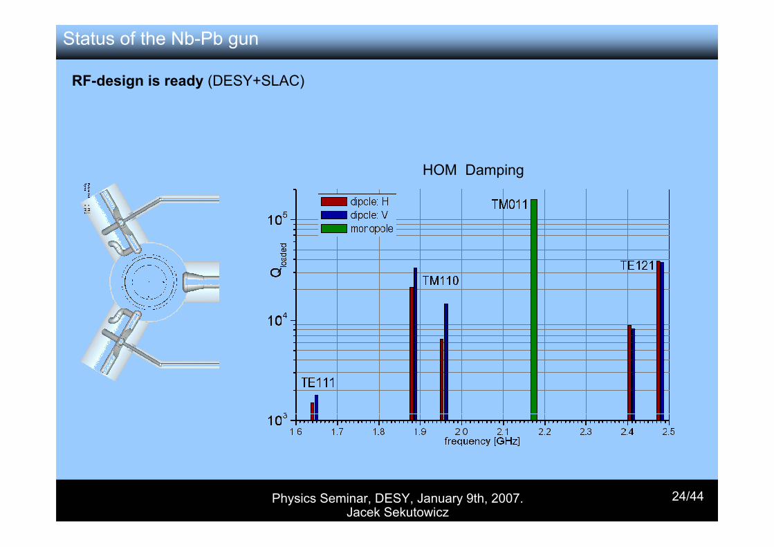
RF-design is ready (DESY+SLAC)
HOM Damping
Status of the Nb-Pb gun
Physics Seminar, DESY, January 9th, 2007. Jacek Sekutowicz
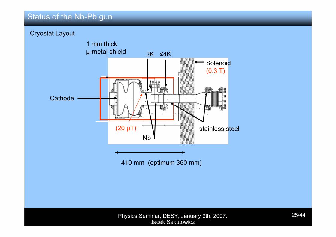
25/44
1 mm thick µ-metal shield
Solenoid (0.3 T)
stainless steelNb
Cathode
2K ≤4K
(20 µT)
410 mm (optimum 360 mm)
Status of the Nb-Pb gun
Cryostat Layout
Physics Seminar, DESY, January 9th, 2007. Jacek Sekutowicz
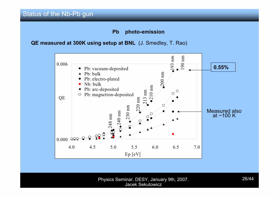
26/44
0.000
0.006
4.0 4.5 5.0 5.5 6.0 6.5 7.0
Pb: vacuum-depositedPb: bulkPb: electro-platedNb: bulkPb: arc-depositedPb: magnetron-deposited
190
nm
193
nm
200
nm
210
nm21
3 nm
220
nm
230
nm
240
nm
Ep [eV]
QE
248
nm
0.55%
QE measured at 300K using setup at BNL (J. Smedley, T. Rao)
Measured also at ~100 K
Pb photo-emission
Status of the Nb-Pb gun
Physics Seminar, DESY, January 9th, 2007. Jacek Sekutowicz
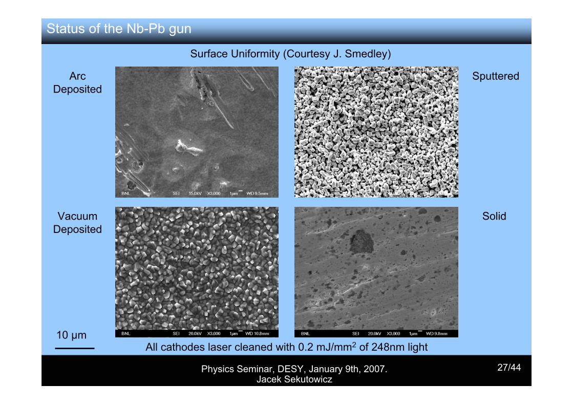
27/44
Surface Uniformity (Courtesy J. Smedley)
Arc Deposited
VacuumDeposited
Sputtered
Solid
All cathodes laser cleaned with 0.2 mJ/mm2 of 248nm light10 µm
Status of the Nb-Pb gun
Physics Seminar, DESY, January 9th, 2007. Jacek Sekutowicz
28/44
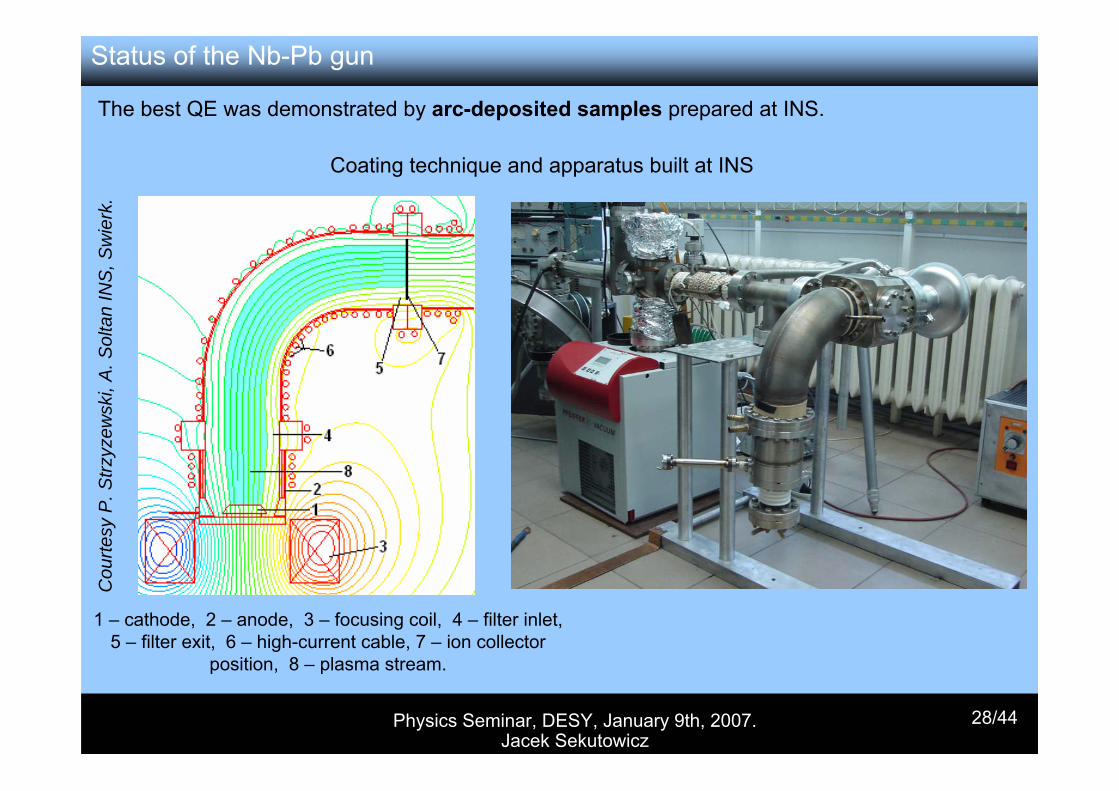
1 – cathode, 2 – anode, 3 – focusing coil, 4 – filter inlet, 5 – filter exit, 6 – high-current cable, 7 – ion collector
position, 8 – plasma stream.
Cou
rtesy
P. S
trzyz
ewsk
i, A
. Sol
tan
INS
, Sw
ierk
.The best QE was demonstrated by arc-deposited samples prepared at INS.
Coating technique and apparatus built at INS
Status of the Nb-Pb gun
Physics Seminar, DESY, January 9th, 2007. Jacek Sekutowicz
29/44
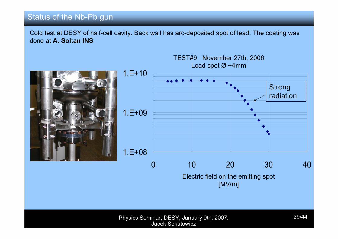
Cold test at DESY of half-cell cavity. Back wall has arc-deposited spot of lead. The coating was done at A. Soltan INS
Electric field on the emitting spot[MV/m]
1.E+08
1.E+09
1.E+10
0 10 20 30 40
TEST#9 November 27th, 2006Lead spot Ø ~4mm
Strong radiation
Status of the Nb-Pb gun
Physics Seminar, DESY, January 9th, 2007. Jacek Sekutowicz
30/44
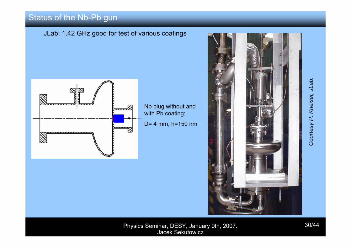
JLab; 1.42 GHz good for test of various coatings
Nb plug without and with Pb coating:
D= 4 mm, h=150 nm
Cou
rtesy
P. K
neis
el, J
Lab.
Status of the Nb-Pb gun
Physics Seminar, DESY, January 9th, 2007. Jacek Sekutowicz
31/44
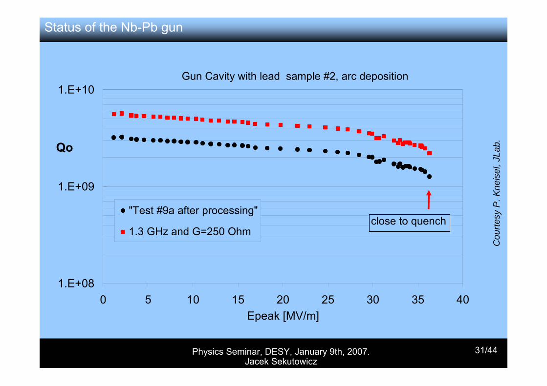
Gun Cavity with lead sample #2, arc deposition
1.E+08
1.E+09
1.E+10
0 5 10 15 20 25 30 35 40Epeak [MV/m]
Qo
"Test #9a after processing"
1.3 GHz and G=250 Ohmclose to quench
Cou
rtesy
P. K
neis
el, J
Lab.
Status of the Nb-Pb gun
Physics Seminar, DESY, January 9th, 2007. Jacek Sekutowicz
32/44
Future Plans
• One cavity with coated back plate has been shipped to JLab for RF and QE tests. Second cavity will be coated in January and after the inspection at DESY will be shipped to JLab in February.
• For the replaceable cathode cavity several Pb coated cathodes (sputtered and electro-deposited) will be tested.
• In collaboration with BNL, QE measurements will be carried out at cryogenic temperatures in a vertical Dewar at JLab. The measurements will be done on Pb .samples and on half-cell cavities with deposited emitting spot
• Relaxation time of Cooper pairs in Pb after the emitting spot is irradiated with the laser pulse
Status of the Nb-Pb gun
Physics Seminar, DESY, January 9th, 2007. Jacek Sekutowicz
33/44
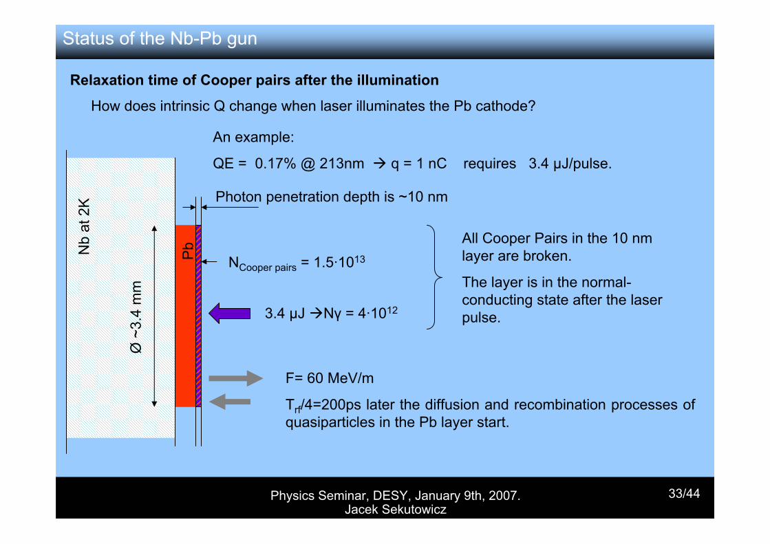
Relaxation time of Cooper pairs after the illumination
How does intrinsic Q change when laser illuminates the Pb cathode?
An example:
QE = 0.17% @ 213nm q = 1 nC requires 3.4 µJ/pulse.
Nb
at 2
K
Pb
F= 60 MeV/m
Trf/4=200ps later the diffusion and recombination processes of quasiparticles in the Pb layer start.
Photon penetration depth is ~10 nm
Ø ~
3.4
mm
3.4 µJ Nγ = 4·1012
NCooper pairs = 1.5·1013
All Cooper Pairs in the 10 nm layer are broken.
The layer is in the normal-conducting state after the laser pulse.
Status of the Nb-Pb gun
Physics Seminar, DESY, January 9th, 2007. Jacek Sekutowicz
34/44
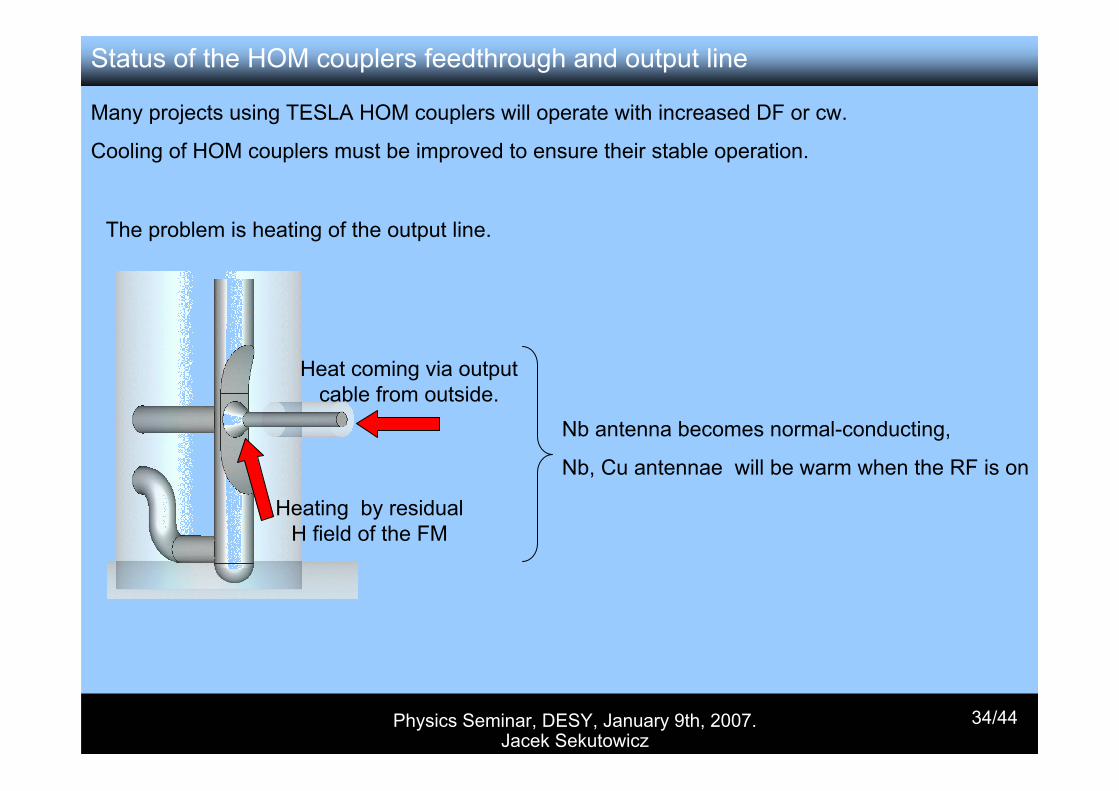
The problem is heating of the output line.
Heat coming via output cable from outside.
Heating by residual H field of the FM
Nb antenna becomes normal-conducting,
Nb, Cu antennae will be warm when the RF is on
Many projects using TESLA HOM couplers will operate with increased DF or cw.
Cooling of HOM couplers must be improved to ensure their stable operation.
Status of the HOM couplers feedthrough and output line
Physics Seminar, DESY, January 9th, 2007. Jacek Sekutowicz
35/44
Status of the HOM couplers feedthrough and output line
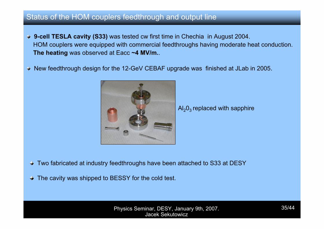
9-cell TESLA cavity (S33) was tested cw first time in Chechia in August 2004. HOM couplers were equipped with commercial feedthroughs having moderate heat conduction. The heating was observed at Eacc ~4 MV/m..
New feedthrough design for the 12-GeV CEBAF upgrade was finished at JLab in 2005.
Al203 replaced with sapphire
Two fabricated at industry feedthroughs have been attached to S33 at DESY
The cavity was shipped to BESSY for the cold test.
Physics Seminar, DESY, January 9th, 2007. Jacek Sekutowicz
36/44
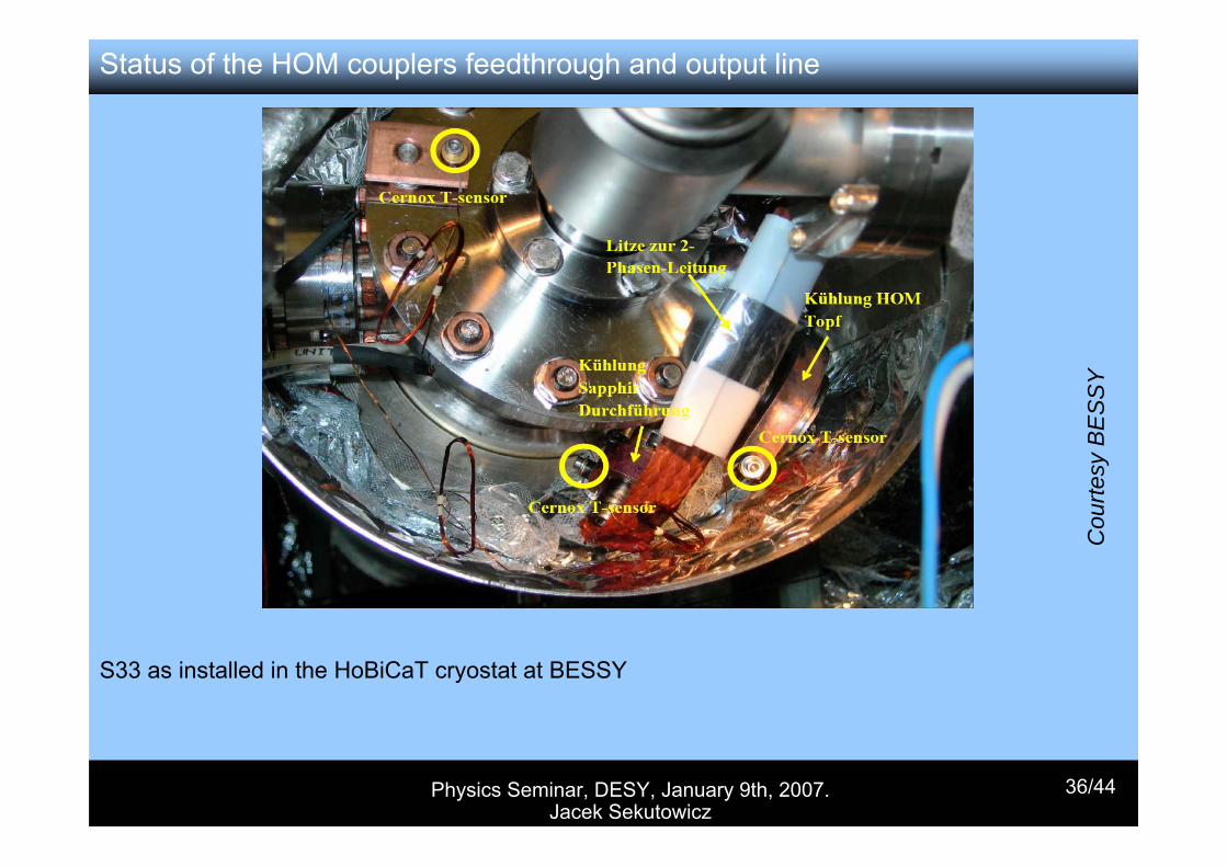
Status of the HOM couplers feedthrough and output line
S33 as installed in the HoBiCaT cryostat at BESSY
Cou
rtesy
BE
SS
Y
Physics Seminar, DESY, January 9th, 2007. Jacek Sekutowicz
37/44
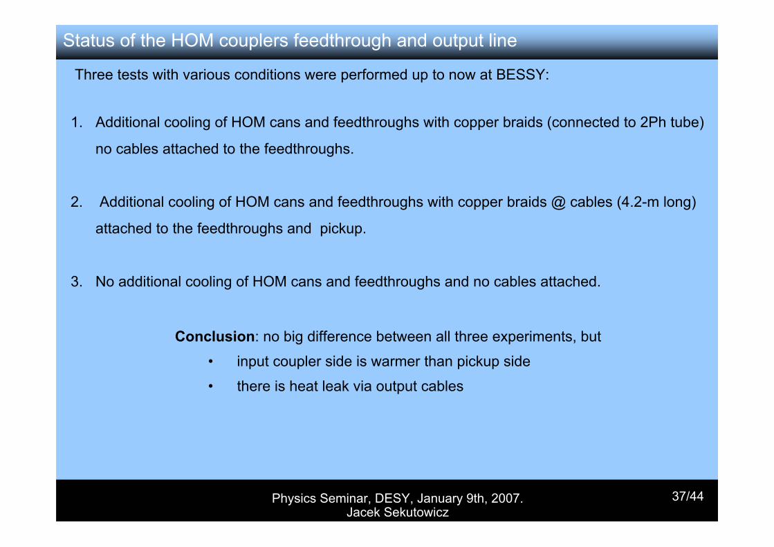
Three tests with various conditions were performed up to now at BESSY:
1. Additional cooling of HOM cans and feedthroughs with copper braids (connected to 2Ph tube)
no cables attached to the feedthroughs.
2. Additional cooling of HOM cans and feedthroughs with copper braids @ cables (4.2-m long)
attached to the feedthroughs and pickup.
3. No additional cooling of HOM cans and feedthroughs and no cables attached.
Status of the HOM couplers feedthrough and output line
Conclusion: no big difference between all three experiments, but
• input coupler side is warmer than pickup side
• there is heat leak via output cables
Physics Seminar, DESY, January 9th, 2007. Jacek Sekutowicz
38/44
Cou
rtesy
BE
SS
Y
Status of the HOM couplers feedthrough and output line
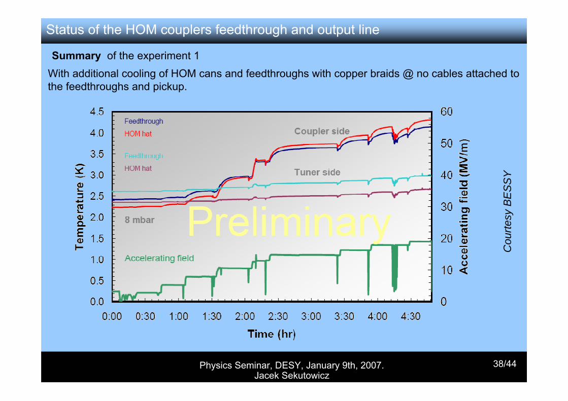
Summary of the experiment 1With additional cooling of HOM cans and feedthroughs with copper braids @ no cables attached to the feedthroughs and pickup.
Physics Seminar, DESY, January 9th, 2007. Jacek Sekutowicz
39/44
Cou
rtesy
BE
SS
Y
Status of the HOM couplers feedthrough and output line
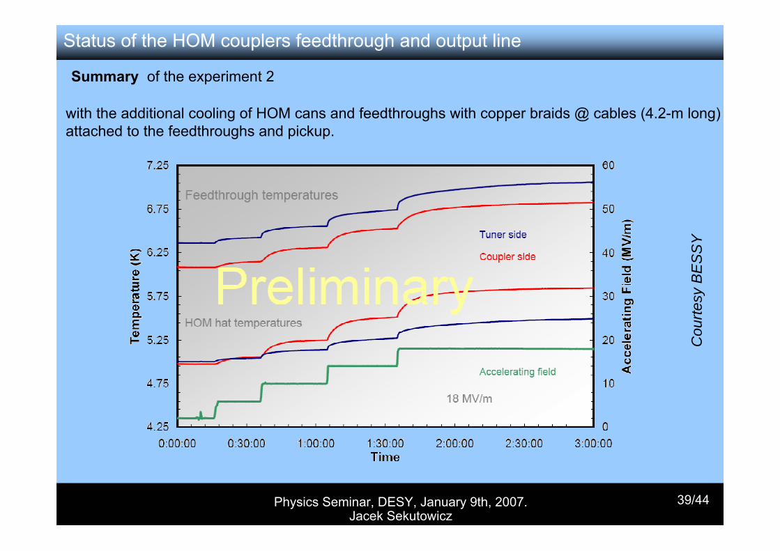
Summary of the experiment 2
with the additional cooling of HOM cans and feedthroughs with copper braids @ cables (4.2-m long) attached to the feedthroughs and pickup.
Physics Seminar, DESY, January 9th, 2007. Jacek Sekutowicz
40/44
Cou
rtesy
JLa
b
Status of the HOM couplers feedthrough and output line
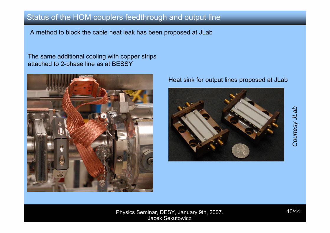
A method to block the cable heat leak has been proposed at JLab
The same additional cooling with copper strips attached to 2-phase line as at BESSY
Heat sink for output lines proposed at JLab
Physics Seminar, DESY, January 9th, 2007. Jacek Sekutowicz
41/44
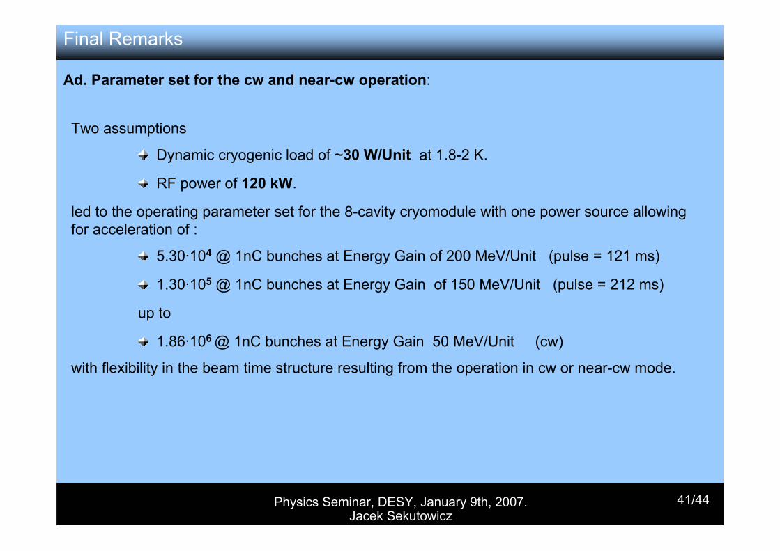
Two assumptions
Dynamic cryogenic load of ~30 W/Unit at 1.8-2 K.
RF power of 120 kW.
led to the operating parameter set for the 8-cavity cryomodule with one power source allowing for acceleration of :
5.30·104 @ 1nC bunches at Energy Gain of 200 MeV/Unit (pulse = 121 ms)
1.30·105 @ 1nC bunches at Energy Gain of 150 MeV/Unit (pulse = 212 ms)
up to
1.86·106 @ 1nC bunches at Energy Gain 50 MeV/Unit (cw)
with flexibility in the beam time structure resulting from the operation in cw or near-cw mode.
Final Remarks
Ad. Parameter set for the cw and near-cw operation:
Physics Seminar, DESY, January 9th, 2007. Jacek Sekutowicz
42/44
Final Remarks
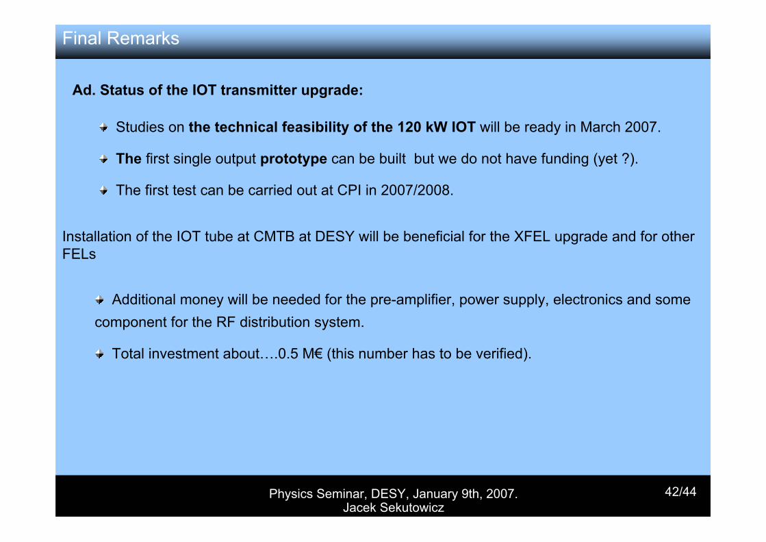
Ad. Status of the IOT transmitter upgrade:
Studies on the technical feasibility of the 120 kW IOT will be ready in March 2007.
The first single output prototype can be built but we do not have funding (yet ?).
The first test can be carried out at CPI in 2007/2008.
Installation of the IOT tube at CMTB at DESY will be beneficial for the XFEL upgrade and for other FELs
Additional money will be needed for the pre-amplifier, power supply, electronics and some component for the RF distribution system.
Total investment about….0.5 M€ (this number has to be verified).
Physics Seminar, DESY, January 9th, 2007. Jacek Sekutowicz
43/44
Final Remarks
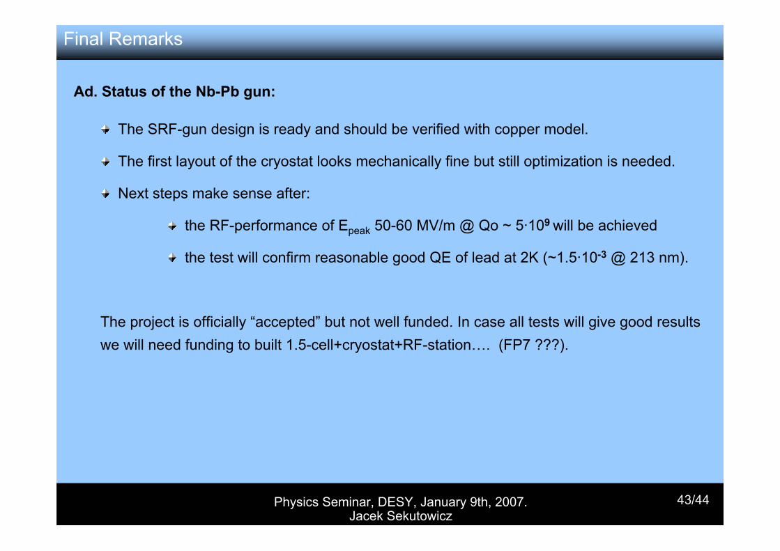
Ad. Status of the Nb-Pb gun:
The SRF-gun design is ready and should be verified with copper model.
The first layout of the cryostat looks mechanically fine but still optimization is needed.
Next steps make sense after:
the RF-performance of Epeak 50-60 MV/m @ Qo ~ 5·109 will be achieved
the test will confirm reasonable good QE of lead at 2K (~1.5·10-3 @ 213 nm).
The project is officially “accepted” but not well funded. In case all tests will give good results we will need funding to built 1.5-cell+cryostat+RF-station…. (FP7 ???).
Physics Seminar, DESY, January 9th, 2007. Jacek Sekutowicz
44/44
Final Remarks
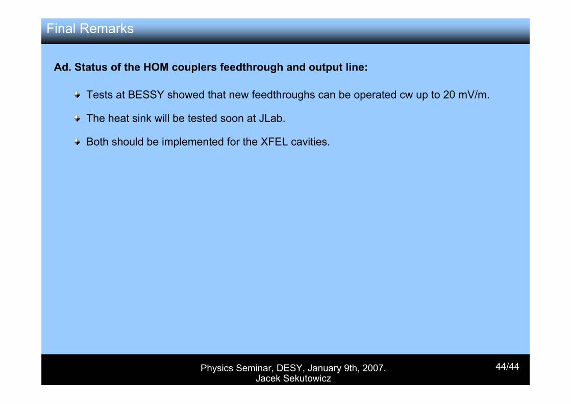
Ad. Status of the HOM couplers feedthrough and output line:
Tests at BESSY showed that new feedthroughs can be operated cw up to 20 mV/m.
The heat sink will be tested soon at JLab.
Both should be implemented for the XFEL cavities.