Embed Size (px)
Citation preview

CURRICULUM
T
351.5A321969
'.cr tttM*?
ALTA.2
GrlO-12
CURRGDHT CURR


N LIBRARYUi. Or. ALBERTA
CURRICULUM GUIDE
BDUCATION LIBRART
Senior High School
CURRICULUM GUIDE
Vocatioj
DpAFTTNP; 12 22 32
(Revised Edition)
Province of Alberta
Department of Education
September, 1969
CU
JBRAR7


ACKNOWLEDGEMENT
The Department acknowledges with appreciation the contributions of
the Ad Hoc Subcommittee on Drafting to this Curriculum Guide for
Drafting 12., 22, 32. The Ad Hoc Committee worked under the
guidance of the Secondary School Curriculum Board.
Mr. F. W. Appelt, Head, Drafting Department, N.A.I.T., Edmonton
Mr. K. II. Fawcett, Drafting Teacher , Victoria Composite High School.Edmonton
Mr. W. Greenwood. Drafting Teacher, Red Deer Vocational High School,Red Deer
Ilr. J. P. Haracsi. Drafting Teacher, St. Joseph High School; Edmonton
Mr. G. R. Howarth, Head. Drafting Department, S.A.I.T., Calgary
Mr. J. C. Smith, Drafting Teacher, Western Canada High School,Calgary
Mr. R. G. Taylor, Drafting Teacher , Bowness Composite High School.,
Calgary
Mr. R. H. Cunningham, High School Inspector of Vocational EducationDepartment of Education, (chairman)
NOTE: This is a service publication only. The official statement
concerning the course is contained in the High School Program
of Studies. The information contained in the Guide is
prescriptive insofar as it duplicates that given in the
Program of Studies. The Guide, however, contains, as well as
methods of developing the content, suggestions for the use of
teaching aids and additional reference books.


TABLE OF CONTENTS
page
Introduction
Objectives
General Information
Obj ectives for Drafting 12 5
Outline for Drafting 12 5
Objectives for Drafting 22 19
Outline for Drafting 22 19
Objectives for Drafting 32 47
Outline for Drafting 32 47


INTRODUCTION
This curriculum guide has been prepared for Alberta high schools
teaching vocational drafting.
Instructors of this subject should endeavor to follow this guide
closely in order to facilitate, as much as possible, Province-
wide standardization, thus enabling students to transfer from
centre to centre and continue with their course with a minimum
of adjustment.
It is hoped that this guide will prove to be of assistance and will
be used extensively by drafting instructors.

- 2 -
OBJECTIVES
The general objectives of the vocational drafting course are as
follows:
1. Prepare a student to a degree of competency acceptable
to the Institute of Technology and Art for entrance into their second
year of Drafting Technology or Architectual Technology Course.
2. Adequately prepare a student to the level where he will
be successfully employable in the drafting industry.
3. Supply those not necessarily interested in drafting as
a vocation, with enough skills so that they may use their knowledge
of drafting and blue print reading in one of the related fields.
4. To assist in developing the personality of the student
so that he will be a reliable, industrious, cooperative, socially
acceptable adult; and to retard any personal traits that would be
detrimental to the individual as an employee or fellow worker.
5. To assist the student in being able to read, appraise,
understand and use material written in a technical language.
6. To develop a systematic approach to solving problems
similar to the type likely to be found in industry.

- 3 -
GENERAL INFORMATION
1. Course Credit Values
Drafting 12 - 5 creditsDrafting 22 - 15 creditsDrafting 32 - 15 or 20 credits
NOTE: Drafting 22 includes 5 credits of machine shop and DraftDrafting 32 includes 5 credits of building construction.
2. Instructors ' Records
The instructor should keep accurate records of:
a. student enrolment and attendanceb. students' accountsc. student workd. theory taughte. tests givenf. student achievement
g. up-to-date inventory of all equipment
3. Students ' Records
Instructors should ensure that the student develops andmaintains a neat and accurate record of:
a. notes on theoryb. daily shop or drafting activities (time cards)
4. Guidance and Vocational Information
Instructors must assume responsibility in their trade areato ensure that students and school guidance officials are aware ofthe local situation. It is essential that the instructors be active,interested and informed regarding the opportunities in the trade.
NOTE : In order to permit students from an academic Grade X programto cross over into the vocational program at the Grade XIlevel, schools may combine the 12 and 22 courses into onecourse for a total of 20 credits. Where these courses arecombined it is recommended that students purchase the Grade XItext only .
NOTE ALSO : Whereas Drafting 12 is an exploratory course open to allGrade X students, the Drafting 22 and 32 courses are definite-ly vocational and only those students who have displayed abil-ity and aptitude for the program should be encouraged to con-tinue. It is not fair to the student to permit him to continuein a program which demands a large portion of his school time,and in which the instructor and/or the guidance counsellor feelthat he has little chance of success.
- 4 -
Instructions on the Use of the Guide
The pages of this guide are divided into three columnsmarked:, Basic Information, Operations and Projects, and References.The first colmun might be considered as detailed topics that must becovered by the instructor in class. The second column is a guide to
the student's activities. This covers explicit operations and skillsthat the student must master. The third column refers to places in
various reference books that the instructor should become familiarwith in order to successfully present the required information. Thesebooks are recommended for drafting room reference.
CODE FOR REFERENCES
C.S.A. Canadian Standards Association. Mechanical EngineeringDrawing Standards . Latest edition. B78.1
C.G.S.B. Canadian Government Specifications Board. ArchitecturalDrawing Practices . 33-GP-7.
F V French, Thomas E. and C. 'T. Vierk. Engineering Drawing .
9th edition. Toronto: McGraw-Hill of Canada, 1960.
F S French, Thomas E. and Carl L. Svenson. Mechanical Drawingand problem sheets (Levens and Edstram, Pts. 1 and 2),Toronto: McGraw-Hill of Canada, 1966.
G Giesecke, Frederick E. et al. Technical Drawing . 5th ed.Gait, Ontario: Macmillan Company, 1967.
Y Yankee, H. W. Machine Drafting . Toronto: McGraw-Hill ofCanada, 1966 edition.
Z Zozzora, Frank. Engineering Drawing . Toronto: McGraw-Hill of Canada, 1958.
In the event of conflict between texts, the C.S.A. andC.G.S.B. manuals will be the final authority.
The projects that are listed are to be used merely as aguide to present some standard of accomplishment throughout theprovince. Individual instructors may select other projects of similarnature, but that would demand an equal effort from the student asthose suggested in the guide.

- 5 -
OBJECTIVES FOR DRAFTING 12
The first year should be considered to be an exploratory yearduring which the students investigate drafting generally. This shouldenable them to make an informed decision about further study ofDraft ing
.
The more specific objectives for the Grade Ten or first yearare as follows:
1. To create a desire for proficience and accuracy in bothdrafting and related theory.
2. Develop habits of neatness, cleanliness and orderlinessin work situations
.
3. Become aware of positions and employment opportunitiesin the drafting industry.
4. Understand the importance of drafting, related technicalskills and knowledge in an industrial nation.
DRAFTING 12(130 Hours)
TEXT: Jenson. C. H. and F. H. Mason. Drafting Fundamentals. 2ndedition. Toronto: McGraw-Hill of Canada.
Basic Information Operations and Projects References
Unit 1: Introduction
General class organi- Students should begin Text Chptr 1
zation, issuing of notebook with place for F.S. Chptr 1
supplies and equipment. Glossary of terms.Introduction of draft-ing as the language ofthe industrial andtechnical world. Over-view of course andstandards expected.

- 6 -
Basic Information Operations and Projects References
Unit 11: Instruments and Materials
Introduction to thetools ; compasses
,
dividers , spring bows
,
T-square, set squares(30 -60 -45 ), scales,erasers , erasingshields, sandingblock, drafting tape
3
drawing papers, etc.Care and storage ofequipment . Boardrequirements . Fasten-ing paper to board.Construction and useof T-square, test for aaccuracy. Methods ofsharpening pencils,correct method ofdrawing lines, etc.Use of protractor,compass, dividers,scale (1/16 inchdivisions), architects'scales, erasing shield,etc. Alphabet of lines,sizes of drawings (ASA)
Stress correct use ofinstruments. Mountingpaper, border, title,
block, etc. Horizontallines, verticle lines,angles of 15 multiplesusing both triangles.Drawing parallel lineswith set squares . Divid-ing a line or space byparallel line method.Drawing of differenttypes of lines , circles
,
arcs, tangents.Construction lines,center lines , hiddenlines, outlines, orderof drawing and darkening.Suggested projects:G - P. 60 rig. 94
P. 61 Fig 96 or someof Fig. 97
P. 62 Fig. 99
Text Chptr II
F.S. Chptr II
Unit III: Lettering
Importance of letteringin drafting. Forms ofAlphabets and their use.Caps and lower case
.
Compressed, normal andextended lettering.General proportions,order of strokes andcomposition. Letteringmust be taught andchecked all during theyear.
Single stroke uppercase Gothic lettering.Students become profi-cient with 1/8", l/4 ;
and 3/8 K lettering,centering of titles andtitle blocks, etc.Lettering on the faceof drawings shall be1/8' vertical, singlestroke Gothic.Suggested projects :
2 plates 81/2 x 11 to
Text Chptr II
G. Chptr IIIF.S. Chptr III

- 7 -
Basic Information Operations and Projects References
include alphabets
,
numerals, fractions,words, phrases, etc.
in three sizes 1/8',
1/4' and 3/8 .
Vertical single strokeGothic.
Unit IV: Geometrical Construction
Terms; points, lines,
angles , triangles
,
quadrilaterals, poly-gons , circles , arcs
,
tangents, etc. The
draftsman's method ofdrawing these shouldbe demonstrated and
stressed.
Applications ofgeometric construction
Bisection of a line.
Bisection of an arc.
Bisection of an angle.Construction of a line
through a point parallelto a given line.
Construction of a line
parallel to a given line
at a given distance fromit.
^he division of a lineinto equal parts
.
The construction of aline through a point per-
pendicular to a givenline.The construction of a
triangle with givensides.The construction of asquare.The construction of a
hexagon across cornersand across flats.The construction of a
circle through threepoints not in a straightline.The construction of a
circle tangent to a lineat a given point
.
The construction oftangent arcs
:
- to two lines at rightangles
.
Text Chptr III
G. Chptr IV
F.S. Chptr IV

- 8 -
Basic Information Operations and Projects References
to two lines at acuteor obtuse angles.
to an arc and a straightline.
Unit V: The Theory of Projection Drawing
This should be consider- Text Chptr IVed as an introductory G. p. 9
unit, stressing 'che (see chart)following: F.S. Chptr V
A. Drawings arenecessary in the indus-trial world to record,express and convey ideasand information, neces-sary for the construc-tion and erection ofmachines and structures.
B. There are differentmethods of drawing therepresentation of anobject.
C. It is difficult todraw things accuratelyand at the same timemake them appear as realobjects.
D. Standard ways ofrepresenting objectsare necessary for uni-versal understandingof the representation.The instruction shouldshow examples of
:
1. Single pointperspective
.
2. Two pointperspective.3. Three pointperspective.

- 9 -
Basic Information Operations and Projects References
4. Isometric.5. Cabinet.6. Cavalier.7. Orthographic.
This section is to leadup to the next unit
\
orthographic projection,
Unit VI : Orthographic Projection
A. Introduction—or-thographic true shape.
B. Views of an objectsglass box; arrangementof views. The C.S.A.
layout of views one
,
two, and three viewdrawings. (Familiarwith alternate viewdrawings, position ofviews, partial views.)How to balance 2 viewdrawing and 3 viewdrawing
.
C. Hidden lines, themeaning of lines , theprecedence of lines.
D. Transferring depthmeasurements
.
E. Visualization-inter-pretation of views.
F. Surfaces, edges,corners , normal surfacesand edges , inclinedsurfaces , obliquesurfaces
.
Laying out and drawingof simple two and threeview drawings . Theinstructor should selectsuitable objects orprojects out.The instructor may alsouse self devised blocksand job sheets for bettervisualization by thestudents.Drawings of objects maybe selected from G. 6 F.S.The instructor shouldalways keep in mindstudent interest whenselecting the drawingsto be drawn by the studentcovering all the fore-mentioned points underBasic Information.Sketching should be
included as project work.
Text Chptr IV
G. Chptr VI
F.S. Chptr Vand VII
G . Scale drawings
.

- 10 -
Basic Information Operations and Projects References
H. Orthographicsketching.
(See Unit XI)
Unit VII: Dimensioning
Introduction
:
1. Size description.2
.
Scale of drawings
.
3. Lines used in
dimensioning.4. Placement ofdimension and exten-sion line.5
.
Arrowheads andleaders
.
6. Fractional anddecimal dimensioning.7. The lettering andreading of dimension-al figures
.
8. Symbols for feetand inches.9. Dimensioning,angles , arcs , fillets
,
and rounds
.
10. Size and locationand dimensioning.
Dimensioning problemsfrom the text.Problem sheets - couldbe made up and have thepupils place the properdimensions
.
The previous units canbe dimensioned, afterall the factors indimensioning have beencovered.
Text Chptr VI
Unit VIII: Isometric Drawing
Isometric drawing.1. The position ofisometric axes
.
2. Offset locationmeasurements
.
3. Hidden lines inisometric drawings
.
4. Centre lines.5. Box construction6. Non-isometriclines.
7. Isometric
Students should draw anumber of simple iso-metric drawings
.
The instructor whenselecting drawings,should always keep inmind the points underBasic Information andstudent interest
.
Sketching should beincluded as projectwork.
Text Chptr XG. Chptr XVIIF.S. Chptr XIV

- 11 -
Basic Information Operations and Projects References
dimensioning,8. The use of iso-metric drawings in
industries
.
Unit IX: Oblique Projection
A. Types of oblique Text Chptr X
projection G. Chptr XVII1. Cabinet projection. F.S. Chptr2. Cavalier. XIV
B. The Choice of positionof the object.C. The steps followed.D. Dimensioning anoblique drawing.E. Sketching in oblique.
NOTE: Students should make drawings of the sameobject by e?ch of the methods of obliqueprojection.
Unit X: Technical Sketching
A. Value of technical Sketching may be Text Chptr II
sketching. applied in all units. F.S. Chptr VI
1. A means ofexpression of ideasthat are difficult toput into words.2. A simple and quickmeans of expressing an
idea (Thinking with apencil)
.
B. Sketching meterials. G. p. 1301. Pencil H, HB. M. p. 10-112. Eraser Z. p. 42
3. Papery plain white,squared
9isometric
,
thin paper placed overdark lined squared orisometric paper.

- 12 -
Basic Information Operations and Projects References
C. Line technique.1. Outline.2. Dimension line.
3. Invisible line.
Draw several drawingsrequiring various types
of lines . It would be
desirable to use severalof the types of paperlisted in column one.
D. Proportions
E . Circles , arcs andellipses.
1. Blocking in circles2
.
Use of radial lines
,
3. Use of squaredpaper to draw circles.4. Isometric paper andellipses.
Proportion and line
techniques should be stressed.
One exercise in freehanddrawing of curved linescircles and ellipses.Hake use of modelsavailable in the class-room. Students couldmake sketches of manyof the drawings theywill complete at a
later date.
F.S. Chptr VI
Unit XI : Primary Auxiliary Views
A. Primary auxiliaryview.
1. This is a viewprojected to a planeperpendicular to oneof the three principalplanes ; front , top orside and inclined tothe other two.
B. How to draw an auxi-liary view.
1. How to draw areference lineparallel to the edgeof a view. The ref-erence line can beconsidered a foldingline.2. The reference lineis used to locatepoints on the auxi-liary view.
Text Chptr IX
Use classroom models assamples for auxiliaryviews
.

- 18 -
Basic Information Operations and Projects References
3. The convenienceand accuracy gainedwhen the referenceline is passed througha plane or points ofthe object itself.
C. Construction of auxi-
liary views, (simpleobjects)
1. Procedure forsimple auxiliaryviews
.
D. Partial auxiliaryviews
.
1. The practice ofshowing only the shape
and details of theinclined surface andnot a view of the
entire surface.
E. Auxiliary view tocomplete a principalview.A situation is oftenencountered where an
auxiliary view is
necessary to completeother views
.
1. Know the proce-dure of showing theinclined plane as an
edge to construct a
principal view.
Keep the projects simple,
F. True length of line1. True length ofline seen only on a
plane of projection.
Unit XII: Sections
A. Visualizing asection.

- 14 -
Basic Information Operations and Projects References
1. Make use ofdrawing in text
.
2. Use mockups madeof wood.
Cutting plane.1. A portion of anobject nearest theobserver that has
been removed by meansof a cutting plane toreveal section linesand arrows.
Draw a simple sectionfrom a model or fromexamples
.
C. Section lining.1. A method ofdistinguishingsections by lining.2. The drawing ofparallel lines acrosjall surfaces cut.
Draw a simple fullsection. Examples maybe a section of pipe,bearing or flange
.
Students should doseveral simple drawingsto develop some skill.One drawing should beof such a nature thatspecial angle linesneed be used.
D. Section liningtechniques
.
1. Proper line anglefor good contrast
.
2. Use of symbolicsection lining.
E. Kinds of sections.1. Full sectionsA longitudinal lineextending through anentire object.2. Half.A symmetrical objectdrawn so that onlyhalf of it is sec-tioned. One side ofthe centre line only.3. Offset sections.Placing the cutting
A simple drawing thatmust be lined at aspecial angle.Include a drawing linedto indicate material.This could be a drawingof standards used, etc.
If time permits :
One simple drawing thatcould contain several ofthese sections.
Text Chptr VIII

- 15 -
Basic Information Operations and Projects References
line through otherthan the main axis sothat it shows directfeatures and details.
If time permits :
4. Broken out.
A section drawn notindicating the cuttingplane used only toshow some isolateddetail.5 . Removed
.
Sections drawn similarto revolved except theyare placed outside or
at one side of thedrawing
.
6
.
Revolved
.
The imaginary cuttingplane is passed throughthe object perpendicularto the horizontal axisand revolved on its
centre 90 into thepaper.
Show on^ isolatedsection of one of theabove drawings
.
One of the above draw-ings might be repeatedto show the revolvedsection more clearly.
G. p. 217
F. Breaks and ribs in
sections
.
1. When cuttingplane cuts flatwisethrough a web geartooth or flat element;a false impression ofsolidity should be
avoided.2. The flat rib shouldnot be sectioned.
Any one of the abovedrawings could containa rib or webb.
Unit XIII: Reproduction of Drawings
A. Tracing media.1. The selection oftracing papers
.
2. Test the abilityof the paper to take
Students should be ableto observe the transpar-encies of the variouspapers . A demonstrationwith various papers would
Text Chptr VI
F.S. Chptr VIII

- 16 -
Basic Information Operations and Projects References
ink, pencil, erasing,re-inking, smooth orrough line, etc.3. Tendancy of paperto discolor and becomebrittle.4 . Tracing cloth andits use because ofdurability and perma-nency. Good for inkand pencil. Shiny anddull side. PolyesterBase Films.
be excellent, pointingout the value of ragcontent
.
Demonstration
B
.
Reproductions
.
C. Diazo prints (whiteprints)A process based on light-sensitive diazo compounds.Advantages of thisprinting process
D. Reproduction quality.1. Demonstration andlecture of what to lookfor in good prints
.
2
.
Recognize poorprints due to poortracings, paper quality,over and under exposure.
Students should do at
least one print usingthis process if equip-ment is available.
Unit XIV: Drawing Interpretation
The term applies to thereading of the languagefrom the drawings ofothers. The studentsshould be able tointerpret the ideasexpressed on technicaldrawings
.
Have the student reador interpret drawingsfrom the files or text
.
This could be in theform of a writtenassignment
.
Ask for some oral inter-pretation for confirmationof students understanding.Have students study fellow
Text Chptrs.XII & XIII

- 17 -
Basic Information Operations and Projects References
students J drawings orspecial file drawings co
observe errors that havebeen made
.
Unit XV: Employment Opportunities
The place of drafting in
industry. Comparisonof incomes—opportunitiesfor advancement . Relatedoccupations. Stability ofthe job. Hours of work.Training and costs
.
Employment opportunities.


- 19 -
OBJECTIVES FOR DRAFTING 22
1. To develop in the student an appreciation of craftsman-ship in the field of drafting and promote a desire to attain a highdegree of drafting skill and understanding.
2. To develop the ability to work in an orderly and effi-cient manner.
3. To develop skills in lettering, mechanical drawing andsketching.
4. To provide practical knowledge and experience in thefield of metalworking.
Drafting 22 consists of: Part One - Drafting - 10 creditsPart Two - Metalworking - 5 credits
The number of hours to be devoted to each unit are indicatedat the beginning of the unit . These are to be used as a guide inapportioning the time available so as to assure that all units arecovered and in the same depth that the allotted time permits.
DRAFTING 22
(3S0 hours - total)
PART ONE
TEXTS: Giesecke, Frederick E. et al. Mechanical Drawing . 5th ed.
Toronto: McGraw-Hill Book Company.
Yankee , Herbert W . Machine Drafting and Related Technology ,
Toronto: McGraw-Hill Book Company.
NOTE: Unit VIII 'dimensioning' 1 is applicable to most other unitsand should be taught in conjunction with them.
Basic Information Operations and Projects References
Unit I : Lettering - 9 hours
A. Gothic capitals, Use of cross-section F.S. Chptrnumerals and fractions. paper or ruled squares III
Freehand. Vertical. (Perhaps 1/2 1 or 3/4 r
) G. Chptr III

- 20 -
Basic Information Operations and Projects References
1. Form and propor-tion.2
.
Order of strokes
,
3. Uniformity in form,slope, height andstroke. Strokes dark,sharp, definite and ofapproved width.
4. Fractions. Heightsof fraction in relationto whole number.Fraction bar is notoblique. Figures donot touch fraction bar.5. Spacing lettersand words
.
6. Simple titles andtitle blocks.
7. Meaning.of "light-face 11 and "boldface !i
lettering.
8. Compressed andextended letters.
for practice in formingletters of proper Gothicform, correct height in
relation to width, andapproved sequence ofstrokes. Use C.S.A.alphabet
.
Lettering practice.Use thin faint guidelines for 1/4" and l/8 :;
letters and numerals
.
Students should havelettering instrumentsto make guide lines
.
Practice for height andproportion in fractionsand proper placementand alignment offraction bar.
Lettering words andsentences 3/8" , 1/4"1/8 • high. Stress theimportance of carefuland extensive practice.Learn and apply methodsof centering words andphrases through practiceexercises. A suggestedassignment is the design-ing of a title page fordrafting notes andassignments. Applylettering practice tosimple title blocks ortitle strips and deviseone suitable for mostof the drawings
.
Return to short letter-ing practice exercisesduring the term. Laterassignments shouldinclude informationand practice in apply-ing "lightface" and"boldface" lettering,and compressed andextended letters.
C.S.A.
CSA B78.1

- 21 -
Basic Information Operations and Projects References
9. Lettering with ink.
10. Mechanical letter-ing devices
.
Speedball, rapidographmapping.
Unit II: Instruments and Materials - 8 hours
Scales1. Types—discussand demonstrate thethree basic types(Architect, MechanicalEngineer, and CivilEngineer) with theuses of each.2. Use of CommonlyAccepted Scales
.
These are
:
a. Architect:1/8" - l»-0"1/4" - l'-0"
G. Chptr II
Z. Chptr IVF.S. Chptr II
Scale a number of givenlines using the varioustypes of scales when thelines are drawn tovarious scales.
3/4" - l'-0" Draw a number of linesll/2 r: - l'-0' T of given length to3" - l'-0" various scales.
b. Mechanical:Engineer
:
full size Start with full sizehalf size scale and introducequarter size others
.
eighth sizec. Civil Engineer:
10
20
40
50
3 . Scale shapes andmaterials
:
a. triangularb. flat-single bevelc. flat-double beveld. box woode. box wood withplastic facingf . all plastic

- 22 -
Basic Information Operations and Projects References
4. Methods of divi-sion:
a. open dividedb. close (or chain)divided
B. Pencils.1. Hardness andgrade from 7B (soft-est) to 9H (hardest).
2. Quality-draftingpencils generally-
high quality.3. Composition-stan-dard pencil (graphiteand clay); combinationof graphite and plastic;all plastic. Whereused.4. Points and sharp-ening. Sharpeningwith draftsman'ssharpener. Shapingconical and chiselpoint and screw driver.5. Mechanical pencils--point out availability,construction, grades oflead.
Students should purchasesoft, medium and hardpencils. Other gradescan be circulated in theclass if desired.
Demonstrate advantages anddisadvantages of variouscompositions of pencil onvarious surfaces.
Demonstrate sharpeningprocedure and insurethroughout the coursethat students keeppencils sharp and clean,
C. Compasses.1. Adjusting andusing compass.2. Adjusting andusing bow instruments.3. The drop compass.4. The beam compass.5. Sharpening thelead.
6. Adjusting and careof the pen.
D. Dividers.1. Types and uses.2. Adjustment.3. Transferringlengths.
Draw 1 plate of circlesof specified sizes.
Demonstrate correctoperations carefully.Divide given lines andarcs into equal spaces.Transfer measurements

- 23 -
Basic Information Operations and Projects References
4. Dividing lengths.
E. Parallel RuslingDevices.
1. T-square—materials(wood, plastic, metal,individual and in
combination); testingof; care of; correctuse.
2. Parallel rule,(cable type) testingof; care of; correctuse.3. Drafting machines.Types (band, parallel-ogram, rail mounted);adj ustment s ; care
;
correct use.4. Straight edges
—
types and uses.5. Triangles, fixed.Shapes (2 basic)
;
materials (wood,
metal, plastic) test-ing, trueing, use of.
6. Adjustable tri-angles — advantagesand disadvantages,use of.
from one simple drawingto another in combinationwith T-square andtriangle practice.Students should startwith problems involvingT-square and triangles,then advance to combi-nation with 'caseinstruments 1,
.
G. Chptr II
Z. Chptr IV
Suitable projects maybe found in all refer-ence books.
F. Irregular and flexi-ble curves.
1. Irregular (French)curves—types; uses of.
2. Flexible curves
—
two main types—adjust-able curve and spline.
Practice may be includedin an assignment includ-ing plotting of ellipsesof other non-circularcurves; graphs, etc.
Protractors1. Materials used,shapes (semi-circularor circular); plainor vernier.2. Used to lay outangle
.
Measure angles on aproblem sheet.
Layout angles
.

- 24 -
Basic Information Operations and Projects' References
3. Used to measureangle
.
H. Paper types and uses1 . Drawing papers
,
HP, CP: and R and
their uses for penciland water color work.
2. "Natural' tracingpapers of variousgrades.3. "Prepared 1 ' tracingpapers of variousgrades
.
4. Special drawingmedia, cloth, film, etc,
I. Drawing boards andcovers
.
1. Drawing boards
—
materials in order ofpreference: construc-tion: true edge: careof.
2. Drawing boardcovers—plasticizedpaper • drawing paper
;
linoleum; plasticlaminate. Point outthe advantages anddisadvantages of each.
Erasing devices.1. Hand erasers
—
point out damagecaused by hard, grittyerasers. Pink erasersfor erasing of linework.
Examine and draw on
various types andgrades of papers.In compliance withindustrial practicehowever, most assign-ments throughout theyear should be com-pleted on tracing paper,
Examine the boardsavailable to thestudents. Point outgood and bad featuresand have them checkout their boards fortrueness of edge, etc.Demonstrate as manytypes as possible. It
would be advantageousif each of the severalcovers is provided onseveral boards whichcan be used by thestudents.
Early practice in thecorrect use of thevarious erasers andaids is desirable,before an advanceddrawing is torn orspoiled due to lackof proper instruction.

- 25 -
Basic Information Operations and Projects References
2. Erasing shields
—
advantage of metal overplastic; correct use.3. Electric erasingmachines—care in theuse of
K. Drawing inks.
1. Black and color2. Types and qualities.
Unit III: Geometrical Constructions - 28 hours
A. Draftsman's methods Review problems G. Chptr IV
applied to geometry. previously studied Z. Chptr V
in Drafting 12.
B. The function ofgeometrical construc-tions in solvingdrafting problems.The mathematical reasoningin relation to problems e.g.
tangents in relation toarcs and ellipses, theellipse as a conicsection, loci;, termsand definitions.The importance of theseconstructions in developingskill and precision in
the use of instrumentsand sharp pencils. Theapplication in a techni-cal sense of these con-structions.
C. Geometrical Drawing assignmentsconstructions: involving the new
1. Tangent arcs constructions listed.a. arc tangent totwo arcsb. series of arcsjoined at tangentsforming a curve

- 26 -
Basic Information Operations and Projects References
c. a tangent to a
circle through a
given point- on the circle- outside the circle
2
.
Ogee curve
.
3. To rectify an arc.4. Ellipse - trammeland concentric circlemethod. Four centreapproximate foci andparallelogram method.5. Helix.6. Pentagon7
.
Octagon8. Constructionnecessary to findcentre of a circle.9
.
The constructionof a regular hexagongiven
:
a. the circum-scribed circle.b. the inscribedcircle.
c. the distanceacross corners.d. the distanceacross flats.e. one side ofthe hexagon.
10. Measurement ofa given length alonga given arc.
Drawing assignments and/
or job sheets applyingthese constructions toproblems - e.g. geomet-rical figures, arches,"instrument panels 1 ',
and "gaskets' 1
.
Unit IV: Theory of Projection - 3 hours
This section deals withprojection systems andtheir relation to eachother. Individualsystems of projectionand their resultingdrawings will be takenseparately and in a

- 27 -
Basic Information Operations and Projects References
detailed manner laterin the course.There are two classi-fications of projectivesystems
:
Perspective or centralprojection and Parallelprojection.
A. Perspective1. The eye of theobserver is at a
finite distance fromthe object.2. Projectors con-verge to a stationpo int
.
3. Projectors piercethe picture planeat varying angles
.
*+. Types of linearperspective:
a. one poirt(parallel)b. two point(angular)c. three point(oblique)
The instructor shouldnot attempt to teachthe theory of perspec-tive or the method ofprojecting a perspectivebut should sketch simpleobjects using one andtwo vanishing points
.
He could show samples
of the various kinds ofperspectives teachingrecognition of thesetypes
.
B. Parallel projection.1. The eye of theobserver is at an
G. p. 9
see chart
This information shouldbe made up in their notescomplete with diagramsof a simple object such
as a box, cube, etc.,drawn in the three typesof perspective.
Students are not expectedto make perspectivedrawings at this time.
F.S. ChptrXIV
The information given bythe instructor should be

- 28 -
Basic Information Operations and Projects References
infinite distancefrom the object.
2. The projectorsdo not converge butare parallel.3. The projectorspierce the pictureplane at the sameangle
.
4. Types ofparallel projection,
a
.
orthographici. multiview
ii . axonometric- isometric- dimetric- trimetric
b. obliquei. cabinet
ii. cavalier
included in the student '
s
notes , complete withdrawings of simple objectsillustrating the kinds ofparallel projection.They should also make a
sketch or chart of theprojective systems similarto that shown in Giesecke,page 9 , showing therelationship betweensystems
.
Note : Industriallyaccepted classificationimplies that ortho-graphic means multiviewand that others arepictorial.
Unit V: Multiview Orthographic Projection - 21 hours
Third angle
A. Definition of ortho-graphic projection (seeF.S. p. 64, 5.6)
Memorize definition F.S. Chptr V
(page 66)
B. Planes of projection1. Horizontal2
.
Frontal3. Profile
G. Chptr VI
F.S. Chptr V
and VII
C. Projectors are per-pendicular to planesof projection.
D. 'Glass box' 1 suppliesprinciple.
E. C.S.A. (A.S.A.)arrangement of views
Notes , completewith sketches.
G. Chptr V
and VI

- 29 -
Basic Information Operations and Projects References
F. Alternate position(civil)
G. Principle of thirdangle projection - 4
quadrants
.
H. Representation oflines.
1. Edge view.
2
.
Inters ect ion
.
3
.
Surface limit
.
I. Classification oflines and surfaces.
1
.
Normal surfaces
.
2
.
Normal edges
.
3. Inclined surfaces4. Inclined edges.5. Oblique surfaces.6. Oblique edges.
7
.
Parallel edges
.
8
.
Curved surfaces
.
a. single curved.b. double curved.
F.S. Chptr V
Z. Chptr II
Notes and drawings ofvery simple objects toillustrate these surfacesand edges as shown onthe drawing.
J. Line characteristics,1. Constructionlines (with hardpencil)2
.
Centre lines
.
3. Object lines.4. Hidden lines.
K. Precedence of lines.
L. The three spacedimensions.
1. Height.2
.
Width
.
3. Depth.
M. Selection of views.
N. Spacing of views,(paper sizes based oncommercial letterheadsize of 81/2 x 11).
The student could drawsamples of these linesor they could be incor-porated into a drawingof a simple object.They should master thetechniques of drawinggood lines before pro-ceeding to more diffi-cult drawings.Notes.
Notes and exercises.
Notes and a simpledrawing using onemethod of spacing.
G. Chptr II
Z. Chptr III
F.S. Chptr V
Chptr V
and VI
F.S. Chptr V

- 30 -
Basic Information Operations and Projects References
0. Projecting theviews
.
1. Use of projectors2
.
Transferringmeasurements
.
a. with dividers.b. by use of mitreline.
c. swinging arcswith compass
.
d. with scale.3. Projecting anelliptical boundary.4. Projecting acurved boundary.5. Fillets, rounds,and runouts
.
Fundamentals i.e. lay-out, accuracy, neatness,correct line weights,lettering, etc. must bestressed at all times.It is felt that a largenumber of simple drawingsgradually becoming moredifficult is more usefulthan a few laboriousdrawings. The abcve tobe followed by a minimumof three drawings ofactual objects.
P. Order of drawing.
Q. Multiview drawings(first angle).
1. Theory behindfirst angle.2. Quadrant used.
3. Where this kindof projection is used
Notes, etc.
It is desired thatstudents have a
knowledge of thismethod only.
Z. Chptr II
G. Chptr VI
Unit VI: Sections and Conventional Practices - 28 hours
A. Definition.
B. Cutting plane andline.
C. Full section.
D. Half section.
E. Offset section.
F. Removed section.
Study complete chapter. F.S. p. 98, 8.2
F. p. 216,8.3 - 8.8
G.p.213, 250-
253, 255

- 31 -
Basic Information Operations and Projects References
G. Revolved section.
H. Aligned section.
I. Broken out section.
J. Assembly section.1. Mechanical2. Building detail.
K. Section liningtechnique thin materials— outline sectioning,etc.
L. Conventionalpractices
.
1. Ribs, spokes,
lugs, etc. in
section.2. Alternate crosshatching.3. Aligned views.4. Conventionalbreaks
.
5. Developed view.6. Half views.
M . Phantom
G. Chptr VIIZ. Chptr VIII
F.S. Chptr X
Unit VII: Pictorial Drawing - 40 hours
Linear forms only willbe treated in thissection.
A. Axonometric projec-tion and drawing - 20hours
.
1. Review theory ofUnit IV.
2
.
Types of axonometrica. isometric.b. dimetric.c. trimetric.
G Chptr XVI
F.S. Chptr XIVZ. Chptr XI

- 32 -
Basic Information Operations and Projects References
3. Axonometric drawingversus axonometricprojection.4. Positions of theaxonometric axes
:
a. normal.b
.
reversed
.
c. other positions.5. Purposes and appli-cations of the differenttypes of axonometricdrawings
.
B. Oblique projection - G. Chptr XVII20 hours
1. Review theory cfUnit IV.
2
.
Types of obliqueprojection.
a
.
cavalier
.
b. cabinet.c
.
miscellaneoustypes
.
3. Positions ofoblique drawing.
a. four normalpositions of theoblique axis
.
b. using the horizon-tal plane as the planeof projection.
4. Purposes andapplications of obliqueprojections.
a. cavalier -
mechanical.b. cabinet -
joinery and cabinetwork
.
c. contrast theuses , advantages
,
disadvantages , andease of drawing ofaxonometric andoblique drawing.
C. Pictorial drawingmethods
.

- 33 -
Basic Information Operations and Projects References
This portion should betaught as applying toall forms of linear pic-torial drawing since almostall methods apply to allforms. Chosen axes, scalesand pictorial results arethe material differences.
1. Methods of construc-tion pictorials.
a. box method.b. offset method.c. centre linemethod (applied toi:h= drawing ofcylindrical objects
in oblique projectionsand the same in iso-metric drawing whereisometric templatesare used.
2
.
Spacing of pictorialson the drawing sheet
.
3. Treatment of hiddenlines on pictorials
.
4. Treatment of anglesand non-linear lines
.
5. Drawing of circlesand irregular curves.
a. four center method.b. plotting of circlesand irregular curves fromorthographic constructions.c. use of ellipse guides.d. relationship betweencircles and the cylindricalaxis.
6. Pictorialsectioning.7. Exploded pictorialviews
.
D. Perspective drawing.
Make reference to
perspective in brief.
This is covered in
detail in Drafting 32.

- 34 -
Basic Information Operations and Projects References
Unit VIIl: Dimensioning - 40 hours
A. Introduction todimensioning.
B. Systems ofdimensioning.
1. Aligned system.2. Unidirectionalsystem.
3. Base line ordatum.
This unit should be
introduced early inthe course and appliedto all drawing problemsin the other units.
Note: use soliddimension line.
G. Chptr XI
Z. Chptr VIIF.S. Chptr XI
C. Placement ofdimensions
.
1. Off views wherepossible.2. Between views.3. Close to partaffected.4. On contour view.5. Specified distancefrom views and fromother dimensions.6
.
In limitedspaces
.
D. Dimensioning of:1
.
Prisms
.
2. Cylinder.3
.
Hexagons , octagons
,
etc.4
.
Pyramids
.
5. Circles, arcs,fillets and rounds
.
6
.
Chamfers
.
E. Geometric breakdown.1. Size dimensions.2. Location dimensions.
F. Notes1. Types and uses.2. Placement of notes.
G. Dimensioning practiceson pictorial drawings.

- 35 -
Basic Information Operations and Projects References
Unit IX : Reproduction of Drawings - 5 hours
A. Introduction.1. General purposeof reproducing.
B. Materials1. Sensitized papers.2
.
Masters
.
3. Prints
C. Blueprints.
D. White prints.
E. Photographic methods
Examples only and generalprocedure used.Examples and experiencein producing prints and
tracing.
PART ONE - METALWORKTheory - 65 hours
Frier, W. T. Elementary Metallurgy. Toronto: McGraw-Hill Book Co.,19527"
Krar, S. J. and J. E. St. Amand. Machine Shop Training . Toronto:
McGraw Hill Book Co.
The following units on Metalworking Related Theory, are tobe taught in the drafting room by the drafting instructor. Whereverapplicable , this material should be related to the mechanical drafting
in the previous units. It is imperative that the drafting and the
machine shop instructors work in close harmony with each other in
order that their students may obtain the greatest value from this
theory, and the practical experiences in Part Two - Metalworking.
Unit I : Layout Work
Measuring tools
.
1. Fractional systems
of measurement
.
2. Steel rules:plain, hook end,depth gauge
.
Students could sketch,measure and dimensionobjects such as machineparts , using the measur-
ing tools listed.
Krar Chptr IV
Jam Handy Film-
stripsMeasurementsand measuringparts 1 and 2,

- 36 -
Basic Information Operations and Projects References
3. Calipers: out-side, inside,
hermaphrodite
.
4. Micrometer caliper,a. parts andconstruction.b. theory behind.c. how to use.
5. Vernier calipers.a. parts andconstruction.b. theory behind.
B. Layout tools.
Students should 'mike'
thicknesses of stock,machined diameters, etc,
Layout workpart 1 and 2.
Layout toolsand measuringinstruments.
Taught in shop.
Unit II: Bench Work
A. Drill bits -
cutting principles
,
drill angles,parts of
twist drills. Limitsof accuracy.
B. Hand threading -
threads, thread profilesparts of threads,specifying threads,plotting a helix,thread representation,calculating tappingdrill size.
Iiotes on parts ofdrills, cutting anglesand relief angles. Howto represent drilled holesin sectional drawings andin hidden detail. Angleused for drawing. (120instead of 118 etc.).Sketching and drawing ofthreads. Problems cal-culating tapping drillsize. Exercises incalling up threads ondrawings. Use of tablesin drafting books.
Krar p. 60-62
F.S. p. 152-160
C. Taps - taper, plugand bottoming, size
;
identification.
Sequence of steps intapping. Lubricants.
Krar p. 42-43
D. Dies - sizeidentification.
Sequence of steps. Krar p. 44
E. Hand reaming, Purpose, accuracy,amount of metal that canbe removed calling up ona drawing.

- 37 -
Basic Information Operations and Projects References
Unit III: Metal Fasteners
A. Threaded fasteners1. Bolts and nuts.2. Cap screws.3. Machine screws.4. Studs.
Definitions of eachand where used. Coarseand fine thread series.
B. Rivets—head shapeswhere used, advantagesand disadvantages ofriveting. Types ofriveted joints.
C. Pins.1. Dowel.
2
.
Taper
Definitions; where usedadvantages and dis-advantages .
D
.
Keys1
.
Round
.
2. Woodruff.3
.
Square
.
4. Gibb Key.
E
.
Washers
.
Examples, notes,sketches and drawingsusing some of themore common fasteners.Use of tables in deter-mining proportions, depthof tapped holes, etc.
Students should be able
to recognize and specifyeach of these fasteners
.
Wrench clearance required.Recognition of headshapes and correct methodof specifying rivets ondrawings. Determininglength of rivet required.Clearance, holes, hotand cold riveting.
Krar p. 44F.S. Chptr XII
G. p. 698
Unit IV: The Drill Press
A. Parts, drillholding devices, types
of twist drill shanks
,
speeds and feels
,
lubrication and cuttingfluids , work holdingdevices, spotfacing,
Lessons - notes andtests, etc. on thesubjects listed on theleft : where and why theseare used. Method ofcalling processes upon a drawing. Problems
Krar, ChptrXII

- 38 -
Basic Information Operations and Projects References
counterboring, counter-sinking, etc., whereused.
calculating cuttingspeed, r.p.m. etc.
Unit V: The Engine Lathe
History, importance,parts and construction,safety. Operatingspeeds , carriage con-trols and feeds
.
Turning tools. Chucks—chucking work,centering, facing centerholes, etc.Turning between centresetc. Recessingchamfering, etc. Taperturning, threading.
Drilling, boring andreaming on a lathe.
Cutting speeds andfeeds
.
Students should berequired to makenotes and answer tests,etc.
Krar Chptr X
Jam Handy Film-strip on EngineLathe
.
Film #1 - #10How to run a
lathe . SouthBend Lathe Co.
Unit VI: The Shaper
Parts and construction.
Speeds and feeds.
Work-holding devices.
Types of shaping, i.e.flat, vertical, angular andcontour.
Unit VII: Milling Machine
Parts and construction.

- 39 -
Basic Information Operations and Projects References
Speeds and feeds.
Work-holding devices.
Types of work thatlend themselves tothis process.
Unit VIII: Abrasives and Grinding
A. Abrasives.
1. Free particles.a. kinds.b. grain size.
2. Stones (rotary)a. composition andmethod of manufactureb. shapes - somecommon shapes andwhere used.
c. paper and cloths—grading and gritsize, where used.
3
.
Ground surfaces
.
a. kinds of surfacefinish and accuracythat can be expectedfrom grinding.b. surface finishsymbols.
Introduction only is
intended. Depth ofcoverage to be deter-mined by the instructor.
Krar ChptrXIII
Y. Chptr XII
and XIII
Unit IX: Metallurgy
A. Properties ofmetals
.
1. Hardness.2. Brittleness.3. Malleability.4. Ductility.5. Elasticity6. Fusibility.7. Tensile strength.
Krar Chptr VI
Frier.

- 40 -
Basic Information Operations and Projects References
B. Manufacture ofIron and Steel.
1. Pig iron—blastfurnace constructionand principles ofoperation. Propertiesof pig iron.2
.
Cast iron—howproduced . Cupolafurnace, gray and whitecast ; where each used
.
Sand casting process,parts of flask, cores,etc. Permanent mold G. p. 271cast ing
.
3. Steel—conversion ofiron to steel.
a. Bessemer process.When invented—advan-tages and disadvantages.b. open hearth process.Construction and opera-tion, why used. Purity Frierto be expected. Size,capacity, etc. Control-ling carbon content andimpurities
.
c. electric furnaceprocess - where andwhy used.d. carbon steel -
importance of carbonin steel. Low, mediumand high carbon steelswhere each used.e. alloy steels -
function of alloying metalsused for alloying. S.A.E.system of classifying alloys.Importance of calling upalloy spec, on drawings.f. heat treatment,
i . annealingii. hardening
iii. temperingiv. hardness testing

- 41 -
Basic Information Operations and Projects References
A simple treatment of heattreating is all that is re-quired. The general principleof Brinell and Rockwell hardnesstesting could be explained.
C. Copper - refiningof copper; characteristics;where used: strength.
D. Bronze - alloy ofcopper and tin; character-istics j where used: strength.
E. Brass - alloy of copperand zinc: characteristics,where used- strength.
F. Aluminum - character- Alcan - Kand-
istics: where used- how book of
strength can be increased Aluminum
by alloying.
PART TWO - METALV70RK
Practical - 130 hours
TEXT: Krar5S.J. and J. E. St. Amand. Machine Shop Training.
Toronto: McGraw-Hill Book Company.
This portion of the Drafting 22 program is intended to give
the student some practical experience in the field of metalworking.
For efficient presentation of this unit, there should be
close liaison between the machine shop and the drafting instructors.
It is intended that the theory, Units I to IX, Part I, will be
taught in the drafting room by the drafting teacher, leaving the shop
instructor free to concentrate on shop instruction and practice. This
arrangement should insure that the metalworking portion will be present-
ed in a manner that will emphasize those shop procedures important to
the draftsman.
Hate: In the study and use of machines, emphasis in this subject
should be on the use and capabilities of the machines. No
attention should be devoted to such facets as construction
names of parts., maintenance and so forth, excepting those
items which are directly useful and necessary to the
operation of the machine.

- 42 -
Tools and Processes Theory- Shop Work
Unit I: Measuring and Layout
A. Measuring tools.1. Care of tools.2. Fractional systems.3. Steel rules: plainhookend , depth guage
.
4. Calipers: outside,inside, hermaphrodite.5. Micrometer calipersoutside and inside.6. Vernier calipers.
B. Layout tools.1. Surface prepara-tion: layout fluid,copper sulfatesolution, etc.
2. Surface platesand layout benches
.
3
.
Scriber
.
4. Prick punch.5. Centre punch.6
.
Squares : try
,
combination set.7. Dividers.8
.
Templates
.
Discuss how the drafts-man uses each of thesetools to measure existingobjects in order to makesketches and drawings ofthem. Construction andtheory and use of micro-meters is particularlyimportant.
Demonstratehow each ofthese tools is
used. Havestudents usemost of themin the layoutof simpleprojects.
Unit II: Bench Work
A. Machinists vise:Use of soft jaws.
B. Hammers: ball pen,soft faced.
C. Chisels: flat,cape , round nose anddiamond point.
D. Files and filing:parts , shapes , cutsand uses of variousfiles.
Parts, shapes, andcuts. Finishes andaccuracy that can beexpected from filing.
Cutting principles
,
drill and angles.Drawing of drilledholes in hidden detailand sections. Limitsof accuracy that canbe expected.
Thread shapes, parts
Bench opera-tions to beperformed:cutting, shap-ing and fin-ishing of mildsteel, handsawing ofthick materialsand tubing,drilling andtapping of mat-ing and posi-tion

- 43 -
Tools and Processes Theory- Shop Work
E
.
Hacksaw : bladetypes and uses , selec-tion of proper toothsize.
F. Drills: electricand hand.
G. Drill bits: typesand use , sharpeningtwist drills
.
H. Taps: plug, taperand bottoming, sizeidentification , use,cutting oils.
I. Dies: size identi-fication, use, cuttingoils.
J . Hand reaming
:
purpose , method of use
,
lubrication, care
K. Metal fasteners:
Machine screws , bolts ,
cap screws and studs
,
dowel and taper pins
,
rivets and riveting,wrenches and their use
of threads , specifyingthreads , calculatingtapping drill sizes,plotting a helix,drawing sharp veethreads , threadrepresentation
.
Purpose for reamingaccuracy that can be
counted on. Amountof metal that can
be removed.
Definitions of eachtype, where used, use
of tables to determineproportions, etc. depthof tapped holes . Where
to use coarse and finethread series, specify-ing these on a drawing.
Purpose of riveting.Types of head shapes
,
clearance holes , hot
and cold riveting.Where used. Length.
Use of tables todetermine wrenchclearance.
positionedholes* counter-boring,counters inkingand spotfacingholes ; thread-ing a rod andfitting it toa tapped hole-
drilling andreaming tofit an exist-ing shaft
;
rivetinground and flathead rivets in
thick and thinmaterials.Correct use ofopen end, boxend and socketwrenches.Filing - flat
work, testingfor flatness
,
prevention ofpinning, drawfiling.Fasteningparts togetherusing variousforms offasteners
.
Unit III: Abrasives and Grinding
A. Abrasives.1. Free particles.2. Stones.
3. Paper and cloths
B. Grinding machines.
1. Bench andpedestal grinders.
Definition of abrasives,
surface finish,accuracy, etc. Polishing.
Safe operationand use ofavailable

- 1*4 -
Tools and Processes Theory Shop Work
2. Surface grinders.
3. Cut off wheel.4. Centerlessgrinder.5. Portable grinders
C. Tool grinding.(Offhand)
types . Hold-ing work,selection anddressing ofwheels. Mount-
ing wheels.Recognitionand tests formaterials.Grinding lathetools , twistdrills, etc.
Unit IV: Drilling
A. The drill press.Parts and construction.Operation and care.
Tool holding devices.Twist drills: parts andtypes of shanks , systemsof sizing. Speeds andfeeds cutting fluids.Drilling spotfacingcounter boring. Counters inking , reaming
.
Parts of D.P. (draw-ing). Where drilling,spotfacing, counter-sinking are used. Howto specify them on
drawings. Notes on
tool holding devices.Accuracy of drilledholes. Calculatingcutting speeds, r.p.m.etc.
Projectsincorporatingthe processesat the left.These shouldbe simple butinteresting.These projectsor exercisesshould be madefrom workingdrawings
.
Unit V: The Engine Lathe
A. Parts and construc-tion.
1. Work holdingdevices , chucks faceplates, drive plates,dogs, etc.
2. Facing - turningbetween centres . Roughcut , finish cut
,
turning to accuratesize, (plus or minus.003), Knurling.Turning to a shoulder,necking (thread relief)
Printed sheets showinglathe components
.
Jam Handy Filmstrips
.
Demonstrationin shop.Shop demonstra-tion and studentuse.
Students shouldturn exercisesor projectsthat includethe processeson left.

- 45 -
Tools and Processes Theory Shop Work
3. Taper turning.a. offset tailstock.b. taper attachment.c
.
compound rest
.
Drilling, boring andreaming on a lathe.
4
.
Threading
.
a. tapping.b. cutting ext.
threads with a die.
c. cutting externalV. threads with a
lathe tool.
For moreadvancedstudents,
Unit VI; Shaper
A. Parts and construc-
tion.1. Work-holdingdevices
.
2
.
Feed mechanisms „
3. Cutting tools.
Purpose of the shaper,
Speeds and feeds
.
Safety precautions
.
Simple shap-ing projects
Unit VII: Metallurgy
Properties of metals
B. Manufacture of iron
and steel.
1. Pig iron.
2
.
Cast iron
.
3. Castingprocesses
.
4. Steela. mild steel.
b. carbon steel.
c. alloy steel
Hardness , brittleness,malleability., ductility,
elasticity sfusibility,
tensile strength.
Blast furnace - construc-
tion and principles ofoperation (simple chemicalreactions)Cupola furnace - grey
cast iron and white cast
iron. Difference; where
each used.
Sand casting.
Cores . Permanent
mold casting. Bessemer
Converter. When inven-
ted. Advantages and
Trip toindustry
.
Films.
Spark test
for highcarbon steel,

- 46 -
Tools and Processes Theory- Shop Work
disadvantages
.
Open hearth furnace.Construction and opera-tion. Why used. Purityto be expected. Generalsize, capacity, etc.
Controlling carbon andimpurities. Electricfurnace. Annealing,hardening and temperingsteel. Desirability ofalloys. Metals used foralloying. S.A.E. systemof numbering Importanceof calling up alloyspec. nos. on drawing.
C. Copper, Refining: character-istics, where used,strength
D. Bronze, Alloy of copper andtin. Characteristics,where used, strength.
E. Brass Alloy of copper andzinc. Characteristics,where used, strength.
F . AluminumProperties of metals,
Characteristics - Howalloys can change.

- 47 -
DRAFTING 32
(390 - 420 hours total)
TEXTS: Giesecke, Frederick E. et al. Technical Drawing . 5th editionToronto: McGraw-Hill Book Company.
Canadian Wood-Frame House Construction . Published byCentral Mortgage and Housing Corporation (free on request).
Drafting 32 consists of: Part One - Drafting (10 or 15 credits)Part Two - Building Construction (5 credits)
PART ONE - DRAFTING
Basic Information Operations and Projects References
Unit I: Trade Information - 10 hours
A. The place of thedraftsman in industry.
B. Comparison of
incomes.
C. Opportunities foradvancement
.
D. Related occupations.
E. Stability of the job.
F. Hours of work.
G. Employment outlook.
H. Health hazards.
I. Training and costs.
J. Opportunities for
employment
.
K. New developments and
trends in drafting.
Reports, discussions,field trips and speakersfrom industry.

- if8 -
Basic Information Operations and Projects References
The following is a list of additional references recommended for this
unit:
Canadian Occupations Careers in Drafting , Department of
Labour, Otaawa.
Career Guide for Demand Occupations , Guidance Branch,Department of Education.
Engineering Graphics , Keuffel - Essler.
Graphic Science . David Z. Orlow Publishers, Reader ServiceDepartment Graphic Science, Two John Street, New York.(Subscription $9.00 per year - complementary copy possible)
High News , 1964 Career Supplement and Canadian BusinessGuide, Brompton, Ontario. #18, Vol. XXVI (Issue for theyear)
Industrial Design as a Career , The Society of IndustrialDesigners, New York 17, N.Y. (Prints for drafting)
Industry , Published by the Manufacture Association, 67Younge Street, Toronto.
Occupational Bulletin , Department of Veteran Affairs,Draughtsman issue.
Occupational Trends and Employment Opportunities , GuidanceBranch, Department of Education, Edmonton
Reprographics , Hughes Owens.
Summary of Employment Conditions , National EmploymentService, Prairie Region, Winnipeg.
Unit II: Auxiliary View - 21 hours
A. Definition of pri-mary auxiliary view.
B. The auxiliary plane. Study all of Chptr IX Z.p.167 9-1(F.S.)
C. Folding lines. G< p>2 34, 263G. p. 234, 264
D. Reference planes. G> p#2 35, 265

- 49 -
Basic Information Operations and Projects References
E. Director of viewand projectors.
F. Transferring measure-ments.
G. How to draw a primary-
auxiliary view:1. Using a foldingline.
2. Using a referenceplane
.
H. Plotting curves,circles, etc.
I. Completing principalviews from auxiliaryviews.
J. Hidden lines inauxiliary views.
K. Revolution of a
line.
L. Steps to follow in
drawing a primaryauxiliary view.
The theoretical portionof this subject should be
covered in the student'snotes complete withdiagrams, etc. Suggesteddrawings
.
F.S. Problems: Fl, F2,
F4, F8, F9, F10.
Fundamental techniquesand methods must bestressed and checked
at all times.
r.S. p. 112, 9.
6
G. p. 236,266
G. p. 243, 277
F.S. p. 114,9.7 to p. 118,9.16
Unit III: Developments and Intersections - 20 hours
A. Fabrication from flat
stock by developingpatterns to be folded
or rolled and fastened.
Compare above method withdiestamplng, shaping
as in art metal, and
metal spinning.
B. Methods or types of
development s
.
1. Parallel linemethod for prisms
G. Chptr XVI
Illustrate by sketching
examples of objects that
would be developed by
each method.
J.M. Chptr(Jensen 6
Mason," Drafting

- 50 -
Basic Information Operations and Projects References
(objects that haveuniform cross-section:edges or elements runparallel to each other)2. Radial line methodfor right cones andpyramids. Patterns aredeveloped as sectorsof circles.3. Triangulationmethod for offsetcones and pyramids
,
and for transitionpieces connectingducts of differentcross-section.
Fundamentals 11
,
1963.)F.S. Chptr. XX
C . Development ofpatterns for prisms(including cylinders).Layout procedureinvolving the use oforthographic views,identification of edgesor elements, determiningthe ' stretchout'- , andjoining points on thepattern with straightedge or with irregularcurves
.
Problem assignments anddrawings to developpatterns for lateralsurfaces of prisms. Drawobjects (one cylindrical)with truncated tops orbottoms to apply know-ledge of auxiliary viewsto develop '"lids". Adrawing of a two piece,three piece or fourpiece elbow.
D. Development ofpatterns for rightcones and pyramids(radial line method).Finding true lengths(by revolution ordiagram) of linesoblique to pictureplanes as requiredin these developments.
E. Intersections.1. Of two prisms.2. Of two cylinders3. Of a plane and apyramid.
Problem assignments.Drawings to develop thelateral surface and "lid 1 '
of a truncated pyramid anda truncated cone.
Problems and a drawinginvolving lines ofintersection of prisms.
Drawing involving inter-

- 51 -
Basic Information Operations and Projects References
4. Of a plane and acone.
5. Of a prism and a
cone.6. Of a cylinder anda cone.
F . Triangulat ion
.
section and developmentof cylinders in ; T or"Y" arrangement.
A drawing of thedevelopment of a
transition piece toconnect a square toa cylindrical duct.
Unit IV: Graphs and Charts - 10 hours
A. This division servesa two-fold purpose
:
1. To teach the
student how to trans-late statistical datainto graphic language.
2. To give the student
opportunities topractice ink lining.
B. Materials andtechniques.
1. To satisfy the
objective of liningpractice, i.e. lay-
out in pencil and
execution in ink, most
assignments should be
done on plain drafting
media (tracing paper,
tracing cloth, film,
or cardboard )
.
2. To acquaintstudents withindustrial short-cut and efficiencymethods , they should
be made aware of the
use of various types
Problems : may be taken
from text , or selected
from numerous statisticalsources. Students should
be encouraged to find
their own source materialbut should obtain the
in structor ' s approva
1
prior to starting on a
graph.
Students should apply a
variety of methods, using
some of the following:- Rectangular coordinate
graph
.
- Semi-logarithmic graph.
- Logarithmic graph.- Bar chart.- Percentage chart.- Pie chart
.
- Pictorial chart
.
- Flow chart.- Organization chart.- Polar coordinate graph.- Trilinear chart.- Nemograph or alignment
chart
.
- Map or distribution
chart
.
G. Chptr XXVI
Z. Chptr XIX
F.S. ChptrXXIV

- 52 -
Basic Information Operations and Projects References
of graph paper, Zip-A-Tone, Blue-Zip, etc.
3. Most of thelettering in thisfield should be doneby the use of a mechanicallettering set.
- Three-dimensional chart
Unit V: Perspective Drawing - 10 hours
A. Introduction.Types of perspectiveprojections.
1. Parallel orone-point
.
2. Angular or two-point .
3. Oblique or three-point.Note: In this unit,
only 1 and 2
above will beworked in detail,
Review the informationgiven in Theory ofProjection Drawing(VIII-F, EG 100) andrelate perspectivedrawing to the principlesof projection thus farcovered. This is to bea brief treatment only.
G. Chptr XVIII
B. Rules for constructionand concepts.
1. Relation of theobject of the pictureplane.2. Location of thestation point.3. The vanishingpoint (s).
4. The horizons -
object above and beloweye level.5. True length measure-ments (in picture planeonly).6. The use of multi-view drawings in makinga perspective drawing.
C. Angular or two-pointperspective.

- 53 -
Basic Information Operations and Projects References
(It is suggested that the
instructor introduce thissection prior to one-point perspective.)
1. Methods of con-struction.
a. the commonmethod.b. the perspectiveplan method.c. the directprojection method.
2. Considerationsa. determinationof heights.
b. horizon above,through and belowobject.c. angle of view.
d. position ofPicture Plane.
3
.
Applicationsa. perspective of
an exterior.
D. Parallel or One-Point Perspective.
1. Methods ofConstruction.
a. the commonmethod
.
b. the directprojection plan.
c. the perspective
plan method.
2
.
Cons iderat ions
:
a. location of
picture plane
b. distance of
station point,
from object.
c. height of station
point
.
d. horizontalposition ofstation point.
e. widths and heights,
A few simple projects
will be undertaken.Subjects need not be
architectural in nature

-54-
Basic Information Operations and Projects Referencss
3. Application,a. perspective of
an interior.
Unit VI : Design Fundamentals - 80 hours
Objectives:
1. To learn the techniques and develop the skill in thefreehand use of the pencil for illustration purposes
.
2. To develop, by very simple steps, a basic understandingof the fundamental principles and elements of visual design.
3. To develop and exercise the imaginative abilities of thestudent
.
4. To provide a basis for student and teacher to measureand evaluate the student's ability and interest in creative visualdesign.
References :
Code: F Feist ed, C.J. Design Fundamentals . Sir Isaac Pitman andSons.
G. Guptil, A.L. Pencil Drawing, Step by Step . New York:Watson-Guptill Publications. 3rd edition, 1965.
Itten, Johannes. Design and Form . New York: Reinhold, 1964,
Beitler, Ethel Jane and B.C. Lockhart. Design for You .
New York: Willey, John and Sons, Inc., 1961.
Collier, Graham. Form, Space and Vision . 2nd edition.Toronto: Prentice Hall, 1963.
Faulkner, R. et al. Art Today, An Introduction to Fine andStructural Arts . 4th edition. Toronto: Holt, Rinehartand Winston, 1963.
Halso, Albert 0. Architectural Rendering . Toronto: McGraw-Hill, 1960.

- 55 -
Basic Information Operations and Projects
A. Equipment1. Graphite pencils3B, 4B, 5B, 6B.
2
.
Charcoal pencilsH, 2B, 4B, 6B.
3. Carbon pencil—BB.
4. Reeves sketch book11" x 14 t;
.
5. Strathmore Alexispaper.6. Onion skin paper,17' x 22 ,:
.
7. 10 lb. bond paper,17" x 22''.
8. Kneeded eraser.
9
.
Art gum eraser
.
10. Pin pearl eraser.
11. Sketchboard3/16" x 12' x 14 ,:
tempered masonite.
12. Fixatif.
B. Divisions of the
unit.1 . Freehandsketching.
a. purposes andobjectives
.
b. materials forsketching.c. preparations for
sketching.d. strokingtechniques andpractice.e. tone buildingtechniques andpractice.f. light, shade and
shadow.
g. texture represen-
tation.h. making tannsfers.
i. constructing the
subject.
j . rendering the
subject
.
Extensive use should be made of organizedand well illustrated student notes.
Homework in this unit shall consist ofpractice assignments in the use of tech-niques demonstrated in class. A con-
siderable amount of the daily practicenecessary to develop the skills of thismeans of expression shall be obtained in
this manner. Students should be encour-aged to engage in short, but intensive
daily projects during which they quicklysketch a variety of exercise, subjects,
and design. Duration of these sketch
periods should be from 15 to 30 minutes
Results of each week's work should be
displayed, examined, criticized and
discussed by the instructor and the class
at the succeeding class period. This
practice work shall culminate in produc-
tion by the student of work for inclusion
in his portfolio. All such work should
be rated.
This unit of the course embraces two
principle topics of study - sketching
and design. The former is a tool for
the expression of the latter. It is
suggested that the two branches be studied
in a parallel program with the entire
design section being completed at the
same time as division h of the sketching
program is completed. The principles of
design developed to this point would
then be employed in the development of
divisions i and j of the sketching out-
line. Media of expression for this unit
should be the lead pencil only. Graphite,
carbon, and charcoal pencils all may be
employed. An assorted variety of smooth
and coarse textured papers also should
be used.
This is a "learn by doing" course.
Although some instruction, whi^.h is
heavily supported by demonstration and
illustration, is necessary, and well

- 56 -
Basic Information Operations and Projects
2. Fundamentals ofdesign.
a. introduction anddefinitions and mean-ings of design, art,architecture, indus-trial design.b. importance ofdesign to thedraftsman.c. industrial andarchitecturaldesigns.d. principles ofdesign.e. units ofexpression.f
.
design problems- line and point.
g. design problems- area and value,h. design problems- texture.
illustrated notes are required, instructionshould be carried out largely by havingthe student sketch and design extensively.
At least two sketch portfolios shall beproduced by each student. The one shallcontain all of the final efforts in hissketching exercises, the other the finaldesign assignments, which he produces andsubmits . Students should also be encour-aged to make organized portfolios of theirpractice work. It will be necessary forall students to perserve their notes,sketch portfolio and design portfolio tobe carried forward to the next year ofthe course. These will be required duringthe f:B" year at the Technical Institute.
The student should be encouraged to extendall exercise through use of his own imagi-nation. He should be required, however,to maintain a similar order of difficulty,and discouraged from tackling complexsubjects.
Teachers are reminedd that instruction ofthis unit will be by demonstration in themedia which are being employed by thestudents. This implies both a knowledgeof and a constantly maintained level ofskill in both sketching and design.
Finally, it is suggested that this unit bedeveloped in a manner designed to help thestudent to derive pleasure and enjoymentfrom the subject. The approach should belight and imaginative and must encourageplay of interest and imagination and therapid production, rather than laborious,production of designs and sketches.
Should the program degenerate into theplodding and laborious completion of aseries of dull and detailed exercises,very little will likely be accomplished.

- 57 -
Basic Information Operations and Projects
Detailed outline of the unit
A. Freehand sketching.1. Purposes andobjectives.
a
.
purposes
.
i. to develop thefacility to con-verse freely bygraphical means
.
ii. to provide a
tool for use in
visualizing , con-ceiving and invent-ing physical things,
iii. to provide a
means of expres-sing artisticdesign.
iv. to provide an
efficient toolfor gathering oftechnical dataconcerningshape descriptionof physical things,
v. to provide a
means of inter-preting technicaldrawing
.
b. objectivesi. the objectiveof this unit is to
begin to developthe ability of the
drafting student
to use to the full
his principletool - the pencil.
Facility in linear
drawing and il-
lustration areboth objectives.
2. Materials for
Sketching.Materials for this
unit of work are listed
Purposes of freehand drawing as employedin industrial world would be carefullydeveloped for the student who has littleunderstanding of and no experience withthis segment of life. It he is to havea genuine interest and to enjoy a drivingpurpose in carrying out this unit of studythese purposes and objectives must bediscussed, illustrated, and finally de-
fined and set down in notebooks for later
consultation. Upon the efficiency ofthis introduction will largely depend theinterest and success of the program.
While some of the factual information re-
lating to materials must be developed be-
fore work is begun, much of this infor-
mation is better brought out as it is

- 58 -
Basic Information Operations and Projects
under Section iii"Equipment".
a. pencils: types- graphite, carbon,charcoal; hardnessrange; types ofpoints
; purposesand effect.b
.
papers : types- tracing, sketchpapers , smooth
,
medium and rough'textures', illus-tration board;purposes; effects;costs; mounting.c. erasers: types- hard , art gum
,
kneaded; purposes;methods of use.d. erasing shield:uses particularlyadapted to sketch-ing, trimming,high lighting, etc.e. sketch board:types
; purposes
;
mounting devices;baffling.f. dusting brush:purpose and methodof use.
g. fixatifs:types ; methods ofapplication.
3. Preparations forSketching
a. the work sta-tion: drawingtables; drawingboards; sketchboards
.
b. mounting andpreparation ofdrawing paper: Baf-fling, fastening,bordering, identi-fying, titling.
encountered during the work of the unit.In any case, notes containing factualinformation should be compiled by thestudent and kept for the future reference,These notes may be effectively augmentedby such things as mounted samples ofpapers and illustrations of the resultsof various material combinations and soforth.
Advantages, limitations and methods ofusing sloped and vertical drawing tablesand drawing boards, the flexibility of thesketch board, should be discussed anddemonstratedSpecific methods for finishing andidentifying work and author should be setforth and invariably required.

- 59 -
Basic Information Operations and Projects References
c. laying out thedrawing surface.(Exercise work).
4. Stroking Tech-niques and PracticeDemonstrate and Il-
lustrate results of:
a. methods of
sharpening andusing pencil points.b. methods of hold-
ing the pencil.c. stroking methods:
arm pivot , finger
pivot , slow stroke
,
fast stroke, irregu-
lar stroke, curved
strokes, scrumbledstrokes
.
5. Tone buildingtechniques and practice
a. the value scale:
definition, eye
training value.
v. tone buildingmethods. Develop
common pencilmethods of building
tones; line tone and
Freehand methods of propor-tioning and laying outthe drawing surface shallbe demonstrated and followedby the students.
NOTE: It should be
required from the outsetthat no ruled lines ofany kind be permitted on
any freehand sketchingassignment.
Have students draw a
considerable number of
practice sheets until a
satisfactory level of
skill with all sheets
is obtained. A minimum
of four sheets at the
best level of attainment
should be submitted for
marking and inclusion in
the sketching portfolio.
Exercises similar to those
of figures 10 and 11 of
Guptil are suggested.
Suggested sheet sizes,
11" x 14" or 11" x 15".
Construct a clearly
defined 10- step value
scale in untextured
shades of grey. Have
students complete a
number of practice sheets
culminating in at least
two sheets which are to
be included in the
G. 12
G. 10 6 11
G. 13 6 14

- 60 -
Basic Information Operations and Projects References
true tone methods
;
flat and grades tones
;
decorative or patterntones.c. tone buildinginfluences : penciltype; pencil grade;(smooth, medium,and coarse) papers.
6 . Light , shade andshadow.
a. consideration oflight source anddirection.b. types of light:indoor , outdoor
,
intense point sources
,
diffused; effects ofthese.c. lighted areas andhighlights.d. cast shadows.e. reflected light.f. typical light,shade and shadowof basic geometricsolids
.
7. Texturerepresentation.Discuss, illustrate,and demonstrate
:
a. characteristicsrepresented bytextural treamment
:
rough-smooth; hard-soft; dull-shiny;transparent -opaque
;
much-little.b. realistictextures ; wood
,
sketching portfolio.The first of thesecould be similar to figure 13
of Guptill. The secondsheet might consist ofa two dimensional tonalrendering of some simpleobject. Or it might be asimilarly composed sheetto the first by employ-ing different tones
,
patterns , pencils andpapers
.
A minimum of two sheets G. 23should be completed underthis topic. A sheetshould be produced showingthe common geometricsolids with light, shadeand shadow shown by atleast two of line , truetone, or dot methods ofshading. Sheet may bepatterned from figure19 of Guptill andextended. The secondsheet may be of asubject similar tothat of figure 18 ofGuptill. All subjectsshould be simple at thisstage. The usualpractice work shouldprecede work for sub-mission.A minimum of two sheets G. 26, 27should be completedunder this topic. Thefirst sheet might becomposed similarly tofigure 13 of Guptill,but should show varioustextural conventionaltreatments , and shouldexemplify consrasts suchas dull-shiny, rough-smooth, etc.

- 61 -
Basic Information Operations and Projects References
cloth, stone, brick,grass , water ,
glass
,
trees, etc.
c. devices for rep-resenting texture:line, graded line,tone, tone-linecombinations
.
d. texturing withunderlays, The
device of employinga roughly texturedmaterial underlyinga thin paper shouldbe experimentedwith. Texture maybe "lifted" byusing the sidesor blunt ends ofany of the softpencils on the thin
paper. In thissection, specialeffort must be
made to bring into
play a wide range ofmaterials for bothimitation and under-
lay.8. Making transfers.Methods of makingtransfers using soft
pencils, thin paper,
and an embossing tool(smooth end of ballpoint pen, teaspoon or
the like) should be
demonstrated. Building
of symmetrical and
repeated transfers by
folding and retrans-
ferring should also be
demonstrated.Usefulness of this
device in other areas
of work should be
pointed out . e.g. the
Sheet two might show
real textures such as
stone, glass, water,brick, screen, as asheet similar to figure13 of Guptill, as amontage, or as simplesubjects such as areshown in figures 20,
28, 36 (1 and 2) ofGuptill. Some examplesof natural textures should
be produced by usingunderlays of materialssuch as rough paper,rough wood grain, screening,
canvas , etc
.
Extensive exercise of the
student's imaginationshould be resorted tohere.
This device may be
employed in makingseveral frames of the
textural problemsheets where an over-
all pattern may be
used. A separate sheet
of transfers alone
might be produced for
inclusion in the
portfolio of sketches.
G. 37

- 62 -
Basic Information Operations and Projects References
method of transferringof patterns producedfor the wood or artmetal shop.
9. Constructing thesubject.
a. by outline.b. by tracingpaper method.c
.
by scrumblingtechnique (scribblersspirals and such).d. by tracing onglass.e. by tone method.
Note: The last twomethods above are notcommon and should bedemonstrated only iftime permits. Thebetter or fasterstudents might alsobe permitted.
10. Rendering thesubject.Demonstrate with awide variety of mediaand set forth in notesthe following methodsof pencil rendering:
a. outline method,(stress and demon-strate that thismethod is a conven-
At this point severalsimple still-lifelandscapes, buildings,should be drawn. Theprinciples of designshould be now broughtinto application in theposing, construction,and rendering of fromfour to eight culminat-ing pencil renderings.These renderings willapoly and put intopractice the instructionof this and the succeed-ing section - no. 10"Rendering the Subject'Some exercise orpractice work on thesubject matter of bothsections 9 and 10should be done beforeattempting the render-ings. At least threerenderings, each by adifferent method,should be completedby each student. Onerendering, at least,should be completedusing a combinationtechnique.
G. 28, 29,
30, 31
G. 32, 33
G. 35G. 34
G. 38, 39
G. 40, 41G. 42, 43G. 44, 45G. 46, 47

- 63 -
Basic Information Operations and Projects References
tion and does notappear in nature).b. mass shadingmethod.c. broad linetechnique.d. fine linetechnique.e. by combinedtechniques
.
B. Fundamentals ofdesign.
1. Introduction anddefinition of terms.
The importance of propermotivation and arousingof interest in the
student in regard to
this subject cannot
be over-stressed. In
many areas of the tech-
nical work in whichhe may be laterengaged, he will be
intimately associated
with the design pro-
cess. As a technician
his function will be
to carry out the prac-
tical planning formanufacture of con-
struction of designs
created by his pro-
fessional counterpart,
the industrial designer
or architect. In many
instances in later
years of his employ-
ment, he may be directly
engaged with problems of
creative design himself.
He should be encouraged
to continue throughout
his life his interest
and a process of self

- 64 -
Basic Information Operations and Projects References
education in the subjectof practical aestheticdesign.
An understanding of,and practical abilityto carry out the designprocess is thereforeessential to hissuccess.
Definitions:a. design: Theactivity of planningand producingsketches and draw-ings for thecreation of somephysical thingwhich has thethree necessarycharacteristics offunct ion , aesthet icappeal and physicalsoundness.
b. art: The prin-ciples of creativework generally andhaving to do withform and beauty inarchitecture andarticles for manu-facture .
c. architecture:Having to do withthe science, art,profession andbusiness of design-ing and constructingbuildings.
At this point , inspira-tion, motivation andunderstanding of designin industrial life arethe primary objectives.The teacher must callupon all availableresources in industrialdesign, architecturaldesign and art magazines,upon visual aids, andupon any other availableresources includingfield trips to acquaintthe student with thefunction and importanceof design in theindustrial picture.The concept thatindustry is designmust be developed.

- 65 -
Basic Information Operations and Projects References
d. industrialdesign: Activitieshaving to do withthe design andmanufacture ofarticles whichhave beauty andaesthetic appeal,are functional,sound in construc-tion and economicalto manufacture.
2. Importance ofdesign to the drafts-man.Draftsman's functionin the design processmust be developed.As immediate associateof his principal—theindustrial designer,engineer, or architect
— it is his task to
take the designsketches which portraythe initial designconcept and producedrawings which set
forth the detailedfunctional conceptof the design in
actual materials, of
specific size, andwith efficient means
of connection. While
carrying out this
part of the processhe must be aware of
and understand the
intent of the initial
design and be able to
develop the functional
design in harmony with
the original concept.
The draftsman also finds
that, as his experience
grows, much of the
While it is essentialthat a strong beginningbe made in this respectin order to provideinitial stimulus andinterest, no opportunityto further this educationthroughout the courseshould be lost.
This section of the work
must also be developedby calling upon visualmaterial drawn fromdesign publications,and, probably mostimportant, upon typicaldesign and workingdrawings which have
been produced for
industrial and architec-
tural products and
structures, and which
exemplify the ideas
suggested here. This is
a difficult section for
which to secure source
material. The success
with which it is
developed will depend
very largely upon the
initiative and resource-
fulness of the teacher.

- 66 -
Basic Information Operations and Projects References
design of detail in
its entirety is hisresponsibility.3. Industrial andarchitectural designs.A wide variety ofdesigns of industrialgoods and architectureshould be reviewedwith attention tohow functional andin particularaesthetic designsuccess was achieved.A particularlyeffective deviceis to select examplesof good and of poordesign of similarsubjects, and contrastthe result. Theobjective is to bringhome to the studentthe part that theexercise of goodaesthetic designplays upon the subjectdesigned and to demon-strate that is is anactive and practicalconsideration through-out industry.4. Principles of design.The following prin-ciples of design shallbe developed as theyrelate to aestheticdesign. Design is orderproduced by
:
a. harmony - This is
the quality of agree-ment , or onenessproduced in thedesign by similarityof line, shape, size,texture, color.b. balance - This is
Illustrations fromtrade, professional,and design magazines,typical sets ofworking drawings,manufactured articlesand existing buildingsshould be studied andexamined and someinitial effort madeto discover whetherand by what meansaesthetic and functionalqualities have beenattained.Extensive use of slidesand films from art
,
architectural, andindustrial designcollections areextremely useful whenavailable.Films and scrapbooks ofsuitable materials shouldbe accumulated by theinstructor and by thestudents to further thisstudy.Notes with many accompany-ing illustrations shouldbe made by the studentto illustrate:
a. Harmony of direction,size, shape, texture,mass, color.
Fl to F4
b. Balance produced by F4 to F6

- 67 -
Basic Information Operations and Projects References
a state of equil-ibrium created byequal oppositionor equal attraction.This is attained by-
balancing masses,size , materials
,
textures, colors,directions in
symmetrical orasymmetrical arrange-ments.
c. rhythm - This
is 'movement created
in the design by
instability intro-
duced in the designwhich causes the
eye to move over the
design. It is pro-duced by repetition
in equal, diminishing
or increasing measure.
This instability can
be produced by mani-
pulation of mass,
area, tone, color,
texture, and so
forth
.
d. contrasts -
These are tensions
in the designcreated by contrasts
in design elements
such as large-small,
light-heavy, rough-smooth, hard-soft,dull-shiny, trans-
parent-opaque, etc.
They enhance the
magnetic interest
of the design and
are produced by the
play of natural and
conventional
equal mass, in
symmetry , unequalmasses in asymmetricalbalance, balance byvalue, balancing ofsmall areas of intense
color with large areas
of neutral color, ofsmall areas of strongtexture by large un-
textured areas, balanceby contrastingdirections, balance
of lines and so on.
Rhythm - movement createdby instability- by
regular, or decreasing
measures*, by rhythmical F6 to F9
repetitions of value,
textures, color, line,
area, shape, or arrange-
ment.
d. Tensions created in
simple designs by
contrasts of large-small
masses, hard-soft
surfaces, coarse-smooth
textured, bright-neutral
colors, shiny-dull
surfaces, intense-low
value and so forth.
In addition to reproducing
the examples given by the
teacher in his notes.,
each student should be
required to expand each
idea by contributing

- 68 -
Basic Information Operations and Projects References
textures , tones
,
lines , colors andpatterns
.
5. Units ofexpression.The ''bricks" or unitswith which we buildor create a designare:
a. the line -
which may bestraight or curved,flowing or angular,which may radiate orconverge , be bolddelicate or soft.It may be part ofor independentfrom the form ofthe design. Or it
may be outline,contour, and soforth.b. area - area istwo dimensional,a surface , may havetones, textures andcolors. It isbounded by contouror shape. It is
shape.c. value - Thisis the quantity oflight reflected bya surface. It mayvary from totalreflection (white)to no reflection(black). Both colorsand neutral toneshave value.Neutral tones havevalue but no hue.
one or more of his own.
While much of his designexamples must be createdby pencil techniques,some work should bedone with actual materialsin montages and so forth.
The student again shouldbe required to keepclear, neat notes whichcan be referred to in
later years of thecourse as well as duringthe study of this unit.Well selected illustra-tions should be suppliedby the teacher toillustrate the notes.These illustrationsshould be simple andin clear demonstra-tion of the principle.
Each student shouldalso be required toamplify these illustra-tions with exampleswhich he himselfcontributes.
In this section of thework, illustrations andactual work by bothteacher and studentshould be confined tothe elements of line,area , value andtexture .
Examples to illustratenotes and assignmentscan be obtained from
F 9
F 10
F 11

- 69 -
Basic Information Operations and Projects References
d. texture - Thisis the quality ofactual or simulatedroughness or smooth-ness of a surface.Texture appeals toboth the senses oftouch and of sight.
e. color - This is
the quality ofvisible light
reflected from a
surface or subjectwhich gives it hue.
While this is one
of the most importantfactors in design, ic
is a complex one , end
will be treated in
later units of the
course in design.
This division willbe studied underthe followingheadings:
i. introduction.- theories
about color- definition
for practicalpurposes
ii. properties of
color
.
- hue.- value.- intensity
or chroma:- degree of
saturation- temperature
of colors
.
iii. effect of
surroundingson colors- physiologically- psychologically- practicalapplications.
the problem sectionsof ''Design Fundamentals"by Feldsted.
Feldsted p. 10
Halse pp. 41-
42
Feldsted pp.42 - 47
Halse p. 42
Halse p. 43

- 70 -
Basic Information Operations and Projects References
iv. chromatic circles. Halse pp. 44 -
- first cclor 46wheel - VanGoethe
- Mansell colorwheel— 10 hues(equidistant)
- Ostwald colorwheel— 12 hues
v. differences Halse p. 46between lightand pigment.- light- reflected light- mixing of paints- color triangles
- color- tint- tone- shade
vi. various color Halse p. 48 -
systems. 51- one color withblack, white,or grey
- monochromaticcolor scheme
- analogousplus comple-mentary accent
- complementarycolor schemes
- split-comple-ment scheme
- triadic colorscheme
vii. harmony in colors.- value harmony- neutralityharmony
- hue harmonyf. space or volume -
This implies themanipulation in
design of solidsubjects, threedimensional subjects

- 71 -
Basic Information Operations and Projects References
and voids. This is
one of the primarytools of architectureand of the sculptor.In drawing and painting,space is usually a
simulated illusion asin perspective. Aswith color, this is
one of the moredifficult units ofexpression, and willbe left for latertreatment in thecourse
.
This division willbe studied under the
following headings:
i . introduct ion
:
- definition
—
Volume is massoccupyingspace
.
ii. the relationshipbetween 2 and 3
dimensions,iii. structuralfamilies
:
- objects of mass- structure ofvolume
- skeletalstructure
iv. the organization
of space:- positive space- negative space- unconsciousorganization
- conciousorganization
v. planes and
curved surfaces:- forces and
surfacetension.
Feldsted p. 10
Collier
pp. 27-43
Collier
pp. 43-58
Collier
pp. 73-94
Collier
pp. 107 -
129
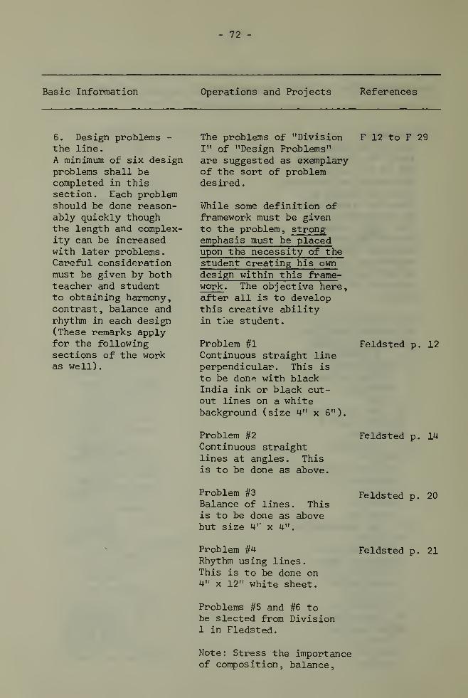
- 72 -
Basic Information Operations and Projects References
6. Design problems -
the line.
A minimum of six designproblems shall becompleted in thissection. Each problemshould be done reason-ably quickly thoughthe length and complex-ity can be increasedwith later problems.Careful considerationmust be given by bothteacher and studentto obtaining harmony,contrast , balance andrhythm in each design(These remarks applyfor the followingsections of the workas well).
The problems of "DivisionI" of "Design Problems"are suggested as exemplaryof the sort of problemdesired.
While some definition offramework must be givento the problem, strongemphasis must be placedupon the necessity of thestudent creating his owndesign within this frame-work . The objective here,after all is to developthis creative abilityin the student.
Problem #1Continuous straight lineperpendicular. This is
to be don^ with blackIndia ink or black cut-out lines on a whitebackground (size 4" x 6").
Problem #2Continuous straightlines at angles . Thisis to be done as above.
F 12 to F 29
Feldsted p. 12
Feldsted p. 14
Problem #3
Balance of lines. Thisis to be done as abovebut size 4 r x 4".
Feldsted p. 20
Problem #4Rhythm using lines.This is to be done on4" x 12" white sheet.
Feldsted p. 21
Problems #5 and #6 tobe sleeted from Division1 in Fledsted.
Note : Stress the importanceof composition, balance,

- 73 -
Basic Information Operations and Projects References
7. Design problems- area and value.
A minimum of six design
problems which are
ordered in difficultyand which emphasizeconsideration of design
elements shall be
completed in this
section.
8. Design problems- texture.
A minimum of four
design problems
neatness of presentation,''filling" the pictureplane in this assignment.
All these problems are
to be presented on a
colored cardboard with
a title block indicatingthe title of the
assignment, course,
and student ' s name
.
Problem #2
Value contrastsProceed with this
problems as indicated
in the text.
Problem #3
Area and Values.
Size of design: 5;: x 8 !:
Straight line design.
Problem #2
Area and Values.
Angles plus curves.
Problems #5 and #6 to be
selected from Division II
in Feldsted.
Note: The problems are to
be presented on a cardboard
of any size the student
wishes. Title block should
be neatly arranged with
other elements. Again,
stress the importance of
the elements of design
and relate them to each
specific problem. Arrange
for "critiques' .
The problems of "Division
IV of 'design Fundamentals
Feldsted p. 32
Feldsted p. 32
Feldsted p. 36

- 74 -
Basic Information Operations and Projects References
which are orderedin difficulty andwhich emphasizeconsideration ofdesign elementsshall be completedin this section.
9. Design problems- color
.
are suggested as exemplary.
Problem #1
Texture simulation.Use 3 ,! squares insteadof 4 1, squares
.
Problem #1Texture design.Size 60 sq.. in. minimum.
Two additional problemsmay be selected.
Note : Use at leastthree textures (i.e.
burlap, cardboard, etc.)Colors : one color pluscolors of natural textures.
Problem #3
Value harmony. Mountcolor squares on blackbackground
.
Problem #4Neutrality harmony.
Problem #5Hue harmony.
Plus two additionalproblems of colordesign and balance
:
1. Size 4' ; x 8 ;
Colors: monochromaticcolor scheme.Lines : angles andcurves
.
2. Size 4' x 8'
Colors : complementarycolor scheme.Lines: angles, straightsand curves
.
Note: all these are to bebalanced and mounted on a
Feldsted p. 60
Feldsted p. 63
Feldsted p. 49
Feldsted p. 49
Feldsted p. 49

- 75 -
Basic Information Operations and Projects References
background sheet togetherwith a title block. The
student should be remindedagain of the importance ofpresentation in all designproblems
10. Design problems The student is required- space. to build a model (size
optional) of a special
problem using lines in
three-dimensions (curves,
angles, straights, etc.)
Materials : balsa wood
,
wire, string, paint, wood
base.
Objective: To create order
(visually) using lines
and/or planes in three
dimensions.
Notes
:
1. The order of complexity
of the problems of Sections
6, 7, and 8 should increase
throughout the series, Care
should be exercised that the
problems do not become very
complex and therefore tedious
and difficult to criticise
in clear-cut fashion.
2. Students and teachers are
reminded that it is extremely
important that all products
of this unit be preserved and
carried forward to the next
year of the course.
3. It is suggested that the
unit of work be suitably brought
to a conclusion with a well dis-
played exhibition of work. (This
device should also be employed on
a class basis, on the completion
of each problem for criticism
and discussion purposes.)

- 76 -
Basic Information Operations and Projects References
Unit VII: Blueprint Reading (Graph
i
c Interpretation) - 20 hours
Recommended Workbook: ''Blueprint Reading for the Construction Trades"- Bellis and Schmidt.
Introduction andDefinitionBlueprint reading, or(more recently) graphicinterpretation, refersto the understandingof ideas and instruc-tions which are ex-pressed on drawings
.
In all manufacturingand service trades,drawings and sketchesare used to present aclear, concise, andcomplete set of in-structions . It is
through these thatthe engineer or design-er communicates withthe skilled tradesman.
The proper use andinterpretation ofstandardized methodsis an integral partof this graphic lan-guage. This languageinvolves an under-standing of lines,sections , symbols
,
dimensions, conventions,notations and titles.
ObjectivesTo teach the student tointerpret practicaldrawings into workingideas
.
Present several simple tomore complex dimensionedorthographic drawings forinterpretation
.
Present several dimen-sioned pictorial drawings(isometric or oblique)for interpretation.
Present several unfamil-iar dimensioned ortho-graphic drawings andhave the student transferdimensions
.
Present several unfamil-iar dimensioned isomet-ric or oblique drawingsand have the studenttransfer dimensions toan orthographic
Present various detaileddrawings to check orallythe students ' ability toidentify lines, surfacesand sections.
Present working drawingsfrom any or all of thefollowing: Mechancial,sheet metal, structuralsteel, reinforced con-crete, architectural,piping, electrical,welding, etc.
T. A. Diamondor any otherintroductorytext.
T. A. Diamondor any otherintroductorytext.
Select at
random fromavailabletexts.
Blueprint Read-ing Tests fromthe varioustrades or ob-tain actualprints forindustry touse as
reference.

- 77 -
Basic Information Operations and Projects References
To develop the studentsskill in reading workingdrawings with speed andaccuracy
.
To stimulate interestin and increase thestudents' technicalknowledge of specifictrades
.
ADDITIONAL REFERENCE BOOKSBlueprint Reading (General 6 Specific)
1. American Tech. Blueprint Reading for the Building Trades. Pt. I
2. American Tech. Blueprint Reading for the Building Trades. Pt. II
3. Bellis, H. F. and W. A. Schmidt. Blueprint Reading for the
Construction Trades . Toronto: McGraw-Hill Co. of Canada Ltd.
4. Bennett. Blueprint Reading for the Welders . New York: DelmarPublishers Inc. (Thomas Nelson 8 Sons (Canada) Ltd.)
5. Coover, Shriver L. Industrial Arts £ Blueprint Reading . Toronto:
McGraw-Hill Co. of Canada Ltd., 1961.
6. Coover, Shriver L. and J. D. Helsel. Programmed Blueprint
Reading. Toronto: McGraw-Hill Co. of Canada Ltd., (5 books),1966":
7. D' Archange lo. Blueprint Reading for the Plumbing Trades . New
York: Delmar Publishers Inc. (Thomas Nelson £ Sons (Canada)
Ltd.)
8. Delmar Publishers. Advanced Bluprint Reading Vol. I .
9. Delmar Publishers. Advanced Bluprint Reading Vol. II .
10. Delmar Publishers. Blueprint Reading & Sketching for Electrical
Trades, Commercial .
11. Delmar Publishers. Blueprint Reading £ Sketching for Electrical
Trades, Residential .
12. DeVette. Blueprint Reading for the Metal Trades . Wisconsin:
Bruce Publishers.

- 78 -
13. Diamond, Thomas 6 R. D. Ryan. A Primer of Blueprint Reading .
Wisconsin: Bruce Publishers.
14. Heine, G. M. How to Read Electrical Blueprints . Toronto:McGraw-Hill Co. of Canada Ltd., 1954.
15. Jensen, Louis E. Automotive Drawing Interpretat ion . New York:
Delmar Publishers Inc., 1962. (Thomas Nelson & Sons (Canada) Ltd.)
16. Kenney, Joseph E. Blueprint Reading for the Building Trades .
Toronto: McGraw-Hill Co. of Canada Ltd., 2nd edition, 1955.
17. Nicholson, Fred and C. Baughman. Blueprint Reading . Toronto:D. Van Nostrand Company, 2nd edition, 19 59.
18. Olivo, C. T. and A. V. Payne. Basic Blueprint Reading and Sketch-ing . New York: Delmar Publishers Inc., 1952. (Thomas Nelson£ Sons (Canada) Ltd.)
19. U. S. Government Printing Office. Blueprint Reading £ Sketching .
U.S. Navy Courses .

- 78 -
PART TWO - BUILDING CONSTRUCTION
(Materials and Methods - 65 hours)
The following units related to Building Construction are tobe taught in the drafting room by the drafting instructor, and whereapplicable, related directly to architectural drawings. It is impera-tive thac the drafting and the building construction instructors workin close harmony with each other in order that their students mayobtain the greatest value from this theory and the practical aspectsof Part Two - Building Construction.
NOTE: This study should be limited to the more common materials ofconstruction and should be concerned with information whichwill be most useful to a draftsman. Specific information regard-ing such things as nominal and actual sizes, grading, physicalproperties and structural attributes, etc., should be learned.
Basic Information Operations and Projects References
Unit I: Materials
A. Wood - Common woods
and their characteris-tics, seasoning,defects and blemishes,sizes, grades, commonforms - strips, boards,dimension, heavyjoists, siding, floor-
ing shiplap and
dressed and matched,board measure.
B. Plywoods - Firs and
poplar, properties,advantages and dis-
advantages ,grades
,
sizes, common uses -
construction, cabinet-
work, siding, sheath-
ing , underlay
.
C. Fasteners - Nails
and nail sizes; screws- sizes: material
Study of wood samplesand charts
Films
Theory
Examine nails, screws,
nail charts, screw
charts
A. SchwanklIdentificationof wood -
CanadianLumberman'sAssn. Mix
and Cirou,B
.
C . LumberManufacturers
'
Assn. StandardGrading andDressing Rules.
Miller ChptrXill. XV, XVI
Hammond et al

- 80 -
Basic Information Operations and Projects References
types; glues - typesand uses.
D. Finishing Materials- abrasives, flint,garnet , aluminum oxide
,
steel wool,pumice
stone, rotten stone,polishing compound,paint s , lacquers
,
varnishes , sealers
,
stains, fillers,thinners and solvents;purposes of finishingand common methods.
E. Hardware - hinges,locks, stops, bolts,catches, pulls,garage door hardware
,
sash hardware , tracks
.
F. Concrete - defini-tion, characteristics,mass concrete, rein-forced concrete, matrix,aggregates, gradingand sizing of aggre-gates, admixtures,proportioning, mixingprocedure
, pouring
,
vibrating, joints,finishing procedures
,
curing, strengths,forms , concreteblocks
, precastconcrete, cast in
place concrete, post-tens ioned concrete,pre-stressed concrete.
Examine materials andfinished wood samples.
Theory
Study samples andcatalogues.
Films
.
Field trips and reports.
Norton andBehr ManningInst. ManualsHoltrop andHj orth
Stanley cata-logue #81.
Miller ChptrXXIV
Canada CementCo. Ltd. -
informationbooklets andtechnical data
Steinberg andStempel.Ron C. Smith
Unit II: The Foundation
A. Footings - purposes,sizes, materials,
Complete sectiondrawings.
Wilson

- 81 -
Basic Informat i ori Operations and Projects References
depth, connectionwith foundation,post footings, bearingwall footings, soils
for footings.
B. Foundation Walls -
size , materials
,
framing of openings
,
form construction,mud sills.
Study workingdrawings.
Films
Field trip
Ron C. Smith,
C.M.H.C.HousingStandards
C. Basement Floor -
size, material, base
material, framing ofopenings , forms and
placing.
Unit III: Floor Framing
A. Bearing Elements -
posts, bearing parti-
tions, beams - types,
and construction,materials and joining
methods
.
Calculations and
tables
.
B. Sill Construction- box sill, cast -in
joists. Joists - size,
maximum span, spacing,
material, hangers,
br idging , subfloor
.
Framing floor openings.
Section and elevation
drawings
.
Theory.
Section drawings.
Study models.
Field trips.
Ron C. Smith
"Framing
,
Sheathing and
Insulation i; -
Delmar Pub-
lication.C.M.H.C.Standards
Unit IV: Wall Framing
A. Framing Systems -
western or "platform''
framing, post and beam
framing
.
Ron C. Smith

- 82 -
Basic Information Operations and Projects References
B. Wall construction -
studs, plates , headers
,
cripples, sills, cornerposts, partition posts,window and door open-ings, sheathing,bracing.
Examine materials
,
specifications
,
standards.Orthographic andsection drawings.
"Framing Sheath-ing and Insula-tion" - DelmarPublication.Wilson
C. Interior Partitions1. Load bearing.2. Non-load bearing.3. Plumbing walls.4. Tying walls toceiling.
Unit V: Ceiling Framing
Joists - sizes, spacing,framing of openings
,
ceiling, backing, joisthangers
.
Calculations and tables
Study working drawings, Ron C. Smith
Unit VI : Room Framing
A. Roof Shapes - shed,gable , hip
, gambrel andintersecting roofs,flat roofs
.
Theory only, Ron C. Smith
B. Roof Framing Terms1. Rafters - common,hip, jack, valley,cripple jacks, valleyj acks
.
2. Rafter terms -
span, run, unit run,unit span, unit rise,pitch, birdsmouth,seat cut, plumb cut,check cut , overhang
,
backing, dropping,true length andshortening.
Theory and Field trips Ron C. SmithWilson
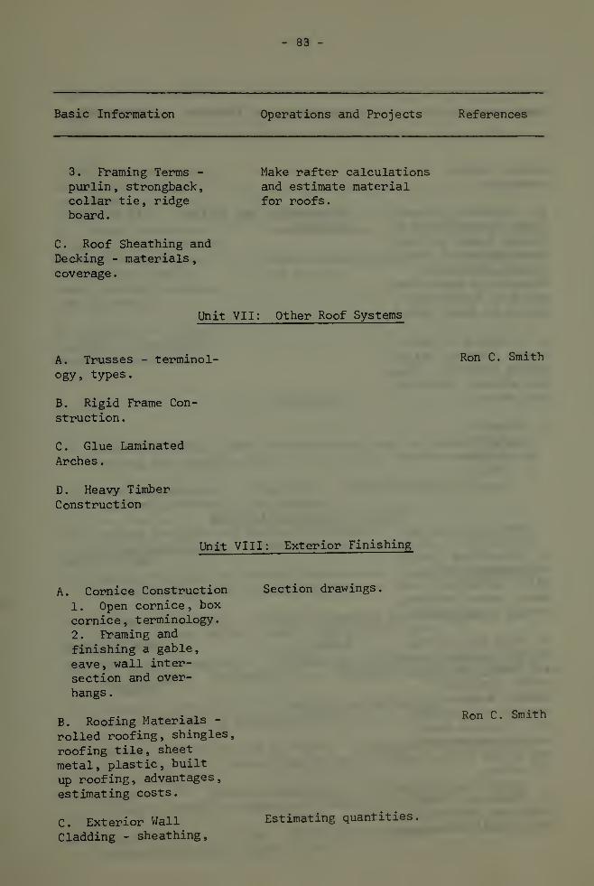
- 83 -
Basic Information Operations and Projects References
3 . Framing Terms -
purlin , strongback
,
collar tie, ridgeboard.
Make rafter calculationsand estimate materialfor roofs.
C. Roof Sheathing andDecking - materials
,
coverage
.
Unit VII: Other Roof Systems
A. Trusses - terminol-ogy, types.
B. Rigid Frame Con-
struction.
C. Glue Laminated
Arches
.
D. Heavy TimberConstruction
Ron C. Smith
Unit VIII: Exterior Finishing
A. Cornice Construction
1. Open cornice, box
cornice , t erminology
.
2. Framing and
finishing a gable,
eave, wall inter-
section and over-
hangs .
B. Roofing Materials -
rolled roofing, shingles,
roofing tile, sheet
metal, plastic, built
up roofing, advantages,
estimating costs.
C. Exterior Wall
Cladding - sheathing,
Section drawings.
Ron C. Smith
Estimating quantities,

- 84 -
Basic Information Operations and Projects References
papers, sidingmaterials.
D. Finishing of Open-ings - installation ofwindow frames and sashinstallation of doorframes, (standarddetails for wooden sashand door frames onlyshould be dealt with.)
E. Flashing of Open-ings - Chimney, valley,siding divisions , doorsand windows ; materialsand methods
.
F
.
Masonry1. Materials2
.
Mortars3
.
Bonds
Orthographic and sectiondrawings.
Mix and Cirou
Unit IX: Interior Finishing
A. Insulation - bats,rigid board, loosefill - materials , pur-pose, vapour barriers,method of installing.
B. Wall and Ceilingfinish - plaster, plas-
ter board, ten-test,common syntheticboards , wood trims
,
veneers and plywoods
,
tile, plastic lami-nates - where usedand method of ap-plication.
C. Flooring - T. & G.
softwoods and hard-woods , roll coverings
,
Ron C. Smith
Theory Mix and Cirou
Wilson

- 85 -
Basic Information Operations and Projects References
tile-properties, whereused, method of ap-plication.
D. Stair Construction- open notched stringershoused stringers , con-crete stairs , riser-tread design, headroomand clearance.
Check standards.
Study working drawing
and sections
Ron C. SmithC.M.H.C.HousingStandards
E. Cabinets - kitchencabinets , constructiondetails, estimating.
REFERENCES
1. British Columbia Lumber Manufacturers' Association. Standard
Grading and Dressing Rules . B. C. Lumber Manufacturers' Assoc.
2. Canadian Lumbermen's Association. Identification of Woods.
Canadian Lumbermen's Association.
3. Central Mortgage and Housing Corporation. Canadian Wood Frame
House Construction. Central Mortgage and Housing Corporation.
4. Central Mortgage and Housing Corporation. Hous ing Standards .
Central Mortgage and Housing Corporation.
5. Delmar Publications. Framing, Sheathing and Insulation. Don
Mills: Thomas Nelson 6 Sons (Canada) Ltd., 1946.
6. Delta Manufacturing Co. Gettingjthe Most Out ot Your Circular
Saw £ Joint er,. Pittsburg, P. A. : Rockwell Manufacturing Co., 1953,
7. Hammond, James J. et al. W^o_dwprking_J^chno]^gy. Don Mills:
General Publishing Company, 1961.
8. Holtrop, William F. and H. Hjorth. Principles of Woodworking.
Milwaukee, Wise: Bruce Publishing Co., 1961.
9. Miller, H. G. Building Construction ;.._ Mat erjals_jffid Methods..
Toronto: Macmillan Company of Canada Ltd., 1968.
10. Mis, Floyd 6 E. H. Cirou. Practical Carpentry. Don Mills:
General Publishing Company, 1963.

- 86 -
11. Schwankl, Alfred. What Wood is That? Don Mills: LongmansCanada Ltd. , 19 57.
12. Smith, Rcnald C. Principles and Practices of Light Construction ,
Scarborough: Prentice-Hall of Canada Ltd., 1963.
13. Steinberg, Joseph and Martin Stempel. Practices and Methods ofConstruction Scarborough: Prentice-Hall of Canada Ltd., 19 57.
14. Wass , Alonzo. Manual of Sturctural Details for BuildingConstruction . Scarborough: Prentice-Hall of Canada Ltd., 1968.
15. Wilson, J. D. Practical House Carpentry . Scarborough: McGraw-Hill Company, 1957.

- 87 -
PART TWO - BUILDING CONSTRUCTION
(Practical - 130 hours)
Purpose
This unit is intended to develop a practical knowledge ofbuilding construction principles, methods and materials essential tothe draftsmen who will be planning and producing working drawings forsuch structures.
Methods of Approach
It is expected that the student will attain this knowledgethrough the experience of making these constructions or models of themin a practical shop situation. Emphasis should be placed on the cor-rect procedures for combining building materials to form a structurewith accent being placed upon a knowledge of existing common systemsand building materials.
It iii intended that the student should achieve a practicalunderstanding of the function, capabilities, and limitations of thebasic hand and machine tools of construction. The development of ahigh degree of skill in their use is not an objective but an appre-ciation of craftsmanship should be developed.
It is imperative that the building construction and thedrafting instructors work in close harmony with each other, in orderthat their students may obtain the greatest value from the theory as
taught by the drafting instructor, and the practical aspects of the
following units. The instructor in the shop should be aware that the
drafting instructor is covering most of the theory and should there-
fore place the emphasis on practical experiences. Each portion should
reinforce and give meaning to the other.
Basic Information Operations and Projects References
Unit I : Shop Orientation
A. Orientation - Shop Tour the shop facilities
procedure, regulations, explaining the use of
forms, tools and tools and equipment in
machines, attitudes, general,
discipline.

- 88 -
Basic Information Operations and Projects References
B. Shop Safety (to bestressed continuallythroughout the course)
Draw attention to haz-ardous equipment and theneed for strict observ-ance of regulations.
Unit II: Hand Tools and Bench Work
A. Care, adjustmentand proper use of thefollowing tools
:
1. Measuring tools -
rules and tapes
.
2. Layout and mark-ing tools - framingsquare , try square
,
combination square,sliding T-leveldividers, scriber,marking gauge,mortise guage, buttguage , marking knife
,
trammel points,straight edge.
3. Cutting tools -
ripsaw, crosscut saw,compass saw, back saw,coping saw, chisels,hatchets, axes,planes-jointer , fore,jack, smooth, blockbullnose cabinet andspecial planes
.
4. Boring Tools -
bits and drills
,
countersinks, depthgauge , bit brace
,
hand drill, pushdrill, twist drills.5. Assembling Tools -
hammers , screwdrivers
,
nail sets, wrenches.6. Leveling andplumbing tools -
spirit level, linelevel, level sights,
Demonstrate tools asrequired for use.
Cut out rough stock;square up stock; layoutand make the followingwood joints: dado,cross lap, corner lap,open mortise and tenon
,
mitre.
Exercises and projectsshould be selected in
keeping with the toolsto be learned as wellas the joints andoperations
Introduce and demonstrateas required in theprogram
.
Miller
Holtrop S
Hjorth
Wilson
Ron C. Smith
Ron C. Smith

- 89 -
Basic Information Operations and Projects References
plumb bob , builder '
s
level.7. Holding tools -
C-clamps, bar andpipe clamps, adjust-able hand screws,and woodworkersscrews , woodworkersvices.
B. Finishing Materials- abrasives - flint
,
garnet , aluminum oxide
,
steel wool, pumicestone, rotten stone,
polishing compounds
,
paint lacquers,varnishes , sealers
,
stains , fillers
.
C. Hardware - common
types.
Demonstration andoutlining the purposeis all that is neces-sary here.
Apply hardware such as
locks and hinges.
Holtrop andHjorth
Unit III: Machine Woodworking Tools
A. Correct methods of
use, adjustment, safety
and capabilities of the
following woodworking
machines
:
1. Circular Saw
(table and radial
arm)
Jointer
3. Thickness planer -
emphasizing the
orderly routine to be
followed in machine
dressing of lumber.
Ripping, crosscutting,
level cutting, dadoing
and grooving operations
on suitable projects
and models.
Face and edge jointing,
dressing procedure in
conjunction with other
machines, level joint-
ing, chamfering and
rabbeting.Dressing lumber to size
in conjunction with
the circular saw and
jointer.
Delta books
Miller
Holtrop S
Hjorth

t 90-
Basic Information Operations and Projects References
Unit IV: Joinery
A. Types of joints,methods of constructionand uses
.
B. Cabinet Construction
Construction of the
following joints: dado,rabbet
stongue and
groove, half lap, miter.
Cabinet constructionsuch as shelves , drawers
,
doors and surfacing ofbasic contemporarysystems
.
Stanley ToolGuide
.
Holtrop 6
Hjorth
Hammond et al
Ron C. Smith
Holtrop 6
Hjorth.
Unit V; Building Construction
A. Site and Foundation1. Location, con-tour, types of soil,services
.
2. Locating proper-ty corner stakes
,
locating the buildingcorners , batterboards
.
3. Foundation types,footing forms andfoundation forms
,
bracing ties, open-ings.
B. Floor FramingMethods
1. Western or "plat-form 17 framing.2. Post and beam.
C. Systems of FrameConstruction (Contem-porary methods offraming only)
Field trips to studylot layout , buildinglines, levels, footings,foundation walls, postfootings and posts;concrete forms, mixing,placing, finishing andcuring of concrete.
Some students may com-plete minimalic con-struction of floorframing, full scaleframing of typicalsections or fullscale construction ofsmall buildings.
Have students performplate layouts on 2 x 4's
indicating corner andpartition posts, al-lowances for doors and
Ron C. Smith
Mix and Cirou
Wilson
Ron C. Smith

- 91 -
Basic Information Operations and Projects References
D„ Roof FramingHethods
1. Roof shapes -
shed,, gable, hip,gambrel., inter-secting and flat roofs
window openings. Framewall sections, make a
story rod.
Students layout raftersproblems on 2 x 4 , in-
volving common hip andvalley rafters. Calcu-late material requiredfor roofs.
Uass ardSaunders
Students may constructscaled down door andwindow frames usingfull size stock.
Pen C. Smith
Field trips to studyframing methods andmaterials.
E. Stair Construction1. Parts of a stairstringer . tread .
riser, cant strips,handrail, newelpost . balustrade
.
F. Exterior finishing1, Cornice construc-
tion.
2. f.oofing materialsand methods
.
3. Exterior wall-
cladding, and open-
ings .
Layout only, on fullsize stock, stair
stringers for bothopen and housed stairs
.
"here snail buildings
are being constructed-,
students may completethe cornice construc-
tion field trips to
exai! ine other types
.
Ron C. Smith
Wilson
Mix and Cirou
Pon C. Smith
RFFERFIICES
Koltrop and I north. Principles of Woodworking .
Publishing Company, 1961.
lscons.in ruce

- 92 -
Miller, H. G. Hand and Machine Woodwork . Toronto: Macmillan ofCanada, 1962.
Mix, Floyd and E. H. Cirou. Practical Carpentry . Don Mills: GeneralPublishing Co., 1963.
Smith, Ronald C. Principles and Practices of Light Construction.Scarborough: Prentice-Hall of Canada Ltd., 1963.
Stanley Tool Guide. Stanley Tools . New Brittain, Connecticut.
Wass, Alonzo and G. A. Saunders. Building Construction - Roof Framing ,
Scarborough: Prentice-Hall of Canada Ltd., 1960.
Wass Alonzo. Manual of Structural Details for Building Construction.Scarborough: Prentice-Hall of Canada Ltd., 1968.
Wilson , J . Douglas . Practical House Carpentry . Scarborough : McGraw-Hill Company of Canada Ltd., 19 57.


<ptm5j.
>m*m i
»WB-''*V-
rSlH
-» fliufc!
-