Embed Size (px)
Citation preview

Current Solutions for Future Networks
Chris Waller
CRYOGENIC CLUSTER DAY PROGRAMME SEP 28 2011
Superconducting Fault Current Limiters
The John Vandore Challenge
• Squeeze my normal 110 slides which takes an hour into 15 minutes!
• So here goes.
Current Solutions for Future Networks

The fault current challenge - 1
Current Solutions for Future Networks
G Generator
Circuit breaker
Load
Copper line
G
Short circuit:Fault Current unrestricted by load
GCircuit breaker interrupts fault current

The fault current challenge - 2
Current Solutions for Future Networks
Image © Palm Harbor Fire Department
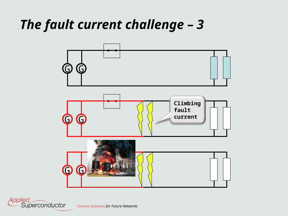
The fault current challenge – 3
Current Solutions for Future Networks
G
G G
G
G G
Climbing fault current

The fault current challenge - 4
Current Solutions for Future Networks
GG
Split the network
Upgrade Circuit Breakers
Install Reactors
Install high resistance Transformers

The fault current challenge - 5
Current Solutions for Future Networks
G GCircuit breaker can operate safely
G GInstant rise in resistance limits fault current
GGZero resistance

The fault current challenge - 6
Current Solutions for Future Networks
132kV
fault prone network
SensitiveLoad
Too Much Load
Plenty of capacity
132kV
33kV
11kV 11kV 11kV
33kV40MW
Wind farm
11kV 11kV
Loadsharing
Securityof supply
Generator
Generator
Generator

Key characteristics of Fault Current Limiters based on superconducting materials
Under normal operation a fault current limiter inserts negligible impedance into the network
When a fault occurs the limiter‘s impedance rises rapidly, reducing the current flowing through it
The fault current challenge – eureka
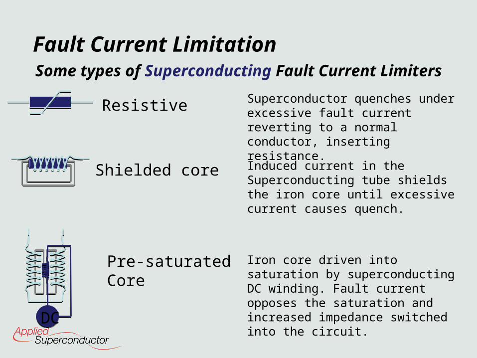
Some types of Superconducting Fault Current Limiters
Resistive
Shielded core
Pre-saturatedCore
Induced current in the Superconducting tube shields the iron core until excessive current causes quench.
Superconductor quenches under excessive fault current reverting to a normal conductor, inserting resistance.
Iron core driven into saturation by superconducting DC winding. Fault current opposes the saturation and increased impedance switched into the circuit. DC
Fault Current Limitation
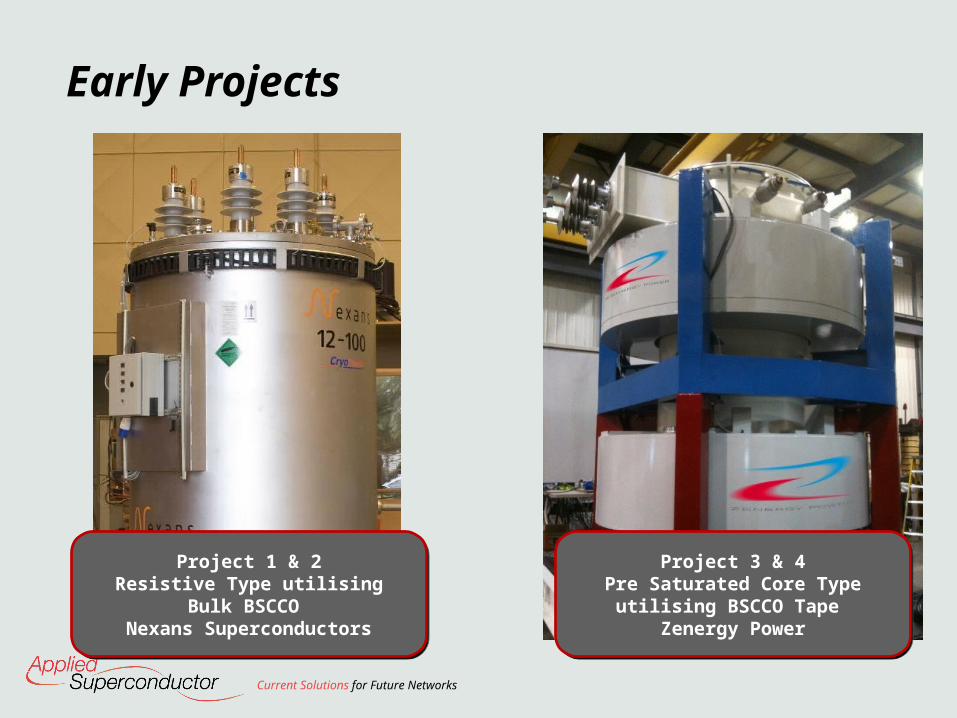
Early Projects
Current Solutions for Future Networks
Project 1 & 2Resistive Type utilising Bulk
BSCCO Nexans Superconductors
Project 1 & 2Resistive Type utilising Bulk
BSCCO Nexans Superconductors
Project 3 & 4Pre Saturated Core Type
utilising BSCCO Tape Zenergy Power
Project 3 & 4Pre Saturated Core Type
utilising BSCCO Tape Zenergy Power

Early Projects
Current Solutions for Future Networks
11kV / 100A
11kV / 100A
20102010 20112011 2012201220092009
11kV/400A11kV/400A
11kV/1250A11kV/1250A
33kV / 800A 33kV / 800A
11kV/ 1250A MgB2 demonstrator
11kV/ 1250A MgB2 demonstrator
operation
operation
20132013
1st in commercial network

B (magnetic field)
J (current density)
T (Temperature)
Superconductingproperties
Normalconductingproperties
Normalconductingproperties
Normalconductingproperties
Superconductors remain in the superconducting state as long as the current, temperature and flux density remain below the critical values.
Critical CharacteristicsResistive Limiters

Res
ista
nce
Superconducting range
Normal range
Cri
tica
l V
alu
e
Low
High
Equivalent circuit
Superconducting Characteristics – Resistive Fault Current Limiters
Resistive Limiters

fault current
limited fault current
Up to 90% clampingClamps within 1.5 msRemoves DC component
Resistive FCL – Limiting Behaviour

ETI Commissioned Project secured in June 2011 to develop a MgB2 type SFCL with a view to targeting the future mass market.
The prototype will be installed in substation on Western Power Distribution’s network in Summer 2013.
Key parameters
•Nominal operational voltage and frequency: 11kV, 50Hz
•Maximum normal load current: 1250A
•Prospective fault current – 50kApk (20kArms) reduced to less than 7kApk
Resistive MgB2 SFCL Development

HV Bushings
Helium Compressors
Heat Exchanger
Current Limiting Modules
Resistive FCL – Key Components
• Using the quench: Even quenching, no hot spots, material homogeneity
• Wire heating: Removal of the heat (0.96MJ in 120ms)reset within 3 minute
• Low thermal losses Current leads
AC losses in superconductor/sheath
Induced losses in cooling systems
Enclosed volume & thermal radiation
Resistive MgB2 SFCL - Challenges

• Customer driven issues Fail safe
No maintenance.
Low carbon footprint
Competitive with alternative options
Low noise.
• Suppliers: Limited MgB2 wire suppliers. All interested in MRI as mass market.
Cryogenic components suppliers needed.
This is why we are here!
Resistive MgB2 SFCL - Challenges

Current Solutions for Future Networks
Thank you !Superconducting Fault Current Limiters are a bottleneck component in the rise of Clean Technologies and Smart Grids and critical to meet Low Carbon targets