Embed Size (px)
Citation preview

TRANSACTIONS ON EMERGING TELECOMMUNICATIONS TECHNOLOGIESTrans. Emerging Tel. Tech. 2015; 00:1–12
DOI: 10.1002/ett
RESEARCH ARTICLE
Cubic Spline Extrapolation for Uplink Channel QualityPrediction in LTE-A with Carrier AggregationMaria A. Lema, Mario Garcia-Lozano, Silvia Ruiz
ABSTRACT
In the context of wireless communications, an accurate channel state information (CSI) is key for a correct radioresource management. In the uplink of Long Term Evolution Advanced (LTE-A), obtaining up-to-date CSI relies on userequipments (UEs), that send sounding signals throughout the available bandwidth. This procedure is quite challengingwhen considering the ever increasing bandwidth demands and the introduction of carrier aggregation. Information frommany radio resource blocks becomes outdated and unreliable for scheduling operations. Besides, interference values aremuch more variant than the downlink due to changes in the position of interferers and their transmission power. This workproposes the introduction of cubic spline extrapolation to obtain a prediction horizon that allows extending the reliabilityof the channel quality evaluation along time. Though very high interference levels and variations thereof imply no gains,the mechanism succeeds with moderate interference, situation that can be provided by interference cancellation strategies.Copyright © 2015 John Wiley & Sons, Ltd.
1. INTRODUCTION
Mobile traffic has been growing enormously due tothe demands for multimedia, social networks and theincreasing use of cloud based services. Despite theadvances made in the fourth generation (4G) designs,challenging requirements are set to be targeted in theforthcoming fifth generation (5G). Among others, highersystem capacity, massive device connectivity and higherdata rates are some of the issues to be accomplishedby the new 5G technology. To achieve this, the use ofcarrier aggregation (CA) is mandatory, since provideswider transmission bandwidths, and allows the system toimprove the area spectral efficiency and system capacity.
One of the aspects that allows to further increasespectral efficiency is the existence of reliable up-to-datechannel state information (CSI), which is also an essentialsupport for many of the transmission procedures. In theuplink (UL) of Long Term Evolution advanced (LTE-A) systems, the UL channel response is obtained by theeNodeB (eNB) after receiving and processing the soundingreference signals (SRS) sent by the user equipment (UE),which allows to determine the channel quality information(CQI) [1, 2]. Accurate channel state information (CSI) iskey to capitalize improvements brought by promising radioresource management (RRM) algorithms: this informationcan be used at the discretion of the scheduler to supportfrequency selective scheduling. Sounding signals may bealso used to perform effective beamforming in in both UL
and downlink (DL), where a correct CSI estimation playsan important role and it is one of the paramount technicalissues to be solved in the context of 5G massive multiple-input-multiple-output (MIMO) systems.
In a system operating with several aggregated compo-nent carriers (CCs), the bandwidth to be sounded increases,which complicates the CSI acquisition task. In powerlimited UEs the power spectral density decreases as thetransmission bandwidth increases, which might lead tounsatisfactory CQI measures. CA transmissions in the ULmay imply further power limitations to the UE, sincemaximum power reduction (MPR) is carried out in ULnon-contiguous transmissions, to contain the PAPR andhence, the out of band emissions. To avoid inaccurate CQImeasurements due to decreased signal power density, LTEallows the eNB to manage sounding radio resources byallocating narrowband SRS transmissions; this allows toeffectively obtain reliable sounding measures. In a CAcontext, this solution can be counterproductive since itrises the time delay between measurements, and channelinformation becomes outdated and less trustworthy. TheeNB should discard frequency parts with outdated SRSs,which yields to a reduction in frequency diversity gains.
A second problem the UL sounding must deal with, isthe intrinsic rapid variations of the SINR. This is not onlydue to short term fading, but also because of schedulingdecisions. With every transmission time interval (TTI),allocated resources are updated and the interferenceperceived on each physical resource block (PRB) changes.
Copyright © 2015 John Wiley & Sons, Ltd. 1Prepared using ettauth.cls [Version: 2012/06/19 v2.10]

A demonstration of the Trans. Emerging Tel. Tech. class file A. N. Other
This implies fast signal to interference noise ratio (SINR)variation and reduces the sounding reliability, eventuallygenerating errors in the link adaptation and reducing theUE throughput.
Given the UL problem and the need for improvingCSI to support LTE-A features in CA contexts, wepropose a cubic spline extrapolation method to predictthe UE SINR within a reasonable prediction horizon.This provides a means for the scheduler to extend thevalidity of SRS information. The proposal is testedunder different interference scenarios, and interferencecancellation (IC) has also been considered to support theprediction procedure under harsh interference conditions,and therefore help to further improve the channelestimation. Note that the term channel estimation may alsorefer to the the estimation of the channel impulse responseusing the combined knowledge of the transmitted andreceived signal; assuming the channel affects like a filter,these techniques aim at recovering the received signal byestimating the filter coefficients. In this paper channelestimation refers only to the SINR or CQI estimation atthe eNB side, with the aim of improving transmissionprocedures.
This paper is organized as follows: Next sectionprovides a short survey of the prior work done in thistopic, main conclusions of it are described and the researchopportunities are detailed. Section 3 provides the readerwith some background information regarding the ULsounding system, section 4 describes the main limitationsencountered when pursuing a correct CSI acquisition andsection 5 describes the proposed solution. The systemmodel is described in section 6 and the evaluationmethodology is described in section 7, followed by theresults in section 8. Finally, this paper ends with the mainconclusions of this study, in section 9.
2. LITERATURE SURVEY AT A GLANCE
The 3GPP community has recognised that an adequatemanagement of SRS configuration parameters in LTE-AUL can lead to improvements in the system performance.In [3] authors evaluate the gain of non-contiguous resourceallocation in the UL considering two SRS bandwidthsetups based on the UE SINR. Results show that adiscontinuous allocation may be beneficial as it canexploit additional frequency diversity gains. However,SINR estimation errors provided by SRS inaccuracy orunavailability can lead to degrading effects. Other 3GPPcontributions already mentioned the need for differentsounding bandwidth options to avoid CQI measurementerror. This necessity was already discussed in [4],where authors propose to adaptively control the soundingbandwidth. This solution allows reducing the numberof wideband transmissions which assures lower MCSselection error due to decreased received signal powerdensity. Results show that the adaptive control is especially
effective in hyper dense scenarios with high volumesof traffic. Also, in [5] different schemes of configuringSRS across multiple CCs are discussed. Authors proposethat sounding signals should be configured separately forthe different CCs. This turns sounding more flexible,this can be useful in heterogeneous networks interferencecoordination. Another proposal is that UEs should transmitSRS symbols only in their active CCs, meaning the onesthat are actively being used for data transmission.
The channel estimation error in the DL has beentackled by several authors. In [6], authors deal with thechannel quality indicator (CQI) delay. This CQI feedbackdelay is caused by CQI measurement at the UE side,CQI feedback and CQI processing at the eNB side. Apolynomial extrapolation method is proposed to predictthe CSI, where no second-order statistics of the SINRare required. The solution is evaluated for different UEspeeds and results show that the proposed method worksfor UEs with low variant channels. Another strategyto overcome the performance loss brought by channelestimation error is presented in [7]. Authors propose twotypes of link adaptation algorithms. The first one performsa weighted average of different past received informationof the UE, such as channel, SINR and MCS. Thealgorithm calculates the current channel, SINR or MCS byaveraging the past information in a fixed time window. Theperformance of the previous algorithm strongly dependson the time window size, therefore, authors proposethe use of a dynamically adjusted time window. Linkadaptation decisions based on the channel averaging showsto compensate better the channel estimation errors.
Other works that can be found in the literature undertakethis problem by using prediction filters. In [8] it is proposedthe use Least Mean Square (LMS) prediction method.In particular, a modified version of the normalized LMSis proposed in order to support wider CQI feedbackdelays. Improvements brought by predictions are verymuch dependent on the time difference of two consecutiveCQI measurements. When the difference is low, theLMS proposed strategy shows significant improvement,however as it increases, the LMS solution degradesthe instantaneous channel information. Results concludethat the prediction solution has the ability to improvethroughput when the time delay is less than 5 ms. Wiener-based prediction filters are also widely found in theliterature as a strategy to overcome the channel estimationerrors, [9–11]. This solution has also been proposed forthe UL [12,13]. Practical Wiener filters are obtained usingtemporal averages to approximate the cross-correlationand auto-correlation functions involved in the solution andergodicity therein is also assumed. Work in [14] comparestwo different approaches in the DL: Wiener filters withcubic spline extrapolation. The cubic spline methodconstitutes a near optimal solution in low speed UEsand it does not have the strong input/output correlationdependency the Wiener solution has. To adapt the cubicspline solution to fast moving UEs, the authors propose a
2 Trans. Emerging Tel. Tech. 2015; 00:1–12 © 2015 John Wiley & Sons, Ltd.DOI: 10.1002/ett
Prepared using ettauth.cls

A. N. Other A demonstration of the Trans. Emerging Tel. Tech. class file
simple heuristic using the autocorrelation of past samplesthat, combined with the extrapolation output, provides anaccurate prediction. Other authors consider Kalman filtersfor channel prediction in the DL [15, 16]. In the UL, workin [17] uses Kalman filtering to predict the interferencesin a time division multiple access wireless network. Thesetype of networks allow multiple, contiguous time slotsto be used by the same terminal or base station fortransmitting the data. As a consequence, the interferenceat the receiver is correlated from one time slot to the next.Based on the interference measurements in previous slotsthe interference power to be received can be predicted withthe use of Kalman filtering. To successfully implement thisfilter it is crucial to correctly estimate the process noise andmeasurement noise (both in Kalman terminology, thesenoises are used in the prediction process), which in generaldepend on the signal statistics, and in this particular studyboth noises depend on the error characteristics of theinterferences at the receiver.
Specific strategies for the UL may consider collabora-tion among different eNBs to provide a wider knowledgeof the interference map generated, which depends on theresource allocation decision of the eNB. Work in [18]proposes to exchange scheduling decisions between theeNBs, incorporating a time delay that occurs for the infor-mation exchange. Each eNB predicts the channels of itsown users using a Minimum Mean Square Error (MMSE)predictor and sends the scheduling information in twomanners, a fixed allocation decision, or the probability ofthe scheduling decision. This new scheme provides betterresults for link adaptation decisions, and in particular, theinterchange of probabilities is especially beneficial for fastmoving UEs.
2.1. Remarks from Literature Review
Table I summarizes the prediction strategies describedin the previous section in a comparative way, where themost important features are highlighted. The majority ofthe work is done in the DL, where the CSI acquisitionproblems may be similar at a first glance, but the ULindeed presents more challenges, mainly because of theinterference variability. There are several proposals thatsuggest the use of Wiener filtering, which needs secondorder statistics to compute the filter coefficients.
The Wiener filter, or any linear prediction method thatis based on the mean square error (MSE) minimization,require a previous knowledge of the SINR and channelstatistics. In general, fading channels can be studiedand the second order statistics can be derived, however,doing this while considering interferences is a much moredifficult task in the UL, where the variability follows nostatistical rule. The same rationale applies for the Kalmanfilter, where the variances of the process and measurementnoise must be estimated as an input. Among the otherprediction filters proposed, there is the LMS, which canrule out any low or high order statistics, but however,requires a constant time difference between the past CQI
Table I. Summary of prediction strategies to improve CSI
Ref # Link Strategy Statistics Interference Delays
[6] DL Polynomial 8 X X[7] DL Average 8 X X[8] DL LMS 8 8 X[9] DL Wiener S.O 8 8
[10] DL Wiener S.O 8 8
[11] DL Wiener S.O 8 8
[12] UL Wiener S.O 8 X[13] UL Wiener S.O 8 8
[14] DL Polynomial 8 X X[15] DL Kalman L.O X X[16] DL Kalman S.O X X[17] UL Kalman L.O X X[18] UL MMSE S.O X X
S.O: Second Order L.O: Low Order
0 50 100 150 200 250
−15
−10
−5
0
5
time (ms)
H (
dB)
UE channelSRS samples
Prediction horizon
SRS based channel
Figure 1. Continuous time formulation of the prediction
samples and the prediction. In the UL, the SRSs in aparticular piece of spectrum are only available after acomplete bandwidth sweep, but the scheduler may need todecide about the suitability of those resources at any time.So, a continuous time formulation for the prediction isrequired, which is mathematically tricky for Wiener basedsolutions. The main challenge of the selected predictionmethod is to provide the most accurate SINR at the time ofreception, and this decision shall be made in the schedulinginstant. In particular, the time span for predictions goesfrom one round trip time (RTT), concurring with a SRSreception, to one RTT plus the delay in SRS reception, thisinstant is the immediate one prior to the SRS reception,figure 1 shows a graphical example of this. In a CA contextthe delay in the SRS reception can be seriously affected,since larger bandwidths need to be sounded.
The proposed method, is a numeric function that ispiece-wise defined by several polynomial functions, in theparticular case of cubic splines, degree three polynomials.The spline can be used for prediction by extrapolatingthe last polynomial function, and obtaining a future valueof the curve, which is, in this case, built upon thepast SINR samples. In this sense, the use of splines
Trans. Emerging Tel. Tech. 2015; 00:1–12 © 2015 John Wiley & Sons, Ltd. 3DOI: 10.1002/ettPrepared using ettauth.cls

A demonstration of the Trans. Emerging Tel. Tech. class file A. N. Other
constitutes a much different approach compared to theprevious strategies, this mathematical method does notfilter the signal, and it can approximate functions withless computational complexity, as shown in [19]. Thecubic spline extrapolation method avoids complex errorcalculations, as in the Wiener case where the obtentionof second order statistics are mandatory; also, sinceprediction is not in a discrete form as in the previous cases,the curve provides broader information about its behaviourin the future.
2.2. Research Efforts and Main Contributions
From the previous paragraphs, a mathematical methodbased on cubic splines appears to be an interesting andpromising solution that suits well the constraints of theproblem, in particular:
1. The difficulty to estimate error measurementscorrectly in the uplink, given the rapid SINRvariability.
2. It is a continuous time formulation itself, withoutthe need for additional interpolators.
Frequency domain scheduling and link adaptationdecisions are supported by the SINR information providedby the SRS. Because of the interference variability, thetime difference between the SRS and data reception,and UE transmit power considerations, there is amisalignment between the SINR measured from the SRSand the actual one measured at the physical uplinkshared channel (PUSCH) transmission. In this sense, CSIacquisition techniques must place efforts in reducing theSINR misalignment and thereby improving the systemperformance.
Therefore, the main contribution of this work is toincrease the SRS reliability considering:
• Realistic interference generation: The generation ofUL interferences variate with time mainly due toscheduling decisions.
• SRS delays: Not only affected by the RTT, but alsobecause of hopping along the entire band. Delaysare much aggravated with the use of aggregatedcarriers.
• Low complex prediction methods.• IC techniques. Used in the eNB side to suppress
the most dominant interference sources, and hence,reduce both the average interference and itsvariability.
3. CHANNEL QUALITY INDICATORACQUISITION IN THE UPLINK
Sounding signals are sent by the UE and configuredby the eNB with the main goal of achieving up-to-dateand accurate CQI. This allows performing opportunisticfrequency domain scheduling, since the best spectrum
12
24
48
Uplink System Bandwidth
BSRS=0
BSRS=1
BSRS=2
BSRS=3
24
12 12 12
4 4 4 4 4 4 4 4 4 4 4 4
Figure 2. Sounding reference signal bandwidth configurationexample for one CSRS, expressed in PRBs
areas can be detected. Eventually it also contributes inthe decision of the best modulation and coding scheme(MCS) in the link adaptation process. SRSs are sent in thelast single-carrier orthogonal frequency division multipleaccess (SC-FDMA) symbol of the sub-frame, only one outof seven symbols are reserved for sounding purposes, andthe reference signal bandwidth is configurable. Soundingsignals can be as frequent as every second sub-frame oras infrequent as every 32th sub-frame. The eNB is incharge of selecting both cell and UE specific soundingparameters with the objective of achieving up-to-dateCQI without increasing interferences, and accounting forthe UE power headroom. All the sounding parameterssuch as maximum sounding bandwidth or frequencyposition are configured on a cell-wide basis. Specific per-UE configuration parameters are: sounding periodicity,specific sounding bandwidths, and hopping patterns.
The maximum sounding bandwidth, CSRS, is acell-specific parameter signalled via radio resourcecontrol (RRC) messages. A range of CSRS bandwidthconfigurations are available depending on the systembandwidth, these are defined in [20] in number of PRBs.For each CSRS selected by the eNB, four different UEspecific bandwidths are possible, BSRS, on the basis ofa tree structure. This allows the sounding region to beconfigured to span only in the resource blocks used, asfor example, in those ICIC schemes in which UEs arerestricted to transmit in certain parts of the spectrum.Also, narrow bandwidth soundings are desirable for powerlimited UEs, since an increase in bandwidth reduces itspower spectral density (PSD), which leads to less accurateSINR measurements [2]. Figure 2 shows a graphicalexample of the differentBSRS values that can be configuredfor one CSRS, expressed in number of PRBs. If the CSRS
selected by the eNB is 48 PRBs, then the UE may soundthe entire band in sets of 4, 12, 24 or 48 PRBs.
As said, the BSRS of UEs placed at the cell edgeshould be selected considering their low power availabilityto assure the reliability of the measurement. But, ifthe sounding bandwidth is narrow, the time to measurethe entire system bandwidth is larger, increasing theperiod between two consecutive measurements of the samepiece of spectrum (Tsound), as shown in figure 3. Thisis particularly problematic in carrier aggregated systemsmaking use of very wide bands.
4 Trans. Emerging Tel. Tech. 2015; 00:1–12 © 2015 John Wiley & Sons, Ltd.DOI: 10.1002/ett
Prepared using ettauth.cls

A. N. Other A demonstration of the Trans. Emerging Tel. Tech. class file
BSRS
frequencytim
e
Component Carrier 2Component Carrier 1CSRS,1 CSRS,2
Figure 3. Sounding procedure all UEs in the scenario follow
Both Frequency and Code Division Multiplex (FDMand CDM) are used in LTE to support a higher numberof users when sounding. FDM is done following atransmission comb structure with a factor of 2, whichmeans that only every other subcarrier is sounded, andCDM is done using a Zadoff-Chu sequence with differentcyclic shifts. For each sounding region up to eight UEscan be multiplexed via cyclic shifts, nSRS. Based on this,the combination of FDM and CDM allows to multiplex atotal of 16 UEs in the same spectrum area. In practice, thisnumber of UEs is not feasible since there are orthogonalityand interference issues, so a more realistic estimate is tomultiplex 6 to 8 UEs [2].
Following this sounding procedure, the eNB is able tomeasure the uplink channel response. Interferences fromother reference signals can be contained with the useof orthogonal code sequences; the cross-correlation ofsimultaneous eNB transmission is reduced, thus reducinginter-cell interference.
4. PROBLEM STATEMENT
The number of users sharing the spectrum as well asthe sounding bandwidth BSRS impact the delay in thechannel measurement, also the use of aggregated carriershas an impact on it. Table II shows the time delay Tsound,in milliseconds, experienced between two consecutivesounding measurements in one frequency resource block.This time delay varies depending on the number of usersconnected to the eNB and the piece of bandwidth beingsounded each TTI, BSRS. Delays shown also account forthe use of two CCs (20 MHz each), and are comparedto a single carrier (SC) scheme. Each carrier is soundedseparately on different transmission intervals, to avoidfurther power reductions inflicted by non-contiguoustransmission in the UL [21]. The delay figures show thatwith CA it increases proportionally with the number ofcarriers aggregated. The main problem of having increaseddelays in the channel measurement is the lack of upto date information in the scheduling decisions and linkadaptation. Figure 4 shows two different examples of
0 50 100 150 200 250 300
-20
-10
0
time (ms)
H (
dB)
UE channel
SRS based channel
(a) UE Channel measured by SRS with time delay of10 ms
UE channel
SRS based channel
0 50 100 150 200 250 300
-20
-10
0
time (ms)
H (
dB)
(b) UE Channel measured by SRS with time delay of30 ms
Figure 4. Channel measurement for two different Tsound
channel state measurement with the use of SRS. The firstfigure, 4(a), has a time delay between two samples of10 ms and the second one, figure 4(b), has a time delay of30 ms. A lower time delay can capture enhanced channelinformation in terms of instantaneous deep fadings.
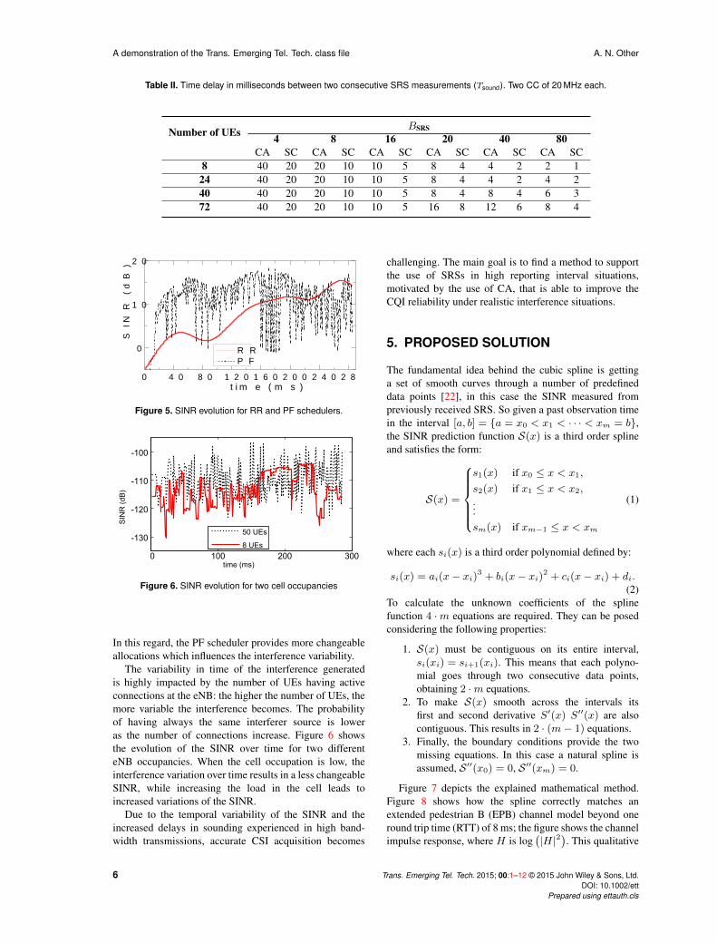
Another limiting aspect of the UL channel measurementis its intrinsic interference variability, which impacts theCQI by constantly altering the aggregate interferencelevel experienced. According to the scheduling decisions,interferer UEs may change from one transmission timeto another, and the impact on the SINR depends on thelarger or lesser the pool of candidates is: the formergenerates increased interference variability compared tothe latter. Figure 5 shows the SINR measured over thePUSCH for two different schedulers: round robin (RR)and proportional fair (PF). The simulation here is quitesimple for the RR case, UEs are always allocated in thesame order and sequentially, given that the number ofavailable resource blocks is higher than the number of UEsallocated, UEs are always allocated the same resources,resulting in a les variable interference (since interferers arealways the same). In the PF case the scheduler separatesthe process in two parts, a time domain part, where UEsare ordered based on their past acknowledged throughput,and a frequency domain part, where PRBs are allocatedwith the goal of maximizing the cell spectral efficiency.
Trans. Emerging Tel. Tech. 2015; 00:1–12 © 2015 John Wiley & Sons, Ltd. 5DOI: 10.1002/ettPrepared using ettauth.cls
A demonstration of the Trans. Emerging Tel. Tech. class file A. N. Other
Table II. Time delay in milliseconds between two consecutive SRS measurements (Tsound). Two CC of 20 MHz each.
Number of UEs BSRS
4 8 16 20 40 80CA SC CA SC CA SC CA SC CA SC CA SC
8 40 20 20 10 10 5 8 4 4 2 2 124 40 20 20 10 10 5 8 4 4 2 4 240 40 20 20 10 10 5 8 4 8 4 6 372 40 20 20 10 10 5 16 8 12 6 8 4
0 4 0 8 0 1 2 0 1 6 0 2 0 0 2 4 0 2 8 0
0
1 0
2 0
SINR
(dB)
t i m e ( m s )
R RP F
Figure 5. SINR evolution for RR and PF schedulers.
0 100 200 300
-130
-120
-110
-100
time (ms)
SINR(dB)
50 UEs
8 UEs
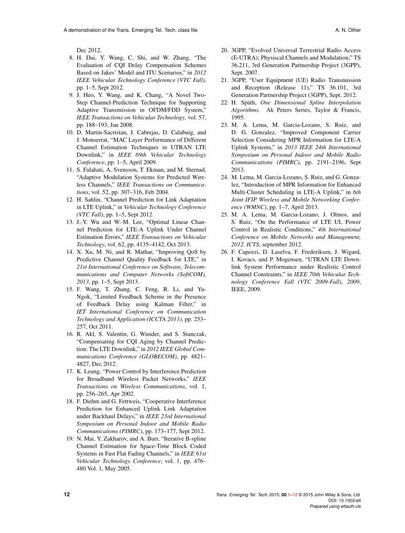
Figure 6. SINR evolution for two cell occupancies
In this regard, the PF scheduler provides more changeableallocations which influences the interference variability.
The variability in time of the interference generatedis highly impacted by the number of UEs having activeconnections at the eNB: the higher the number of UEs, themore variable the interference becomes. The probabilityof having always the same interferer source is loweras the number of connections increase. Figure 6 showsthe evolution of the SINR over time for two differenteNB occupancies. When the cell occupation is low, theinterference variation over time results in a less changeableSINR, while increasing the load in the cell leads toincreased variations of the SINR.
Due to the temporal variability of the SINR and theincreased delays in sounding experienced in high band-width transmissions, accurate CSI acquisition becomes
challenging. The main goal is to find a method to supportthe use of SRSs in high reporting interval situations,motivated by the use of CA, that is able to improve theCQI reliability under realistic interference situations.
5. PROPOSED SOLUTION
The fundamental idea behind the cubic spline is gettinga set of smooth curves through a number of predefineddata points [22], in this case the SINR measured frompreviously received SRS. So given a past observation timein the interval [a, b] = {a = x0 < x1 < · · · < xm = b},the SINR prediction function S(x) is a third order splineand satisfies the form:
S(x) =
s1(x) if x0 ≤ x < x1,
s2(x) if x1 ≤ x < x2,...sm(x) if xm−1 ≤ x < xm
(1)
where each si(x) is a third order polynomial defined by:
si(x) = ai(x− xi)3 + bi(x− xi)2 + ci(x− xi) + di.(2)
To calculate the unknown coefficients of the splinefunction 4 ·m equations are required. They can be posedconsidering the following properties:
1. S(x) must be contiguous on its entire interval,si(xi) = si+1(xi). This means that each polyno-mial goes through two consecutive data points,obtaining 2 ·m equations.
2. To make S(x) smooth across the intervals itsfirst and second derivative S′(x) S′′(x) are alsocontiguous. This results in 2 · (m− 1) equations.
3. Finally, the boundary conditions provide the twomissing equations. In this case a natural spline isassumed, S ′′(x0) = 0, S ′′(xm) = 0.
Figure 7 depicts the explained mathematical method.Figure 8 shows how the spline correctly matches anextended pedestrian B (EPB) channel model beyond oneround trip time (RTT) of 8 ms; the figure shows the channelimpulse response, where H is log
(|H|2
). This qualitative
6 Trans. Emerging Tel. Tech. 2015; 00:1–12 © 2015 John Wiley & Sons, Ltd.DOI: 10.1002/ett
Prepared using ettauth.cls

A. N. Other A demonstration of the Trans. Emerging Tel. Tech. class file
f1
f2
fm-1fi
fmf1
x1 x2 xi xm-1 xm
s1(x) si(x) sm-1(x)
f(x)
x
Figure 7. Cubic spline interpolation of data points.
Figure 8. Channel prediction cubic spline extrapolation
analysis shows a superior channel evaluation than justkeeping constant the last SRS information (SRS basedchannel on the plot). Note however, that interference isnot present yet. The squares indicate the reporting pointsor times in which the eNB receives an SRS from the UE,10 ms in this example. It is remarkable that no matterhow often SRS are received, if the user is allocated thatresource, it will be being used one RTT later in the bestcase, so at least that prediction horizon should be aimed.Since the PRB is the minimum allocable unit in LTE, theeNB just needs to compute a CQI per PRB or even smallsets of them, so an average among all the channels per sub-carrier is performed. The presence of interference yieldsa much noisier evolution of SRSs, so the resulting splineis expected to have sharper variations. Figure 9 shows anexample of prediction in case of a channel affected byinterference from users in neighbouring cells. It is evidenthow the presence of large interference variations from oneTTI to the next may imply that the spline is not ableto follow the channel and so wrong scheduling decisionscan be taken about the quality and suitability of particularPRBs. Moreover, in some cases the first derivative at thelast SRS reporting point can be very high and so theduration of the reliable prediction horizon is dramaticallyreduced. Hence, it is necessary to introduce a divergencedetection mechanism. The spline is considered to divergewhen variations higher than 10 dB occur in less than oneRTT, this simplistic heuristic is enough to filter out thosecases. Then the last prediction that was considered asreliable is kept fix until a new SRS update.
Figure 9. UE channel prediction based on cubic splineextrapolation, effect of low SINR.
6. SYSTEM MODEL
We consider a LTE-A UL system with CA, consisting ofC aggregated CCs. The criteria for selecting the UEs thatperform CA is based on their available power [23].
Consider a macro cell network with a set of J eNBs,each one has a total number I of active users. All CCs arein the same frequency band with the exact same bandwidth,and each one is comprised ofR PRBs which are allocatedto users each TTI. Each user, is assigned a user block uband a cyclic shift nm (wherem ∈M andM is the numberof multiplexed UEs). All UEs with the same ub share thesame allocation, therefore different cyclic shifts nm areassigned. The eNB allocates groups of successive resourceblocks to each user block; in one allocation process itdistributes the total bandwidth along all the user blocks.
Open loop power control (OLPC) expressed in equation3 determines the UE transmitted power for a CA systemconsidering non-contiguous resource allocation within oneCC; πA corresponds to the maximum power reduction(MPR) that is intrinsic to non-contiguous allocation,introduced to contain non-linearities of the power amplifier[24]; P0 and α are OLPC parameters [25] and L is the ULpath-loss.
PMCTX = min(Pmax − πA, P0 + 10 logMAlloc + α · L)
(3)The eNB allocates a set of MAlloc =MSRS contiguous
PRBs to be sounded and obtain a CQI measurement. Notethat to avoid further power reductions, no simultaneousSRS transmission in both CCs is considered, thereforewhen calculating the SRS transmission power, PSRS, πA isset to zero. The signal received per PRB r at the eNB sidein its cth CC and one RTT later is denoted as SUL
c,r (i, j).For the sake of simplicity subindex c has been omitted inall equations.
SULr (i, j) = PSRShr (i, j) d (i, j)
−α 10χ10 (4)
Where PSRS is the SRS transmit power, calculated withequation 3; hr (i, j) is the Rayleigh fading at PRB level;d (i, j) is the distance from user i to the eNB j and α is thepath loss exponent; χ is a Normal random variable withzero mean and standard deviation σ.
Trans. Emerging Tel. Tech. 2015; 00:1–12 © 2015 John Wiley & Sons, Ltd. 7DOI: 10.1002/ettPrepared using ettauth.cls

A demonstration of the Trans. Emerging Tel. Tech. class file A. N. Other
With this, the eNB can estimate the user’s i SINR atPRB r in carrier l as:
γSRSr (i, j) =
SULr (i, j)
Ir (i, j) + σ2n
(5)
where σ2n is the noise power and Ir is the total aggregate
inter-cell interference perceived in PRB r which ismodeled as:
Ir (i, j) =∑n∈N
PSRS,nhr (i, j) d (i, j) d (n, j)−α 10
χ10 (6)
whereN is the set of interfering UL users associated to theneighbouring cells.
The SINR in equation 5 is the one providing the CQIused by the eNB for transmission procedures. This valueof SINR is updated when a new SRS reporting is available,i.e. every Tsound.
Following this sounding process along the entire CC(all PRBs in R) lets to obtain a single value of γSRS
r (i, j)for every PRB. The scheduler’s main task is to allocateMAlloc =MPUSCH in order to maximize throughput whilemaintaining a proportional fairness in the coverage area.Based on the average γSRS (i, j) over the selected PRBs,the eNB signals the UL scheduling grant.
The received PUSCH signal one RTT later is:
SUL (i, j) = PMCTX h (i, j) d (i, j)
−α 10χ10 (7)
where PMCTX is obtained from the OLPC formula with
the corresponding maximum power reduction for CAallocations, following equation 3. The resulting SINR is:
γPUSCH (i, j) =SUL (i, j)
I (i, j) + σ2(8)
where I (i, j) is the average interference perceived inall MPUSCH. The interference in the PUSCH channel ismodelled as in the SRS channel.
From equations 5 and 8 it is inferred that a differencein both may arise: difference in interference perception,because sources of interference change with time, andalso differences in the received power due to the channelimpulse response evolution with time. The predictionmethod calculates the SINR γPUSCH (i, j) at the timeof reception tp = t+ 1RTT , where t is the schedulinginstant. In particular, the prediction horizon time span,with respect to the last SRS reporting instant, goesfrom tp = 1RTT , concurring with the SRS reception,to tp = Tsound − 1 + 1RTT, when the prediction horizoncorresponds to one TTI prior the arrival of the next SRS.
Finally, a simple successive IC process is consideredto clean the desired signal from the strong temporalvariations. The basic concept of this strategy is thatthe interference power can be reduced by decoding andsubsequently subtracting the interference signals. IC isapplied in both SRS and PUSCH received signals.
Table III. Simulation scenario assumptions
Parameter Value
Inter-site distance 500 m
Bandwidth 2 x 20 MHzPower delay profile Extended Pedestrian-B
Doppler model Young and Beaulieu 3 km/h
Shadowing correlation distance 50 m
Shadowing deviation 6 dB
BSRS 16 PRBs
Tsound 10 ms
Number of UEs served 10 and 15
Number of UEs connected 10 and 30
PRBs allocated 2 clusters of 2 PRBs x CC
Simulation time 10 kTTI
UE Buffer size 1 Mb
Round trip time 8 ms
Target BLER 10 %
Maximum UE transmission power 23 dBm
7. EVALUATION METHODOLOGY
The mechanism is evaluated in a highly realistic dynamicsystem level simulator which follows the guidelines in [1,21]. The simulation scenario is a macro-cell case with 14sites and 3 sectors per site. An EPB channel model is used,considering a UE speed of 3 km/h. Spatially correlatedlog-normal variations are introduced. 3D radiation patternsfrom commercial antennas have been used with 10◦
electric tilt adjustment. Two contiguous CCs of 20 MHzeach are configured, resulting in a total bandwidth of40 MHz. Link layer abstraction is performed with theclassic mutual information effective SINR mapping.
Users are uniformly random spread with finite buffersizes. Once the buffer is empty, the UE is automaticallyreconnected in a different part of the same cell, so thatthe number of connections remain constant. Uplink openloop power control parameters are adjusted following [25]and are equal for all eNB and CCs. Further details aboutsimulation assumptions are listed in Table III. Withthe aim of testing the proposed strategy under differentinterference situations three scenarios are studied:
• A low resource utilization (RU) scenario where10 UEs have an active connection to each cell and50% of the resources are actively used.
• Higher number of UEs, 30 have an activeconnection with 50% of the resources being activelyused.
• High number of active connections 30 UEs and 75%RU.
The allocated resources per UE remain constant on eachstudied scenario and the RU varies depending on thenumber of UEs that are allowed to access the scheduler.
8 Trans. Emerging Tel. Tech. 2015; 00:1–12 © 2015 John Wiley & Sons, Ltd.DOI: 10.1002/ett
Prepared using ettauth.cls

A. N. Other A demonstration of the Trans. Emerging Tel. Tech. class file
0 20 40
−15
−10
−5
0
5
time (ms)
H(d
B)
UE Channel
SRS samples
Cubic spline based channel
SRS based channel
(a) Cubic spline with 3 SRS samples
0 20 40
−15
−10
−5
0
5
time (ms)
H (
dB)
UE channel
SRS samples
Cubic spline based channel
SRS based channel
(b) Cubic spline with 5 SRS samples
0 20 40
−15
−10
−5
0
5
time (ms)
H (
dB)
UE channel
SRS samples
Cubic spline based channel
SRS based channel
(c) Cubic spline with 8 SRS samples
0 20 40
−15
−10
−5
0
5
time (ms)H
(dB
)
UE channel
SRS samples
Cubic spline based channel
SRS based channel
(d) Cubic spline with 10 SRS samples
Figure 10. Cubic spline construction with different number of SRS samples
There is a fixed number of UEs allocated by the frequencydomain scheduler at each TTI [26].
The selected method, cubic splines, is compared to alinear extrapolation method, in which the last two SRSsamples are used to calculate the future sample, and to thebaseline scenario, where the scheduler just uses the SINRat the last SRS for the allocation and link adaptation.
8. RESULTS AND DISCUSSION
8.1. Impact of Spline size
As explained in section 5, the piece-wise polynomialmethod needs SINR points measured from the SRS tointerpolate and construct the whole curve. The numberof past SRSs used for this purpose has an impact in theextrapolation result, figure 10 shows the curve constructionwith different number of sampling points.
The minimum number of points to construct a curve isthree, and as the number increases, more polynomials areconsidered in the cubic spline construction which leads todifferent results. The cubic spline depicted in the figureshows that the piece-wise curve achieves a maximumpoint, in which by adding more polynomials no differenceis recognised. In this study the spline construction achievesa state of no further change when more than 8 SRS samples
are considered, and this value is considered to conduct theperformance evaluation.
8.2. Error Distribution
The performance of the CSI acquisition methods areevaluated with the pdf of the SINR error, or misalignment.This error is measured as the difference between the SINRmeasured in the PUSCH transmission and the sounded orpredicted signal used for scheduling and link adaptation.Let recall that the prediction instant, or prediction horizon,can go from one RTT, in the case when the SRS has justbeen received in the current TTI, or Tsound − 1 + 1RTT inthe worst case.
Figure 11 shows the error of the CQI acquisition processin the presence of interference. In particular, it shows thepdf of the SINR error for the three interference scenariossimulated. Interference variations lead to strong errors inthe channel measurement; in all the scenarios evaluatedthe probability of error zero never surpasses 35% forthe baseline case, and predictions perform clearly worse.Under such conditions it is not possible to improve theCSI, because not even the SRSs are providing sufficientinformation to correctly reconstruct the SINR curve. Theinterference variability is the main limitation of the channelestimation based on prediction or sounding. In conditionswhere the UE is exposed to high interference variationsit is very difficult to predict the interference behaviour inthe forthcoming TTIs, the variability that the interference
Trans. Emerging Tel. Tech. 2015; 00:1–12 © 2015 John Wiley & Sons, Ltd. 9DOI: 10.1002/ettPrepared using ettauth.cls

A demonstration of the Trans. Emerging Tel. Tech. class file A. N. Other
- 6 - 4 - 2 0 2 4 60 , 00 , 10 , 20 , 30 , 40 , 5
S I N R e r r o r ( d B )
B a s e l i n eS p l i n eL . E
(a) 10 UEs and RU=50%
- 6 - 4 - 2 0 2 4 60 , 00 , 10 , 20 , 30 , 40 , 5
S I N R e r r o r ( d B )
B a s e l i n eS p l i n eL . E
(b) 30 UEs and RU=50%
- 6 - 4 - 2 0 2 4 60 , 0
0 , 1
0 , 2
0 , 3
0 , 4
S I N R e r r o r ( d B )
B a s e l i n eS p l i n eL . E
(c) 30 UEs and RU=75%
Figure 11. SINR error distribution for the different evaluated scenarios in normal interference conditions
- 6 - 4 - 2 0 2 4 60 , 00 , 20 , 40 , 60 , 81 , 0
S I N R e r r o r ( d B )
B a s e l i n eS p l i n eL . E
Figure 12. pdf of SNR error measurement.
causes to the SINR can have a dynamic range higher than10 dBs. In this sense, it is more profitable to maintain thepast value than to predict the SINR behaviour. However,the probability of error zero in this case is very low, despitethe cell occupancy and resource utilization.
8.3. Impact of Interference Cancellation
With the aim of improving the SRS information, and alsoto support predictions and obtain higher probability ofnull error, IC strategies are introduced. An initial studyof signal to noise ratio (SNR) prediction is representedin figure 12, where it shows that the prediction methodcan comfortably improve CSI. In this case, the numberof connections and the RU are irrelevant given that onlythe SNR is measured (i.e. no interference is considered).There is almost 20% of improvement in the null errorprobability with the use of splines, and also errors between-2 dB and 2 dB are reduced. This shows that there is a wideroom for improvement with the use of cubic splines, thatoutperform also the linear extrapolation case. However,the complete removal of interferences is complex and noIC receiver is capable of doing this, such an assumptionwould not be realistic. Therefore, an intermediate scenarioshall be encountered where the IC can provide significant
improvements to the SINR prediction and the CSIacquisition itself. Figure 13 shows the percentage of nullSINR error under different IC conditions. The interferencecancelled is expressed in terms of interference sources;information about the amount of dBs cancelled is notprovided since the most dominant interference sourceaffecting to the different UEs may have tenths of dBs ofdifference, hence, no absolute value of dBs level can beprovided.
From the figure, it is noted that each interferencescenario has a different minimum cancellation threshold.For instance, in the low load case if two sources arecancelled the cubic spline offers a 2% improvementover the baseline case, and this improvement boostsas the number of cancelled interferences grows. Thelinear extrapolation method provides poorer performancecompared to the polynomial solution, however it alsooffers some improvements as the interference variabilityis reduced. When the number of connections increaseand the RU is kept at 50%, three cancelled sources arenecessary to provide improvement with the spline method,and when the RU increases to 75% four sources are neededto be cancelled. This performance is expected, since thenumber of UEs connected and the RU affect directly to theinterference generation and variability.
It is interesting to note, that in all the interferencescenarios studied, for a number of cancellations higherthan two the baseline scenario does not offer muchimprovement and arrives to a saturation point, while inthe prediction case the improvement continues to grow.Apart from the interference impact, it is recognisedthat the baseline case presents an upper bound limit inits performance, which cannot be further improved byremoving sources of interference. In fact, the saturationpoint is not far from the performance obtained in theabsence of interference; this upper bound limit the SRShas is very much related to the sounding delay. Note thatthe divergence control mechanism added to the spline
10 Trans. Emerging Tel. Tech. 2015; 00:1–12 © 2015 John Wiley & Sons, Ltd.DOI: 10.1002/ett
Prepared using ettauth.cls

A. N. Other A demonstration of the Trans. Emerging Tel. Tech. class file
0 1 2 3 4
0 , 2
0 , 4
0 , 6
0 , 8
B a s e l i n eS p l i n eL . E
P(erro
r0dB
)
I C ( I n t e r f e r e r s s u p r e s s e d )(a) 10 UEs and RU=50%
0 1 2 3 4
0 , 2
0 , 4
0 , 6
0 , 8
P(erro
r0dB
)
I C ( I n t e r f e r e r s s u p r e s s e d )
B a s e l i n eS p l i n eL . E
(b) 30 UEs and RU=50%
0 1 2 3 4
0 , 2
0 , 4
0 , 6
0 , 8
B a s e l i n eS p l i n eL . E
P(erro
r0dB
)
I C ( I n t e r f e r e r s s u p r e s s e d )(c) 30 UEs and RU=75%
Figure 13. Probability of null SINR error versus the number of sources of interference cancelled
prediction method helps not to increase huge errors in theSINR prediction, and not to grow it more than the onealready provided by the SRS.
9. CONCLUSIONS
This paper has addressed one of the main problemsthat the UL of LTE-A may encounter when pursuinggood spectral efficiency and low BLER transmissions.Imperfect CSI acquisition and knowledge impairs thecorrect performance of other auspicious RRM algorithms,because it entails increased errors and retransmissions. TheUL channel presents two main challenges to improve theCQI accuracy, first, the ever-changing interference thatresults from variable scheduling decisions, and second,the delay in channel reporting. In LTE-A the UE sendsSRSs every sub-frame to provide a complete knowledgeof the SINR across the entire available band, andthis information is useful to support frequency domainscheduling decisions and accurate link adaptation. Thus,increased time-variations of the SINR values and largedelay between two consecutive measurement reports canbe detrimental for the correct UE performance.
With the aim of improving the SINR knowledge,this paper has proposed the use of a cubic splineextrapolation method that allows extending the SINRknowledge between the reception of two SRSs. Theproposed strategy can be applicable under realisticCSI acquisition conditions. It has been evaluated underdifferent interference situations and compared against thebaseline and other benchmark solutions. The cubic splineextrapolation method has shown room for improvementof the SINR misalignment when interference variability iskept low with the use of IC. It has been seen that the CSIacquisition can be severely damaged in high interferencevariability conditions, therefore, this would be a feasiblesolution only if a certain level of IC is performed. The level
of IC has been accordingly quantified, and the proposedsolution presents almost a linear improvement with respectto the level of interference cancelled, while in the baselinescenario it has been recognised an upper limit inflicted bythe SRS delay.
ACKNOWLEDGMENT
This work was supported by the Spanish National Science Council through the project TEC2014-60258-C2-2-R and by the European Regional Development Fund (ERDF) as well as an Ericsson 5G and Tactile Internet industry grant to King’s College London.
REFERENCES
1. 3GPP, “Physical Layer Procedures,” TS 36.213, 3rdGeneration Partnership Project (3GPP), Sept. 2009.
2. A. Ghosh and R. Ratasuk, Essentials of LTE and LTE-A. Cambridge University Press, 2011.
3. 3GPP, “Non-Contiguous UL Resource Allocation:Throughput Performance,” Tech. Rep. R1-091910,3GPP TSG-RAN, Jan. 2010.
4. 3GPP, “Necessity of Multiple Bandwidths forSounding Reference Signals,” Tech. Rep. R1-074807,3GPP TSG-RAN, Nov. 2007.
5. 3GPP, “SRS for Carrier Aggregation in LTE-Advanced,” Tech. Rep. R1-100458, 3GPP TSG-RAN, Jan. 2010.
6. M. Ni, X. Xu, and R. Mathar, “A Channel FeedbackModel with Robust SINR Prediction for LTESystems,” in 7th European Conference on Antennasand Propagation (EuCAP), pp. 1866–1870, IEEE,2013.
7. H. Dai, Y. Wang, K. Zhang, and C. Shi, “LinkAdaptation Algorithms for Channel Estimation ErrorMitigation in LTE Systems,” in Global Communi-cations Conference (GLOBECOM), pp. 1835–1840,
Trans. Emerging Tel. Tech. 2015; 00:1–12 © 2015 John Wiley & Sons, Ltd. 11DOI: 10.1002/ettPrepared using ettauth.cls
A demonstration of the Trans. Emerging Tel. Tech. class file A. N. Other
Dec 2012.8. H. Dai, Y. Wang, C. Shi, and W. Zhang, “The
Evaluation of CQI Delay Compensation SchemesBased on Jakes’ Model and ITU Scenarios,” in 2012IEEE Vehicular Technology Conference (VTC Fall),pp. 1–5, Sept 2012.
9. J. Heo, Y. Wang, and K. Chang, “A Novel Two-Step Channel-Prediction Technique for SupportingAdaptive Transmission in OFDM/FDD System,”IEEE Transactions on Vehicular Technology, vol. 57,pp. 188–193, Jan 2008.
10. D. Martin-Sacristan, J. Cabrejas, D. Calabuig, andJ. Monserrat, “MAC Layer Performance of DifferentChannel Estimation Techniques in UTRAN LTEDownlink,” in IEEE 69th Vehicular TechnologyConference, pp. 1–5, April 2009.
11. S. Falahati, A. Svensson, T. Ekman, and M. Sternad,“Adaptive Modulation Systems for Predicted Wire-less Channels,” IEEE Transactions on Communica-tions, vol. 52, pp. 307–316, Feb 2004.
12. H. Sahlin, “Channel Prediction for Link Adaptationin LTE Uplink,” in Vehicular Technology Conference(VTC Fall), pp. 1–5, Sept 2012.
13. J.-Y. Wu and W.-M. Lee, “Optimal Linear Chan-nel Prediction for LTE-A Uplink Under ChannelEstimation Errors,” IEEE Transactions on VehicularTechnology, vol. 62, pp. 4135–4142, Oct 2013.
14. X. Xu, M. Ni, and R. Mathar, “Improving QoS byPredictive Channel Quality Feedback for LTE,” in21st International Conference on Software, Telecom-munications and Computer Networks (SoftCOM),2013, pp. 1–5, Sept 2013.
15. F. Wang, T. Zhang, C. Feng, R. Li, and Yu-Ngok, “Limited Feedback Scheme in the Presenceof Feedback Delay using Kalman Filter,” inIET International Conference on CommunicationTechnology and Application (ICCTA 2011), pp. 253–257, Oct 2011.
16. R. Akl, S. Valentin, G. Wunder, and S. Stanczak,“Compensating for CQI Aging by Channel Predic-tion: The LTE Downlink,” in 2012 IEEE Global Com-munications Conference (GLOBECOM), pp. 4821–4827, Dec 2012.
17. K. Leung, “Power Control by Interference Predictionfor Broadband Wireless Packet Networks,” IEEETransactions on Wireless Communications, vol. 1,pp. 256–265, Apr 2002.
18. F. Diehm and G. Fettweis, “Cooperative InterferencePrediction for Enhanced Uplink Link Adaptationunder Backhaul Delays,” in IEEE 23rd InternationalSymposium on Personal Indoor and Mobile RadioCommunications (PIMRC), pp. 173–177, Sept 2012.
19. N. Mai, Y. Zakharov, and A. Burr, “Iterative B-splineChannel Estimation for Space-Time Block CodedSystems in Fast Flat Fading Channels,” in IEEE 61stVehicular Technology Conference, vol. 1, pp. 476–480 Vol. 1, May 2005.
20. 3GPP, “Evolved Universal Terrestrial Radio Access(E-UTRA); Physiscal Channels and Modulation,” TS36.211, 3rd Generation Partnership Project (3GPP),Sept. 2007.
21. 3GPP, “User Equipment (UE) Radio Transmissionand Reception (Release 11),” TS 36.101, 3rdGeneration Partnership Project (3GPP), Sept. 2012.
22. H. Spath, One Dimensional Spline InterpolationAlgorithms. Ak Peters Series, Taylor & Francis,1995.
23. M. A. Lema, M. Garcia-Lozano, S. Ruiz, andD. G. Gonzalez, “Improved Component CarrierSelection Considering MPR Information for LTE-AUplink Systems,” in 2013 IEEE 24th InternationalSymposium on Personal Indoor and Mobile RadioCommunications (PIMRC), pp. 2191–2196, Sept2013.
24. M. Lema, M. Garcia-Lozano, S. Ruiz, and G. Gonza-lez, “Introduction of MPR Information for EnhancedMulti-Cluster Scheduling in LTE-A Uplink,” in 6thJoint IFIP Wireless and Mobile Networking Confer-ence (WMNC), pp. 1–7, April 2013.
25. M. A. Lema, M. Garcia-Lozano, J. Olmos, andS. Ruiz, “On the Performance of LTE UL PowerControl in Realistic Conditions,” 4th InternationalConference on Mobile Networks and Management,2012. ICTS, september 2012.
26. F. Capozzi, D. Laselva, F. Frederiksen, J. Wigard,I. Kovacs, and P. Mogensen, “UTRAN LTE Down-link System Performance under Realistic ControlChannel Constraints,” in IEEE 70th Vehicular Tech-nology Conference Fall (VTC 2009-Fall), 2009,IEEE, 2009.
12 Trans. Emerging Tel. Tech. 2015; 00:1–12 © 2015 John Wiley & Sons, Ltd.DOI: 10.1002/ett
Prepared using ettauth.cls