Embed Size (px)
DESCRIPTION
Model 3185 Cub Cadet Operators Manual
Citation preview

IMPORTANT: READ SAFETY RULES AND INSTRUCTIONS CAREFULLY
Warning: This unit is equipped with an internal combustion engine and should not be used on ornear any unimproved forest-covered, brush-covered or grass-covered land unless the engine’sexhaust system is equipped with a spark arrester meeting applicable local or state laws (if any). If aspark arrester is used, it should be maintained in effective working order by the operator. In the Stateof California the above is required by law (Section 4442 of the California Public Resources Code).Other states may have similar laws. Federal laws apply on federal lands. A spark arrester for themuffler is available through your nearest engine authorized service dealer or contact the servicedepartment, P.O. Box 368023 Cleveland, Ohio 44136-9723.
CUB CADET P.O. BOX 368023 CLEVELAND, OHIO 44136-9723FORM NO. 770-0835B (9/98)
OPERATOR’S MANUAL
3000TRACTORModel 3185
2
SECTION 1: TABLE OF CONTENTSPAGE
IMPORTANT SAFE OPERATION PRACTICES . . . . . . . . . . . . . . . . . . . . . . 2SAFETY LABELS FOUND ON YOUR UNIT . . . . . . . . . . . . . . . . . . . . . . . . . 7TABLE OF CONTENTS. . . . . . . . . . . . . . . . . . . . . . . . . . . . . . . . . . . . . . . . . 2CALLING SERVICE INFORMATION . . . . . . . . . . . . . . . . . . . . . . . . . . . . . . 6FINDING YOUR MODEL & SERIAL NUMBER . . . . . . . . . . . . . . . . . . . . . . . 6CONTROLS. . . . . . . . . . . . . . . . . . . . . . . . . . . . . . . . . . . . . . . . . . . . . . . . . . 8OPERATION . . . . . . . . . . . . . . . . . . . . . . . . . . . . . . . . . . . . . . . . . . . . . . . . 12ADJUSTMENTS . . . . . . . . . . . . . . . . . . . . . . . . . . . . . . . . . . . . . . . . . . . . . 15MAINTENANCE . . . . . . . . . . . . . . . . . . . . . . . . . . . . . . . . . . . . . . . . . . . . . 17ENGINE INFORMATION. . . . . . . . . . . . . . . . . . . . . . . . . . . . . . . . . . . . . . . 25TROUBLE SHOOTING . . . . . . . . . . . . . . . . . . . . . . . . . . . . . . . . . . . . . . . . 31SPECIFICATIONS. . . . . . . . . . . . . . . . . . . . . . . . . . . . . . . . . . . . . . . . . . . . 33OPTIONAL EQUIPMENT . . . . . . . . . . . . . . . . . . . . . . . . . . . . . . . . . . . . . . 32QUICK REFERENCE PARTS . . . . . . . . . . . . . . . . . . . . . . . . . . . . . . . . . . . 34LUBRICATION ILLUSTRATION . . . . . . . . . . . . . . . . . . . . . . . . . . . . . . . . . 18SLOPE GAUGE. . . . . . . . . . . . . . . . . . . . . . . . . . . . . . . . . . . . . . . . . . . . . . 35LIMITED WARRANTY. . . . . . . . . . . . . . . . . . . . . . . . . . . . . . . . . . . . . . . . . 36
SECTION 2: IMPORTANT SAFE OPERATION PRACTICES
WARNING: THIS SYMBOL POINTS OUT IMPORTANT SAFETYINSTRUCTIONS WHICH, IF NOT FOLLOWED, COULD ENDANGERTHE PERSONAL SAFETY AND/OR PROPERTY OF YOURSELF ANDOTHERS.READ AND FOLLOW ALL INSTRUCTIONS IN THIS MANUALBEFORE ATTEMPTING TO OPERATE YOUR UNIT. FAILURE TOCOMPLY WITH THESE INSTRUCTIONS MAY RESULT IN PERSONALINJURY. WHEN YOU SEE THIS SYMBOL, HEED ITS WARNING.
WARNING: The Engine Exhaust from this productcontains chemicals known to the State of California to causecancer, birth defects or other reproductive harm.
DANGER: Your lawn mower was built to be operated according to therules for safe operation in this manual. As with any type of powerequipment, carelessness or error on the part of the operator can result inserious injury. This lawn mower is capable of amputating hands and feetand throwing objects. Failure to observe the following safety instructionscould result in serious injury or death.
1. GENERAL OPERATION• Read, understand, and follow all
instructions in the operator’s manualand on the machine before starting.Keep this manual in a safe place forfuture and regular reference and forordering replacement parts.
• Only allow responsible individualsfamiliar with the instructions tooperate the machine. Know controlsand how to stop the machinequickly.
• Do not put hands or feet undercutting deck or near rotating parts.

3
• Clear the area of objects such asrocks, toys, wire, etc., which couldbe picked up and thrown by theblade. A small object may havebeen overlooked and could beaccidentally thrown by the mower inany direction and cause injury toyou or a bystander. To help avoid athrown objects injury, keep children,bystanders and helpers at least 75feet from the mower while it is inoperation. Always wear safetyglasses or safety goggles duringoperation or while performing anadjustment or repair, to protect eyesfrom foreign objects. Stop theblade(s) when crossing graveldrives, walks or roads.
• Be sure the area is clear of otherpeople before mowing. Stopmachine if anyone enters the area.
• Never carry passengers.
• Disengage blade(s) before shiftinginto reverse and backing up. Alwayslook down and behind before andwhile backing.
• Be aware of the mower andattachment discharge direction anddo not point it at anyone. Do notoperate the mower without eitherthe entire grass catcher or the chuteguard in place.
• Slow down before turning. Operatethe machine smoothly. Avoid erraticoperation and excessive speed.
• Never leave a running machineunattended. Always turn off blade(s),place transmission in neutral, setpark brake, stop engine and removekey before dismounting.
• Turn off blade(s) when not mowing.
• Stop engine and wait until blade(s)comes to a complete stop before (a)removing grass catcher orunclogging chute, or (b) making anyrepairs, adjusting or removing anygrass or debris.
• Mow only in daylight or goodartificial light.
• Do not operate the machine whileunder the influence of alcohol ordrugs.
• Watch for traffic when operatingnear or crossing roadways.
• Use extra care when loading orunloading the machine into a traileror truck. This unit should not bedriven up or down a ramp onto atrailer or truck under power,because the unit could tip over,causing serious personal injury. Theunit must be pushed manually on aramp to load or unload properly.
• Never make a cutting heightadjustment while engine is running ifoperator must dismount to do so.
• Wear sturdy, rough-soled work shoesand close-fitting slacks and shirts. Donot wear loose fitting clothes orjewelry. They can be caught inmoving parts. Never operate a unit inbare feet, sandals, or sneakers.
• Check overhead clearance carefullybefore driving under power lines,wires, bridges or low hanging treebranches, before entering or leavingbuildings, or in any other situationwhere the operator may be struck orpulled from the unit, which couldresult in serious injury.
• Disengage all attachment clutches,thoroughly depress the brake pedal,and shift into neutral beforeattempting to start engine.
• Your mower is designed to cutnormal residential grass of a heightno more than 10". Do not attempt tomow through unusually tall, dry grass(e.g., pasture) or piles of dry leaves.Debris may build up on the mowerdeck or contact the engine exhaustpresenting a potential fire hazard.
• Use only accessories approved forthis machine by the manufacturer.Read, understand and follow allinstructions provided with theapproved accessory.

4
2. SLOPE OPERATIONSlopes are a major factor related toloss of control and tip-over accidentswhich can result in severe injury ordeath. All slopes require extra caution.If you cannot back up the slope or ifyou feel uneasy on it, do not mow it.For your safety, use the slope gaugeincluded as part of this manual tomeasure slopes before operating thisunit on a sloped or hilly area. If theslope is greater than 15° as shown onthe slope gauge, do not operate thisunit on that area or serious injurycould result.
DO:
• Mow up and down slopes, notacross.
• Remove obstacles such as rocks,limbs, etc.
• Watch for holes, ruts or bumps.Uneven terrain could overturn themachine. Tall grass can hideobstacles.
• Use slow speed. Choose a lowenough gear so that you will nothave to stop or shift while on theslope. Always keep machine in gearwhen going down slopes to takeadvantage of engine braking action.
• Follow the manufacturersrecommendations for wheel weightsor counterweights to improvestability.
• Use extra care with grass catchersor other attachments. These canchange the stability of the machine.
• Keep all movement on the slopesslow and gradual. Do not makesudden changes in speed ordirection. Rapid engagement orbraking could cause the front of themachine to lift and rapidly flip overbackwards which could causeserious injury.
• Avoid starting or stopping on aslope. If tires lose traction,disengage the blade(s) and proceedslowly straight down the slope.
DO NOT:• Do not turn on slopes unless
necessary; then, turn slowly andgradually downhill, if possible.
• Do not mow near drop-offs, ditchesor embankments. The mower couldsuddenly turn over if a wheel is overthe edge of a cliff or ditch, or if anedge caves in.
• Do not mow on wet grass. Reducedtraction could cause sliding.
• Do not try to stabilize the machineby putting your foot on the ground.
• Do not use grass catcher on steepslopes.
3. CHILDRENTragic accidents can occur if theoperator is not alert to the presence ofchildren. Children are often attractedto the machine and the mowingactivity. Never assume that childrenwill remain where you last saw them.
• Keep children out of the mowingarea and in watchful care of an adultother than the operator.
• Be alert and turn machine off ifchildren enter the area.
• Before and when backing, lookbehind and down for small children.
• Never carry children, even with theblades off. They may fall off and beseriously injured or interfere with thesafe machine operation.
• Never allow children under 14 yearsold to operate the machine. Children14 years and over should onlyoperate machine under closeparental supervision and properinstruction.
• Use extra care when approachingblind corners, shrubs, trees or otherobjects that may obscure your visionof a child or other hazard.

5
• Remove key when machine isunattended to prevent unauthorizedoperation.
4. SERVICE• Use extreme care in handling
gasoline and other fuels. They areextremely flammable and the vaporsare explosive.
• Use only an approved container.
• Never remove fuel cap or add fuelwith the engine running. Allowengine to cool at least two minutesbefore refueling.
• Replace fuel cap securely and wipeoff any spilled fuel before startingthe engine as it may cause a fire orexplosion.
• Extinguish all cigarettes, cigars,pipes and other sources of ignition.
• Never refuel the machine indoorsbecause fuel vapors will accumulatein the area.
• Never store the fuel container ormachine inside where there is anopen flame or spark, such as a gashot water heater, space heater orfurnace.
• Never run a machine inside a closedarea.
• To reduce fire hazard, keep themachine free of grass, leaves orother debris build-up. Clean up oil orfuel spillage. Allow machine to coolat least 5 minutes before storing.
• Before cleaning, repairing orinspecting, make certain the bladeand all moving parts have stopped.Disconnect the spark plug wire, andkeep the wire away from the sparkplug to prevent accidental starting.
• Check the blade and enginemounting bolts at frequent intervalsfor proper tightness. Also, visuallyinspect blade for damage (e.g.,excessive wear, bent, cracked).Replace with blade which meetsoriginal equipment specifications.
• Keep all nuts, bolts and screws tightto be sure the equipment is in safeworking condition.
• Never tamper with safety devices.Check their proper operationregularly. Use all guards asinstructed in this manual.
• After striking a foreign object, stopthe engine, remove the wire fromthe spark plug and thoroughlyinspect the mower for any damage.Repair the damage before restartingand operating the mower.
• Grass catcher components aresubject to wear, damage anddeterioration, which could exposemoving parts or allow objects to bethrown. For your safety protection,frequently check components andreplace with manufacturer’srecommended parts whennecessary.
• Mower blades are sharp and cancut. Wrap the blade(s) or weargloves and use extra caution whenservicing blade(s).
• Check brake operation frequently.Adjust and service as required.
• Muffler, engine and belt guardsbecome hot during operation andcan cause a burn. Allow to cooldown before touching.
• Do not change the engine governorsettings or overspeed the engine.Excessive engine speeds aredangerous.
• Observe proper disposal laws andregulations. Improper disposaloffluids and materials can harm theenvironment and the ecology.
• Prior to disposal, determine theproper method to dispose of wastefrom your local EnvironmentalProtection Agency. Recyclingcenters are established to properlydispose of materials in anenvironmentally safe fashion.

6
• Use proper containers whendraining fluids. Do not use food orbeverage containers that maymislead someone into drinking fromthem. Properly dispose of thecontainers immediately following thedraining of fluids.
• DO NOT pour oil or other fluids intothe ground, down a drain or into astream, pond, lake or other body ofwater. Observe EnvironmentalProtection Agency regulations whendisposing of oil, fuel, coolant, brakefluid, filters, batteries, tires and otherharmful waste.
WARNING - YOUR RESPONSIBILITY: Restrict the use ofthis power machine to persons who read, understand and follow thewarnings and instructions in this manual and on the machine.
SECTION 3: CALLING SERVICE INFORMATIONIf you have difficulties with the unit, have any question regarding the operationor maintenance of this equipment, or desire additional information not found inthis manual, contact your dealer. If you need help locating a dealer in your area,contact the Customer Dealer Referral Line by calling:
1-800-528-1009Before calling your local dealer, make sure that you have your model and serialnumbers ready.
SECTION 4: FINDING YOUR MODEL & SERIAL NUMBERThis Operator’s Manual is an important part of your new tractor. It will help youprepare, maintain and safely operate your tractor. Please read and understandwhat it says.Before you start to prepare your tractor for its first use, please locate the modelplate and copy the information from it into the space provided in this Operator’sManual. The information on the model plate is very important if you need helpfrom your dealer or the Cub Cadet customer support department.
• Every tractor has a model plate. The model plate is located on the right framerail behind the right front tire. See Figure 1.
Figure 1 • The engine identification numbers appear on a decal (or decals) affixed to the
engine shrouding. Record your engine identification numbers below:
CUB CADET CORP.P.O. BOX 368023
CLEVELAND, OHIO 44136
Model Number Mfg. Date
XXXXXXXXXXX XXXXXXXXXX
Model Number
Mfg. Date (Serial No.)
MODEL NO. TYPE NO. CODE NO.

7
SECTION 5: SAFETY LABELS FOUND ON YOUR UNIT
Figure 2
IGNITION STOP
STARTING INSTRUCTIONS1. BE FAMILIAR WITH CONTROLS
BEFORE STARTING ENGINE AND OPERATING.
2. SET CHOKE, MOVE THROTTLE TO MID POSITION AND DEPRESS BRAKE PEDAL.
3. TURN KEY TO THE START POSITION.
4. AFTER ENGINE STARTS OPEN CHOKE.
1. DISENGAGE PTO AND SET PARKING BRAKE.
2. MOVE THROTTLE CONTROL TO MID POSITION AND TURN KEY OFF.
POSITIONINDICATOR
• GO UP AND DOWN S L O P E S , N OT A C R O S S .• AVO I D S U D D E N T U R N S.
• D O N OT OP E R ATE U N IT W H E R E I T C O U L D S L I P O R T I P.
• I F M AC H I N E S TO P S G O I N G UPHILL, STOP PTO A N D B AC K D OW N H I L L S LOWLY.
• DO NOT MOW WHEN C H I L D R E N O R OT H E R S A R E A RO U N D.
• NEVER CARRY CHILDREN.
• L O O K D OW N A N D B E H I N D B E F O R E A N DW H I L E B AC K I N G
• K E E P S A F E T Y D E V I C E S [ G U A R D S , S H I E L D S , A N D S W I T C H E S ] I N P L A C E A N D W O R K I N G .
• REMOVE OBJECTS THAT C O U L D B E T H R OW N B Y T H E B L A D E S.
• K N O W L O C AT I O N A N D FUNCTION OF ALL CONTROLS.
• BE SURE THE BLADES AND THE ENGINE ARE STOPPED BEFORE PLACING HANDS O R F E E T N E A R B L A D E S.
• B E F O R E L E AV I N G O P E R ATO R ' S P O S IT I O N , DISENGAGE PTO, ENGAGE BRAKE LOCK, SHUT OFF ENGINE AND REMOVE KEY.
AVOID SERIOUS INJURY OR DEATH
READ OPERATOR'S MANUAL
WARNING
STOPPING INSTRUCTIONS

8
SECTION 6: CONTROLS
Figure 3
ABCDEFGHI
JKLMNOPQ
Parking Brake LeverPTO SwitchBrake PedalReverse PedalForward PedalIgnition/Light SwitchCenter Lift Height IndicatorTransmission Release RodTransmission Oil Fill /Dipstick
Fuel Fill CapCup HolderHydraulic Lift LeverSteering Wheel Tilt LockCruise Control LeverChoke LeverThrottle LeverSeat Adjustment Lever (Not Shown)
* Steering Wheel and Seat Removed For Clarity
A
B
C
D
E
F
G
H
I
J
K
L
M
N
O
P
Q
R
(Not Shown)
R Indicator Light Pod

9
NOTE: References to LEFT andRIGHT indicate that side of the tractorwhen facing forward while seated inthe drivers seat. Reference to FRONTindicates the grille end of the tractor;to REAR, the drawbar end.
Steering WheelThe steering wheel is centered on thedash panel. It is used to change thedirection (left or right) of the tractorwhile driving.
NOTE: This tractor is equipped withpower steering. Because of thisfeature, the steering wheel might notbe center aligned.
Parking Brake Lever
Figure 4
The parking brake lever is located tothe right of the steering wheel on thedash panel. With the brake pedaldepressed fully, push the parkingbrake lever and release the brakepedal to lock the parking brake.
PTO SwitchThe PTO switch is located on the rightside the dash panel. Pull upward onthe right edge of the switch handle toengage the PTO clutch. Push theswitch downward to disengage thePTO clutch.
Brake Pedal
Figure 5
The brake pedal is located at the frontof the right running board above theforward and reverse pedals. Pressdown to stop the tractor and
disengage the cruise control. Thebrake pedal must be fully depressed toactivate the safety interlock switchwhen starting the tractor.
Reverse Pedal
Figure 6
NOTE: Check behind the tractor tobe sure the area is clear of people,pets or obstacles and use a slowerspeed to maintain control of the tractorwhen traveling in reverse.
The reverse control pedal is locatedon the right running board below thebrake pedal. Press the pedal down tomove in reverse.
Forward Pedal
Figure 7
The forward control pedal is locatedon the right running board below thebrake pedal. Slowly press down on thepedal to start moving forward. Theforward ground speed of the tractor isdirectly affected by the distance thepedal is depressed.
Deck Front Lift Rod Assembly
For shipping purposes, the deck frontlift rod assembly has been installed onthe tractor. Cut the tie strap holdingthe lift rod assembly to the tractor;then pull downward on the quick latchrod at the front of the tractor to removethe lift rod assembly.

10
Ignition / Light SwitchTo prevent accidental starting and/orbattery discharge, remove the keyfrom the ignition switch when thetractor is not in use. The combinationlights and ignition switch has fourpositions. See Figure 8 for adescription of each position.
Figure 8
Center Lift Height IndicatorThe center lift height indicator islocated in the left running board. Thisindicator shows the operator therelative height position setting of thehydraulic center lift system. The lowernumber indicates a lower setting.
Transmission Release RodThe transmission release rod islocated at the back of the tractor in thedraw bar. This rod, when engaged,allows the tractor to be pushed shortdistances by hand. To disengage the transmission, pullback on the rod until its locking flangeis visible outside the drawbar, then liftthe rod up into the slot and release. Toreengage the transmission, pull backon the rod, drop out of the slot andrelease.
Transmission Oil Fill/DipstickThe transmission oil fill/dipstick islocated at the back of the tractor in therear draw bar. The handle of the trans-
mission oil dipstick serves as the filltube plug and should fit snugly in thefill tube.
Fuel Fill CapThe fuel fill cap is located on thefender to the left of the seat.
Cup HolderThe cup holder is located on thefender to the left of the seat.
Hydraulic Lift LeverThe hydraulic lift lever is located onthe fender to the left of the seat. Thislever is used to operate the tractor’scenter lift system.
Steering Wheel Tilt LockThe steering wheel tilt lock is locatedunder the steering wheel on the dashpanel.
Cruise Control Lever
Figure 9
The cruise control lever is located tothe left of the steering wheel. Push thecruise control lever downward whiletraveling at the desired forward speedto engage the cruise control.
Choke LeverThe choke lever is located to the left ofthe steering wheel in the throttle/chokelever pod. Push the lever forward toclose the engine choke plate.
Throttle Lever
OffOn/Lights
On
Start
This symbol shows the fast
This symbol shows the slow
position.
position

11
The throttle lever is located to the leftof the steering wheel in the throttle/choke lever pod. This lever controlsthe speed of the engine. Push thelever forward to increase the enginespeed. When set in a given position,the throttle will maintain a uniformengine speed.
IMPORTANT: When using powertake-off operated equipment, bestperformance is achieved with thethrottle lever in the “FAST” position.
Seat Adjustment LeverThe seat adjustment lever is locatedbelow the seat. This lever is used toadjust the seat forward or back. Referto Figure 12 on page 15.
Indicator Light Pod
Figure 10
AB C D
E
ABC
DE
Oil Pressure IndicatorLow Fuel IndicatorHour Meter
Not UsedBattery Charge Indicator
Hour MeterThe hour meter is part of the indicatorlight pod in the dash panel. The hourmeter operates whenever the ignitionswitch is in the “ON” or “ON/LIGHTS”position. Record the actual hours of trac-tor operation to ensure all maintenanceprocedures are completed according tothe schedule in this manual.
Oil Pressure IndicatorWARNING: Operating thetractor with low oil level orpressure could result insevere engine damage.
The oil pressure indicator is part of theindicator light pod on the dash panel.This indicator will illuminate when theengine oil pressure is low. If thisindicator illuminates, stop the tractor
immediately and check the engine oillevel. If the oil level is within theoperating range, and the light remainson, contact your Cub Cadet dealer.
Low Fuel IndicatorThe Low Fuel indicator is part of theindicator light pod on the dash panel.This indicator will illuminate when thetractor is low on fuel. If the gas tank isfull and the light stays on, contact yourCub Cadet dealer.
Battery Charge IndicatorThe battery charge indicator is part ofthe indicator light pod on the dashpanel. This indicator will illuminatewhen the tractor’s voltage sensorreads low battery voltage. If the lightstays on, contact your Cub Cadetdealer.

12
SECTION 7: OPERATIONSafety Interlock SwitchesThis tractor is equipped with a safetyinterlock system for the protection ofthe operator. If the interlock systemshould ever malfunction, do notoperate the tractor. Contact yourauthorized Cub Cadet Dealer. Thesafety interlock system prevents theengine from cranking or startingunless the brake pedal is fullydepressed, and the PTO is “OFF”.
• The safety interlock system willautomatically shut off the engine ifthe operator leaves the seat beforeengaging the brake lock.
• The safety interlock system willautomatically shut off the engine ifthe operator leaves the seat with thePTO “ON”, regardless of whetherthe brake lock is engaged. The PTOswitch must be “OFF” to restart theengine.
• The safety interlock system willautomatically shut off the PTO if thereverse control pedal is depressedwith the PTO “ON”.
Fueling The TractorNOTE:Some fuels, called oxygen-ated or reformulated gasolines, aregasoline blended with alcohols orethers. Excessive amounts of theseblends can damage the fuel system orcause performance problems. Do notuse gasoline which contains Metha-nol. If any undesirable operatingsymptoms occur, use gasoline with alower percentage of alcohol or ether.Do not fill the fuel tank when theengine is running or while the engineis hot. Tighten the fuel cap securely.This engine is certified to operate onunleaded gasoline. Fill the fuel tankwith only clean, fresh, unleaded gaso-line with a minimum of 85 octane. Donot mix oil with gasoline. Purchase
fuel in a quantity that can be usedwithin 30 days to assure fuel fresh-ness. In countries other than theU.S.A., leaded gasoline may be usedif it is commercially available andunleaded is not available.
The fuel fill point is located on thefender to the left of the seat. Unscrewthe fuel cap and fill tank from anapproved gasoline container.
Starting The Engine• Operator must be sitting in the
tractor seat.
• Push choke lever to the full chokeposition. Less choking may benecessary due to variations intemperature, grade of fuel, etc. Littleor no choking will be needed whenthe engine is warm.
• Place the throttle midway betweenthe “SLOW” and “FAST” position.
• Make sure the PTO switch is in the“OFF” position.
• Fully depress the brake pedal.
• Turn the ignition key clockwise tothe “START” position and release itas soon as the engine starts;however, do not crank the enginecontinuously for more than 10seconds at a time. If the enginedoes not start within this time, turnthe key to “OFF” and wait a minuteto allow the engine’s starter motor tocool. Try again after waiting.
• After the engine starts, slowlyrelease the brake pedal. As theengine warms up, gradually pull thechoke lever all the way back. Do notuse the choke to enrich the fuelmixture, except when necessary tostart the engine.
Stopping The EngineNOTE: Remove the key from theignition switch to prevent accidentalstarting or battery discharge if theequipment is left unattended.

13
• Place the PTO switch in the “OFF”position. Move the throttle controllever to the “MID” position. Thenturn the ignition key to the “OFF”position.
• Remove the key from the ignitionswitch.
Driving The Tractor
WARNING: Avoid suddenstarts, excessive speed andsudden stops.
WARNING: Do not leavethe seat of the tractorwithout disengaging thePTO, depressing the brakepedal and engaging theparking brake. If leaving thetractor unattended, alsoturn the ignition key off andremove the key.
• Depress the brake pedal to releasethe parking brake and let the pedalup. Move the throttle lever to theposition where the engine operatesbest for the load to be handled(normally full throttle).
NOTE: Do not use the forward orreverse control pedals to change thedirection of travel when the tractor is inmotion. Use the brake pedal to bringthe tractor to a stop before depressingeither the forward or reverse controlpedal.
• To move forward, slowly depressthe forward control pedal until thedesired speed is achieved.
• To move in reverse, check that thearea behind is clear then slowlydepress the reverse control pedal.
Setting The Cruise ControlNOTE: The cruise control featurecan only be operated in the forwarddirection.
• Slowly depress the forward controlpedal until the desired speed isachieved.
• Lightly push the cruise control leverdownward.
• While continuing to hold the cruiselever down, lift your foot from theforward control pedal (you shouldfeel the cruise latch engage).
• If properly engaged, the cruise leverand forward control pedal shouldlock in the down position, and thetractor will maintain the sameforward speed.
• Disengage the cruise control usingone of the following methods:
- Depress the brake pedal todisengage the cruise controland stop the tractor.
- Lightly depress the forwardcontrol pedal.
- Lift the cruise control leverupward.
NOTE: Although not recommended,depressing the reverse pedal will alsodisengage the cruise control.
To change to the reverse directionwhen operating with cruise control,depress the brake pedal to disengagethe cruise control and stop the tractor;then depress the reverse control pedal.
Driving On SlopesRefer to the SLOPE GAUGE on page35 to help determine slopes where youmay not operate safely.
WARNING: Do not mowon inclines with a slope inexcess of 15 degrees (a riseof approximately 2-1/2 feetevery 10 feet). The tractorcould overturn and causeserious injury.
Operate the tractor up and downslopes, never across slopes. Do notdrive so that the tractor may tip oversideways
14
Before operating the tractor on anyslope, walk the slope to look forpossible hazards such as rocks.mounds, ruts, stumps or other surfaceirregularities which could cause thetractor to be upset.Back the tractor with attachment upthe steepest portion of each slope youintend to work. If the tractor cannotnegotiate the slope in reverse, theslope is too steep to be worked.Avoid turns when driving on a slope. Ifa turn must be made, turn down theslope. Turning up a slope greatlyincreases the chance of a roll over.Avoid stopping when driving up aslope. If it is necessary to stop whiledriving up a slope, start up smoothlyand carefully to reduce the possibilityof flipping the tractor over backward.
Stopping The TractorFully depress the brake pedal to bringthe tractor to a complete stop, engagethe parking brake, disengage thePTO, turn the ignition switch to “OFF’”and remove the key from the switchbefore dismounting.
Using the Hydraulic Lift SystemTo raise an attachment using thehydraulic lift system, the engine mustbe running. Generally, an attachmentcan be lowered with the enginerunning or off. Push the hydraulic liftlever forward to lower an attachmentor pull the hydraulic lift lever back toraise an attachment.
Opening Tool BoxA convenient tool box and manualpouch is located under the seat. Toaccess this area, pivot the seatforward.
Engaging The PTO• Move the throttle control lever to
approximately the mid throttleposition.
• Pull the PTO switch to the “RUN”position.
• Advance the throttle lever to theoperating speed (full engine speed).
• The operator must remain in thetractor seat at all times. If theoperator should leave the seatwithout turning off the power take-off switch, the tractor’s engine willshut off.
IMPORTANT: The PTO clutchcannot be operated when the tractor isdriving in the reverse direction. ThePTO switch must in the “OFF” positionwhen the reverse control pedal isdepressed, or the PTO clutch willautomatically disengage. To re-engage the PTO clutch, release thereverse control pedal, move the PTOswitch to the “OFF” position, thenagain pull the switch to the “RUN”position.
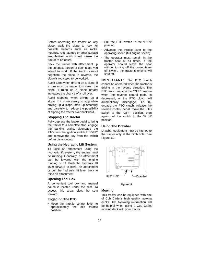
Using The DrawbarDrawbar equipment must be hitched tothe tractor only at the hitch hole. SeeFigure 11.
Figure 11
MowingThis tractor can be equipped with oneof Cub Cadet’s high quality mowingdecks. The following information willbe helpful when using a Cub Cadetmowing deck with your tractor.
DrawbarHitch Hole

15
WARNING: To avoid possi-ble injury, do not allow anyonein the area opposite the dis-charge chute while mowing.Although the area has beensupposedly cleared of foreignobjects, small objects may bepicked up and discharged bythe mower.
WARNING: Never directthe discharge of materialtoward bystanders or allowanyone near the machinewhile in operation.
For best results it is recommendedthat the first two laps should be cutwith the discharge thrown towards thecenter. After the first two laps, reversethe direction to throw the discharge tothe outside for the balance of cutting.This will give a better appearance tothe lawn.
Do not cut the grass too short, as themower will tend to scalp the grass.Short grass invites weed growth andyellows quickly in dry weather. Mowing should be done with theengine at full throttle. Do not mow athigh ground speed.During certain times of the year andunder some conditions, the mowermay leave streaks of uncut grass.Streaking may occur when attemptingto mow heavy weeds and tall grass.Under these conditions it may benecessary to go back over the cutarea a second time to get a clean cut.The following practices will helpeliminate streaking:
• Mow the area more often so thegrass doesn’t get too tall and heavy.
• Operate the tractor at full throttleand slower forward speeds.
• Keep the blades sharp and replacethe blades when worn.
SECTION 8: ADJUSTMENTS
Seat AdjustmentWARNING: Do not adjustthe seat when the tractor ismoving. Adjusting the seatwhile the tractor is movingcould cause the operator tolose control of the tractor.
To allow for the comfort of theoperator, an easy to operate adjustableseat is a feature of this tractor. Toadjust the seat forward or back, slidethe seat adjustment lever to the leftand reposition the seat to the desiredlocation. Once you have found acomfortable position, release the seatadjustment lever. See Figure 12.
Figure 12
Seat Adjustment Lever

16
Steering Wheel Tilt Adjustment
WARNING: Do not adjustthe steering wheel when thetractor is moving. Adjustingthe steering wheel while thetractor is moving couldcause the operator to losecontrol of the tractor.
To allow for the comfort of theoperator, an easy to operateadjustable steering wheel is a featureof this tractor. To adjust the steeringwheel forward or back, push down onthe steering wheel tilt lock lever andeither push or pull the steering wheelto the desired position. Once you havefound a comfortable position, releasethe steering wheel tilt lock lever.
Front Wheel Alignment
Note: The left-hand ball joint is left-hand threaded. The right-hand balljoint is right-hand threaded.
The front wheels should toe-in approx-imately 1/8 inch. Measure distances Aand B. A should be approximately 1/8inch less than B. See Figure 13.
Figure 13 To adjust toe-in loosen left and rightball joint jam nuts. See Figure 14.
Turn the tie rod in or out of ball jointsas required. Tighten the jam nutsagainst the ball joints.
Check for proper adjustment andreadjust as necessary.
Figure 14
Brake Inspection and Adjustment
During the normal operation of thetractor, the brakes are subject to wearand will require inspection andadjustment.
Figure 15
NOTE: Figure 15 is shown with theright rear wheel removed for clarity.Although not necessary for adjust-ment , removal of the wheels will easethe checking procedure.
Using a set of feeler gauges, completethe following procedure to check andadjust the brakes:
NOTE: The outer brake pad must bepulled against the rotor when thefeeler gauge is inserted between theinner pad and rotor.
A
B
Steering AxleHex Lock Nut
Ball Joint
Hex Jam NutTie Rod
BrakeAdjustment
Nut
BrakeRotor
Outer Brake Pad
Max. TotalClearance.030-.060
InnerBrakePad

17
• With the brake pedal disengaged,insert an .030” feeler gauge betweenthe inner brake pad and the rotor. Ifthe .030” gauge does not fit, thebrakes are overly tightened andshould be loosened.
• Attempt to insert an .060” feelergauge between the inner brake padand the rotor. The .060” clearanceis maximum allowable clearanceand insertion of the gauge shouldnot be possible.
• If the .060” gauge can be insertedthe brake must be tightened.
• Accessing the brake adjustment nutfrom the rear of the tractor, beneaththe fender, turn the nut clockwise to
tighten and counterclockwise toloosen the brake assembly. See Fig-ure 15.
• Turn the adjustment nut as neces-sary to obtain the .030” to .060”clearance.
• Repeat the above procedure tocheck and adjust the other brakeassembly as necessary.
Turning Radius Adjustment
This tractor is equipped with powerassisted steering which is set at thefactory. The turning radius should beequal for both left and right hand turns.If adjustment is necessary please con-tact your authorized Cub Cadet dealer.
SECTION 9: MAINTENANCEMaintenance Chart
‡ Change oil and filter after first 8 hours† More often under dusty conditions
†† Clean every 25 hours or more often under dusty or dirty conditions
Eac
h U
se
50 H
ou
rs
100
Ho
urs
150
Ho
urs
200
Ho
urs
250
Ho
urs
300
Ho
urs
Grease front wheel bearings •
Grease L/R steering knuckles •
Grease front pivot axle •
Check engine oil level •
Change engine oil and filter ‡ • • • • • •
Check transmission oil level •
Change transmission oil filter • • • • •
Change transmission oil • •
Check air cleaner & housing •
Clean & re-oil foam air pre-cleaner
††
Change air cleaner paper cartride
† † †
18
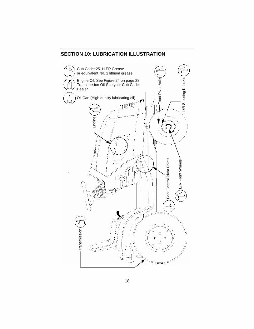
SECTION 10: LUBRICATION ILLUSTRATION
Cub Cadet 251H EP Greaseor equivalent No. 2 lithium grease
Engine Oil: See Figure 24 on page 28Transmission Oil-See your Cub Cadet
Oil Can (High quality lubricating oil)
DealerE
ngin
e
Fro
nt P
ivot
Axl
e
L/R
Ste
erin
g K
nuck
leL
/R F
ront
Whe
els
Foo
t Con
trol
Piv
ot P
oint
s
Tra
nsm
issi
on

19
Accessing Engine CompartmentThe engine compartment can beaccessed by lifting the hood upwardfrom the recessed notches of the sidepanels and tipping the hood forward. Ifgreater access is required, the tractoris equipped with quick release side
panels. To remove the quick releaseside panels (see Figure 16):• Open the hood by pulling up.• Flip quick release fasteners up and
turn to align with slots in side panels.• Swing the side panel out and away
from the tractor
Figure 16
Turn
Flip up
Lift Hood HereQuick Fasteners
General Battery Information
• Battery acid must be handled withgreat care, as contact with it canburn and blister the skin. It isadvisable to wear protective clothing(goggles, rubber gloves and apron)when working with acid.
• Should battery acid accidentallysplatter into the eyes or onto theskin, rinse the affected areaimmediately with clean cold water. Ifthere is any further discomfort, seekprompt medical attention.
• If acid spills on clothing, first dilute itwith clean water, then neutralizewith a solution of ammonia/water orbaking soda/water.
• Since battery acid is corrosive, do notpour it into any sink or drain. Beforediscarding an empty electrolyte con-
tainer, rinse it thoroughly with aneutralizing solution.
• NEVER connect (or disconnect)battery charger clips to the batterywhile the charger is turned on, as itcan cause sparks.
• Keep all sources of ignition(cigarettes, matches, lighters) awayfrom the battery. The hydrogen gasgenerated during charging can becombustible.
• As a further precaution, only chargethe battery in a well ventilated area.
• Always shield eyes and protect skinand clothing when working nearbatteries.
WARNING: Batteries containsulfuric acid and may emitexplosive gases. Useextreme caution when han-dling batteries. Keepbatteries out of the reach ofchildren.
WARNING

20
Battery RemovalThe battery is located under the dashpanel in the frame pedestal.To remove the battery:• Open the tractor hood by lifting it at
the notches in the side panels.• Remove the upper baffle of the
bulkhead from the front of the dashpanel by lifting upward on thelocking tab on each side of thebaffle.
• Pull the upper end of the rubberbattery strap rearward to unhook itfrom the tab on the pedestal.
• Loosen the negative battery cableclamp and disconnect the negativelead from the battery first; thendisconnect the positive lead fromthe battery.
• Carefully lift the battery up and outof the tractor.
Install the battery by repeating theabove steps in the reverse order.Always connect the positive lead tothe battery before connecting thenegative lead.
Battery MaintenanceThe battery is filled with battery acidand then sealed at the factory.However, even a “maintenance free”battery requires some maintenance toensure its proper life cycle.• Spray the terminals and exposed
wire with a battery terminal sealer,orcoat the terminals with a thin coatof grease or petroleum jelly, toprotect against corrosion.
• The battery should be kept clean.Any deposits of acid should beneutralized with baking soda andwater. Be careful not to get thissolution in the cells.
• Avoid tipping the battery. Even a“sealed” battery will leak electrolytewhen tipped.
Battery Storage• When storing the tractor for extended
periods, disconnect the battery
cables. Removing the battery fromthe unit is recommended.
• All batteries discharge duringstorage. Keep the exterior of thebattery clean, especially the top. Adirty battery will discharge itselfmore rapidly.
• The battery must be stored with afull charge. A discharged battery willfreeze at a higher temperature.
Specific Gravity Freezing Point1.265 –71°F1.250 –62°F1.200 –16°F
1.150 5°F1.100 16°F
• Recharge the battery beforereturning to service; or every twomonths, whichever comes first.
Headlight Bulb Replacement
Figure 17
The headlight assembly has two bulbsone for the right and one for the leftreflector. To replace one or bothheadlight bulbs:
Wire Harness
Locking Tab Locking Tab
Light Bulb Assembly

21
• Lift the hood to expose the backside of the headlight assembly.
• Pull both locking tabs away fromlight bulb and pull wire harnessaway. See Figure 17.
• Remove the light bulb from thereflector by turning counterclock-wise. The light bulb will be free ofthe reflector when the notches inthereflector and the tabs on the bulbare aligned.
• Replace light bulb with like part.
• Align the tabs on the light bulb andthe notches in the reflector andinsert light bulb.
• Turn light bulb clockwise to lock inplace. Connect wire harness andmake sure that the locking tabs areseated on the light bulb.
Tail Light Bulb Replacement
Each tail light assembly has twolightbulbs. Access the back side of thetail lights from under the rear fender.NOTE: Because of the close proximityof the fuel tank, extreme cautionshould be taken when removing thetail light sockets from the reflectorhousings. The bulbs can be pulledfrom the sockets and dropped into thereflector housing, which will thenrequire removal of the reflectorhousing to retrieve the bulb.
To replace a light bulb:
• Turn the light bulb socketcounterclockwise to align the tabson the socket with the notches inthe tail light reflector.
• Once aligned pull light socket out ofthe tail light reflector.
• Pull the light bulb from the socket.• Replace light bulbs with like part.• Align the tabs of the socket with the
notches in the reflector and carefullyinsert the socket.
• Turn socket clockwise to lock inplace. Make sure the socket islocked securely in place.
Tire InflationKeep the pneumatic tires properlyinflated. Over-inflation will causeoperator discomfort. Under-inflationwill cause short tire life.Improperly inflated tires will also affectthe level of the mower deck andquality of cut.See the tire side wall for properinflation range.Always ensure that the tire valve capsare in place and tightened securely toprevent loss of air and to protect thevalve core and stem.Do not overload the tractor tires bymounting equipment on the tractorwhich exceeds the load capacity of thesize of the tires on the tractor.
Checking Transmission Oil Level
Figure 18
NOTE: Check the oil level only whilethe engine is stopped and the tractor islevel.
TransmissionOil Fill Tube/
Dipstick
F
A
OperatingRange
Dipstick Reading

22
Check the oil level of the transmissioncase before each use to see that it isfilled to the correct level. Beforechecking the transmission oil level,clean the area around the Transmis-sion Oil Fill /Dipstick to prevent debrisfrom entering the transmission case.Always keep the oil level between the“FULL” and the “ADD” marks on thedipstick. When checking the oil level,the dipstick must be withdrawn andwiped clean, then reinserted all theway before being withdrawn again fora true reading.
Adding Transmission Oil
WARNING: Never overfill thetransmission case. Damagemay result if the oil level inthe transmission case isbelow the “ADD” mark orover the “FULL” mark of thedipstick.
For best results, fill to the “FULL” markon the dipstick as opposed to adding agiven quantity of oil. Always check thelevel on the dipstick before addingmore oil. See Figure 18.Refer to the Lubrication Illustration forinformation regarding the proper typeof oil to add to the transmission case.See the Specifications Chart for thequantity required.• Place the tractor on a level surface
and engage the parking brake. Stopthe tractor engine and remove theignition key.
• Clean the area around theTransmission Oil Fill /Dipstick toprevent debris from entering thetransmission case.
• Remove the dipstick from the oil filltube and SLOWLY pour oil into theoil fill tube. Fill the transmissioncase until the oil level reaches the“FULL” mark on the dipstick.
• Reinstall the dipstick securely intothe oil fill tube.
WARNING: The oil fill plug/dipstick must be installedsecurely into the fill tube atall times when the engine isoperating.
Changing Transmission Oil
Refer to the maintenance chart forinformation regarding the frequency ofservice.Refer to the Lubrication Illustration forinformation regarding the proper typeof oil to add to the transmission case.See the Specifications Chart for thequantity required.• Place the tractor on a level surface
and engage the parking brake. Stopthe tractor’s engine and remove theignition key.
• Remove any center mountedattachments.
• Clean the area around the transmis-sion drain plug to prevent debrisfrom entering the transmission case.Remove the drain plug and allowthe transmission oil to drain into aclean container having a capacity ofmore than 5 quarts. Reinstall thedrain plug. See Figure 19.
Figure 19
TransmissionOil Filter
TransmissionDrain Plug

23
NOTE: Do not reuse the transmissionoil. Contaminated transmission oil candamage the hydro transmission.
Please dispose of used oilat appropriate recyclingcenters.
• Clean around the base of thetransmission oil filter and removethe filter by turning itcounterclockwise.
• Apply a light coating of cleantransmission oil to the gasket of thenew filter. Install the filter by turningit clockwise, by hand, until thegasket contacts the filter base onthe transmission housing; thentighten the filter an additional 1/2turn.
• Clean the area around theTransmission Oil Fill/Dipstick toprevent debris from entering thetransmission case.
• Remove the dipstick and SLOWLYpour oil into the oil fill tube. Fill thetransmission case until the oil levelreaches the “FULL” mark on thedipstick.
• Reinstall the dipstick securely intothe oil fill tube.
• Start the engine and allow it to runfor a few minutes. Shut the engineoff, then check for leaks andrecheck the oil level in thetransmission case.
Important Information: The servicelife and reliability of any machinedepends upon the care it is given.Proper lubrication is a very importantpart of that care. The maintenanceschedule reflects the minimalrequirements to maintain theequipment. More frequent inspectionsand maintenance is preferable.
Using the lubrication illustration as aguide, make certain that all lubricationfittings are installed and functioning.Be sure all fittings are free from dirtand paint so the lubricant is certain toenter the bearing.
Using a pressure lubricating gun,always force the lubricant through thefull length of each bearing until itemerges at the end, carrying with itthe worn lubricant and any dirt thatmay have entered the bearing.Miscellaneous working parts notprovided with lubrication fittings shouldbe oiled regularly with a good grade oflubricating oil.
Always lubricate the tractor thoroughlybefore taking it to a remote location fora prolonged period of time.Lubricant is cheap. Use plenty of it.Worn parts can be expensive toreplace.Keep your supply of lubricating oil andgrease stored in clean containers, andcovered to protect from dust and dirt.
Keep the lubricating gun nozzle cleanand wipe dirt from the grease fittingsbefore lubricating.
Electrical Box
The electrical box contains the relay,fuses and the voltage indicatormodule. See Figure 20 for theelectrical box layout. The electrical boxis located under the upper bulkhead infront of the dash panel. To access theelectrical box:
• Raise the hood of the tractor
• Locate the locking tabs on the leftand right side of the upperbulkhead.
• Pull up on the tabs and lift the upperbulkhead from the tractor.
• Lift the locking tab and remove thecover from the electrical box.

24
Figure 20
Fuse
Fuses are installed to protect thetractor’s electrical system fromdamage caused by excessiveamperage.Always use the same capacity fuse forreplacement. Refer to theSpecifications Chart. If the electricalsystem does not function, check thefuses.To replace a fuse, note the position ofthe fuse and pull the old fuse from theelectical box. Compare the suspect fuse with Figure21 to determine if is good or bad.
Figure 21
Install the new fuse in the positionfrom which the old fuse was removed.
Off-Season Storage
If the machine is to be inoperative fora period longer than 30 days, the fol-lowing procedures are recommended:
WARNING: Never store thetractor with fuel in the tankindoors or in poorlyventilated enclosures, wherefuel fumes may reach anopen flame, spark or pilotlight as on a furnace, waterheater, clothes dryer, etc.
WARNING: Fuel left in thefuel tank during warmweather deteriorates andwill cause serious startingproblems.
To prevent gum deposits from forminginside the engine’s carburetor andcausing possible malfunction of theengine, remove all gasoline fromthefuel tank as follows:
• Towards end of the season, monitorfuel consumption with the goal ofrunning the fuel tank to empty.
• Remove the fuel cap and siphon thethe bulk of the fuel into an approvedcontainer. Then run the engine untilit starts to falter and use the choketo keep the engine running until allfuel in the carburetor has beenexhausted.
• Remove the spark plugs and pourone (1) ounce of engine oil throughthe spark plug holes into thecylinders. Crank the engine severaltimes to distribute the oil.
• Replace the spark plugs.
• Clean the engine and the entiretractor thoroughly.
• Lubricate all lubrication points.
• Prepare the battery for storage.
• Protect the tires and seat fromsunlight. Regularly check the tiresfor proper inflation.
RelayOpen
Voltage Indicator Module
25 AmpFuses
Open
GOOD BAD

25
SECTION 11: ENGINE INFORMATIONBRIGGS & STRATTON CORP., FEDERAL (U.S. EPA) AND CALIFORNIA
EMISSION CONTROL SYSTEMS WARRANTY
(Owner’s Defect Warranty Rights and Obligations)In the interest of the environment, Briggs &Stratton engines that meet strict emissionrequirements are labeled, “This engine conformsto 1995 - 1998 California emission regulations forULGE engines and U.S. EPA Phase I regulationsfor small non-road engines.” EMISSIONCONTROL WARRANTY COVERAGE IS
APPLICABLE TO CERTIFIED ENGINESPURCHASED IN CALIFORNIA IN 1995 ANDTHEREAFTER, WHICH ARE USED INCALIFORNIA, AND TO CERTIFIED MODELYEAR 1997 AND LATER ENGINES WHICH AREPURCHASED AND USED ELSEWHERE IN THEUNITED STATES
CALIFORNIA AND UNITED STATES EMISSION CONTROL DEFECTS WARRANTY STATEMENT
The U.S. Environmental Protection Agency (EPA),the California Air Resources Board (CARB), andBriggs & Stratton are pleased to explain theEmission Control Systems Warranty on your 1996and later utility or lawn and garden equipment(ULGE) engine. In California, new ULGE enginesproduced on or after August 1, 1995 must bedesigned, built and equipped to meet the State’sstringent anti-smog standards. Elsewhere in theUnited States, new non-road, spark-ignitionengines certified for model year 1997 and later,must meet similar standards set forth by the U.S.EPA. Briggs & Stratton must warrant the emissioncontrol system on your engine for the periods of
time listed below, provided there has been noabuse, neglect or improper maintenance of yourULGE engine. Your emission control system includes such partsas the carburetor, air cleaner, ignition system,muffler and catalytic converter. Also included maybe connectors and other emission relatedassemblies. Where a warrantable condition exists, yourauthorized dealer or a Briggs & Stratton servicedealer will repair your ULGE engine at no cost toyou, including diagnosis (if the diagnostic work isperformed at an authorized dealer), parts andlabor.
EMISSION CONTROL DEFECTS WARRANTY COVERAGEThe utility or lawn and garden equipment enginesare warranted relative to emission control partsdefects for a period of two years, subject toprovisions set forth below. If any covered part on
your engine is defective, the part will be repairedor replaced by your authorized dealer or a Briggs& Stratton service dealer.
OWNER’S WARRANTY RESPONSIBILITIESAs the utility or lawn and garden equipment owner,you are responsible for the performance of therequired maintenance listed in the Operator’sManual. The engine manufacturer recommendsthat you retain all receipts covering maintenanceon your ULGE engine, but the enginemanufacturer cannot deny warranty solely for thelack of receipts or for your failure to ensure theperformance of all scheduled maintenance.As the utility or lawn and garden equipment owner,you should however be aware that the enginemanufacturer may deny you warranty coverage ifyour ULGE engine or a part has failed due toabuse, neglect, improper maintenance orunapproved modifications.
You are responsible for presenting your utility orlawn and garden equipment engine to yourauthorized dealer or a Briggs & Stratton servicedealer as soon as a problem exists. Theundisputed warranty repairs should be completedin a reasonable amount of time, not to exceed 30days.If you have any questions regarding your warrantyrights and responsibilities, you should contact yourauthorized dealer.The emission warranty is a defects warranty.Defects are judged on normal engineperformance. The warranty is not related to an in-use emission test.
EMISSION CONTROL DEFECTS WARRANTY PROVISIONSThe following are specific provisions relative toyour Emission Control Defects WarrantyCoverage. It is in addition to the manufacturer’sengine warranty.1. Warranted Parts — Coverage under this
warranty extends only to the parts listedbelow (the emission control systems parts)to the extent these parts were present on theengine purchased.
(a) Fuel Metering System
- Cold start enrichment system (soft choke)
- Carburetor and internal parts
- Fuel pump
(b) Air Induction System- Air cleaner- Intake manifold
(c) Ignition System- Spark plug(s)- Magneto ignition system
(d) Catalyst System- Catalytic converter- Exhaust manifold
- Air injection system or pulse valve

26
(e) Miscellaneous Items Used in Above Systems - Vacuum, temperature, position, time
sensitive valves and switches- Connectors and assemblies
2. Length of Coverage — The enginemanufacturer warrants to the initial ownerand each subsequent purchaser that theWarranted Parts shall be free from defects inmaterials and workmanship which causedthe failure of the Warranted Parts for aperiod of two years from the date the engineis delivered to a retail purchaser.
3. No Charge — Repair or replacement of anyWarranted Part will be performed at nocharge to the owner, including diagnosticlabor which leads to the determination that aWarranted Part is defective, if the diagnosticwork is performed at your authorized dealeror an authorized Briggs & Stratton servicedealer. For emission warranty servicecontact your nearest authorized dealer orBriggs & Stratton service dealer as listed inthe “Yellow Pages” under “Engines,Gasoline,” “Gasoline Engines,” “LawnMowers,” or similar category.
4. Claims and Coverage Exclusions —Warranty claims shall be filed in accordancewith the provisions of the Engine WarrantyPolicy. Warranty coverage shall be excluded
for failures of Warranted Parts which are notoriginal Briggs & Stratton parts or becauseof abuse, neglect or improper maintenanceas set forth in the Engine Warranty Policy.Briggs & Stratton is not liable to coverfailures of Warranted Parts caused by theuse of add-on, non-original, or modifiedparts.
5. Maintenance — Any Warranted Part whichis not scheduled for replacement as requiredmaintenance or which is scheduled only forregular inspection to the effect of “repair orreplace as necessary” shall be warranted asto defects for the warranty period. AnyWarranted Part which is scheduled forreplacement as required maintenance shallbe warranted as to defects only for theperiod of time up to the first scheduledreplacement for that part. Any replacementpart that is equivalent in performance anddurability may be used in the performance ofany maintenance or repairs. The owner isresponsible for the performance of allrequired maintenance, as defined in theOperator’s Manual.
6. Consequential Coverage — Coveragehereunder shall extend to the failure of anyengine components caused by the failure ofany Warranted Part still under warranty.
Cleaning The EngineThis tractor has an air-cooled engine.Air must be able to circulate freelyaround the engine through theflywheel screen, through the coolingshrouds and over the fins of thecylinder head and cylinder block. Keepthese areas free of accumulated dirtand debris or the engine will overheat;possibly causing extensive enginedamage. Regularly clean the inside ofthe side panels, dash intake screenand grille to ensure adequate cooling.If debris has accumulated inside thecooling shrouds, the blower housingand cooling shrouds should beremoved and the cooling fins cleaned.
WARNING: This machine isdesigned to cool properly withthe side panels in place.Operating without the panelscould cause prematureaccumulation of dirt anddebris on the engine, resultingin inadequate cooling.
WARNING: Keep the mufflerarea clean. Before running theengine, clean the muffler areato remove all combustibledebris. Inspect the mufflerarea often when mowingduring the Fall season
Checking Engine Oil Level
Figure 22
Before each use, the oil level of theengine crankcase should be checkedto see that it is filled to the correctlevel. Close monitoring of the oil levelduring the first 10 hours of operation ofthe engine is especially important andthe oil level should be checkedEVERY HOUR during the first fivehours of operation.
F
A
OperatingRange
Full
Add

27
Before checking the oil level, clean thearea around the oil level dipstick toprevent debris from entering thecrankcase. See Figure 23. Alwayskeep the oil level between the “FULL”and the “ADD” marks on the dipstick.See Figure 22.
When checking the oil level, theengine must be cold, the dipstick mustbe withdrawn and wiped clean, theninserted (screw in if necessary) all theway into the tube before beingwithdrawn for a true reading.
Check the oil level only while theengine is stopped and the tractor islevel.
Adding Engine Oil
Figure 23
WARNING: Never overfill theengine crankcase. Theengine may overheat and/ordamage may result if thecrankcase is below the“ADD” mark or over the“FULL” mark on the dipstick.For best results, fill to the“FULL” mark on the dipstickas opposed to adding a givenquantity of oil. Always checkthe level on the dipstickbefore adding more oil.
Refer to Figure 24 for informationregarding the proper type of oil to addto the crankcase.• Place the tractor on a level surface
and engage the parking brake. Stopthe tractor engine and remove theignition key.
• Clean the area around the oil fillercap to prevent debris from enteringthe crankcase. See Figure 23.
• Remove the oil filler cap from the leftvalve cover and SLOWLY pour inoil. Fill the crankcase until the oillevel reaches the “FULL” mark onthe dipstick. See Figure 22.
• Reinstall the oil filler cap byscrewing it securely into the valvecover.
WARNING: The oil filler capmust be tightened securelyinto the valve cover at alltimes when the engine isoperating. Severe enginedamage could result fromfailure to do so.
Changing Engine Oil
WARNING: If the tractor hasrecently been operated, theengine and surroundingareas may be hot. Use cau-tion not to burn yourselfwhen removing the side pan-els, draining the oil from thecrankcase, and changing theoil filter.
The oil filter should be changed atevery oil change interval. The filterscan be obtained through your CubCadet dealer. See the QuickReference Chart for the correct partnumber. Refer to the MAINTENANCECHART on page 17 and theSPECIFICATIONS TABLE on page33 for information regarding thefrequency of required oil changes andthe quantity of oil needed.
Dipstick Oil Fill Cap
28
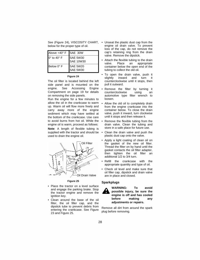
See (Figure 24), VISCOSITY CHART,below for the proper type of oil.
Figure 24
The oil filter is located behind the leftside panel and is mounted on theengine. See Accessing EngineCompartment on page 19 for detailson removing the side panels.Run the engine for a few minutes toallow the oil in the crankcase to warmup. Warm oil will flow more freely andcarry away more of the enginesediment which may have settled atthe bottom of the crankcase. Use careto avoid burns from hot oil. While theengine oil is warm, proceed as follows:Note: A length of flexible tubing issupplied with the tractor and should beused to drain the engine oil.
Figure 25
• Place the tractor on a level surfaceand engage the parking brake. Stopthe tractor engine and remove theignition key.
• Clean around the base of the oilfilter, the oil filler cap, and thedipstick tube to prevent debris fromentering the crankcase. See Figure23 and Figure 25.
• Unseat the plastic dust cap from theengine oil drain valve. To preventloss of the cap, do not remove thecap’s retaining ring from the drainvalve. Remove the dipstick.
• Attach the flexible tubing to the drainvalve. Place an appropriatecontainer below the open end of thetubing to collect the old oil.
• To open the drain valve, push itslightly inward and turn itcounterclockwise until it stops, thenpull it outward.
• Remove the filter by turning itcounterclockwise using anautomotive type filter wrench toloosen.
• Allow the old oil to completely drainfrom the engine crankcase into thecontainer below. To close the drainvalve, push it inward, turn clockwiseuntil it stops and then release it.
• Remove the flexible tubing from thedrain valve. Clean the tubing andstore in a safe place for future use.
• Clean the drain valve and push theplastic dust cap onto the valve.
• Apply a light coating of clean oil onthe gasket of the new oil filter.Thread the filter on by hand until thegasket contacts the oil filter adapter,then tighten the oil filter anadditional 1/2 to 3/4 turn.
• Refill the crankcase with theappropriate quantity and type of oil.
• Check oil level and make sure thatoil filler cap, dipstick and drain valveare in place and closed.
Sparkplugs
WARNING: To avoidpossible injury, be sure theengine is off and has cooledbefore making anyadjustments or repairs.
Remove all dirt from around the sparkplug before removing.
Above +40° F SAE 30W
0° to 40° F SAE 5W30SAE 10W30
Below 0° F SAE 5W20SAE 5W30
Oil Filter
Oil Drain Valve

29
To remove the spark plugs, alwaysuse a spark plug wrench. Check thegap after every 100 hours of operation.Replace a defective plug with a newplug. Set the spark plug gap at .030inch. Tighten the plug to 10-15 ft-lbs.See your authorized dealer for thecorrect replacement plug.
Changing Fuel Filter
WARNING: Do not replacethe fuel filter when engine ishot.
The engine is equipped with an in-linefuel filter. Visually inspect the filterperiodically for a build-up of residueinside the filter body, and for a dirtyelement which can be indicated bydiscoloration. Replace the fuel filterwhen dirty.
Changing Air Cleaner
Figure 26
Check the air cleaner daily or beforestarting the engine. Check for loose ordamaged components and check thecondition of the filter element. Remove
any buildup of dirt and debris in the aircleaner housing.See Figure 26 for assembly of theAircleaner elements.
WARNING: Operating theengine with loose or dam-aged air cleaner componentswill allow unfiltered air intothe carburetor, causingextensive wear and eventualfailure of the engine.
Servicing The Precleaner
Wash and re-oil the foam precleanermore often under extremely dusty ordirty conditions. See Figure 26.• Loosen the aircleaner cover clips
and remove the cover.
• Remove the foam precleaner bysliding it up off the paper element.
• Wash the precleaner in warm waterwith detergent. Rinse the precleanerthoroughly until all traces of thedetergent are eliminated. Squeezeout (do not wring) excess water in adry cloth. Allow the precleaner to airdry.
• Saturate the foam precleaner withnew engine oil. Squeeze out allexcess oil in a dry cloth.
• Reinstall the foam precleaner overthe paper element.
• Reinstall the air cleaner cover andreattach the cover clips to both sidesof the air cleaner body.
Servicing The Paper Element
Inspect an replace the paper elementas necessary. See Figure 26.• Loosen the air cleaner cover clips
and remove the cover.
• Loosen and remove the elementcover nut.
• Remove element cover by liftingstraight up.
Air CleanerCover
Element Cover Nut
Element Cover
Foam Precleaner
Paper Element
Air Cleaner Base

30
• Remove the foam precleaner bysliding it up off the paper element.
• Lift out the paper air filter element.
• Do not wash the paper element oruse pressurized air, as this willdamage the element. Replace adirty, bent or damaged element.Handle new elements carefully; donot use if the sealing surfaces arebent or damaged.
• When servicing the air cleaner,check the air cleaner body. Makesure it is secured and not bent or
damaged. Also check the elementcover plate for damage or improperfit. Replace all damaged air cleanercomponents.
• Reinstall the paper element, foamprecleaner, cover plate and elementcover nut. Reinstall the air cleanercover and reattach the cover.
IMPORTANT: Properly cleaned andinstalled air cleaner elementssignificantly contribute to prolongingengine life.

31
SECTION 12: TROUBLE SHOOTING
Possible Cause Possible Remedy
Hard To StartNo fuel in fuel tank or carburetor Fill the tank with fuel. Check the fuel line,
carburetor and fuel filter.
Fuel ine or carburetor clogged Clean the fuel line and carburetor with a commercial carburetor cleaner.
Fuel filter plugged Replace
Water in fuel Drain the fuel tank and carburetor. Use new fuel and dry the sparks plugs.
Choked improperly. Flooded engine Follow the starting instructions.Defective ignition or loose wiring Check the wiring, spark plugs or fuse.Defective battery Check and service. Refer to “BATTERY.”Spark plug dirty or improperly gapped Clean, adjust the gap to .030-inch or replace
the plug.
Engine Operates Irregularly or KnocksEngine incorrectly timed See your authorized dealer.Spark plug dirty; wrong gap or wrong type Clean, reset the gap or replacePoor or weak spark Check the spark plugs and wiring.Carburetor setting incorrect Adjust. Refer to “ADJUSTMENTS.”Poor grade fuel or water in fuel Drain and use a good grade of clean fuel.Engine overheating Refer to “MAINTENANCE.”Engine valves at fault See your authorized dealer.Engine smokes See your authorized dealer.Oil level rises due to fuel in the crankcase See your authorized dealer.Air filter becomes oil and fuel soaked See your authorized dealer.Engine leaks oil See your authorized dealer.Misfiring See your authorized dealer.Other engine problems See your authorized dealer.Excessive oil in air cleaner Be sure that oil dipstick is fully seated, oil fill
cap is tight, and all excess oil is squeezed out of the pre-cleaner.
PTO Clutch Will Not EngageReverse pedal is partially depressed Depress brake pedal.Vacuum actuator not energized Check PTO switch and connections, check
for worn or broken wiring.
Vacuum leak Check vacuum lines.
Lack of PowerAir cleaner clogged Service the air cleaner element. Refer to
“MAINTENANCE.”
Engine overload Reduce the load.
Engine overheated Make sure the air intake screen, shrouding, engine fins, side panels, dash intake screen and grille are free of accumulated dirt and debris. Refer to “MAINTENANCE.”

32
SECTION 13: OPTIONAL EQUIPMENTWhen you purchased your tractor, you probably had it completely equipped foryour particular needs at that time. However, later you may wish to obtainoptional equipment or accessories. These items and other allied equipment canbe purchased from, and installed by, your authorized Cub Cadet dealer.
This tractor can be used for many different types of work, and because it iscalled on to operate under many different conditions, a variety or equipment isavailable to adapt it to the requirements of the user. Refer to the optionalequipment chart below for a list of products available at the time of printing.
(1) Requires front hitch system 190-343-100.(2) Requires front hitch system 190-343-100. Can use optional Mechanical
Angling Kit 190-171-100 or Hydraulic Angling Kit 190-288-100.
Fuel tank air vent clogged Remove obstruction from the vent in the fuel tank cap.
Air leakage between carburetor and engine Remove air cleaner. Tighten the carburetor and manifold mounting hardware. Replace any damaged parts as indicated in “MAIN-TENANCE.”
Incorrect timing or faulty ignition See your authorized dealer.
Brake dragging Adjust the brakes. Refer to “ADJUST-MENTS.”
Insufficient cooling air — dirt or debris clog-ging the: air intake screen • shrouds • cool-ing fins • side panels • dash intake screen • or grille
Keep the air intake area, side panels, grille, dash intake screen and cooling fins clean. Refer to “MAINTENANCE.”
Oil level incorrect Engine oil level must not be over the “FULL” mark of below the “ADD” mark on dipstick. Refer to “MAINTENANCE.”
Description Model Number
Mechanical Angling Kit (1) 190-171-100
Hydraulic Angling Kit (1) 190-288-100
48” Mower Deck 190-289-100
54” Mower Deck 190-290-100
Front Hitch System 190-343-100
Grass Collection System 190-345-100
54 Inch Blade (2) 190-352-100
Snow Thrower (1) 190-353-100
3 Point Hitch 190-365-100
Possible Cause Possible Remedy
33
SECTION 14: SPECIFICATIONSEngine
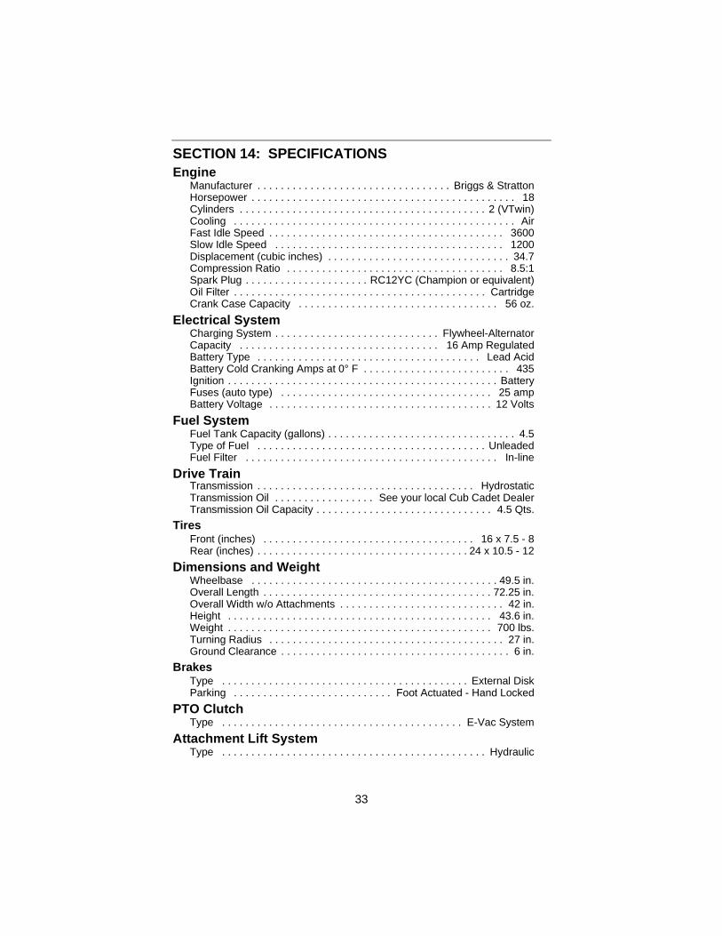
Manufacturer . . . . . . . . . . . . . . . . . . . . . . . . . . . . . . . . . Briggs & StrattonHorsepower . . . . . . . . . . . . . . . . . . . . . . . . . . . . . . . . . . . . . . . . . . . . . 18Cylinders . . . . . . . . . . . . . . . . . . . . . . . . . . . . . . . . . . . . . . . . . . 2 (VTwin)Cooling . . . . . . . . . . . . . . . . . . . . . . . . . . . . . . . . . . . . . . . . . . . . . . . . AirFast Idle Speed . . . . . . . . . . . . . . . . . . . . . . . . . . . . . . . . . . . . . . . . 3600Slow Idle Speed . . . . . . . . . . . . . . . . . . . . . . . . . . . . . . . . . . . . . . . 1200Displacement (cubic inches) . . . . . . . . . . . . . . . . . . . . . . . . . . . . . . . 34.7Compression Ratio . . . . . . . . . . . . . . . . . . . . . . . . . . . . . . . . . . . . . 8.5:1Spark Plug . . . . . . . . . . . . . . . . . . . . . RC12YC (Champion or equivalent)Oil Filter . . . . . . . . . . . . . . . . . . . . . . . . . . . . . . . . . . . . . . . . . . . CartridgeCrank Case Capacity . . . . . . . . . . . . . . . . . . . . . . . . . . . . . . . . . . 56 oz.
Electrical SystemCharging System . . . . . . . . . . . . . . . . . . . . . . . . . . . . Flywheel-AlternatorCapacity . . . . . . . . . . . . . . . . . . . . . . . . . . . . . . . . . . 16 Amp RegulatedBattery Type . . . . . . . . . . . . . . . . . . . . . . . . . . . . . . . . . . . . . . Lead AcidBattery Cold Cranking Amps at 0° F . . . . . . . . . . . . . . . . . . . . . . . . . 435Ignition . . . . . . . . . . . . . . . . . . . . . . . . . . . . . . . . . . . . . . . . . . . . . . BatteryFuses (auto type) . . . . . . . . . . . . . . . . . . . . . . . . . . . . . . . . . . . . 25 ampBattery Voltage . . . . . . . . . . . . . . . . . . . . . . . . . . . . . . . . . . . . . . 12 Volts
Fuel SystemFuel Tank Capacity (gallons) . . . . . . . . . . . . . . . . . . . . . . . . . . . . . . . . 4.5Type of Fuel . . . . . . . . . . . . . . . . . . . . . . . . . . . . . . . . . . . . . . . UnleadedFuel Filter . . . . . . . . . . . . . . . . . . . . . . . . . . . . . . . . . . . . . . . . . . . In-line
Drive TrainTransmission . . . . . . . . . . . . . . . . . . . . . . . . . . . . . . . . . . . . . HydrostaticTransmission Oil . . . . . . . . . . . . . . . . . See your local Cub Cadet DealerTransmission Oil Capacity . . . . . . . . . . . . . . . . . . . . . . . . . . . . . . 4.5 Qts.
TiresFront (inches) . . . . . . . . . . . . . . . . . . . . . . . . . . . . . . . . . . . . 16 x 7.5 - 8Rear (inches) . . . . . . . . . . . . . . . . . . . . . . . . . . . . . . . . . . . . 24 x 10.5 - 12
Dimensions and WeightWheelbase . . . . . . . . . . . . . . . . . . . . . . . . . . . . . . . . . . . . . . . . . . 49.5 in.Overall Length . . . . . . . . . . . . . . . . . . . . . . . . . . . . . . . . . . . . . . . 72.25 in.Overall Width w/o Attachments . . . . . . . . . . . . . . . . . . . . . . . . . . . . 42 in.Height . . . . . . . . . . . . . . . . . . . . . . . . . . . . . . . . . . . . . . . . . . . . . 43.6 in.Weight . . . . . . . . . . . . . . . . . . . . . . . . . . . . . . . . . . . . . . . . . . . . . 700 lbs.Turning Radius . . . . . . . . . . . . . . . . . . . . . . . . . . . . . . . . . . . . . . . . 27 in.Ground Clearance . . . . . . . . . . . . . . . . . . . . . . . . . . . . . . . . . . . . . . . 6 in.
BrakesType . . . . . . . . . . . . . . . . . . . . . . . . . . . . . . . . . . . . . . . . . . External DiskParking . . . . . . . . . . . . . . . . . . . . . . . . . . . Foot Actuated - Hand Locked
PTO ClutchType . . . . . . . . . . . . . . . . . . . . . . . . . . . . . . . . . . . . . . . . . E-Vac System
Attachment Lift System Type . . . . . . . . . . . . . . . . . . . . . . . . . . . . . . . . . . . . . . . . . . . . . Hydraulic
34
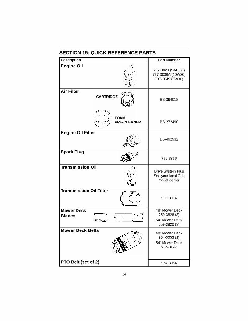
SECTION 15: QUICK REFERENCE PARTSDescription Part Number
Engine Oil 737-3029 (SAE 30)737-3030A (10W30)
737-3049 (5W30)
Air Filter
BS-394018
BS-272490
Engine Oil Filter BS-492932
Spark Plug 759-3336
Transmission Oil Drive System PlusSee your local Cub
Cadet dealer
Transmission Oil Filter
923-3014
Mower Deck Blades
48” Mower Deck759-3826 (3)
54” Mower Deck759-3820 (3)
Mower Deck Belts
PTO Belt (set of 2)
48” Mower Deck954-3053 (1)
54” Mower Deck954-0197
954-3084
CARTRIDGE
FOAMPRE-CLEANER

35
SECTION 16: SLOPE GAUGEWARNING: Do not mow on inclines with a slope in excess of15 degrees (a rise of approximately 2-1/2 feet every 10 feet). A ridingmower could overturn and cause serious injury. If operating a walk-behind mower on such a slope, it is extremely difficult to maintainyour footing and you could slip, resulting in serious injury.
• Operate RIDING mowers up and down slopes, never across the face of slopes.
• Operate WALK-BEHIND mowers across the face of slopes, never up and downslopes.
US
E T
HIS
PA
GE
AS
A G
UID
E T
O D
ET
ER
MIN
E S
LO
PE
S W
HE
RE
YO
U M
AY
NO
T O
PE
RA
TE
SA
FE
LY
.
SIG
HT
AN
D H
OLD
TH
IS L
EV
EL
WIT
H A
VE
RT
ICA
L T
RE
E
A P
OW
ER
PO
LE
A C
OR
NE
R O
F A
BU
ILD
ING
OR
A F
EN
CE
PO
ST
FO
LD O
N D
OT
TE
D L
INE
, RE
PR
ES
EN
TIN
G A
15°
SLO
PE
15°

LIMITED WARRANTY
TWO-YEAR RESIDENTIALONE-YEAR COMMERCIAL
Proper maintenance of your Cub Cadet equipment is the owner’s responsibility.Follow the instructions in your operator’s manual for correct lubricants andmaintenance schedule. Your Cub Cadet dealer carries a complete line of qualitylubricants and filters for your equipment’s engine, transmission, chassis andattachments.
Riding mowers, lawn tractors, garden tractors, Cub Cadet attachments and home maintenance products
This limited warranty for residential users, covers any defect in materials orworkmanship in your Cub Cadet equipment for two years from the date ofpurchase for the first user purchaser. We will replace or repair any part or partswithout charge through your authorized Cub Cadet dealer.Batteries have a one-year prorated limited warranty with 100% replacementduring the first three months.V-belts for either the traction drive or any attachments are covered for one yearonly.Cub Cadet equipment used commercially is warranted for one year only.(Commercial use is defined as either having hired operators or used for incomeproducing purposes).
Items not coveredThe warranty does not cover routine maintenance items such as lubricants,filters (oil, fuel, air and hydraulic), cleaning, tune-ups, brake and/or clutchinspection, adjustments made as part of normal maintenance, blade sharpening,set-up, abuse, accidents and normal wear. It does not cover incidental costssuch as transporting your equipment to and from the dealer, telephone chargesor renting a product temporarily to replace a warranted product.There is no other express warranty.
How to obtain serviceContact your authorized Cub Cadet servicing dealer who sold you your CubCadet equipment. If this dealer is not available, see the Consumer YellowPages under “lawn mowers” for the name of a dealer near you.If you need further assistance in finding an authorized Cub Cadet servicingdealer, contact:
Cub Cadet CorporationPost Office Box 368023Cleveland, Ohio 44136
How does state law apply?This limited warranty gives you specific legal rights, and you may also have otherrights which vary from state to state.