Embed Size (px)
Citation preview

MONITORING OF THE LAUNCHED GIRDER BRIDGE
OVER THE IOWA RIVER ON US 20
Sponsored bythe Iowa Department of Transportation
Office of Bridges and Structures
Final Report March 2004
CTRE Project 01-108
Bridge Engineering Center

The opinions, findings, and conclusions expressed in this publication are those of the authors andnot necessarily those of the Iowa Department of Transportation.
CTRE’s mission is to develop and implement innovative methods, materials, and technologiesfor improving transportation efficiency, safety, and reliability while improving the learningenvironment of students, faculty, and staff in transportation-related fields.

Technical Report Documentation Page
1. Report No. 2. Government Accession No. 3. Recipient’s Catalog No. CTRE Project 01-108
4. Title and Subtitle 5. Report Date March 2004 6. Performing Organization Code
Monitoring of the Launched Girder Bridge over the Iowa River on US 20
7. Author(s) 8. Performing Organization Report No. T.J. Wipf, B.M. Phares, R.A. Abendroth, D.L. Wood, B. Chang, and S. Abraham 9. Performing Organization Name and Address 10. Work Unit No. (TRAIS)
11. Contract or Grant No.
Center for Transportation Research and Education Iowa State University 2901 South Loop Drive, Suite 3100 Ames, IA 50010-8634
12. Sponsoring Organization Name and Address 13. Type of Report and Period Covered Final Report 14. Sponsoring Agency Code
Iowa Department of Transportation 800 Lincoln Way Ames, IA 50010 15. Supplementary Notes This report is available in color at www.ctre.iastate.edu. 16. Abstract
The objective of the study presented in this report was to document the launch of the Iowa River Bridge and to monitor and evaluate the structural performance of the bridge superstructure and substructure during the launch.
The Iowa Department of Transportation used an incremental launching method, which is relatively unique for steel I-girder bridges, to construct the Iowa River Bridge over an environmentally sensitive river valley in central Iowa. The bridge was designed as two separate roadways consisting of four steel plate girders each that are approximately 11 ft deep and span approximately 301 ft each over five spans. The concrete bridge deck was not placed until after both roadways had been launched. One of the most significant monitoring and evaluation observations related to the superstructure was that the bottom flange (and associated web region) was subjected to extremely large stresses during the crossing of launch rollers. Regarding the substructure performance, the column stresses did not exceed reasonable design limits during the daylong launches. The scope of the study did not allow adequate quantification of the measured applied launch forces at the piers. Future proposed research should provide an opportunity to address this. The overall experimental performance of the bridge during the launch was compared with the predicted design performance. In general, the substructure design, girder contact stress, and total launching force assumptions correlated well with the experimental results. The design assumptions for total axial force in crossframe members, on the other hand, differed from the experimental results by as much as 300%. 17. Key Words 18. Distribution Statement bridge construction—launched girder bridge No restrictions. 19. Security Classification (of this report)
20. Security Classification (of this page)
21. No. of Pages 22. Price
Unclassified. Unclassified. 94 NA

MONITORING OF THE LAUNCHED GIRDER BRIDGE OVER THE IOWA RIVER ON US 20
CTRE Project 01-108
Principal Investigator
T.J. Wipf Director, Bridge Engineering Center
Co-Principal Investigator
B.M. Phares Associate Director, Center for Transportation Research and Education
Associate Director, Bridge Engineering Center
Investigators R.A. Abendroth
Associate Professor, Department of Civil, Construction, and Environmental Engineering
D.L. Wood Manager, Engineering Laboratories, Department of Civil, Construction, and Environmental Engineering
Graduate Research Assistants
B. Chang, S. Abraham Student, Center for Transportation Research and Education
Authors
T.J. Wipf, B.M. Phares, R.A. Abendroth, D.L. Wood, B. Chang, and S. Abraham
Preparation of this report was financed in part through funds provided by the Iowa Department of Transportation
through its research management agreement with the Center for Transportation Research and Education.
Center for Transportation Research and Education Iowa State University
2901 South Loop Drive, Suite 3100 Ames, IA 50010-8632 Phone: 515-294-8103
Fax: 515-294-0467 www.ctre.iastate.edu
Final Report • March 2004

iii
TABLE OF CONTENTS
EXECUTIVE SUMMARY.......................................................................................................................... X
1. INTRODUCTION .................................................................................................................................... 1 1.1. Background.............................................................................................................................. 1 1.2. Bridge Description ................................................................................................................... 1 1.3. Report Summary ...................................................................................................................... 3
2. LITERATURE REVIEW ......................................................................................................................... 5 2.1. History and Background .......................................................................................................... 5 2.2. Monitoring of the Parana River Bridge Launching ................................................................. 5 2.3. Serviceability Limit State for Steel Girders during Launching ............................................... 6 2.4. Local Launch Stresses.............................................................................................................. 6
3. LAUNCHING CONCEPTS ..................................................................................................................... 7 3.1. Launching Pit ........................................................................................................................... 7 3.2. Rollers...................................................................................................................................... 7 3.3. Launching Nose ....................................................................................................................... 7 3.4. Launching Tail ....................................................................................................................... 11 3.5. Girder Splice Modifications................................................................................................... 11 3.6. Hydraulic Equipment ............................................................................................................. 13 3.7. Permanent Bridge Bearings ................................................................................................... 15
4. MONITORING PROGRAM .................................................................................................................. 17 4.1. Introduction............................................................................................................................ 17 4.2. Instrumentation of Westbound Roadway............................................................................... 17
4.2.1. Launch WB1.......................................................................................................... 17 4.2.2. Launch WB3.......................................................................................................... 17 4.2.3. Launch WB4.......................................................................................................... 22 4.2.4. Launch WB5.......................................................................................................... 22
4.3. Instrumentation of Eastbound Roadway................................................................................ 24 4.3.1. Launch EB3 ........................................................................................................... 24 4.3.2. Launch EB4 ........................................................................................................... 24
4.4. Data Collection Procedures.................................................................................................... 27 4.5. Steel Superstructure Position during Launch Events............................................................. 27
5. INSTRUMENTATION RESULTS ........................................................................................................ 38 5.1. Introduction............................................................................................................................ 38 5.2. Substructure Behavior............................................................................................................ 38
5.2.1. Pier 2 and Pier 3 column strain behavior during EB3, EB4, WB3 and WB4 Launches ........................................................................................................................... 40 5.2.2. Column tilt and deflection behavior during the WB3 Launch............................... 50
5.3. Jacking Forces........................................................................................................................ 54

iv
5.4. Girder Behavior ..................................................................................................................... 56 5.5. Crossframe Behavior ............................................................................................................. 68
6. DISCUSSION OF STUDY RESULTS .................................................................................................. 78 6.1. Substructure Behavior............................................................................................................ 78 6.2. Jacking Forces........................................................................................................................ 79 6.3. Girder Behavior ..................................................................................................................... 80 6.4. Cross-frame Behavior ............................................................................................................ 81
7. RECOMMENDATIONS FOR FUTURE LAUNCHED BRIDGES...................................................... 83 7.1. Summary ................................................................................................................................ 83 7.2. Recommendations.................................................................................................................. 83
8. REFERENCES ....................................................................................................................................... 85

v
LIST OF FIGURES
Figure 1.1. Iowa River Bridge girder system overview. ............................................................................... 2 Figure 3.2. Launching pit with partial girder assembly in place................................................................... 9 Figure 3.3. Horizontal and vertical launching rollers. .................................................................................. 9 Figure 3.4. Guide roller equipped with 50-ton hydraulic jack.................................................................... 10 Figure 3.5. Launching nose cantilevered beyond Pier 4 (Eastbound bridge shown). ................................. 10 Figure 3.6. Tapered launching tail attached to the girder system. .............................................................. 11 Figure 3.7. Vertical roller positioned between bottom flange splice plate bolts......................................... 12 Figure 3.8. Tapered ramp plate at a bolted girder splice............................................................................. 12 Figure 3.9. Gantry assembly supporting the hydraulic cylinder. ................................................................ 13 Figure 3.10. Complete jacking system........................................................................................................ 14 Figure 3.11. Rear of launching tail showing transverse tugger beam. ........................................................ 14 Figure 3.12. Spreader beams located between the tugger beam and the tail section. ................................. 15 Figure 3.13. Piers 2-5 permanent fixed pot-bearing details. ....................................................................... 16 Figure 4.1. Instrumentation of cross-frame members – Launch WB1........................................................ 18 Figure 4.2. Instrumentation of Girders C and D – Launch WB1................................................................ 19 Figure 4.3. Instrumentation of Pier 3 – Launch WB3................................................................................. 20 Figure 4.4. Instrumentation of rollers B and C – Launch WB3 and WB4.................................................. 21 Figure 4.5. Typical strain transducer configuration on roller assembly. .................................................... 21 Figure 4.7. Instrumentation of Pier 2 – Launch WB4................................................................................. 23 Figure 4.8. Instrumentation of cross-frame members – Launch WB5........................................................ 24 Figure 4.9. Instrumentation of Pier 3 – Launch EB3. ................................................................................. 25 Figure 4.10. Instrumentation of Pier 2 – Launch EB4. ............................................................................... 26 Figure 5.1. Representative sample of individual segmental concrete pier strain data for the EB3 Launch
prior to temperature compensation and data stitching. .................................................................. 39 Figure 5.2. Daylong concrete column strain records at Pier 2 and Pier 3 during EB3, EB4, WB3, and
WB4 Launches............................................................................................................................... 41 Figure 5.2. Continued. ................................................................................................................................ 42 Figure 5.3. Comparison of concrete column strain data for the EB3 and WB3 Launches. ........................ 43 Figure 5.4. Comparison of concrete column strain data for the EB4 and WB4 Launches. ........................ 43 Figure 5.5. Comparison of Pier 2 and Pier 3 concrete column strain data during the WB3 and WB4
Launches. ....................................................................................................................................... 44 Figure 5.6. Comparison of NW and NE concrete column strain data during the WB4 Launch. ................ 44 Figure 5.7. Comparison of NW and SW concrete column strain data during the WB4 Launch. ............... 45 Figure 5.8. Partial strain data for the SW and NW concrete column faces for the WB3 Launch............... 46 Figure 5.9. Concrete column strain during the passage of a bolted splice during the WB3 Launch. ......... 47 Figure 5.10. Concrete column strain during the passage of a welded flange transition during the WB4
Launch. .......................................................................................................................................... 47 Figure 5.11. Strain data at the NW and SW concrete column faces during latter stages of the WB4
Launch. .......................................................................................................................................... 48 Figure 5.12. Strain data at the NW and SW concrete column faces illustrating possible slip of pier near
end of the WB4 Launch. ................................................................................................................ 49 Figure 5.13. Strain data at the NW and SW concrete column faces illustrating possible slip of pier near
the end of the EB3 Launch............................................................................................................. 50 Figure 5.14. Strain data at the NW and SW concrete column faces during the EB4 Launch illustrating a
significant torsion event................................................................................................................. 51 Figure 5.15. Longitudinal tilt at the top of Pier 3 during the WB3 Launch................................................ 51 Figure 5.16. Longitudinal tilt at the bottom of Pier 3 during the WB3 Launch.......................................... 52 Figure 5.17. Longitudinal deflection at the bottom of Pier 3 during the WB3 Launch. ............................. 53 Figure 5.18. Strain data for the WB3 Launch at the NW and SW concrete column faces compared with

vi
longitudinal deflections of the Pier 3 foundation at the NW and SW locations. ........................... 53 Figure 5.19. Comparison of tilt at the top of the North and South columns of Pier 3 with strain at the NW
and SW concrete column faces during the WB3 Launch. ............................................................. 54 Figure 5.20. Jacking forces measured during the WB1 Launch. ................................................................ 55 Figure 5.21. Jacking forces measured during the WB3 Launch. ................................................................ 56 Figure 5.22. Steel girder, bottom flange, longitudinal strain during the WB1 Launch. ............................. 57 Figure 5.23. Steel girder longitudinal strain profile for Girder C during the WB1 Launch. ...................... 59 Figure 5.24. Steel girder longitudinal strain profile for Girder D during the WB1 Launch. ...................... 60 Figure 5.25. Longitudinal strain at the upper surface of the Girder C bottom flange (steel) during the WB3
Launch. .......................................................................................................................................... 61 Figure 5.26. Longitudinal strain at the upper surface of the Girder D bottom flange (steel) during the WB3
Launch. .......................................................................................................................................... 62 Figure 5.27. Upper surface of bottom flange (steel) longitudinal strain profile during the WB3 Launch.. 63 Figure 5.28. Longitudinal strain at the bottom surface of the Girder C bottom flange (steel) during the
WB3 Launch. ................................................................................................................................. 64 Figure 5.29. Longitudinal strain at the bottom surface of the Girder D bottom flange (steel) during the
WB3 Launch .................................................................................................................................. 65 Figure 5.30. Lower surface of bottom flange (steel) longitudinal strain profile for Girder C during the
WB3 Launch. ................................................................................................................................. 66 Figure 5.31. Lower surface of bottom flange (steel) longitudinal strain profile for Girder D during the
WB3 Launch. ................................................................................................................................. 67 Figure 5.32. Vertical strain in the lower portion of the Girder C steel web plate during the WB3 Launch.69 Figure 5.33. Vertical strain in the lower portion of the Girder D steel web plate during the WB3 Launch.70 Figure 5.34. Vertical strain profile in lower part of steel girder web plate during the WB3 Launch. ........ 71 Figure 5.35. Typical steel cross-frame behavior at Section A of panel 3 during the WB1 Launch............ 72 Figure 5.36. Typical steel cross-frame behavior at Section A during the WB5 Launch. ........................... 74

vii
LIST OF TABLES
Table 5.1. Weather data for the EB3, EB4, WB3 and WB4 Launches....................................................... 38 Table 5.2. Additional jacking resistance conditions during launch WB1................................................... 55 Table 5.3. Likely cause of launching force spikes during the WB3 Launch. ............................................. 55 Table 5.4. Launch WB1 cross-frame member behavior. ............................................................................ 76 Table 5.5. Launch WB5 cross-frame member behavior. ............................................................................ 77

viii
LIST OF NOTATIONS
BN Tilt transducer at the bottom of the Northernmost pier column BS Tilt transducer at the bottom of the Southernmost pier column CBF Middle strain gage, Girder C, bottom surface of bottom flange CNBW Bottom strain gage, Girder C, North side of web CNIF Innermost strain gage, Girder C, top surface of North side of bottom flange CNMW Middle strain gage, Girder C, North side of web CNOBF Outermost strain gage, Girder C, bottom surface of North side of bottom flange CNOF Outermost strain gage, Girder C, top surface of North side of bottom flange CNTW Topmost strain gage, Girder C, North side of web CSBW Bottom strain gage, Girder C, South side of web CSIF Innermost strain gage, Girder C, top surface of South side of bottom flange CSMW Middle strain gage, Girder C, South side of web CSOBF Outermost strain gage, Girder C, bottom surface of South side of bottom flange CSOF Outmost strain gage, Girder C, top surface of South side of bottom flange CSTW Topmost strain gage, Girder C, South side of web CBF Middle strain gage, Girder C, bottom surface of bottom flange DNBW Bottom strain gage, Girder D, North side of web DNIF Innermost strain gage, Girder D, top surface of North side of bottom flange DNMW Middle strain gage, Girder D, North side of web DNOBF Outermost strain gage, Girder D, bottom surface of North side of bottom flange DNOF Outermost strain gage, Girder D, top surface of North side of bottom flange DNTW Topmost strain gage, Girder D, North side of web DOT Department of Transportation DR Down ramp DSBW Bottom strain gage, Girder D, South side of web DSIF Innermost strain gage, Girder D, top surface of South side of bottom flange DSMW Middle strain gage, Girder D, South side of web DSOBF Outermost strain gage, Girder D, bottom surface of South side of bottom flange DSOF Outmost strain gage, Girder D, top surface of South side of bottom flange DSTW Topmost strain gage, Girder D, South side of web EB3 Eastbound roadway, Launch #3 EB4 Eastbound roadway, Launch #4 FHWA Federal Highway Administration FS Field splice IRB Iowa River Bridge GCBF1 Northernmost Girder C, bottom flange strain gage GCBF2 Northernmost Girder C, bottom flange strain gage GCTF1 Northernmost Girder C, top flange strain gage GCTF2 Southernmost Girder C, top flange strain gage GCW1 Northernmost Girder C, web strain gage GCW2 Southernmost Girder C, web strain gage GDBF1 Northernmost Girder D, bottom flange strain gage GDBF2 Northernmost Girder D, bottom flange strain gage GDTF1 Northernmost Girder D, top flange strain gage GDTF2 Southernmost Girder D, top flange strain gage GDW1 Northernmost Girder D, web strain gage GDW2 Southernmost Girder D, web strain gage Girder A Westbound roadway, Northernmost exterior girder

ix
Girder B Westbound roadway, Northernmost interior girder Girder C Westbound roadway, Southernmost interior girder Girder D Westbound roadway, Southernmost exterior girder Girder E Eastbound roadway, Northernmost exterior girder Girder F Eastbound roadway, Northernmost interior girder Girder G Eastbound roadway, Southernmost interior girder Girder H Eastbound roadway, Southernmost exterior girder IP Distance from Pier 1 bearing stiffener NCHRP National Cooperative Highway Research Program NE48 Pier gage, 48 in. below reference plane at Northeast face of pier NE90 Pier gage, 90 in. below reference plane at Northeast face of pier oriented vertically NE90T Pier gage, 90 in. below reference plane at Northeast face of pier oriented at 45 degrees NN Deflection gage oriented to measure Northerly deflection of Northernmost pier column NTIS National Transportation Information Service NW Deflection gage oriented to measure Westerly deflection of Northernmost pier column NW48 Pier strain gage, 48 in. below reference plane at Northwest face of pier NW90 Pier strain gage, 90 in. below reference plane at Northwest face of pier oriented vertically NW90T Pier strain gage, 90 in. below reference plane at Northwest face of pier oriented at 45
degrees SE48 Pier strain gage, 48 in. below reference plane at Southeast face of pier SE90 Pier strain gage, 90 in. below reference plane at Southeast face of pier oriented vertically SE90T Pier strain gage, 90 in. below reference plane at Southeast face of pier oriented at 45
degrees SS Deflection gage oriented to measure Southerly deflection of Southernmost pier column SW Deflection gage oriented to measure Westerly deflection of Southernmost pier column SW48 Pier strain gage, 48 in. below reference plane at Southwest face of pier SW90 Pier strain gage, 90 in. below reference plane at Southwest face of pier oriented vertically SW90T Pier strain gage, 90 in. below reference plane at Southwest face of pier oriented at 45
degrees TN Tilt transducer at the top of the Northernmost pier column TNE Pier temperature compensation gage at Northeast face of pier TNW Pier temperature compensation gage at Northwest face of pier TRB Transportation Research Board TS Tilt transducer at the top of the Southernmost pier column TSE Pier temperature compensation gage at Southeast face of pier TSW Pier temperature compensation gage at Southwest face of pier WB1 Westbound roadway, Launch #1 WB2 Westbound roadway, Launch #2 WB4 Westbound roadway, Launch #4 WB5 Westbound roadway, Launch #5 UR Up ramp

x
EXECUTIVE SUMMARY
The objective of the study presented in this report was to document the launch of the Iowa River Bridge and to monitor and evaluate the structural performance of the steel bridge superstructure and reinforced concrete substructure during the launch. The report contains information related to the launching elements used during the bridge construction as well as documentation of the bridge instrumentation and monitoring procedures. Experimental results from the bridge monitoring are included along with comparisons between the design assumptions and subsequent experimental results. The Iowa Department of Transportation used an incremental launching method, which is relatively unique for steel I-girder bridges, to construct the Iowa River Bridge over an environmentally sensitive river valley in central Iowa. The bridge was designed as two separate roadways consisting of four steel plate girders each that are approximately 11 ft deep and span approximately 301 ft each over five spans. The concrete bridge deck was not placed until after both roadways had been launched.
The launch system included a launch pit that could accommodate the construction, at grade, of an approximate superstructure length of 500 ft prior to launching. During the launch, the four roadway girders were supported at the bridge piers (and also on temporary bents in the launch pit) by four temporary bearing rollers. A temporary launch nose consisting of two tapered girders (attached to the two interior bridge girders) was located at the leading edge of the launched roadway to facilitate touch down at the piers and to lift the superstructure as it crossed the rollers. A hydraulic jacking system was used to develop the force needed to “push” the steel superstructure between piers during the launch. The two 250-ton capacity hydraulic cylinder assemblies were connected to two high-strength post-tensioning bars that were connected to a tail assembly at the rear of the launched superstructure.
The launched bridge substructure and superstructure was monitored to obtain strain, deflection, tilt, and load data for six individual, full-span launches (EB3, EB4, WB1, WB3, WB4 and WB5 Launches – a different set of monitoring objectives was associated with each launch). The substructure assessment focused on both global and local pier column behavior. The monitoring of the steel superstructure included assessment of girder flexural behavior, girder contact stress at the temporary bridge roller bearings, and cross-frame force distribution and magnitudes. The launching force applied to the superstructure was also monitored during several launches.
The study results were presented in four categories associated with: substructure behavior, jacking forces, girder behavior, and cross-frame behavior. The most significant results associated with each category are discussed in the subsequent paragraphs. The experimental results are discussed in their entirety first and a discussion of the design assumptions compared with experimental results follows.
Regarding the substructure performance, the taller of the two monitored piers, Pier 3, sustained significantly smaller column stress (combined axial and bending) from the daylong launch forces than did Pier 2. In addition, the Pier 3 response during the launch of both the eastbound and the westbound roadways were very similar, as was the Pier 2 response during these two roadway launches. The largest column stress for a daylong launch was approximately 600 psi. It’s noted that the foundation system for Pier 3 was a drilled shaft and Pier 2 had a driven pile spread footing foundation system. Also, there were observed residual or “locked in” stresses in the pier columns at the end of the daylong launches. Similarly, residual deflections near the pier foundation were measured at the end of the WB3 Launch.
The jacking force behavior identified during the WB1 and WB3 Launches was quantified by the instrumentation of post-tensioning rods on both sides of launched roadway. Typically, the measured forces in the rods were unequal, but responded in a similar manner. The largest measured applied force was during the WB3 Launch and was approximately 210 kips in the south rod and 175 kips in the north rod (total force of approximately 385 kips). It was associated with movement of the superstructure over a launch roller at a bolted splice ramp.
The contact stresses measured on the bottom flange and web of two instrumented girders as they rolled over the temporary supports in the launch pit were extremely large. For the two girders monitored, the maximum bottom flange stresses were approximately 127 ksi and 221 ksi, respectively, based on an uniaxial, elastic stress condition. The corresponding web stresses at the junction of the bottom flange (also based on the assumption of an uniaxial, elastic stress condition) for the same girders were 52 ksi and

xi
59 ksi, respectively. It should be noted that these web stresses were extrapolated from actual measured data near the flange/web junction.
Axial forces were calculated for typical cross-frame members during two separate launches based on the measured strain data. In general, the cross-frame behavior was quite different between the two launches and appears to exhibit relatively complex structural behavior. While the calculated member forces were considered to be relatively large (the largest measured peak strain corresponded to an approximate stress of 33 ksi in one member), the measured strains did not exceed yield values.
The overall experimental performance of the bridge during the launch was correlated with the predicted design performance where pertinent design information was available. For the substructure performance (i.e., the pier column strain behavior), only an indirect correlation was possible, since the pier design was not controlled by launch forces. The design of the piers was based on typical bridge loading specified by AASHTO and the design was then checked for predicted launching forces. These design launching forces were computed to be approximately 57 kips per girder when a ramp splice crossed a pier support. A calculation of the predicted column strain due to these forces (based on an analytical model using similar assumptions as used in the design of the pier) for the EB3 and EB4 Launches resulted in column stresses 182 psi and 200 psi, respectively, for Pier 2 and Pier 3 for the SW column faces at one of the monitored locations. The maximum measured strain at the same column location for the SW face was 260 psi and 210 psi, respectively, for Pier 2 and Pier 3. Based on the experimental strain results, it would appear that the pier columns were not compromised during the launch.
The steel superstructure performance was also compared with predicted design behavior for several different superstructure components. For example, regarding the jacking force for launching the girders, the design indicated that the greatest jacking force would be during the final launch (EB5 or WB5), and the maximum jacking force required was calculated as 652 kips for the four girder system. In contrast, the largest measured jacking force was 385 kips, although this occurred for the WB3 Launch when the total weight of the bridge was less than that for the EB5 or WB5 Launch. A calculation similar to that for the 652 kip design value noted above was made for a steel position of EB3 or WB3. This predicted force was 396 kips, which compares well with the maximum measured jacking force of 385 kips for the WB3 Launch.
The contact stress was another steel superstructure behavior that was evaluated. The established design limit of compressive stress due to contact stresses was conservatively determined to be 201 ksi. This limit is assumed to ensure that no plastic flow of the base metal would occur. Although this stress level could not be verified directly, the largest measured longitudinal stress in the bottom flange in the contact region was 221 ksi – also a very high stress level. It is noted that no evidence of plastic flow was visible on the girder flange locations during inspections that were performed after the bridge construction was completed.
The design of the crossframes was actually based on normal wind load applied to the exterior girders. However, the crossframe design was checked for loads caused by providing a braced condition for the compression flange during launching. These associated crossframe member axial forces were considerably smaller than those forces that were calculated for both the WB1 and WB3 Launches. The maximum WB3 Launch axial forces were approximately 2 to 4 times larger than the design member forces, although it’s noted that the calculated axial forces from the measured strain data are extremely sensitive to strain gage accuracy. Based on the specific results associated with the monitoring portion of this study, several noteworthy recommendations should be considered when considering a launch design of similar bridges. The design of the girders should include an analytical assessment of girder contact stresses in the bottom flange/web junction when designing the temporary rollers at the supports during launching. There are a number of ways to accomplish the goal of satisfying the contact stress design, including use of a larger diameter single bearing roller or a series of smaller diameter bearing rollers. This would distribute the concentrated load over a much larger area of the bottom flange. Additionally, the design of the girder cross-frame members should also include an analytical evaluation of the possible forces due to unequal vertical bearing of the girders at the supports during launching. Recognizing that the multiple girder cross

xii
section (with cross-frames included) is essentially a self stiffened frame structure and possibly subject to warping during construction, the guidance system should be designed to reduce movement off line during launching.

1
1. INTRODUCTION 1.1. Background
“Incremental Launching” is one among the many available erection methods for steel plate girder bridges. Although this method is generally not practiced in the United States, increased awareness of the environmental impacts associated with conventional construction methods may make this a more common construction technique. In the incremental launching method, the superstructure of a bridge is erected on one side of the feature to be crossed and then rolled longitudinally into its final position.
After nearly forty years of study, aimed at minimizing the impact of construction on the Iowa River Greenbelt, the Iowa Department of Transportation (DOT) opted to use the incremental launching method to construct the steel plate girder superstructure of the realigned US Highway 20 bridge over the Iowa River in Hardin County, Iowa. The bridge design team, including the Iowa Department of Transportation Office of Bridges and Structures and HNTB Corporation of Kansas City, MO, recognized that, although bridge construction utilizing launching techniques can be expensive and challenging, it also offers the best solution to the complex situation.
There were a number of specific factors that necessitated the use of this unique construction method for the steel girder Iowa River Bridge (IRB):
• Preservation of three species of threatened freshwater mussels that inhabit the Iowa River. • Minimization of disturbance to bald eagles, which utilize a valley adjacent to the bridge for
winter roosting. • Preservation of the endangered Northern Monkshood plant. • Preservation of prehistoric cultural materials and various archeological components. • Preservation of natural resources like rocks and vegetation for future landscaping. • Maintenance of natural scenic beauty and wildlife habitats near the bridge. • Minimization of chemical pollution of the river.
When this project was initiated, there had been only one other project in the United States found
in the available technical literature that used launching techniques. Given the unique conditions associated with the IRB (e.g., steel girders), the Iowa DOT decided that the bridge should be monitored during launching. The goal of the somewhat limited monitoring program was to monitor for damage occurring during launching and to verify, where possible, design assumptions. This report includes a brief literature review related to launching of bridges, a summary of the launching system employed, a description of the monitoring program, and a summary and analysis of the collected data. 1.2. Bridge Description
The launched portion of the IRB spans over the Iowa River with a total length of 1,510 ft and is supported by six piers. A general plan showing overall dimensions and the naming conventions, as well as a typical mid-span section, are shown in Figure 1.1. Note that the bridge was constructed in metric dimensions. For convenience, this report uses English units only – this conversion may result in slight errors in dimensional measurements.
The IRB consists of two parallel deck superstructures, each containing five equal spans of 301.83 ft. A 60.7-ft pre-stressed concrete jump span was also constructed on each end of the steel unit. The pre-stressed concrete spans are not discussed as part of this report. The I-shaped bridge girders are built-up members fabricated from ASTM A709 Grade 50W steel. The girder webs are 11.33 ft deep with the girder lines spaced at 11.81 ft. The designer selected the section depth not based on strength requirements, but rather to reduce the dead load deflection during launching to a reasonable level. Because any point along the girder length could become a bearing location during launching operations, the constant 0.88 in. web thickness was designed to serve as an unstiffened bearing element for the steel dead load.
In order to make the I-girder superstructure act as much like a torsion ally rigid box girder as possible during launching, a very stiff system of diaphragms and lateral bracing was used. A diaphragm

2
5 @ 301'-10"
Westbound Bridge
Eastbound Bridge
Pier 6
Girder D
Girder BGirder C
Girder A
Girder EGirder FGirder GGirder H
Pier 2Pier 4Pier 5
Launch Direction
Pier 3
N (Project)
3 @11'-10"
3 @11'-10"
Pier 1
(a) Plan view
11'-10" Typ.
(b) Typical superstructure cross-section at mid span
Figure 1.1. Iowa River Bridge girder system overview.
spacing of approximately 23 ft was used for spans 2 thru 5, but was reduced to 11.5 ft in the leading span that would be cantilevered during launching. A system of center bay upper and lower lateral bracing, consisting of WT sections (up to 76 lb/ft) was provided to form the “spine” of the girder system. In the leading two panels of the girder system, additional lateral bracing was provided in the outer girder bays as well.
Although not part of the bridge that was launched, the concrete deck in the completed bridge consists of a 9-in concrete slab with a 1.5-in low-slump concrete wearing surface. A high performance concrete mix was used for the deck to minimize the potential for shrinkage and cracking in the positive moment regions.
The foundations of the bridge are 100 ton steel H-pile foundations driven to rock at Piers 1, 2 and 5 and 100 tons steel H-piles driven to refusal in clay at Pier 6. To minimize the footprint of the pier foundations near the river, Piers 3 and 4 are founded on 8 ft diameter drilled shafts approximately 100 ft deep.
Piers 1 and 6 act as both the end support for the continuous steel girder unit and the simple support for the pre-stressed concrete jump spans. The piers are similar in design to a stub abutment with a 12-ft deep (including the depth of the pre-stressed concrete beams) backwall behind the end of the steel girder unit. Piers 2 through 5 consist of two tapered columns with a continuous capbeam. For general

3
dimensions of Piers 2 through 5, see Figure 1.2. The general steps followed in the incrementally launched erection of the Iowa River Bridge consisted
of the following: • Erect the structural steel for the first 505 ft of the eastbound bridge (including girders,
diaphragms, and upper and lower lateral bracing) on temporary pile bents behind Pier 6 in a launching pit.
• Attach launching nose (leading end) and tail section (trailing end) to the girder train. • Hydraulically jack the girder train longitudinally forward 302 ft from Pier 6 to Pier 5. • Remove tail section and splice additional girder sections to the back end of the girder train. • Reinstall tail section. • Hydraulically jack girder train longitudinally to Pier 4. • Repeat sequence for a total of five spans.
The entire eastbound bridge steel unit was launched first. The temporary pile bents were then
removed and reinstalled 43 ft to the North for use in launching the westbound steel unit. 1.3. Report Summary
The report is divided into eight chapters. A brief literature review related to bridge launching is presented in Chapter 2. A description of the launching procedures including a description and use of equipment is summarized in Chapter 3. Chapter 4 presents the instrumentation utilized to monitor the IRB launching process. Results and analysis of the collected data are presented in Chapter 5. In Chapter 6, a discussion of the experimental results with respect to original design assumptions provided by the bridge designer is given. Chapter 7 presents concluding remarks developed from the field collected data and field observations. Chapter 8 lists references cited in this report.

4
Figu
re 1
.2. G
ener
al d
imen
sion
s of P
iers
2 th
roug
h 5.

5
2. LITERATURE REVIEW
A literature review was conducted to collect available information on bridge launching. Many sources were searched, including resources at the Federal Highway Administration (FHWA), National Technical Information Service (NTIS), Transportation Research Board (TRB), and the National Cooperative Highway Research Program (NCHRP). In addition, several other computerized searches were conducted through the Iowa State University Parks Library.
2.1. History and Background
The incremental launching method has been used for many years in the construction of smaller bridges. In fact, a prefabricated steel bridge was developed for the British Army by Sir Donald Bailey in 1941 and widely used by Allied troops during World War II. The Bailey bridge was designed to be built by launching and was constructed of pieces light enough to be quickly constructed by troops using nothing more than manpower (1).
A significant number of steel bridges have been constructed in Europe using the launching method. Svensson (2) points out that the cantilever moments during launching are six times larger than the final support moments on a continuous structure and that the maximum cantilever reaction is greater than 2 times the regular support reaction after construction. In order to prevent local web crippling under these high loadings, it is necessary to use either heavy duty rollers or, as is in the practice in Germany, a sliding bearing which utilizes a Teflon-coated neoprene pad beneath the steel girder. Svensson presents a series of examples of steel bridges that have been successfully launched including: I-girder systems, box girder systems, and, in a few cases, steel arch spans of up to a 600-ft span.
The first steel bridge to be launched in the United States is believed to be a Kansas City Southern Railroad box girder bridge near Redland, OK in 1970 (3). The nine-span continuous bridge is 2,110 ft long with a main span of 330 ft. This bridge was launched in two trains, one from each side of the river. Closure of the bridge was accomplished at mid-span of the main span.
There are three methods available to reduce the cantilever moments during launching (4). Using a lightweight launching nose is the most common method. However, in order to be effective, the nose must be light and stiff. For longer spans, a launching nose is not as effective as other methods. In these cases, temporary piers can be constructed to reduce the cantilever span by one-half when conditions permit a relatively modest foundation and the pier height is not too great. A third method employs a temporary pylon or “kingpost” which supports the leading end. This system produces a large positive moment when the pylon is at mid-span. The stays on such a pylon can be equipped with jacks to adjust the cable tension during launching.
The incremental launching method was first implemented on the Rio Caroni Bridge in Venezuela (5,6). This bridge was built in 1962-1963 by its originators Will Baur and Dr. Fritz Leonhardt. It was a post-tensioned concrete box girder bridge with a major span of 315 ft. Since that time, approximately 1,000 bridges have been constructed using this method or by combining this method with the balanced cantilever method. The primary reasons for the increasing popularity of this construction method is that many bridges are being constructed across increasingly difficult terrain and there is increased awareness of environmentally sensitive areas.
The commercial availability of Teflon has allowed designers to considerably reduce frictional forces transferred to the piers during launching operations. Considerable research has been done on the launching forces applied to the substructure, and Rosignolli presents a discussion of this along with various methods for applying a launching force to the girder system (7).
It is believed that, to date, about 1000 incrementally launched bridges have been constructed in the world (8). The vast majority of these have been post-tensioned concrete box girder bridges. 2.2. Monitoring of the Parana River Bridge Launching
Malite discusses the monitoring employed during the launch of the Parana River Bridge in Brazil in 1999 (9). The bridge is an 8,513 ft long box type steel truss structure with 26 – 327 ft spans. The bridge was fabricated in 4 segments with segments launched from both ends of the bridge. The author compared

6
theoretical stress values with experimental data collected at several critical locations. Specifically, the following data were collected:
• Displacements at the pier cap. • Displacements at the free end of the launching skid. • Launching forces. • Ambient temperature. • Strain at critical sections of the truss.
There are a number of significant features associated with the launching of the Parana River Bridge.
First, the intermediate piers of the Parana River Bridge were stabilized by two sets of steel cables anchored to the end piers and the central pier, which were designed to resist the horizontal launching forces. Second, the total length of the Parana River Bridge girder was split into four segments with two segments launched from each side of the river. Third, the Parana River Bridge consisted of a box shaped truss. Therefore, when the structure crossed each roller, intermediate forces were induced directly to the lower chord of the truss. Finally, the measured strain differed significantly from theoretical design values. In some cases, the theoretical model underestimated the bottom chord strain by a factor of two. The model was thought to be inadequately modeling the roller system and the non-uniform variation of temperature. However, the experimental and theoretical values were found to be in closer agreement for the upper chord members.
2.3. Serviceability Limit State for Steel Girders during Launching
Granath developed a Limit State for plate girders that roll over rollers during launching operations (10). During launching, large support reactions are introduced into the steel girders as they roll over the rollers. As these concentrated forces act over a very small contact area, the author suggested a design check for this patch loading condition.
The author stresses the importance of the design check as it avoids plastic deformations in the girder webs when subjected to the traveling patch load. The method was developed from finite element modeling of laboratory tests on girders. The author states that no yielding should be allowed in the web plate since this may accumulate into residual deformations that could be potentially harmful. 2.4. Local Launch Stresses
Rosignoli (11) presented a very detailed discussion of local launch stresses and instability in steel girder bridges. He discussed the factors that contribute to a complex state of stress in the bottom flange of launched steel girder bridges. These factors include: the movement of a precambered steel girder over launch bearings, thermal gradients in the structural steel, torsion and distortion resulting from misaligned launch bearings, local web compressive stresses generated by the dispersal of support reactions into girder webs, launch friction, and the gradient of the launch plane.
The author states that a non-stiffened web panel subjected to a concentrated support reaction applied through the bottom flange is affected by three collapse modes that depend on load intensity and on the slenderness of the web panel. These modes are local web yielding directly above the load, local buckling in the lower part of the web for a vertical depth of about 50 times the plate thickness, and general web buckling of the web panel. The author suggests the use of a number of equations for checking the adequacy of the girder sections subjected to launch bearing loads.
Rosignoli also suggests that the design support reaction be increased by at least 30% above the maximum theoretical support reaction to account for the expected misalignment of launching bearings and geometric irregularities in the bottom flange due to fabrication and assembly tolerances.

7
3. LAUNCHING CONCEPTS This chapter describes the equipment and design details that are specific to using the incremental
launching technique for construction of the IRB. It should be pointed out that much of the construction of the IRB utilized conventional techniques and equipment, and this chapter focuses only on those aspects of the IRB that are specifically related to the launching procedures.
The launching system used to construct the IRB was designed by the erection engineer, Ashton Engineering of Davenport, Iowa. The system was designed to utilize equipment that was owned by the prime contractor, Jensen Construction of Des Moines, Iowa. The rollers and other equipment were fabricated or modified by Jensen employees and for the most part, Jensen did not utilize specialized, proprietary components. A schematic view of the launching system is shown in Figure 3.1. 3.1. Launching Pit
The launching pit was a pre-prepared work area where the steel bridge superstructure was assembled. The launching pit was excavated at the top of the river valley to the East of Pier 6. The launching pit (approximately 650 ft long, 120 ft wide, and 15 ft deep) was excavated inline with what would eventually become the approach roadway and one of the short pre-stressed concrete jump-spans.
The steel girder superstructure was constructed on a series of six temporary steel pile bents in the launching pit. Four of the pile bents were equipped with the rollers described subsequently in Section 3.2. The two remaining pile bents were not equipped with rollers and were used strictly as temporary support points during steel girder assembly. The location of the temporary steel pile bents and the overall length of the launching pit were designed to ensure stability during all launch stages. An aerial photograph showing the IRB launching pit with approximately 505 ft of steel girders assembled is shown in Figure 3.2. 3.2. Rollers
A total of four vertical bearing rollers, one for each girder line, as shown in Figure 3.3, were placed on the four temporary roller bents (in the launching pit) as well as on the six permanent bridge piers (Piers 1 – 6). These rollers were aligned with the centerline of the girders and allowed the girders to move longitudinally during launching operations. To minimize rolling friction, the vertical rollers were equipped with bronze and fiber bushings.
Horizontal guide rollers were installed at each roller bent and pier location. These guide rollers were designed to roll along the edge of the bottom flange of the two interior girders to provide steering and alignment control. The guide roller position could be manually adjusted to accommodate the variable width of the girder bottom flange. Guide rollers at several key locations were equipped with 50-ton hydraulic jacks that could be adjusted to provide an active “steering force” on the girder train (see Figure 3.4). The steering force was monitored with calibrated pressure gages on each hydraulic jack to ensure the girders would not be damaged. In order for the “steering force” to be more effective, the circumference of the vertical rollers were lubricated with anti-seize compound to reduce sliding friction. 3.3. Launching Nose
A temporary launching nose, consisting of two tapered I-girders, was attached to the leading end of the girder train and is shown in Figure 3.5 cantilevering beyond a permanent pier (Pier 4). The launching nose was 146.5 ft long and tapered from 11.33 ft deep (matching the girder depth) at the connection to the girders to 4.00 ft deep at the tip. The launching nose was attached to the two interior girders of each four-girder system. In order to simplify the steel erection, the launching nose girders were fabricated in two sub-units and spliced at 74’-10” from the tip of the nose. This splice was very similar to the bolted splices on the permanent steel girders. The bottom flange splice plate was a PL 1⅜ x 20 x 5’-3”. This bottom flange splice was provided with a 6:1 taper similar to that described subsequently in Section 3.5.

8
Figu
re 3
.1.
Ove
rall
sche
mat
ic v
iew
of l
aunc
hing
syst
em.

9
Figure 3.2. Launching pit with partial girder assembly in place.
Figure 3.3. Horizontal and vertical launching rollers.

10
Figure 3.4. Guide roller equipped with 50-ton hydraulic jack.
Figure 3.5. Launching nose cantilevered beyond Pier 4 (Eastbound bridge shown).

11
The primary purpose of the launching nose was to “touch down” on top of the landing pier rollers and then “recover” or lift the permanent girders upward into position as the girders continued to be launched forward longitudinally. The reduced weight of the two tapered girders considerably reduced the superstructure bending moments as well as the cantilever deflection of the leading span. By design, the dead load deflection of the leading span was accommodated by the tapered form of the launching nose. 3.4. Launching Tail
The trailing end of the steel unit was equipped with a 27.5-ft long tapered tail section (see Figure 3.6). This tail section consisted of a four-girder assembly bolted to the trailing end of the girder train. The trailing end of the tail section had a dapped seat 5 ft wide and 6 ft deep. The dapped end of the tail supported a transverse tugger beam – two W36x150 sections welded tip-to-tip with two 2.5 in. cover plates. This tugger beam was designed to transfer the longitudinal jacking force uniformly to each of the four girder lines. Besides transferring the launch forces to the girders, the tail served another important purpose—the tapered shape of the launching tail (6:1 ratio) provided a smooth transition as the trailing end of the girders “dropped off” each line of roller supports in the launching pit as the girders were launched forward.
Figure 3.6. Tapered launching tail attached to the girder system.
3.5. Girder Splice Modifications During design of the steel girder unit, important launching considerations were included in the
development of the bottom flange bolted splice details. First, the bolt pattern was adjusted to permit the vertical bearing rollers to fit between the longitudinal rows of bolts. This is illustrated in Figure 3.7. Second, in order for the bolted splices to be able to negotiate the bearing rollers, a tapered ramp plate (6:1 ratio) was installed at the leading and trailing end of each girder splice as shown in Figure 3.8. Note that the numbers written on the edge of the bottom flange in Figure 3.8 were measurements used to track the position of the girders during launching operations. During launch operations, each time a ramp plate

12
Figure 3.7. Vertical roller positioned between bottom flange splice plate bolts
Figure 3.8. Tapered ramp plate at a bolted girder splice.
13
would encounter a roller, a measurable increase in jacking force was observed. This phenomenon is discussed in greater detail in Chapter 5 of this report. This additional energy was released as a girder “lunge” as the ramp plate was cleared and rollers returned to the flat region of the flange. Following the completion of the girder launching, these ramp plates were removed and the open holes were filled with bolts. 3.6. Hydraulic Equipment
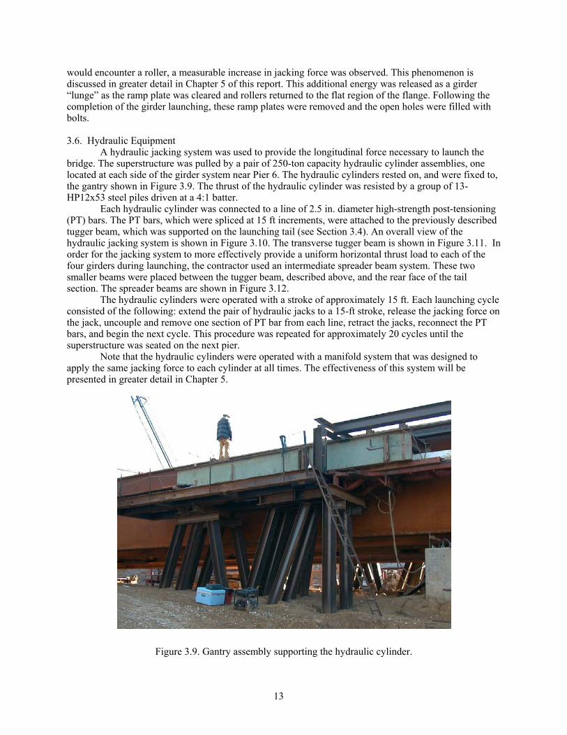
A hydraulic jacking system was used to provide the longitudinal force necessary to launch the bridge. The superstructure was pulled by a pair of 250-ton capacity hydraulic cylinder assemblies, one located at each side of the girder system near Pier 6. The hydraulic cylinders rested on, and were fixed to, the gantry shown in Figure 3.9. The thrust of the hydraulic cylinder was resisted by a group of 13-HP12x53 steel piles driven at a 4:1 batter.
Each hydraulic cylinder was connected to a line of 2.5 in. diameter high-strength post-tensioning (PT) bars. The PT bars, which were spliced at 15 ft increments, were attached to the previously described tugger beam, which was supported on the launching tail (see Section 3.4). An overall view of the hydraulic jacking system is shown in Figure 3.10. The transverse tugger beam is shown in Figure 3.11. In order for the jacking system to more effectively provide a uniform horizontal thrust load to each of the four girders during launching, the contractor used an intermediate spreader beam system. These two smaller beams were placed between the tugger beam, described above, and the rear face of the tail section. The spreader beams are shown in Figure 3.12.
The hydraulic cylinders were operated with a stroke of approximately 15 ft. Each launching cycle consisted of the following: extend the pair of hydraulic jacks to a 15-ft stroke, release the jacking force on the jack, uncouple and remove one section of PT bar from each line, retract the jacks, reconnect the PT bars, and begin the next cycle. This procedure was repeated for approximately 20 cycles until the superstructure was seated on the next pier.
Note that the hydraulic cylinders were operated with a manifold system that was designed to apply the same jacking force to each cylinder at all times. The effectiveness of this system will be presented in greater detail in Chapter 5.
Figure 3.9. Gantry assembly supporting the hydraulic cylinder.

14
Figure 3.10. Complete jacking system.
Figure 3.11. Rear of launching tail showing transverse tugger beam.

15
Figure 3.12. Spreader beams located between the tugger beam and the tail section.
3.7. Permanent Bridge Bearings The permanent bearings used to support the steel girders on the Iowa River Bridge, although not a
part of the actual launching system, deserve mention as they will be discussed as part of the instrumentation results presented in Section 5. The permanent bearings used at Piers 2 through 5 consist of steel pot bearings. In a pot bearing, the vertical reaction is supported by an elastomeric material that is contained in a steel cylinder or “pot”. The confinement of the elastomer allows the bearing to support a much greater load than would be possible with an unconfined elastomeric bearing. These bearings are rigidly connected to the steel girders through either a bolted connection as shown in the plans (see Figure 3.13), or, in some cases, through a welded connection. The final connection of the bearings to the girder flanges did not take place until after the final launch of the Westbound bridge. However, it is postulated that the high friction between the bearing and the girders could provide a very large resistance to horizontal force.
The permanent bearings at Piers 1 and 6 consist of steel expansion pot bearings. These bearings permit expansion and contraction movement over a range of 6 in. For movements exceeding this range, the bearings encounter a stop mechanism and begin to act like a fixed bearing.

16
Figure 3.13. Piers two through five permanent fixed pot-bearing details.

17
4. MONITORING PROGRAM 4.1. Introduction
The instrumentation used to monitor various aspects of the launching of the IRB is described in this chapter. Note that the naming conventions given in this chapter will be referenced in subsequent sections. It should be pointed out that the initiation of this monitoring program was very late in the project schedule. As such, the monitoring program was developed rather quickly with little input available from the designer.
In general, four types of data were collected: strain, deflection, tilt, and load. Not all types of data were collected during each launch. Rather, only those data that would aid in quantifying the structural behavior were collected. Regardless of the type of measurements made, data were collected at 4 Hz during active launching (i.e., only when the IRB was actually being pushed).
Unless otherwise noted, all strain readings will have been corrected for temperature variations. Sensors labeled with a preceding “T” represent gages not attached to the IRB, but rather attached to a representative unloaded piece of material. The actual temperature compensation process will be discussed in greater detail in Section 5.2.
Four individual launch events were monitored during the launch of the westbound IRB. These are designated WB1, WB3, WB4, and WB5. Launch WB1 was the first launch of the westbound roadway during which the first span of the roadway is launched from Pier 6 to Pier 5. Two launch events were monitored during the launch of the eastbound IRB. These are designated EB3 and EB4.
Specific locations along the girder train are designated by their “index point” or IP. The index point is simply the distance, measured in feet, from the Pier 1 bearing stiffener to any point on the bridge. An example of how these index points were marked along the edge of the girder bottom flange can be clearly seen in Figure 3.8. In this figure, the bolted splice ramp plate is shown at IP 171’.
4.2. Instrumentation of Westbound Roadway
Monitoring of the westbound bridge was performed during launches WB1, WB3, WB4, and WB5. Specific details of the instrumentation used during each launch are presented in the following sections. 4.2.1. Launch WB1
During launch WB1, a vertical cross-frame assembly and two girders were monitored. The vertical cross-frame at IP 135 ft was instrumented with 15 strain gages to assess the general behavior. Figure 4.1 shows the location and designation of these gages. The location and configuration of these gages were designed to allow for the determination of the internal forces induced in the members during launch operations as well as to allow the general behavior to be interpreted.
Girders C and D were monitored for longitudinal strain at IP 140.5 ft as shown in Figure 4.2. This general instrumentation layout was designed to allow an overall assessment of global girder behavior. 4.2.2. Launch WB3
During the WB3 launch, in which the launching nose landed on Pier 3, the concrete substructure at Pier 3, two roller assemblies at Pier 3, and two girders were monitored.
Pier 3 was instrumented, as shown in Figure 4.3, with a total of 12 strain gages, four deflection transducers, and two tilt sensors. Eight of the 12 strain gages were installed on each column near the base to measure the launch-induced behavior. An additional 4 gages were used to quantify temperature effects for the pier gages. Deflection transducers were placed near ground level to determine if the pier was moving longitudinally and/or laterally during launching. Tilt sensors were used to measure capbeam rotation as the girders were launched across the top of Pier 3.
Two of the four vertical bearing rollers at girder lines B and C were instrumented at Pier 3 (the “touchdown” pier for this launch) with 12 strain gages, as shown in Figures 4.4 and 4.5, to assess the level and type of forces induced in the pier during launching. The instrumentation package was developed to resolve the four force components that could potentially be induced at each roller assembly. As with

18
the pier instrumentation, an additional four strain gages were used to quantify temperature variations. The data from the rollers are not included in this report. A brief discussion of this is given in section 4.2.3.
c. Section B-B & D-D
112"
L 6 x 6 x 34
C
C
B
a. Section at IP 135'
WT 7x21.5 (Panel 3) WT 6x13 (Panel 2)
b. Section A-A
112"
W2
F2
112"
W1
112"
F1
112"
2
1
112"
3
11' -10" Typ.
A
A B
112"11
2"
112"
d. Section C-CF1F2
WT 6 x 20
W1W2
All gages are located at the mid-point
C
A
A
DD
BB
C
Girder A Girder CGirder B Girder D
Figure 4.1. Instrumentation of cross-frame members – Launch WB1.

19
8' -6"
2'-10" Typ.
GCTF1
GCBF1 GCBF2
GCW2GCW1
GCTF2
GDBF1 GDBF2
GDW1
GDTF1
GDW2
GDTF2
412"
1'-758"
1058"41
2"
3"
314" 31
4"
1'-334"
914"
134"
1058"
1'-758"
412" 41
2"
914"31
4"
1'-334"
314"
78" Typ.
214"
218"
Girder C Girder D
Figure 4.2. Instrumentation of Girders C and D – Launch WB1.

20
TemperatureStrain Gage (TSE)
23' -7"
Tilt Gage (BN) Tilt Gage (BS)
SW 90
23' -7"
Note: Same configuration on NE, NW and SE locations with corresponding designations.
3'5'-8"3'
Varies from
5' -7" to 9' -8"
1'
1'
Tilt Gage TN Tilt Gage TS
40"
Temperature Strain Gage (TNE)
Elev. 1082' -7"
Elev. 961' -3"
Elev. 967' -10"
1'
1'
3' 3'5'-8"
3'-6"
4'
N
a. Elevation
Northeast (NE) Gages
Southeast Gages (SE)
Southwest Gages (SW)
Drilled Shaft 8' dia.
Northwest Gages (NW)
b. Section A-A
Deflection Gage SWD
SW 90TSW 48
A A
45°
6"
Elevation 999' -3"
c. Detail B (Typ.)
Detail B
43'-1"21'-6"
5'-11"6'-7"
Temperature Strain Gage (TNW)
TemperatureStrain Gage (TSW)
Tilt Gage (SS)TiltGage (NN)
21'-6"
Figure 4.3. Instrumentation of Pier 3 – Launch WB3.

21
BNW
BNE
BSWBSE
1.5" Typ.
1'-7" Typ.
3.1" Typ.
6.5"1'-10"
2.5" Typ.
2'1" Typ.
Ø1'-6"
2'
1'-3"
b. Section B-B
PzPx
3.5"
PxPz
Py
B B
Launch Direction
Strain gages
2.5" Typ.
a. Roller Assembly B
Figure 4.4. Instrumentation of rollers B and C – Launch WB3 and WB4.
Figure 4.5. Typical strain transducer configuration on roller assembly.

22
Girders C and D were monitored at IP 219’ to assess the level and type of contact stresses that exist as the girders were rolled over the temporary launching rollers. A total of 13 gages were installed on each girder as shown in Figure 4.6. The gages installed on the girder web were oriented such that they measured vertical strain while the flange gages were oriented to measure longitudinal strain. It should be noted that gages CBF and DBF were destroyed when they were crushed by the respective rollers.
Roller
CNOBF
CNOF
CNMW
CNIF
CNBW
CNTW
DSOBF
DSBW
DSMW
DSTW
CSOBF
CBF Roller
DNOBF
DBF
DNOF
CSMW
CSTW
CSBWCSIF
CSOF
DNMW
DNBWDNIF
DNTW
DSIF DSOF27
8"
212"
212"
1'-758"
412"
114"
412"41
2"
6"
278"
78"
278"
212"
278"
212"
212"
118"
6"
1'-758"
78"
412"
212"
Girder C Girder D
Figure 4.6. Girder instrumentation at IP 219’ – Launch WB3.
4.2.3. Launch WB4
During the WB4 launch, in which the launching nose landed on Pier 2, the concrete substructure at Pier 2, along with two roller assemblies at Pier 2, were monitored.
Pier 2 was instrumented, as shown in Figure 4.7, with a total of 12 strain gages. Eight of the 12 strain gages were installed on each column near the base to measure vertical strain in the columns. Four additional gages were used to quantify temperature effects for the pier gages.
The vertical rollers beneath girders B and C were instrumented as shown in Figures 4.4 and 4.5 for launch WB3. As with launch WB3, the intent of this instrumentation was to quantify the launch forces.
From sensitivity studies performed with the field-collected data and from subsequent finite element modeling results, the instrumentation assumptions were shown to be highly sensitive. Therefore, results from the calculations for the roller instrumentation from Launches WB3 and WB 4 are not shown in this report. A roller is currently being tested in the laboratory to better understand the limitations of the calculation assumptions. When the testing is completed, the finite element model will be validated and will be used to calculate the applied launch forces. Those results will be provided in an addendum to this report to be distributed via the Iowa DOT Office of Bridges and Structures website. 4.2.4. Launch WB5 During the WB5 launch event, in which the launching nose landed on Pier 1, the vertical diaphragm at IP 1,322’-10” was monitored. Strain gages were located at third points of the members, as shown in Figure 4.8.

23
Elevation
Varies from
5' -7" to 9' -8"
3'
36 Nos.
HP 12 x 74
Section B-B
Northeast (NE)Strain Gages
1'
Northwest (NW) Strain Gages
TNW
TNE
3"
3' 5'-8"
Note: Same configuration on NE, NW and SE locations with corresponding designations.
NW 90
NW 48
Detail C (Typ.)
23' -7"3'-6"
4'
1'
1'
Southwest (SW) Strain Gages
Section A-A
N5'-8"
TSW
Southeast (SE)Strain Gages
TSE
42'-11"
Elev. 1080.25
Elev. 1020.83
Elev. 978.92
Elev. 984.92
21'-6"
A
6'-7"
23 -7"
A
21'-6"5'-11"
B
Detail C
B
3' 3'
Figure 4.7. Instrumentation of Pier 2 – Launch WB4.

24
112"
d. Section C-C
112"
b. Section A-A c. Section B-B and D-D
112"
112"
WT 7 x 21.5
112"
L 6 x 6 x 34
11' -10" Typ.
112"
C
a. Section at IP 1322' -10"
112" 11
2"
C
A
DD
A
112"
WT 6 x 20
All gages are located at the third points
BB2
1
1
1
122
2
Figure 4.8. Instrumentation of cross-frame members – Launch WB5.
4.3. Instrumentation of Eastbound Roadway Monitoring of the Eastbound bridge was performed during launches EB3 and EB4. Specific details of the instrumentation used during each launch are presented in the following sections. 4.3.1. Launch EB3
During the EB3 launch, in which the launching nose landed on Pier 3, the concrete substructure at Pier 3 was instrumented as shown in Figure 4.9 with a total of 11 strain gages. Ten of the 11 strain gages were installed on each column near the base to measure the launch-induced behavior. An additional gage was used to quantify temperature effects for the pier gages. 4.3.2. Launch EB4
During the EB4 launch, in which the launching nose landed on Pier 2, the concrete substructure at Pier 2 was instrumented as shown in Figure 4.10 with a total of 16 strain gages. Twelve of the 16 strain gages were installed on the pier columns near the base to measure vertical strain in the columns. Four additional gages were used to quantify effects for the pier gages.

25
23' -7"
SW 90
23' -7"
3'5'-8"3'
Varies from
5' -7" to 9' -8"
1'
1'
Elev. 1082' -7"
Elev. 961' -3"
Elev. 967' -10"
1'
1'
3' 3'5'-8"
7'-6"
N
a. Elevation
Northeast (NE) Gages
Southeast Gages (SE)
Southwest Gages (SW)
Drilled Shaft 8' dia.
Northwest Gages (NW)
b. Section A-A
SW 90T
A A
45°
6"
Elevation 999' -3"
d. Detail C (Typ.)
Detail C
21'-6"42'-11"21'-6"
5'-11"6'-7"
Detail B
TemperatureStrain Gage (TSW)
c. Detail B (Typ.) 6"
45°
NW 48NW 90T
NW 90
3'-6"
Figure 4.9. Instrumentation of Pier 3 – Launch EB3.

26
a. Elevation
Note: Same configuration on NE, NW and SE locations with corresponding designations.
3'
Varies from
5' -7" to 9' -8"
c. Section B-B
36 Nos. HP 12 x 74
Northeast (NE)Strain Gages
1'
TNW
Northwest (NW) Strain Gages
1'
TNE5'-8"3'
d. Detail C (Typ.)
6"
3'-6"45°
4'SW 48SW 90TSW 90 23' -7"
Southwest (SW) Strain Gages
3'
1'
1'
b. Section A-A
N5'-8"3'
TSW
Southeast (SE)Strain Gages
TSE
42'-11"
Elev. 1080' -6"
Elev. 1020' -10"
Piles
Elev. 984' -11"
Elev. 978' -11"
21'-6"
A
6'-7"5'-11"
21'-6"
A
23 -7"
B
Detail C
B
Figure 4.10. Instrumentation of Pier 2 – Launch EB4.

27
4.4. Data Collection Procedures Strain gages, data collection hardware, and wiring were installed prior to the start of each launch
event. Each time a launch operation was started (i.e., following a PT bar changeout) the data collection systems were started simultaneously, and the data was recorded continuously until launch operations were stopped. The IP marks described in section 4.1 were used to track the progress of the girders during launching operations. A hand-held device, or “clicker,” was activated each time an index point footmark passed the roller at Pier 6 to provide a permanent reference in all data files. In addition, notes of any unusual structural behavior during the launches were kept for future comparison with the collected data. 4.5. Steel Superstructure Position during Launch Events
A schematic view of the steel superstructure position, including pier, temporary roller bent, and field splice locations during stages of each launch event are presented in Figures 4.11 through 4.15. The launch distance referenced in each figure is actually the IP at Pier 6. These distances will be frequently referenced in Chapter 5.

28
Figu
re 4
.11.
Ele
vatio
n vi
ews o
f IR
B d
urin
g va
rious
stag
es o
f Lau
nche
s EB
1 an
d W
B1.

29
Figu
re 4
.11.
Con
tinue
d.

30
Figu
re 4
.12.
Ele
vatio
n vi
ews o
f IR
B d
urin
g va
rious
stag
es o
f Lau
nche
s EB
2 an
d W
B2.

31
Figu
re 4
.12.
Con
tinue
d.

32
Figu
re 4
.13.
Ele
vatio
n vi
ews o
f IR
B d
urin
g va
rious
stag
es o
f Lau
nche
s EB
3 an
d W
B3.

33
Figu
re 4
.13.
Con
tinue
d.

34
Figu
re 4
.14.
Ele
vatio
n vi
ews o
f IR
B d
urin
g va
rious
stag
es o
f Lau
nche
s EB
4 an
d W
B4.

35
Figu
re 4
.14.
Con
tinue
d.

36
Figu
re 4
.15.
Ele
vatio
n vi
ews o
f IR
B d
urin
g va
rious
stag
es o
f Lau
nche
s EB
5 an
d W
B5.

37
Figu
re 4
.15.
Con
tinue
d.

38
5. INSTRUMENTATION RESULTS
5.1. Introduction The collected superstructure and substructure data are presented and analyzed in this chapter.
The data and resulting discussion are grouped into four subsections: substructure behavior, jacking forces, girder behavior, and cross-frame behavior. 5.2. Substructure Behavior
Each of the four daylong launches were typically comprised of numerous individual 15 ft data segments because of the way the launch process was performed (i.e., 15 ft launch segments as previously described). The only exception to this was when a planned 15 ft launch segment was interrupted by hydraulic jack problems or other construction related issues. In those cases, some of the launch segment records represented less than 15 ft of movement. To represent the daylong record of the launch, the individual launch segment records (typically 15 ft) were stitched together during data processing. Figure 5.1 shows a representative set of these records for the EB3 Launch to illustrate the general content of the data prior to final processing. Each plot shows the NW and SW column face strains during the launch as a position of the launched roadway as shown in Figs. 4.11 through 4.15. Note, that these strain values have not been corrected for temperature effects (discussed subsequently).
The final processed day long records (corrected for temperature effects and stitched together) are presented in the following sections to illustrate the accumulation of pier column strain for the daylong launch process. In addition to presenting the daylong launch data for column strain, some selected 15 ft launch segments records are presented and discussed to illustrate some critical behavior in the columns associated with short-term events.
A data processing issue associated with the type of strain gages used to monitor the substructure is related to inherent temperature drift of the electrical signal. In short, the gages are sensitive to temperature changes. Therefore, the raw strain data could include both an actual strain component along with an unwanted temperature strain component. To obtain the actual strain component, a temperature compensation, or correction, was made. The temperature compensation was based on the use of the previously mentioned extra, or dummy, gage located at each of the four faces of the columns. The dummy gages were mounted to large pieces of concrete in the same way that the pier column gages were mounted to the concrete columns. A strain record was collected for each dummy gage at the same time that the column gages were recorded. The strain measured in the dummy gage at each of the four column faces (representing the temperature component) were subtracted from the column strain gages. A summary of the ambient temperature and associated weather data for each of the four day long launches is shown in Table 5.1.
Table 5.1. Weather data for the EB3, EB4, WB3 and WB4 Launches.
Launch Date Low High General Conditions Wind EB3 10/2/01 48°F 72°F Sunny and mild SW 10 mph EB4 10/17/01 30°F 59°F Cloudy and cool NW 10 mph WB3 2/19/02 39°F 48°F Foggy with light rain Calm to E 5 mph WB4 3/11/02 25°F 41°F Sunny and mild E-SE 10-15 mph
For convenience, the column axial and bending behavior plots in the following sections use strain
as the primary unit rather than stress, since strain was the unit of the collected data. Assuming that the pier concrete strength is 6.5 ksi and that the corresponding modulus of elasticity is E=4,700 ksi, a strain of 100 µε is equivalent to a stress of 470 psi in an uniaxial state.

39
760 765 770 775 780-60
-40
-20
0
20
40
60
810 815 820 825-60
-40
-20
0
20
40
60
825 830 835 840 845-60
-40
-20
0
20
40
60
910 915 920
-60
-40
-20
0
20
40
60
860 865 870 875-60
-40
-20
0
20
40
60
890 895 900 905 910-60
-40
-20
0
20
40
60
Stra
in (µ
ε)
Launch Distance (ft)
SW90 NW90
Stra
in (µ
ε)
Launch Distance (ft)
SW90 NW90
Stra
in (µ
ε)
Launch Distance (ft)
SW90 NW90
Stra
in (µ
ε)
Launch Distance (ft)
SW90 NW90
Stra
in (µ
ε)
Launch Distance (ft)
SW90 NW90
Stra
in (µ
ε)
Launch Distance (ft)
SW90 NW90
Figure 5.1. Representative sample of individual segmental concrete pier strain data for the EB3 Launch prior to temperature compensation and data stitching.

40
5.2.1. Pier 2 and Pier 3 column strain behavior during EB3, EB4, WB3 and WB4 Launches Figure 5.2 shows the daylong column strain records for each of the four launches. Shown are
column strain data during the EB3 and WB3 Launches (associated with Pier 3) and for the EB4 and WB4 Launches (associated with Pier 2). Only the strain data for column bending and axial strain are illustrated (i.e., strain data associated with torsion are not presented), and only the data at the 90 in. location are shown (i.e., the data at the 48 in. location are neglected). However, the data presented are representative of all of the data collected. As described in Chapter 4, the north column faces are designated NW and NE, respectively, for the west and east faces (west is in the direction of the launch). The south column designations are similarly SW and SE.
Note that for the EB3 launch, only one dummy gage was used. It was placed in the region of the SW column face. Thus, for the other three column faces (NW, SW, and SE), only the raw strain data are available for interpreting the pier behavior and they are not shown in Figure 5.2. For the other three launches, four dummy temperature gages were used, one at each gage location, and thus, the temperature-corrected strain data at all four column faces are shown.
Each plot in Figure 5.2 contains significant behavioral information. Some of the more significant of those behaviors are illustrated in the following paragraphs using day long records similar to those in Figure 5.2 and also more detailed, shorter segmental records associated with the individual 15 ft launch records.
It should be noted that the monitoring of each of the four launches was done independently of the others. This means that determining the total cumulative effect of the launching process on the pier columns was not possible and no attempt was made to do so. As shown in the daylong launch plots, after completion of a day long launch, there were typically “locked in” or residual strains. This is shown clearly for the NW and SW column faces in Figure 5.2b for the EB4 Launch, where at completion of the launch, the residual column strains were approximately 75 µε (350 psi). Whether these residual column strains in Pier 2 would be cumulative with strains developed in Pier 2 during the next launch was not addressed with this project. Based on Figure 5.2, the maximum measured column stresses during any of the four monitored launches were less than approximately 600 psi.
Figure 5.3 compares the daylong launch records for the EB3 and WB3 Launches for the SW column face and NW column face, respectively. Note that the overall Pier 3 column strain behavior for the two launches is extremely similar. In both cases, the launched steel is directly above the column shown. Figure 5.4 shows a similar comparison for the Pier 2 column strain behavior during the EB4 and WB4 Launches. This similarity in behavior at each of the piers was somewhat unexpected. It had been thought that the WB launch behavior might be different than the EB launch behavior since the launched EB roadway steel was already placed during the WB launch and likely would provide some translational restraint at the top of the pier not available during the EB launches. This was found to not be the case.
As shown in Figure 5.5, the day long accumulation of Pier 2 column strains during the WB4 Launch was significantly larger than the Pier 3 column strains developed during the WB3 Launch (this was also true for the EB4 vs. EB3 Launches). Due to the absence of applied horizontal launch force data on the individual pier cap it is difficult to conclude why this occurred. Had the launch forces for each launch been similar (as expected), one possible explanation for this would be that the point of fixity for the foundation for Pier 2 and Pier 3 were quite different. One implication could be that the point of fixity is lower for Pier 3 (drilled shaft foundation) than for Pier 2 (pile foundation). However, as will be discussed later in this section, a condition of reverse curvature in the Pier 3 column(s) could also be a source of reduced column strain. Figure 5.6 shows a typical segmental strain record for the WB4 launch for the NW and NE faces of the North column. Note the mirror image nature of the plots (centered about –30 µε). Basic engineering mechanics would indicate that the column strains were comprised of axial strain (compressive) from the steel superstructure dead load and bending strain from the applied horizontal launch forces at the top of the pier. In Figure 5.6, the axial strain component for both gages is approximately 30 µε compression (approximately 150 psi axial stress). The maximum bending strain is approximately 55 µε compression on the NW and 55 µε tension (approximately 250 psi) on the NE faces.

41
740 760 780 800 820 840 860 880 900 920 940
-150
-120
-90
-60
-30
0
30
60
Stra
in (µ
ε)
Launch Distance (ft)
SW90
(a) EB3 Launch
1050 1075 1100 1125 1150 1175 1200 1225-175
-150
-125
-100
-75
-50
-25
0
25
50
75
Stra
in (µ
ε)
Launch Distance (ft)
NW90 SW90 NE90 SE90
(b) EB4 Launch
Figure 5.2. Daylong concrete column strain records at Pier 2 and Pier 3 during EB3, EB4, WB3, and WB4 Launches.

42
725 750 775 800 825 850 875 900 925 950-175
-150
-125
-100
-75
-50
-25
0
25
50
75
Stra
in (µ
ε)
Launch Distance (ft)
NW90 SW90 NE90 SE90
(c) WB3 Launch
1050 1075 1100 1125 1150 1175 1200 1225-175
-150
-125
-100
-75
-50
-25
0
25
50
75
Stra
in (µ
ε)
Launch Distance (ft)
NW90 SW90 NE90 SE90
(d) WB4 Launch
Figure 5.2. Continued.

43
740 760 780 800 820 840 860 880 900 920 940-80
-60
-40
-20
0
20
40
60
80
Stra
in (µ
ε)
Launch Distance (ft)
SW90-EB3 NW90-WB3
Figure 5.3. Comparison of concrete column strain data for the EB3 and WB3 Launches.
1050 1075 1100 1125 1150 1175 1200 1225
-100
-75
-50
-25
0
25
50
Stra
in (µ
ε)
Launch Distance (ft)
NW90-WB4 SW90-EB4
Figure 5.4. Comparison of concrete column strain data for the EB4 and WB4 Launches.

44
725 750 775 800 825 850 875 900 925
1050 1075 1100 1125 1150 1175 1200 1225-175
-150
-125
-100
-75
-50
-25
0
25
50
75
Stra
in (µ
ε)
Launch Distance (ft)
NW90-WB4 NW90-WB3
Figure 5.5. Comparison of Pier 2 and Pier 3 concrete column strain data during the WB3 and WB4
Launches.
1160 1165 1170 1175 1180-90
-60
-30
0
30
Stra
in (µ
ε)
Launch Distance (ft)
NW90 NE90
Figure 5.6. Comparison of NW and NE concrete column strain data during the WB4 Launch.
Figure 5.7 shows a segmental strain record for the NW and SW faces during the WB4 Launch. As illustrated, the peak strain values were consistent in trend (time of occurrence) for all column faces (both the north and south columns) during this and all segments. Another typical behavior is found at the end of the launch record shown in Figure 5.7 where there is a tensile spike. This spike represents a relaxation or reduction of the compressive column strain due to the release of the hydraulic launch force at the

45
completion of a 15 ft launch segment. This spike would be compressive on the east column faces. Notice that the relaxation is larger for the NW face than for the SW face. This is intuitive as the applied launch force is directly above the north column.
1160 1165 1170 1175 1180-90
-80
-70
-60
-50
-40
-30St
rain
(µε)
Launch Distance (ft)
SW90 NW90
Figure 5.7. Comparison of NW and SW concrete column strain data during the WB4 Launch.
Although not easily seen in the day long strain records shown in Figure 5.2, a typical observation was that the column strain magnitudes, associated with peak values, were always larger in the column over which the roadway was launched. In other words, the south column strain magnitudes were larger than the north column magnitudes for the EB launches, and the north column magnitudes were larger than the south column for the WB launches. This is shown in a representative 15 ft segmental strain record for the NW and SW column faces for the WB3 Launch shown in Figure 5.8. Note that the peak strain values are largest on the NW face since the applied launch force was acting on the capbeam directly above the north column.
Some significant column strain changes during the launches are attributed to instantaneous events (e.g., the crossing of splice ramps at supports). Many of these instantaneous changes can be seen in the figures shown earlier for the day long launches. It’s noted that, in general, the instantaneous changes were larger for the EB launches than for the WB launches (see Figures 5.3 and 5.4). This could be due to several different effects, including the hydraulic system operators’ approach to advancing the launched steel over the ramp splices (e.g., there were several instances when the steel would lunge forward during a ramp splice crossing). Typically, for the WB launches, the operator slowed the steel down when crossing a splice ramp and tended to “creep” up on the ramp and then slowly ease down on the down side. This was generally not the case during the EB launches. It’s also possible that the EB roadway superstructure placement contributed to the reduced strains due to increased column restraint.

46
865 870 875 880-30
-25
-20
-15
-10
-5
0
5
10
Stra
in (µ
ε)
Launch Distance (ft)
SW90 NW90
Figure 5.8. Partial strain data for the SW and NW concrete column faces for the WB3 Launch.
Figure 5.9 shows a portion of the strain record for the NW and SW column faces during the WB3
Launch. This record represents a period near the beginning of the day long launch. Note the two events identified initially by a relatively large instantaneous change near the 769 ft location and a second one beginning at approximately 778 ft. The second event included a significant instantaneous change (or spike) with both a tensile and compressive component of change. These two events (which in reality are associated with one event) were relatively typical for all launches and are related to the crossing of a ramp splice over a support. In this case, the event occurred when a field splice (FS2; see Figure 4.13) crossed Pier 4. Figure 5.9 contains a schematic of the girder bottom flange splice plate (to scale and placed to show how the Pier 4 crossing corresponded with the column strain in Pier 3) including the up and down ramps. The length of the flat portion of the splice plate is approximately 8 ft, which corresponds to the region between the peaks shown in Figure 5.9. The complete event is characterized by 1) a large increase in column compressive strain to climb up the ramp, 2) relaxation of the launch force (and corresponding relaxation of column compressive strain) after reaching the flat surface of the splice, 3) movement of steel along the flat surface (note corresponding small change in column strain), and 4) lunging of the steel along the down side of the ramp splice (this “lunging” action was documented by visual observation during the launch). It is suspected that the relatively large inertial forces of the steel movement caused the initial compressive spike increase and corresponding tensile spike. Figure 5.10 shows another segmental strain record for the NW and SW faces during the WB4 Launch that shows similar behavior to that described above. However, in contrast to the above behavior, note that the two largest instantaneous changes (beginning at approximately 1,107 ft) occur over a much shorter distance (approximately less than 2 ft). This is because the source of the event (a bottom flange splice crossing at Pier 3) is a welded splice detail that is much shorter than the field splice noted above. Also, note that after each of the individual peaks (compressive instantaneous change and the tensile instantaneous change), the column didn’t always rebound to the same strain level that existed prior to the event. This is shown in Figure 5.10 after the two peaks.

47
770 775 780 785
-18
-12
-6
0
6
Stra
in (µ
ε)
Launch Distance (ft)
SW90 NW90
Figure 5.9. Concrete column strain during the passage of a bolted splice during the WB3 Launch.
1095 1100 1105 1110 1115
-30
-20
-10
0
10
20
Stra
in (µ
ε)
Launch Distance (ft)
SW90 NW90
Figure 5.10. Concrete column strain during the passage of a welded flange transition during the WB4
Launch.
The possible effect on pier column behavior due to the EB roadway steel being permanently located at the top of Piers 2 and 3 is illustrated in Figure 5.11. It had been assumed that during the WB launches, some possible translational restraint could occur at top of Pier 2 and Pier 3 (above the south columns) due to the already placed EB roadway. The figure shows a segmental strain record for the NW and SW faces during the WB4 launch. Note that the compressive instantaneous change (although not

48
relatively large compared to some other events) on the NW face is much more prominent than on the SW face. Also note that the tension/compression event was also prominent for the NW face but not for the SW face. This behavior was noted for both the WB3 and WB4 launches and suggests that there was possibly some translational restraint at the top of the south column (due to the previously placed EB roadway) during the launch. However, the behavior illustrated in Figure 5.11 occurred only during the latter part of the WB3 and WB4 launches. This suggests that the translational restraint only occurred after the EB roadway had engaged or taken up “slack” in the bearings. As described earlier in the report, the permanent EB roadway bearings had some inherent “slack” since not all of the bolts were in place and because the bolted connection used oversized holes in the bottom flange. Until the bolts enter a bearing condition, the faying surfaces can slip with respect to each other if the shear force exceeds the friction resistance between the plies. It is possible that the restrained condition is accomplished only after sufficient temperature expansion of the steel has placed the connection in a bearing state.
1130 1135 1140 1145-30
-25
-20
-15
-10
Stra
in (µ
ε)
Launch Distance (ft)
SW90 NW90
Figure 5.11. Strain data at the NW and SW concrete column faces during latter stages of the WB4
Launch.
Additionally, it was surprising the WB4 column strains were almost as large as those for the EB4 launch because of the expected translational restraint of the EB roadway steel. This suggests that other forces may have contributed to the large strains. It may be possible that temperature expansion forces from the EB roadway caused the pier to deflect throughout the launch.
Figure 5.12 shows a segmental strain record for the NW and SW faces during the WB4 launch. This is the last record at the end of the daylong launch. One unique occurrence of this launch relative to the other three launches was that the WB roadway was pushed approximately 4 ft past the typical stopping point in order to make sure a diaphragm would clear an obstruction in the launching pit. Recall that the slope of the bottom flange of the bridge girders is flat, whereas the bottom flange of the nose section was sloped. The flat surface of the bridge steel would likely allow rebound of the pier (in this case a tensile change in the NW and SW face strains) more easily than would the sloping nose surface (due to a reduced lateral resistance). With this in mind, note that there were two tensile spikes during the final 4 ft of the launch that could be representative of the column pier rebound. Note that the spikes were more pronounced for the north column than for the south column. This is intuitive as the north column would likely be displaced more due to the direct application of the launch force in the region, thus allowing for a greater rebound.

49
1210 1215 1220
-60
-50
-40
-30
-20
-10
Stra
in (µ
ε)
Launch Distance (ft)
SW90 NW90
Figure 5.12. Strain data at the NW and SW concrete column faces illustrating possible slip of pier near end of the WB4 Launch.
Figure 5.13 shows a NW and SW 15 ft launch strain record during the EB3 launch. The record is
near the end of the daylong launch. Note the steep tensile climb of both the NW and SW records at around 900 ft. This is somewhat similar to spikes that had been noted near the end of the WB4 launch and is likely indicative of a relaxation of the pier due to slippage under the launched steel. This behavior differs from that shown in Figure 5.12 in that the change is not as abrupt and suggests a less severe column strain relaxation. Figure 5.14 shows a partial record (the early part) of the EB4 launch for the SW and NW column faces. The gages at both the 48 in. and 90 in. locations are shown for both column faces. The torsion strain gage on the SW face is also shown. Note that at approximately 1,084 ft of the launch, a major change occurred in the bending strain on the NW face (at the 90 in. location). To a much lesser extent, the change is also noted for the gage at the 48 in. location. It’s interesting to note that this change occurred at the same time there was a significant change in the torsion gage strain. Observational notes taken during the launch indicate that, at this point in the launch, a major event occurred. As shown in Figure 4.13, the event was triggered by the crossing of a field splice (FS2) at Pier 3. One possible explanation is that a large force applied to the pier caused this significant torsion event. Documentation associated with other bridge launches perhaps provides some insight into this particular event. For example, during the EB5 Launch, it was documented that the girders at Pier 2 had drifted approximately 1.38 in. north of the desired centerline position. This was so pronounced that there was actually some noticeable temporary warping/rotation of the bottom flange of Girder E when this happened. That launch was suspended until misalignment could be fixed and it proceeded slowly until everything appeared to be in line.

50
890 895 900 905 910-60
-40
-20
0
20
40
60
Stra
in (µ
ε)
Launch Distance (ft)
SW90 NW90
Figure 5.13. Strain data at the NW and SW concrete column faces illustrating possible slip of pier near the end of the EB3 Launch.
The above described observation provides a reasonable explanation of an event that might have
caused the release of torsion in the columns noted in Figure 5.14. There were several documented cases where the contractor’s crew was not always able to keep the girders running right down the centerline. In these instances the girders were pushed transversely back to the centerline position using the guide rollers and hydraulic jacks at that pier. If the rollers at that pier were binding (due to either a “sticky” bearing or a roller that was not exactly perpendicular to the centerline of the girder) and causing the misalignment, there would be a tendency to induce torsion about the pier. This is especially true for the EB launches where there was no restraint from in-place girders. 5.2.2. Column tilt and deflection behavior during the WB3 Launch
In addition to the column strain data just presented, column tilts (referenced to a horizontal axis oriented along the direction of the launch) were measured at the Pier 3 capbeam and near the foundation. Deflections of the columns near the foundation were also measured (in both the longitudinal and transverse directions). Figures 5.15 and 5.16 show the column tilt data for Pier 3 at the top and bottom of the column, respectively. These data have been filtered to eliminate many of the small peak values that occur in the raw data to provide a general trend of behavior. Note that the magnitude of the tilt at the bottom is significantly less than the tilt at the top. Also, note that the absolute maximum tilt for the day long record occurred at the same launch distance (i.e., at 773 ft.) for the bottom and the top. This position of the steel superstructure represents the region where a field splice (FS2 in Figure 4.13) had crossed Pier 4 and induced uncontrolled movement of the steel (and subsequent large applied inertial force) on the down ramp of the field splice.

51
1065 1080 1095 1110
-120
-60
0
Stra
in (µ
ε)
Launch Distance (ft)
NW90 NW48 NW90T SW48 SW90
Figure 5.14. Strain data at the NW and SW concrete column faces during the EB4 Launch illustrating a
significant torsion event.
-0.8
-0.4
0
0.4
0.8
1.2
735 765 795 825 855 885 915
Launch Distance (ft.)
Tilt
(deg
.) .
TN
TS
Figure 5.15. Longitudinal tilt at the top of Pier 3 during the WB3 Launch.
A linear regression was performed on the day long records for each of the four tilt gages. Based on this, it is interesting to note that the overall trend in tilt for the top of the north and south columns and for the bottom of the south column is positive (0.053 degrees, 0.023 degrees, and 0.0257 degrees based on regression line, respectively), which implies accumulating tilt toward the west. In contrast, the overall trend in tilt for the bottom of the north column is negative (0.051 degrees based on regression line), which

52
implies accumulating tilt toward the east. The opposing sense of the tilt at the top and bottom of the north column implies reverse curvature in the column. It is speculated that this is one of the reasons for the relatively small column strain values measured at Pier 3 compared to those at Pier 2.
-0.15
-0.1
-0.05
0
0.05
0.1
0.15
0.2
0.25
735 765 795 825 855 885 915
Launch Distance (ft.)
Tilt
(deg
.) .
BN
BS
Figure 5.16. Longitudinal tilt at the bottom of Pier 3 during the WB3 Launch.
Figure 5.17 shows the daylong accumulation of deflection for Pier 3 near the foundation. The
deflection measured at the SW and NW column faces are in the west direction (i.e., the direction of the launch). Note that the deflections follow similar trends, but that in general, the north column deflection is greater than the south column deflection. Also, the deflection did not rebound at the end of the day long launch. Also, note that the two peak events near the end of the north column record do not occur at the south column.
The other deflections (NN and SS) are on the north and south column faces, respectively, and measure direction transverse to the launch direction. The deflection at the north column is toward the north and is larger than the deflection at the south column (which was toward the south).
Figure 5.18 shows a partial record of the WB3 launch for the SW and NW column faces along with the deflection of the Pier 3 foundation in the longitudinal direction at the SW and NW locations. It is interesting to note the relationship between the foundation deflection in the west direction and the strain event that occurred in the NW and SW column. Note that the foundation translation at the NW face rebounded but that the foundation at the SW face did not.
An interesting comparison between the measured column tilt (at the top of the north and the south columns) with the corresponding column strain (for the NW and SW faces) for the WB3 Launch is shown in Figure 5.19. Two significant instantaneous changes (peaks) in tilt values occurred at approximately 768 ft and at approximately 778 ft. Both of the peaks indicate movement of the top of the column (at the capbeam) toward the west and east. Although it can’t be seen because of the scale on the plot, the initial tilt movement is toward the west, followed by a movement to the east. Both of the peak tilt values correspond well with peak strain events at the same time. These events are associated with a field splice (FS2) crossing Pier 4 (see Figure 4.13 for the WB3 Launch). The first column strain compressive peak is during the movement of the pier up the splice ramp. The second peak, which shows both tensile and compressive tendencies, occurred as the splice moved off the splice plate along the down ramp. The indication of the tilt and column strain behavior is that there were inertial forces associated with the ramp

53
crossing (particularly during the down ramp stage) which caused some dynamic movement of the pier. Engineers on top of the pier validated this behavior through observations during similar events.
-0.07
-0.05
-0.03
-0.01
0.01
735 765 795 825 855 885 915
Launch Distance (ft)
Dis
plac
emen
t (in
.
NWD
SWDSSD
NND
Max. north deflection (-0.03 in. @ 906 ft.)
Max. west deflection (-0.06 @ 899 ft.)
Figure 5.17. Longitudinal deflection at the bottom of Pier 3 during the WB3 Launch.
800 805 810 815
-25
-20
-15
-10
-5
0
5
10
-0.06
-0.05
-0.04
-0.03
-0.02
-0.01
0.00
0.01
0.02
Stra
in (µ
ε)
Launch Distance (ft)
SW90 NW90
Disp
lace
men
t (in
)
SWD NWD
Figure 5.18. Strain data for the WB3 Launch at the NW and SW concrete column faces compared with longitudinal deflections of the Pier 3 foundation at the NW and SW locations.

54
765 770 775 780 785
-2
-1
0
1
765 770 775 780 785-30
0
30
Stra
in (µ
ε)
Launch Distance (ft)
NW90 SW90
Deg
rees
TN TS
Figure 5.19. Comparison of tilt at the top of the North and South columns of Pier 3 with strain at the NW
and SW concrete column faces during the WB3 Launch.
5.3. Jacking Forces
The hydraulic “pushing” forces measured during WB1 launch are shown in Figure 5.20. As can be seen in this figure, the south ram imposed a greater force than the north ram. This is, as one would expect, as the hydraulic equipment was located on the south side of the bridge and would therefore experience smaller hydraulic loss. In general, the force levels in each ram tracked the other. In other words, when one ram had an increasing load, the other ram did as well. Approximately every 15 ft, the force in both rams returned to zero. This 15 ft coincides with the 15 ft launch increments previously described.
Several notable “spikes” in the load levels can also be observed at approximate launch distances 45 ft, 75 ft, 165 ft, 260 ft, and 285 ft. In all cases, these “spikes” can be attributed to a change in girder geometry passing over a roller. Table 5.2 summarizes the likely cause of the “spike.” Also, note that the load generally increased from launch distance from 165 to 260. This gradual increase in load is due to the increased force required to “lift” the nose assembly after touchdown occurred on Pier 5. The hydraulic “pushing” forces measured during Launch 3 of the Westbound IRB are shown in Figure 5.21. As can be seen in this figure, the south ram imposed a greater load than the north ram. This is, as one would expect, and as was shown previously for Launch 1, as the hydraulic equipment was located on the south side of the bridge and would therefore experience smaller hydraulic loss.
In general, the force levels in each ram tracked the other. In other words, when one ram had an increasing load, the other ram did as well. Several notable “spikes” in the load levels can also be observed at approximate launch distances 765 ft, 795 ft, and 803 ft. In all cases, these “spikes” can be attributed to a change in girder geometry passing over a roller.
Table 5.3 summarizes the likely cause of the “spike.” Also, note that the load generally stayed constant from the beginning of the launch to approximately launch distance 764 ft. At this point, the load gradually increased. This gradual increase in load is due to the increased force required to “lift” the nose assembly after touchdown occurred on Pier 3.
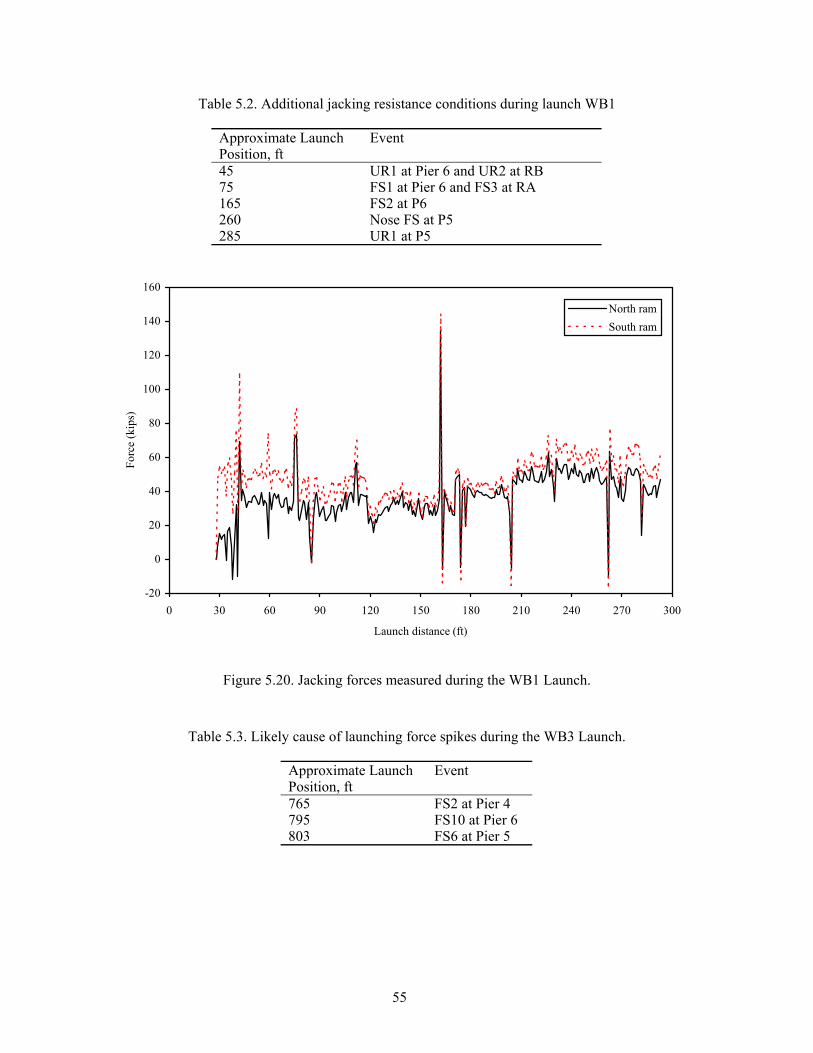
55
Table 5.2. Additional jacking resistance conditions during launch WB1
Figure 5.20. Jacking forces measured during the WB1 Launch.
Table 5.3. Likely cause of launching force spikes during the WB3 Launch.
Approximate Launch Position, ft
Event
765 FS2 at Pier 4 795 FS10 at Pier 6 803 FS6 at Pier 5
Approximate Launch Position, ft
Event
45 UR1 at Pier 6 and UR2 at RB 75 FS1 at Pier 6 and FS3 at RA 165 FS2 at P6 260 Nose FS at P5 285 UR1 at P5
-20
0
20
40
60
80
100
120
140
160
0 30 60 90 120 150 180 210 240 270 300
Launch distance (ft)
Forc
e (k
ips)
North ramSouth ram

56
-50
0
50
100
150
200
250
730 750 770 790 810 830 850 870Launch distance (ft)
Forc
e (K
ips)
North Ram
South Ram
Figure 5.21. Jacking forces measured during the WB3 Launch.
5.4. Girder Behavior
Figure 5.22 shows the change in strain history for the gages located on Girders C and D during launch WB1. Recall that initially the gages were located approximately 74 ft from RA and 107 ft from Pier 6 (approximately 0.41 point in span), which, by classic beam theory, should be a positive moment region.
As can be seen in Figure 5.22 as the instrumented section is launched towards Pier 6, the section experiences an increasing negative moment as indicated by the positive strain values on the top flange and negative strain values on the bottom flange. This trend continues until launch distance 135, where the instrumented section is directly over Pier 6. At that point, the strain values remain more or less constant until launch position 165, which coincides with the point where the nose assembly touched down on Pier 5. During this period, (i.e., launch distance 135 to 165) the instrumented section is in the cantilevered section of girder and is subject to constant moment.
Once the nose assembly reaches Pier 5, the cantilever section is converted to the end span of a continuous girder section. As such, the bending moment at the instrumented section would be subject to an increasingly positive moment. This is verified by the change in strain experienced from point launching distance 165 to the end of the launch.
The general behavior of Girders C and D are quite similar, as shown in Figure 5.22. However, there is a difference in the strain (and resulting stress) levels experienced in the top and bottom flanges of each girder. Girder C had strain levels in the top and bottom flanges that correlate with 35 ksi and –16 ksi maximum stress levels, respectively. Girder D, on the other hand, had strain levels that correlate with 30 ksi and –22 ksi maximum stresses in the top and bottom flanges, respectively. Interestingly, these two conditions result in stress differential (stress in top flange minus stress in bottom flange) of just over 50 ksi for each girder. This behavior would indicate that the neutral axis in girder D is closer to the top flange than in girder C. This difference is likely due to the differing flange plate thickness between the two girders.
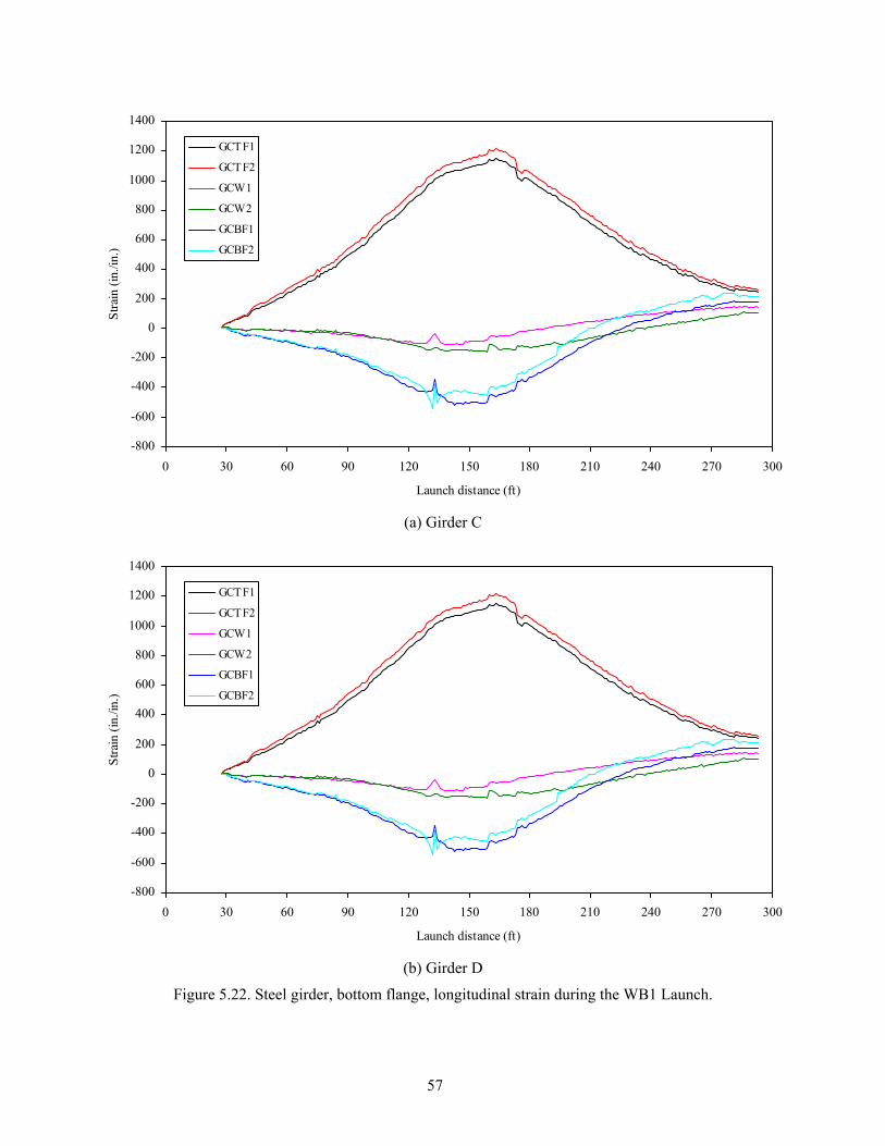
57
(a) Girder C
(b) Girder D
Figure 5.22. Steel girder, bottom flange, longitudinal strain during the WB1 Launch.
-800
-600
-400
-200
0
200
400
600
800
1000
1200
1400
0 30 60 90 120 150 180 210 240 270 300
Launch distance (ft)
Stra
in (i
n./in
.)
GCTF1
GCTF2
GCW1
GCW2
GCBF1
GCBF2
-800
-600
-400
-200
0
200
400
600
800
1000
1200
1400
0 30 60 90 120 150 180 210 240 270 300
Launch distance (ft)
Stra
in (i
n./in
.)
GCTF1
GCTF2
GCW1
GCW2
GCBF1
GCBF2

58
Figures 5.23 and 5.24 show the longitudinal strain profile through the depth of Girders C and D
for various launch distances. As can be seen, the strain profile was, for the most part, linear in both girders up to launch distance 165. At that point, which coincides with the point the nose assembly touched down on Pier 5, both girders began to experience non-linear strain distributions. The non-linearity was most severe in girder C. The non-linearity is maximized between launch distances 225 and 255 which is the period in which girders A and D approached Pier 5. This general behavior indicates that girder D is causing notable out-of-plane strains in girder C. Additionally, the fact that the nose was attached to Girders B and C only could be a source of the nonlinear distribution.
Figures 5.25 through 5.31 summarize the strain response for the longitudinally oriented gages placed on the top and bottom of the bottom flange of girders C and D during Launch WB3. From the beginning of the launch up to the point where the instrumented section reached Pier 6, the global behavior is much as one would expect. As the gages were initially in a negative moment region, one would expect a concave downward shaped plot. This is as was observed in all cases. However, the global behavior after passing over Pier 6 is not as one would expect. Specifically, one would have expected the negative moment to have been maximized at that point and that the strain levels should have become less negative. This is not what was observed. The strains did not begin to increase until approximately launch distance 842 ft. Unfortunately, with only the data collected, the cause of this could not be determined. However, it is speculated that some force, other than primary bending, is likely the cause.
In the region very close to Pier 6, the local behavior also illustrated in Figures 5.25 through 5.31 is quite interesting. As one would expect, a highly localized region is exposed to very high loads and, as a result, very high strain responses were recorded. Interestingly, where the global strains on the top and bottom of the bottom flange generally followed the same pattern in the localized region, there is significant deviation. For example, the general trend was for the gages on the top of the bottom flange to exhibit a strain history that was concave down whereas the gages on the bottom of the bottom flange had a concave up history. This is indicative that the bottom flange was subjected to very large localized bending. As can be seen, the strain was not constant across the width of the bottom flange (either during global or local behavior). This indicates that either the roller was offset from the centerline of the girder and/or a lateral force was being imposed on the bottom flange. Also, as can be seen, the distribution of strain across the width of the bottom flange tended to be nearly linear at locations away from Pier 6, but was highly non-linear near Pier 6. Further, it can be seen that the “slope” of the strain profile across the flange width is in opposite directions for Girders C and D. As can be seen in Figures 5.28 and 5.29, the strain gage, on Girders C and D respectively, that was immediately in line with the roller, experienced very high strain levels as the girder passed over the roller (approximately 4390 µε and 7634 µε, respectively). In a uniaxial, elastic stress condition, these strain levels would represent stresses of 127 ksi and 221 ksi, respectively.

59
(a) Launch distances 45 ft, 75 ft, 105 ft, 135 ft, and 165 ft
(b) Launch distances 165 ft, 195 ft, 225 ft, 255 ft, and 294 ft
Figure 5.23. Steel girder longitudinal strain profile for Girder C during the WB1 Launch.
0
20
40
60
80
100
120
140
160
-600 -400 -200 0 200 400 600 800 1000 1200
Strain (µε)
Dis
tanc
e fr
om b
otto
m su
rfac
e of
bot
tom
flan
ge (i
n.) 45 ft
75 ft105 ft135 ft165 ft
0
20
40
60
80
100
120
140
160
-600 -400 -200 0 200 400 600 800 1000 1200
Strain (µε)
Dis
tanc
e fr
om b
otto
m su
rfac
e of
bot
tom
flan
ge (i
n.) 165 ft
195 ft225 ft255 ft294 ft

60
(a) Launch distances 45 ft, 75 ft, 105 ft, 135 ft, and 165 ft
(b) Launch distances 165 ft, 195 ft, 225 ft, 255 ft, and 294 ft
Figure 5.24. Steel girder longitudinal strain profile for Girder D during the WB1 Launch.
0
20
40
60
80
100
120
140
160
-600 -400 -200 0 200 400 600 800 1000 1200
Strain (µε)
Dis
tanc
e fr
om b
otto
m su
rfac
e of
bot
tom
flan
ge (i
n.) 45ft
75ft105ft135ft165ft
0
20
40
60
80
100
120
140
160
-600 -400 -200 0 200 400 600 800 1000 1200
Strain (µε)
Dis
tanc
e fr
om b
otto
m su
rfac
e of
bot
tom
flan
ge (i
n.) 165ft
195ft225ft255ft294ft

61
(a) Launch distance 735 to 854 ft
(b) Launch distance from 823 to 824 ft
Figure 5.25. Longitudinal strain at the upper surface of the Girder C bottom flange (steel) during the WB3 Launch.
GSIF
GSOF
GNIF
CNOF Roller C @ Pier 6
L
-1000
-800
-600
-400
-200
0
200
400
600
800
1000
730 750 770 790 810 830 850 870
Launch distance (ft)
Stra
in (µε)
CSOF
CSIF
CNIF
CNOF
CL of Roller @ Pier 6
-1000
-800
-600
-400
-200
0
200
400
600
800
1000
823 823.25 823.5 823.75 824
Launch distance (ft)
Stra
in (µε)
CSOF
CSIF
CNIF
CNOF
CL of Roller @ Pier 6

62
(a) Launch distance from 735 to 854 ft
(b) Launch distance from 823 to 824 ft
Figure 5.26. Longitudinal strain at the upper surface of the Girder D bottom flange (steel) during the WB3 Launch.
GSIF
GSOF
GNIF
CNOF Roller C @ Pier 6
L
-1000
-800
-600
-400
-200
0
200
400
600
800
1000
730 750 770 790 810 830 850 870Launch distance (ft)
Stra
in (µε)
DSOF
DSIF
DNOF
CL of Roller @ Pier 6
-1000
-800
-600
-400
-200
0
200
400
600
800
1000
823 823.25 823.5 823.75 824Launch distance (ft)
Stra
in (µε)
DSOFDSIFDNOF
CL of Roller @ Pier 6
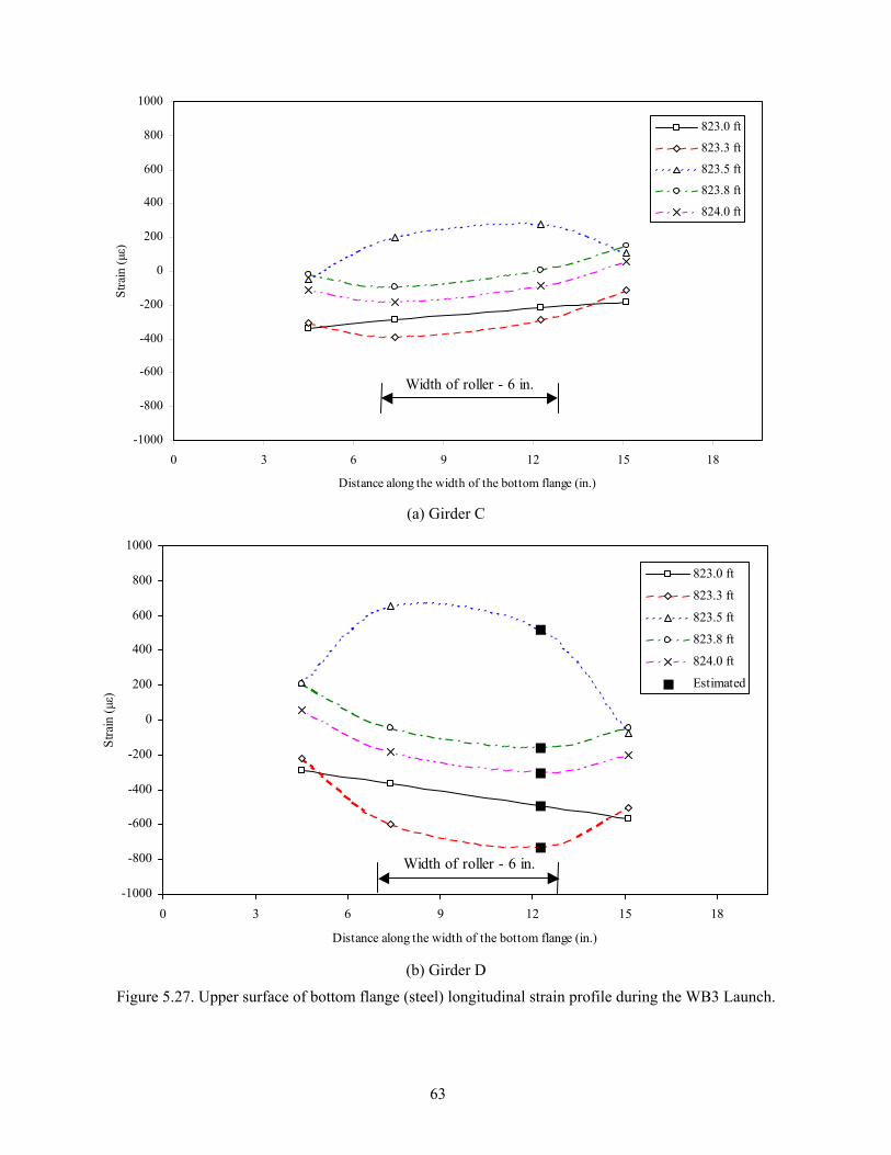
63
(a) Girder C
(b) Girder D
Figure 5.27. Upper surface of bottom flange (steel) longitudinal strain profile during the WB3 Launch.
-1000
-800
-600
-400
-200
0
200
400
600
800
1000
0 3 6 9 12 15 18
Distance along the width of the bottom flange (in.)
Stra
in (µε)
823.0 ft
823.3 ft
823.5 ft
823.8 ft
824.0 ft
Estimated
Width of roller - 6 in.
-1000
-800
-600
-400
-200
0
200
400
600
800
1000
0 3 6 9 12 15 18
Distance along the width of the bottom flange (in.)
Stra
in (µε)
823.0 ft
823.3 ft
823.5 ft
823.8 ft
824.0 ft
Width of roller - 6 in.

64
(a) Launch distance from 735 to 854 ft
(b) Launch distance from 823 to 824 ft
Figure 5.28. Longitudinal strain at the bottom surface of the Girder C bottom flange (steel) during the WB3 Launch.
CBF
CNOBF
CSOBF
Roller C @ Pier 6
L
Roller C @ Pier 6
L
CBF
CNOBF
CSOBF
-1000
-800
-600
-400
-200
0
200
400
600
800
1000
730 750 770 790 810 830 850 870
Launch distance (ft)
Stra
in (µε)
CSOBF
CBF
CNOBF
CL of Roller @ Pier 6
-1000
-800
-600
-400
-200
0
200
400
600
800
1000
823 823.25 823.5 823.75 824
Launch distance (ft)
Stra
in (µε)
CSOBF
CBF
CNOBF
-4390 µε
CL of Roller @ Pier 6

65
(a) Launch distance from 735 to 854 ft
(b) Launch distance from 823 to 824 ft
Figure 5.29. Longitudinal strain at the bottom surface of the Girder D bottom flange (steel) during the WB3 Launch
-1000
-800
-600
-400
-200
0
200
400
600
800
1000
823 823.25 823.5 823.75 824
Launch distance (ft)
Stra
in (µε)
DSOBF
DBF
DNOBF
-7634 µε CL of Roller @ Pier 6
-1000
-800
-600
-400
-200
0
200
400
600
800
1000
730 750 770 790 810 830 850 870
Launch distance (ft)
Stra
in (µε)
DSOBF
DBF
DNOBF
CL of Roller @ Pier 6

66
-1000
-800
-600
-400
-200
0
200
400
600
800
1000
0 3 6 9 12 15 18
Distance along the width of the bottom flange (in.)
Stra
in (µε)
823.0 ft
823.3 ft
823.8 ft
824.0 ft
Width of roller
(a) Launch distance at 823.0, 823.3, 823.8, and 824.0 ft
-9000
-8000
-7000
-6000
-5000
-4000
-3000
-2000
-1000
0
1000
0 3 6 9 12 15 18
Distance along the width of the bottom flange (in.)
Stra
in (µε)
823.5 ft
Width of roller
(b) Launch distance at 823.5 ft
Figure 5.30. Lower surface of bottom flange (steel) longitudinal strain profile for Girder C during the WB3 Launch.
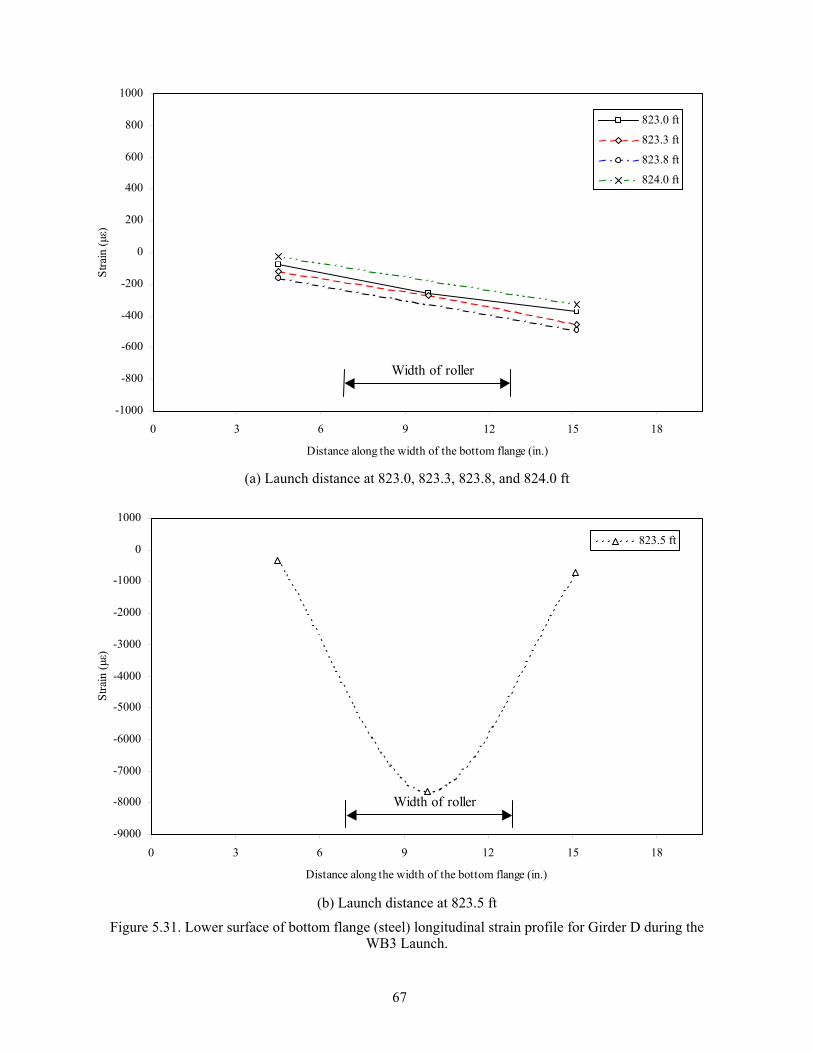
67
(a) Launch distance at 823.0, 823.3, 823.8, and 824.0 ft
(b) Launch distance at 823.5 ft
Figure 5.31. Lower surface of bottom flange (steel) longitudinal strain profile for Girder D during the WB3 Launch.
-1000
-800
-600
-400
-200
0
200
400
600
800
1000
0 3 6 9 12 15 18
Distance along the width of the bottom flange (in.)
Stra
in (µε)
823.0 ft
823.3 ft
823.8 ft
824.0 ft
Width of roller
-9000
-8000
-7000
-6000
-5000
-4000
-3000
-2000
-1000
0
1000
0 3 6 9 12 15 18
Distance along the width of the bottom flange (in.)
Stra
in (µε)
823.5 ft
Width of roller

68
Figures 5.32 through 5.34 summarize the vertical strain behavior in the lower portion of the Girder C and D webs during Launch 3. As one would expect, there was very little vertical strain in the web when the instrumentation was away from Pier 6. However, as the gages approached the Pier 6 roller, the vertical strains were increased dramatically to approximately 850 microstrain and 1500 microstrain in Girder C and D, respectively. As has been presented previously, the web gages were located 2.5 in. above the web-to-bottom flange interface. It is highly likely that the vertical strain at that interface (and below) would be higher than that measured at 2.5 in. To estimate what these values might be, the data collected from the installed gages were used to extrapolate the results downward as shown in Figure 5.34. When extrapolated, one finds that the vertical strain at the web-to-bottom flange interface is in the range of 1250-1300 µε (compression) in Girder C and 1800-2000 µε (compression) for Girder D. For an uniaxial, elastic state of stress, these strain values would represent stresses between approximately 52 ksi and 59 ksi (note: web yield strength = 50 ksi). 5.5. Crossframe Behavior
In order to better understand the types and magnitudes of forces induced in the secondary bracing of the IRB during launching, several cross-brace members were monitored during Launches WB1 and WB5. During Launch WB1, 7 members were monitored as illustrated in Figure 4.1 and similarly, during Launch WB5, 4 members were monitored as shown in Figure 4.8 In order to fully understand the behavior of these members, a number of gages (either 3 or 4 as appropriate) were used to fully interpret the behavior. The axial and bending forces could be determined from the data collected from these gages. In addition, peak strains (which are directly related to peak stresses) could also be determined at the extremes of each member (i.e., member tips near the end of each member. However, it must be firmly established that the techniques employed to determine the member forces are hypersensitive to natural errors present in strain gages. As such, the axial force data presented in the following figures and tables should be considered to only represent general trends in axial force and for considering relative magnitudes of forces present in individual members. Figures 5.35 and 5.36 show typical cross-frame behavior information for launches WB1 and WB5, respectively. Figure 5.35 graphically summarizes the raw strain data (i.e., as collected from the instrumentation), strain at the member tips at the instrumented section (as interpolated from the raw strain data), and the internal member forces (e.g., axial and biaxial bending components) determined from the raw strain data for Section A-A between Girders C and D during Launch WB1 (see Figure 4.1). Similarly, Figure 5.36 shows the raw strain data, strain at the member tips at the instrumented section, strain at the member tips near the end of the member, and the member forces for member A1 during Launch WB5. As can be seen from comparing these two plots, the behavior of the cross-frames is quite different during the two launches indicating a complex and almost random behavior. Although an extensive evaluation and analysis of the cross-frame data was completed, no patterns of girder position, timing of significant launch “events”, or other factors could be identified. To further compare launches WB1 and WB5, Tables 5.4 and 5.5 summarize several important pieces of information for all members monitored during the two launches. It is apparent that the magnitude of the forces present is very high, and considering the fact that in many cases the cross-frame members experienced both “positive” and “negative” forces, it is clear that the behavior of these members is quite complex. In addition, it should be pointed out that in no instance were strains that exceeded yield experienced. However, a peak strain corresponding to approximately 33 ksi was determined in one member.

69
(a) Launch distance from 735 to 854 ft
(b) Launch distance from 823 to 824 ft
Figure 5.32. Vertical strain in the lower portion of the Girder C steel web plate during the WB3 Launch.
-1800
-1500
-1200
-900
-600
-300
0
300
600
730 750 770 790 810 830 850 870
Launch distance (ft)
Stra
in (µε)
CNTW
CNMW
CNBW
CSTW
CSMW
CSBW
CL of Roller @ Pier 6
-1800
-1500
-1200
-900
-600
-300
0
300
600
823 823.25 823.5 823.75 824
Launch distance (ft)
Stra
in (µε)
CNTW
CNMW
CNBW
CSTW
CSMW
CSBW
CL of Roller @ Pier 6

70
(a) Launch distance from 735 to 854 ft
(b) Launch distance from 823 to 824 ft
Figure 5.33. Vertical strain in the lower portion of the Girder D steel web plate during the WB3 Launch.
-1800
-1500
-1200
-900
-600
-300
0
300
600
730 750 770 790 810 830 850 870Launch distance (ft)
(a)
Stra
in (µε)
DNTW
DNBW
DSTW
DSMW
DSBWCL of Roller @ Pier 6
-1800
-1500
-1200
-900
-600
-300
0
300
600
823 823.25 823.5 823.75 824Launch distance (ft)
(a)
Stra
in (µε)
DNTW
DNBW
DSTW
DSMW
DSBW
CL of Roller @ Pier 6

71
-2100
-1800
-1500
-1200
-900
-600
-300
0
300
600
0.00 1.25 2.50 3.75 5.00 6.25 7.50 8.75 10.00
Distance above bottom surface of the bottom flange (in.)
Stra
in (µε)
CN-823.0 ftCS-823.0 ftCN-823.3 ftCS-823.3 ftCN-823.5 ftCS-823.5 ftCN-823.8 ftCS-823.8 ftCN-824.0 ftCS-824.0 ft
(a) Girder C
-2100
-1800
-1500
-1200
-900
-600
-300
0
300
600
0.00 1.25 2.50 3.75 5.00 6.25 7.50 8.75 10.00
Distance above bottom surface of the bottom flange (in.)
Stra
in (µε)
DN-823.0 ftDS-823.0 ftDN-823.3 ftDS-823.3 ftDN-823.5 ftDS-823.5 ftDN-823.8 ftDS-823.8 ftDN-824.0 ftDS-824.0 ft
(b) Girder D
Figure 5.34. Vertical strain profile in lower part of steel girder web plate during the WB3 Launch.
-1257 µε -1287 µε
-2037 µε
-1838 µε
Web to Bottom flange interface
Web to Bottom flange interface
-1257 µε -1287 µε
-2037 µε
-1838 µε
Web to Bottom flange interface
Web to Bottom flange interface

72
-200
-100
0
100
200
300
400
0 50 100 150 200 250 300
Launch distance (ft)
Stra
in (µε
)3AF13AF23AW13AW2
(a) Strain at gage locations
-200
-100
0
100
200
300
400
0 50 100 150 200 250 300
Launch distance (ft)
Stra
in (µε
)
3AFT13AFT23AWT13AWT2
(b) Strain at section tips
Figure 5.35. Typical steel cross-frame behavior at Section A of panel 3 during the WB1 Launch.

73
-20
-15
-10
-5
0
5
10
15
20
0 30 60 90 120 150 180 210 240 270 300
Launch distance (ft)
Mom
ent (
in-k
)
-10
0
10
20
30
40
50
Forc
e (K
ips)
3AMx3AMy3AP
(c) Internal Forces
Figure 5.35. Continued.

74
-200
0
200
400
600
800
1000
1200 1225 1250 1275 1300 1325 1350 1375 1400
Launch distance (ft)
Stra
in (µε
)A1F1A1F2A1W1A1W2
(a) Strain at gage locations.
-200
0
200
400
600
800
1000
1200 1225 1250 1275 1300 1325 1350 1375 1400
Launch distance (ft)
Stra
in (µε
)
A1FT1A1FT2A1WT1A1WT2
(b) Strain Section A1 member tips.
Figure 5.36. Typical steel cross-frame behavior at Section A during the WB5 Launch.

75
-400
-200
0
200
400
600
800
1000
1200
1200 1225 1250 1275 1300 1325 1350 1375 1400
Launch distance (ft)
Stra
in (µε
)AFT1@S 4dAFT2@S 4dAWT1@S 4dAWT2@S 4d
(c) Extrapolated strain values at tips of southern most member end.
-80
-60
-40
-20
0
20
40
1200 1225 1250 1275 1300 1325 1350 1375 1400
Launch distance (ft)
Mom
ent (
in-k
)
0
20
40
60
80
100
Forc
e (K
ips)
A1MxA1MyA1P
(d) Internal forces
Figure 5.36. (Continued)

76
Table 5.4. Launch WB1 cross-frame member behavior.
Member forces Peak strain at
gage Section tip Peak tip strainAxial, P Bending, Mx Bending,
My Max. Min. Max. Min. Max. Min. Max. Min. Max. Min.Pa
nel
Sect
ion
Gage
µε µε location
µε µε k k ft-k ft-k ft-k ft-k AF1 170.0 -295.6 AFT1 188.5 -280.8AF2 126.9 -330.1 AFT2 108.3 -344.9AW1 86.2 -200.0 AWT1 85.3 -146.6
A
AW2 110.9 -168.8 AWT2 84.3 -147.1
15.3 -30.1 0.3 -0.9 0.3 0.0
B1 113.3 -216.8 BT1 112.1 -167.5B2 118.3 -315.3 BT2 125.0 -364.6B B3 218.0 0.0 BT3 400.5 0.0
34.1 -21.1 2.9 -0.2 7.3 -0.1
CF1 513.7 0.0 CFT1 511.0 0.0 CF2 565.4 0.0 CFT2 594.2 0.0 CW1 534.6 0.0 CWT1 587.5 0.0
2
C
CW2 540.8 0.0 CWT2 590.9 0.0
89.1 0.0 1.3 -1.0 1.3 -0.1
AF1 221.8 -61.6 AFT1 208.8 -61.6 AF2 266.7 -6.4 AFT2 284.8 -6.8 AW1 189.8 -32.1 AWT1 213.0 -42.0
A
AW2 251.3 -12.8 AWT2 216.6 -37.0
42.6 -3.21 0.7 -0.3 0.1 -1.0
B1 393.7 0.0 BT1 405.2 0.0 B2 370.6 0.0 BT2 359.0 -1.9 B B3 136.7 -9.9 BT3 124.0 -127.9
56.2 0.0 0.0 -3.8 0.0 -5.8
CF1 165.1 -1.2 CFT1 146.5 -2.8 CF2 151.5 -6.2 CFT2 166.8 -42.4 CW1 324.0 -6.2 CWT1 399.1 -5.4
C
CW2 341.2 -1.2 CWT2 398.3 -5.3
31.1 -0.1 2.2 -0.4 0.7 -0.4
D1 185.9 -248.8 DT1 175.7 -219.3D2 206.5 -307.8 DT2 217.4 -337.2
3
D D3 246.2 0.0 DT3 344.1 -1.9
53 -25.2 3.2 0.0 6.9 0.0

77
Table 5.5. Launch WB5 cross-frame member behavior.
Peak tip strain Peak strain Member forces Peak strain at
gage Section tipat section at member end Axial, P Bending, Mx Bending, My
Max. Min. Max. Min. Max. Min. Max. Min. Max. Min. Max. Min.
Mem
ber
Sect
ion
Gage
µε µε Location
µε µε
Memberend
µε µε k k ft-k ft-k ft-k ft-k A1F1 313.8 0.0 A1FT1 180.7 -82.5A1F2 757.4 15.6 A1FT2 890.4 18.2
AFT1 192.8 -192.2
A1W1 280.1 9.6 A1WT1 185.8 6.8 A1
A1W2 265.7 10.8 A1WT2 212.3 9.6 AFT2 1093.3 -117.0
86.2 2.1 2.6 0.0 -0.1 -5.4
A2F1 391.9 13.2 A2F1 410.7 14.0 A2F2 329.4 10.8 A2F2 310.6 9.7
AWT1 379.2 6.0
A2W1 282.5 12.0 A2W1 236.2 6.1
A
A2
A2W2 241.6 6.0 A2W2 232.5 5.5 AWT2 268.5 -232.9
61.6 2.23 1.3 0.0 0.7 -0.2
B11 217.6 -441.2 B1T1 188.7 -625.1B12 217.6 -301.7 B1T2 346.5 -41.8
BT1 1474.9 -91.9
B13 542.2 15.6 B1T3 943.0 15.8 B1
B14 658.8 16.8 BT2 1168.0 -377.5
77.2 3.29 13.2 -0.2 15.0 -0.9
B21 553.0 14.4 B2T1 745.6 17.6 B22 208.0 -556.6 B2T2 212.2 -852.9
BT3 253.0 -198.7
B23 186.3 -480.9 B2T3 433.4 -8.8
B
B2
B24 95.0 4.8
55.2 -15.8 -0.1 -8.3 5.3 -4.1
C1F1 211.6 -466.4 C1FT1 226.5 -559.2C1F2 203.2 -366.7 C1FT2 213.1 -399.4
CFT1 595.8 -855.6
C1WT1 260.2 0.4 C1
C1W2 203.2 6.0 C1WT2 265.9 -0.3 CFT2 218.1 -367.8
28.5 -35.2 0.5 -1.6 5.5 -1.4
C2F1 168.3 -256.7 C2FT1 170.4 -245.6C2F2 180.3 -198.4 C2FT2 214.0 -151.7
CWT1 429.9 -379.4
C2W1 141.9 -460.4 C2WT1 124.8 -534.7
C
C2
C2W2 134.6 -437.6 C2WT2 125.3 -531.3CWT2 620.3 -898.6
28.5 -39.7 0.0 -2.1 0.6 0.0
D11 1121.6 18.0 D1T1 1141.5 17.4 D12 1081.9 18.0 D1T2 1062.1 16.8
DT1 1095.9 -1088.9
D1
D14 223.6 9.6 D1T4 223.8 -161.1DT2 525.2 -1177.4
172.1 3.78 1.5 -8.4 1.5 -13.6
D21 434.0 -57.7 D2T1 307.8 -5.8 D22 663.6 -138.2 D2T2 797.3 -202.3
DT3 1146.9 -120.8
D23 563.8 -126.2 D2T3 161.8 -182.2
D
D2
D24 90.2 7.2
84.4 -9.07 0.2 -1.0 2.8 -7.5

78
6. Discussion of Study Results The following sections discuss the findings of this study. The study results are presented in four primary sections that correspond to the scope of the study: substructure behavior, jacking forces, girder behavior and cross-frame behavior. Where appropriate, a correlation between the original design assumptions and the corresponding measured structural performance is provided. 6.1. Substructure Behavior
The structural performance of Pier 3 was monitored during the EB3 and WB3 Launches and Pier 2 was monitored during the EB4 and the WB4 Launches. Pier 3 exhibited extremely similar behavior in many respects during both launches, including overall long-term behavior. The same was true for the Pier 2 performance during the EB4 and WB4 Launches. This was not expected as there were differences in the support boundary conditions at the top of the pier between the EB and the WB Launches. Specifically, during the EB Launches, the piers were unrestrained against rotation or translation at the top of the pier. However, during the WB Launches, the existence of the EB roadway was expected to provide some rotational and translational restraint at the top of the pier.
As noted above, while the placement of the EB roadway steel at the top of Piers 2 and 3 did not seem to affect the overall daylong differences between the pier response to the EB and WB Launches, it did appear to cause some interesting local effects. The most noticeable effect was that the measured strain in the “loaded column” (i.e. the column directly under the launched roadway) was noticeably larger than the strain in the “unloaded column” during the latter part of the daylong launches. This could possibly be due to little or no translational restraint at top of Pier 2 and Pier 3 during the early part of WB3 and WB4 launches because of some translational slack in the bearings for the EB roadway.
The daylong accumulation of column strain in the EB4 and WB4 launches were significantly larger than those for the EB3 and WB3 launches. In the absence of applied horizontal launch force data for the launches, it is difficult to conclude why this occurred. One possible explanation for this would be that the point of fixity for the foundation for Pier 2 and Pier 3 were quite different. The implication would be that the point of fixity is lower for the Pier 3 (drilled shaft foundation) than for Pier 2 (pile spread footing foundation). Monitoring of column tilt during the WB3 Launch showed that the north column was likely subjected to reverse curvature, thus possibly also contributing more to the smaller column strains at Pier 3 than occurred at Pier 2.
An interesting observation was that, in general, the EB peak column strains were larger than the WB peak column strains. This could be due to several different effects, including the hydraulic system operators approach to moving the launched steel over the ramp splices (there were several instances when the steel would lunge forward during a ramp splice crossing). For the WB launches, the operator slowed down the steel when crossing a splice ramp and tended to “creep” up on the ramp and then slowly ease down on the down side.
There was some torsion of the piers noted during the launch. This is consistent with the visual observations of misalignment of the girders relative to tracking on the centerline at times, as well as the need to apply transverse force at various supports to keep the girders on track during the launch. An event occurred at Pier 2 that was documented by the installed instrumentation that showed significant torsion had occurred in the pier.
During the four launches discussed above (each a day long), the largest measured cumulative column strain was less than 600 psi. Also, at the end of the launches there were typically residual stresses remaining. During monitoring of column deflection at the base of the pier, there was also some residual substructure displacement. However, based on the experimental strain results, it would appear that the piers were not compromised during the launch.
The piers for the IRB were designed in accordance with the AASHTO Standard Specifications. The prescribed loads on the pier include such things as dead load, live load, wind forces (on the superstructure, substructure, and live load vehicles), earth pressure loads on the pier columns and thermal forces applied by the superstructure. The designed pier was then checked for the horizontal loads applied to the capbeam during launching operations. The design check of the piers was performed with an assumed 10% “system friction” coefficient for applied loads during launching. In all cases, the pier design

79
was governed by normal pier design loads and not by the applied forces during launch operations. The pier design assumed that the permanent bearings were in place during launching operations.
This required that the vertical bearing rollers be mounted on a frame located outboard of the pier capbeams. This roller positioning created a considerable eccentricity of the vertical load. This eccentricity was opposed by the horizontal launching force applied to the pier rollers. This opposing force was only present during launching operations, and therefore the plan documents required that the vertical load be removed from the pier rollers and the girders blocked off the bearing between launches.
The foundation stiffness of the pier was modeled as a 3-dimensional spring which incorporated the stiffness of the surrounding soil and associated differences between steel H-piles at Piers 2 and 5 and concrete drilled shafts at Piers 3 and 4. The tall piers were designed with a fixed bearing connection to the superstructure and thermal forces were allowed to “flex” the piers in the longitudinal direction.
The design check of the pier columns was based on the assumption that a longitudinal force “spike” occurred each time a tapered girder flange transition or tapered ramp plate passed over the rollers at the top of the pier. The horizontal component of the normal force between the roller and the inclined face of a tapered splice plate was calculated based on geometry and an assumed normal force. Using a 6:1 taper and a normal force of 353 kips per girder (this value is based on the maximum vertical reaction at the cantilever support pier), the calculated magnitude of the horizontal force spike is 57 kips per girder (or 228 kips total). This horizontal force would be assumed applied equally at each of the four girder lines involved in the active launch.
To assist with the evaluation of the substructure data, another computer model of Piers 2 and 3 was developed during the data evaluation process of this project to provide a means for comparing the strain and tilt/deflection data that was collected during Launches EB3, EB4, WB3 and WB4. The three dimensional model of the piers was based on proprietary software similar to that used for the original design of the IRB. The computer model represented the foundation stiffness at each pier along with the stiffness of the tapered columns. In addition, during analysis of WB launch events, the restraint provided by the in-place EB roadway could be considered. Spring supports represented the foundation stiffness and it should be noted that the spring stiffness used to model the foundations was considerably different for the drilled shaft foundation at Pier 3 and the pile footing foundation at Pier 2.
A calculation was made by applying the predicted 228 kip launch force, noted above, on Pier 2 and Pier 3 for the EB3 and EB4 Launches, respectively. The calculated analytical compressive column stress (due to combined dead load and horizontal force) on the SW face of (at the 90 in. gage location) was 182 psi and 200 psi, respectively, for Pier 2 and Pier 3. It must be noted that these are values due to the ramp splice crossing at a support and thus should be compared with instantaneous changes noted during the launch monitoring. These values compare well with the maximum measured column stress (instantaneous change) of 260 psi and 210 psi, respectively, for Pier 2 and Pier 3.
6.2. Jacking Forces
The jacking force behavior identified during the WB1 and WB3 Launches was quantified by the instrumentation of post-tensioning rods on both sides of launched roadway. Typically, the measured forces in the rods were unequal, but responded in a similar manner regarding peak changes. The notable “spikes” in the load levels were attributed to the crossing of a bottom flange splice over a support roller. The largest applied force was during the WB3 Launch and was approximately 210 kips in the south rod and 175 kips in the north rod (total force of approximately 385 kips) and was associated with movement of the superstructure over a launch roller at a bolted splice ramp.
The design of the hydraulic jacking force system for launching accounted for the required “pushing” force to move the weight of the roadway during the final launch (EB5 or WB5). The total weight included the launching nose, tail section, and post-tensioning bars and was equivalent to 5,056 kips. Using an assumed coefficient of friction of 5% to account for the rolling friction at the rollers, and considering the splice ramp resistance when crossing the rollers and any resistance effects due to misalignment of the roadway, the maximum jacking force was calculated as 652 kips for the four girder system. No jacking force data was measured during Launch 5, but data were taken during the WB3 Launch when the required jacking force would be less than that required for Launch 5. In order to make a

80
better correlation between predicted design forces and measured launch forces, a similar calculation to the design value noted above was made for the splice ramp resistance when crossing the rollers during EB3 or WB3. This predicted force was 396 kips, which compares well with the maximum measured jacking force of 385 kips for the WB3 Launch. 6.3. Girder Behavior
The contact stresses measured on the bottom flange (longitudinal) and web (vertical) of the two instrumented girders as they rolled over the temporary supports in the launch pit were extremely large. The stresses were so large that a permanent visible marking (e.g., local yielding) was obvious on all girder bottom flanges. For each girder, the maximum longitudinal bottom flange stresses were approximately 127 ksi and 221 ksi, respectively, based on a very simplified uniaxial, elastic stress condition model. The corresponding vertical web stresses at the junction of the bottom flange (also based on the assumption of an uniaxial, elastic stress condition) were 52 ksi and 59 ksi, respectively. It should be noted that these web stresses were extrapolated from actual measured data near the flange/web junction. Opinions offered by others indicate that these types of high stresses which result in a “cold work” region, should not affect the fracture characteristics of the steel. As a result of these high stress levels, the bridge owner had obvious concerns. A post-construction inspection, consisting of both visual and magnetic particle examinations, revealed no signs of cracking. It should be pointed out that the simple elastic model used to convert field-measured strain to stress is an oversimplification of the conditions present during the launching process. The actual state of stress was certainly three-dimensional in nature. As there is no way of accurately assuming what that state of stress was, the simplified stress-strain relationship has been used to simply give an indication of relative magnitude.
To design the contact bearing stresses, an assumption was made to use a closed form solution, where a maximum vertical compressive stress under an equivalent line load on the girder flange was computed. The design calculations included a maximum girder reaction of 340 kips at Pier 6, just prior to the launching nose touching down on Pier 5. The calculated maximum compressive stress was then calculated as 178.2 ksi based on the design information provided for all of the design equation parameters. While this calculated maximum compressive stress exceeded the yield strength of both the girder flange and the steel roller, Roark states (12),
“In general, because the stresses under consideration are at once triaxial and highly localized, their calculated values may often exceed the proportional limit and even the tensile yield point of the material without damage.”
For slow motion movement of a cylinder on a steel plate, Roark established that a maximum
stress of 129 ksi can be reached prior to failure. This limit was established for steel with yield strength of 32 ksi and a cylinder diameter of less than 10 in. Roark presents an empirical based relationship supported by tests to represent failure of a heavily loaded cylinder on a steel plate in terms of a maximum stress that will cause “appreciable flow” of the base metal. The bearing contact stress design for the IRB was based on extrapolated results to account for the 50 ksi yield strength of the steel girders. No increase was made for the larger 18 inch roller diameter. The established limit of compressive stress was 201 ksi based on Roark’s study results.
The general bending behavior of two of the four roadway girders (one exterior girder and one interior girder) was monitored during the WB1 Launch. Longitudinal strain profiles through the depth of the girders were evaluated for various positions of the launched roadway. The strain behavior was linear up to the point where the launch nose touched down on Pier 5, where non-linear strain distributions occurred. One of the girders experienced more severe non-linearity than did the other. The likely cause of this is significant out-of-plane effects caused by the exterior girder on the interior girder. It’s further noted that the launch nose was attached to the two interior girders. This may have caused other out-of-plane effects.
The steel girders of the Iowa River Bridge were designed using a conventional line girder analysis for two conditions: the non-composite dead load condition during steel erection and deck

81
concrete placement and the long-term composite girder behavior for long-term dead load (wearing surface) and live load. The launching stages of the bridge were checked using a 3-dimensional computer model that included the contributions of the steel diaphragms and lateral bracing. A series of moving supports were used to simulate the moving girders passing over a set of fixed roller locations. The girder stresses and deflections were evaluated at each 6.56’ (2 m) increment of launch progress. The design of the girders was not governed by the launching forces considered in the design and thus comparison between the design behavior and the measured launch behavior is not presented.
6.4. Cross-frame Behavior
Axial forces were calculated on typical cross-frame members during two separate launches (WB1 and WB5). Each member axial and bending force was calculated using strain data from either 3 or 4 gages using conventional engineering mechanics relationships. It is noted that the principles used to calculate the member forces are extremely sensitive to natural errors inherent in strain gages. Therefore, the axial forces should be considered to represent a general trend and are primarily useful when considering relative axial force magnitudes between members. In general, the cross-frame behavior was quite different between the two launches and appears to exhibit relatively complex structural behavior. It was noted that the cross-frame members experienced both compressive and tensile forces. While the calculated member forces were considered to be relatively large (the largest measured peak strain corresponded to an approximate stress of 33 ksi in one member), the measured strains did not exceed yield values.
Typically, cross-frames on a tangent steel girder bridge are designed to resist the horizontal force due to wind applied to the exterior girder web. In addition, they are designed to provide lateral bracing for the compression flange of the steel girders until the concrete deck has been cast. For the Iowa River Bridge, the designers used the stiffer k-frame configuration as opposed to an x-frame configuration for intermediate cross-frames. Two load cases were investigated during the design of the crossframes; 1) the normal wind load applied to the exterior girders assumed carried through the crossframes to the interior girders and 2) the crossframes were checked for loads caused by providing a braced condition for the compression flange during launching operations.
The bracing condition was checked using 2.5% of the axial flange force applied laterally to the bottom chord of the crossframe. The check of this condition was made following the recommendation of the former American Railway Engineering Association (13). The bridge designers did not attempt to design the crossframe to support one girder by the crossframe connections to an adjacent girder. The primary reason for this decision was that the connection of the conceptual trussed launching nose (not actually used during construction) to the girders was provided with a very stiff header system. This header was designed to equalize the load between girders and eliminate the need for any one girder to carry the load of the adjacent girder.
The dead load and wind case controlled over the bracing condition and the crossframes were designed for a factored lateral load of 40 kips applied at the end of the upper chord member. The crossframe members were designed for the member forces shown in Table 6.1. For comparison, the maximum crossframe member forces that were calculated using the measured strain data during the WB1 and the WB5 Launches are shown. Note the significant differences in most cases. The likely cause is that the design forces are based on the dead load and wind load conditions, while the calculated forces for both launches are based on launching forces. Thus the loading conditions are dissimilar. Also note that there was an extreme sensitivity associated with the calculated axial forces using the measured strain data (see Section 5.5) Table 6.1 Comparison of crossframe member design forces based on dead and wind load conditions and the maximum calculated forces based on measured launch strains.

82
Member Type Design Force Calculated Force (WB1) Calculated Force (WB5) Upper Chord 20 kips C 42.6 kips T 86.2 kips T Diagonals 38 kips T or C 56.2 kips T 172.1 kips T Bottom Chord 20 kips T or DC 31.1 kips T 39.7 kips C

83
7. RECOMMENDATIONS FOR FUTURE LAUNCHED BRIDGES 7.1. Summary The IRB is believed to be the first launched, steel I-girder highway bridge constructed in the United States. A very similar launched I-girder bridge was subsequently constructed near Moorefield, WV using somewhat different jacking, roller, and launching nose systems than were used on the Iowa River Bridge. In addition, there are at least four other steel girder bridges currently in design in the United States that are likely to use the launched method of construction.
This report documents the launching procedure and monitoring and evaluation of various bridge components during numerous launches of the Iowa River Bridge. The bridge components were instrumented and monitored to assess the launch procedure and the subsequent structural impact on the superstructure and substructure. The overall objective of the project was to validate the assumptions made by the bridge designers, HNTB Corporation, and the contractor’s erection engineer, Ashton Engineering. These launch assumptions included such things as:
• The force applied to piers during launch events. • The frictional resistance of roller system during launch events. • Behavior of piers caused by large horizontal forces applied to capbeam during launch events. • Girder flexural behavior during launch events, including contact stress and bending. • Load transfer mechanism between girders. • Horizontal force necessary to launch various construction stages.
One of the most significant monitoring and evaluation observations related to the superstructure was that the bottom flange (and associated web region) was subjected to extremely large stresses during the crossing of launch rollers. Regarding the substructure performance, the column stresses did not exceed reasonable design limits during the daylong launches. The scope of the study did not allow adequate quantification of the measured applied launch forces at the piers. Future proposed research should provide an opportunity to address this.
7.2. Recommendations Based on the monitoring results, observations during the monitoring process, and discussion with
the bridge designers and the bridge contractor, it is recommended that designers of similar future bridges should consider the following set of recommendations early in the design phase of the project:
• Use a constant width bottom flange for all launched I-girders. This would eliminate the need for
an adjustable guide roller on the bottom flange. The lateral force necessary to maintain the proper alignment of the girders during launching is considerable and requires a substantial guide roller system. If the girder alignment cannot be maintained within a very tight tolerance, there is a potential for very serious damage to the girder system during launch operations.
• Use a larger diameter single bearing roller or a series of smaller diameter bearing rollers. This would distribute the concentrated load over a much larger area of the bottom flange. In fact, many European designers have been using a series of smaller rollers to distribute the concentrated reaction.
• If possible, mounting the launching the rollers to the girders such that they are continuously supported may reduce launch induced stresses.
• Consider making all bottom flange thickness changes on the upper side of the bottom flange. This would eliminate many of the ramp plate conditions discussed in Chapter 5. Special consideration of the impact on the girder web would be needed for such a configuration.
• Use a set of mirrors or some other system to monitor the plumbness of the piers during and after launching operations.

84
• Provide pre-cast anchor bolt wells in the concrete capbeam like those used on the IRB. The permanent bearings are not installed until after the girders have been launched into their final position. The use of anchor bolt wells (as opposed to anchor bolts cast into the capbeam concrete) will allow the contractor some additional tolerance for the final position of the steel superstructure.
• For monitoring of future launched bridges, contract language should be included to provide reasonable access and assistance to the monitoring staff. Coordination among the contractor, the monitoring consultant, and the structural designer is essential to the success of the project.
• A comprehensive monitoring program, which alerts the contractor/designer/owner of potential problems, should be implemented to insure that allowable stresses are not exceeded. The designer should develop a design model showing the expected stresses and the anticipated load distribution during the launch. These values for allowable stresses/forces covering all anticipated modes should be developed in advance.
• A pre-launch and post-launch survey of the structure should be performed. • If the use of lubricant is anticipated, the plans or special provisions should specify the type of
lubricant allowed. • Designers should anticipate the possibility of a work stoppage at any point during launch
operations. These stops may be due to mechanical failure, weather or the temporary stop of launch progress as threadbars are upcoupled and removed at the end of each 15 ft launch cycle.
• Design crossframe members, girders and connections to be able to support the weight of one girder supported only by the crossframe connections to the adjacent girder.
• Designers should develop a launching system that is reversible. In other words, there should be a method of retracting the cantilevered girders in the event of an unexpected problem.
• Designers should check the launching geometry including the effect of girder camber unless the girders are continuously supported on the chord line between permanent bearing locations. The tip of the launching nose should remain above the center of the vertical bearing rollers.

85
8. REFERENCES
1. Bailey Bridge M2, U.S. Army Field Manual FM 5-277, August 1991.
2. “Incremental Launching of Steel Bridges”, Holger S. Svensson, paper presented at World Steel Bridge Symposium, Chicago, IL, 2001.
3. Durkee, Jackson, “Steel Bridge Construction”, pgs 45-56 thru 45-58, Bridge Engineering Handbook, CRC Press, 2000.
4. Sauvageot, Gerard, “Segmental Concrete Bridges”, pgs 11-14 thru 11-17, Bridge Engineering Handbook, CRC Press, 2000.
5. Podolny, Walter and Jean M. Muller, Construction and Design of Prestressed Concrete Segmental Bridges, John Wiley and Sons, 1982.
6. Baur, Willi, “Bridge Erection by Launching is Fast, Safe and Efficient”, Civil Engineering – ASCE, Vol. 47, No. 3, March 1977.
7. Rosignoli, Marco, Launched Bridges: Prestressed Concrete Bridges Built on the Ground and Launched into Their Final Position, ASCE Press, 1998.
8. Gohler, Bernhard and Brian Pearson, Incrementally Launched Bridges – Design and Construction, Ernst & Sohn, 2000.
9. Malite, M. et al. Monitoring of the Parana River Bridge during Launching, Structural Engineering International (SEI), Vol. 10, No. 3/2000, International Association for Bridge and Structural Engineering (IABSE), Zurich, pp. 193-196.
http://www.iabse.ethz.ch/sei/backissues/abstracts.sei0003/malite
10. Granath, P. Serviceability limit state of I-shaped steel girders subjected to patch loading, Journal of Constructional Steel Research, Vol. 54, No. 3/2000, pp. 387-408.
http://www2.lib.chalmers.se/cth/diss/doc/9899/GranathPer.html
11. Rosignoli, M. Bridge Launching, Thomas Telford, 2002. 12. Roark, R.J., "Formulas for Stress and Strain", 4th Edition, McGraw-Hill, 1965. 13. Manual for Railway Engineering, American Railway Engineering Association, 1998

86
ACKNOWLEDGEMENTS The investigation presented in this report was conducted by the Bridge Engineering Center under
the auspices of the Center for Transportation Research and Education at Iowa State University. The research was sponsored by the Iowa Department of Transportation. The authors wish to thank the numerous staff within the Office of Bridges and Structures at the Iowa DOT, including Norm McDonald, Ahmad Abu-Hawash, Kenneth Dunker and Bruce Brakke for their technical guidance and input during the study. Similarly, the authors wish to thank Curtis Monk from the Iowa Division of the Federal Highway Administration for his technical input and encouragement during the conduct of the study. Other Iowa DOT personnel who provided technical assistance and financial support are acknowledged and they include Sandra Larson and Robert Younie. Mike LaViolette, HNTB Corporation, is given special thanks for his assistance and support on numerous aspects of the project, including the development of written portions and design information for the final report, assistance with evaluation of some of the measured launch data, and significant help during the conduct of the field data collection portion of the study. His contributions to this project have been significant. Other HNTB Corporation personnel, in particular Dave Rogowski, are also gratefully acknowledged. We would also like to thank Professor F. Wayne Klaiber, Iowa State University, who provided input during the early planning stages of instrumentation for the bridge substructure. And finally, numerous graduate students in structural engineering who assisted with the field data collection part of the study are also recognized for their contributions to this study.