Embed Size (px)
Citation preview

•u) SMALL AUXILIARY POWER SYSTEMS
FOR SHELTERS
By Francis W. Lauck, Vern D. Overbye andDavid D. Hart
Long Range Research LaboratoryA. 0. Smith Corporation
Milwaukee, Wisconsin
Prepared for
Office of Civil DefenseDepartment of Defense
under
Contract No. OCD-OS-62-282Subtask 141IA
May, 1964
c~tOO/ /05 8BEST AVAILABLE COPY
OCD REVIEW NOTICE
This report has been reviewed in the Office of CivilDefense and approved for publication. Approval doesn'ot signify that the contents necessarily reflect theviews and policies of the Office of Civil Defense.
BEST AVAILABLE COPY

Shelter Research 1400Component DevelopmentSubtask 1411A
Small Shelter AuxiliaryPower Systems.0
SUMMARY
OF
RESEARCH REPORT
SMALL AUXILIARY POWER SYSTEMSFOR SHELTERS
This is a summary of a report which has been reviewed In theOffice of Civil Defense and approved for publication.Approval does not signify that the contents necessarilyreflect the views and policies of the Of1ice of Civil Defense.
OCD-OS-62-28Z
Long Range Research Laboratory
A. 0. Smith CorporationMilwaukee, Wisconsin
Summary Prepared byA. 0. Smith CorporationMay, 1964

SCOPE OF WORK OF CONTRACT
The investigation of small auxiliary power systems for shelterswas divided into two seperate categories;
1. The Contractor in consultation and cooperation with the Govern-ment devised several more or less conventional power systemswhich are designed to oercome environmental difficulties of em-ploying commercially available engine-generator sets to thefullest advantage in shelters. More specifically this work in-cluded:a. A comparative --,taluation of engine-generator systems in
sizes below 5 kva for use in shelters.b. Devtelopment of direct means for removing objectionable heat
from the shelter.c. Determination of parameters and selection of practicable
apparatus for benefically utilizing waste heat.d. Preparation of criteria for the selection, installation, op-
eration and maintenance of small electric power systems andappurtenances.
Experimental methods were not used. Consideration was givento small Diesel engines, gas turbines, spark-ignition enginesusing LPG or gasoline fuels, and fuel storage. Various typesof generators and methods of excitiation were compared andevaluated.
2. For purposes of evaluation, two preliminary designs were pre-pared for an electric power system package having an output of5 kva using a condensing (or possibly noncondensing) thermo-dynamic cycle with a vapor engine and low-pressure, relativelysafe, flash boiles for use oi gas or oil as a !-:imary fuel, butcapable of also using hand-fired coal, wood or combustiblewaste materials as alternatz fuels.The design stresses simplicity and econorry, but attempts to in-corpc,rate the necessary safety interlocks and functional devices.
APPROACH
The following system requirements of a satisfactory small aux-iliary power system for shelters were established:
1. Power requirements - Output between 0.5 and 5.0 kva of 110volt, 60 cps, AC power working into aresistive or 0. 8 lagging power factor load(motors).
2. StoragL requirements - The engine-generator set and fuel mustbe "stored" for a period of i0 years and bequickly put into continuous operation for a3-week period.
3. Operational requirements - The power system is assumed to beoperated by inexperienced personnel; air

ior combustion is obtained from exhaustedshelter air; installation is such that ob-jectionable waste heat, noxious fumes, andnoise level of operation are controlled.
A form letter was sent to 75 manufacturers of engine-generatorsets listed in the Thomas Register asking for electrical specifications,availability, price, and servicing procedures for their small powerunits. Thirty-five r'ýplies were received and a personal Interviewtrip was arranged with the chief engineers of several firms in theupper Midwest. The data obtained were used in a comparativeevaluation of available equipment.
Storage characteristics of various fuels was discussed with en-gine manufacturers and representatives of two major oil companiesStorage of LP Gas was discussed with a representative of thc LPGAssociation.
The response to a letter concerning available low-capacity wasteheat recovery equipment -was generally of little value. Thus themajor systems presented are based on engineering experience ofthe contractor.
A literature search conducted during an earlier investigation wasthe basis for selection of working fluid, boiler and furnace construc-tion, and general design of a hermetically-sealed, turbine-drivengenerator. The results of recent investigations of small solid-fuelfurnaces suggest that the design is based on conservative combustionvolume requirements. The design of a condensing or non-condensingsteam driven generator was greatly aided by a consultant with over20 years experience with steam automobiles.
LIMITATIONS
This report, in general, does not clearly distinguish betweenthe divergent requirements for engine-generator sets in falloutshelters, blast shelters, BW/CW shelters, and closed shelters.Many of the heat and noxious gas control schemes would not functionwith a nearby fire storm; also the limited back pressure allowed forengines (and supercharging effects) would hamper operation in timesof severe ambient overpressures after a blast. In the absence of afire storm, liquid cooling with an external rad%.ý-,r i6 advantageoussince the rate of shelter ventilation would not necessarily have to beincreased to operate the electric unit. In a closed shelter wellwater is almost a necessity for continued power generation. How-ever, in view of the high cost of oxygen storage, it may be neces-sary to discontinue power generation in a closed shelter. If theshelter is primarily for fallout protection, the popular air-cooledengine-generator set would generally be satisfactory. Hence, it is

assumed that the shelter designer will use the suggested methodswith due regard to the may other factors necessary in shelter design.
CONC LUSIONS
The standard engine-generator set with a heavy-duty, four-stroke-cycle, internal-combustion engine and a wound-rotor,rotating-armature, air-cooled generator is satisfactory for n-anyshelter applications (10-year" storage" followed by operation). Ofcourse a completely closed shelter would present very complexproblems (air supply, noxious gas control, cooling, etc.). Theproper method of "storage"' consists of weekly operation for onehalf hour at part load (exercising).
The storage life expectancy of internal-corlbustion engine fuelsmay be rated as LP gas (best), Diesel fuels (good), and gasoline(poor). The most satisfactory method of ensuring a useable fuelsupply is periodic replacement of the fuel. There is some evidencethat low-temperature storage would increase the period betweennecessary replacements.
Satisfactory operation of engine-generator sets in below-groundstructures appears to be possible by proper use of conventionalequipment. Untrained personnel should be able to cope with mostproblems in starting and continued operation of the equipment whenthe exercising storage method is used.
The Rankine-cycle devices investigated (turbines or recipro-cating engine prime movers) could be readily developed for shelterapplication but the over-all system would cost five times as muchas an equivalent size (5kva) engine-generator set. In addition, thethermal efficiency of the Carnot-cycle-limited device is less thanone-third that of the engine-generator set, the equipmnent requiredis much more bulky, and the cooling requirements are much moresevere. ,n integrated utility package in quantity procurement couldreduce cost but low efficiency and heat rejection problems r-tmain.
RECOMMENDATIONS
It is recommended that a development program be initiated toinvestigate the following three subjects:
1. There is a need for development of an accelerated life test to beusedfor evaluation of performance of various makes of engineswhen subjected to shelter application requirements ("storage"followed by a period of nearly constant duty).
2. Experimental data should be obtained to confirm whether or notcold storage will improve the lifetime of internal-combustion
A! engine fuels and offer an economic advantage over periodic re-placement of the fuel supply.

3. All of the novel concepts of engine-generator set cooling de-veloped during this study involve circulation of at least a limitedamount of air past the engine-gene ra:or set. The heat flowpatterns involved in these methods should be determined by actualtests. Also the worth of a "wind tunnel" construction should bedetermined.
The inefficient Rankine-cycle devices would not warrant furtherconsideration as small power sources for shelters unless solidfuels are the n ost readily available fuel supply and means areueveioped for utilizing the large quantities of waste heat, such asabsorption air conditioning, air tempering, food warming, etc.

Project• IP : * A T ID so
Uilwaukj., Wisconsin Pe.:- of
CONTENTS
Page
I. ABSTRACT . . ........................... 1
II. SUMMARY.. .............. . 2
III. CONCLUSIONS.. ............. 3
IV. RECOMMENDATIONS . ...... ..... 4
V. SYSTEM REQUIREMENTS
A. Power Output and Utilization .......... 5
B. "Storage" Characteristics ...... ...... 6
C. Ope ration . . . .............. 6
VI. INTERNAL-COMBUSTION ENGINES
AS PRIME MOVERS
A. Types . . . . . . . . . . . . . . . 7
B. Storage of Internal-Combustion Engines . 24
C. Storage of Fuel for IC Engines ..... 31
D. Heat Removal from IC Engines . . . . . 33
E. Removal of Noxious Fumes from IC Engines 51
F. Control of Noise and Vibrationfrom IC Engines . . ......... 55
G. Recovery and Utilization of Waste Heat • 66
H. Utilization of Excess Airfor a Combustion Process ...... 77
I. Criteria for Equipment Selection,Installation, Maintenance and Utilization 84
J. Physical Arrangement of the Shelter System 101
D-.r7ll

fR omo,,.o Project
Mitwovke., Wisconsln Pdg.: of
CONTENTS (Cont)
Page
VII. AC GENERATOR SELECTION
A. Introduction ..... ............. .. 104
B. Types of Rotary AC Generators ... 104
C. Summary . .............. 111
VIII. CARNOT-CYCLE- LIMITED DEVICES
A. Introduc cion . . . ....... . . ... ........ . 113
B. Thermodynamic Analysis of a RankineCycle with a Turbine Prime Mover . . . 114
C. Preliminary Design of a CompleteSystem Utilizing a Turbine-AlternatorUn .t . . . . . . . . . ............. 126
D. Preliminary Design of a CompleteSystem Utilizing a ReciprocatingEngine-Generator Unit ... ......... 141
BIBLIOGRAPHY .................. .... 144
i.,3

f-,. N ,,,oh Project
Milwovkee, Wisconsinl Pege:... |.
Proigo
FIGU-• ES
Page
Al Initial Cost of Diesel Units ........ ....... 8
A2 Ideal Diesel and Otto Cycles .............. 9
A3 Fuel Rate of Gasoline and Diesel Units .... 11(1800 RPM)
A4 Two-stroke Cycle Engine .. ....... . 15
A5 P-V Diagram of an Air-Standard Otto Cycle . . 15
A6 Initial Cost of Gasoline Units (1800 RPM) . . . 18
A7 Initial Cost and Fuel Rate of Gasoline Units . . 19(3600 RPM)
A8 Fuel Rate of Gasoline and Diesel Units . . . . 21(1800 RPM)
A9 Wear Characteristics of Gasoline Engines . . 38
AI0 Cooling Requirements for Engine-Generator Sets . . . . . . . . ... . ... 41
All Well Water Cooling System . . . . . . . .. 43
AIZ Contaminated Air Cooling System . . . . . . 47
A13 Recirculated Water Cooling System. . . . . . 50
A14 Evaporative Cooling System . . . . . . . . . 52
AI5 Exhaust Gas Removal Method . . . .. .. 53
A16 Engine Vibration Isolators ... . . . .. 57
Al7 Temporary Flexible Engine Mounting Method . 58
A18 Temporary Rigid-Engine-Mounting Method • • 59
A19 Permanent Small-Engine Foundation ... . 60
D.Vi71

Prolgec
Mhw,&te, Wismain P0p:,, of
FIGURES (Cont)
Page
AZO Permanent Large-Engine Foundation . . .. 61
AZI Portable Air-Cooled Generator ........ ... 63
A22 Low Temperature Warming- IndividualServings ......... .............. .. 70
A23 High-Temperattire Cooking or Baking(No Controls) ..... .............. .. 72
A24 High Temperature Cooking or Baking(With Controls) . ................. 73
A25 Liquid-Liquid Water Heating ......... .. 75
A26 Gas-Liquid Water Heating . . . ........ 76
A27 Shelter Steam Generator .. ......... .. 78
A28 Evaporative Cooling Equipment . . . . . 79
A29 Evaporative Cooling Process . . . . . . 81
A30 Filtered-Air Cooling System .. ....... .. 82
A31 Burner for a Shelter . . . . . . . . . . . 85
CI Pressure-Enthalpy Diagram for aVapor Power Cycle . . ........... 116
C2 Components and Flow Diagram for aVapor Power Cycle . ........... . 117
C3 Combined Rotating Unit . . . . . . . . . . 12
C4 Combustion Chamber for Burning Solid Fuel . 132
C5 Flash Boiler with a Secondary Fluid . . . . 136
C6 Complete System for a Vapor Power Cycle . 139
C7 Complete Systen for aStearn Power Cycle. . 142
D-2711

TABLES
Page
Al Characteristics of Diesel Fuel . . . . . . . 13
A2 Fuel Consumption Rates . . . . . . ... 34
A3 Load-Bearing Capacity for VariousBearing Materials ........... 64
A4 Parameters in Waste Heat Utilization(Liquid-cooled Engine). . . . . . . . . . 67
CI Properties of Various OrganicWorking Fluids . . . . . . ....... 123
C2 Performance of a Rankine Cycle with aTurbine Prime Mover .......... 124
D-m7II

Prolect
MI~w~nvke, WIsw•,in Page: of of
1. ABSTRACT
An adequate supply of electrical power is a service havinggreat potential utility in a shelter and in some cases mightbe essential for full occupancy or survival. If thcre is agood probability that commercial power sources would be dis-
rupted, an auxiliary power system would be necessary to securecontinuity of this service and the tangible benefits to be derivedtherefrom.
Conventional and unconventional methods of storage ofengine-generator sets and a fuel supply are discussed;recommendations are made based on the present state ofthe art.
Methods for removal of waste heat anA noxious fumes and control
of noise and vibration are discussed to facilitate installation of
engine- generator sets in shelters.
Several means of utilizing engine waste heat for other shelter
activities are presented and discussed; also means of utilizing
more conventional heating devices are considered.
Installation, maintenance, and repair procedures as well as
operating instructions are discussed in detail.
Finally, a thermodynamic analysis and preliminary design of
two Rankine-cycle power generators utilizing a turbine and
reciprocating engine respectively are included. Preliminary
designs of the required auxiliary equipment are presented and
discussed in some detail.
S -il- ---

Pro ectS€ 0NOePD" A VBr tO
SMIgwovk, Wisconsin Peog*: .- O- f _f
U. SUMMARY
The conclusion that a heavy-duty engine-generator setoperated at part load weekly using LP gas fuel is apromising auxiliary power system was based on inter-views with engine-generator-set manufacturers, oil companyrepresentatives, and LPG Association personnel. Cheaperair-cooled engines ha% e very limited life for this application.However, presently there is no acceptable test to guaranteesatisfactory performance for any engine. None of the enginefuels can be stored successfully for 10 years; however, coldstorage probably ".ýi;uld increase storage life.
Heat-removal and noxious-gas-control methods presentedare well suited to fallout shelters. A closed shelter wouldprobably require stopping the auxiliary power equipment(and use batteries) in order to use expensively generatedoxygen only for sustaining life. A blast shelter must provideprotection from excessive back pressure on the engineexhaust and prevent supercharging in case of severe ambientoverpressures. The effect of chemical and biological war-fare gases on engine operation is unknown. The uve oflarge amounts of filtered cooling air for air-cooled enginesis unattractive because of large pressure drops throughblast valves, CW/BW filters, and particu!a'e fiiters.
Generally, the manufacturers of engine-generator sets havehad limited experience with the many possible difficultiesthat auxiliary power systems will experience in shelterapplications. The petroleum refiners have had little needfor long term storage techniques for fuels.
IID.rll

Pmolect
Millwaua.*, Wimonsir Psge: 3 of
I1l. CONC LUSIONS
The standard engine-generator set with a heavy-duty, four-stroke-cycle, internal-combustion engine and a wound-rotor,rotating-armature, air-cooled generator is satisfactory formany shelter applications (10-year "storage" followed byoperation). Of course a completely closed shelter wouldpresent very complex problems (air supply, noxious gas con-trol, and possibly heat rejection). The proper method of"storage" consists of weekl,; operation for one half hour atpart load (exercising).
The storage life expectancy of internal-combustion enginefuels may be rated as LP gas (best), Diesel fuels (good),and gasoline (poor). The most satisfactory method ofensuring a usable fuel supply is periodic replacement ofthe fuel. There is some evidence that low-temperaturestorage would increase the period between necessaryreplacements.
Satisfactory operation of engine-generator sets in below-ground structures appears to be possible by proper use ofconventional equipment. Untrained personnel should be ableto cope with most problems in starting and continued operationof the equipment when the exercising storage method is used.
The Rankine-cycle devices investigated (turbines or recipro-cating engine prime movers) could be readily developed forshelter application bs.it the over-all eystem would cost at leastfive times that of an tquivalent size (5 KW) engine-generatorset. In addition, the thermal efficiency of the Carnot-cycle-limited device is less than one-third that of the engine-generator set, the equipment required is much more bulky,and the cooling requirements are much more severe. Anintegrated utility package in quantity procurement couldreduce cost but low efficiency and heat rejection problemsremain.
D.27II

Project
Mwlwoukee, Wir.... Page: ---- 4 of
WV. RECOMMENDATIONS
It is recommended that a development program be initiatedto investigate the following three subjects:
1. There is a need for development of an acceleratedlife test to be used for evaluation of performance ofvarious makes of engines when subjected to shelter
application requirements ("storage" followed by aperiod of nearly constant duty).
2. Experimental data should be obtained to confirmwhethe," or not cold storage will improve thelifetime of internal- combustion- engine fuels andoffer an economic advantage over periodic replace-ment of the fuel supply.
3. All of the novel concepts of engine-, !nerator setcooling deveioped during this study involvecirculation of at least a limited amount of airpast the engine-generator set. The heat flowpatterns involved in these methods should bedetermined by actual tests. Also the worth ofa "wind tunnel" construction should be determined.
The inefficient Rankine-cycle devices would not warrantfurther consideration as small power sources for sheltersunless solid fuels are the most readily available fuel supplyand mcan: are developed for utilizing the large quantities ofwaste heat (absorption air conditioning, air tempering, foodwarming, etc.).
I- 1

Proiect
MIIwav•., Wiscnsin Peg.: 5 of-
V. SYSTEM REQUIREMENTS
A certain number of requirements for a Small AuxiliaryPower System for Shelters are fixed by the contract(OCD-OS-62-282) and certain requirements are indirectlydetermined by the nature of the power load and the natureof the equipment. These system requirements are dis-cussed below:
A. Power Output and Utilization
1. The size of the units considered is 5 KVA outputmaximum as this is fixed by the contract. Theminimum power output ib 0. 5 KVA. This minimum
limitation was imposed to eliminate spending timeand effort on devices such as springs, thermo-couples, etc. that would be impractical in the0. 5 to 5 KVA range.
2. The nature of the power output is assumed for dis-cussion pur'oses to be 110 volt, 60 cycle, ACcurrent except where specific conditions result inother requirements. This assumption is not reallya requirement in that if a different generator hasbeen assumed, the voltage and the frequency wouldhave been different. The effects of voltage# amperage,and frequency are discussed; hence fixing the voltageand frequency are merely conveniences and anydifferent voltage and frequency can be evaluated.
3. The load is assumed to be essentially lighting,heating, communications, air conditioning andventilation; these only affect the power factor forthe generator load and the starting requirements.The nature of these loads is such that the powerfactor is 0. 8 to 1. 0 lagging (inductive load). Thusthe power factor is considered a parameter thatvaries from 0. 8 to 1. 0 with an inductive load. Ifsome capacitive load were included in the shelter,it is extremely improbable that it would exceed theinductive (motor) load; therefore, capacitive load isconsidered to improve the power factor.
I 3 ..... ..1

6 *~ Milwweske, Winserni
B. "Storage"Characteristics
1. It is required that the unit be capable of operationafter being on stand-by duty for ten years. Theperiod of operation is considered to be three weekscontinuous operation. If the expected equipment lifeis shorter than three weeks continuous operation, theshorter time is specified. In most cases a scalefactor can be applied to change the three weeks totwo weeks or any other shorter time period. Thescaling could also be extended to longer times forcost analysis and other purposes, providing that thelife expectancy of the equipment is not exceeded.
C. Operation
I. In general the equipment is assumed to be operatedby inexperienced personnel. However, when experi-ence is particularly valuable, this factor is alsoconsidered.
2. There must be sufficient air for a combustion processto be supported or the combustion will not occur.Therefore, it is assumed that this air is available.However, it is also assumed that there wili not besufficient air available to rely on cooling the powerproducer by use of filtered shelter air. When suchcooling occurs, it is considered an "unexpected"benefit from the over-all shelter operation. Theutilization of this "unexpected" benefit for cooling isconsidered, when advisable, but it is not relied uponas a cooling means.
3. The functional characteristics of the power source areinspected in regard to (a) objectionable heat liberation,(b) noxious fumes, (c) safety and (d) noise level.
4. The functional characteristics must be consistentwith the shelter application in that selected power-generating equipment and recommended utilizationwill not result in excessive starting loads or over-loading of the power generator.
14 iMM-

• •, ,,. o,,..,o,.Project
Miwiuke., WismnaIl Pe:. , "7 of
VI. INTERNAL-COMBUSTION ENGINES AS PRIME MOVERS
A. Types
Il. Diesel.
a. Availability
Engine-generator sets that use Diesel enginesare commercially available. A partial list ofmanufacturers of these units are Onan, Witte,Winpower, Kohler, American Marc, and Nord-berg. This list shows that availability wouldnot be a problem for the wide-spread usage ofthese units in shelters, providing sufficient timewas allowed for their manufacture.
Although several foreign Diesel-engine manu-facturers have domestic distribution (Petter,Lister, Dietz, and Yanmar) and the enginesare used by some domestic engine-generator-set manufacturers (Winpower), the costs andoperating characteristics of the Americanengines presented in this section are typical ofall engines.
b. Initial cost
Figure Al is a graph of the initial w~ost perkilowatt of units produced by various manu-facturers. The cost data were obtained rtcentlyand reflects current prices. The graph showsthat it would be advisntageous to favor the useof larger (5 KW) units instead of the smallerunits unless reliability may require use of twosmaller units.
c. Operating characteristics
The Diesel engine operates on the Diesel thermo-dynamic cycle as constructed in Fig. A2. TheOtto cycle is also shown in the figure. Theprinciple difference between the cycles is thatthe combustion process for the Diesel cycle isconstant pressure, while combustion occurs atconstant volurne for the Otto cycle.
IiI ll ll II ~
•'•• b.Z~ln

Pep: SMilwoweek, Wiscasin
A/IR COOLEOJ DIESEL. /800 RPMIa "IV4 'WAMWE#AICN MA"#C
*WIAAJOWE1Q*R
no V
im
00
-m
AXAImlrw cos arplrsL. j r,
L0
kW IF

/OE'A4 a4ESE4 CYCLEcoA14a/srlo.4
/WeAL OTTO C-ttLr
CO#&JUSrl4V
P1KAZ IDEAL DIESE4 AND OTTO CYCLES
PoiseA N l, U l i ePOW 10. of al wsuke VPOsmATIO
Functionally, the main difference is that theDiesel engine uses a high pressure fuel-injectionsystem and does not use a spark-ignition system.The gasoline engine (Otto cycle) has a low-pressurefuel feed system (carburetion system) and a spark-ignition system. The Diesel engine requires higherpressure ratios, and a better fuel economy isobtained as shown in Fig. A3. The specific fuelrate is 25 to 50 per cent better for a Diesel engineas compared to a spark-ignition engine ( in smallersizes). However, such factors as initial cost mustbe considered when evaluating the economics ofthe units.
Both Diesel and spark-ignition engines will haveto be exercised during the ten year stand-byperiod unless future research and testing resultin satisfactory static-storage methods. TheDiesel has the greatest tendency to form carbondeposits in the engine at lighter loads used duringexercising than do gasoline engines. Thesecarbon deposits can and do cause malfunctioningof the engine. Therefore, it will be necessary toexercise the Diesel engines at greater loads thanthe gasoline engines. This adversely affects thetotal fuel consumption; thus the total fuel con-sumption required for exercising and during theemergency may not be less than that of thegasoline engine.
The part most likely to fail on the Diesel engineis the injector. It could be replaced by a trainedperson; the general public is not familiar withthe procedure.
Diesel engines are available that will run inexcess of 1000 hours at full load. This is thelife expectancy standard that has been placedon engine generators in this study due to theabsence of data on effects of excercising anengine for 10 years and then running the unit forthree weeks. This operation is considered to bemore severe than that encountered during con-tinuous operation.
LII I III I I I IIII II

GASOLINE AIR COOL40 MMA~m
*KOHDIA * WfNCoG OWNPOWER G14'
.4J
al0a
a S

POW . of - us.
d. Fuel
The fuel for a Diesel engine would be eitherNo. 1 or No. 2 fuel oil. Typical character-istics are given in Table Al.
The No. 1 fuel oil would be recommended forthe shelter application because impuritiesadversuly affect the long storage requirements.The aging characteristics of fuel oil areformation of sludges and gums. The gum willclog small orifices in the injector and maycause malfunctioning of the valves. Therating of storage characteristics of fuel is thatit is better than gasoline bit not as good h r LPgas. The estimated iWe of the No. I fuel -Al is2 years with a 5 year life probable with ahighly refined fuel stored with great care. Thestorage container should not contain copper orzinc as these metals accelerate decomposition.An inert gas such as nitrogen should be placedover the fuel to prevent oxidation. Thiseliminates the possibility of venting the fueltank.
Examination of similar compounds indicate thatstorage at 0°F would be recommended to meetthe ten year life expectancy requirement.This would have to be confirmed by experi-mental investigation.
The ratio of cost of No. I fuel oil to gasoline(excluding tax) is 0. & and the ratio for No. 2fuel oil is 0. 7.
Fuel oil is less volatile than gasoline or LP
gas and is less hazardous for storage andhandling.
wu ,.

AI11wokOe, Wiseses5e Pew.--.L--- of_
Table Al
Characteristics of Diesel Fuel
Property No* 1 No. 2
1. Type Distillate Distillate
21 Color Light Amber
3. Weight 6.7 - 6.9 6.9 - 7.3(lb/gsal)
4. Viscosity 1.6 2.6(centistokes)
S. Pour point Below 0°F Below 0°7
6. Impurities (%)
Sulfur 0.1 0.4 - 0.7
Sediment, Water Trace Trace
Ash Trace Trace
7. Composition (5)
Oxygen, Nitrogen 0. z 0.2
Hydrogen 13.2 12.7
Carbon 66.5 66.4
S. Heating Value 132,0 00 to 135.300 to(Btu/gal) 137,000 141.600
0.273I

POWs 14 gf - *Iwmig WusmdI
2. Reciprocating Gasoline Engines
a. Cycle description
The reciprocating gasoline engine can be dividedinto two types (reference Al}* (1) two-stroke-cycle and (2) four-stroke-cycle. The two-stroke-cycle engine consists of one ekpansion strokeand one compression stroke (compressing anair-fuel mixture) during each revolution of thecrankshaft. Fig. A4 is a diagram showingtwo- stroke- cycle engine operation. Ignitionoccurs approximately at the end of the compres-sion stroke (shortly before the piston reachesthe top of its stroke) and the power or expansionstroke follows. Toward the end of the expansionstroke, the exhaust ports are uncovered by thepiston motion and the burned air-fuel mixtureis exhausted from the system. Since the systemexhausts to atmospheric pressure. there is atendency for a residual amount of burned mixtureto remain within the cylinder. Much of thisresidual &g4is is removed from the cylinder byallowing a fresh charge of unburned fuel-airmixture, which was originally compressed bythe underside of the piston or some otherexternal means, to enter the cylinder while theexhaust port is still open and scavenge theresidual burned gases irom the system, Thisnaturally results in some waste of unburnedair-fuel mixture. This entry of unburned air-fuel mixture charges the cylinder and the engineis then again ready for the compression strokeand the start of another cycle.
The purging operation requires that the unburnedfuel-air mixture be compressed so that a pres-sure differential is available for forcing it intothe cylinder. This is accomplished by using thecrankcase side of the piston to act as the pistonof a compressor. Air-fuel mixture is drawninto the crankcase through a one-way valveduring the upward motion of the piston on the
* References are listed in the Bibliography andreferred to by a letter and number in the text.
I i I 9ilI 4i i I IIIIII II

ro =4A TIO hem-
sr~Tc"A a sr.~
Tho-s7rGr CYCZAX4L,Or*. A 4
JAY 4~4) arAWf MA O77 CWAX
WMI rem

Pp 16 e* .ia.., wismes.
compression stroke due to the partial vacuumcreated in the crankcase. This mixture iscompressed during the downward movement ofthe piston and is available for charging thecylinder at the proper time in the cycle. Thethermodynamic cycle is again shown in Fig. AS.
Ignition is normally accomplished by a sparkplug. Glow plug ignition may be used onextremely small engines (model airplaneengines) but requires a special fuel to insureproper timing of the combustion processes.The use of the spark plug allows ignition to beindependent of the pressure in the cylinder andpermits conventional gasoline to be used as thefuel. Spark plugs are generally used on the two-stroke-cycle engines in the size range (1 to 10hp.)that is of interest in this study.
Two-stroke-cycle engines, due to lack of an oilreservoir in the crankcase, typically requirethat the lubricant be pre-mixed *ith the fuelbefore it enters the engine. This need for themixing of the fuel and the lubricant results inpoorer fuel storage if pre-mixed prior to use.or it involves mixing during use. Higheroperating speeds (greater tendency towardswear) have caused these engines to be eliminatedfor the shelter application. This is consistentwith the fact that four-stroke cycle engines aremost commonly used on the better gradegenerator sets.
Four-stroke-cycle, reciprocating, gasolineengines also operate on the Otto cycle shownin Fig. AS. The unburned air-fuel mixture iscompressed on the compression stroke andignited at the end of this stroke (shortly beforethe piston reaches the top of its stroke) bymeans of a spark plug. The expansion or powerstroke follows the combustion process. Thenext stroke (exhaust stroke) forces the burnedgases from the cylinder, and the followingstroke, (intake stroke) creates a partial vacuum
Mlwuukee, lsisl. PugsW 17 of
in the cylinder and draws a fresh charge ofunburned air-fuel mixture into the cylinder.The cylinder is then ready for another compres-sion stroke and repetition of the cycle.
b. Availability
Engine- generator sets using four- stroke-cycle,spark-ignition, gasoline engines are availablefrom many manufacturers. The engines on com-mercial units can be roughly divided into twocategories: (I) the low cost or economy units and(2) the heavy-duty units. Functionally thesecategories are distinguished by the life expect-ancy of the units. The economy units have a lifeexpectancy of 300 to 600 hours while the heavyduty units have a life expectancy of 1000 to 2000hours. The main constructional differences arethat the economy' units have many die-castcomponents, fiteel valves and valve seats,while the heavy-duty units tend to rely more uponsteel castings and have stellite valves and valveseats. The heavy-duty units are recommendedfor the shelter application.
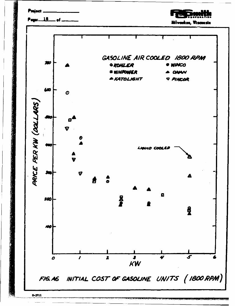
c. Costs
Figure A6 presents cost data on 1800 rpm unitsand Fig. A7 presents cost data on 3600 rpm units.The lower cost for 3600 rpm units is largely dueto the fact that many 1800 rpm units contain a3600 rpm engine operated at less than rated speedand load. However, the effects of wear due tohigher speed make an 1800 rpm engine more suit-able for shelter application. The two figuresagain indicate (as in the case of Diesel units)that utilization of a 4 or 5 KW machine gives alower first cost than two units of one half thepower output.
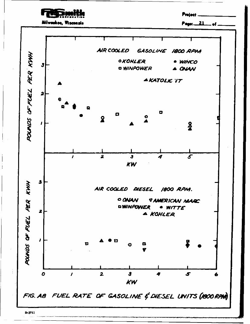
The fuel rate of between one and two poundsper KW-hour is shown in Figs. A? and A8.The fuel rate is improved considerably as therating of the unit is increased, but the trendis much less pronounced in the three to fiveKW range. Figure AS also reconfirms theprevious statement tktt Diesel engines aremore efficient than spark-ignition engines in thesesmaller sizes.
D,,fli
GA,5O-I../AE AIR COOLED 180 RPM
£ *W/ACto
4W- A
AA L
P16 A6 INMI.h4 COST ac&4SOUNE UNAITS (/8cW',PAf)

• | |IP&a A TPOoft
MIhIw koe, Vihosmi, Psgs:--h o.
I I "|
AIR CM£0 EJAW RA
a awA
S~mR o ,t oo RMO
'4%
0 0
KWINCNIR CO "~D %MO #?**A
0 0 WIA"
0 x
V A
Kw
FIG. A 7 INITI/AL COS •' r MEL RTE OF MSOLME A .wVE(3oD.1)-:711

POW. 20 of NIJW ý64, 0 lse fl
d. Operating characteristics
Engine-generator sets must be exercised duringthe 10-year stand-by period unless future
research results in more acceptable storagetechniques. The generally recommendedpractice is to exercise weekly for one-halfhour under part load. There was unanimousagreement in discussions with various enginemanufacturers that the length of the exercising
period should be one-half hour in order to in-
sure that the engine is thoroughly warm-cd up.
This prevents subsequent condensation whichcould result in corrosion. One or two manu-facturers suggested longer time periodsbetween exercising, but the weekly period was
generally considered best from the standpoint
of engine starting. However, carbon depositsin the cylinder caused b, frequent light-loadoperation would be lessened and thus the chance
of engine malfunction reduced if exercisingwere less frequent. If the engine is properly
exercised, the carbon build-up factor would not
be a valid consideration for less frequentexercising. in view of the accepted procedureof weekly exercising, which has been proven in
practice, and lack of data on how effectively
less frequent exercising would control carbon
deposits for 10 years, weekly exercising underpart load is recommended.
The sturdy, heavy-duty engines allow weekly
exercising. The LPG-fueled engines should
be exercised at 50 per cent rated load andgasoline-fueled engines should be exercisedat 90 per cent of rated load since LP_0G is acleaner burning fuel.
It is recommended that engines be operated at
80 per cent of rated load during the three week
emergency period. Three reasons for thisrecommendation are as follows:
(1) The reserve capacity will provide a safety
factor to allow for additional load and reduce thelikelihood of engine failure
Mllwukoe, Wims~a~m POW...21 &f-
AIR C00LED GASOL WA'~ /"0 RA~4#
0 WIAIPOWER A GOS4.4
AA IAKATLrC 'I
A
2 0AA
423 4
/(W
AIR C004EA 'E-SEL/90P.
0SON" VMIERICANA? MAC
0 WINPOWEA 0 WrrTTAA K0Htes
I4j
A 00
PF1G. AB8 UlEl- RA7E* Or G4ASOIL Ift ' DIESEL. IAV/735 (MO RAW)

Psiect mu '
(2) The lower bearing pressures, loweroperating temperature, and other factorts willincrease life expectancy of the engine.
(3) Carbon-deposit build-up in three weeks ofcontinuous operation should not be significantly
different at 80 per cent load than that expectedat full load.
e. Fuel
Possible fuels for reciprocating, spark-ignitionengines are natural gas, gasoline, LP gas, andproducer gas generated from solid carbon fuels.Natural gas is predominately -netl-ine end thuswould be stored as a gas unless cryogenicrefrigeration equipment was utilized. Thisrequirement is due to the fact that the criticaltemperature (above which liquefaction isimpossible at any pressure) is - 116 0 F formethane. Since high-pressure vessels andrefrigeration equipment are expensive, naturalgas is •iftiminated from consideration.
Gasoline is the most common of the spark-ignition-engine fuels and is a mixture ofhydrocarbons. The composition is variedseasonally to compromise between the ease ofstarting the engine and hot operating character-istics such as vapor-lock and fuel loss byevaporation.
Rather than specifying a certain analysis,gasoline is more often analyzed on the basisof the amount of the various fractions that dis-till at various temperatures. A typical U. S.Government specification requires less than 0. 1per cent surfur and the following per-cent-distillation- temperature relationshipV
Minimum per centdistilled
Temperature (F) (including losses)
167 10284 50392 90
III ~ ~~~ .II.I..IIi.I.I..

Mlwlr•awkoo, Wl~lsm~ss pegsL _ of -
The maximum residual should be two per cent.
An average composition would be 83. 5 to85 per cent carbon, IS. 0 to 15.8 per centhydrogen, and 0 to I per cent nitrogen andsulfur. Its heating value is about Z). 000 Btu/Ib.The specific gravity is from 0.7 to 0. 75.
Gasoline is more flammable than fuel oil, andconsequently it is more of a fire hazard. Whilea gasoline engine has a slightly better enginestarting characteristic than a Diesel engine atroom temperature, it has distinctly betterstarting characteristics at less than 32 0 F. Theassumed initial shelter Zeiaiperature (45OF) isin an indeterminate region and small Dieselengines may require ether capsules or otherstarting means, while the spark-ignition engineshould start without such aids.
LP gas is essentially liquified propane andbutane. It has a heating value of approximately?!, 000 Btu/Ib and a specific gravity of 0. 54(reference AZ). It is stored as a liquid andvaporized for use.
Producer gas is formed just prior to utilizationfrom solid fuels by burning the material in onlylimited oxygen to produce a gas consistingessentially of carbon monoxide, hydrogen, andnitrogen. The heating value per cubic foot islower than LPG and modification of the engineis necessary in order to obtain the same output.This does offer an opportunity to utilize easilystored solid fuels for use with an internal-combustion engine.
3. Gas Turbines
a. Availability
Gas turbines in the 30 horsepower and largersizes are in operation. Various large units havebeen installed and are functioning satisfactorily
D.271

rpaw 24 9f*1w ml....i
for commercial and industrial purposes. How-ever, no turbine-driven generators hatre beenbuilt in the range that even approach the fiveKVA maximum power output of this study.
b. Operating characteristics
Thermodynamic analysis of these units showsthat ao the size of the unit is decreased, thewheel speed of the turbine must increase to
maintain a practical efficiency. The limita-tions of the strength of materials and highfluid friction prohibit considering these unitsfor the five KVA power supply in the shelterapplication.
c. Fuel
These units use the same fuel as the Dieselengine.
B. Storage of Internal-Combustion Engines
The storage procedures for internal-combustion enginesare divided into three categories for the purposes ofthis discussion: (1) shelf storage, (Z) "moth-ball" storage,and (3) exercising. These three types of storage aredefined as follows:
1. Shelf storage is storage of the set as a unit at anengine distributor's warehouse, storage in thestock room of a manufacturer, or delivery to ashelter and storage in the original carton.
2. Moth-ball storage is the type of storage that onemight expect in "moth-balling" of used militaryequipment for future use and often involves dis-assembly and special preservation of subcom-ponents.
3. "Exercising" is a procedure whereby the engine isinstalled and made ready for operation. The engineis then operated periodically over the time intervalthat it is to be "stored".
3.-?I!
MI1WOU60. WIICau! Po ZS of
The last of these methods was unanimously recommendedby all engine and engine-generator-set manufacturersthat were contacted. There are valid reasons for this;a detailed discussion of each of the procedures follows:
1. Shelf Storage
The storage of engines in their original crating and/orcarton is feagible for several years under fairly goodstorage conditions (primarily elimination of moisture).However, even under the best storage conditions itis questionable whether or not the unit would functionsatisfactorily without maintenance before use after10 years storage. It is expected that in many instal-lations the unit would not function due to oxidation andcorrosion. The ability of the engine to function aftera ten-year shelf life could be checked by control testsand a statistical evaluation of results, but one draw-back discredits this means of storage and renders thetest unnecessary. The drawback is that the engine isfirst installed and utilized at the time of the emergency.First runs on new installations have a high probabilityof requiring at least minor adjustments on the powersupply system that cannot be corrected withoutexperienced personnel and the proper equipment.
The following precautions should be considered inattempts to provide satisfactory shelf storage:
a. The final engine "break-in" would be with an oilcontaining a vapor-phase inhibitor to protect themterior surfaces from corrosion.
b. The engine-generator set would be wrapped orsealed in a moisture-barrier material in such amanner that the barrier would not be damaged orbroken in handling during shipment.
A crate protecting a carton, with instructions torefuse to accept any crates containing damagedcartons, is one method of guarding against adamaged moisture barrier. The purchase orderfor the engine-generator set would include per-mission to refuse acceptance of units receivedwith damaged cartons.
. .-2711

Pup: 26 of - lk
c. A container of desiccant would be placed withinthe carton to absorb moisture. An availablematerial that changes color when saturatedcould be placed near a cellophane window in themoisture barrier. If the color change indicatedsaturation, the desiccant would be replaced.
It is anticipated that the above procedure would resultin formation of a thin film of copper oxide on thegenerator collector rings, but this could be removedby holding a low-cost seater stone against the ringsfor a few revolutions of the generator shaft. Includingthese stones in the engine-generator-set shipmenthas been used in the past and the procedure is effective.The magneto points might have to be cleaned with emerycloth.
While there is insufficient data to show whether ornot a vapor phase inhibitor would protect the cylinderof the engine for 10 years, additional research is notsuggested for this untried method to guarantee 10-yearstorage. Again the main disadvantage of such astorage procedure is that the engine-generator setcannot be tested after installation to insure that theover-all power-generation system is functioningsatisfactorily. Unsatisfactory industrial experiencewith starting equipment for the first time providessufficient reason to eliminate this method as astorage procedure.
2. Moth-balling
Moth-balling is a procedure in which the equipmentwould be installed and tested under actual operatingconditions and then would be partially disassembledand repackaged for optimum shelf life. This procedurewould eliminate the "first starting" objection of theshelf-storage method. The success of a Dioth-ballingprocedure would depend upon the ability of the instal-lation personnel to moth-ball the equipment and theshelter personnel to put the equipment back intooperation. Trained personnel with the proper toolscould assemble an enginee-generator set from individualcomponents that had been individually packaged to pro-tect all unpainted surfaces from corrosion.
D-uII

Mi•wms Vlms Psgrn O• ......
A suggested moth-balling procedure wotrd be that thegenerator be packaged as a unit and, fo:" the bestprotection against the ten-year- storage effects, theengine be as least partially disassembled for applyingand removing protective coating from the pistons,cylinders, and other unpainted surfaces. The car-buretor and the magneto could be stored as sub-assemblies, provided they were removable. Retentionof residual magnetism is discussed later. The storageof the generator (except for demagnetization) is not aproblem, and engines have been rejuvenated after 10year storage by experienced personnel.
There are possible schemes for moth-balling thatwould require less experienced personnel. Thesemethods include such procedures as hermeticallysealing the unit in a well-constructed, inert-gas-filledchamber, but some mechanical ability would still berequired on the part of shelter personnel to connectthe fuel line, exhaust pipe, etc. A stripped thread,broken bolt, kinked fuel line, or other damage due tonervous, unskilled personnel might render the unitunusable. In addition to moth-balling of the engine-generator set, the other equipment in the powersystem would have to be moth-balled. This additionalmoth-balling would not have to be technologically ascomplicated as for the engine-generator sets, butfactors such as keeping insects out of motors andmildew off equipment would have to be considered.
The main objection to moth-balling procedures is thatunless skilled personnel are available during theemergency, current moth-balling procedures wouldhave to be revised to simplify restoring the equipmentto active duty. These novel modifications have notbeen tried nor proven by field experience.
3. Exercising
Exercising is a procedure by which the engine isoperated under partial load for a short period (onehalf hour for this application) and placed on stand-byduty -without operation for a period of time (a weekis recommended for this application). This practice
I"lft11

PoMwumko, *lsmmsla
is commonly followed for keeping engine-generatorsets in good operating condition and was recommendedby all engine and engine-generator-set manufacturersinterviewed. The advantages of this practice are:
a. The set is tested on location by qualified tech-nicians to insure that the power system isfunctioning satisfactorily.
b. The weekly operation of the equipment is apositive test that the set is ready to operatewhen needed.
c. Operation of the set removes the cop-per-oxidefilm on the collector rings of the generator andthereby eliminates the need for cleaning of thesecomponents %ihen the emergency occurs.
d. The cylinder walls are repeatedly covered by anew film of oil to prevent corrosion.
e. The pole laminations (if not permanent magnets)would be remagnetized weekly to insure that theywould not lose their residual magnetism. If thepoles lost residual magnetism, the magneto andgenerator would not function.
f. The use of soft-iron electromagnets wouldeliminate the need for permanent magnets. Somemanufacturers believed that permanent magnetswould remain at full magnetic strength for 10years, but factual data are missing. Permanentmagnets without a satisfactory "keeper", suchas is the case of some magnets when installed ina generator, demagnetize with time. Generatoroperation also tends to demagnetize permanentmagnets.
The disadvantages of exercising are:
a. The weekly exercising requires fuel. In 10 yearsthe engine-generator set would run 260 hours ascompared with the required 504 hours operatinglife for a continuous three week period of operation.
m~mm 7

Aldwaukse WISCMuIN PO 2 of -
The fuel requirement for the entire exercisingperiod may be computed from data presentedin Fig. A3. TL- requirement varies from 80 to46 gallons per KW rating for the 0. S KW and5 KW machine respectively when gasoline is usedfor fuel. Although the exercising load is similar,the fuel requirement for a Diesel engine will belower than for a gasoline engine. The LPG require-ments (one half load operation) are approximately60 gallons per KW rating for either a I KW or5 KW unit.
b. Some form of periodic inspection during the 10year stand-by period would be required. Thefrequency and extent of the inspection would bedetermined by the degree of automation of thesystem.
The disadvantage of reduction in engine life is partiallyoff-set by the fact that the heavy-duty engines have alife expectancy of 1000 to Z000 hours of continuousoperation. The life for intermittent operation will beshorter due to the greater wear rates during coldstarts. Available data strongly indicate that anaccelerated life test for engine evaluation could bedeveloped to evaluate whether or not the shelter appli-cation requirements of an engine-generator set are met.This test consists essentially of reducing the timebetween exercising to about eight hours. The failureof a properly exercised engine would more likely bedue to wear than to corrosion. This wear could beevaluated at an accelerated rate as long as the timeinterval between operating periods allows thoroughcooling of the engine.
The equipment for automated exercising is discussedbelow. The engine rnu•t be started, have a loadapplied, have the load removed, and then stopped.Various combinations of exercising equipment that couldbe used in a shelter become apparent from a descriptionof the equipment.
a. Running-time meter - A timing clock records thetotal time an engine has operated. This serves
!)-2711

as an indication of how frequently the engineoperated and also shows when an oil change isnecessary. This clock costs less than $30. 00.One source of such a clock is the Onan Divisionof Studebaker Packard Corp., Minneapolis, Minn.
b. Exerciser Time Clock, a one-half-hour timer,automatically shuts down the equipment andeliminates the need for personnel to wait forone-half hour before stopping the equipment.The timer cost would be less than $35. 00. Asource of such a timer is Onan.
c. An Automatic Starter. - This would electricallystart and stop the engine-generator set. Anautomatic starter would cost less than $110. 00.One source is Katolight Corp., Mankato, Minn.
d. Sequencing Control - This control, which couldbe used for the emergency period as well asduring the exercising period, would automaticallyapply a load to the equipment in such a mannerthat the engine generator set would not be over-loaded by motor starting. A factor to considerin deciding whether or not to utilize this equip-ment is that the larger motors may supply torqueto their loads through a clutch. This clutchwould also have to be automatic if these motorswere part of the exercising load. The cost of asequencing control varies with the size of theset. A control for a 4 KW set costs $265. 00;one source is Wincharger Corp., subsidiary ofZenith Radio Corp., Sioux City, Iowa.
The listed automatic equipment could be replaced bythe following manual operations and/or simplifiedequipment:
a. Personnel could record the running time of theequipment and stop the equipment at the end ofthe exercising period. This would eliminatethe need for the exerciser-time clock andrunning-time meter.
MI III IIM -

PIwemke. O Wisome POW.....f -
b. A starting rope could be used to start the engineinstead of the automatic starter.
c. A series of switches could be turned on in theproper sequence instead of using a sequencingcontrol.
The exercising procedure appears the most reliable,has the most field-operation background (for example,most automobile engines are operated for 10 yearswith intermittent duty), and is used and recommendedby all of the engine and engine-generator-set manu-facturers who were interviewed. Therefore, this isthe recommended "storage" procedure for the shelterapplication.
C. Storage of Fuel for IC Engines
The successful storage of fuel (gasoline, liquified petroleumgas, or fuel oil) for the ten years required by the shelterapplication is a matter of speculation rather than fact.Conclusive data proving that these fuels can be successfullystored for 10 years is not avuilable because the need forthis long-storage characteristic has not been experiencedin the past. Isolated cases of fuel having been stored forcertain periods prior to use have been recorded, but theevidence is questionable. A more detailed study will soonbe published by the U. S. Bureau of Mines.
The shelter application requires continuous operation ofthese engines for several weeks. This is a differentsituation than using a small tank or two of aged gasolinein an engine. The effects of utilization of aged gasolineis an accumulative process. Gum deposits accumulateto the point where they clog the carburetion system. Theshort-time use or intermittent use of aged fuels does notprove that the same aged fuel could be used continuouslyfor several weeks.
Since factual data were missing, opinions were obtained.The opinions expressed below are on the basis that thereexists evidence to show that the fuel will store satis-factorily for at least the following indicated times.
I- I

POW • 32 f NOlW"4% lllSM81
Longer storage periods might be satisfactory, but this
would be speculation. These estimates are based on a
storage system that does not contain copper, or zinc
and the temperature is below 80 0 F. No other unusual
precautions are assumed.
1. Conventional gasoline from the local gas stationwill store for six months. This is standard practice
and not an estimate.
2. Conventional gasoline with special additives will
store for one year.
3. Regular straight-run, aviation-type gasolines will
store for one year.
4. Straight run gasolines with the addition of special
additivies will store for two to five years.
5. No. 2 fixel oil will store for one year.
6. No. I fuel oil will store for two years.
7. Liquified petroleum, fuel (L.P.G. ) will store for
five years.
8. Special additives plus very clean tanks might allow
No. I fuel oil to store for five years.
This information is the basis for the recommendationthat if there is insufficient time or funds available for
further research, the fuels mentioned in items 1, 3,
6, or 7 above be stored in quantities that are consistentwith the following procedure. The minimum quantity of
fuel stored should bp consistent with one-half-hour-weekly exercising for the above estimated storage life
plus the operation during the period of utilization. The
entire fuel supply should be replaced at the end of the
recommended storage life. Table AZ presents the
required fuel rates for typical engine-generator sets
considered in this study.(A3).
M90I TM M

ONlwuuk.., Wiaesin POf 3_3 _f
The use of a gas producer to generate producer gas iswell known and has been used extensively on cars inEurope and Japan. The principle, incomplete oxidationof a solid fuel, c,',d be accomplished by means ofequiptzient for fuel storage and combustion presentedlater in this report for the Rankine-cycle turbine-alternator unit.
The anticipated efficiency of producer gas generation is50 per cent. Final design of the unit and possible dif-ficulties in use would have to be evaluated by experi-mentation. It would be an inconvenient means of providingfuel for weekly exercising.
Finally, it should be mentioned that LPG has a storageproblem peculiar to itself in that provision must bemade to vaporize the fuel prior to utilization. Thismay be accomplished by (1) flow of heat from earth toa buried tank, (2) flow of heat by convection iromsurrounding air to a tank in a fuel room, or (3) evapora-tion of the liquid prior to utilization in the engine by anexhaust heater or an engine-coolant heater. Recommenda-tion for proper installation of LPG equipment is availablefrom engine-generator set manufacturers and is discussedin detail in reference A4.
D. Heat Removal from IC Engines
1. Total Heat Rejection Requirements
The total required heat rejection rate, Hr (Btu/hr/KWrating), for continued operation of an internal-combustionengine can be computed from the specific fuel rate, FR(lb/kw-hr), and the heating value of the fuel, HV (Btu/Ib).Since one kw-hr equals 3413 Btu, the total heat rejectionrate would be
Hr = FR(HV) - 3413 Al)
2. Heat Rejection to Various Heat Sinks
This rejected heat would leave the engine-generatorset as (a) heat content of the exhaust gases, (b) heatdissipated by the generator, and (c) heat dissipated bythe engine. The quantities of heat dissipated by thesevarious means may be determined.
D-rII
pMm-Fewo 34 of .o, iam aNla
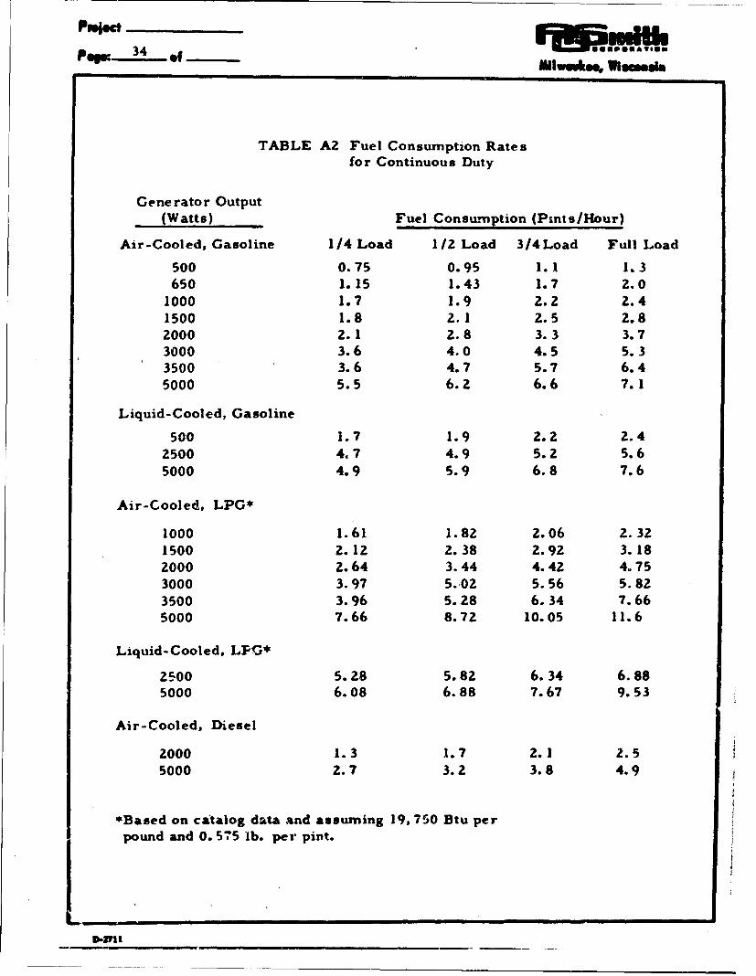
TABLE A2 Fuel Consumption Ratesfor Continuous Duty
Generator Output
( (Watts) Fuel Consumption (Pints/Hour)
Air-Cooled, Gasoline 1/4 Load 1/2 Load 3/4Load Full Load
500 0.75 0.95 1.1 1.3650 1.15 1.43 1.7 2.0
1000 1.7 1.9 2.2 2.41500 1.8 2.1 2.5 2.82000 2.1 2.8 3.3 3.73000 3.6 4.0 4.5 5.33500 3.6 4.7 5.7 6.45000 5.5 6.2 6.6 7.1
Liquid-Cooled, Gasoline
500 1.7 1.9 2.2 2.42500 4.7 4.9 5.2 5.65000 4.9 5.9 6.8 7.6
Air-Cooled, LPG*
1000 1.61 1.82 2.06 2.321500 2.12 2.38 2.92 3.182000 2.64 3.44 4.42 4.753000 3.97 5.02 5.56 5.823500 3.96 5.28 6.34 7.665000 7.66 8.72 10.05 11.6
Liquid-Cooled, LPIG*
2500 5.28 5.82 6.34 6.885000 6.08 6.88 7.67 9.53
Air-Cooled, Diesel
2000 1.3 1.7 2.1 2.55000 2.7 3.2 3.8 4.9
*Based on catalog data and assuming 19,750 Btu perpound and 0. 575 lb. per pint.
DIII _ __ __1_ _ _

WIwouk, WIssusi, Pewe 35 e9-f
a. Heat removed by exhaust gases
This quantity can be computed approximatelyby the following formula (assuming the air entersat 90°F and the exhaust gas leaves at 1600 0 F):.
Hre = MaCa (1600 - 90) A2)
where Hre is the heat removal rate by theexhaust gase-s (BttI/hr/KW rating)
Ma is the combustion air flow rate (lb/hr/KW rating)
Ca is the specific heat at constant pressure forair (0. 24 Btu/Ib F)
All of the heat in the exhaust gas is not ejected bymass flow from the shelter because the exhaustgases heat the exhaust pipe, which in turn heatsthe surrounding air. Thii may be minimuzed bymaking a short exhaust connection from the engineto the outside of the shelter and insulating theexhaust pipe.
b. Heat dissipated by the generator
Since the rating of a generator is the output, Wo,(KW) which is generated at some efficiency,e (per cent), the generator heat that must berejected, Hrg (Btu/hr/KW rating), can bedetermined quite readily. For a machine with anyKW rating this becomes simply
Hrg = 3413 (100 - e)/e A3)
If more specific information is not available, agenerator efficiency of 70 per cent is reasonablein the less-than-S-KVA machines.
c. Heat dissipated by the engine
The heat dissipated to the engine room and tothe engine cooling water (if water cooled) isgiven by Eqs. Al, AZ, and A3 as
Hrc = Hr - Hre -Hrg A4)
D-VI!

POW 36 .f ie•u oolueu
where Hrc is the heat removea from the engineby air or water cooling along with miscellaneousradiant and convective heat loss to tale engineroom, (Btu/hr/KW rating).
3. Sample Calculation
Assume that a 4 KW engine-generator set is using60 lb of air per hr and uses 20, 000 Btu/lb fuel at aspecific fuel rate of 1 lb/kw-hr; the generatorefficiency is 70 per cent. The following heat re-jection rates may be easily computed.
Total heat rate : 4 m.0) (20,000)- 3413366, 348 Btu/hr
Exhaust-gas loss = 60 (0.24) (1510)= 21,760 Btu/hr
Generator loss = 4 (3413) (100 - 70) /70= 5851 Btu/hr
Engine cooling loss = 66, 348 - 21,760 - 5,851= 38,737 Btu/hr
When it is remembered that an average active adultdissipates only 600 Btu/hr, this simple example in-dicates that the cooling problems with even smallengine-generator sets are important.
4. General Discussion of Heat Dissipation
a. Generator heat dissipation
While the actual rate of heat dissipation for anygenerator is given by Eq. A3, the generatorefficiency will usually be between 65 and 75 percent. Hence, it will be sufficiently accurate toassume that the generator efficiency is 70 per cent;this makes Hrg equal to 1463 Btu/hr/KW ratingfor all cases. The significant factor connectedwith this heat loss is that the generator windingsmust not be allowed to exceed 176 0 F unless
L.73
---------------------------

Mllwakh . Wissmsim POW -L 3 -f
special insulation allows higher temperatureoperation. Thus the required mass flow rateof cooling air, Mc (lb/hr/KW rating), is
Srelated to the inlet air temperatures Ti, and thepermissible outlet temperature, TO. Usingthe First Law of Thermodynamics (conservationof energy) and tacitly invoking the Second Lawof Thermodynamics (Tb must be less than176 0 F), the value of Mc becomes
Mc =Hrg/Ca(To - T') 61004To - Ti) AS)
Using Newton's Law of Cooling, a relationshipbetween an over-all heat transfer coefficient, U(Btu/hr sq ft F), and a mean temperature dif-ference between the generator surface and thecooling air, dT, is given as follows:
WoHrg = UAAT Btu/hr A6)
where Wo is again the KW rating of thegenerator.
Manufacturers of small engine-generator setsusually give total air flow requirements for coolingthe generator and the engine.
b. Engine heat dissipation by means of a radiator
If the engine is water cooled, the coolant shouldnot enter the engine at a temperature of less than140OF (A4). The trend of wear rates versus timeafter starting were recently reported (AS) and theresults are shown in Fig. A9. These data showrapid wear rates shortly after starting the engine;this may be due in part to a cold engine (data*were reproducible only with the engine thoroughlycooled) and in part due to the drainage of lubricatingoil from the cylinder surfaces. This figure indicatesthat an accelerated-life-testing program may bepossible if the most important factor in exercisingis cylinder wear and not corrosion. The weekly one-half-hour exercising of a cold engine is definitelya severe requirement for long engine life.
D-27l1

lo*
Sr4r^
PIG4. A 9 WEAR CNARAC TEPIS 711S OFCASOL/A/C ENGINES

il • m ae l • ~~P OW 39 , • ...
The water should not leave the engine blockabove 180 0 F, for higher temperatures mightresult in local boiling within the engine. Thisboiling could cause scale deposits, which wouldimpair the heat transfer and could result inlocal hot spots. Scale deposits could possibly clogwater passages. If the engine is air cooled, theheat dissipation fins are probably around 375°Fon the surface. Therefore, it can be reasonedthat the boiling point of the coolant, not the enginecharacteristics, limit the water temperature.
Permanent antifreezes (ethylene glycol) have ahigh boiling point (387. 5F); but this direction(toward higher temperatures) is not a logicalmanner in which to proceed. Higher radiatortemperatures cause the engine exterior to behotter; this means more beat is transferred tothe engine environment inside the shelter.
Air-cooled engines require large volumes ofair to flow across the engine. The requiredrate varies nearly linearly with KW rating; a5 KW unit requires approximately 700 CFM ofatmospheric air. Outside surfaces of air-cooledengines must run hotter than is necessary forliquid-cooled engines because the poor heattransfer characteristics of air require a largertemperature difference.
d. Combined generator and engine heat dissipation
The generator and the engine can be cooled byusing the same coolant in a series flowarrangement, provided that the temperaturerestrictions on the generator are satisfied.The heat transfer equations will usually besatisfied by combining these components forheat transfer calculatione, but the operatingtemperature of the generator coolant should bechecked to insure that the generator does notrun too hot. Cooling air is normally passed overand through the generator and then over the engine
IiD-YJII

P 40 of
to insure generator cooling and taking advantage
of the high temperature finned surfaces on theengine to discharge the air at a higher temperature.
S. General Cooling Requirements
Regardless of the type of cooling system,certain requirements must be met as shown inFig. AlO. All heat removal means shown inthe figure were previously described, but it willbe convenient to consider the component of Hrcthat is dissipated only to the engine room sur-roundings by convection and radiation. Let thiscomponent be represented by HE (Btu/hr/KW rating).An estimate of the minimum heat loss from theengine to the shelter by this means will beinvestigated.
If the engine is a I ft by I ft by 2 ft rectangularparallelepiped (a minimum surface area), itwould have an exposed surface area of 8 sq ft
assuming that it is in contact with the floor onone surface. The surface coefficient of combinedheat transfer, hc, would be at least 4 Btu/hr sq ft F,and the average surface temperature (due to the140OF minimum coolant restriction) would be atleast 180°F. If the engine room environment is
assumed to be not warmer than 110°F, thenNewton's Law of cooling yields
HE = hA&T = 4 (8) (180-I10) A7)= 2240 Btu/hr
The mass flow rate of available 900F air, Mae(lb/hr), required to remove this heat if a tempera-ture rise of 200F is permissible would be given as
Mae = 2240/(0.24) (20) = 467 lb/hr AS)
or 104 CV4. If the allowable temperature riseof the air must be reduced, the air flow raterequired must be increased. It must also beremembered that the generator losses are trans-ferred by cooling air.
94M

C004.ANr (uMTrAQ 4Q £XAW4ur ~44U c~awAovrr mir"A1IR) AT7 JS*F-O rA~Ae) Ar 7'c /-0'
__ L
cootA~wr (mazi oe CO.4masTI ON COOLAwr (WITERAIR) Ar- 7-9114V'0. Ahe PWI O AIR) AT 7 100.c
E/CG. A 10 C004 1"fG ,QE(.U/REMEA17TJ FqZAAG/NE c-ENERAroR wE7.-5
wVII Fm&T*I M-p RM -w T4 RPINMIW M

raw 42 e iwuul f, rwmmuim
The conclusion arrived at from this analysis isthat the engine-generator set should be isolatedfrom the engine room. Methods must be- developedto remove the engine and generator heat losses bysome means other than using copious supplies offiltered shelter air.
6. Methods for Coo!ing the Engine-Generator Set
Several methods of engine and generator cooling aswell as noxious gas control are presented to
demonstrate use of comnmercially available equip-ment. A "wind tunnel" arrangement is used in mostcases to give the shelter designer an opportunity topurge any noxious gases fronm the engine with aminimum amount of air. If sufficient shelter air isexhausted directly into the engine room to cool thegenerator, remove engine radiation losses, andcontrol noxious gas concentration, the "wind tunnel"concept would become unnecessary. Also a copioussupply of exhausted shelter air would eliminate theneed for a radiator to cool generator cooling airwhen well water is being used to cool the engine.
a. Well water cooling
Figure All is an arrangement whereby waterfrom a well or other convenient source iscirculated through a .adiator equipped with athermostatically controlled valve, which iscontrolled by the temperature of the water inthe mixing tank. When the water in the mixingtank rises above 160 0 F, the thermostaticallycontrolled valve opens and allows cooler waterfrom the radiator to flow into the mixing tank.When the temperature of the water in the tank
has dropped to no lower than 140OF as a minimum,this valve closes and stops the flow of the wellwater. The water in the mixing tank (at atemperature between 140-160 0 F) is pumped tothe engine and in this manner cools the engine.The mixing tank is equipped with an overflowpipe which provides an outlet for excess waterwhich can be used for waste heat applications orbe discharged.
PrPr ýIp

Mhiwuuhs, m..t". p.....i43 of-
AIR
C/A'C414/A7YOA'
WA7rE* FMt2
R AA
rl
7
~ RPLOW
1V4TL. D
~vt3

pFw 44 of _
Excess air from the shelter is utilized in thisarrangement to cool the engine-generator setand to provide combustion air. Some of the airis exhausted from the shelter and thus helps toremove noxious gases; the rest of the air that isnot used by the engine for combustion is recir-culated in the erclosure and acts as a circulatedfluid for cooling the engine-generator set. Heatis removed from the air as it passes over thewater-cooled radiator.
b. Contaminated- air direct cooling
The cooling of engine-generator sets in environ-ments of contaminatcd air, where a supply ofliquid coolants may not be available, suggestsusing the contaminated air for direct coolingwith a suitable means for decontamination forservicing requirements. The' reasons for thisarrangement are:
(1) Although the engine can be liquid zooled byconventional procedures that allow the engineto be located below ground and its radiatorto be located above ground, the generator isalways air-cooled. This air-cooled generatoris satisfactory for common usage of engine-generator sets, but using shelter air forcooling would give rise to a heat-dissipation-from-the-air problem or the need for largequantities of filtered cooling air.
Small generators are from 65 to 75 per centefficient--thus every three kilowatts ofelectric power produced is accompanied by theliberation of a kilowatt of heat at the generator.As mentioned above, the required mass flowrate of air to reject heat from the generator
alone is large and it is undesirable to reject alarge percentage of the engine-generator heatusing filtered air from the shelter.
~~bm

Whwuu~ii, Wiseusesh.~S
(2) An objective is to prevent as far as possibleany contamination of exposed engine and gen-erator parts and thus minimize decontaminationneeds. In those areas where radiation fromfallout would be acutely hazardous, particlesizes would be relatively large (greater than40 microns). Hence the use of gravity separationand simple filters prior to the generator setcould minimize contamination that must beeliminated in order to repair equipment.
(3) Many air-cooled engines, particularily thosedesigned for outdoor utilization, could bewashed down by a water spray without illeffects. Outdoor wiring is common, andwelding generator sets for outdoor constructionare common.
(4) Although the engine could use outside air forcombustion, except for supercharging withmomentary blast overpressures and heatingintake air by nearby fires, it would be prefer-able to use purified shelter air and therebyrestrict contamination to external parts. Alsothe combustion air requirement is quite smallcompared to cooling air needs.
(5) Considering the light weight fin and tube con-struction of radiators and the rugged finconstruction of air-cooled engines, the entireair-cooled engine would be more resistant toa blast than the radiator of a liquid-cooledengine.
(6) In the opinion of many engine-generator setmanufacturers and personnel associated withnuclear reactors, utilization of contaminatedcooling air should not affect the engine-gener-ator set operation.
In addition to the advantages of maintenance andheat dissipation from the generator mentionedabove, the following advantages could be obtainedfrom using the contaminated air for direct coolingthe engine-generator set and for other purposes.
II IIIIIIIKI•IIIII III I

PW 46
(1) The fuel supply could be isolated fromthe shelter proper. Liquefiid petroleum
gas could be nore readily used as a fue'
without danger of contaminating the shelterair.
(2) The noise and odor accompanying engine-generator set operation would be isolatedfrom the shelter proper.
(3) During the ten year standby period, theengine-generator set in the relatively smallcontaminated-air duct could be kept dry bya few strategically placed light bulbs toheat the surroundings and thereby cause anywater to remain in the gaseous state; free
circulation of air would remove the watervapor before water concentrations in the airwould be such that condensation would occur.
(4) Lower cost air-cooled engine-generator setscould be utilized instead of the more expensiveliquid-cooled systems. There are maviy moreof these small size (5 KW and lower) units onthe market than small size liquid-cooled units.
A suggested arrangement of a means for utilizingcontaminated air for direct cooling an engine-generator set and providing combustion air for awater heater burner is shown in Fig. A12.
Contaminated air enters the engine compartmentthrough a hooded duct (possibly equipped with alow cost dust filter), passes over the engine-generator set, is used in part for combustion inthe burners and is rejected to the atmosphere.
In the event that service on the engine-generatorset is required, two drop doors are closed oneither side of the engine-generator set (purgingof poisonous gas follows closure of one door)and the entire chamber and equipment between thedoors is washed down by steam or water sprays.
I Il II 1I

IIN
D-371JLJ4M

laý@ am S A VI94 ,Pe _e: 48 o__f Milwouk., Wisconsin
The radioactive liquid is collected in a sump forpurification or discharge. The burners couldcontinue to operate by using shelter air duringthe maintenance period.
After the necessary servicing has been done on theengine-generator set, the drop doors are rzisedand the engine is restarted. The oil should not beseriously contaminated since, as the figure shows,
the crankcase is vented to the carburetor andshelter air is used for combustion.
The fact that radioactive dust concentration is apersonnel hazard suggests that preventive measuresshould be taken to minimize the contamination that
reaches the decontamination chamber. Of course,the passage is fitted with suitable covers and
shields to prevent direct radiation fromcausing the ch;;-n.b-r itself tc become radio-acn"--: t.hi d:zign shou!d mirimimze the amount
of radioactive dust that enters the chamber. Thiscan be accomplished by a low-pressure-drop airfilter in the contaminated air inlet duct. Theengine blower characteristics (or auxiliary blowercharacteristics, if used) could be matched with thefilter characteristics to permit the necessary air-cooling of the engine-generator set.
The filter could be positioned by remote controlbefore starting the engine-generator set (presuminga blast had destroyed the outside electrical sourceand outside air was contaminated). Other possibleplans would reinforce the filter supports or providemeans for replacing filters by remote control.
A thethod for prevention of excessive contaminationwould be to vent the engine crankcase to the
carburetor and use decontaminated air from theshelter for the engine combustion process. Theuse of shelter air for combustion would protect the
interior of the engine from contamination and wouldeliminate the need for handling any surface notwashed by the decontamination spray. The proba-bility of a generator maintenance problem is verylow.
I lI I I I II I I I I I I l I II I II

it•ProjectMilwouk.., Wisconsin Page: 49 of
An inventory of spare - -rts for the generator isprobably not required, A sealed generator wouldbe ideal but contamination of generator internalsis no part_4cular hazard because of their high degreeof reliability.
c. Recirculated-water cooling
Figure A13 is much the same, in some respects,aa Figure All. Air from the shelter enters theengine compartment where portions are used forcombustion, for discharging noxious fumes andfor recirculating to cool the engine and generator.
The generatir is further cooled by water-filledcoils which are wound around the generatorhousing. After passing through the coils on thegenerator, the water is pumped through aradiator and up to a cooling coil located in a ductwith flowing contaminated outside air. In this waythe heat which was transferred to the water fromthe generator and from the radiator is rejected tothe atmospheric hc-t mink. Many of the methodsfor reducing contamination of the d.rt are identicalto those mentioned above.
The engine block is primarily cooled by the waterpassing through it. Hot water (180 0 F) from theengine is pumped into a mixing tank where someheat is transferred to a heat exchanger; this cooierwater (140-160 0 F) is returned to the engine and thecycle is repeated. The heat exchanger systemmentioned above is equipped with a thermostaticallycontrolled pump (controlled by the temperature ofthe water in the mixing tank) which only operateswhen the water in the mixing tank rises above 160 0 F.
Since the arrangement in Fig. A13 contains twoseparate closed systems for rejecting heat to theoutside, some provision must be made to replenishany water that may be lost from the systems. Acylindrical container equipped with a funnel, pressuretight cap, and a hand-operated air pump can beused pneumatically to force water into the system
D -2 7T 1 T

Pegp: 50 M.6m* Wisconusi
COrA17AMI/Ae C. AIR
AIR REL IEF-
VAItVC
ECXHA 115'r
-AX ZI __C#
RAD/ATroR
FAc A 13 iAEC!RCVLA TED WA7,T124Q COL/A/t SYSTEM

1!t Prject
Milwaukee, Wisconsin Page:- 5 1.- of
while the air-bleed valves at the higz-est pointin the system are open. The air-eliminator tanks
are installed to remove residual air during thefilling operation and air released while heating
the water.
d. Evaporative ,:ooling
Figure A14 is essentially" ete same as
Fig. A13. The main difference is that in
Fig. A14 the rejection of heat is acccnmplishedthrough the evaporation of water as in a coolingtower. If the conrairer5 which collect the
water in the contaminated air stream, are ac:es-
sible for replenishing the suppl•• due to leaks
and evaporation, no other equipment is re-
quired. If these storage tanks are inaccessible-
a method similar to that used previously can
be employed to pump water into the p~pes.
E. Removal of Noxious Fumes from IC Engines
Internal combustion engines generate noxious fumes due
to the combustion prozess. Obnoxious fumes can be
generated from heating of the crankcase oil and evapora-
ting oil accidentally spilled on the exterior of the unit.
1. Exhaust Gas Removal
The combustion products need to be vented to the
outside atmosFpSere. Figure A15 is a diagrammatic
illustration showing a procedure for accomplishing
this exhaust gas removal.
The arrangement illustrated in Fig. AI5 is a
standard recommended by nearly all engine
manufacture rs.
A good exhaust system must be well supported
independently of the engine and connected to the
engine with a flexible metal connector made as a
continuous piece. It must be large enough in
diameter to reduce back pressure and arranged
so that water from rain and snow cannot enter.

5m2
+W k1rER - M4K'E UP0 A&+M
AIR 70
AWII
PcIG. A/ 1 £ VA POPA TI VW COOL INGC 6 YST7E- M

MI~uu..,W~esu~mPgs..JL ......-.
JM4OLS 70 WAMIr~ H~rAm~4msj-" Byca/v~r7&OV
ARWOV COAVRErZ
CONDENSAAOX ac, SO"1/ RMA c&ES
MU/~LERC4o%WoT rooVMW 7;V-A AEAt I/
cMXAN4SI 4044M/ U4Lw
F47G. A 45 E-XAA 41sr &A$ PEA4Oký4L SY.SrZi

pswi
POW. 54 of wm&.sr m...l
It must also be gas tight. Where a vertical exhauststick is necessary, as is assumed for a shelter, analternative to bending the exhaust pipe outside of theshelter is to put'chase commercially available raincaps for the enhaust staci's. Every provision mustbe made to mir~imize back pressure on an exhaustsystem. Snmaeof the adverse effects of excessiveback pressure are 1) loss of power, 2) poor fueleconomy, 3) high combustion temperatures result-ing in short service life, 4) jacket water overheating,and 5) crankcase sludking and corrosion or bearingdamage. In order to minimize back pressure,exhaust pipes should be as shoit and straight aspossible. Right angle bends should be kept to aminimum, and when used they must be of a radiud.....four or five times the diameter of the pipe.*
The muffler should be mounted as close as possibleto the engine to keep it from rusting out, but itshould never be directly connected to the exhaustmanifold; this practice would put excessive stresseson the manifold and could cause it to fail.
NFPA recommendations (A6) require exhaust pipeswhich pass through combustible roofs be guardedat the point of passage by ventilated metal thimbleswhich extend not less than nine inches below roofconstruction, and which are 12 inches larger indiameter than the pipe. Uf double ventilated metalthimbles are used, the same requirements applyexcept that the thimble should be at least six incheslarger in diameter than the pipe.
2. Obnoxious-Fumes Control
The lumes from the crankcase can be vented bypiping the breather vents of the crankcase to theair intake of the carburetor. These fumes are thenburned with tho fuel or pass out of the shelter throughthe exhaust pipe. This breather tube from the crank-case to the air intake is standard equipment on someengine-generator sets. U the air surrounding theengine is not isolated from the air in the room, the
I IIII IIm II I I4,Il

~Palo"
AIIwIoee,1,is . POW 5 Of -
breather tube should be considered an essentialcomponent of the engine generator set in order toprevent air contamination. It should be installedby the manufacturer because it is a modification tothe set.
The utilization of oil in an engine usually results inthe spilling of some oil on the set. This oil willevaporate or burn and contaminate the air surround-ing the set. This contaminated air is automaticallyisolated from the shelter in the heat-removal schemesshown in Figs. All - A14. HI'vever, if such schemesare not used, the engine generator set should belocated so that the air that has flowed past the engineis not mixed with the engine room air supply.
If the engine-generator set is to be used in a smiAenclosed chamber designed for preventing shelterair contamination, the heat dissipation requirementsof the generator must be considered. This willresult in an enclosure similar to those shown in theheat-dissipation methods in Figs. AlI - A13.
F. Control of Noise and Vibration From IC Engines
1. Mounting of Engine-Generator Sets
The mounting procedure for the Installation of anengine-generator set varies with each model and theexisting floor. The procedures for the various makesare recommended by the set manufacturer anddistributors who should have experience with theirparticular sets. These recommendations should beadhered to and the installed set should be testedbefore full payment is made.
The purpose of the special mounting procedure is toprevent distortion of the engine-generator set com-ponents during installation and, once installed, toallow flexibility so that the set can vibrate freely, thusensuring that vibration is not propagated through thesurrounding structure. Objectionable noise couldresult in addition to the stresses that would beinduced by vibration of the surrounding structure.
5.2711
A - -..

POW 56 'ofom
A brief description of mounting prcedures includedto familiarize the reader with the varioustechniques. follows:
a. Semi-portable (temporary) mounting.
Some engines, particularly in the smaller sizes,are mounted on skids or slide rails. The natureof these mounting devices allows the engine-generator set to be dragged over relativelysmooth surfaces without damage to the set. Skid-mounted engine-generator sets frequently requirevibration dampers between the set proper and theskid (Fig. A16). Fig. Al7 illustrates this mount-ing on a large unit (A?). The skids are set onconcrete pads unless the floor is of unusuallysturdy construction. If better sound-deadeningcharacteristics are required, the concrete slab(which as a general rule is as heavy as the set)is mounted on a cork pad, which is commerciallyavailable for this application.
An alternative to the flexible mounting betweenthe engine and a structural steel member that is seton the floor is the mounting procedure in which theset is bolted to a structural steel (or cast iron)base, which in turn is placed on springs or rubbervibration isolation pads. This procedure is shownin Fig. AI6 and is suggested in reference A4.
b. Permanent Mountings
The permanent mounting procedures (A4) aresimilar to the semi-permanent proceduresexcept that more elaborate precautions mightbe taken to eliminate propagation of vibrationas shown in Fig. A19 and A20. The inttallationof the engine-gencrgtor set at a permanentlocation is accomplished by bolting the set to thebase. The bolts are either accurately located ora "pipe. sleeve" is employed.
Another procedure for permanent mounting wouldbe to mount the engine-generator set on soleplates that are grouted (cemented) in place.
semi

Milwookee, Wiscosgin Pop.-!... of
INTERLOCKING FEATURE
FIGURE A16 ENGINE VIBRLATION ISOLATOMS

pop 58.... of -as
Milwaukee, WISMmgIg
LOCATE PLANT SFFWUN
AN R AD OTLE AOPND MA
FI UX A ? TE PO A Y LE I LE EN W -M UN D M TH D
'.D00

AMli~wkoe, Wimmosin po:5 of
COMMON BASE ALIGNS
PADS
FIGURE A16 TEMPORARY RXGID-ENGINE-MOUNTDIG METHOD.
D-2711

Pmc
POW. 60 of milwmuko, Wismmsiu
CONCRETE FLOOR
EARTH
CONCRETE FLOOR
EATH
SAND OR GRAVEL
FIGURE A19 PERMANENT SMALL-ENGINE FOUNDATION.
b.27ll
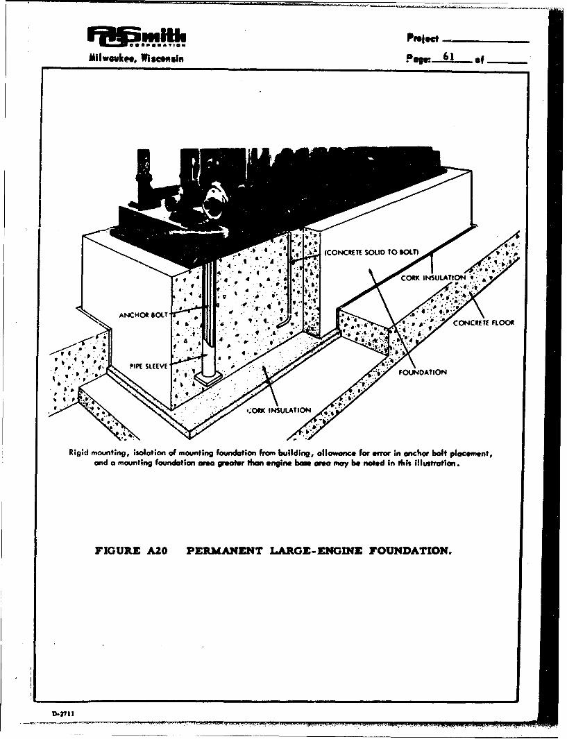
milwoukoi., wiw.oin Pew. 61 _ __
FIGURE ~ ~ ~ ~ ~ CR AO RAETLREEGNFUDTION.UATO
D.2714

-S1" - ----
Pope: 62 of tlwwkee, llisamasn
This acceptable procedure requires flexiblemounting between the set and the sole plates toprevent transmission of vibration to the floor.
c. Portable mountings
Some small engine-generator sets are designed tobe portable and the mounting equipment is includedon the set. Figure AZI illustrates this method(reference A4).
d. Miscellaneous mounting data
When the engine-generator set sub-base (concreteblock, steel or iron base) is not placed on an ex-isting structure of satisfactory load-bearingcapacity, the information in Table A3 can be usedto evaluate the safe bearing capacity of theground (A4).
A factor that should not be over-looked at the timeof designing the sub-base is that clearance (heightabove floor level) should be sufficient to allow thedraining of crankcase oil and radiator waterGenerally, this provision is met if the top of thesub-base is one foot above the floor level.
A distance of two feet between the set and the nearestfixed wall (wall that cannot be removed to facilitateengine repairs)is recommended by all manufacturers.
2. Sound Passage Through Pipes
Vibration is readily transmitted along rigid pipes. Thisvibration transmission should be stopped as close tothe engine as feasible. The pipe lines to the engine-generator set should have flexible connections. Bellowsmade as a continuous piece of metal should be used onthe exhaust pipe since much ttnfavorable field experiencehas been encountered with the woven braid type. The
flexible connections are commercially available fromthe engine-generator set manufacturer. The flexibleconnection should be located six to eight inches fromthe manifold for the exhaust pipe and immediatelybefore the fuel pump (or first item solidly attached tothe engine proper) for the fuel line.
, ,l lIl l I I
8.27P1!

~ Pfr____
Milwaukee, Wisconsin Paqr...63 of___
FIGURE A21 PORTABLE AIR-COOLED GENERATOR.
D-v7t

Pep. 64 *f wIl.k... WglmNd.
TABLE A3
LOAD-BEARING CAPACITY FOR
VARIOUS BEARING MATERIALS
Safe BearingBearing Material Capacity
(lbs/ft2 )
Hard rock - granite, etc. 50,000 - 200,000
Medium rock - shale, etc. 20,000 - 30,000
Hardpan 16,000 - 20,000
Soft rock 10,000 - 20,000
Compacted sand and gravel 10,000 - 12,000
Hard clay 8,000 - 10,000
Gravel and coarse sand 8,000 - 10,000
Loose, medium and coarse
cospact d fine s and 6,000 - 8,000
Loose fine sand 2,000 4,000
Soft clay 2, 000
S- IN l liIP-15'11 . . . .. •... ....... .

F smH5.Phj.
MihwAekee, Wiscousin PqeW_- 65 of
3. Sound Deadening Insulation
It is desirable to install the engine-generator setin a chamber in the engine room. The chambershould be therrnaliy insulated and should not permitengine fumes to contaminate the room air; alsosound deadening material (which is available frommany sources) can be used in the construction ofthe isolation chamber. This would minimizepropa.gation of noise from the engine.
The sound deadening chamber should be so con-structed that the flexible connections of the pipes areon the interior of the chamber. The lower edgeof the sound deadening material should terminate atthe sub-base of the engine if the nature of the floorallows sound transmission.
D.2711"

Pqc66 of IIwke l e06~mkma, Vlssmua
0. Recovery and Utilization of Waste Heat
Four important parameters to be considered in systemsdesigned to recover waste heat from an internal com-bustion engine are (1) the quantity of waste heat available,(2) temperature level of the waste heat compared to theutilization temperature, (3) heat transfer coefficientsexpected in the recovery equipment, and (4) permissiblepressure drop through the recovery equipment such thatengine performance is not affected.
The first parameter determines whether recovery iseconomically justifiable, and the other three parametersdefine equipment specifications. Table A4 gives typicalvalues for heat recovery in a small liquid-cooled engine-generator set.
1. Liquid-cooled engine - circulating liquid
The systems presented in Figs. All, Al3 and A14demonstrate cooling methods for liquid-cooledengines in which all heat is dissipated to the environ-ment. An obvious method of recover Ing waste heatin the liquid would be to divert a portion of the flowstream to an appliance for providing domestic hotwater, tempering ventilation air, etc. Also a pzrtof the waste heat in the exhaust gases can be recoveredat a higher temperature level (Table A4) to be used forsterilizing equipment or even for high temperaturefood preparation.
2. Liquid-cooled engine - ebullient liquid
Ebullient cooling has been a standard practice in oil-test and knock-test engines for many years. Thiscooling method consists of a liquid (usually water)boiling in the coolant jacket and the vapor beingcondensed on a remote cooling coil and the condensatereturning by gravity to the engine. The advantagederived in standard test engines is precise control ofthe engine coolant temper-iture. An important con-sideration for the designer is that structural barriersin the head passages must be avoided so that the vaporbubbles may escape as rapidly as they are formed.
Darts

MI~wek~, POWi 67 *f
0
00 to
1wg
to0 0 O0
00
0 0C 6
1gb4
2 ~0-
U) uU614 A

Engineering Controls, Inc., St. Louis, Missouri hasbeen an active proponent of ebullient cooling of largeinternal combustion engines (much above 45 hp) andhas installed many waste heat recovery systems(Vapor Phase thermal circulation systems). Theusual system consists of an elevated steam separatortank on a standpipe connected to the bottom of theengine coolant jacket. Circulation by thermosyphonprinciples occurs as the vapor formed in the enginepasses through the steam sepcrator to be condensedand returned to the standpipe. The main advantagesclaimed are the self regulation of cooling, fluidcirculation without a pump, and uniform cylinderhead temperatures.
Although ebullient cooling and heat recovery equipmentis generally unavailable for small engines, this systemseems to be appropriate for shelter applications.Steam may be produced from the water coolant or fromwaste heat in the exhaust gases.
3. Air-cooled engines
It may be seen from Table A4 that the heat recoverypotential from an air-cooled engine-generator set islow. The poor heat transfer coefficient at the enginehead surface requires large quantities of cooling airand the waste heat is thus degraded to a low temperaturesuitable only for space heating, ventilation air tempering,and food warming. The exhaust gas heat recoverypotential is identical to that of a liquid-cooled engine.
It was shown earlier that the majority of small engine-generator sets commercially available are air cooled.Thus a problem of suoply (on an emergency basis)could favor heat recovery from exhaust gases, sincethis method is identical with either liquid-cooled orair-cooled units.
4. Utilization of Waste Heat for Cooking
Two types of cooking t0 ,e suitable for waste heatutilization are 1) low t,. rature warming and2) high temperature baking. The engine coolant
LJI

Milveukoe, wi..ne. Pews 69 *1__
is obviously only satisfactory for warming because ofits low temperature, while the hot exhaust gases havepotential for higher temperatures for boiling and baking.These two methods of cooking may be utilized forindividual servings or large batch cooking. However,elaborate equipment most likely will not be used, sincethe shelter is primarily for survival. Post-attackconditions may warrant continued use of the shelteras emergency quarters.
Several devices are described separately but combina-tions are possible.
a. Low-temperature, individual serving
Figure A22 represents a scheme for low-temperaturewarming of individual servings. Water at approxi-mately 180°F from the engine circulates through adevice similar to a steam table. After passing theindividual containers, the slightly cooler water passesover the coils of a heat exchanger and then to themixing tank where it is pumped into the engine blockand repeats the cycle. The pump in the line to theoutside heat exchanger is thermostatically-controlledby the temperature of the water entering the engineblock and is actuated when this temperature exceeds160 0 F. If the temperature of the water entering theblock drops below 140 0 F, a manually coittrolledvalve can be opened allowing warmer water to reachthe mixing tank, thus increasing its temperature.Also a manually-controlled bypass valve allows thewater to flow directly from the engine coolant outletto the mixing tank. This prevents excessive enginecooling when very large quantities of food arestarted to be heated.
S.
The solution to the problem of maintaining waterin the line leading to the outside radiator isidentical to that shown in Fig. A13.
b. Low-temperature, large-batch serving
If the food is to be warmed in a large container, thesmall individual cans in Fig. A22 are replaced by alarge container. The design of the warming tank
9.2711I

NLd44'G 7*V
SAVINIM'rtr

lIwuukee, WiMMO. P9f_.2.L._ o
should be such that there is a tight fit between thecontainer and the warming tank to prevent waterleakage. Also a large amount of liquid shouldflow past the container to increase heat transfer.Again the manual-bypass or thermostaticallycontrolled valves prevent excessive engine coolingduring initial startup of warming.
c. High-temperature, individual serving
Figure A23 is a method for the high temperaturecooking of individual servings. This is accom-plished by simply directing the hot (1200 0 F)exhaust gases into gas-tight enclosure which isfitted with individual containers. These individualcontainers can be replaced by a grill for fryingfoods. The cooking area is hooded so that cookingodors can be vented to the outside. The hood isequipped with a device which allows it to be raisedand lowered. The exhaust gas is simply vented tothe outside after passing the cooking area. Onedisadvantage of this system is that there is nocontrol over the heating. When the engine-generator set is running, the cooking area maybecome excessively hot.
d. High-temperature, large-bbatch serving
Figure A24 represents a method of uoing the exhaustwaste heat of the engine-generator set for bakingor some other type of high-temperature, large-quantity, food preparation. This method directsthe hot exhaust gases around an oven, which issealed so that exhaust gases can not get into thebaking area. An alternate duct, equipped with agas-tight box to prevent exhaust gas from leakinginto the shelter contains a manually controlleddamper, (A), which is used to control the oventemperature by controlling the flow of the hot gases.Damper B could be controlled by a bimetallic strip.
Damper A should be manually set to optimize thecontrolling function of damper B. Damper Ashould never be allowed to close completely; amechanical stop or hole in the demper would be
D-2711

POWj.72
F/cs A 23 HIGH TEMPERA 7Z'RE COOK/MG 0X' SAeK/MG(A/ao cowrpcv-s)
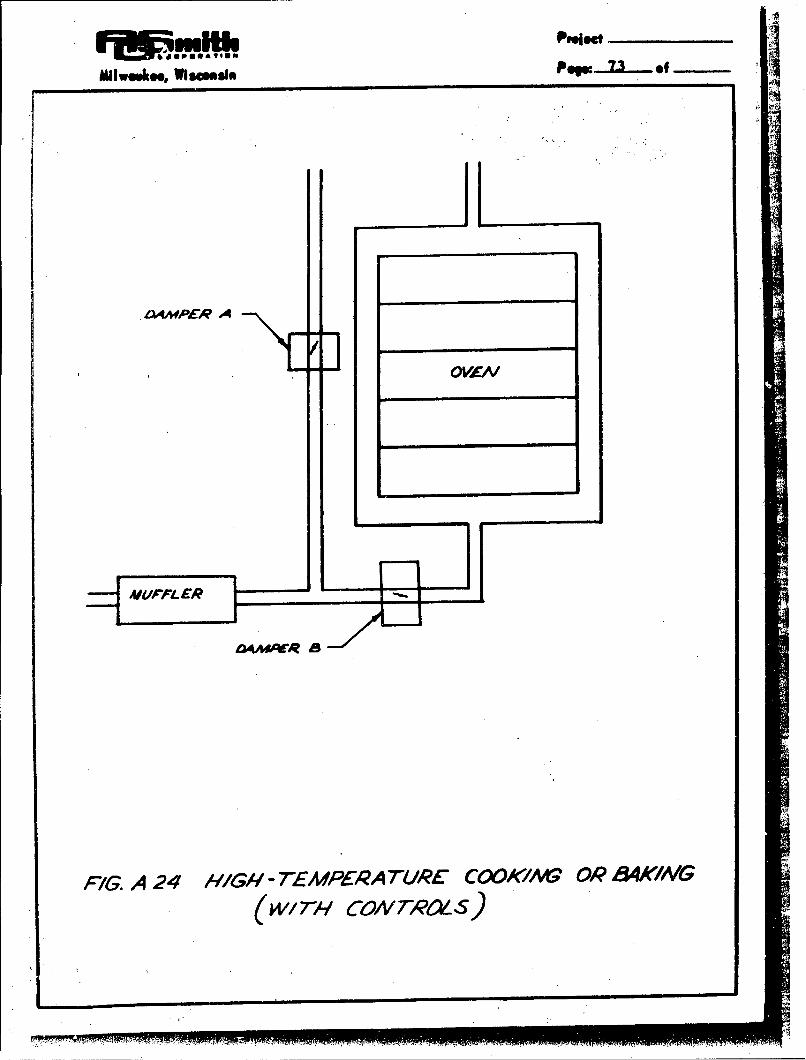
O.4mAER A
-OVZW
FIG. A 24 /1/GIl - T-EMPEIRA TL/PE COOK/At' OR 8AWING
(w17w CON7AM~S)

Pew. 74 of
bufficient to prevent complete closing. Thus the
engine can always exhaust the products ofcombustiot.
5. Utilization of Waste Heat for Water Heating
Many of the schemes shown earlier (Figs. All, A13and A14) had hot water supplies as an integral partof the cooling system. The engine coolant could
either be utilized directly for shelter activities or itcould be used to heat water in a heat exchanger. How-
ever, if air-cooled engines utilizing contaminated air
are to be used as a shelter power supply, the exhaustgas would have to serve as a heat source for hot water.
a. Liquid-liquid heating
Figure AZ5 is similar to Fig. A13 except thatin Fig. A2S the heat remooved by the heat ex-changer coils is carried by water through another
heat exchanger before it is finally rejected to theatmosphere. The intermediate heat exchangeris located in a tank of water to be heated for
shelter use. Again the temperature of the waterin the mixing tank controls a pump, which keepsthe engine water inlet temperature constant.
The system is also equipped with the usual ex-pansion tank and means for replenishing waterto the closed system.
b. Gas-liquid water heating
Figure A26 shows a method of utilizing hnv engineexhaust gases to heat water for shelter use.
A coil containlng water is surpended in theexhaust duct. As the water is heated it circulates
by free convection. The cooler exhaust gasesleave the shelter through the exhaust pipe. Thiswater heater construction is similar to the mono-
tube in the flash boiler shown later in Fig. C5. Ofcourse the hot exhaust gases could also heat waterin a tank by passing through tubea as in a fire tubeboiler. This method of heating a fluid is also
shown later in Fig. C5.
l Di•

Milwouk.., Wiaceusin PeWe 7S of
WAT~
FIG. A 2S LIQUJID LIQUID WATER HEA T/NO

'Po. 76 *1wum ~ml
mcwEJ6i4 sr P/A~E --IP~r
AW - GASES AAWN EWAISE -r
P7c-G. A 2 6 GAS-LIQUIW WA TER H4EA TING'
.. ma

Mlvlwkn Vismdsn POg 77 of
c. Steam generation
Figure A27 is a sketch showing a method by which steammay be generated for shelter use. Hot exhaust gases arepassed over incli•ed finned tubes containing wat-?r. Someof the water is evaporated and is stored as steam in the
steam chest above. The inclined leg is present to over-come the back thrust created by the movement of thesteam as it is formed; the tube as insulated except in
the exhaust duct to prevent steam formation elsewhere.The exhaust gases are vented to the outside in the usualmanner after some of the heat has been salvaged. Water
is fed into the system in a manner shown in Fig. A13.
The steam may be used for sterilizing utensils andequipment, boiling clothes, and to operate an absorptionair conditioning system such as an NaOH unit which alsooffers a possibility of carbon dioxide control in a shelter.
H. Utilization of Excess Shelter Air
It is anticipated that waste air from the shelter-air-condition-ing process will be more than sufficient to supply thecombustion air for the engine-generator set as well as pro-vide proper control of noxious gases. Therefore the remainderof the waste air may be utilized 1) to perform evaporativecooling of the engine, and 2) to provide combustion air forauxiliary heat sources.
I. Evaporative Cooling Process
Figure A28 shows a method to utilize waste shelter air
in an evaporative cooling process for engine cooling
requirements. Hot water from the engine block ispumped through a coil, which is immersed in acontainer of water, and is then returned to the engineblock. A valve, which is controlled by the temperatureof the water in the engine block, controls the rate at
which shelter air bubbles through the water reservoir to
maintain the engine coolant temperature at approximately160 0 F, since the cooling rate of the system increaseswith air flow rate. An alternate procedure would be topump the engine coolant directly into the reservoir andadd makeup water to replace that which is evaporated.
D-ZIII

-e . 78-o
710 Sr7AC/<
_____ ____ ____ __ IWA7rER
Mv7 ExIA es r cA4Sws
1NS~l-ATED
FAG. A 27 SHEIL TEP3 STECAM GENERAT7OR
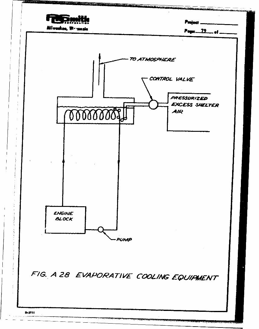
S.... .. . F-uEXCESS f_ _____
IAIR
PUMP
FYG. A 28 EVA PORA TI 1E COOL /A(G E4UlA/WEN 7
0.-713

The closed-system cooling system for the engine
coolant in Fig. A28 would require the same chargingarrangement shown in Fig. Al 3.
The advantage of the evaporative cooling process shownin Fig. A28 when compared to the method shown inFig. A14 is that filtered air is used to promote rapidevaporation rather than sprays in contaminated air.
The advantage of the evaporative cooling system over
the recirculated-water cooling system (Fig. AA3) and
over the well-water cooling system (Fig. All)
respectively is that ths system in Fig. A28 does not
require an extermal radiator and each pound of water
lost removes approximately 1000 Btu (latent heat of
vapo rization).
The process by which heat is removed from the shelter
is shown in Fig. A29 on a modified psychrometricchart. A typical ideal process would require shelter
air at the conditions of point A. Thius air would be
saturated and follow the saturation curve to point B
where it would be discharged from the shelter. The
amount of water lost per pound of air leaving the
shelter in the process is the difference in the ordinates
between point B and point A, while the heat removed
per pound of exhaust shelter air is the difference in the
values of the diagonal lines passing through point B and
point A.
2. Extensive Use of Filtered-Air Cooling
If an unlimited supply of filtered shelter air is available,
an arrangement similar to Fig. A30 (but without the fans
and external radiator) may be used. This system is
based upon the requirement that the shelter air is
exhausted at a pressure high enough above atmospheric
to force the air over and around the engine-generatorset with sufficient velocity to cool the unit. To cool a
typical 5 KW engine-generator set requires approximately
700 CFM. This is enough air to maintain the CO 2 contentof air at a safe level for 230people (assuming 3 CFM/
person) or to increase the allotment of air for 50 people
to about 14 CFM per person. A 5 KW engine-generator
I-U

............ .~e d . -
.iR.
AIR HEATING
AIR rACAIPERA7ME
67-1G. A 29P EVAPORATI77VE' CCOL NG PROCE-SS
M-. I"M77 .9VI 'lFf,"lMMI"RNr!1ýRw

PW 82 lir- dea, 7 1- a~i
,FAg. A 30 P'IL.TERED -AIR COOL lAG S YS7EMW

Milwaukee, W1600u10 PWm .... 83 9
set supplying the needs of 50 people will provide 100watts per person while the same engine-generator setsupplying the needs of 230people will supply only 21watts per person. Since it is anticipated that 21 wattsper person will not be sufficient power, the possibilityof supplying exhaust shelter air as a sole means ofcooling the engine-generator set will not be too likely.
A second solution to the problem of cooling the engine-generator set with exhaust shelter air is suggested by thefailure of the first. If there is a limited supply of shelterair available (say 150-200 CFM or an amount sufficientto maintain safe CO 2 concentrations for 50 people) at apressure sufficiently higher than atmospheric to causeair flow at an adequate velocity, this air can be usedto cool the generator and remove the heat transferred tothe air by radiation and convection from the engine.The engine itself may be cooled by water and an externalradiator in the manner outlined in previous sections.
If approximately the same amount of air is availableas in the preceding method, but its pressure, andconsequently its velocity is too low for the properamount of heat to be transferred per unit time, amethod illustrated in Fig. A30 can be used.
3. Auxiliary Combustion Process
The question of whether or not excess shelter airshould be utilized for combustion processes such aswater heating, gas-fired absorption systems, and gaslighting is a matter of economics. The following questionsmust be asked-
a. Does the use of combustion processes reducethe electrical load in the shelter and thus notrequire generation of high-cost electricalpower only to have it do tasks suitable forheat directly?
b. Is the cost of the fuel, burner, and other equipmentrequired to provide hot water or cooking energyless than the cost of a heat exchanger system tosalvage heat from the engine when it is operating?
D.2711

pqu 8 4 o - Iwukeo Wssmoa
The first question may be answered quite readily.If the power-producer efficiency is 15 per cent andthe combustion efficiency is 7S per cent. it wouldbe five times more efficient to use heat directlyrather than degrade the electrical power into heat.Of course, resistance heating is often moreconvenient than combustion.
The second question was answered tacitly during thisstudy when a request for a 25,000 Btu/hr waste heatrecovery unit was declared to be too small to *oe ofinterest to many manufacturers of heat exchangers.On the other hand, burners, water heaters, andsmall-size cooking equipment utilizing combustionprocesses are readily available (mass produced).
Figure A31 illustrates a means to use waste shelterair in a combustion process. A suitable burner,along with a throttle to control the rate of air flowand a manual valve and damper to equalize theshelter and burner pressure during ignition, isinstalled in the air exit duct A manometer allowsthe operator to equalize shelter and burner-chamberpressures. Heat is removed by a water filled coilin the flame, while the exhaust gases pass out ofthe shelter through a vent.
I. Criteria for Equipment Selection, Installation,Maintenance, and Utilization
1. Engine-Generator Equipment Selection
a. Acceptance tests
The conventional method of evaluating an engineby its hours of continuous operation beforefailure is not necessarily a reliable criteria forthe approval of an engine for the shelter appli.cation since it is known that this applicationrequires a considerable number of cold startsduring the exercising period. This "cold".operation of the engine causes considerablygreater wear rates than the operation of a"hot" engine (Fig. A9). Therefore, it is
3.713

N 'f#4AT REMOVOl 1
7RM4A#4iTr BME
716. A 31 BL/PNER P0/?AS/ETE
D.2t I1

PO 86 ofIII .. ualosMIwwuke, W119ansi
desirable to (1) develop a test procedure forevaluating engines for the shelter application and(2) determine if this tesi can be correlated withthe available continuous- operation data.
It is realized that corrosion and wear are thttwo factors that would be most likely to causefailure of an engine-generator set. 7herefore,it is desirable to evaluate the effects of thesephenomena. The ten-year standby life require-ment of the units makes actual field testingimpractical. However, a realistic acceleratedtest appears to be possible. The factors in-fluencing the tests and the accelerated testprogram are discussed below.
a-I. Corrosion
All external parts of the engine-generatorset will store ten years if kept reasonably
dry. This can be accomplished by heatingthe set with light bulbs and thereby causingit to be the warmest item in the vicinity.Condensation will occur at the coldest spotin !he system and moisture on the set dueto condensation during stand-by will beeliminated. Possible wetting of the engineby the entrance of liquid water into theengine room can be eliminated by properdesign of the room and ventilation system.Also, the installation of sump pumps forusage in an emergency can be a furthersafeguard. The large number of ten-year-old engines and generators that are still
functioning is evidence that keeping theoutside of an engine-generator set storedunder reasonably dry conditions will pre-vent failure due to corrosion of the externalsurfaces.
The internal surfaces of the engine on theengine-generator set will corrode if notprotected by a layer of lubricating oil andmade free of condensation. This lubricating

MIwlkee, WVie•os Pow 87 of
oil is subject to drainage from the oiledsurface; hence, if the surfaces are not
re-oiled with oil from the crank case, theywill corrode. However, field experience
by engine manufacturers shows that if the
engine-generator set is exercised once a
week for one half hour, this type of corrosion
(and also corrosion of the collector rings in
the generator) is not a problem. Sinceweekly exercising is advised for the shelter
application, the corrosion of the interior of
the engine or the generator should not be a
serious probiem. Consequently, an ac-celerated corrosion life test of these
components is not essential.
a-2. Wear
The above discussion indicates that wear isof greater importance for evaluation by anaccelerated life test. Reference A5 indicatesthat molt rapid wear occurs during the firsthalf hour of engine operation (Fig. A9). This
is definite evidence to support the fact that
engine-generator set manufacturers do notexpect maximum life from their engines whenweekly half-hour ex~ercising periods are used
for a ten-year period. The reference cited
reports a very significant fact that the data
shown in Fig. A9 were reproducible whetherthe engine had been shut down for severalhours or as long as several days. The only
requirement was that the shut-down period
be longer than two hours between runs.
This observation indicates that the wearrate of an engine being exercised weeklyfor a half-hour period may be dupli-catedby a test program in which the engine is
cooled to expected shelter temperature,exercised, and recooled to shelter tempera-ture on a 6 to 12 hour cycle. Hence, ten-yearwear due to exercising could be duplicated ina period of 130 days.
D-I•I!

WIWMWOee WIN=in
The absence of a suitable approval test for theshelter application suggests that a temporarytest procedure require that the engines have atleast 1, 000 hours continuous operating life atfull load. This more conservative test wouldeliminate the low cost economy engines fromshelter application and allow acceptance of theheavy duty engines.
b. Engine-generator set design
There is a considerable difference in designprocedures among the various manufacturersof engines. Therefore, a detailed evaluation ofspecific designs was considered beyond the scopeof this program. However, several designfeatures appear sufficiently prominent that theyshould be mentioned.
b-l. Valve faces and seats
The wear of valve faces and seats is themost probable source of engine failure.The use of stellite valve faces and seatsis highly desirable for the shelter appli-cation because the engine would be uselesswith burned valves and repair would bevery difficult.
b-2. Bearings
Attempts to eliminate bearings foreconomical purposes, such as havinga crankshaft supported directly on a diecasting as a bearing surface, should beavoided unless there exists definiteevidence that the omission of the con-ventional bearing (bushing, ball bearing,roller bearing, etc. ) will not causepremature failure of the engine-generatorset.
b-3. Castings
Cast iron is preferred to die cast aluminumconstruction. If the cylinder block is diecast, it should have a cast iron sleeve for
94M

IM WmOCOmImF iii@
WIweeko. WOMIsN PqOW .. _ of
the cylinder walls for better wear resist-ance. Another disadvantage of aluminumcastings is the possibility of stripping threadsduring emergency repairs; cast iron threads
are less oftep stripped.
b-4. Magneto
The points of the magneto may become pittedor corroded and thereby cause improperfunctioning of the engine or a complete fail-ure. It would require less skill to replacea magneto that can be removed from the setas a unit than it would to replace the pointsof a magneto that had the components per-manently attached to the engine (such ashaving the magneto housing an integral partof the flywheel.
c. Instrumentation
The crucial nature of an engine failure indicatesthat a certain amount of instrumentation is desir-
able in order to anticipate and prevent trouble,
c-I. Temperature gauge
Liquid-cooled engines should have tempera-ture gauges in the liquid coolant outlet toinsure that excessive coolant temperaturesare detected. A temperature above 200OFwould indicate an unsatisfactory operatingcondition.
If the engine is air cooled, the temperaturegauge should be located in the air streamimmediately before the engine -generatorset. The upper temperature limit of thecooling air entering for safe operation wouldbe 120 0 F.
For engines cooled by well water or othercontinuous water supplies, the inlet watertemperature to the engine should be checked.
D.2fl1

POW- 0 of
The inlet water temperature should rise toat least 140°F in less than one half hourafter starting of the engine and should notfall below this temperature during engineope ration.
c-Z. Oil pressure and oil level guage
If the engine has an oil-pump system, an oil-pressure gauge should be available to deter-mine if the oil pump is functioning satisfactorily;
The engine should be equipped with an oil-levelgauge. Provision should be made to add oilwhile the engine is running.
c-3. Intake manifold pressure gauge
Unusual circumstances for operating the enginemight result in overloading the engine andsubsequent premature failure. A pressureguage on the intake manifold would indicatethis situation. The manifold should alwaysbe at a partial vacuum for continuous full-loadoperation. The application of engine loadmight momentarily cause this vacuum to bereduced.
d. Instruction manual
The engine-generator set should, be supplied withthe manufacturer's instruction manual with1) instructions for starting the set, Z) proceduresfor detecting engine or generator troubles, and3) repair procedures. These manuals would bediffercnt for the various manufacturer's engines,but they should contain sufficient detail that areasonably intelligent person could handle minorrepairs. The instructions should include the fol-lowing information in detail:
d- 1. Starting
(a) Precautions before starting (oil levelcheck, etc.)
(b) Starting procedure
III I

Mlllwukne WImOIN p...... of
(c) Carburetw- ae!kutipient
(d) Throttle adjustment
d-2. Detection of troubles
(a) Ignition system malfunctions
(1) Defective spark plug
(2) Defective magneto
(3) Defective wiring
(b) Fuel system malfunctions
(1) Gas supply to fuel pump
(2) Gas supply to carburetor
(3) Flooding
(4) Insufficient fuel
(5) Idle-adjustment
(6) Rich-lean mixture adjustment
(7) F. ugged or restricted exhaustmanifold
(c) 'Repair and maintenance procedures
(1) Cleaning, re-gapping and replacingspark plugs
(2) Replacing magneto
(3) Replacing distributor points
(4) Changing oil
(5) Replacing oil filter
(6) Cleaning air filter
(7) Cleaning carburetor
"MmPOPMP IF

POW 92 of Il ! a
(8) Replacing gaskets damaged duringrepairs
(9) Lubricating the engine
(10) Cleaning generator collector ringsand replacing generator brushes andbrush springs (if feasible).
(11) Replacing defective sw.-, hes at mainpower distribution station.
These instructions should be detailed. For example,starting the engine by a rope starter should includean instruction such as: "manually take the engineoff the compression stroke before pulling the rope".This is indicated by the ease with which the ropecan be pulled. The instructions should be explicit.If a blue wire is used in the set, the instructionsshould refer to the blue wire instead of just thewire. Written instructions should be supplementedby diagrams to both insure that the engine repairman knows what to do and to allow him to "doublecheck" himself so that he is more certain thatwhat he has done is correct. This is important inthat if the difficulty is hard to detect or correct, hecan be sure that portions of his completed work aresatisfactory. He will not then waste time in dupli-cating past efforts because of indecision.
The instruction manual should include a tool andmaterial list for accomplishing the above mentionedprocedures for detecting, cleaning, and repairing.
2. Auxiliary Equipment Selection
a. Exercising equipment
a- 1. Manual operation
The only equipment r,_.qui red for manualexercising during the stand-by period is aclock (or watch) and a pencil and notebookto record the length of the exercise periodand the date. This essential record ofcumulative running time could be used toassure oil changes after 26 hours of operation.
tLm

hMlveskee, Wismcd,, Pqow.2_3 of
Also detailed instructions of the exercisingprocedure would insure proper attention byvarious service personnel.
An air purge fan used to ventilate the shelterengine room and the engine air filter and fuelfilter should be cleaned at least yearly; thecleaning date should be recorded. In general,a log indicating exercising history should bemaintained.
a-2. Automatic operation
Various degrees of automation could be usedduring the exercising period. The engine-generator set could be automatically startedand stopped at the desired times with availableequipment. This equipment should be (andgenerally is) equipped with a safety circuit sothat if the engine does not start in a reason-able number of attempts the starting procedurewill not be repeated wid cause damage. Theengine-generator set should also be equippedwith a temperature-controlled safety deviceto prevent overheating the engine. The coolingsystem will be novel for the shelter applica-tion, and consequently precautions should betaken until reliability is proven by field experi-ence. If the engine has a pressurized oil system,the automatic exercising system should have anoil-pressure safety device to prevent the opera-tion of the engine with low oil pressure.
The installation of automatic exercising equip-ment does not entirely eliminate attention bypersonnel. Oil changes, filter cleaning,servicing, and checking of the generator arestill required.
3. Application of Load
a. Electrical load
The starting load for electric motors is higher thanthe normal operating load. In order to load thegenerator to its maximum capacity, the inductive
P-2'?!11 " '' " ..

a.... 94 9f
loads (motors) should be applied first. Therefore,a sequence for applying the various electr ical loadsis required. This method of load application can beaccomplished by a series of hand switches. Thetime internal between the closing of the switchescould be short (one second) as this peak transientload is of very short duration. However, the orderin which the loads are applied is important. Thelargest motors should be started first, the smallermotors next, and finally lights and pure resistiveloads should be applied.
Equipment for automatic sequencing of the startingloads can be purchased (AS). If this arrangementis used, provision should be available (generallypart WE' this equipment) to eliminate the least crucialpart of the load in case of severe overloading.
b. Mechanical load
The possibility of having part of the load such asblowers driven directly by the engine instead ofusing electrical power from the engine-generatorset should be considered. This could be accom-plished by a belt-driven arrangement. The idlerpulley could be used to act as the clutch. However,clutches are available for such an installation. Themechanical load would be started last in the loadapplication sequence as it would have the startingcharacteristics of a resistive electrical load due tothe ability of the clutch to gradually apply the load.
The use of a mechanical drive would result in(1) the elimination of a motor, (2) a smaller-sizegenerator requirement, and (3) more efficientutilization of the fuel supply because the generatoris only 70 per cent efficient.
4. Shelter-Power Manual
The engine-generator set manual was concerned withthe operation and servicing of the engine-generatorset. A similar manual should be prepared by theshelter-power-system designer. It would contain.among other data deemed pertinbnt by the designer,
'M!

MIlwomk e, WimsumaPseg 95 9f
instructions for operation, inspection, maintenance, andemergency procedures concerning the fuel supply, cool-ing system, exhaust system, and electrical system thatwere not part of the engine-generator set. The load-application sequence for starting the engine-generatorset would also be included in this manual. A recom-
mended procedure for reducing the load, if necessary,should also be included; this should contain descriptionsof results to be expected for certain shelter activities incase of power failure in order to facilitate decisions thatwould have to be made at the time. For example, it
may become evident that longer occupancy would be re-
quired; hence, fuel must be conserved.
5. Engine-Generator Set Installation
a. Procedure
The engine-generator met should be installed asrecommended by the manufacturer. The mostsatisfactory methods for fuel storage, waste heatrecovery systems, and cooling systems should be
utilized. Several suggested asetshods were pre-sented earlier in this study. The first test runshould be made according to instructions. If the
engine had not had a break-in period at the factory,the manufacturer's break-in instructions should befollowed. If not specified, the break-in oil shouldbe a S. A. E. 30, non-detergent oil to prevent glazingof the cylinders. The purpose of the break-in period
is to allow the newly-machined engine surfaces to"wear in" to give optimum engine performance,with respect to minimum oil consumption, maximum
life expectancy, and maximum efficiency.
b. Inspection:
The following precautions should be taken regularlyduring the stand-by period-
b- I. Check the oil level in engine and add oilif level is low.
b-2. Drain water from the water trap in theexhaust line.
D.RIii i

PoS: ,,, 96 of oo,
b-3. Check the fuel gauge for excessively fastconsumption of fuel. This would indicate im-proper operation or a leak in the fuel line.
b-4. Check the fuel line and joints for leaks. Majorleaks will be indicated by liquid spots on thefloor.
b..5. Check the water level in a liquid-cooledsystem and add a rust inhibitor once a year.
b-6. Check the water system for leaks.
b-7. If the engine has a fan belt, check the sidethat contacts pulleys.
b-8. Check the equipment for loose bolts dueto vibration
b-9. Follow the designer's recommendations forbelt tension. A belt that squeaks during con-stant load operation is probably too loose andwill glaze and wear fast due to slippage. More
tension on the belt is required. Excessivetension causes excessive loads and wear onshaft bearings.
b-10. Check the wiring for cracks in insulation,particularly high voltage wiring from the coilto the spark plugs.
b-l. If the system has rubber hoses or tubes, checkf•or bulges and soft spots. Replace hoses ortubes if these are detected.
b-12. Check the water level and hydrometer read-ing of batteries.
6. Engine-Generator Set Maintenan e
a. Preventive maintenance
Engine-generator sets require surprisingly littlepreventive maintenance. The following precautionswould be sufficient for a preventive maintenanceprogram:
m-II

PMie
MIAiWu&.., Wisces 5 5. Poor. 97 of_
a-I. Clean and re-gap the spark plugs annually.
a-2. If engine has a distributor, check the pointsannually and replace if they are pitted.
a-3. Change the oil and lubricate the engine accord-ing to manufacturer's recommendations.
a-4. Clean the oil filter and air filters according tomanufacturer's recommendations.
a-5. Clean oil and dirt from the ignition system
wiring annually.
a-6. Replace the starter rope if it becomes worn.
a-7. Adjust the carburetor (only if necessary) accord-ing to the manufacturer"i instruction manual.
b. Emergency repairs
The following spare parts are recommended for theengine-generator set:
b-I. Gasoline engine
(a) spark plugs
(b) distributor points
(c) fan belt
(d) magneto
(e) generator brushes and springs
(f) air filter
(g) fuel ;ilter
(h) carburetor
(i) gasket overhaul set and gasket compound
(j) can of cleaning fluid
b-2. Diesel engine
(a) fuel injector
(b) pertinent items above
D-2711

P etl.: ..... 8 of .......... i..iPaojecte~tP.,.: 98 *f
MIlweuke., Vlsmonuis
The purpose of the gasket overhaul kit is to allowan elaborate overhaul in the event that it is nec-essary, and that qualified personnel happen to beavailable. It is not exceedingly difficult to over-haul small engines. The cleaning fluid would be forcleaning the parts (particularly gums from thecarburetor.
c. Lubrication
In addition to the oil changes, the equipment may beequipped with oil wells and/or grease fittings. Theseshould be lubricated according to the manufacturer'sinstruction. The oil should be stored in one-quartsealed containers and the grease in conventionalmetal containers. These containers should be storedin a reasonably dry place so that they will not corrode.
7. Mode of Operation
After the engine-generator set has been installed, pro-cedures for operation both during the stand-by periodand the time of actual usage are required. Theseprocedures are described below.
a. Stand-by period
a-I. Purge the engine room with fresh air toeliminate the danger of a combustible mixture.The procedure would be to start an air purgefa-n or blower (operated by commercial power)
and operate it for a time (determined by thesize of the area to be purged).
a-2. After the air purge was completed, theengine would be started.
a- 3. Soon after starting, the sequential applicat:onof load would be executed. Among the itemsto be started would necessarily be the coolingsystem. This would not have to be the firstitem started, but the ent~re sequential startingprogram should be completed within 2--3minutesafter the engine started. If diesel fuel or gas-oline is being used, the load should be 90 percent of the rated engine load. If LP gas is the
ID,,,rII

S• " ... ..' ....., . . ..* .• .• ......
mpm.
Mlleukl., wisclesi. POW ef
fuel, the load should be 50 per cent of therated engine load. These figures areselected to prevent carbon build-up in theengine.
The large electric motors should be startedfirst. Initial transient currents 500 per centof rating may be expected (A9). If this ismore than I 10 per cent of the generatorrating, low voltage motor starting boxesshould be used. The mechanical load shouldbe applied last if the load is driven througha clutch.
a-4. If personnel are on hand (equipment not onautomatic cycle), a check should be made todetermine if equipment operation is consistentwith the manual and the proper correctionsmade.
a-5. The engine-gee erator set should be operatedfor one half hour.
a-6. When removing the load from the engine-generator set, the reverse procedure fromsequential starting would be satisfactory.
a-7. The engine should be stopped.
b. Emergency period
The starting procedure would be the same as duringthe stand-by period. However, if the commercialpower for the air purge fan was not available, thisstep would have to be omitted.
If power is not required at certain times, thequestion arises whether or not to shut down theengine-generator set. If the anticipated time isless than 30 minutes, the engine should be allowedto function on the regular cycle. If the time isgreater than 30 minutes, the engine-generator setshould be shut down. These recommendations are
D-2711!

S...... =.. i.L. of "*w u ee, wi .. .. i•.
made so that (1) a hot engine is not started andstopped unnecessarily, (2) undue adjustment ofspeed is not made, and (3) fuel may be conserved.
8. Comparison of Competitive IC Engines
If a standard acceptance test has been adopted andseveral manufacturer's engines are available andsatisfactory, a decision has to be made as to whichone should be selected. The factors to be consideredare:
a. Cost
b. Service by the manufacturer's representativeafter installation during the stand-by period
c. Life expectancy
d. Ease of starting
e. Simplicity of maintenance
f. Simplicity of inspection
Since the acceptance test will require experimentaldata concerning the effects of a large number of coldstarts on engine life expectancy, it is impossible toquantitatively evaluate these properties, but the fol-lowing aspects of the evaluation should be considered.
,a. During the 1-year stand-by period much data onthe engine-generator set will be accumulated.Periodic inspection by trained personnel will makethese data much more useful than observationsmade by untrained personrel.
b. If the life expectancy of the engine-generator sets isconsiderably longer than the acceptance test require-ments, this factor loses significance.
c. All the sets should start relatively easily. However, ifany particular one has more starting difficulties than therest, it should be eliminated from future application.
d. Undue maintenance problems or difficulty in inspection(such as checklng the oil level in a hot engine) shouldbe important as well as purchase price.
Iv I I II-

Ulieu.. V..cssl P•p~L.. f__
il~eA0, Wise"i POW 10l 1 f
J. Phisical Arrangement of the Shelter System
1. Engine Generator Set Location in the Overall Shelterair Stream
The air passing over the engine will contain obnoxious oilfumes and the air discharging from the cylinders duringthe combustion process will contain noxious carbonmonoxide and other products of combustion. Therefore,once the air has passed over or through the engine itshould be isolated from the "breathing" air used inthe shelter even though it may still be used for a heatexchange or a combustion process.
Therefore, the engine-generator set (if it uses shelterair) should be located near the waste-air exit of theshelter. If there are no heat exchange processes toscavenge waste engine-generator heat or combustionprocesses that utilize the excess air from the set, theengine-generator set should be located next to an airexit in the shelter. If heat exchange or combustionprocesses are used, these processes should be the onlyitems in the air flow stream between the engine-generatorset and the air exit of the shelter.
2. Fuel Location in the Overall Shelter Air Stream
The fuel supply should be isolated from the shelter andarrangements should be made to continuously purgethese areas having any fuel storage with a small streamof air to prevent gases from the fuels from reachingsufficient concentration to cause an explosion. The fuelstorage area should not normally be occupied by peopleor oxygen consuming equipment; therefore, the quantityof purge air required would not be large. The exactquantity of purge air required would be determined bythe capacity of the fuel storage facility and the degreethat the facility was properly used.
The most fool-proof procedure would be to use as muchpurge air as possible and vent the purge air to the out-side through an explosion-barrier screen (similar to*bose on mine lanterns). This precaution would reducefuel vapor concentration and only permit explosionsoutside of the shelter provided that suitable precautionsagainst explosion in the fuel storage area are taken(elimination of rparks and heat).
D-flII

POWe.J..L. 10 f -50ý a Irw..kee, W 4u00au
3. Location of the Engine-Generator Set and Power Loads
a. Electrical Power Distribution
The location of the engine-generator set relative tothe electrical loads is not critical because electricalenergy is easy to distribute. The distribution systemshould consider such factors as heat or moisture,decomposition of insulation, adequate size wi ring,and proper fusing to minimize the effects of localshort circuits.
b. Mechanical Power Distribution
If a fan is a large power load, the inefficiency of thegenerator could be eliminated by using engine shaftwork directly by means of a mechanical linkage(probably belts). A clutch would be required forlarge loads. One engine could drive both anelectric-power generator and a mechanical load.The mechanical power transmission would besimplified if the mechanically driven device waslocated near the engine.
c. Hydraulic and Pneumatic Power Distribution
These systems would have flexibility in locationwith respect to the power produce-. A majordifference between these systems and the electricsystem is that usually power distribution fails ifthe electric wire breaks. This is generally not thecase with hydraulic or pneumatic systems; howel-er,these systems might need recharging before beingput back into service. An inexperienced pert an,with a minimum of instruction, probably wouldrepair an electrical distribution line easier 1hanhe could repair a hydraulic or pneumatic system.
4. Waste Heat Loads
The transmission of sensible heat always involves a heatloss. This can be minimized by short lines that areinsulated. Location of the heat trinsmission lines sothat energy lost in transit does not flow back into theshelter area should be studied for each i,.ividualsituation.
'|,I I .I - 77 70 0 1 " T M

mi0tWMIw..ke., WsmoPw 103 of
5. Space Requirements
The engine-generator set enclosure should have atleast six inches clearance between the set and theenclosure wells. As a general rule, which may pos-sibly be violated occasionally, the four sides of theenclosure should be removable for engine repairs. Aminimum distance of 2 feet from the engine to thenearest permanent wall is good practice.
If the engine-generator set selection has not been madeand the designer wishes to use a rectangular block forrepresenting the engine-generator set and the servicearea for layout purposes, a 6 foot wide by 4.6 foot highby 8. 5 foot long rectangular parallelepiped would berecommended for an enclosed 5 KW set. These dimen-sion. include the 2 feet clearance on all sides.
D.VIi
__. .....m . . ... .... ........ .........
POW 104 ofMI|u Wismuia
VII. AC GENERATOR SELECTION
A. Introduction
Considering that an exercising procedure is required for theengine during normal stand-by duty, it is not anticipatedthat the generator will become demagnetized nor be subjectto failure. Therefore, the discussion that follows is limitedto description of the various units rather than details onmaintenance and repairs. Reference BI contains most ofthe source material.
In subsequent discussion, the notation refers to the field asthat winding which, when excited by a dc power source, pro-duces a magnetic field. The armature winding is that windingwhich, due to relative motion between the armature andmagnetic field, develops an induced voltage to power anexternal electrical lord. Either the armature or the fieldmay be rotated.
B. Types of Rotary AC Generators
The generation of ennf in an armature conductor depends onlyupon the relative motion between a conductor and magneticfield. Therefore, either the armature conductor (whichdelivers electrical power to external loads) or the magneticfield may be mechanically rotated.
1. Rotating - Field Type
a. De sc ription
The rotating salient-pole may be excited by eitherof two types of dc voltage so,;rces. Electrical poweris delivered to the load by the stationary armaturewinding.
a- 1. An external dc source is connected to therotating field through slip rings and brushes.
a-2. A brushless shaft-mounted ac exciter on thesame shaft as the main field provides dcusing silicon diode. rectifiers which rotate withthe field and exciter.

MIOpwe. vismaw. POW I O: Of
b. Applicaticn
The rotating-field generator is used for high voltage,high amperage, high speed applications because ofthe elimination of brushes in the load circuit, andease of applying high voltage insulation. It is generallynot available in a 5 kva or lower power rating becauseof cost considerations. There are also constructionaldifficulties (insufficient space on the smaller rotors'for the salient-pole construction).
c. Electrical Characteristics of Rotating Field Generators
c-1. Terminal Voltage and Phase
Commercial rotating field generators above7-1/2 KVA are available in the followingchoice of voltage and phase
Phase No. Wires Rated Terminal Voltage1 2 115V1 3 120/2403 3 2403 4 120/208
c-2. Voltage regulation is equal to t 5% of ratedvoltage from no load to full load with automaticvoltage regulator.
c-3. Frequency regulator is dependent upon the speedregulation of the prime mover. Commercialengine-generator sets obtain - 1-1/2% usingflyball governor th-ottle control. A combinedfrequency and voltage regulation of less than. 10% is obtainable.
c-4. Speed
Generator speed is determined by the number ofpoles and desired frequency as follows:
GeneratorNo. of Poles Frequency Prime Mover Speed
2 60 cps 3600 rpm4 " 1800 rpm6 1200 rpm8 " 900 rpm
12 600 rpmCenerally, only 2-pole and 4-pole machines areavailable commercially in engine- generator sets.
D.PiII

POW 106 9fMIIwuk.Wmm
c-5. Exciters and Field Control Methods
DC and rectified AC exciters are usually mountedon the generator shaft. The field control is
generally of the rheostat type for use with asaturated field. Autorn' tic voltage regulatorsare generally available above 5 kva.
c-6. Insulation and Temperature Rise
Insulation of most commercial engine-generatorsets is NEMA MGI-6.08 specification Class Awith a 400C temperature rise (Reference B3).The 40°C specification is based upon a 2 hourtest at rated load conditions; a 50 0 C specificationis based upon continuous duty at rated load con-ditions. Higher temperature insulation (Class B
or H) is available as an extra-cost option ifdesired.
At least one of the commercial engine-generatorsets operates with a 60°C temperature rise.Underwriters Laboratory Inc. (UL) temperaturestandards for electric motors reports an inc reasein rate of insulation deterioration and a deterio-ration of bearing lubricant when Class A insulatedmotor temperature rise is excessive. ULtemperature rise limits for fractional horsepowermotors (class A insulation) are 75 0 C for an openmotor and 80 0 C for a totally enclosed motor.
c-7. Short Circuit and Overload Capacity
Commercial engine-generator set literature (B l)does not generally specify overload or shortcircuit capacity. One leading manufacturerclaims his generator will withstand a 10% over-load for 2 hours. Others do not specify.
c-8. Enclosures
Available enclosures include the drip-proof,splash-proof and totally enclosed.
c-9. Efficiency
This is defined as the ratio of electrical poweroutput at the generator terminals to the combinedmechanical shaft energy input and field excitation

Milwevske, Wisawsin POW 107 of
energy if externally excited. Efficiency variesfrom 70 to 85% depending upon the size of the
generator (above 7-1/2 KVA).
2. Rotating - Armature Type
a. Description
Electrical power is delivered to the load through sliprings and brushes by the rotating armature conductors.
The stationary field poles may be excited by eitherof two types of dc voltage sources.
a- 1. External dc source may be directly connected tothe stationary field.
a-2. DC or rectified ac shaft - mounted exciter maybe mounted on the same shaft as the armature.Excitation voltage is provided by brushes andsplit rings respectively.
b. Application
The rotating armature generator is used for low voltage,
medium amperage, medium speed applications in the7- 1/2 KVA and lower power range because of its
inherently lower cost. As a result, almost all of thecommercially available engine-generator sets in the5 kva and down power range are of the rotating
armature construction.
c. Electrical Characteristics of Rotating Armature
Generatcrs
Electrical characteristics of the generator in the 7-1/2KVA and below range are almost identical to the
ro~ating field type.
The efficiency in the 5 kva and smaller sizes irbetween 65% and 75%.
3. Inductor Type
a. Description
A stationary field and stationary armature are utilized.The rotor is used to complete the magnetic path linkingfield and armature. Varying the air gap or magnetic
0-2711

PqU• 108 *f _ lTlu/e, lu6.
reluctance as the rotor is rotated: changes the fluxlinking the armature and field induces an alternatingvoltage in the armature. DC excitation from an exciterregulator or other dc supply is required by the field.
b. Application
The inductor generator type is used for specializedapplications where higher frequency is desired orpoor sine waveshape can be tolerated. Small air gapsand critical alignment problems limit this generatorfrom 2 kva to 15 kva applications. No commerciallyavailable 60 cycle generator of this type could belocated, but a 400 cycle unit was found that indicatedthe electrical characteristics.
c. Electrical Characteristics of Inductor Type Generators
Since this machine is used primarily for high frequencygeneration above 960 cps for induction heating, 60cycle units are not commercially available that havedesirable electrical characteristics for the application.
4. Induction Type
a. Desc ription
An induction AC motor driven mechanically abovesynchronous speed becomes a generator. Outputfrequency depends upon the rotor speed in relationto the frequency aFJ-hed to the field.
b. Application
The induction generator is limited to electrical loadsrequiring a !eading current. Principal application ofthis type is for frequency and phase conversions. Itis unsuitable for inductive loads such as AC motorsunless power factor corrected for a leading currentwith .arge capacitors. It is not suitable for emergencypower applications because of the AC exciter powerrequirement.
c. Electrical Characteristics of Induction Type Generators
Since the induction generator can supply only leadingcurrent and must be excited by a 60 cycle voltagesource, it has undesirable electrical characteristicsfor commercial loads which usually require a laggingcurrent (electric motors).
D.Zil ii i
•. Perrmanent Magnet Type (BZ)
a. Descripticn
This type is similar it. principle to the rotating salient-pole field with the exception that the copper wire andlamirnated soft iron salient-poles are replaced bypermanent magnet salient poles cast into an aluminumrotor assembly. No field excitation is required,thereby eliminating brushes and slip rings. Thearmature winding is stationary.
b. Application
The permanent magnet generator is commercially avail-able for 60 cycle and higher frequency applications thatcan accommodate the voltage regulation range anddegree of wave form distortion inherent with this typeof generator.
c. Electrical Characteristics of Permanent MagnetType Generator
Electrical characteristics of the permanent magnetgenerator are dependent upon the type of magneticmaterial utilized during operation and storage, andthe influences which tend to demagnetize the magnets.These influences include temperature, vibration, straymagnetic fields and the opposing magnetic field createdby the generator load current (Lenz's Law) which is ata maximum when the generator is short circuited.
Coercive force (Hc) alone is not a sufficlGat indicationof a magnet's ability to resist irreversible demag-
~ e12&t _6. OCC&Ub. t". it.. fOrCe Varieswith temperature and also does not indicate theirreversible loss of magnetism when a magneticmaterial is shocked by a demagnetizing influence.
These effects can best be determined by subjecting thegenerator to overload and repetitive short circuit tests.
c-l. Terminal Voltage and Phase
Commercial permanent magnet power generatorsare available for 60 cps up to 15 kva in the follow-ing choice of voltage and phase!
027ll I1 1ml •III mll Il

Phasý •No. Wires Rat-!d Terminal Voltage
1 2 li~v3 4 1z0208
c-Z. Voltage Regulation
This is quite sensitive to power factor of theload. At unity power factor. inherent voltageregulation is about •' 5%. At a 0.8 power factorlagging, the inherent voltage regulation degradesconsiderably to over ' 11% for some units.Static voltage regulators are available at extracost which will maintain ± 2% with a 0. 8 laggingpower factor. Waveform distortion is in therange of 3% to 5% harmonic content.
c-3. Frequency Regulation
This is dependent upon the speed regulation ofthe prime mover and is comparable to the othergenerator types.
c-4. Speed
Both 2-pole (3600 rpm) and 4-pole (1800 rpm)generators are available for 60 cycle powergene ration.
c-5. Exciters and Field Control Methods
No exciters are requird and consequently thepermanent magnet field cannot be controlled asin other types. This is a contributing factorto the poor voltage regulation exhibited withlow power factor loads.
c-6. Insulation and Temperature Rise
Class A insulation is generally provided with a400 C temperature rise specification.
c-7. Short Circuit and Overload Capacity
Commercial permanent magnet generatorliterature specifies a 25% to 30% overloadcapacity. Some manufacturers claim theirunits will withstand prolonged short circuitoperat'on without impairment or dangerous

f r ili Iii I II il l
£c..-heain.e, b, t nagnel tranufactuirers sho,. anLrrev:ersible loss for practically all magneticrmaterials subjected to a coercive force equaior greater than the value required to drive the fluxdensity to zero. The effect of repeated short
circuits upor; further loss of mag-tetism is also
not specified.
c-8. Enclosures
Available enclosures include the drip-proof,splash-proof and totally enclosed.
c-9. Efficiency
Commercial literature does not specify theefficiency, but it appears to be comparableto the other types.
C. Summary
I. Drip Proof and Splash Proof Enclosures
The rotating armature generator is the least expensive ofthe commercially available generators in the 5 kilowatt
power range, exhibits inherently good voltage regulationover a wide power factor range, is self excited to eliminatethe need for an external field excitation battery, showshigh efficiency and is readily available in drip-proof andsplash-proof enclosures.
A principal problem with the seI€ ,xcitd rotating armaturegenerator with a dc exciter is the temporary loss ofresidual magnetism in the soft iron exciter core when thegenerator is inactive for long periods such as a month tosix months or longer.
A principal problem with the self excited rotating armaturegenerator with a permanent magnet exciter is the permanentreduction in residual magnetism during long periods ofstorage and the demagnetizing influences during operation.
Loss of residual magnet.sm causer failure oi the exciterto build up sufficient voltage for the generator field inthe case of the permanent magnet exciter or no voltagefor the generator field in the case of the dc exciter.

Mtlwouk", Wisconsin
Th'-re is no remedy for the permanent magnet exciter.
There are simple remredies for the dc exciter temporaryloss of magnetism.
Remedies for the dc exciter loss of magnetism int ludeexercising the generator at frequent weekly or bi-monthlyintervals to prevent loss of magnetism, or after longerstorage periods, i, well-charged storage battery can bf,
briefly electrically connected to the exciter field withthe correct polarity to re-establish the residual magnetismin the core.
Another alternative is to utilize a storage battery andrheogtat as field supply for the generator and eliminatethe generator exciter. In this case, electrical powerfor the shelter is entirely dependent upon the storage
battery condition. When inactive for long periods oftime, the dc exciter is also dependent upon storagebattery condition for restoration of residual magnetismin the core.
To eliminate absolute dependence upon storage battery
condition and insure continued full power output of the
generator, weekly or bi -monthly exer( ising ,.f therotating armature generator at rated electrical load
conditions is recommended.
Periodic exercising of the prime mover and generator
ensures that residual magnetism for propj-r voltagebuildup is retained and that excessive buildup of airborne dust and dirt, insect and small animal debris,
moisture and oxidation deposits on brushes and slip orsplit rings are inhibited or removed by the ventilating
media.
-- I I II Iiiii i

GKppIQM Pm*j~cMilwaukee, Wisconsin PeO: 113 of
VIII. CARNOT-CYCLE-LIMITED DElVICES
A. Introduction
In a previous study (Cl) a survey was made on the cost ofgenerating electric power by the newer conversion devicesin order to determine whether or not there was any advantagein replacing conventional engine-generator sets by thesenewer conversion methods. The conclusion reached wasthat engine-generator sets (available in kilowatt sizes) havean initial cost at least 100 times lower than any of the newerdevices (available only in watt sizes).
The engine-generator set does have several disadvantagessuch as the following:
I. A h'ghly-refined, liquid fuel is normal!y required.
2. The unit may not be reliably placed into operationafter a 10-year, static-storage period by unskilledpersonnel.
31 Fuel, and attention are required for exercising theengine during storage.
It may seem strange that internal-combustion engines arenot classified as Carnot-cycle limited devices in view ofthe extensive use of air-st anidard analysis (Al). However,
a recent paper (C9) clarifies this by classifying engines asQ-engines, which require that the internal energy of the fuelbe first converted to heat and operate the working fluidthrough a cycle (thus Carnot-cycle limitations) andE-engines, which do not require that the internal energybe converted to heat and operate in theory with a process(thus no Carnot-cycle limnitations). O-engines representRankine-cycle, Stirling-cycle, and thermionic devices,while E-engines include internal-combustion engines, fuelcells, and living organisms.
Some recent success (CI) in adapting closed-cycle, Rankine-cycle turbines and reciprocating engines using a heavy-molecular-weight working fluid or steam respectively sug-gested that this type of power producer may offer thefollowing advantages for shelter application:
D-2711

14 flwmk.ee, Wiscosiun
1. Cheap, readily available, easily stored, solid furlsmay be used as well as the more highly-refined fuels.
2. If the unit was hermetically sealed, several availableworking fluids are noncorrosive (in the absence of oxygen)
for a considerable period of time.
3. The system could be made relatively foolproof with aminimum of moving parts such that unskilled personnelwould be required to do little other than firing a furnace.
4. While it is true that steam in a cylinder would requirerust resistant materials, the corrosive action shouldbe less severe than that due to combustion products inan internal-combustion engine.
Although the most optimistic of the small Rankine-cycledevices reported showed a computed ideal thermal efficiency(exclusive of the combustion and boiler efficiencies) ofapproximately 15 per cent (compared with 40 per cent overallthermal efficiency for large central-power stations), itwas concluded that this unit offered more promise for shelterapplication than the Stirling engine, which is highly efficientin small sizes wter laboratory conditions, because of lesssevere storage requirements and necessary operator skills.All external-combustion engines would present similarproblems in the design of a combustion chamber suitablefor burning solid fuels.
This section details the thermodynamic analysis of an impulseturbine and offers preliminary design of the components ofa complete system consisting of a turbine-generator unit,solid or liquid fuel corr,bustion chamber, boiler, and con-deneer. Also, a preliminary design of a reciprocating-engine, steam unit is included. Cost data are includedwherever available.
B. Thermodynamic Analysis of a Rankine Cycle with a TurbinePrime Mover
A detailed thermodynamic analysis of the cycle utilizing animpulse turbine as the prime mover is presented in texts(CZ) and other sources previously reported in reference Cl.The pertinent equations are included here and an analysisof the unit selected for preliminary design is included.
4 ?II I].. . . . I IllI I I I

Ai ,I.•, Wiscomptn pow 115 of
A useful thermodynamic diagram for analysis of turbine per-formance and determination of thermal efficiency of a vaporpower cycle is shown in Figure CI. This pressurr-enthalpychart is usually available from the manufacturer of the work-ing fluid to be utilized or it may be constructed from thermo-dynamic data.
Two types of cycles may be represented on the diagram: asubcritical cycle or a supercritical cycle. Both cycles areshown on the diagram in Figure CI, but only the super-critical cycle will be detailed since this was selected forpreliminary design.
The working fluid may be considered as saturated liquid atpoint 1. The liquid is pumped (nearly isentropically, i.e.,without inefficiency or heat loss) to a high pressure by meansof a liquid feed pump to point 2 where it is heated to point 3by means of energy available in the hot turbine exhaust. Ashell-and-tube heat exchanger is satisfactory for this purpose.The working fluid next enters a boiler and is heated atessentially constant pressure to point 4 where it is super-heated vapor. Point 4 also represents conditions at theturbine inlet.
The high-temperature, high-pressure, working-fluid vaporis next allowed to expand to a lower pressure through thenozzle of an impulse turbine. The high velocity gas thatissues from the nozzle ex'" .'" :"_-'ful work on the turbinewheel and leaves ideally (isentro:)ic process) at point 5.However, due to friction and other effects the final stateof the working fluid will be at point 5. The hot, low-pressure,superheated vapor leaving the turbine housing flows throughthe shell side of the heat exchanger (where the liquid isheated in tubes on its way to the boiler) and leaves at point 6.It is next cooled in a condenser and condensed to saturatedliquid at point 1. The heat that must be transferred out ofthe system in order to condense the working fluid is eithercarried away by atmospheric air or well water (if available).The saturated liquid at point I then returns around the cycle.
A block diagram showing the arrangement of the requiredcomponents is presented in Figure C2.
S1
D... . ii I IllI II I I

CRITICAL )aO/7'
liaVA VAPOR
s N77-ITIAL CYCL
b,. SlIPECA1/T/CAL. CYCLE
Cl PRESSUPE0 CA~r/.
,DIAG~qA~s VR VAPR PWER YCL

1CONDEMSERBOLE I __sl~vol
I,Yr
ýcOI AE AOR ~ CEPCY

Pmoiqct • .mu o,°,o
Pui1t: Of *uw~ke ________
The thermal efficiency of the Rankine cy,_le is defined asthe net work output of the turbine wheel minus the workrequired by the feed pump divided by the heat which mustbe added to the fluid in the boiler. It is obvious that theheat exchanger will decrease the heat that must be addedin the boiler since the liquid working fluid is heated on itsway to the boiler by cooling the hot exhaust steam on itsway to the condenser. An apt name for this component
is a "feedback"s heat exchanger. However, this increase inthermal efficiency must be accompanied by increasedfirst cost.
The objective is to obtain as high a thermal efficiency aspossible in order to reduce the fuel requirements, but thisgoal is severly limited by the following considerations:
1. The available condenser temperature is limited by thetempez-ature and type of "heat sink" fluid available(hot outside air as opposed to cold well water) as wellas the surface area of the condenser.
2. The upper temperature allowable in the boiler is limitedbecause the resulting higher pressure requires exces-sive wall thickness; the fluid is subject to thermaldecomposition at high temperature; and multistageliquid feed pumps may be required to pump the fluidto boiler pressure.
3. It is quite difficult to design a simple, cheap turbinewheel that can utilize the available energy of anarbitrary, high-temperature working fluid and yetoperate efficiently at a reasonable wheel speed.
Although modern central-power stations utilize multiplestage turbines, the smaller horsepower machines (1-20hp)are usually single-wheel impulse types to provide simplicityin design. The wheel speed is usually limited because ofmaterial strength limitations and the excessive windagelosses at high speeds. For this reason a modern trend isto use a high-molecular-weight organic fluid to allow hightemperature operation an- low wheel speeds.
The ideal available energy for useful work in the turbine isshown in Figure Cl as the enthalpy difference between points
i ii47Kii ii?

nsHII
fProjectMllwavkee, Wisconsin POW.: 119
4 and 5'. This enthalpy change through a nozzle produces agas velocity (Vo) which is directed at the turbine blades.Assuming a negligible velocity for the fluid as it enters thenozzle from the boiler, the actual nozzle exit velocity isgiven as -
V 223.8 Kn (ft/sec) Cl)
where Kn is the nozzle coefficient (approximately 0. 95)
h4 and h5 , are the enthalpies per pound of fluid atpoints 4 and 5' respectively (Btu/Ib)
It is shown (C2) in the literature concerned with turbinedesign that the ideal peripheral velocity of the turbineblade row should be 0. 47 that of the nozzle exit velocityfor a single-stage impulse turbine. Hence, the turbinewheel diameter (D ft) required for the turbine to operate atN rpm for a given "enthalpy-drop" through the nozzle isgiven as -
D = 60 (0. 47 Vo) I (fN) = 1905h -hs5, IN CZ)
It can be seen that small diameter, efficient turbines areinherently high-speed devices.
Th- isentropic enthalpy-drop that produces the high velocitygas stream is not fully recoverable in useful work becauseof the following major losses:
1. Nozzle losses due to nonisentropic expansion
2. Blading losses due to fluid friction and disturbances.
3. Disk friction as the turbine revolves in vapor.
4. Bearing, gearing, governing and other mechanical losses.
In addition, pump work requires a considerable fraction ofthe work produced by small-horsepower turbines utilizinghigh-molecular-weight working fluids.
Many possible parameters that may affect turbine operationwere considered in the detailed study referred to above. Inthis section only the "best design" conditions will be
D-2711

..2& .-- - . -
Projod
Milwvkee, Wisconsin PO 121 f
The work required (Wp Btu/lb) to pump a pound of saturatedworking fluid from condenser pressure to boiler pressure(A• P psi) is given as -
Wp = 144 (A P)/(778Rfep) 0 0. 463 P/ C61
where Ais the density of the saturated working fluidas it leaves the condenser (lb/cu. ft. )
ep is the pump efficiency (assumed to be 0.4)
Thus the flow rate of working fluid (Mf Ib/sec) to produce adesired shaft horsepower output (H.), if the mechanicalefficiency is em (due to bearings, gears, etc.), is given as -
Mf = s /em f(1. 415 tefleb(h4-hS') - WpJ - HdJr C7)
It was discussed earlier that the major losses are due tonozzle, blade, and disk inefficiencies. These losses willincrease the et.thalpy of the fluid entering the heat ex-changer from the isentropic point 5' to a constant pressurevalue at a higher rntropy, point 5. This assumes that thereis negligible heat loss through the turbine housing. Thus
h 5 = h 5 , + (1 - eneb)(h 4 -hs,) + 0. 707 Hd/Mf C8)
Not all of the enthalpy difference of the fluid betweenpoint 5 and point 6 may be used to increase the enthalpyof the liquid from point 2 to point 3, since some of theheat may be lost through the wall of the heat exchanger.If we let the heat exchanger efficiency be ehe, the re-quired heat addition to the liquid in the boiler is given as -
Ob Mf(h 4 -hl) - ehMf(hr-h 6 ) Btu/sec C9)
where the second term on the right of Eq. C9 may betermed the feedback heat transfer (Qfb). Eq. C9 is aconservative statement of the boiler, requirements sincea portion of the pump work required to increase the fluidpressure to boiler conditions will increase the enthalpyof the fluid.
The thermal efficiency of the cycle may be stated as -
et 0.707 H1/0b ClO)
•'t •

Pep: 122 of jiwu , Iscima~m
Several working fluids were examined to determine theirsuitability for a hermetically- sealed, turbine-generatorset. The thermodynamic characteristics of these workingfluids are presented in Table Cl. The vapor pressure ofthe working fluid at 45 0 F (assumed shelter temperatureduring storage) is an important parameter because if it isbelow atmospheric pressure, air may leak into the unitduring periods of long storage. This would induce cor-rosion and change the thermodynamic characteristicsduring operation. Outward leakage of a minute amount ofworking-fluid vapor could be compensated for by providinga larger original charge. The critical temperature andpressure indicates whether or not the chosen vapor cyclewill be supercritical and indicates the range of pressuresto be encountered within the system for a proposed cycle.The molecular weight of the working fluid is an importantfactor with a single-wheel impulse turbine since the nozzleexit velocity is reduced (for a given enthalpy-drop) as themolecular weight is increased. This results in lowerrequired wheel speeds and yet maintains an optimum ratioof blade speed and nozzle exit velocity for small diameterwheels.
Several tentative cycles utilizing the working fluids inTable Cl were constructed and the above analysis wasused to compute the wheel diameter - RPM relationship,fluid flow rates, thermal efficiency, and feedback heatexchanger effect on thermal efficiency. The results ofthis investigation are tabulated in Table C2.
New symbols not previously defined are the following:
Tb is the temperature of the working fluidas it leaves the boiler (F).
Pb is the selected boiler pressure (psia).
Tc is the temperature of the saturated liquidas it leaves the condenser (F). Thisessentially fixes the lowest pressure inthe unit
PC is the vapor pressure of the saturatedliquid from the condenser (psia).
..mna ll

MIlwmukoo, Wiwsmalm 12~.LL. 3 .o
0
414
ot004
VAV
0 0
EU'u
C6C
0~
11W
so
In~ in
0 EU
U01I0
':o V

Pto: coeiL .. .. - 0 O
xee r.. Cz; o! ,., ao .4 - ,0N NNNN
0 0 e 00 000a • oOO~I
. ..- N. .e ou 4 0; 4 .4
v• ol Go in oooo %D•
0 0nr-Inu
uu
~o -' 1•£ o o o
N^ PO f"n~~ m0
- U-i f- 0
Nn In 0'
"1in II 0 a 0 c
404
tnin in 4n ~I- ^A UN oc
ow N- V
00 N 0rtG
'a. I An f
.... 0 0 0 00Nn
0a k 4 '0 Id 0Nto 0 N. NNN

fmH tb ProjectMilwauk.., Wisconsin Page: 12 -. of
A heat exchanger having an efficiency of 0. 8 was assumedfor all calculations. The heat exchanger was assumed
capable of cooling the ex --ust vapor from the turbine bladeexit temperature to 20°F 1- ove the saturated vapor ({•ndliquid) temperature at condenser conditions.
The conclusions drawn from Tables Cl and C2 are asfollows:
1. Water as the working fluid is completely unsuitable for
a small, single-wheel, turbine-alternator set.
2. Monochlorobenzene provides an extremely attractive
thermal efficiency, but its low vapor pressure may
cause severe leakage of air into the unit duringstorage. Also the working fluid is quite flammable.
3. The most satisfactory Freon compound from a storage,
thermal efficiency, and thermal stability point of viewis Freon 114.
4. The most attractive operating speed for the turbine is7200 rpm with a wheel of approximately 1 ft. diameter.
The thermodynamic cycle, working fluid, and turbine diameterchosen for preliminary design are given in the last line ofTable C2. The boiler temperature of 400°F was chosen toinsure reasonable thermal stability and the 500 psia boiler
pressure appears to be a reasonable requirement with adouble-stage, high-speed turbine feed pump.
Numerous attempts (Cl) have been made to build small,efficient, steam-driven devices. The most satisfactoryprime mover has been a reciprocating engine with an over-
all thermal efficiency of the cycle of about 5 per cent.Efforts to use reciprocating steam engines are continuing(CI0). However, most of these investigators are notconcerned with long term storage and operation by inex-perienced personnel.
D.2?II *

PO. .126 9f Nt11 e, WlMSN
C. Preliminary Design of A Complete System Utilizing aTurbine-Alternator Unit
1. Combined Rotating Unit
Modern practice in design of hermetically-sealed,turbine-alternator units for space satellite operationsinvolves a "combined rotating unit" (CRU) in which theturbine, alternator, governor, and boiler feed pumpare encased in a sealed housing and preferably mountedon a single shaft. This necessitates matching compo-nents that are all able to operate efficiently at the samespeed and assumes that the frequency of the electricpower output is satisfactory.
A CRU for shelter application is shown in Fig. C3. Theunit is to be operated at 7200 rpm and produces 5 KW of120 cps, 230 volt, electric power. The major compo-nents on the single shaft are (1) turbine wheel,(2) governor mechanism, (3) exciter, (4) 120 cpsbrushless alternator, and (5) turbine-type centrifugalpump.
The Freon-I 14-working-fluid vapor from the boilerenters the hermeticdily- sealed housing and is partiallythrottled by the speed-control-governor mechanism andthen flows to 2 nozzles near the periphery of the turbineblades at the uppermost part of the CRU casing (whereno bearing surfaces are exposed) and follows two parallelpaths through the shell side of 2 shell-and-tube heatexchangers. The vapor is cooled by the saturatedliquid flowing through a multitude of small tubes. Apressure drop through the shell sid, of the heat exchanger(approximately 10 psia) will change the operating condi-tions slightly from those computed in tabulated Table C-2.
The cooled exhaust vapor passes between the rotor andstator of the alternator and cools this unit. The super-heated vapo)r then flows to the condenser where it rejectsheat to atmospheric air or well water. The returningsaturated liquid is pumped to boiler pressure level by aturbine-type, centrifugal pump located on the lower endof the CRU shaft, flows through the tubes of the twoparallel heat exchangers, and enters the boiler.
i I I

~9,e u palm.
F7~CJCOMINDHOTAIN UI
F3COSA1

PW 128 ofpgASPol 128, o!MIIwuuoo, Wla eom
Much thought was given to the decision to eliminate gearreducers within the CRU by use of a 2-pole alternatordeveloping 120 cps electrical power. Since the shelterand its equipment will be specialized, a decision wasmade that elimination of the gear reducer was worth thedisadvantages of 120 cps power. Gear reducers usuallyrequire c0pius supplies of lubricant and unnecessarycontact of Freon compounds with lubrI( ants should beavoided since this accelerates thermal decomposition.A more detailed discussion of the utilization of l20-cp;power is precented later.
The turbine feed pump may be manufactured with presenttechnology, but extremely close tolerances between theturbine wheel and the pump housing (0. 001 in. is common)requires accurate axial positioning of the CRU shaft.The technique suggested by most pump manufacturersinvolves 2 bearings that are preloaded and accuratelylocated with respect to the CRU housing. An alternatescheme (not commonly used) may be to have a graphitethrust bearing in the pump housing on the end of theCRU shaft with one preloaded bearing outside of thepump. An estimated cost of a satisfactory pump (C31is $200 in lots of one hundred units.
Since the lubricity of Freon is very poor, the bearingsshould have lubricant seals to minimize the contact ofworking fluid with the lubricant used. Lubricants thatappear to be compatible with Freon 114 are marketed.
However, thert is evidence that a lubricant that isstable at 400F and Freon at 400F may result in seriousthermal decomposition when p•,wed in contact with eachother at 400F.
One of the priniary purposes for considering the Rankinecycle as a power cycle for shelters was to eliminate thenecessity of weekly exercising as with engine-generatorsets. The CRU shown in this section should be quitesatisfactory for static storage. However, the lubricantseals on the shaft at the ball bearings as weli as thenecessary packing on the shaft as it enters the feedpump may require an occasional rotation of the shaft.However, a bypass arrangement such that liquid is notpumped into a cold boiler would be required or veryslow rotation of the turbine. This could be accomplished
B . --11 1 17 ! _

... OiH.f u~bPmi ct
Mwookso, Wisuslun Pg: i 149 of
by adding a motor winding to the alternator. Thealternator has no brushes to cause difficulty.
An estimated cost of the alternator (with exciter) wouldbe approximately $500 in lots of 100 units. The typeof feedback heat exchangers required for this applicationshould be approximately $400 each in lots of 100 units.Hence, the cost of the CRU would be at least $2, 000.
2. Fuel and Storage System
a. Selection of fuel
Since the type of solid fuel used in one localitymay not be suitable in another locality because ofeconomic reasons, Southern Illinois bituminouscoal was selected as a typical zolid fuel for theshelter application. Another reason for itsselection is its similarity to other bituminouscoals from other sections of the country i.aving ahigh percentage of volatile matter. In general,with the exception of the anthracite coals, theequipment design, with slight modifications, couldbe adapted to use coal from all sections of thecountry. Since bituminous coals are plentiful andare georgaphically located in many sections of thecountry, shipping costs should be kept at a miniinum.Highly-volatile bituminous coal has had an averageheating value of approximately 12,000 BTU/pound(as received) and is easy to ignite, free burning,and burns with a characteristically long flame.
It has several disadvantages, but these can beovercome, or at least lessened, by the properprocedures. Among these disadvantages is itstendency to bpontaneously ignite. This can be over-come by suitable storage methods. One such methodwill be mentioned later.
Since furnace efficiency is directly proportional tothe frequency of firing per unit time, achievementof high efficiency requires relatively small quan-tities of fuel to be fired at short intervals of time

PO 130 of lt ko l l
(1-2 hours). If contaminated air is being usedfor combustion, these frequent firings may neces-sitate some type of protective clothing for thefireman.
Another disadvantage, which can be eliminated, isthat much smoke and soot are possible if the furnaceis improperly fired. This is especially true at lowburning rates.
The size of the coal should either be stove (1-5/8" -2-7/16") or nut (13/16" - 1-5/8"). The fines shouldbe removed and the coal should be dry. A double-screening will minimize the effects of segregation(segregation is a contributing factor to spontaneouscombustion).
The amount of coal needed to continuously generate5 KW for the three week period (504 hours) is15.000 pounds, and 3000 pounds of coal are addedas a safety factor, bringing the total amount ofcoal stored to 18, 000 pounds (9 tons). The coal
should be stored in a bin of 450 cubic feet capacity.A cylindrical storage bin 8 feet in diameter and9 feet deep would be of sufficient volume but itsactual construction might be difficult to achieve.Therefore, a 7 foot hole. 8 feet square is apossible alternative.
This coal is to be kept inside a 10 mil thick poly-ethylene bag which is placed in the hole after ithas been dug and shored-up with wooden planks.Since one recommendation is to keep the coal dry,the filling of this bag should not be done on arainy day. The coal can simply be dumped intothe polyethylzne-lined hole without any precautions.The ten-mil-thick polyethylene liner was selectedbecause its strength is expected to be sufficient towithstand the abrasion which will accompany thefilling. When the liner is filled, the sides shouldbe folded over and a plastic or asphalt sprayshould be applied to seal the container. This willprevent air and moisture from entering the stored
D....V

f Mi.th NedIUIwOuke, Wisconsin Pow. 131 of
fuel supply. The bottom of the plastic bag (near thefurnace room) should be supplied with a ripcord orother fast-acting means for opening the coal supplywhen the emergency arises.
The cost of the polyethylene liner is approximately$20.
3. Combustion Chamber for Solid Fuel
a. Grate area
The thermodyn•amic analysis shown above indicatedthat in order to generate 5 KW of electric power(assuming a boiler efficiency of 0. 8 and a furnaceefficiency of 0.7), 350,000 BTU/hr. in the form ofchemical energy (coal) must be put into a typicalDutch oven. If the heating value of the fuel in
12, 000 BTU/Ib, the weight of coal burned per hourmust be approximately 30 pounds. Good practicedictates that a reasonable value for the combustionrate is 6 pounds of coal per hour per square footof grate area. Therefore a grate area of 5 square
feet is required. Experience gained in combustionof coal suggests making the grate longer than it iswide; thus the grate dimensions are chosen as2 feet by 2. 5 feet.
b. Furnace volume
It is considered good furnace design practice toallow one cubic foot of combustion space for each20,000 - 25,000 BTU/hr energy input. Therefore,the volume required for 350, 000 BTU/hr wouldbe 17.5 cubic feet. If the distance frotn Ihe grateto the crown (furnace roof) is 3 feet, the volumeahead of the bridge wall will be approximately 14cubic feet, and the volume after the bridge wallwill be nearly 4 cubic feet. This will be a total of18 cubic feet, which is within the allowable toler-ance for furnace design. Figure C4 shows thepertinent features of this furnace.
The materials used in construction of this furnace
are firebrick for the walls and interior structures.

POW. 132 *IIWAuke W-gesal
BOILER
CRoWN 7
CHAMBER8C
O.VAAFYRE CaV7*ROL
ASHPIT-
,F/C. C4 COAIBL/ST/O1N CAAAMBEP ,"ORBURNINNG SOLID FL/EL

3Pro
AMlJiwkee, PisOsW. Plg.. 133 _ _
The doors and grates can be made from cast iron.
The estimated cost of such a unit is $500.
The firing procedure for the furnace in Figure C4using bituminous coal is actually more a functionof the type of fuel than a function of the type offurnace; hence, in general, this method is applicablefor firing any furnace with bituminous coals. Thecommonly recommended procedure (called theside-bank method) requires the movement of livecoals to one side or the back of the grate. Thefresh fuel charge is placed on the opposite side.The results are a more uniform release of volatilegases, which are ignited by the high temperatureof the red hot coals. Bituminous coal should neverbe fired over the entire fuel bed at one time. Aportion of the glowing fuel should always be leftexposed to ignite the gases leaving the fresh charge.
The importa.,ce of firing bituminous coal in smallquantities at short intervals is discussed in aU.S. Bureau of Mines technical paper (C4). Bettercombustion is obtained by this method in that thefuel supply is maintained more nearly proportionalto the air supply.
If the coal is the caking kind, the fresh charge willfuse into one solid mass which can be broken upwith the stroking bar and leveled from 20 minutes
to one hour after firing, depending on the tempera-ture of the firebox. Care should be exercised whenstoking so as not to bring ash into the high tempera-ture zone at the top of the fire, where it will meltand form clinker. The stoking bar should be keptas near the grate as possible, and should be raisedonly enough to break up the fuel. With fuels re-quiring stoking, it may not be necessary to shakethe grates since the ash is usually dislodged duringstoking. Adherence tt.. these methods insofar aspracticable will result in better combustion.
The output obtained from any furnace using bituminouscoal will usually exceed that obtained with anthracite,since bituminous coal burns more rapidly thananthracite, and with less draft.

P 1W 134 of _il k, Wasini
In the furnace design presented, provision is madebeneath the firebox for the collection and storage ofashes for the entire emergency period. In computingthe size of this ash pit, it was assumed that the ash
content of the fuel would be 10 per cent of the weightof the coal consumed and that the density of ashesis 45 pounds per cubic foot. Using these values, thevolume required would be 40 cubic feet. If the areais 5 square feet (the same as the grate) the depth ofthe pit will have to be 8 feet below the floor level.The grate is one foot above the floor level to allowthe entrance of primary air.
When operating at full load, the furnat e should befired at the rate of about 50 pounds every hour andforty minutes. This procedure should provide thenominal fuel depth of 6 inches and maximum depthof 9 inches.
As shown in Figure C4, the hot flue gases pass
through the boiler chamber and are discharged.However, in case of over-firing, the damper dropsand deflects the hot flue gases out of the shelteruntil it is reset.
4. Boiler Utilizing a Secondary Fluid
In the flash (monctube) boiler a supercooled liquid flowsthrough a small diameter continuous tube where it isheated, evaporated and superheated. This boiler, whichis used by modern steamcar enthusiasts, seems to bethe least prone to explosion due to the absence of largequantities of fhvid in the interior of the boiler. It is,however, quite sensitive to fluctuations in the heatsource because of the small "thermal inertia" of theboiler.
One major difficulty in many previous studies (C 1)utilizing flash boilers is the formation of hot spots onthe tube surfce especially during initial startup andthe resulting thermal decomposition of the workingfluid in the flash tube. The thermal inertia of the boilermay be increased by the higher-boiling-point secondaryfluid.
MUIiwwoe&, Wfiscosin Pep: 135 __
A flash boiler design utilizing a secondary fluid consideredsuitable for the present application ib shown in Figure C5.The hot combustion gases from the furnace pass oncethrough the fire tubes and out of the shelter. The second-ary fluid may be any fire-resistant fluid having a boilingtemperature 500F or higher such as Monsanto ChemicalCompany's Aroclor 1248, which boils at 644F and has aspecific heat equal to 0. 27. The vapor that does escapeinto a reflux column is most likely condensed in the columnand drained back into the boiler.
Some, type of safety device must be utilized to preventexcessive heating of the working fluid in case of over-firing in the furnace. The simplest method is toincorporate a damper that drops in case of an excessivetemperature in the boiler and diverts the hot combustiongases out of the shelter through a second flue (see Fig. C4).The damper may be reset after the overfiring is corrected.
5. Design of a Freon Vapor Condenser
In order to design a suitable condenser for the vaporpower unit, the condition of the Freon as it enters andleaves the condenser must be known as well as the mass
flow rate. For the final design condition of the thermo-dynamic cycle presented above, the condenser is requiredto remove approximately 180,000 BTU per hour withFreon 114 entering superheated at ISOF and leaving assaturated liquid at IZOF, while the assumed cooling airtemperature is 95F and the desired exit air temperatureis 1 IOF such that it may be utilized for cooling thefurnace room.
Several manufacturers were contacted to indicate thetype and size of heat exchanger suitable for thisapplication. The heat exchanger selected (C5) is acrosaflow exchanger with 1/2 in. copper tubes with10 aluminum fins per inch and 3 rows deep. The cross-sectional (face) area is 36. 8 sq. ft. (68 by 78 inches).The cost of each unit in lots of 100 would be approxi-mately eight hundred dollars.
Since forced air flow is required with this heat exchanger,a 325 rpm centrifugal blower was selected (from catalogdata) to move the required 11. 100 CFM of air against a

Project
Pop.: 136 ofW~i, e..e
UQPLLX COL OWN
W APOR 770 CP(I r- ROM CRQ(/
SECONDARY ocL U/ID ! -
COM7/rNUO(/S T'UAE
AA-A FUAE GA4SES -
FIG. C* FCZA S,-I BOILER W117-I A
S'CC OVZ" Py FL LIIO0
fJmnut u ,Project
Milwookee, Wisconsin POgW 137 of
2-inch-water-gauge pressure drop through the condenser,the blower requires a 2 hp motor. The price of a suitable
blower and motor in units of 100 is approximately onehundred fifty dollars.
6. Flue Gas Rejection
Since a literature search (Cl) showed that for the shortstack heights anticipated in the shelter application, themaximum natural draft that could be obtained is about0. 1 inches water gauge, the possibility of using some ofthe condenser cooling air, or shelter air, to providesome forced draft, should be considered.
Since the shelter proper should be at a higher pressurethan the furnace room, and the air required for theshelter inhabitants should be nearly equal to that re-quired for the proper combustion of the coal, the shelterair could be throttled to the furnace room and thus pro-vide the necessary draft and air for combustion.
If contaminated air is to be used for the combustion ofthe fuel, some of the higher pressure shelter air wouldprovide energy necessary for creating draft.
Another possibility would be to use some of the cooling airflowing in the condenser system and vent the proper amountto the furnace for combustion. This would eliminate theneed for any separate draft requirement.
If the shelter is maintained at a higher pressure than thefire room, some provision must be made so that the doorto the fire room can be opened and closed easily so thatthe air does not rush into the fire room and disturb thecombustion when firing the furnace.
A double door (air-lock) with a means for allowing the airto enter the space between the doors on either side, sothat pressures can be equalized, must be provided. Thesevalves must be operable from both inside and outside the
compartment.
tý,2"7 11

Pq.e: 1L. el Mlilmeo, Whimum~u
7. Over-all System Design
Figure C6 is a diagrammatic representative of theimportant feature pertaining to the general location ofthe components of the vapor power cycle.
The shelter proper is i-,;;dted, except for the air-lockcompartment, from the fire room by a thick wall ofearth. This earth will serve to impede the transmissionof heat (and radiation dangers) from the fire room to theshelter. In this figure, it is assumed that air from theshelter is used for the combustion of fuel. It is throttledthrough the walls of the air-lock and in this way providesthe necessary draft for proper furnace operation. Thecoal storage bin is located so that it is accessible fromthe air-lock compartment; hence, firing of the furnaceis done from the air-lock compartment.
The furnace is located in the fire room proper, alongwith the boiler, which is located within the hot flue gasduct. Part of the air, which is heated in passing overthe condenser, can, by means of suitable ducting, bedirected over the external furnace walls, and in thisway serve to prevent the fire room from becomingexcessively heated. After passing over the externalfurnace walls, this air can be simply vented to theoutside. The combustion air, which is coming fromthe shelter and not confined within a duct, will tend toprevent any contaminated air which may leak into thefire-room from coming in contact with the fireman.
The condenser, boiler, and the combined rotating unitshould all be located relatively c~ose to one another sothat the piping may be kept as short as possible.
The combined rotating unit is located on a power panelwhere the necessary controls and indicators are mounted.Access to these controls is gained from the shelter sideof the wall.
8. Utilization of Higher Frequency Power
It may be assumed that the primary power loads in theshelter are as follows:

mmp.- -
A/R IA/1ET
SHELTA
AO7QL AIRC
ALOAL
4610AG I AA PLOW),C
EXHAUST SrACeS 101 l
*so*
471 C6CMLT *5E~OAVM
AMRCYL

1. Resistive loads such as hot plates and incandescentlights.
2. Direct-current-operated loads such as is possiblein communications equipment.
3. Motor loads for various mechanical requirementssuch as ventilation fans.
The application of 120 cps current to resistive loadsand rectification circuits for direct-current powersupplies should not offer any -"ticular prob,"i.e. Manyradios that ran opcrate on IX&. power are avai ible.Hence, the only difficulty in application of 120 cpspower would be encountered in motor loads.
An intensive literature search was made and it wasfotund that operation of 60 cps motors at frequenciesas high as 400 cps is not new (C6, C?). The resultsfrot, the literature search may be summarized brieflyafs follows:
1. An unmodified 1/4 hp, two-pole, 60-cycle, single-phase, 115-volt, squirrel-cage, induction motoroperated from a 120 cycle source will require anapplied voltage of 230 volts. Asynchronous speed(no load) will be close to 7200 rpm while full ratedspeed will be about 6950 rpm with a power outputof 1/2 hp. Rated load torque and breakdown torquewill be about the same as the 60 cycle values, but
starting torque will be reduced to about 1/2 of the60 cycle value. Efficiency will be about 3 to 6per cent lower. Motor losses will increase about10 per cent but should be readily removed by theincreased fan output whicb will be about double atthe higher speed. Rotor bearing life may be re-duced considerably due to the higher speeds (6950 rpm).
2. If it is desired to operate the saa•e type mrtor at theoriginal speed, four poles must be used and therotor resistance must be doubled to maintain theoriginal starting torque. The heat rejection ratewill be more severe, which may cause some
il iS llllMO M

sewa", Wisconsin POpW 141 of
difficulty since the speed is unchanged. Again thevoltage must be 230 volts and the power output is1/2 hp rather than 1/4 hp.
D. Preliminary Design of a Complete System Util:zingA Reciprocating-Engine - Generator Unit
Although the uve of a hermetically- -ealed turbine-alternatorutnit described in- tlhe previous section offered a reasonablepossibility of a power unit capable of long term static storage,it turned out to be several times more expens.ve than anequivalent engine-generator set. However, the possibilityof utilizing solid or low grade liquid fuels in an external com-bustion engine still warranted a cursory examination of theuse of a reciproca'ing prime mover using steam as the workingfluid in a Rankine cycle. Since it was realized that the overallthermal efficiency was low, but could possibly be improved byutilizing high temperature steam, a preliminary layout of asteam-powered, 5 KW, 60 cps, 115 volt power unit was madeby a consultant with over 20 years experience in designingand building "Iteam automobiles.
A diagrammatic sketch of the entire layout is shown in Fig. C?.The boiler is again a monotube (flash) boiler consisting of asuitable length of 1/2 in. 0. D. stainless steel tubing coiledto make a one-row "water wall" at the bottom and a three-rowtube bank at the top. The secondary fluid is not necessarysince there is no danger of decomposing the working fluid(water) at the temperatures involved.
The feed water pump is a reciprocating, horizontal unit. Itmay be driven in any convenient manner. A solenoid valveeither directs the water into the boiler or back into the con-densate tank. This solenoid valve is controlled by athermostaticsensing element in the steam tube.
The design shown in Figure C7 operates with a liquid-fuelburner using live steam for delivery and atomriation of thefuel. In the automatic liquid-fuel arrangement, the burnerwould be controlled by a switich actuated by the steam pressure.
The usual safety devices to shut off fuel flow unless the hotexhaust was sensed would be included. For relatively constantload operation, manual control may be satisfactory.
illI I I l I

ProjectIS
Pop.: 142 ofwu~ VseI
III.
1 Ire P
i l l!- " - ..-- r r.. *nYW !

Iltlweuk., Wis~mslm epalP 143 of
Although a central chute for manually firing solid fuel isindicated, this feature has not been checked experimentally.The base of the combustion chamber could be adapted tomore conventional solid-fuel combustion chambers.
The reciprocating engine is a single-cylinder, single-acting,uniflow, poppet-valve, steam engine. Its operating speedwould be 1800 rpm when driving a 4-pole. 60 cps, ACgenerator. The exhaust steam passes through an oil separatorin order to prevent any lubricating oil from reaching thecondenser.
The condenser is similar to the cross flow type presented inthe previous section.
An estimated development cost of the unit shown in Figure C7is $20. 000 (C8). However, since the overall thermal efficiencyof the device is similar to the turbine-alternator unit andmany of the components would be quite similar, it may beassumed that the cost of a satisfactory shelter power supplyutilizing a reciprocating steam engine would cost approxi-mately as much as the turbine-alternator unit. The systemis not hermetically sealed and static storage would be aproblem similar to that encountered with conventional engine-generator sets.
The above unit would be a complete system. However, smallreciprocating steam engines are also made by various firmssuch as Semple Stagine Co., St. Louis, Mo. A flash boiler isa relatively simple and safe unit and is being used in veryrecent power conversion work (CI0). Freezing of the waterand contamination by oil used to lubricate the piston are someof the problems associated with this system.
V .... 31 i

MIAw. sk.mu. Pegs: 144 I" -
BIBLIOGRAPHY
Engine-Generator Sets
Al Lichty, L. C. "Thermodynamics" 2nd Ed.McGraw-Hill Book Company, 1948
AZ L. C. Denny, L. L. Tuxon and B. E. Hall"Handbook Butane-Propane Gases", Chilton Co., 1962
A3 Kohler Electric Plant Catalog, Kohler, Wisc., 1963
A4 Internal -Combustion Engine Institute, "EngineInstallation Manual", Chicago, First Edition, 1962
AS Cavileer, A. C., "Investigation of Piston Ring WearUsing Radioactive Tracer Techniques", SAE PaperS 345, 1962
A6 National Fire Protection Association, "Standard forChimneys, Flues and Vents", Bulletin 211
A7 Kohler Company, "Installation Manual", Kohler, Wisc.
AS Windcharger Corporation, "Winco Generators",Souix City, Iowa
A9 Nat. Elect. Mfgrs. Assoc., "Locked Rotor Current forSingle Phase, Fractional HP Motors", No. MGI-4. 0S
Generators
BI Miscellaneous leading engine-generator manufactorer'sbulletins such as Kohler, Onan, Kato, Leach, U.S.Motors, Wincharger, Homrelite, Georator, Pincor, andAlliance Products Co.
B2 NEMA, "Motors and Generators", Publication No. MGI-1959

gll msea PO 145 f -
Rankine-Cycle Devices
Cl Lauck, F. W. and Overbye, V. D., "Novel Power Sourcesfor Fallout Shelters", Report No. OCD-OS-62-243Office of Civil Defense, March, 1963
C2 Kearton, W., "Steam Turbine Theory and Practice".Pitman, 1958
C3 Smith, D. J., Personal Communication, W. H. EaganCo., Philadelphia, April 1963
C4 Nicholls, P., Flagg, S. B., and Augustine, C. E.,"Five Hundred Tests of Various Coals in House heatingBoilers", U. S. Bureau of Mines, Bulletin 276, 1928
C5 Doyle, F., Personal Communication, Perfex Corp.,Milwaukee, Wisconsin, May 1963
C6 Skrobisch, A., "High Speed Frequency Power", Elec.Mfg.,Vol. 39, No. 2, Feb., 1947, pp 120-124
C7 Schwardt, 0. 0., "A 400-Cycle Aircraft Motor", Elec.Eng., Vol. 64, July, 1945, pp 508-512
CS Keen, C. F., Personal Communication, Keen Mfg. Co.,Madison, Wisconsin, May 1963
C9 Lauck, F., Myers, P., Uyehara, O., "An EngineeringEvaluation of Energy Conversion Devices", SAE Trans-actions, 1963, pp. 41-50.
C I0 Hazard, H., et al "Multifueled-Thermal-Energy-ConversionSystems". Progress Beports 1-6, U.S.Army ERDL,Fort Manmouth, N.J., 1963.
i~ rl