Embed Size (px)
Citation preview
Applicable Air Circuit Breaker�HiAN type : HiAN06, HiAN08, HiAN10, HiAN12, HiAN16, HiAN20, HiAN25, HiAN32, HiAN40, HiAN50, HiAN63
�HiAH type : HiAH32
�HiAS type : HiAS06, HiAS08, HiAS10, HiAS12, HiAS16, HiAS20, HiAS25, HiAS32
Notice �Please read this instruction manual first before using
Air Circuit Breaker.
�Contact the head office or branch office listed on the back if you have any inquiries or technical problems.
�Keep this instruction handy at all times.
�Changing to this instruction manual may be made without previous notice due to quality improvement.
�Refer to our catalog for the rating items on our products.

For Operational Safety of Air Circuit Breakers
Safety NoticesWe appreciate your kind selection for HYUNDAI Air Circuit Breaker. Following notices are important information regarding
safety. Therefore, please be sure to read this instruction manual throughout, so you can be familiarized with transportation,
storage, operation, and maintenance before working on the product.
The safety notices are divided into "DANGER" and "CAUTION" according to the hazard level:
2 << ACB Instruction Manual | HYUNDAI HEAVY INDUSTRIES
This symbol is the danger notice indicating that neglecting the suggested procedure and practice could result in fatalpersonal injury and property damage.
This symbol is the caution notice indicating that neglecting the suggested procedure and practice could result in moderatepersonal injury and property damage.Please note that neglecting caution notices [caution] could result in serious injury and damage in particular circumstances.
Transportation Precaution
Nothing shall be under the Air Circuit Breaker, such as person, animal, and any subject, when it is lifted or suspendedduring transportation. The ACB might drop down suddenly.The ACB is heavy equipment, so being in such an area could cause serious injury and property damage.
????????????
W2@@@6X?g?7@@@@@1?g?@@@@@@@?g?@@@@@@@?g?3@@@@@5?g?V4@@@0Y?g?
????????
Installation work must be performed by competent persons.????????????
W2@@@6X?g?7@@@@@1?g?@@@@@@@?g?@@@@@@@?g?3@@@@@5?g?V4@@@0Y?g?
????????
Prior to commencing any installation work, open an upstream circuit breaker or the like to isolate all sources ofpower/voltage. Otherwise, electric shock may occur.
????????????
W2@@@6X?g?7@@@@@1?g?@@@@@@@?g?@@@@@@@?g?3@@@@@5?g?V4@@@0Y?g?
????????
Tighten terminal screws securely to the specified torque. Otherwise, a fire may occur.
????????????
W2@@@6X?g?7@@@@@1?g?@@@@@@@?g?@@@@@@@?g?3@@@@@5?g?V4@@@0Y?g?
????????
Fix the ACB (draw-out cradle) firmly on a flat lever surface using mounting screws.Otherwise, draw-out operation may cause the ACB to fall.
????????????
W2@@@6X?g?7@@@@@1?g?@@@@@@@?g?@@@@@@@?g?3@@@@@5?g?V4@@@0Y?g?
????????
Avoid blocking the arc gas vents of the ACB to ensure adequate arc space (insulation distance). Blocking the vents could result in failure of ACB tripping.
????????????
W2@@@6X?g?7@@@@@1?g?@@@@@@@?g?@@@@@@@?g?3@@@@@5?g?V4@@@0Y?g?
????????
Do not place the ACB in such an area that is subject to high temperature, high humidity, dusty air, corrosive gas, strong vibration and shock, or other unusual conditions.Mounting in such areas could cause a fire, non-tripping, or malfunction.
????????????
W2@@@6X?g?7@@@@@1?g?@@@@@@@?g?@@@@@@@?g?3@@@@@5?g?V4@@@0Y?g?
????????
Be careful to prevent foreign objects (debris, concrete powder, iron powder, etc.) and rainwater from entering the ACB. These materials inside the ACB could cause a fire or non-tripping.
????????????
W2@@@6X?g?7@@@@@1?g?@@@@@@@?g?@@@@@@@?g?3@@@@@5?g?V4@@@0Y?g?
????????
For the ACB with four poles, connect the neutral wire of a 3-phase, 4-wire cable to the N-phase pole (on the right end).Otherwise, an overcurrent may cause non-tripping and a fire.
Installation Precautions

ACB Instruction Manual | HYUNDAI HEAVY INDUSTRIES >> 3
Air Circuit Breaker
????????????
W2@@@6X?g?7@@@@@1?g?@@@@@@@?g?@@@@@@@?g?3@@@@@5?g?V4@@@0Y?g?
????????
Never touch live terminal parts.Otherwise, electric shock may occur.
????????????
W2@@@6X?g?7@@@@@1?g?@@@@@@@?g?@@@@@@@?g?3@@@@@5?g?V4@@@0Y?g?
????????
Do not leave the ACB in the draw-out position. The ACB is heavy. Dropping the ACB could cause serious injury.
????????????
W2@@@6X?g?7@@@@@1?g?@@@@@@@?g?@@@@@@@?g?3@@@@@5?g?V4@@@0Y?g?
????????
If the ACB trips open automatically, remove the cause before closing the ACB.Otherwise, a fire could occur.
????????????
W2@@@6X?g?7@@@@@1?g?@@@@@@@?g?@@@@@@@?g?3@@@@@5?g?V4@@@0Y?g?
????????
For the ACB with the fixing block, be sure to loosen the block screws before drawing out the ACB. Otherwise, damage to the ACB may occur.
Operation Precautions
????????????
W2@@@6X?g?7@@@@@1?g?@@@@@@@?g?@@@@@@@?g?3@@@@@5?g?V4@@@0Y?g?
????????
APR field test must be performed by competent persons.????????????
W2@@@6X?g?7@@@@@1?g?@@@@@@@?g?@@@@@@@?g?3@@@@@5?g?V4@@@0Y?g?
????????
Never touch live terminal parts.Otherwise, electric shock may occur.
APR Field Test Precautions
Maintenance and Inspection Precautions
????????????
W2@@@6X?g?7@@@@@1?g?@@@@@@@?g?@@@@@@@?g?3@@@@@5?g?V4@@@0Y?g?
????????
ACB maintenance, inspection and/or parts replacement must be performed by competent persons.????????????
W2@@@6X?g?7@@@@@1?g?@@@@@@@?g?@@@@@@@?g?3@@@@@5?g?V4@@@0Y?g?
????????
Prior to commencing any work on the ACB, open an upstream breaker or the like to isolate all sources of power/voltage from both the primary and the auxiliary circuits.Otherwise, electric shock may occur.
????????????
W2@@@6X?g?7@@@@@1?g?@@@@@@@?g?@@@@@@@?g?3@@@@@5?g?V4@@@0Y?g?
????????
Prior to commencing ACB internal inspection, make sure that the ACB is open and the closing spring is released.Otherwise, fingers or tools could be pinched in the internal mechanism, causing an injury.
????????????
W2@@@6X?g?7@@@@@1?g?@@@@@@@?g?@@@@@@@?g?3@@@@@5?g?V4@@@0Y?g?
????????
Retighten the terminal screws periodically to the specified torque.Otherwise, a fire could occur.
????????????
W2@@@6X?g?7@@@@@1?g?@@@@@@@?g?@@@@@@@?g?3@@@@@5?g?V4@@@0Y?g?
????????
Retighten the arcing contact mounting screws periodically to the specified torque.Otherwise, a fire or malfunction could occur.
????????????
W2@@@6X?g?7@@@@@1?g?@@@@@@@?g?@@@@@@@?g?3@@@@@5?g?V4@@@0Y?g?
????????
Be sure to reinstall the arc chute if removed.Failure to do so or incorrect installation of the arc chute may result in a fire and cause burns.
????????????
W2@@@6X?g?7@@@@@1?g?@@@@@@@?g?@@@@@@@?g?3@@@@@5?g?V4@@@0Y?g?
????????
Do not touch ACB live parts (contacts in particular), or structural parts close to a live part, immediately after opening the ACB to stop supplying power. Otherwise, remaining heat may cause burns.
????????????
W2@@@6X?g?7@@@@@1?g?@@@@@@@?g?@@@@@@@?g?3@@@@@5?g?V4@@@0Y?g?
????????
Do not bring your hand or face close to the arc gas vent of the arc chute while the ACB is closed or open. Otherwise, burns may result from high-temperature arc gas blowing out of the arc gas vent.

Contents
1. Receiving and Handling1.1 Storage 5
1.2 Directions for Transportation 5
2. Description of Various Parts 6
3. Operation3.1 Manual Charging Type 7
3.2 Motor Charging Type 8
4. Draw-out Mechanism4.1 Moving the Breaker Body Within Draw-out Cradle (HiAN & HiAS06-32 Type) 10
4.2 Putting the Breaker Body Back into Draw-out Cradle (HiAN & HiAS06-32 Type) 11
4.3 Operation of Draw-in/out Mechanism (HiAN40-63 & HiAH32 Type) 12
4.4 Draw-out Operation of ACB Body (HiAN40-63 & HiAH32 Type) 13
4.5 Draw-in Operation of ACB Body (HiAN40-63 & HiAH32 Type) 15
5. Periodic Inspection and Parts Replacement5.1 Arc Chamber 18
5.2 Contacts 18
5.3 Operating Mechanism 20
5.4 Internal Accessories 21
6. ACB Protection Relay6.1 Base Current [I 0] of APR 29
6.2 Protective Functions and Setting Ranges of APR 29
6.3 Functions of APR Operating Indication 32
6.4 Field Test Method of APR Multifunction Protective Device Type 33
6.5 APR Function Check Method by APR Checker 36
6.6 Operating Manual for APR-1D-GM 41
7. Insulation Resistance Test and Dielectric Withstand Test7.1 Main Circuit 49
7.2 Control Circuit (to earth) 49
8. Troubleshooting Points8.1 Trouble & Troubleshooting 50
9. Appendix9.1 Neutral CT and APR Connection Method 51
9.2 Method of Ground Fault Protection 52
9.3 Closing and Trip Operation Cycle 53
9.4 HiAN & HiAH Draw-out Type Circuit Diagram 54
9.5 HiAS Type Circuit Diagram 56
9.6 APR Wiring Diagrams 58
9.7 Motor Unit Assembly Manual 60
9.8 Shunt Unit Assembly Manual 62
4 << ACB Instruction Manual | HYUNDAI HEAVY INDUSTRIES

Upon receipt of your breaker, check the following.
If you have any questions or any problems, contact our agent nearest you.
HYUNDAI Air Circuit Breakers are completely assembled, inspected and tested both electrically and mechanically
at the factory, then shipped in fully guaranteed conditions in construction and operation.
ACB Instruction Manual | HYUNDAI HEAVY INDUSTRIES >> 5
Air Circuit BreakerReceiving and Handling 01
1.1 StorageWhile it is recommended that the breaker be used as soon as you have received it, you find it is necessary to store
the breaker for some time before its installation. If so, please note the followings for proper storage:
1) Store the breaker in a dry indoor location to prevent condensation due to a sudden change in temperature,
which is quite harmful to the breaker insulation.
2) Store the breaker in a clean place free of corrosive gases, dirt and dust.
In particular, a mixture of cement dust and moisture can cause corrosion in the various metal parts of the breaker.
Fully protect the breaker from such mixtures.
3) Place the breaker on a flat, level surface in its normal position.
4) Do not place the breaker directly on the floor.
1.2 Directions for TransportationWhen transporting the breaker from one place to another, note the following:
1) When lifting up the breaker, apply wire ropes to the lifting lugs (Fig.1. ⑭).
Take necessary care to ensure that the tightened wire ropes may not touch the arc chambers and
protection relay (Fig.1. ⑩).
When lifting up the breaker, be sure to lift it up slowly.
2) Lower the breaker onto a flat, level surface.
3) Avoid impacts and shocks to the breaker during transportation.

HiAN & HiAH type
HiAS Type
Description of Various Parts02
6 << ACB Instruction Manual | HYUNDAI HEAVY INDUSTRIES
� Fig. 1
⑫ Control circuit
⑫ Control circuit
④ Close/Open indicator
⑥ Close button
⑦ Open button⑧ Draw-out dragger
� Key lock device option
③ Front cover
③ Front cover
� Key lock device option
⑩ Protection relay
� Cycle counter
④ Close/Open indicator
⑩ Protection relay
① Cradle
① Cradle
� Fixing block option
⑮ Draw-in/out handle
⑭ Lifting lug
� Fixing block option
⑭ Lifting lug
� Cycle counter option
⑤ Charged/Discharged indicator
⑪ Charging handle
⑮ Draw-in/out handle
② Name plate
� Draw-in/out hole
⑪ Charging handle
⑤ Charged/Discharged indicator
⑥ Close button
⑦ Open button
� Draw-in/out hole
⑨ Position indicator
⑨ Position indicator
② Name plate⑬ Draw-in/out hole cover plate
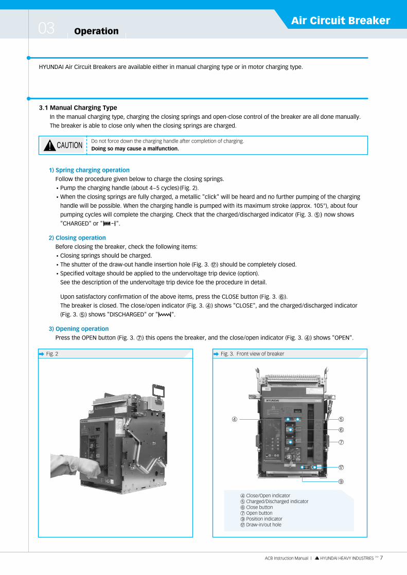
HYUNDAI Air Circuit Breakers are available either in manual charging type or in motor charging type.
ACB Instruction Manual | HYUNDAI HEAVY INDUSTRIES >> 7
Air Circuit BreakerOperation03
3.1 Manual Charging TypeIn the manual charging type, charging the closing springs and open-close control of the breaker are all done manually.
The breaker is able to close only when the closing springs are charged.
1) Spring charging operation
Follow the procedure given below to charge the closing springs.
�Pump the charging handle (about 4~5 cycles) (Fig. 2).
�When the closing springs are fully charged, a metallic "click" will be heard and no further pumping of the charging
handle will be possible. When the charging handle is pumped with its maximum stroke (approx. 105°), about four
pumping cycles will complete the charging. Check that the charged/discharged indicator (Fig. 3. ⑤) now shows
"CHARGED" or " ".
2) Closing operation
Before closing the breaker, check the following items:
�Closing springs should be charged.
�The shutter of the draw-out handle insertion hole (Fig. 3. �) should be completely closed.
�Specified voltage should be applied to the undervoltage trip device (option).
See the description of the undervoltage trip device foe the procedure in detail.
Upon satisfactory confirmation of the above items, press the CLOSE button (Fig. 3. ⑥).
The breaker is closed. The close/open indicator (Fig. 3. ④) shows "CLOSE", and the charged/discharged indicator
(Fig. 3. ⑤) shows "DISCHARGED" or " ".
3) Opening operation
Press the OPEN button (Fig. 3. ⑦) this opens the breaker, and the close/open indicator (Fig. 3. ④) shows "OPEN".
Do not force down the charging handle after completion of charging.Doing so may cause a malfunction.
� Fig. 3. Front view of breaker� Fig. 2
④
�
⑨
⑤
⑥
⑦
④ Close/Open indicator⑤ Charged/Discharged indicator⑥ Close button⑦ Open button⑨ Position indicator� Draw-in/out hole

Operation03
3.2 Motor Charging TypeIn this type, a motor-operated mechanism automatically charges the closing springs.
Means for remote electrical close-open control of the breaker are also fitted.
Complete manual operations are also possible for the same procedures described in above manual charging type
section.
1) Spring charging operation
�Supply the specified control power voltage to the charging motor circuit.
�In case of AC motor, check whether the UVT is applied to specified voltage.
�As soon as the closing springs are discharged, the charging motor is turned on to charge the closing springs.
�The charging motor is automatically stopped when the closing springs are fully charged, and the
charged/discharged indicator (Fig. 3. ⑤) shows "CHARGED" or " ".
While the charging time varies depending on the rated control voltage and the type of breaker, it is normally within
a range of 3 to 10 seconds.
2) Closing operation
Before closing the breaker, check the following items:
�Closing springs are charged.
�The shutter of the draw-out handle insertion hole (Fig. 3. �) is completely closed.
�Specified voltage is applied to the undervoltage trip device (option).
Upon satisfactory confirmation of the above items, press the CLOSE button.
This enegizes the latch release coil, which, in turn, releases the charged closing springs and the breaker is
immediately closed.
The spring charged indicator (Fig. 3. ⑤) shows "DISCHARGED" or " ".
With the closing springs discharged the charging motor is immediately turned to charge the closing spring.
3) Opening operation
The shunt trip device (SHT) or undervoltage trip device (UVT) is used for remote electrical opening operation.
Press the OPEN button. This opens the breaker via the SHT or UVT.
8 << ACB Instruction Manual | HYUNDAI HEAVY INDUSTRIES
�The permissible control voltage range foe the charging motor is 85 to 110% of the rated voltage.It is strongly recommended to supply the control power at the rated voltage.
�When dielectric withstand voltage test is carried out, the dielectric withstand voltage of motor for DC, AC110 and 220 V is 1500 V but for DC24 and 48 V is 500 V.
Even when item 2) is not satisfied, the breaker will not be placed in a closed state.Be sure to perform closing operation according item 2).
When close-open operations are repeated with the charging motor ON, limit the number of successive close-open cyclesto 10 times. If the open-close cycle is repeated more than 10 times, allow a cooling period of at least 10 minutes betweenthe 10th cycle and the 11th cycle.

The draw-out mechanism permits one to draw out and remove the breaker body from the draw-out cradle and to put the
breaker body back into the cradle, which facilitates the inspection and parts replacement.
The draw-out mechanism permits one to move the breaker body to any of the following three positions in the draw-out cradle.
The switchboard panel door can be shut with the breaker body drawn out to the TEST or ISOLATED position.
The auxiliary switch assembly mounted on the body works in the CONNECTED, TEST and ISOLATED position.
ACB Instruction Manual | HYUNDAI HEAVY INDUSTRIES >> 9
Air Circuit BreakerDraw-out Mechanism04
� Operational precautions????????????
W2@@@6X?g?7@@@@@1?g?@@@@@@@?g?@@@@@@@?g?3@@@@@5?g?V4@@@0Y?g?
????????
Open the breaker before working with the draw-out mechanism.????????????
W2@@@6X?g?7@@@@@1?g?@@@@@@@?g?@@@@@@@?g?3@@@@@5?g?V4@@@0Y?g?
????????
Be sure to loosen the screws of the fixing blocks (Fig. 1. � ) before drawing out the breaker body.If provided otherwise, a malfunction may occur.
????????????
W2@@@6X?g?7@@@@@1?g?@@@@@@@?g?@@@@@@@?g?3@@@@@5?g?V4@@@0Y?g?
????????
When you try to move the breaker body to the CONNECTED position, the operating force, will increase.Further rotate the draw-out handle to move the breaker body to the CONNECTED position.Typical operating force is about 25kgf.
????????????
W2@@@6X?g?7@@@@@1?g?@@@@@@@?g?@@@@@@@?g?3@@@@@5?g?V4@@@0Y?g?
????????
When the breaker is in connect position, stop turning the draw-out handle.Otherwise, a malfunction may occur.
????????????
W2@@@6X?g?7@@@@@1?g?@@@@@@@?g?@@@@@@@?g?3@@@@@5?g?V4@@@0Y?g?
????????
Make sure the draw-in/out hole (Fig. 1. � ) is closed after the draw-out handle is removed.Only at the exact position (ISOLATED, TEST, CONNECTED) the draw-in/out hole (Fig. 1. � ) can be closed.
� CONNECTED position � TEST position � ISOLATED position � REMOVED position
HiAN & HiAH type
Both the main and controlcircuit are connected fornormal service.
The main circuit isdisconnected and thecontrol circuit is connected.This position permitsoperation tests without theopening of the switchboardpanel door.
Both the main and controlcircuit are disconnected. The switchboard panel doorcan be closed.
The breaker body is competelyremoved from draw-out cradle.
� CONNECTED position � TEST position � ISOLATED position � REMOVED position
HiAS type
The main circuit isconnected and the controlcircuit is disconnected.After the connection ofcontrol circuit, electricaloperation is possible.
Both the main and controlcircuit are disconnected.After the connection ofcontrol circuit, electricaloperation tests without theopening of the switchboardpanel door are possible.
Both the main and controlcircuit are disconnected.After the connection ofcontrol circuit, electricaloperation is possible.
The breaker body is competelyremoved from draw-out cradle.

Draw-out Mechanism04
4.1 Moving the Breaker Body Within Draw-out Cradle (HiAN & HiAS06-32 Type)The draw-out handle (Fig. 4. ⑮) is used to move the breaker body to one of the three positions (CONNECTED, TEST and
ISOLATED) in the draw-out cradle. Attached draw-out handle (installed externally to the breaker) is to be used.
1) Moving to TEST position
�When the fixing blocks are fitted, loosen and free the right and left screws.
�Check that the breaker is OPEN. If it is CLOSED, press the OPEN button (Fig. 4. ⑦) to open the breaker.
�Press the OPEN button (Fig. 4. ⑦) and open the shutter of the draw-out handle insertion hole (Fig. 4. �)
at the same time.
�Engage the draw-out handle to the draw-out handle insertion hole and turn the handle counterclockwise to move
the breaker body. The position indicator moves to the test position.
10 << ACB Instruction Manual | HYUNDAI HEAVY INDUSTRIES
� Fig. 4
⑤ Charged/Discharged indicator⑦ Open button⑧ Draw-out dragger ⑨ Position indicator⑮ Draw-in/out handle� Draw-in/out hole� Fixing block
⑨ ⑨�
⑮�
When the fixing blocks (optional) are fitted, be sure to loosen the right and left screws of the fixing blocks beforedrawing out the breaker body.Otherwise, a malfunction may occur.
When the main circuit is seperated for drawing out, the breaker is occured to be pushed forward the front due tooperating spring of the main circuit contacts.A metallic "Click" will be heard, it varies the type of breaker. The breaker performance is not related the hoise.
When the draw-out handle is inserted in the draw-out mechanism shaft, the breaker is prevented from being closed. For close-open test, remove the draw-out handle and close the shutter of the draw-out handle insertion hole (Fig. 4. � ). If the shutter of insertion hole is not closed, it means ACB is on wrong position.The shutter of insertion hole should be closed by draw-out handle after correct position readjustment.
Injured human life.Keep the circuit breaker in the OPEN position when ACB insert to connect position.
⑦
⑤
⑦
⑤
��
⑮
⑧ ⑧

2) Moving to ISOLATED position
�The draw-out handle (Fig. 4. ⑮) turns counterclockwise to move from TEST to ISOLATED position.
3) Further withdrawal and removal of breaker body from ISOLATED position
The breaker body may be further drawn out from the ISOLATED position to remove it from the draw-out cradle for
inspection, maintenance or parts replacement purposes.
If the breaker is in charged condition, perform close-open operation once, and release the closing spring.
�Slowly draw out the breaker body from the draw-out cradle until the draw-out dragger stops (Fig. 4. ⑧)
�Lift the breaker body’s front part to release stopper and pull out again.
4.2 Putting the Breaker Body Back into Draw-out Cradle (HiAN & HiAS06-32 Type)Follow the procedure given below to put the removed breaker body back into the draw-out cradle.
�Check that the breaker is OPEN, then check that the position indicator (Fig. 4. ⑨) showing " ISOLATED".
�Check that the charged indicator (Fig. 4. ⑤) shows "DISCHARGED" or " " indicating the closing springs are
discharged.
�Lift up the breaker body or use a special lifter. Attach the body extention rail to roller of the cradle and push in the
breaker body slightly, as this time the body coil be stopped by stopper.
�To release the stopper, lift up the body's front part and push in again until the extention rails are locked.
This position is "ISOLATED".
�Press the OPEN button and to open the shutter of the draw-out handle insertion hole at the same time,
and engage the draw-out handle to draw-out handle insertion hole (Fig. 4. �).
�Turn the draw-out handle clockwise to send the breaker body into the draw-out cradle.
The position indicator (Fig. 4. ⑨) now shows "TEST".
Turn the draw-out handle clockwise to send the breaker into the CONNECTED position.
Mating of the primary disconnect device starts just before the CONNECTED position, and the draw-out handle will
become heavy, but continue to turn the handle. When the breaker is sent into the CONNECTED position, further turning
effort on the draw-out handle will be stopped.
The position indicator now shows "CONNECTED". Remove the draw-out handle (Fig. 4. ⑮).
�When the fixing blocks (Fig. 4. �) are fitted, fully tighten the right and left fixing screws using the draw-out handle.
ACB Instruction Manual | HYUNDAI HEAVY INDUSTRIES >> 11
Air Circuit Breaker
�Never enter under the breaker.The breaker weight will cause serious injuries in the event that it drops.
�This process should be performed slowly.�At this process, be sure to install crane or rope to breaker's body.
Never enter under the breaker.The breaker weight will cause serious injuries in the event that it drops.Do not force down the breaker body. It is caused damage of the breaker.
Do not force down when the draw-out handle can not be further turned.It is caused damage of draw-out mechanism.
Do not leave the breaker body as it is. When the above operation is made in as-received condition to separate the breaker body from the cradle, take necessary measures to prevent the possible turnover due to a change in the center of gravity.

Draw-out Mechanism04
12 << ACB Instruction Manual | HYUNDAI HEAVY INDUSTRIES
� Fig. 5
� Fig. 6
4.3 Operation of Draw-in/out Mechanism (HiAN40-63 & HiAH32 Type)The draw-out mechanism permits one to draw out and remove the breaker body from the draw-out cradle and to put
the breaker body back into the cradle, which facilitates the inspection and parts replacement. The draw-out mechanism
permits one to move the breaker body to any of the following three positions in the draw-out cradle. The switchboard
panel door can be shut with the breaker body drawn out to the CONNECTED or TEST or ISOLATED positions.
Operation precautions
�Open the breaker before working with the draw out mechanism.
�Be sure to loosen the screws of the fixing blocks if provided otherwise, a malfunction may occur.
�Please insert the draw-out handle (Fig. 9. ③) after the cover plate of handle insertion hole (Fig. 8. ②) comes down.
�When you try to move the breaker body to the CONNECTED position, the operating force will increase.
Further rotate the draw-out handle to move the breaker body to the CONNECTED position. Typical operating
force is about 25kgf.
�Be sure to close the handle cover plate, when the draw-out handle is drawn out.
- Incomplete position of the breaker body in the cradle shall make the breaker unclosed.
In this position, the main circuit and control circuits (of the breaker) are connected to the external circuits for normal service.
In this position, the main circuit is isolated, and the control circuits are connected. This position permits closed-open test, control circuit connected. This position permits closed-open test, control circuit.
In this position, the main circuit and control circuits are isolated. The breaker is completely de-energized in this position.
CONNECTED Position
TEST Position
ISOLATED Position
⑤ Charged/Discharged indicator⑦ Open button⑧ Draw-out dragger ⑨ Position indicator⑮ Draw-in/out handle� Draw-in/out hole� Fixing block
⑨ ⑨⑮
⑦
⑤
⑦
⑤
��
⑮
⑧
�
⑧
�
� ��

4.4 Draw-out Operation of ACB Body (HiAN40-63 & HiAH32 Type)The draw-out handle (Fig. 9. ③) is used to change the breaker position in the draw-out cradle.
1) Moving to TEST position
�(Fig. 7. ①) When the fixing blocks are fitted, loosen and free right and left screw.
�Check that the breaker is open, press the OPEN button (Fig. 8. ①) to open the breaker.
� Please insert the draw-out handle (Fig. 9. ③) after the cover plate of handle insertion hole (Fig. 8. ⑬) comes down.
� Turn the draw-out handle (Fig. 9. ③) counterclockwise to change CONNECTED position to TEST position after the
connection with draw out mechanism shaft in draw-out hole (Fig. 8. ③).
- When the breaker is on TEST position, the position indicator (Fig. 9. ③) points TEST.
ACB Instruction Manual | HYUNDAI HEAVY INDUSTRIES >> 13
Air Circuit Breaker
� Fig. 7
� Fig. 8
① ⑤ ② ③
① Fixing block(left, right)
④
� Fig. 9
①
②
③
① Position indicator② Front cover③ Draw-in/out handle
① Open button ② Handle cover plate ③ Draw-in/out hole④ Position indicator ⑤ Close/Open indicator
Draw-out Mechanism04
2) Moving to isolated position
�Turn counterclockwise the draw-out handle (Fig. 9. ③) to move from TEST to ISOLATE position.
- When located in the ISOLATED position, the position indicator (Fig. 9. ①) points ISOLATED.
3) Further withdrawal and removal of breaker body from ISOLATED position
The breaker body may be further drawn out from the ISOLATED position to remove it from the draw-out
cradle for inspection, maintenance or parts replacement purpose.
If the breaker is in charged condition, perform close-open operation once, and release the closing spring.
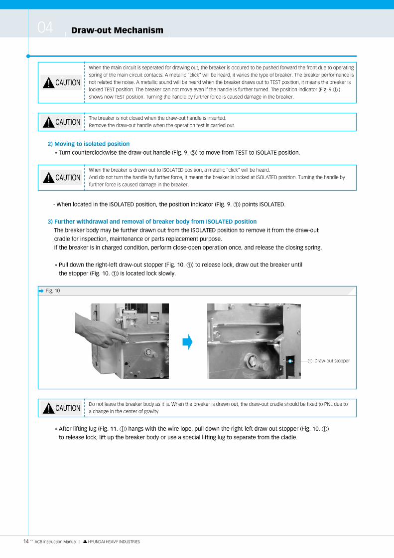
�Pull down the right-left draw-out stopper (Fig. 10. ①) to release lock, draw out the breaker until
the stopper (Fig. 10. ①) is located lock slowly.
�After lifting lug (Fig. 11. ①) hangs with the wire lope, pull down the right-left draw out stopper (Fig. 10. ①)
to release lock, lift up the breaker body or use a special lifting lug to separate from the cladle.
14 << ACB Instruction Manual | HYUNDAI HEAVY INDUSTRIES
When the main circuit is seperated for drawing out, the breaker is occured to be pushed forward the front due to operatingspring of the main circuit contacts. A metallic "click" will be heard, it varies the type of breaker. The breaker performance isnot related the noise. A metallic sound will be heard when the breaker draws out to TEST position, it means the breaker islocked TEST position. The breaker can not move even if the handle is further turned. The position indicator (Fig. 9. ① )shows now TEST position. Turning the handle by further force is caused damage in the breaker.
The breaker is not closed when the draw-out handle is inserted.Remove the draw-out handle when the operation test is carried out.
Do not leave the breaker body as it is. When the breaker is drawn out, the draw-out cradle should be fixed to PNL due toa change in the center of gravity.
When the breaker is drawn out to ISOLATED position, a metallic "click" will be heard.And do not turn the handle by further force, it means the breaker is locked at ISOLATED position. Turning the handle byfurther force is caused damage in the breaker.
� Fig. 10
① Draw-out stopper
�
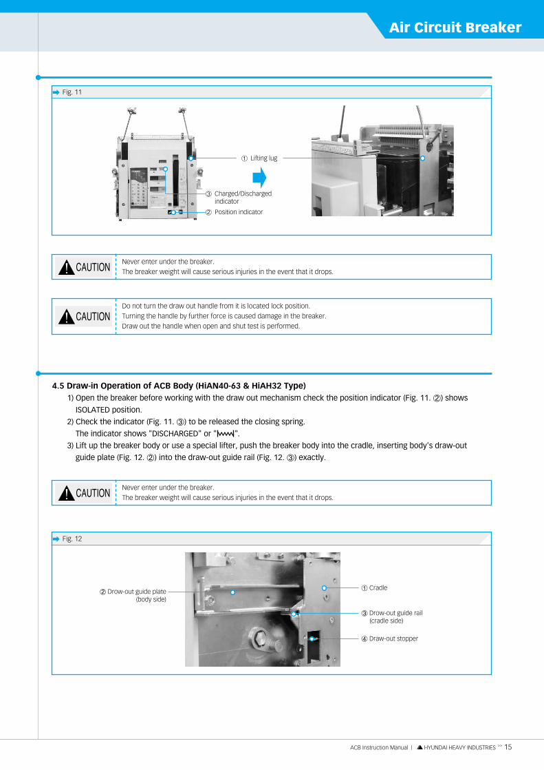
4.5 Draw-in Operation of ACB Body (HiAN40-63 & HiAH32 Type)1) Open the breaker before working with the draw out mechanism check the position indicator (Fig. 11. ②) shows
ISOLATED position.
2) Check the indicator (Fig. 11. ③) to be released the closing spring.
The indicator shows "DISCHARGED" or " ".
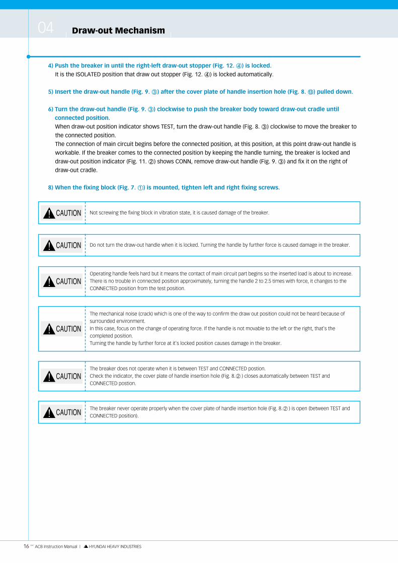
3) Lift up the breaker body or use a special lifter, push the breaker body into the cradle, inserting body's draw-out
guide plate (Fig. 12. ②) into the draw-out guide rail (Fig. 12. ③) exactly.
ACB Instruction Manual | HYUNDAI HEAVY INDUSTRIES >> 15
Air Circuit Breaker
Do not turn the draw out handle from it is located lock position.Turning the handle by further force is caused damage in the breaker.Draw out the handle when open and shut test is performed.
� Fig. 11
�① Lifting lug
� Fig. 12
① Cradle② Drow-out guide plate
(body side)
④ Draw-out stopper
③ Drow-out guide rail(cradle side)
Never enter under the breaker.The breaker weight will cause serious injuries in the event that it drops.
Never enter under the breaker.The breaker weight will cause serious injuries in the event that it drops.
② Position indicator
③ Charged/Dischargedindicator
Draw-out Mechanism04
4) Push the breaker in until the right-left draw-out stopper (Fig. 12. ④) is locked.
It is the ISOLATED position that draw out stopper (Fig. 12. ④) is locked automatically.
5) Insert the draw-out handle (Fig. 9. ③) after the cover plate of handle insertion hole (Fig. 8. ⑬) pulled down.
6) Turn the draw-out handle (Fig. 9. ③) clockwise to push the breaker body toward draw-out cradle until
connected position.
When draw-out position indicator shows TEST, turn the draw-out handle (Fig. 8. ③) clockwise to move the breaker to
the connected position.
The connection of main circuit begins before the connected position, at this position, at this point draw-out handle is
workable. If the breaker comes to the connected position by keeping the handle turning, the breaker is locked and
draw-out position indicator (Fig. 11. ②) shows CONN, remove draw-out handle (Fig. 9. ③) and fix it on the right of
draw-out cradle.
8) When the fixing block (Fig. 7. ①) is mounted, tighten left and right fixing screws.
16 << ACB Instruction Manual | HYUNDAI HEAVY INDUSTRIES
Do not turn the draw-out handle when it is locked. Turning the handle by further force is caused damage in the breaker.
Not screwing the fixing block in vibration state, it is caused damage of the breaker.
Operating handle feels hard but it means the contact of main circuit part begins so the inserted load is about to increase.There is no trouble in connected position approximately, turning the handle 2 to 2.5 times with force, it changes to theCONNECTED position from the test position.
The mechanical noise (crack) which is one of the way to confirm the draw out position could not be heard because ofsurrounded environment.In this case, focus on the change of operating force. If the handle is not movable to the left or the right, that's thecompleted position.Turning the handle by further force at it's locked position causes damage in the breaker.
The breaker does not operate when it is between TEST and CONNECTED postion.Check the indicator, the cover plate of handle insertion hole (Fig. 8. ② ) closes automatically between TEST and CONNECTED postion.
The breaker never operate properly when the cover plate of handle insertion hole (Fig. 8. ② ) is open (between TEST andCONNECTED position).
Frequency of periodic inspectionIt is the most appropriate that user works out his or her own inspection plan for breakers according to the switching
frequency, the values of normal making and breaking currents, the magnitude of fault current interrupted, service
conditions and environmental conditions.
Otherwise it is recommended to perform a simplified inspection once every 6 months and full inspection once a year.
Be sure to draw out the breaker to the ISOLATED position or to remove the breaker body from the draw-out cradle for
inspection or parts replacement purposes.
ACB Instruction Manual | HYUNDAI HEAVY INDUSTRIES >> 17
Air Circuit BreakerPeriodic Inspection and Parts Replacement05
Swithcing conditions of ACBInspection interval based on swithcing cycles
Switching operation in the stateof nearly no-carrying current
Switching operation in the ratedcurrent region
Swithcing operation in overloadregion (about 2-3 times the ratedcurrent)
Switching operation in currentinterruption region
1000
500
25
Each time
1000
500
25
Each time
1000
100
10
Each time
Over 3200 (A)1250~2500 frame (A)Below 630 frame (A)
Frequency of periodic inspectionWhile it is the most appropriate that user works out his or her own inspection plan for the breakers according to the
swithching frequency, the values of normal making and breaking currents, the magnitude of fault current interrupted,
service conditions and environmental conditions, it is recommended to perform a simplified inspection once every 6 months
and full inspection once a year.
Mechanical durability of the breakerThe following table shows the mechanical durability of the breaker in terms of the number of swithcing cycles. When the
breaker switching cycles exceed those shown in the table, the possibillity of failure may increase.
For renewal or thorought inspection of the breaker, contact HHI.
Frame size 2500 AF or smaller 3200 AF or smaller
NO. of switching cycles Over 5000 Over 3000
Be sure to draw out the breaker to the ISOLATED position or to remove the breaker body from the draw-out cradle forinspection or parts replacement purposes. Make sure that live parts have cooled down before performing inspection work.
Periodic Inspection and Parts Replacement05
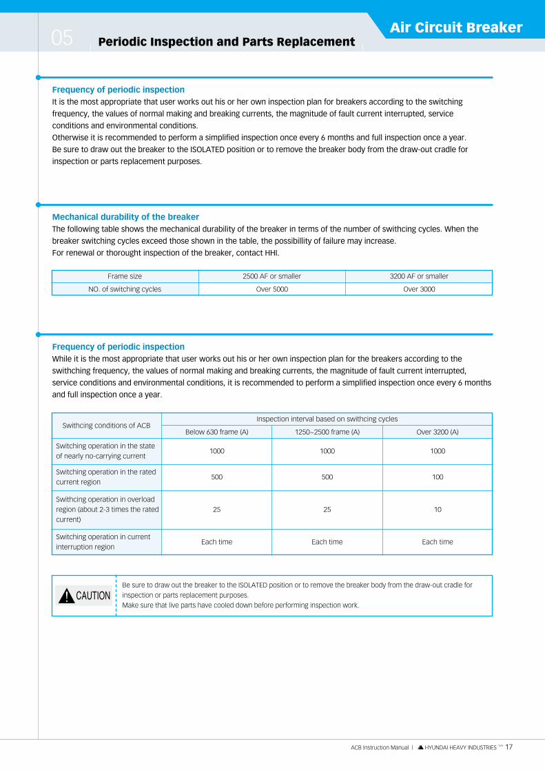
5.1 Arc ChamberCheck each arc chamber during the periodic inspection and also after a fault current was interrupted.
A cracked arc chamber cover or deionized grid side plate, or a heavy, hard-to-remove molten contact or deionized grid
pieces inside of the arc chamber, requires replacement of the arc chamber unit.
18 << ACB Instruction Manual | HYUNDAI HEAVY INDUSTRIES
� Fig. 14
1) Periodic inspection
2) Removal and mounting
Loosen the one-mounting screws captivated on an arc chamber until they are free, then remove the arc chamber &
nut. To mount the arc chamber, set nut & arc chamber in position and tighten the one-mounting screws.
Inspection item Method / Criteria
Dirt, Dust, Forenign matter
Cracks
Check visually. Inside must be clean, free of foreign matter and dust.Blow off foreign matter and dust with a jet of compressed air.
Check visually. There should be no cracks or other damage.Replace arc chamber if cracked or damaged.
� Fig. 13
Arc chambermounting screw
Nut
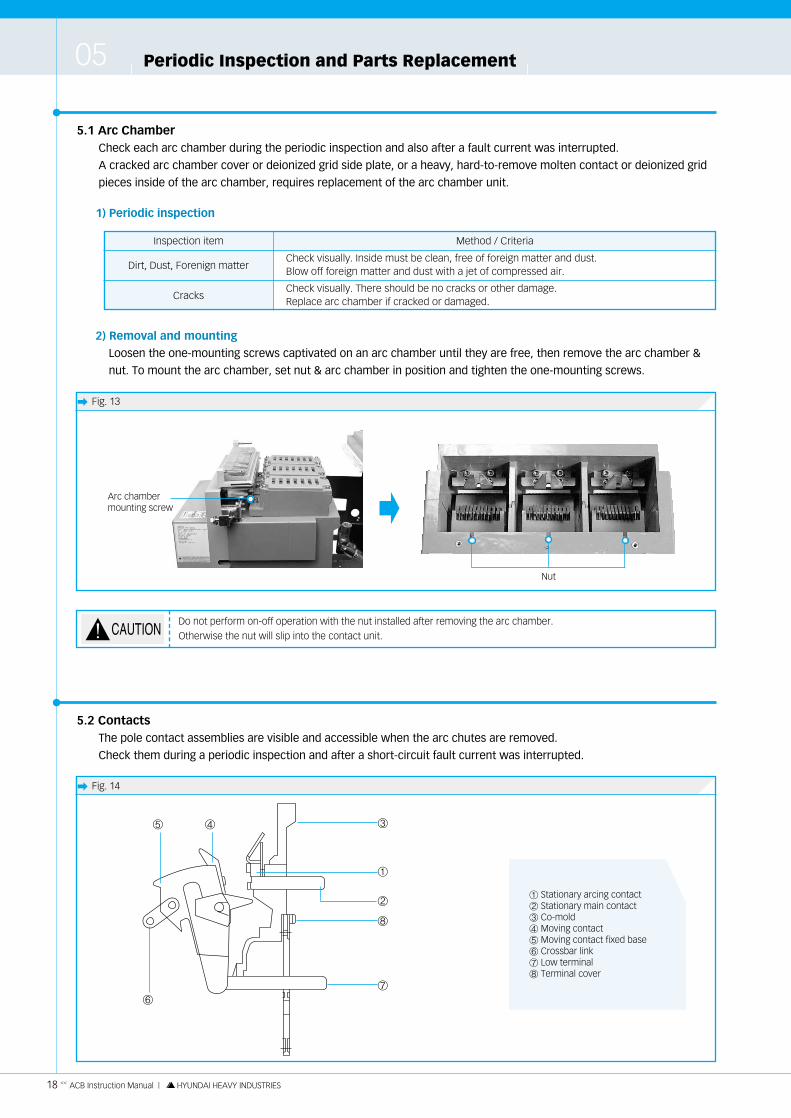
① Stationary arcing contact② Stationary main contact③ Co-mold④ Moving contact⑤ Moving contact fixed base⑥ Crossbar link⑦ Low terminal⑧ Terminal cover
①
②
⑧
⑦
⑥
⑤ ④ ③
5.2 ContactsThe pole contact assemblies are visible and accessible when the arc chutes are removed.
Check them during a periodic inspection and after a short-circuit fault current was interrupted.
�
Do not perform on-off operation with the nut installed after removing the arc chamber.Otherwise the nut will slip into the contact unit.

1) Periodic inspection
(1) Arcing contacts
ACB Instruction Manual | HYUNDAI HEAVY INDUSTRIES >> 19
Air Circuit Breaker
� Fig. 15
Inspection items Methods / Criteria
Contact tip surfaces
Mounting conditions
�Check visually.�Blackening of contact tip surfaces is due to oxidation and subformation.
and will not lead to any problems since it is wiped off in closing operation.�Remove dirt, dust, grease, etc.�Dress roughened surfaces with fine emery paper (# 200).
If thickness of contact tip is reduced to of original value after a number of dressing operations,replace both the moving and stationary arcing contacts.
�Check each moving arcing contact for loosenting of mounting bolts (Fig. 15. ③).�Check each contact tip pair for proper alignment in the closed position.
②
③
① Fixed arc chute② Stationary arcing contact③ Below 1600 A, over 2000 A 2-M6
①①③
(2) Main contacts
It the main contacts were toughened wear, clean their surfaces at the time of a periodic inspection.
2) Replacement
(1) Stationary arcing contact (see Fig.14)
�Remove the two mounting screws (Fig. 15. ③) and remove the stationary arcing contact (Fig. 15. ②).
�Set a new stationary arcing contact in position and firmly tighten the two mounting screws.
When contact tips, be careful not to let dust fall into the breaker mechanism.After cleaning, be sure to wipe and clean the tips.
At the time of removing or mounting, must not drop any washer into pole inside.

Periodic Inspection and Parts Replacement05
5.3 Operating Mechanism
20 << ACB Instruction Manual | HYUNDAI HEAVY INDUSTRIES
� Fig. 16
① Terminal spacer② Up terminal③ Low terminal④ Fixed arc chute⑤ Move cintact fix base⑥ Crossbar link⑦ Co-mold
⑧ CT⑨ Terminal cover⑩ Closing cam⑪ Close link unit⑫ Closing latch⑬ Co-trip latch unit⑭ Co-trip latch unit
⑮ Close/Open latch lever� Crossbar unit� Crossbar support� Closing spring� Co-latch� Charged/
Discharged indicator
� ⑬ ⑭
⑫
⑪
�
⑩
� � ⑥ ⑤
⑦
①
⑧
⑨
③
②
�
④⑮
Inspection items Methods / Criteria / Dispositions
Operation
Lubrication
Screws, bolts and springs
Dirt and dust
�Open and close the breaker through manual control to check the mechanical parts for normaloperation.
�Add a small amount of grease to each of the pins, shafts and their bearings.Avoid excessive oiling as such will result in accumulation of dirt and dust.
�Check screws and bolts on each part for signs of loosening. Tighten them if loose.�Check each spring for proper engagement and damage. Correct problem by repair or
replacement.
�Latching parts should be free of dirt and dust. Wipe them with a clean cloth.
1) Periodic maintenance
Check the operating mechanism in detail to a possible extent. If there are detail parts that seem to require a
check but are hard to check, please contact HHI.

5.4 Internal AccessoriesRemove the front cover (Fig. 1. ③) to gain access to the internal accessories.
To remove the front panel, remove the two front panel mounting screws.
ACB Instruction Manual | HYUNDAI HEAVY INDUSTRIES >> 21
Air Circuit Breaker
� Fig. 17. Location of internal accessories (motor charging type)
① LRC (Latch Release Coil)② MHT (Magnetic Hold Trigger)③ ACB protection relay④ Open lever for draw-out type⑤ Fixing blocks⑥ Shunt trip coil⑦ Charging motor
⑧ Draw-out shaft⑨ Close/Open indicator⑩ Charged/Discharged indicator⑪ Auxiliary switch unit⑫ Auxiliary switch fixing bolt⑬ Close button⑭ Open button
①
②
③
⑨
④
⑧
⑦
⑩
⑥
⑪
⑤
⑫
⑬⑭
Safety precautions:1) Do not place your finger or a tool in the gap between the CLOSE button and the close/open indicator
(Fig.17. ⑨, ⑬) since this gap is closed when the breaker is closed.2) Never attempt to put your hand or a tool into the breaker when the closing springs are charged.
Be sure to discharge the closing springs prior to internal inspection.
Periodic Inspection and Parts Replacement05
22 << ACB Instruction Manual | HYUNDAI HEAVY INDUSTRIES
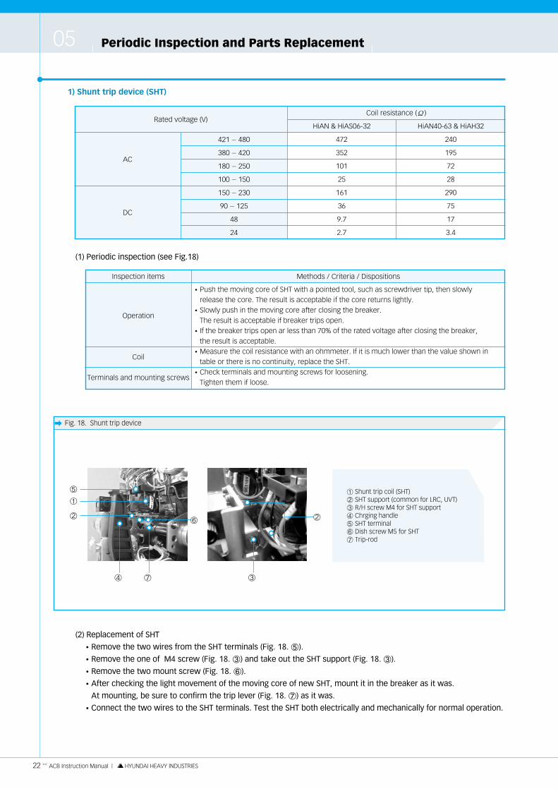
� Fig. 18. Shunt trip device
1) Shunt trip device (SHT)
Rated voltage (V)HiAN & HiAS06-32 HiAN40-63 & HiAH32
Coil resistance (Ω)
AC
DC
421 - 480
380 - 420
180 - 250
100 - 150
150 - 230
90 - 125
48
24
472
352
101
25
161
36
9.7
2.7
240
195
72
28
290
75
17
3.4
(1) Periodic inspection (see Fig.18)
Inspection items Methods / Criteria / Dispositions
Operation
Coil
Terminals and mounting screws
�Push the moving core of SHT with a pointed tool, such as screwdriver tip, then slowly release the core. The result is acceptable if the core returns lightly.
�Slowly push in the moving core after closing the breaker.The result is acceptable if breaker trips open.
�If the breaker trips open ar less than 70% of the rated voltage after closing the breaker, the result is acceptable.
�Measure the coil resistance with an ohmmeter. If it is much lower than the value shown intable or there is no continuity, replace the SHT.
�Check terminals and mounting screws for loosening.Tighten them if loose.
① Shunt trip coil (SHT)② SHT support (common for LRC, UVT)③ R/H screw M4 for SHT support④ Chrging handle⑤ SHT terminal⑥ Dish screw M5 for SHT⑦ Trip-rod
①
⑤
②
⑦④ ③
②⑥
(2) Replacement of SHT
�Remove the two wires from the SHT terminals (Fig. 18. ⑤).
�Remove the one of M4 screw (Fig. 18. ③) and take out the SHT support (Fig. 18. ③).
�Remove the two mount screw (Fig. 18. ⑥).
�After checking the light movement of the moving core of new SHT, mount it in the breaker as it was.
At mounting, be sure to confirm the trip lever (Fig. 18. ⑦) as it was.
�Connect the two wires to the SHT terminals. Test the SHT both electrically and mechanically for normal operation.

ACB Instruction Manual | HYUNDAI HEAVY INDUSTRIES >> 23
Air Circuit Breaker
2) Undervoltage trip device (UVT)
�The coil of undervoltage trip device (UVT) uses only DC rating.
�This undervoltage trip device includes instantaneous trip type IANS-U and time delay trip type IANS-T having 500 ms
and 1 sec time delay characteristics.
(1) General view of undervoltage trip device
(2) Periodic inspection
Inspection items Methods / Criteria / Dispositions
Operation
Coil resistance
Terminals and mounting screws
�The breaker is trip-free when the UVT is de-energized.
Because of this, when the PUSH TO CLOSE button is depressed, the closing springs are
discharged, but if the breaker is not closed, the result is acceptable.
�If the breaker can be closed at more than 85% of the rated voltage, the result is acceptable.
�If the breaker can be tripped at 70 to 35% of the rated voltage after closing breaker, the result
is acceptable.
�Measure the coil resistance with an ohmmeter.
If the measured resistance is much lower than
the value shown in the right or there is no
continuity, replace the UVT.
�Check terminals and mounting screws for loosening.
Retighten them if loose.
Rated voltage (V)
AC 100-470 VAC 100-200 V
Coil resistance (Ω)
160±16
(3) Replacement of UVT
When it is necessary to replace the UVT, replace the whole UVT unit.
�Remove the UVT coil and the wire terminal (Fig. 19. ①).
�Remove two UVT control device mounting bolt (Fig. 19. ③ 3-M6ⅹ10). Take out the UVT controller.
�Install UVT control device as it was on the breaker with UVT mounting screws.
�Connect the wire terminals with fasten terminals at the same time.
�Test the UVT both electrically and mechanically for normal operation in the same manner.
NEVER APPLY VOLTAGE TO THE UVT TERMINALS NOS."9" AND "10". WHEN THE UVT FUNCTION IS LOCKED.DOING SO MAY CAUSE BURN-OUT OF THE EQUIPMENT.
Never loosen nor tighten the ADJ nut. Doing so may cause a malfunction.
� Fig. 19. UVT Control device
① UVT wire terminals (fasten terminal)② UVT controller③ M6 bolt (4EA)
③
①
②

Periodic Inspection and Parts Replacement05
24 << ACB Instruction Manual | HYUNDAI HEAVY INDUSTRIES
� Fig. 20
① Yoke② Yoke mounting screw③ Moving core④ Coil⑤ Terminal
⑤
④
③
②
①
� Fig. 21
① LRC mounting bolt② Terminal
3) Latch release coil (LRC)
Coil resistance is the same as SHT
(1) General view of latch release device
(2) Periodic inspection
Inspection items Methods / Criteria / Dispositions
Operation
Coil resistance
Terminals and mounting screws
�Push the moving core with a pointed tool, such as screwdriver tip, then slowly release thecore. The result is acceptable if the core returns lightly.
�Charge the closing springs and push the moving core.The result is acceptable if the closing springs are discharged.
�If the breaker can be closed at 85% of the rated voltage, the result is acceptable.�Measure the coil resistance with an ohmmeter. If it were much lower than the value
shown in table 1 or there is no continuity, replace the LRC.�Check terminals and mounting screws for loosening.
Tighten them if they are loose.
(3) Replacement of LRC
�Remove the wires from the LRC terminals (Fig. 21. ②).
�Remove one M4 screw (Fig. 21. ①), and take out the LRC support from the breaker body.
�Remove LRC coil from LRC unit.
�After checking the light movement of the new LRC moving core (Fig. 20. ③), mount it in the breaker as it was.
�Connect the wires to the LRC terminals (Fig. 21. ②).
�Test the device both electrically and mechanically for normal operation in the same manner described
in periodic inspection tabel.
①
②

ACB Instruction Manual | HYUNDAI HEAVY INDUSTRIES >> 25
Air Circuit Breaker
� Fig. 23. Aux. SW connection diagram� Fig. 22. Auxiliary switch unit
AUX. SW SUP/A
Mounting bolt (2-M4×75L)
AUX. switch
4) Auxiliary switch unit
(1) General view of auxiliary switch, design of connection circuit
(2) Periodic inspection
Inspection items Methods / Criteria / Disposition
Operation
Coil resistance
Terminals and mounting screws
�Take the breaker body out of the draw-out cradle.�Connect the ohmmeter or alarm (buzzer) to each switch element.�Check that a-contact is ON and b-contact is OFF when breaker is CLOSED, and that a-contact
is OFF and b-contact is ON when breaker is OPEN.�Check each contact for surface roughness (removing lamminated phenolics plate from unit
permits a visual check of contacts).�If contact is excessively worn or rough, replace whole switch unit.
�Check terminals and mounting screws for loosening. Tighten them if loose.
� Fig. 24
5) Motor unit
(1) General view of motor unit
① Motor control unit mounting bolt② Charging motor③ Motor ratchet / M④ Motor ratchet spring⑤ Motor control unit
③④②
⑤
Check the replaced terminal numberl has been connected correctly, if provided otherwise a malfunction may occur.
(3) Replacement of auxiliary switch unit (see Fig. 17, 22)
The auxiliary switch unit is an assembly of 8 switch elements (4 a-contacts and 4 b-contacts). Replace the whole
switch unit even if a defect is partial.
�Remove the bolt (1-M6 wrench bolt) for assembly auxiliary switch (Fig.17. ⑫).
�Connect wires which taken out the terminal lug and terminal of new auxiliary switch unit.
�Fix it again as it was.
�Check the switch movement.
HiAN & HiAH type HiAS type
①

Periodic Inspection and Parts Replacement05
26 << ACB Instruction Manual | HYUNDAI HEAVY INDUSTRIES
� Fig. 25
6) Direction of ACB position padlock device
�Object : Position padlock device is designed for the process of locking position of ACB
(Isolated, Test or Connection position) by using shackle.
�Usage : At any position, after shutting the draw-out hole (Fig. 1. �), lock the shutter with shackle (Not offered).
(2) Operation check
Open and close the breaker through electrical control to check the relay for normal operation. Do this in the
following procedure.
- With the push-button switch ON, close the breaker.
- Immediately place the closed breaker in open condition. Even when the closing springs are "CHARGED".
if the breaker is not placed in re-closed condition, the result is acceptable. For resetting, turn the push-button
switch OFF.
(3) Replacement of motor control unit
�Open the ACB.
�Draw-out the body until isolated position.
�Release two mounting bolt (Fig. 25. ②).
�Take out motor unit.
�Release motor control unit mounting screws (Fig. 24. ①).
�Replace with new motor control unti and assemble it in reverse order.
�Check the operation by the (2) clause.
① Motor unit② Mounting bolts
①
②
Check the wires of terminal has been connected correctly, if provided otherwise a malfunction may occur.
Do not operate the draw-out handle during the running time.Since main circuit is alive, draw-out operation will cause fatal accident.

ACB Instruction Manual | HYUNDAI HEAVY INDUSTRIES >> 27
Air Circuit BreakerACB Protection Relay06
� Fig. 26. APR (ACB protection relay)
① Base current select dial ⑫ CPU malfunction indicator light (LED)② Long time delay trip pick-up current setting dial ⑬ Reset button③ Long time delay setting dial ⑭ Test switch (for short time delay and instantaneous)④ Short time delay trip pick-up current setting dial ⑮ Test switch (for long time delay)⑤ Short time delay setting dial � Pre-trip alarm current setting dial⑥ Instantaneous trip pick-up current setting dial � Pre-trip alarm time delay setting dial⑦ Ground fault trip pick-up current setting dial � INST / MCR tripped indicator light (LED)⑧ Pre-trip alarm pick-up indicator light (LED) � Ground fault trip time delay setting dial⑨ Long time delay tripped indicator light (LED) � INST / MCR select switch⑩ Short time delay / tripped indicator light (LED) � Test jack⑪ Ground fault Tripped indicator light (LED) � APR type
⑨⑧
①
�
⑪
⑫
�
③
⑤
�
�
�
⑮
⑭
⑩
②
④
⑥
�
⑦
⑬
�
ACB Protection Relay06
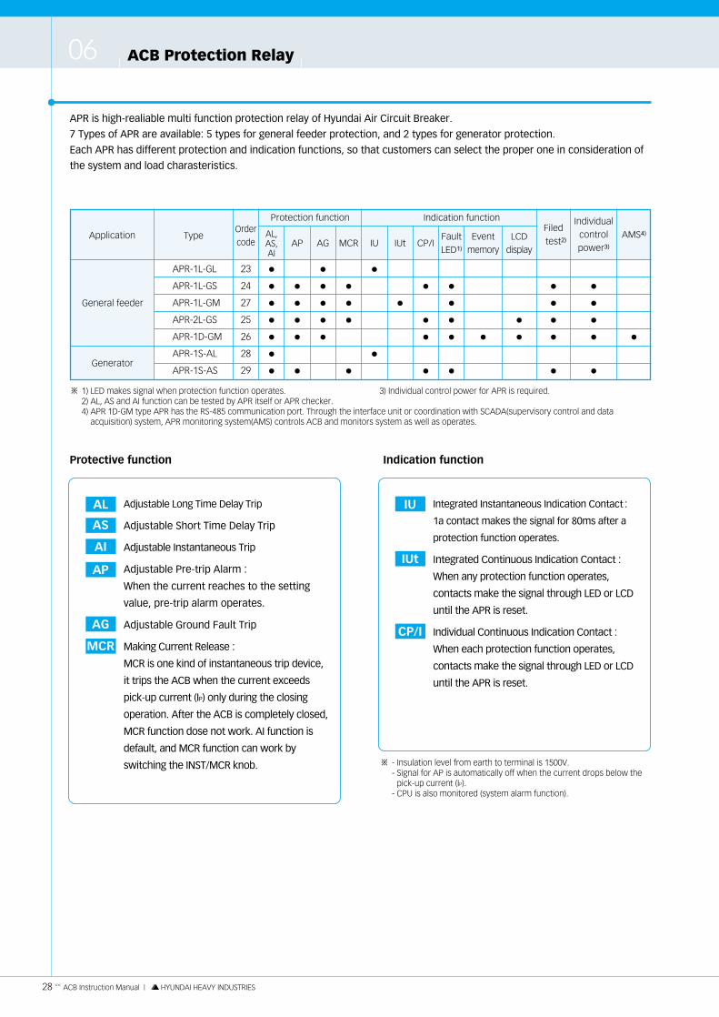
APR is high-realiable multi function protection relay of Hyundai Air Circuit Breaker.
7 Types of APR are available: 5 types for general feeder protection, and 2 types for generator protection.
Each APR has different protection and indication functions, so that customers can select the proper one in consideration of
the system and load charasteristics.
28 << ACB Instruction Manual | HYUNDAI HEAVY INDUSTRIES
AL Adjustable Long Time Delay Trip
AS Adjustable Short Time Delay Trip
AI Adjustable Instantaneous Trip
AP Adjustable Pre-trip Alarm :
When the current reaches to the setting
value, pre-trip alarm operates.
AG Adjustable Ground Fault Trip
MCR Making Current Release :
MCR is one kind of instantaneous trip device,
it trips the ACB when the current exceeds
pick-up current (IP) only during the closing
operation. After the ACB is completely closed,
MCR function dose not work. AI function is
default, and MCR function can work by
switching the INST/MCR knob.
Protective function Indication function
Application Type
Protection functionOrdercode
AL,AS,AI
AP AG MCR IU
Indication function
General feeder
Generator
APR-1L-GL
APR-1L-GS
APR-1L-GM
APR-2L-GS
APR-1D-GM
APR-1S-AL
APR-1S-AS
23
24
27
25
26
28
29
●
●
●
●
●
●
●
●
●
●
●
●
●
●
●
●
●
●
●
●
●
●
●
IUt
●
CP/I
●
●
●
●
FaultLED1)
Filedtest2)
Individualcontrol power3)
AMS4)
●
●
●
●
●
Eventmemory
●
LCDdisplay
●
●
●
●
●
●
●
●
●
●
●
●
●
1) LED makes signal when protection function operates. 3) Individual control power for APR is required.2) AL, AS and AI function can be tested by APR itself or APR checker.4) APR 1D-GM type APR has the RS-485 communication port. Through the interface unit or coordination with SCADA(supervisory control and data
acquisition) system, APR monitoring system(AMS) controls ACB and monitors system as well as operates.
- Insulation level from earth to terminal is 1500V.- Signal for AP is automatically off when the current drops below the
pick-up current (IP).- CPU is also monitored (system alarm function).
※
※
IU Integrated Instantaneous Indication Contact :
1a contact makes the signal for 80ms after a
protection function operates.
IUt Integrated Continuous Indication Contact :
When any protection function operates,
contacts make the signal through LED or LCD
until the APR is reset.
CP/I Individual Continuous Indication Contact :
When each protection function operates,
contacts make the signal through LED or LCD
until the APR is reset.
ACB Instruction Manual | HYUNDAI HEAVY INDUSTRIES >> 29
Air Circuit Breaker
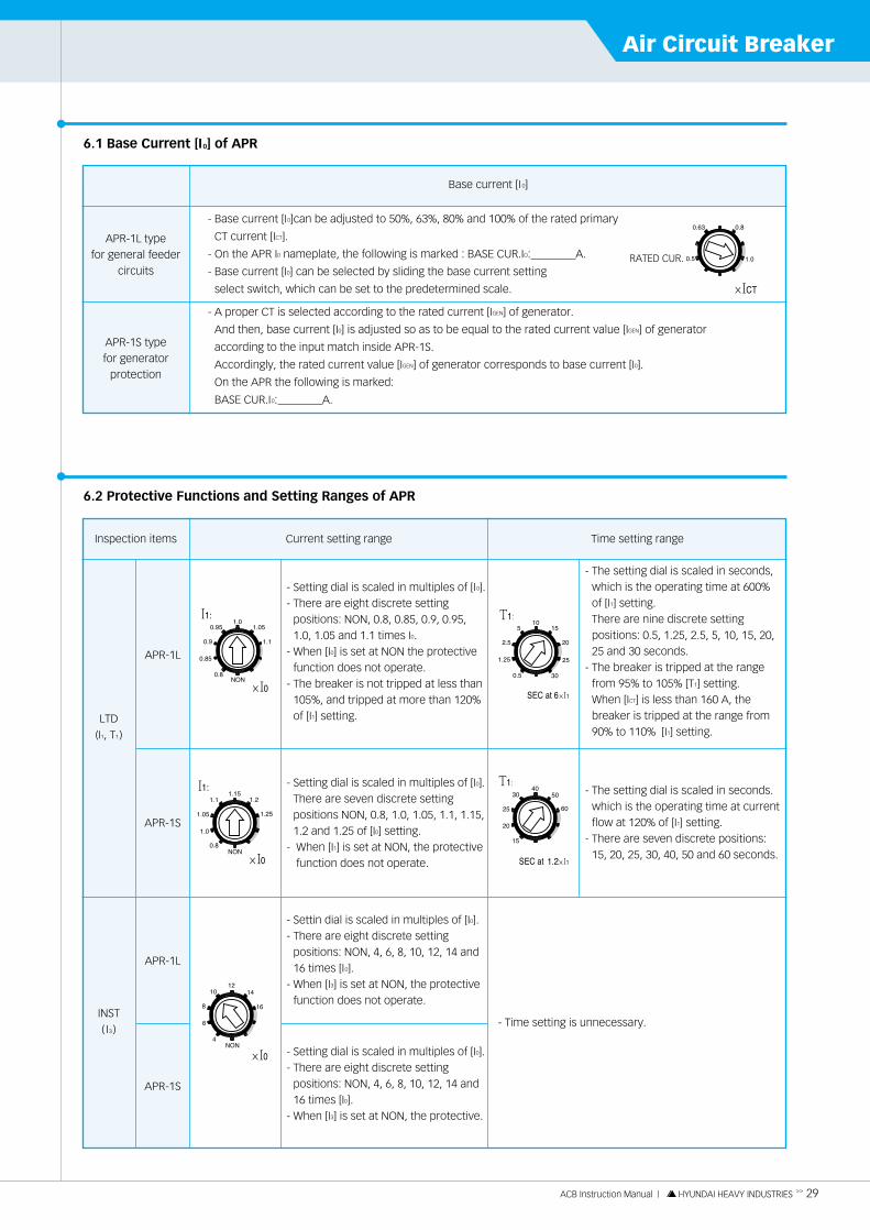
6.1 Base Current [I0] of APR
- A proper CT is selected according to the rated current [IGEN] of generator.
And then, base current [I0] is adjusted so as to be equal to the rated current value [IGEN] of generator
according to the input match inside APR-1S.
Accordingly, the rated current value [IGEN] of generator corresponds to base current [I0].
On the APR the following is marked:
BASE CUR.I0: A.
- Base current [I0]can be adjusted to 50%, 63%, 80% and 100% of the rated primary
CT current [ICT].
- On the APR I0 nameplate, the following is marked : BASE CUR.IO: A.
- Base current [I0] can be selected by sliding the base current setting
select switch, which can be set to the predetermined scale.
APR-1L typefor general feeder
circuits
APR-1S typefor generator
protection
Base current [I 0]
- Setting dial is scaled in multiples of [I0].- There are eight discrete setting
positions: NON, 0.8, 0.85, 0.9, 0.95,1.0, 1.05 and 1.1 times I0.
- When [I0] is set at NON the protectivefunction does not operate.
- The breaker is not tripped at less than105%, and tripped at more than 120%of [I1] setting.
- Setting dial is scaled in multiples of [I0].There are seven discrete settingpositions NON, 0.8, 1.0, 1.05, 1.1, 1.15,1.2 and 1.25 of [I0] setting.
- When [I1] is set at NON, the protectivefunction does not operate.
- Settin dial is scaled in multiples of [I0].- There are eight discrete setting
positions: NON, 4, 6, 8, 10, 12, 14 and16 times [I0].
- When [I3] is set at NON, the protectivefunction does not operate.
- Setting dial is scaled in multiples of [I0].- There are eight discrete setting
positions: NON, 4, 6, 8, 10, 12, 14 and16 times [I0].
- When [I3] is set at NON, the protective.
- The setting dial is scaled in seconds,which is the operating time at 600%of [I1] setting.There are nine discrete settingpositions: 0.5, 1.25, 2.5, 5, 10, 15, 20,25 and 30 seconds.
- The breaker is tripped at the rangefrom 95% to 105% [T1] setting. When [ICT] is less than 160 A, thebreaker is tripped at the range from90% to 110% [I1] setting.
- The setting dial is scaled in seconds.which is the operating time at currentflow at 120% of [I1] setting.
- There are seven discrete positions:15, 20, 25, 30, 40, 50 and 60 seconds.
- Time setting is unnecessary.
LTD(I1, T1)
INST( I3 )
APR-1L
APR-1S
APR-1L
APR-1S
Inspection items Current setting range Time setting range
6.2 Protective Functions and Setting Ranges of APR
RATED CUR.

ACB Protection Relay06
30 << ACB Instruction Manual | HYUNDAI HEAVY INDUSTRIES
- Setting dial is scaled in multiples of[I0]. There are eight discrete settingpositions: NON, 2, 2.5, 3, 4, 6, 8, 10times [I0]. When [I2] and [I3]are set at NON, thedevice is operated at 1000% of [I0]setting as a fail-safe function by [T2]setting.
- Setting dial is scaled in multiples of[I0]. There are nine discrete settingpositions: NON, 2, 2.5, 2.7, 3, 3.5, 4and 4.5, 5 times [I0].
- When [I2] is set at NON, the device isoperated at 500% of [I0] setting as afail-safe function.
- Setting dial is scaled in milliseconds,which is the operating time at currentflow higher than [I2] x 110% setting.There are seven discrete 80, 160,240, 320, 400, 480, 560 milliseconds.
- Setting dial is scaled in milliseconds,which is the operating time at currentflow higher than [I2] x 110% setting.
- There are seven discrete settingpositions: 80, 160, 240, 320, 400, 480,560 milliseconds.
STD(I2, T2)
APR-1L
APR-1S
Inspection item Current setting range Time setting range
- Setting dial is scaled in multiples ofOCR rated primarycurrent [ICT].
- Setting dial is scaled in multiples of[ICT].There are eight discrete settingpositions: NON, 0.1, 0.15, 0.2, 0.25,0.3, 0.35, 0.4 times [ICT].
- Setting dial is scaled in multiples of[IO].
- There are eight discrete positions:NON, 0.75, 0.8, 0.85, 0.9, 0.95, 1.0,1.05, and 1.1 times [IO].
- Setting dial is scaled in multiples of[IO].
- There are eight discrete positions:0.75, 0.8, 0.85, 0.9, 0.95, 1.0, 1.05,and 1.1 times [IO].
- Setting dial is scaled in milliseconds,which is the operating time at currentflow higher than [IG] x 120% setting.
- There are seven discrete 80, 160,240, 320, 400, 480, 560 milliseconds.
- There are nine discrete position atcurrent flow 120% of [IP]: 5, 10, 15, 20,25, 30, 35, 40, 45 seconds.
- Setting dial is scaled in second whichis the operating time at current flowhigher than [IP] setting.
- There are eight discrete 60, 80, 100,120, 140, 160, 180, 200 seconds(definite time delay).
GFT(IG)
Pre-alam(IP)
APR-1L
APR-1L
APR-1S
Inspection items Current setting range Time setting range

ACB Instruction Manual | HYUNDAI HEAVY INDUSTRIES >> 31
Air Circuit Breaker
�After adjustment, check the APR for proper setting by using a filed tester.
�Return the transparent cover (Fig. 27. ①) to its original position.
� Fig. 27
① APR transparent cover② � Screwdriver
①
② ①
Rotary step switches
Rotate the dial until the arrow points to the desired position.The setting is the same within the scale range denoted by a bold line.
Slide switches
Slide the switch knob up/down to turn ON/OFF.
Do not apply excessive force to the switches. The switches should lightly be turned or slid with the screwdriver.
1) Method of changing protective function settings
The settings of APR can be changed easily by dial operation.
This section describes the basic procedures for setting the protective device.
For setting details of individual protective functions see section 2.
(1) Basic procedures
�Press the side center of the transparent front cover to the left or right to release the latch, and remove the cover
from the breaker front cover.
�Using a small flat-head screwdriver, adjust the setting switches as appropriate. The APR has two types of setting
switches: rotary step switches and slide switches.

ACB Protection Relay06
32 << ACB Instruction Manual | HYUNDAI HEAVY INDUSTRIES
(2) The setting of SLIDE switch
�Frequency setting (50 Hz/60 Hz)
The frequency can change between 50 Hz and 60 Hz depending on power system. In case of APR set at 60 Hz in
50 Hz system, the tolerance of APR increases ±20% more than the exact setting.
�I²t ON/OFF
The STD trip timing can be changed between ramp ( I²t = C: inverse-time) mode and definite-time mode.
6.3 Functions of APR Operating IndicationThe function of operating indication includes IU contact for tripped indication (whole indication) and CP/I LED
light and contact for tripped indication.
1) IU contact for tripped indication (APR-1L-GL, APR-1S-AL)
�The contact output is one contact operating even when any one of LTD, STD, INST and GFT operates.
�The contact output is transmitted between the terminals � and � of disconnecting device for control circuit
(Fig. 1. ⑬).
�Rating of contact for tripped indication.
Rated voltage AC 250 V DC 30 V DC 125 V DC 250 V
Rated current (resistive load)
Rated current (inductive load)
8 A
3 A
5 A
3 A
0.5 A
0.25 A
0.3 A
0.15 A
� I2t ON/OFF
I²t ON : InverseI²t value becomes constant at 800% of setting current.Setting current tolerance is ± 30%
I²t OFF : Definite
�INST/MCR
Using the INST/MCR mode select switch enables the tripping mode to be changed between INST and MCR.
When changing the tripping mode to MCR, be sure to observe the following condition:
Estimated short-circuit fault current � Rated breaking capacity of the breaker (without INST).
※ MCR is a protective function which instantaneously trips open the breaker only when a fault current exceeding I3 is applied at making operation of the breaker.After making operation, MCR locks the INST trip function.
� INST/MCR
ACB Instruction Manual | HYUNDAI HEAVY INDUSTRIES >> 33
Air Circuit Breaker
2) CP/I LED light and contact for tripped indication
(APR-1L-GM, APR-1L-GS, APR-1D-GM, APR-2L-GS, APR-1S-AS)
�Control Power is required for tripped indication.
Supply the following power between terminals � and � of control circuit disconnecting device (Fig. 1. ⑫).
- AC 100 V to AC 125 V/5 VA or AC 200 V to AC 250 V/5 VA.
- DC 100 V to AC 125 V/5 W or DC 200 V to DC 250 V/5 W or DC 240 V/5 W.
�When LTD, STD or GFT operates, the LED lights for tripped indication (Fig. 26. ⑨, ⑩, �, ⑪) light up individually.
�At the same time, the contact signal ON is outputted individually between terminals �~� of control circuit
disconnecting device (Fig. 1. ⑫).
6.4 Field Test Method of APR Multifunction Protective Device Type
1) Function check method
�A simple check of operation for APR multifunction protective devices type can be made with a test switch.
�Function check of the ground fault trip function is not possible (But APR checker can check the ground fault trip function).
2) Control power and fitting for checking function
�Timer: a stopwatch.
�� screwdriver.
�Control power.
Operating indication terminal
�-� : Pre-alarm terminal �-� : LTD/STD/INST terminal�-� : GFT terminal
For function check of each protective function, draw out the breaker to the ISOLATED position, or take it out from thedraw-out cradle. If making function check in the TEST position, confirm that there is no influence on the sequence.
�The LTD, STD and GFT tripped indications remain ON until the reset button (Fig. 26. ⑬ ) is depressed or the control
power is turned OFF. Press the reset button or turn the control power OFF for more than one second resets the
ON state.
�LED light and contacts for pre-trip alarm operation indication.
- The LTD pickup indication LED light (Fig. 26. ⑧ ) flickers at more than pickup current value [IP].
At the same time, the contact signal ON is outputted between terminals �~� of control circuit disconnecting
device (Fig. 1. ⑫ ).
- The operation indication is automatically reset if the current of less than [IP] is reached.
�CPU malfunction indicating LED lights and contact .
When the analog circuit is abnormal, CPU malfunction indicating LED light (Fig. 26. ⑫ ) lights up.
If CPU malfunction indicating LED light lights up, the breaker in service is not effected directly.
But take the following measures at earlier stages and eliminate the trouble.
※ Press the reset button (Fig. 26. ⑬ )
If the abnormality is temporary, such as noise, the LED will go off, At that time, the control function returns to normal.
If the LED does not go off even by pushing the reset button, some abnormality may occur. In this case, immediately contact with HHI.
�Rating of contact for trip indication.
Rated voltage AC 250 V DC 220 V
Rated current (resistive load)
Rated current (inductive load)
125 VA (max. 2 A)
20 VA (max. 2 A)
60 W (max. 2 A)
10 W (max. 2 A)

ACB Protection Relay06
34 << ACB Instruction Manual | HYUNDAI HEAVY INDUSTRIES
3) Function check method of each protective function
3. Push the test switch (Fig. 26. ⑮) "LOW" (current flow of 6 times the base current [IO]
in type APR-1L, and 1.5 times the base current in type APR-1S), and at the same time, start the tripping time
measurement with a watch.
Also hold the test switch until the breaker is tripped.
4. After tripping, release the test switch. It is reset to OFF (neutral) automatically.
5. Read the tripped time.
If it is nearly equal to the operation time at the current flow of 6 times [IO] for type
APR 1L and 1.5 times [IO] for type APR-1S, it is normal.
6. Return the INST pick-up current setting dial to the original set value with a � screwdriver.
1. Close the breaker.
2. In case of APR-1L type, if the setting current of STD/INST pick-up less than 6 times of base current,
set the dial I2, I3 to the NON position with a � screwdriver.
1. Close the breaker.
2. Push the test switch (Fig. 26. ⑭) to "HI" current flow of more than 16 times the base current [IO].
If the breaker is tripped momentarily, it is normal.
3. After tripping, release the test switch. It is reset to OFF (neutral) automatically.
Long time delay trip
function check
Short time delay trip
function check
Instataneous timedelay trip function
check
Protective function APR-1L (for general feeder circuit) / APR-1S (for generator protection)
1. Close the breaker.
2. Set the INST pickup current setting dial to NON, using a � screwdriver.
3. Push the test switch (Fig. 26. ⑭) to "HI" current flow of more than 16 times the base current [IO]. If the
breaker is tripped with time delay setting, it is normal.
4. After tripping, release the test switch.
5. Return the INST pickup current setting dial to the original set value with a � screwdriver.
ACB Instruction Manual | HYUNDAI HEAVY INDUSTRIES >> 35
Air Circuit Breaker
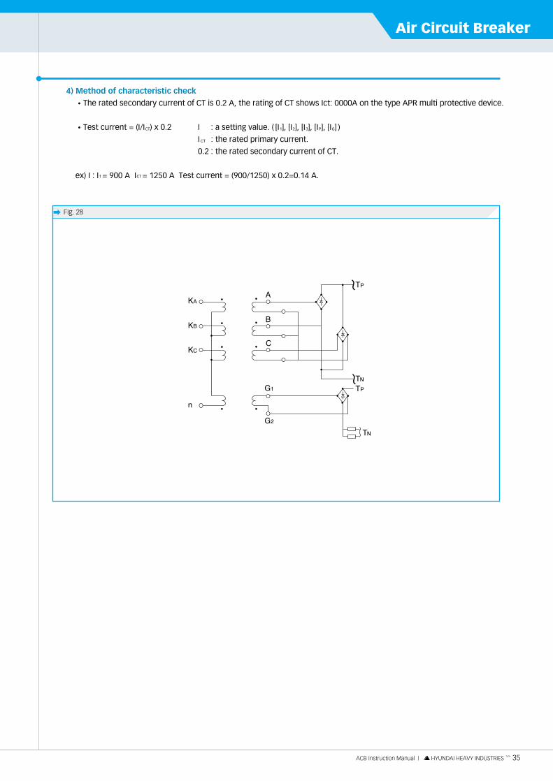
4) Method of characteristic check
�The rated secondary current of CT is 0.2 A, the rating of CT shows Ict: 0000A on the type APR multi protective device.
�Test current = (I/ICT) x 0.2 I : a setting value. ( [I1], [I2], [I3], [IP], [IG] )
I CT : the rated primary current.
0.2 : the rated secondary current of CT.
ex) I : I1 = 900 A ICT = 1250 A Test current = (900/1250) x 0.2=0.14 A.
� Fig. 28

ACB Protection Relay06
36 << ACB Instruction Manual | HYUNDAI HEAVY INDUSTRIES
� Fig. 29
Item Rate or indication
Control voltage
Usable temperature
Test range of operation time
Test current range
Dimension (mm)
AC 220 V±10 V
0℃~45℃
0 ms~999.999 sec
0~3400 mA
W 220 x H 90 x D 150
6.5 APR Function Check Method by APR Checker
1) Configuration and specifications of APR checker
⑧
⑤
④
⑥ ⑦
⑨
⑩
①
②
③
2) Manual
�Caution and preparation for every test
- Connect the jack ⑩ to the test terminal of the APR before the test.
- Select the test phase with the switch ⑤.
- Select the pick-up or the TIME function with the switch ⑦.
- Select the test item of the APR with the switch ⑥.
- Turn on the power switch ②.
- Set the test current in the left side of the checker with the switch ⑧, ⑨.
- The LCD ① will display the current as 2000 mA in the first line and the time as 999.999 sec in the second line.
The current can be 0~3400 mA according to test current, and the time can be 0~999.999 sec according to
operation time.
�Pre-alarm pick-up
- Select the pick-up function with the switch ⑦.
- Select the PTA function with the switch ⑥.
- Push the INPUT button ③.
- Check the pre-alarm condition of the APR during adjusting the current with the switch ⑧, ⑨.
�Pre-alarm time
- Select the TIME function with the switch ⑦.
- Select the PAT function with the switch ⑥.
- Set the test current by adjusting the switch ⑧, ⑨, while the current is (being) varied with the VR ⑧, ⑨.
- Push the INPUT button ③.
- When the pre-alam of the APR works, the operation time will stop.
- Push the RESET button ④ after the test.

ACB Instruction Manual | HYUNDAI HEAVY INDUSTRIES >> 37
Air Circuit Breaker
�LTD pick-up
- Select the pick-up function with the switch ⑦.
- Select the LTD function with the switch ⑥.
- Push the INPUT button ③.
- Check the LTD pick-up condition of the APR during adjusting the current with the switch ⑧, ⑨.
�LTD time delay
- Select the TIME function with the switch ⑦.
- Select the LTD function with the switch ⑥.
- Set the test current by adjusting the switch ⑧, ⑨.
- Push the INPUT button ③.
- When the APR is tripped, the operation time will stop.
- Push the RESET button ④ after the test.
�STD pick-up
- Select the pick-up function with the switch ⑦.
- Select the STD function with the switch ⑥.
- Push the INPUT button ③.
- Check ths STD pick-up condition of the APR during adjusting the current with the switch ⑧, ⑨.
�STD time delay
- Select the TIME function with the switch ⑦.
- Select the STD function with the switch ⑥.
- Set the test current by adjusting the current with the switch ⑧, ⑨.
- Push the INPUT button ③.
- When the APR is tripped, the operation time will stop.
- Push the RESET button ④ after the test.
�INST pick-up
- Select the pick-up function with the switch ⑦.
- Select the INST function with the switch ⑥.
- Push the INPUT button ③.
- Check ths INST pick-up condition of the APR during adjusting the current with the switch ⑧, ⑨.
�Ground fault pick-up
- Select the pick-up function with the switch ⑦.
- Select the GFT function with the switch ⑥.
- Push the INPUT button ③.
- Check ths GFT pick-up condition of the APR during adjusting the current with the switch ⑧, ⑨.
�Ground fault time delay
- Select the TIME function with the switch ⑦.
- Select the GFT function with the switch ⑥.
- Set the test current by adjusting the current with the switch ⑧, ⑨.
- Push the INPUT button ③.
- When the APR is tripped, the operation time will stop.
- Push the RESET button ④ after the test.
ACB Protection Relay06
38 << ACB Instruction Manual | HYUNDAI HEAVY INDUSTRIES
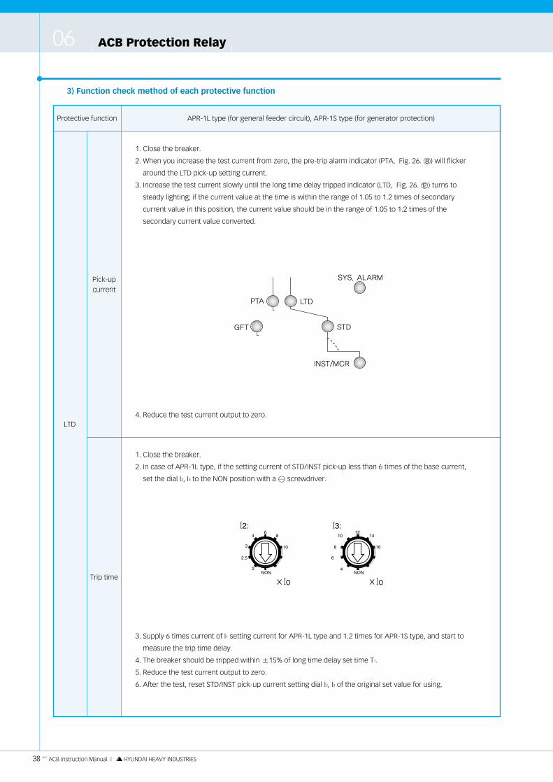
3) Function check method of each protective function
1. Close the breaker.
2. When you increase the test current from zero, the pre-trip alarm indicator (PTA, Fig. 26. ⑧) will flicker
around the LTD pick-up setting current.
3. Increase the test current slowly until the long time delay tripped indicator (LTD, Fig. 26. ⑫) turns to
steady lighting; if the current value at the time is within the range of 1.05 to 1.2 times of secondary
current value in this position, the current value should be in the range of 1.05 to 1.2 times of the
secondary current value converted.
4. Reduce the test current output to zero.LTD
Pick-upcurrent
Trip time
Protective function APR-1L type (for general feeder circuit), APR-1S type (for generator protection)
1. Close the breaker.
2. In case of APR-1L type, if the setting current of STD/INST pick-up less than 6 times of the base current,
set the dial I2, I3 to the NON position with a � screwdriver.
3. Supply 6 times current of I1 setting current for APR-1L type and 1.2 times for APR-1S type, and start to
measure the trip time delay.
4. The breaker should be tripped within ±15% of long time delay set time T1.
5. Reduce the test current output to zero.
6. After the test, reset STD/INST pick-up current setting dial I2, I3 of the original set value for using.
ACB Instruction Manual | HYUNDAI HEAVY INDUSTRIES >> 39
Air Circuit Breaker
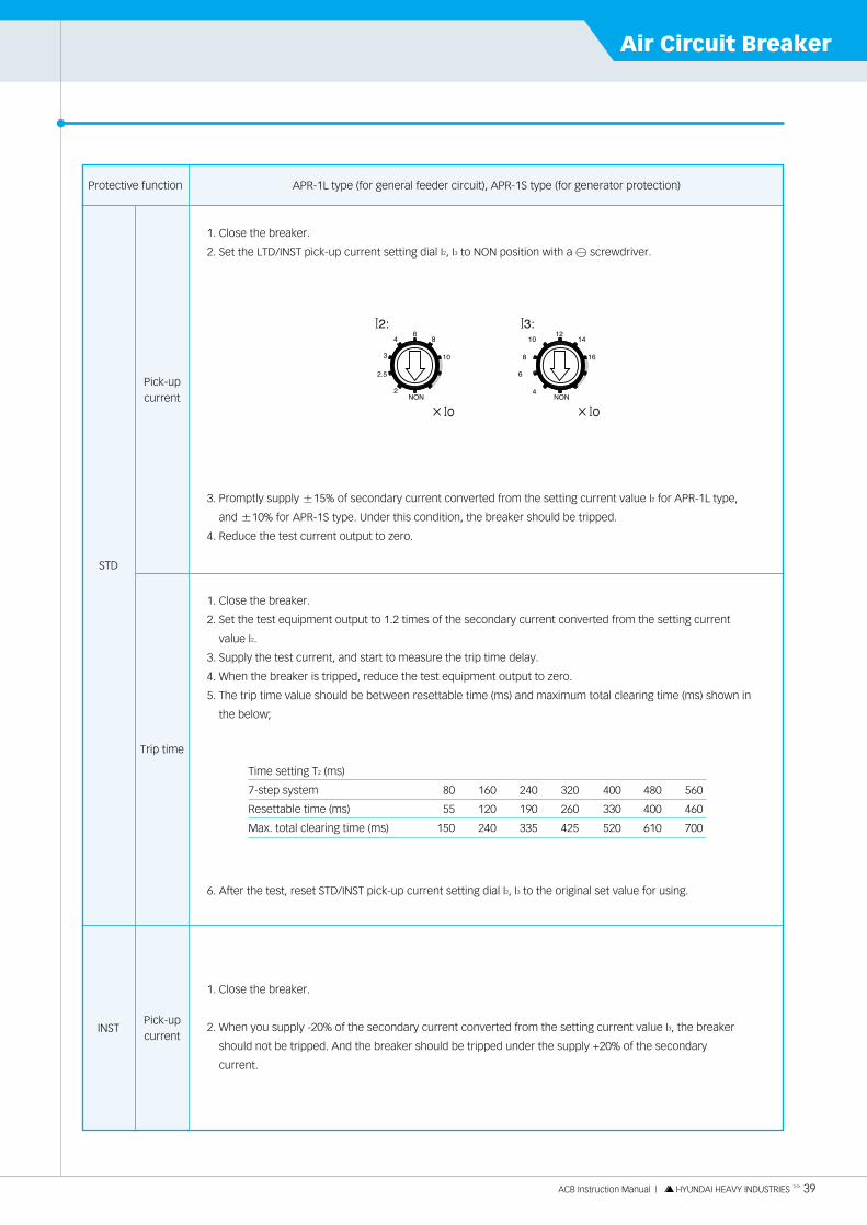
1. Close the breaker.
2. Set the LTD/INST pick-up current setting dial I2, I3 to NON position with a � screwdriver.
3. Promptly supply ±15% of secondary current converted from the setting current value I2 for APR-1L type,
and ±10% for APR-1S type. Under this condition, the breaker should be tripped.
4. Reduce the test current output to zero.
STD
INST
Pick-upcurrent
Trip time
Pick-upcurrent
Protective function APR-1L type (for general feeder circuit), APR-1S type (for generator protection)
1. Close the breaker.
2. Set the test equipment output to 1.2 times of the secondary current converted from the setting current
value I2.
3. Supply the test current, and start to measure the trip time delay.
4. When the breaker is tripped, reduce the test equipment output to zero.
5. The trip time value should be between resettable time (ms) and maximum total clearing time (ms) shown in
the below;
Time setting T2 (ms)
7-step system 80 160 240 320 400 480 560
Resettable time (ms) 55 120 190 260 330 400 460
Max. total clearing time (ms) 150 240 335 425 520 610 700
6. After the test, reset STD/INST pick-up current setting dial I2, I3 to the original set value for using.
1. Close the breaker.
2. When you supply -20% of the secondary current converted from the setting current value I3, the breaker
should not be tripped. And the breaker should be tripped under the supply +20% of the secondary
current.

ACB Protection Relay06
40 << ACB Instruction Manual | HYUNDAI HEAVY INDUSTRIES
1. Close the breaker.
2. Increase the test current until the pre-trip alarm pick-up indicator (PTA, Fig. 26. ⑧) flickers: In this
position the current value should be in the range of ±7.5% of secondary current value converted from
the setting current value IP for APR-1L type and ±5% for APR-1S type.
3. Reduce the test current output to zero.
Pre tripalarm
GFT
Pick-up current
Trip time
Tripcurrent
Trip time
Protective function APR-1L type (for general feeder circuit), APR-1S type (for generator protection)
1. Supply the specified control power.
2. Supply 1.1 times of the secondary current converted from the setting current value IP for APR-1L type,
and 1.2 times for APR-1S type, and start to measure the pre-trip alarm time. The time balance between
Ac and Ap terminal should be in the range of ±20% of the setting time value TP for APR-1S type and
±15% for APR-1S type.
3. Reduce the test current output to zero.
1. Close the breaker.
2. Set the test equipment output to 1.20% of the secondary current converted from the setting current value IG.
3. Supply the test current, and start to measure the trip time. At the same time, start the trip time
measurement with a watch.
4. When the breaker is tripped, reduce the test equiment output to zero.
5. The trip time value should be between resettable time (ms) and maximum total clearing time (ms)
shown the below;
Time setting TG (ms)
7-step system 80 160 240 320 400 480 560
Resettable time (ms) 55 120 190 260 330 400 460
Max. total clearing time (ms) 150 240 335 425 520 610 700
1. Close the breaker.
2. When you supply of ±20% of secondary current converted from the setting current [IG], the breaker should be
tripped.
3. Reduce the test current output to zero.
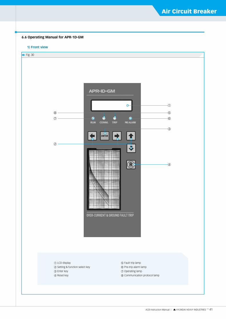
ACB Instruction Manual | HYUNDAI HEAVY INDUSTRIES >> 41
Air Circuit Breaker
6.6 Operating Manual for APR-1D-GM
1) Front view
� Fig. 30
① LCD display
② Setting & function select key
③ Enter key
④ Reset key
⑤ Fault trip lamp
⑥ Pre-trip alarm lamp
⑦ Operating lamp
⑧ Communication protocol lamp
⑦
⑧
⑥
①
③
⑤
④
②

ACB Protection Relay06
42 << ACB Instruction Manual | HYUNDAI HEAVY INDUSTRIES
■ APR-1D-GM Menual

ACB Instruction Manual | HYUNDAI HEAVY INDUSTRIES >> 43
Air Circuit Breaker

ACB Protection Relay06
44 << ACB Instruction Manual | HYUNDAI HEAVY INDUSTRIES
2) Key menu structure
� Display screen
� Fault
� Set screen
� Sys
� Test
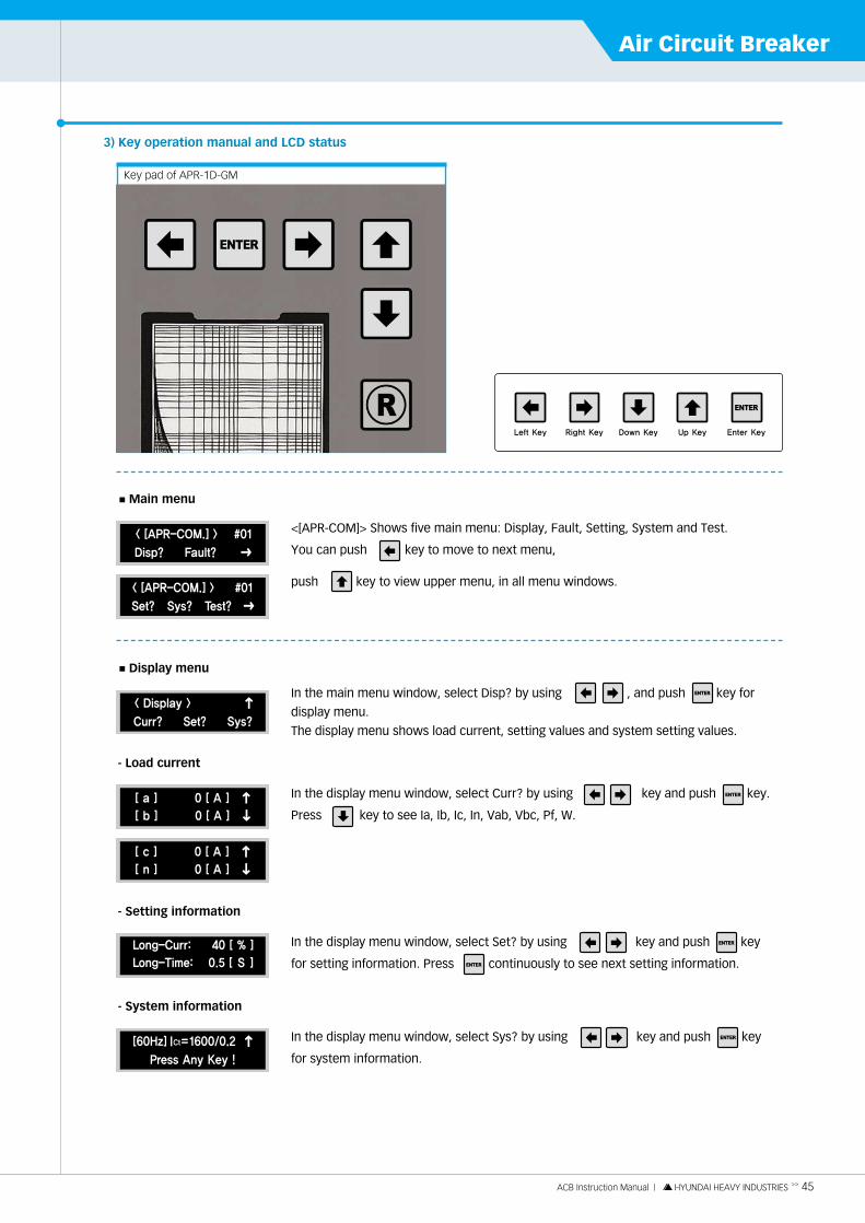
ACB Instruction Manual | HYUNDAI HEAVY INDUSTRIES >> 45
Air Circuit Breaker
3) Key operation manual and LCD status
push key to view upper menu, in all menu windows.
<[APR-COM]> Shows five main menu: Display, Fault, Setting, System and Test.
You can push key to move to next menu,
■ Main menu
Key pad of APR-1D-GM
In the display menu window, select Curr? by using key and push key.
Press key to see Ia, Ib, Ic, In, Vab, Vbc, Pf, W.
- Load current
In the main menu window, select Disp? by using , and push key for
display menu.
The display menu shows load current, setting values and system setting values.
■ Display menu
In the display menu window, select Set? by using key and push key
for setting information. Press continuously to see next setting information.
- Setting information
In the display menu window, select Sys? by using key and push key
for system information.
- System information

ACB Protection Relay06
46 << ACB Instruction Manual | HYUNDAI HEAVY INDUSTRIES
Press key to see fault trip history.
In the main menu window, select Fault? by using key, and push key
for trip information.
■ Fault menu
In the main menu window, select Set? by using key and push for
setting menu.
Through the pass word check, you can approach setting menu.
■ Setting menu
In the setting menu window, each item has follow meaning.
LTD curr: I1, LTD time: T1
STD curr: I2, STD time: T2, INST curr: I3, GFT curr:Ig, GFT time: Tg,
PRE-ALARM Curr: Ip, PRE-ALARM time: Tp
※ Pass word check method if password is 1234, change the flicker "O" into "4" by using key.
You can move to next "O" by using key, and set the other digits.
Move cursor to the figure required modification by using key. Set "4" and
"O" by using key, and push key. Then, the below screen will appear.
You can select "Y" to finish the setting or "N" to cancel the setting, and push key.
Set the other values with same method.
If you want to set I1=40%, select I1 by using key and push key, you can see the below window.
In the main menu window, select Sys? by using key and push key.
Through the password check, you can approach system menu.
In the system menu window, user can set the communication port, password,
CT ratio, Hz, load type and the characteristic curve of overload.
■ System menu
Make new figure by using key, and push key, the below screen
will appear. Select "Y" or "N" and push key.
Set other values with same method.
If you want to set communication address, select Add? by using key, and push key, and you can see
below window.
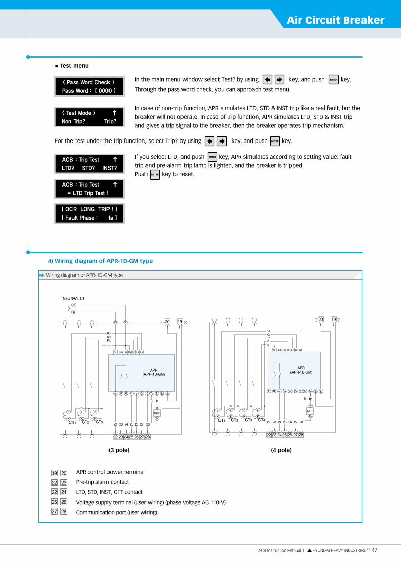
ACB Instruction Manual | HYUNDAI HEAVY INDUSTRIES >> 47
Air Circuit Breaker
In case of non-trip function, APR simulates LTD, STD & INST trip like a real fault, but the
breaker will not operate. In case of trip function, APR simulates LTD, STD & INST trip
and gives a trip signal to the breaker, then the breaker operates trip mechanism.
In the main menu window select Test? by using key, and push key.
Through the pass word check, you can approach test menu.
■ Test menu
If you select LTD, and push key, APR simulates according to setting value: fault
trip and pre-alarm trip lamp is lighted, and the breaker is tripped.
Push key to reset.
For the test under the trip function, select Trip? by using key, and push key.
4) Wiring diagram of APR-1D-GM type
� Wiring diagram of APR-1D-GM type
Rn Sn Tn KC KB KARn Sn Tn KC KB KA
APR control power terminal
Pre-trip alarm contact
LTD, STD, INST, GFT contact
Voltage supply terminal (user wiring) (phase voltage AC 110 V)
Communication port (user wiring)
19
22
22
25
27
20
23
24
26
28
(3 pole) (4 pole)
ACB Protection Relay06
48 << ACB Instruction Manual | HYUNDAI HEAVY INDUSTRIES
5) General directions for the current test of main circuit
When a single-phase current source is used to test the breaker, observe the following directions.
�Temperature test
If a single-phase test current equal to the rated current is applied to a breaker with its three poles connected in series
for temperature test, the breaker will be tripped. All function (LTD, STD, INST, GFT) of APR set "NON" for a single
phase test.
�Over current trip test
When a trip test is performed on a breaker with a test current supplied to its main circuit, in the same manner
as in the temperature test, do this for each pole so that 2 out of the three poles are not in the same direction
(not allowed when ground fault trip is provided) or with 2 poles.

ACB Instruction Manual | HYUNDAI HEAVY INDUSTRIES >> 49
Air Circuit BreakerInsulation Resistance Test and Dielectric Withstand Test
7.1 Main Circuit
�Dielectric withstand voltage test: AC 3500 V for one minute.
�Insulation resistance test: DC 500 V insulation resistance tester (megger).
The insulation resistance test and dielectric withstand test of main and control circuit are performed as follows:
7.2 Control Circuit (to earth)
�Dielectric withstand voltage test: AC 1500 V for one minute.
For DC 24 V rating of motor charging and closing operation circuits, use AC 500 V for one minute.
(Control circuit terminals ①, ②, ③, ④)
For following control circuits, dielectric withstand test is impossible.
- UVT control circuit terminal ⑨, ⑩ in case of DC rating.
- Control power terminal �, � in both AC and DC rating.
�Insulation resistance test: DC 500 V insulation resistance tester (megger).
07

Troubleshooting Points08
50 << ACB Instruction Manual | HYUNDAI HEAVY INDUSTRIES
8.1 Trouble & Troubleshooting
1. Abnormal UVT.- Lack of trip force- Residual magnetism.
2. Abnormal SHT.- Cut or short of coil.- Decrease in source voltage.- Lack of moving core stroke.- Abnormal operation of control circuit.
3. Abnormal APR.- Detect of APR.- Cut of CT coil.
4. Roughness of moving parts caused by insufficientgrease.
1. Roughness of contact's surface.
2. Discharged spring.
3. Cut of closing coil.
4. Defect in control circuit.
5. Abnormal UVT.- Abnormal control source.- Cut or short of coil.- Defect in control device of UVT.
6. Abnormal SHT.- Abnormal position of moving core.- Change in moving core stroke.
7. Roughness of moving parts caused by insufficientgrease.
8. Abnormal position of open padlock lever.
1. - Check the state of spring, it any damage isdetected, repair it.
- Check the moving operation of moving part.If any damage is detected, repair it or refer to HHI.
- If any external material is found, remove it.
2. - Change the coil.- Supply the proper source voltage.- Refer to HHI for the stroke adjustment.- Check the connection, operation status of the
control circuit and correct it to the normal position.
3. Refer to HHI for the APR replacement.
4. - Remove dust and inject grease.- Check the abrasion degree of ratch, roller and
shaft.If any trouble happens, refer to HHI.
1. Grinding the contact surface or replace the contact.
2. Charge the spring.
3. Replace the closing coil.
4. Check the connection, operation status of thecontrol circuit and correct it to the normal position.
5. - Supply the proper source voltage.- Replace the UVT.- Repair or replace the UVT.
6. - Check the core surface, and remove the externalmaterial.
- Replace the SHT.
7. - Remove dust and inject grease.- Check the abrasion degree of ratch, roller and
shaft.If any trouble happens, refer to HHI.
8. Check the open padlock lever, and return it tonormal position.
1
2
3
4
The breakercannot be
closed
Overheat
The breakercannot becharged
The breakercannot be
tripped
TroubleNO. Causes Troubleshooting
1. Check the return spring, feed lever and ratchet, if any damage or abrasion is found, please them.
2. - Supply the proper source voltage.- Check the connection, operation status of the
control circuit and correct it to the normal position.- Change the unit.
1. Tighten the terminal screws.
2. - Refer to HHI for the compression force adjustment.- Grind the contact surface or replace the contact.- Clean the contact.
3. Install the ventilation equipment.
1. Loosed terminal screws.
2. Contact.- Lack of compression force.- Roughness of compression surface.- Contamination of compression surface.
3. Rise of ambient temperature.
1. Sliding between feed lever and ratchet.
2. Defect of charging motor.- Abnormal control source.- Abnormal operation of control circuit.- Defect in motor pinion or gear.- Damage of motor.

ACB Instruction Manual | HYUNDAI HEAVY INDUSTRIES >> 51
Air Circuit BreakerAppendix09
9.1 Neutral CT and APR Connection MethodWhen using a 3-pole ACB with the ground fault protection to protect a 3-phase, 4-wire system against ground fault, it is
required to install an appropriate current transformer (CT) to the neutral line of the system.
1) Neutral CT rating and specification
※ The neutral CT : class 1.0
2) Connection of CT and APR
Connect the CT with correct polarity.
Circuit breaker
HiAN06, HiAS06
HiAN08, HiAS08
HiAN10, HiAS10
HiAN12, HiAS12
HiAN16, HiAS16
HiAN20, HiAS20
HiAN25, HiAS25
HiAN32, HiAH32, HiAS32
HiAN40
HiAN50
HiAN63
320/0.2
630/0.2
800/0.2
1000/0.2
1200/0.2
1600/0.2
2000/0.2
2500/0.2
3200/0.2
4000/0.2
5000/0.2
6300/0.2
CT rating (A)
� Fig. 34. Connection diagram for neutral CT of 3-pole ACB
APR
APR-1L-GL
APR-1L-GS
APR-2L-GS
APR-1D-GM
APR-1L-GM
N-Line
When the CT polarity is connected reversely, ground fault protection function may cause a malfunction. (ACB is set with K polarity, please attach it with K polarity when attached neutral CT)

Appendix09
52 << ACB Instruction Manual | HYUNDAI HEAVY INDUSTRIES
9.2 Method of Ground Fault Protection
1) Y-Y connected transformer which grounded neutral
(1) When using 3 pole ACB at the 3 phase, 4 wire system.
The neutral CT connects to 29, 30 neutral terminal.
When the residual current of CT exceeds the setting point, ACB will be tripped GFT.
The more sensitive the ground current is, the more low the neutral CT ratio is.
(2) When using 4 pole ACB at the 3 phase, 4 wire system
There is CT inside of the neutral pole in 4 pole ACB and it is not the neutral CT but the residual current which is
generated by vector sum of 4 CT, which senses fault.
Ia + Ib + Ic + In = 0, NON Trip
Ia + Ib + Ic + In≠ 0, Trip
(3) When using 3 pole ACB at the 3 phase, 4 wire system, the principle is the same (1).
Ia + Ib + Ic + In = 0, NON Trip
Ia + Ib + Ic + In≠ 0, Trip
2) Y-Y connected transformer which ungrounded neutral
It damages os less to the instrument which is grounded owing to very small amount of short current in ungrounded
system. So this system does not apply to HYUNDAI ACB APR because it can detect very small amount of short
current.
If you need short function, please set up seperately ZCT and OCGR relay in panel.
Peak-up current adjustment Step-type adjustment by ICT x 0.1~0.4
Tolerance ±20%
Tirp time 80-160-240-320-400-480-560 msec
Ia Ib Ic In
� � � �
Ia Ib Ic
� � �
AG At ICT x 0.1~0.4, continuous adjustment ICT x (0.1-0.15-0.2-0.25-0.3-0.35-0.4, NON) 8 step
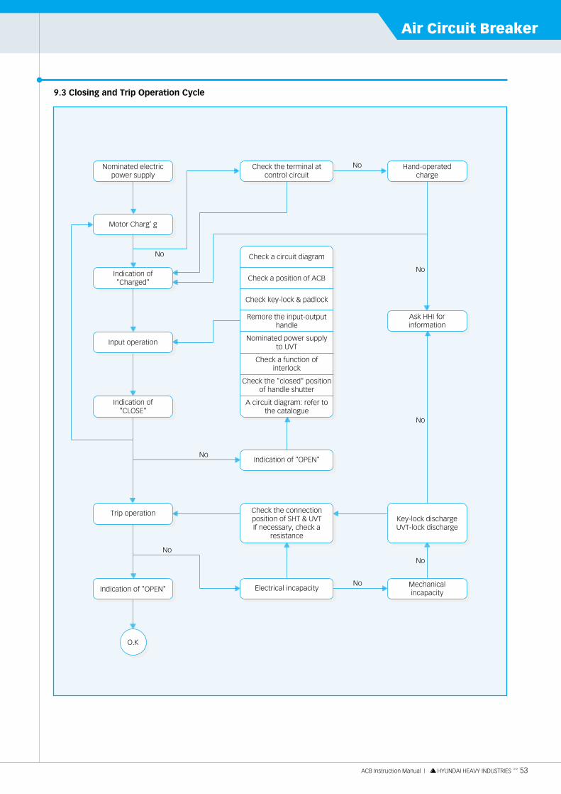
ACB Instruction Manual | HYUNDAI HEAVY INDUSTRIES >> 53
Air Circuit Breaker
9.3 Closing and Trip Operation Cycle
Nominated electricpower supply
Check the terminal atcontrol circuit
Hand-operatedcharge
Motor Charg’g
No
No
No
No
No
No
No
NoIndication of"Charged"
Indication of"CLOSE"
Input operation
Trip operation
Indication of "OPEN"
Indication of "OPEN"
Check the connectionposition of SHT & UVT If necessary, check a
resistance
Electrical incapacity
Ask HHI forinformation
Key-lock dischargeUVT-lock discharge
Mechanicalincapacity
@6X?@@)K@@@@@@6Khf@@@@@@@@6Khe@@@@@@@@@@6Kh@@@@@@@@@@@@6Xg@@@@@@@@@@@@@)K?f@@@@@@@@@@@@@@@@f@@@@@@@@@@@@@(M?f@@@@@@@@@@@@0Yg@@@@@@@@@@0Mh@@@@@@@@0Mhe@@@@@@0Mhf@@@@0Mhg@0M?
@6X?@@)K@@@@@@6Khf@@@@@@@@6Khe@@@@@@@@@@6Kh@@@@@@@@@@@@6Xg@@@@@@@@@@@@@)K?f@@@@@@@@@@@@@@@@f@@@@@@@@@@@@@(M?f@@@@@@@@@@@@0Yg@@@@@@@@@@0Mh@@@@@@@@0Mhe@@@@@@0Mhf@@@@0Mhg@0M?
@6X?@@)K@@@@@@6Khf@@@@@@@@6Khe@@@@@@@@@@6Kh@@@@@@@@@@@@6Xg@@@@@@@@@@@@@)K?f@@@@@@@@@@@@@@@@f@@@@@@@@@@@@@(M?f@@@@@@@@@@@@0Yg@@@@@@@@@@0Mh@@@@@@@@0Mhe@@@@@@0Mhf@@@@0Mhg@0M?
@6X?@@)K@@@@@@6Khf@@@@@@@@6Khe@@@@@@@@@@6Kh@@@@@@@@@@@@6Xg@@@@@@@@@@@@@)K?f@@@@@@@@@@@@@@@@f@@@@@@@@@@@@@(M?f@@@@@@@@@@@@0Yg@@@@@@@@@@0Mh@@@@@@@@0Mhe@@@@@@0Mhf@@@@0Mhg@0M?
@6X?@@)K@@@@@@6Khf@@@@@@@@6Khe@@@@@@@@@@6Kh@@@@@@@@@@@@6Xg@@@@@@@@@@@@@)K?f@@@@@@@@@@@@@@@@f@@@@@@@@@@@@@(M?f@@@@@@@@@@@@0Yg@@@@@@@@@@0Mh@@@@@@@@0Mhe@@@@@@0Mhf@@@@0Mhg@0M?
@6X?@@)K@@@@@@6Khf@@@@@@@@6Khe@@@@@@@@@@6Kh@@@@@@@@@@@@6Xg@@@@@@@@@@@@@)K?f@@@@@@@@@@@@@@@@f@@@@@@@@@@@@@(M?f@@@@@@@@@@@@0Yg@@@@@@@@@@0Mh@@@@@@@@0Mhe@@@@@@0Mhf@@@@0Mhg@0M?
@6X?@@)K@@@@@@6Khf@@@@@@@@6Khe@@@@@@@@@@6Kh@@@@@@@@@@@@6Xg@@@@@@@@@@@@@)K?f@@@@@@@@@@@@@@@@f@@@@@@@@@@@@@(M?f@@@@@@@@@@@@0Yg@@@@@@@@@@0Mh@@@@@@@@0Mhe@@@@@@0Mhf@@@@0Mhg@0M?
@6X?@@)K@@@@@@6Khf@@@@@@@@6Khe@@@@@@@@@@6Kh@@@@@@@@@@@@6Xg@@@@@@@@@@@@@)K?f@@@@@@@@@@@@@@@@f@@@@@@@@@@@@@(M?f@@@@@@@@@@@@0Yg@@@@@@@@@@0Mh@@@@@@@@0Mhe@@@@@@0Mhf@@@@0Mhg@0M?
@6X?@@)K@@@@@@6Khf@@@@@@@@6Khe@@@@@@@@@@6Kh@@@@@@@@@@@@6Xg@@@@@@@@@@@@@)K?f@@@@@@@@@@@@@@@@f@@@@@@@@@@@@@(M?f@@@@@@@@@@@@0Yg@@@@@@@@@@0Mh@@@@@@@@0Mhe@@@@@@0Mhf@@@@0Mhg@0M?
@6X?@@)K@@@@@@6Khf@@@@@@@@6Khe@@@@@@@@@@6Kh@@@@@@@@@@@@6Xg@@@@@@@@@@@@@)K?f@@@@@@@@@@@@@@@@f@@@@@@@@@@@@@(M?f@@@@@@@@@@@@0Yg@@@@@@@@@@0Mh@@@@@@@@0Mhe@@@@@@0Mhf@@@@0Mhg@0M?
@6X?
@@)K
@@@@@@6Kh
f
@@@@@@@@6Kh
e
@@@@@@@@@@6Kh
@@@@@@@@@@@@6Xg
@@@@@@@@@@@@@)K?f
@@@@@@@@@@@@@@@@f
@@@@@@@@@@@@@(M?f
@@@@@@@@@@@@0Yg
@@@@@@@@@@0Mh
@@@@@@@@0Mh
e
@@@@@@0Mh
f
@@@@0Mh
g
@0M?
@6X?
@@)K
@@@@@@6Kh
f
@@@@@@@@6Kh
e
@@@@@@@@@@6Kh
@@@@@@@@@@@@6Xg
@@@@@@@@@@@@@)K?f
@@@@@@@@@@@@@@@@f
@@@@@@@@@@@@@(M?f
@@@@@@@@@@@@0Yg
@@@@@@@@@@0Mh
@@@@@@@@0Mh
e
@@@@@@0Mh
f
@@@@0Mh
g
@0M?
@6X?
@@)K
@@@@@@6Kh
f
@@@@@@@@6Kh
e
@@@@@@@@@@6Kh
@@@@@@@@@@@@6Xg
@@@@@@@@@@@@@)K?f
@@@@@@@@@@@@@@@@f
@@@@@@@@@@@@@(M?f
@@@@@@@@@@@@0Yg
@@@@@@@@@@0Mh
@@@@@@@@0Mh
e
@@@@@@0Mh
f
@@@@0Mh
g
@0M?
@6X?
@@)K
@@@@@@6Kh
f
@@@@@@@@6Kh
e
@@@@@@@@@@6Kh
@@@@@@@@@@@@6Xg
@@@@@@@@@@@@@)K?f
@@@@@@@@@@@@@@@@f
@@@@@@@@@@@@@(M?f
@@@@@@@@@@@@0Yg
@@@@@@@@@@0Mh
@@@@@@@@0Mh
e
@@@@@@0Mh
f
@@@@0Mh
g
@0M?
@6X?
@@)K
@@@@@@6Kh
f
@@@@@@@@6Kh
e
@@@@@@@@@@6Kh
@@@@@@@@@@@@6Xg
@@@@@@@@@@@@@)K?f
@@@@@@@@@@@@@@@@f
@@@@@@@@@@@@@(M?f
@@@@@@@@@@@@0Yg
@@@@@@@@@@0Mh
@@@@@@@@0Mh
e
@@@@@@0Mh
f
@@@@0Mh
g
@0M?
@6X?
@@)K
@@@@@@6Kh
f
@@@@@@@@6Kh
e
@@@@@@@@@@6Kh
@@@@@@@@@@@@6Xg
@@@@@@@@@@@@@)K?f
@@@@@@@@@@@@@@@@f
@@@@@@@@@@@@@(M?f
@@@@@@@@@@@@0Yg
@@@@@@@@@@0Mh
@@@@@@@@0Mh
e
@@@@@@0Mh
f
@@@@0Mh
g
@0M?
@6X?
@@)K
@@@@@@6Kh
f
@@@@@@@@6Kh
e
@@@@@@@@@@6Kh
@@@@@@@@@@@@6Xg
@@@@@@@@@@@@@)K?f
@@@@@@@@@@@@@@@@f
@@@@@@@@@@@@@(M?f
@@@@@@@@@@@@0Yg
@@@@@@@@@@0Mh
@@@@@@@@0Mh
e
@@@@@@0Mh
f
@@@@0Mh
g
@0M?
@6X?
@@)K
@@@@@@6Kh
f
@@@@@@@@6Kh
e
@@@@@@@@@@6Kh
@@@@@@@@@@@@6Xg
@@@@@@@@@@@@@)K?f
@@@@@@@@@@@@@@@@f
@@@@@@@@@@@@@(M?f
@@@@@@@@@@@@0Yg
@@@@@@@@@@0Mh
@@@@@@@@0Mh
e
@@@@@@0Mh
f
@@@@0Mh
g
@0M?
@6X?
@@)K
@@@@@@6Kh
f
@@@@@@@@6Kh
e
@@@@@@@@@@6Kh
@@@@@@@@@@@@6Xg
@@@@@@@@@@@@@)K?f
@@@@@@@@@@@@@@@@f
@@@@@@@@@@@@@(M?f
@@@@@@@@@@@@0Yg
@@@@@@@@@@0Mh
@@@@@@@@0Mh
e
@@@@@@0Mh
f
@@@@0Mh
g
@0M?
@6X?
@@)K
@@@@@@6Kh
f
@@@@@@@@6Kh
e
@@@@@@@@@@6Kh
@@@@@@@@@@@@6Xg
@@@@@@@@@@@@@)K?f
@@@@@@@@@@@@@@@@f
@@@@@@@@@@@@@(M?f
@@@@@@@@@@@@0Yg
@@@@@@@@@@0Mh
@@@@@@@@0Mh
e
@@@@@@0Mh
f
@@@@0Mh
g
@0M?
@6X?
@@)K
@@@@@@6Kh
f
@@@@@@@@6Kh
e
@@@@@@@@@@6Kh
@@@@@@@@@@@@6Xg
@@@@@@@@@@@@@)K?f
@@@@@@@@@@@@@@@@f
@@@@@@@@@@@@@(M?f
@@@@@@@@@@@@0Yg
@@@@@@@@@@0Mh
@@@@@@@@0Mh
e
@@@@@@0Mh
f
@@@@0Mh
g
@0M?
@6X?
@@)K
@@@@@@6Kh
f
@@@@@@@@6Kh
e
@@@@@@@@@@6Kh
@@@@@@@@@@@@6Xg
@@@@@@@@@@@@@)K?f
@@@@@@@@@@@@@@@@f
@@@@@@@@@@@@@(M?f
@@@@@@@@@@@@0Yg
@@@@@@@@@@0Mh
@@@@@@@@0Mh
e
@@@@@@0Mh
f
@@@@0Mh
g
@0M?
@6X?@@)K@@@@@@6Khf@@@@@@@@6Khe@@@@@@@@@@6Kh@@@@@@@@@@@@6Xg@@@@@@@@@@@@@)K?f@@@@@@@@@@@@@@@@f@@@@@@@@@@@@@(M?f@@@@@@@@@@@@0Yg@@@@@@@@@@0Mh@@@@@@@@0Mhe@@@@@@0Mhf@@@@0Mhg@0M?
O.K
Check a circuit diagram
Check a position of ACB
Check key-lock & padlock
Remore the input-outputhandle
Nominated power supply to UVT
Check a function ofinterlock
Check the "closed" positionof handle shutter
A circuit diagram: refer tothe catalogue

Appendix09
54 << ACB Instruction Manual | HYUNDAI HEAVY INDUSTRIES
DC24V S P - S N
ACB Protection Relay
PB(Open)
PB(Close)
SpringChargeOff Switch
Anti-pumpingCircuit
Control Circuit Lay-out APR-1S-AS type APR
ACB◆ Draw-out type
◆ Fixed type
9.4 HiAN & HiAH Draw-out Type Circuit Diagram / APR-1L-GS
*1: Attach at rated voltage DC125V *2: Option (MCR)

ACB Instruction Manual | HYUNDAI HEAVY INDUSTRIES >> 55
Air Circuit Breaker
(Sho
rt 'b
' con
tact
) opt
ion
PB
(Ope
n)A
ux. S
witc
h
Aux
. Sw
itch
PB
(Ope
n)
Main circuit
CT: Current Transformer for APR
Motor Charging/Closing Circuits
APR Protection Relay / APR-1L-GS(over-current protection)
Control Power Terminal (CP/I)
Indication Terminal
Indication Terminal
Indication Terminal
Magnetic Hold Trigger
For other type APR, please refer to page 58, 59.
- In case that you use shunt trip in combination withunder voltage trip, 1a contact (33, 34) shall be usedin the circuit of under voltage trip.
- Extensional auxiliary contact 1a1b is not applicableto HiAN40-63 and HiAH32.
19 20242628
222527
APAL AS AIAG
Under Voltage Trip (UVT)
Control Power Terminal
Remote Trip Terminal
Under Voltage Trip Coil
11 12T2T1
Shunt Trip (SHT)
Shunt Trip Coil
Charging Power Terminal
Closing Power Terminal
Charging Motor
Latch Release Coil
Resistances
1 243
Control Power Terminal87
Auxiliary Switch
Auxiliary Contact Terminal
Extensional Auxiliary Contact (1a1b)
4650
3147
Condenser Trip (CTD)
Control Power Terminal
Remote Trip Terminal
Condensor Trip Device
NP
CTD
VU
Spring Charge Switch
Spring Charge Switch Terminal1615
R1
UVT
MHT
M
LRC
SHT
Manufacturer wiring part User wiring part Disconnecting device
Position Switch
TEST position61-62 ON61-63 OFF64-65 ON64-66 OFF
CONNECTED position71-72 ON71-73 OFF74-75 ON74-76 OFF
INSERTED position84-85 ON84-86 OFF
ISOLATED position81-82 ON81-83 OFF
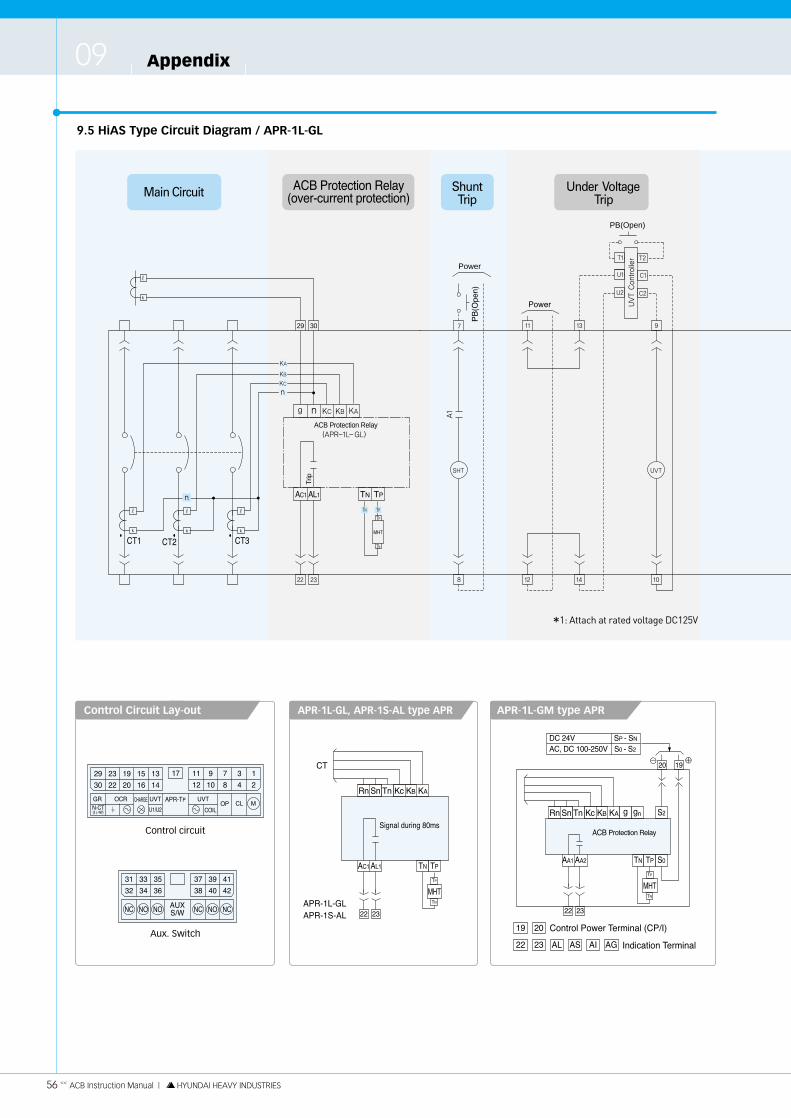
Appendix09
56 << ACB Instruction Manual | HYUNDAI HEAVY INDUSTRIES
29 30
ACB Protection Relay
Power
PB(Open)
9.5 HiAS Type Circuit Diagram / APR-1L-GL
Control Circuit Lay-out APR-1L-GL, APR-1S-AL type APR APR-1L-GM type APR
Control circuit
Aux. Switch
*1: Attach at rated voltage DC125V

ACB Instruction Manual | HYUNDAI HEAVY INDUSTRIES >> 57
Air Circuit Breaker
Power
Main circuit
CT: Current Transformer for APR
Motor Charging/Closing
APR Protection Relay / APR-1L-GL(over-current protection)
Control Power Terminal (CP/I)
Indication Terminal
Indication Terminal
Magnetic Hold Trigger
19 202527
2226
AL AS AIAL AS AI
Under Voltage Trip (UVT)
Control Power Terminal
Remote Trip Terminal
Under Voltage Trip Coil
9 10T2T1
Shunt Trip (SHT)
Shunt Trip Coil
Charging Power Terminal
Closing Power Terminal
Charging Motor
Latch Release Coil
Resistance
1 243
Control Power Terminal87
Auxiliary Switch
Auxiliary Contact Terminal4231
Capacitor Trip (CTD)
Control Power Terminal
Remote Trip Terminal
Condensor Trip Device
NPCTD
VU
Spring Charge Switch
Spring Charge Switch Terminal1615
R1
UVT
MHT
M
LRC
SHT
Manufacturer wiring part User wiring part Disconnecting device
For other type APR, please refer to page 56.
Position Switch
TEST position61-62 ON61-63 OFF64-65 ON64-66 OFF
CONNECTED position71-72 ON71-73 OFF74-75 ON74-76 OFF

Appendix09
58 << ACB Instruction Manual | HYUNDAI HEAVY INDUSTRIES
9.6 APR Wiring Diagrams
Rn Sn Tn KC KB KARn Sn Tn KC KB KA
Rn Sn Tn KC KB KARn Sn Tn KC KB KA
Rn Sn Tn KC KB KA Rn Sn Tn KC KB KA
3 pole 4 pole
APR-1L-GL
APR-1L-GSAPR-2L-GS
APR-1L-GM
Type

ACB Instruction Manual | HYUNDAI HEAVY INDUSTRIES >> 59
Air Circuit Breaker
Rn Sn Tn KC KB KA
Rn Sn Tn KC KB KA
Rn Sn Tn KC KB KARn Sn Tn KC KB KA
Rn Sn Tn KC KB KA
Rn Sn Tn KC KB KA
3 pole 4 pole
APR-1D-GM
APR-1S-AL
APR-1S-ASAPR-2S-AS
Type

9.7 Motor Unit Assembly Manual
1) Open the ACB front cover.
2) Check the associated parts (motor, motor control unit, screws).
3) Attach the motor control unit to motor control unit using R/H screw.
① Motor control unit … 1EA
② R/H screw (M3×10, with S/W) … 2EA
③ Motor unit … 1EA (110 V or 220 V).
4) Joint a D/H screws with motor control unit (after paste the loc-tite).
① Motor control unit … 1EA
② D/H screw (M3×10) … 2EA
5) After greasing motor shaft assemble motor ratchet/M and motor ratchet spring.
① Motor unit
② Motor ratchet/M … 1EA
③ Motor ratchet spring … 1EA
④ Hex wrench bolt (M6×12) … 2EA
⑤ S/washer (M6) … 2EA
Appendix09
60 << ACB Instruction Manual | HYUNDAI HEAVY INDUSTRIES
Motor cable terminal (wiring N0=1, 2)③ ① ②
②
①
②
③
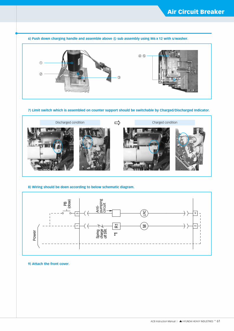
ACB Instruction Manual | HYUNDAI HEAVY INDUSTRIES >> 61
Air Circuit Breaker
6) Push down charging handle and assemble above ⑤ sub assembly using M6 x 12 with s/washer.
7) Limit switch which is assembled on counter support should be switchable by Charged/Discharged Indicator.
8) Wiring should be doen according to below schematic diagram.
9) Attach the front cover.
①
②③
④ ⑤
Charged conditionDischarged condition �

Appendix09
62 << ACB Instruction Manual | HYUNDAI HEAVY INDUSTRIES
9.8 Shunt Unit Assembly Manual
1) Open the ACB front cover.
2) Check the associated parts (shunt, shunt support, screws).
① Shunt unit … 1EA
② R/H screw (M4×10, with S/W) … 2EA
3) Attach the shunt unit to mechanism unit using R/H screw.
4) Wiring should be doen according to below schematic diagram.
5) Attach the front cover.
6) Shunt trip unit spec.
Assembled condition
Mech. unit (right side)
Shunt support
②
②
No NoRating voltage Rating voltageCoil resistance(Ω) Coil resistance(Ω)Resistance tolerance Resistance tolerance
1
2
3
4
5
6
7
8
AC 110 V
AC 110 V
AC 380 V
AC 440 V
DC 24 V
DC 48 V
DC 110 V
DC 220 V
25 Ω
101 Ω
352 Ω
472 Ω
2.7 Ω
9.7 Ω
36 Ω
161 Ω
±10 % ±10 %
①

ACB Instruction Manual | HYUNDAI HEAVY INDUSTRIES >> 63
Air Circuit Breaker
Date Contents Expenses A place of repair Name of engineer Signature
Repair and Inspection Contents
※ Please be sure to obtain the appropriate signatures after service. Please keep this table for management, maintenance, and after-sales service.

HH
IS-WZ-LE-013-05, ’10. 01 D
esigned by ADPAR
K
Head Office 1 Jeonha-dong, Dong-gu, Ulsan, Korea TEL. 82-52-202-8101~8 FAX. 82-52-202-8100
Seoul 140-2, Gye-dong, Jongno-gu, Seoul, Korea(Sales & Marketing) TEL. 82-2-746-7510, 8519 FAX. 82-2-746-7647
Orlando 3452 Lake Lynda Drive, Suite 170, Orlando, Florida 32817, U.S.A. Tel. 1-407-249-7350 Fax. 1-407-275-4940
New Jersey 300 Sylvan Avenue, Englewood Cliffs, NJ, 07632, U.S.A. Tel. 1-201-816-0286 Fax. 1-201-816-4083
London 2nd Floor, The Triangle, 5-17 Hammersmith Grove, London, W6 0LG, UKTel. 44-20-8741-0501 Fax. 44-20-8741-5620
Tokyo 8th Fl., Yurakucho Denki Bldg. 1-7-1, Yuraku-cho, Chiyoda-gu, Tokyo, 100-0006, Japan Tel. 81-3-3212-2076, 3215-7159 Fax. 81-3-3211-2093
Osaka l-Room 5th Fl., Nagahori-Plaza Bldg., 2-4-8, Minami Senba, Chuo-ku, Osaka, 542-0081, Japan Tel. 81-6-6261-5766, 5767 Fax. 81-6-6261-5818
Dubai Level 2, Unit 205 Emaar Square Bldg. 4, Sheikh Zayed Road, P.O. Box 252458, Dubai, U.A.E.Tel. 971-4-425-7995 Fax. 971-4-425-7996
Sofia 1271, Sofia 41, Rojen Blvd., BulgariaTel. 359-2-803-3200, 3220 Fax. 359-2-803-3203
Yangzhong No. 9 Xiandai Road, Xinba Scientific and Technologic Zone, Yangzhong, Jiangsu, P.R.C. Zip: 212212, ChinaTel. 86-511-8842-0666, 0212 Fax. 86-511-8842-0668, 0231
www.hyundai-elec.com