Embed Size (px)
Citation preview

CSH-8LMK2 sonar tips Basic system configuration
Minimum tube lengths


Fairings, leading and trailing examples Leading edge
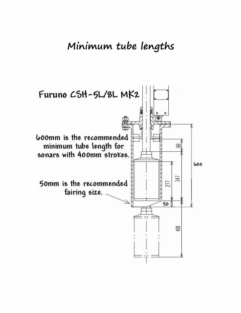
Trailing edge

Shaft collars Shaft collars are not required but are recommended. The addition of
a collar can help prevent kelp, lines and ropes from getting wrapped around the sonar shaft and pulled up inside the tube when the sound dome is being retracted.

Vikings latest shaft collar design.
Photo showing a 400mm stroke with no shaft collar installed.
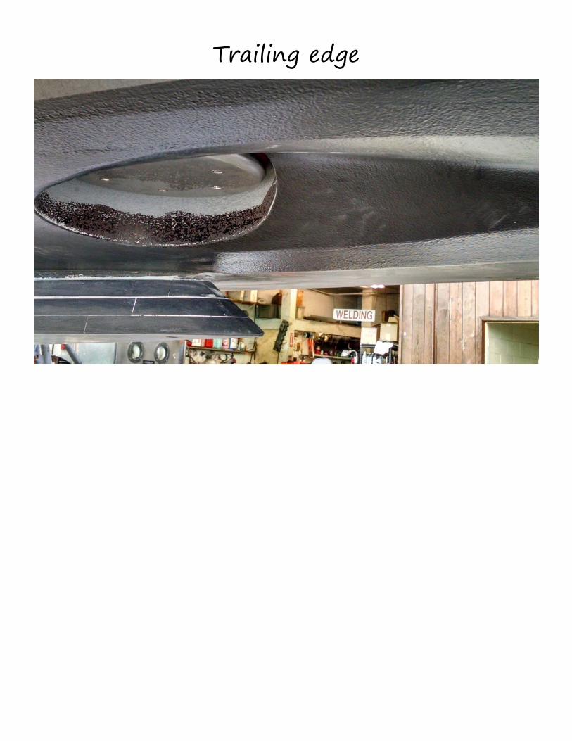
Hoist Unit Checks One item to be cautious of is the length and how the transducer cable
is routed exiting the top of the sonar shaft. If the cable to too long it can rub or get pinched when the hoist is lowered/raised. Below are a couple of examples of the cable being to long.

Recommend length
Transceiver mounting The sound dome comes with 6.6m of cable. After you add the shaft
and route the transducer cable through the attachment point you may only have 5m of cable to work with. It is highly recommended that the T/R unit be mounted vertical and in a cool well ventilated area if at all possible. If needed, a 6.6m transducer extension cable CSH-1700 is available.
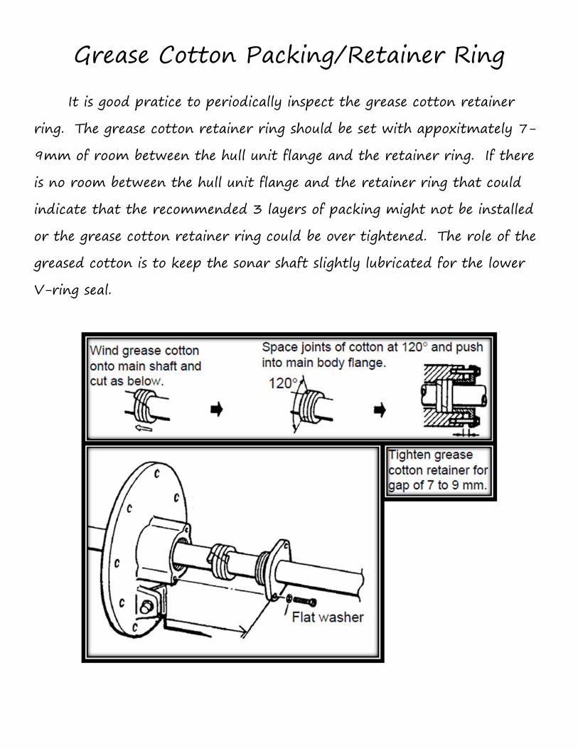
Grease Cotton Packing/Retainer Ring It is good pratice to periodically inspect the grease cotton retainer
ring. The grease cotton retainer ring should be set with appoxitmately 7-9mm of room between the hull unit flange and the retainer ring. If there is no room between the hull unit flange and the retainer ring that could indicate that the recommended 3 layers of packing might not be installed or the grease cotton retainer ring could be over tightened. The role of the greased cotton is to keep the sonar shaft slightly lubricated for the lower V-ring seal.

Raise/Lower Drive System
When the the grease cotton retainer ring is over tightened it can cause excess strain on sonar raise/lower drive motor. A simple check of the raise/lower time on the hoist unit can verify the drive system is operating within specification.
400mm Stroke 600mm Stroke 14 seconds 20 seconds
If the raise/lower time is longer than the recommended values above, a closer inspection of the grease cotton packing and retainer ring will be your next step. The grease cotton packing should not be frayed or show excess wear. If the packing has signs of wear/fatigue it can be replaced. Furuno Part Number: 000-177-698-10.
Correct setting Incorrect Setting

Auto Retraction Setup The auto retraction setup should be done at the commisioning stages.
The sonar can use GPS data to trigger this important safety feature. We all know in the heat of battle certain things can be pushed aside and forgotton about. When this feature is setup the the sonar hoist unit will auto retract when the speed threshold is reached.
Verify with the installer a GPS has been interfaced with the sonar processor. You should see an indication on the main display located at the top right of the screen.
To setup, press the [MENU] key, use the [RANGE] control to choose the [MENU MODE], use the [GAIN] control to select SYSTEM.
Use the [Range] control to select AUTO RETRACT.
Use the [Range] control to move the cursor to the AUTO RETRACT setting.
Use the [Gain] control to set the speed threshold for the AUTO RETRACT feature. Recommended retraction speed is 10 or 11 knots.

Needed tools.