Embed Size (px)
Citation preview
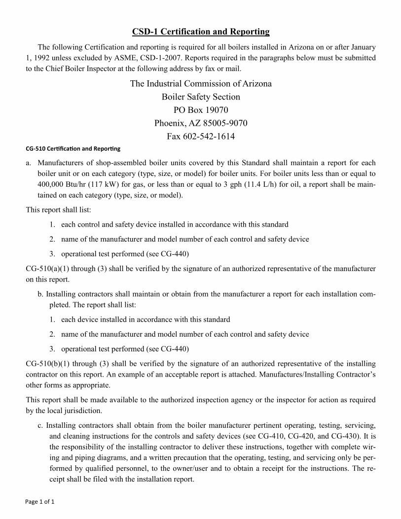
CSD-1 Certification and Reporting
The following Certification and reporting is required for all boilers installed in Arizona on or after January
1, 1992 unless excluded by ASME, CSD-1-2007. Reports required in the paragraphs below must be submitted
to the Chief Boiler Inspector at the following address by fax or mail.
The Industrial Commission of Arizona
Boiler Safety Section
PO Box 19070
Phoenix, AZ 85005-9070
Fax 602-542-1614
CG-510 Certification and Reporting
a. Manufacturers of shop-assembled boiler units covered by this Standard shall maintain a report for each
boiler unit or on each category (type, size, or model) for boiler units. For boiler units less than or equal to
400,000 Btu/hr (117 kW) for gas, or less than or equal to 3 gph (11.4 L/h) for oil, a report shall be main-
tained on each category (type, size, or model).
This report shall list:
1. each control and safety device installed in accordance with this standard
2. name of the manufacturer and model number of each control and safety device
3. operational test performed (see CG-440)
CG-510(a)(1) through (3) shall be verified by the signature of an authorized representative of the manufacturer
on this report.
b. Installing contractors shall maintain or obtain from the manufacturer a report for each installation com-
pleted. The report shall list:
1. each device installed in accordance with this standard
2. name of the manufacturer and model number of each control and safety device
3. operational test performed (see CG-440)
CG-510(b)(1) through (3) shall be verified by the signature of an authorized representative of the installing
contractor on this report. An example of an acceptable report is attached. Manufactures/Installing Contractor’s
other forms as appropriate.
This report shall be made available to the authorized inspection agency or the inspector for action as required
by the local jurisdiction.
c. Installing contractors shall obtain from the boiler manufacturer pertinent operating, testing, servicing,
and cleaning instructions for the controls and safety devices (see CG-410, CG-420, and CG-430). It is
the responsibility of the installing contractor to deliver these instructions, together with complete wir-
ing and piping diagrams, and a written precaution that the operating, testing, and servicing only be per-
formed by qualified personnel, to the owner/user and to obtain a receipt for the instructions. The re-
ceipt shall be filed with the installation report.
Page 1 of 1

Block Information to be filled in
1. Manufacturer’s name (located on ASME plate or manufacturer’s data report)
2. Manufacturer’s address, street, City, State
3. Manufacturer’s Zip Code
4. Manufacturer’s Phone Number
5. Manufacturer’s Fax Number (if available)
6. Manufacturer’s Model Number (from the unit or manufacturer’s manual)
7. Year the unit was built (from ASME plate)
8. National Board Number (located at top of ASME name plate)
9. Serial Number of the unit (from ASME nameplate or manufacturer’s data report)
10. Underwriter’s Laboratory Number (if available)
11. Canadian Standards Association Number (if availa-ble)
(Items 12 and 13 are for Steam boilers only)
12. Maximum Allowable Working Pressure (from ASME plate)
13. Minimum Safety Valve relieving capacity required (from ASME plate)
(Items 14-16 for water boilers only N/A for steam boil-ers)
14. Maximum Allowable Working Pressure (from ASME plate)
15. Maximum Allowable Temperature (from ASME plate)
16. Minimum Safety Valve relieving capacity required (from ASME plate) (circle PPH or Btu as applicable)
17. Boiler Type (i.e. Cast Iron, Water Tube, Fire Tube etc.)
18. Square feet of heating surface (from ASME plate)
19. Total Btu/hr input capacity
20. Total Btu/hr output capacity
21. If modular boiler, number of modules
22. Burner manufacturer (if available)
23. Burner Model Number (if available)
24. Underwriter’s Laboratory No. or Canadian Stand-ards Association No. (if available)
25. Burner Serial Number (if available)
26. Type of fuels connected to the burner assembly to be used. (i.e. natural gas, oil, propane etc.)
27. Gas manifold pressure (for natural, propane etc.)
28. High gas pressure switch setting (if switch is in-stalled)
29. Low gas pressure switch setting (if switch is in-stalled)
30. Oil pressure at the nozzle (for oil burners only)
31. Low oil pressure switch setting (if applicable)
32. Kilowatt input (electric boilers only)
33. Elements or Electrodes (electric boilers only)
34. Number of elements or electrodes (electric boil-ers only)
35. Owner/Users name for where the boiler will be installed
36. Owner/Users street address for where the boiler will be installed
37. Owner/Users city for where the boiler will be installed
38. Owner/Users Zip Code for where the boiler will be installed
39. Owner/Users Telephone number for where the boiler will be installed
40. Owner/Users Fax number for where the boiler will be installed (if available)
41. email address for contact (if available)
42. Actual Manufacturer’s Name for each control/device listed that is installed on the boiler
43. Manufacturer’s model number for each control/device listed that is installed on the boiler
44. Date the operational test was performed to check the control/device listed at manufacturer’s facility (note: the paragraph number under the name of the control/device is the CSD-1 para-graph that list the requirements must meet and its function) All installations shall have an oper-ational test performed by both the manufacturer and installing contractor’s representative.
45. Date the operational test was performed to check the control/device listed at place of instal-lation
46. Safety or safety relief valve manufacturer (SV or SRV)
47. Operational test of SV or SRV (date performed)
48. Model of pressure relieving device or devices
49. SV or SRV inlet & outlet size (i.e. 2”x3”)
50. SV or SRV Capacity (circle PPH/Btu as appro-priate)
51. Name of individual representing the equipment manufacturer
52. Signature of authorized representative of the manufacturer
53. Date signed authorized representative of the manufacturer
54. Name of the Installing Contractor
55. Signature of the Installing Contractor’s repre-sentative
56. Date signed by Installing Contractor’s repre-sentative
Instructions for filling out the ASME CSD-1 Manufacturer’s/Installing Contractors Report
Page 1 of 4

Page 2 of 4
1 2 3
4 5
7 6
8 9 10 11
12
13
14 15
16
17 18
20 21 19
25
26
23
24
22
29
30 31
27 28
34 33
36
35
32
37 38
39 40 41

Page 3 of 4
42 43 44 45

Page 4 of 4
46
48
49
47
50
52
51
53
54
55 56

State of Arizona
Boiler Safety Section
MANUFACTURER’S/INSTALLING CONTRACTORS REPORT FOR
ASME CSD-1
State of Arizona
Unit Manufacturer
Name ___________________________________________________ Address __________________________________________________ Zip ________________
Telephone__________________________________________________________ Fax _______________________________________________________________
Unit Identification (Boiler)
Manufacturer’s Model #_______________________________________________ Year Built __________________________________________________________
National Board # ___________________________ Serial # __________________________ UL #________________________CSA # __________________________
Jurisdiction ____________________________________________________________________________________________________________________________
Steam Hot Water
Maximum Working Pressure ________________________ psig Maximum Working Pressure ______________ psig Maximum Temperature _______________°F
Minimum Safety Valve Capacity ______________________PPH Minimum Safety Relief Valve Capacity ______________________________________ BTU or PPH
Boiler Unit Description (type) _______________________________________ Square Foot Heating Surface (cast iron & aluminum exempt) ______________
Boiler Unit Capacity (input/output) ________________________ /___________________________ If Modular (number of modules) _________________
Burner
Manufacturer ________________________________________ Model _________________________________________________________________________
UL or CSA # ________________________________________ Serial # _____________________________________________________________________________
Fuels (as shipped) __________________________________________________________________________________________________________________
Indicate Units (where not applicable, indicate “N/A”)
Gas Manifold Pressure ____________________ High Gas Pressure Switch Setting ___________________ Low Gas Pressure Switch Setting ____________________
Oil Nozzle/Delivery Pressure (at maximum input) _______________________ Low Oil Pressure Switch Setting ____________________________________________
Kilowatt Input ____________________________ Type (elements or electrode) _________________ Number of Elements or Electrodes _______________________
Installation Location (if known)
Customer Name ________________________________________________________________________________________________________________________
Address ______________________________________________________________________________________________________________________________
City _____________________________________________ State _____________Arizona_____________________________ Zip ____________________________
Telephone _______________________________ Fax __________________________ Email __________________________________________________________
Page 1 of 3

Certification and Reporting (CG-500) for Controls and Safety Devices (Cont’d)
Operational Test Performed, Date
Control Device Manufacturer Model # Manufacturer / Installing Contractor
Operating Controls
Low Water Fuel Cutoff
CW-120(a), CW-140 ______________________________ ___________________________ _________________/________________
Forced Circulation
CW-210(a) ______________________________ ___________________________ _________________/________________
Steam Pressure
CW-310(b) ______________________________ ___________________________ _________________/________________
Water Temperature
CW-410(b) ______________________________ ___________________________ _________________/________________
Safety Controls
Low Water Fuel Cutoff
CW-120(a), CW-120(b)
CW-130, CW-140 ______________________________ ____________________________ _________________/________________
Forced Circulation
CW-210(b) ______________________________ ____________________________ _________________/________________
High Steam Pressure Limit
CW-310(c) ______________________________ ____________________________ _________________/________________
High Water Temperature Limit
CW-410(c) ______________________________ ____________________________ _________________/________________
Fuel Safety Shutoff Valve, Main
CF-180(b)(2), CF-180(b)(3) ______________________________ ____________________________ _________________/________________
Pilot Safety Shutoff Valve
CF-180(c) ______________________________ ____________________________ _________________/________________
Atomizing Medium Switch
CF-450(b) ______________________________ ____________________________ _________________/________________
Combustion Air Switch
CF-220 ______________________________ ____________________________ _________________/________________
High Gas Pressure Switch
CF-162 ______________________________ ____________________________ _________________/________________
Low Gas Pressure Switch
CF-162 ______________________________ ____________________________ _________________/________________
Low Oil Pressure Switch
CF-450(a) ______________________________ ____________________________ _________________/________________
High Oil Temperature Switch
CF-450(c) ______________________________ ____________________________ _________________/________________
Low Oil Temperature Switch
CF-450(d) ______________________________ ____________________________ _________________/________________
Purge Air Flow
CF-210 ______________________________ ____________________________ _________________/________________
Flame Safeguard (Primary)
CF-310, CF-320 ______________________________ ____________________________ _________________/________________
Flame Detector
CF-310, CF-320 ______________________________ ____________________________ _________________/________________
Low Fire Start
Low-Fire Start Switch
CF-610 ______________________________ ____________________________ _________________/________________
Page 2 of 3

Certification and Reporting (CG-500) for Controls and Safety Devices (Cont’d)
Safety or Safety Relief Valve, CW-510, CW-520 (if more than one valve, list all SV or SRV below)
Manufacturer ____________________________________________________ Operational Test Performed, Date ____________/____________/____________
Model (s) _____________________________________________________________________________________________________________________________
Size (s) _______________________________________________________________________________________________________________________________
Capacity (s) __________________________________________________________________________________________________________________PPH/Btu/hr
——————————————————————————————————————————————————————————-———————————————-
Representing Equipment Manufacturer, Name _______________________________________________________________________________________________
Signature ________________________________________________________________ Date_________________________________________________________
—————————————————————————————————————————————————————————————————————————--
Representing Installing Contractor, Name ___________________________________________________________________________________________________
Signature ________________________________________________________________ Date ________________________________________________________
Page 3 of 3


![Facebook Certification - Reporting & analytics [curriculum]](https://img.dokumen.tips/doc/110x75/55c2a1a3bb61eb9b358b47a4/facebook-certification-reporting-analytics-curriculum.jpg)