Embed Size (px)
DESCRIPTION
Crystal DesignStructure and Function Perspectives in Supramolecular Chemistry Volume 7 - GAUTAM R
Citation preview

Crystal Design:Structure and Function
Crystal Design: Structure and Function. Volume 7Edited by Gautam R. Desiraju
Copyright 2003 John Wiley & Sons, Ltd.ISBN: 0-470-84333-0
Editorial Board
Founding Editor
J.-M. Lehn, ColleÁge de France, Chimie des Interactions MoleÂculaires, 11 Place
Marcelin Berthelot, 75005 Paris, France
Editors
C.J. Burrows, Of®ce 3152 HEB, Department of Chemistry, University of Utah,
315 S. 1400 East, RM Dock, Salt Lake City, UT 84112, Utah, USA
G.R. Desiraju, University of Hyderabad, School of Chemistry, Hyderabad
500046, India
A.D. Hamilton, Yale University, Department of Chemistry, New Haven, CT
06520, USA
D. Hilvert, Laboratorium fuÈr Organische Chemie, ETH Zentrum, UniversitaÈts-
strasse 16, 8092 ZuÈrich, Switzerland
D.N. Reinhoudt, University of Twente, Faculty of Chemical Technology, P.O.
Box 217, NL-7500 AE Enschede, The Netherlands
J.-P Sauvage, Universite Louis Pasteur, Institut le Bel, 4 Rue Blaise Pascal,
F-67070 Strasbourg, France
Former Editors
J.-P. Behr, Faculte de Pharmacie. Universite Louis Pasteur, Strasbourg, B.P. 24,
F-67401 Illkirch, France
T. Kunitake, Kyushu University, Faculty of Engineering. Hakozaki, Fukuoka
812, Japan
Crystal Design:Structure andFunctionPerspectives in
Supramolecular Chemistry
Volume 7
EDITED BY GAUTAM R. DESIRAJU
University of Hyderabad, Hyderabad, India
Copyright # 2003 John Wiley & Sons Ltd,
The Atrium, Southern Gate, Chichester,
West Sussex PO19 8SQ, England
Telephone (�44) 1243 779777
E-mail (for orders and customer service enquiries): [email protected]
Visit our Home Page on www.wileyeurope.com
or www.wiley.com
All Rights Reserved. No part of this publication may be reproduced, stored in a retrieval system or
transmitted in any form or by any means, electronic, mechanical, photocopying, recording, scanning
or otherwise, except under the terms of the Copyright, Designs and Patents Act 1988 or under the
terms of a licence issued by the Copyright Licensing Agency Ltd, 90 Tottenham Court Road,
London W1T 4LP, UK, without the permission in writing of the Publisher. Requests to the
Publisher should be addressed to the Permissions Department, John Wiley & Sons Ltd, The
Atrium, Southern Gate, Chichester, West Sussex PO19 8SQ, England, or e-mailed to
[email protected], or faxed to (�44) 1243 770620.
This publication is designed to provide accurate and authoritative information in regard to the
subject matter covered. It is sold on the understanding that the Publisher is not engaged in
rendering professional services. If professional advice or other expert assistance is required, the
services of a competent professional should be sought.
Other Wiley Editorial Offices
John Wiley & Sons Inc., 111 River Street, Hoboken, NJ 07030, USA
Jossey-Bass, 989 Market Street, San Francisco, CA 94103±1741, USA
Wiley-VCH Verlag GmbH, Boschstr. 12, D-69469 Weinheim, Germany
John Wiley & Sons Australia Ltd, 33 Park Road, Milton, Queensland 4064, Australia
John Wiley & Sons (Asia) Pte Ltd, 2 Clementi Loop #02±01, Jin Xing Distripark, Singapore
129809
John Wiley & Sons Canada Ltd, 22 Worcester Road, Etobicoke, Ontario, Canada M9W 1L1
Library of Congress Cataloging-in-Publication Data
Crystal design: structure and function / edited by Gautam R. Desiraju.
p. cm. ± (Perspectives in supramolecular chemistry; v. 6)
Includes bibliographical references and indexes.
ISBN 0-470-84333-0 (alk. paper)
1. Molecular crystals. 2. Crystal growth. 3. Crystallography. I. Desiraju, G. R.
(Gautam R.) II. Series.
QD921 .C787 2003
5480.5±dc21 2002193382
British Library Cataloguing in Publication Data
A catalogue record for this book is available from the British Library
ISBN 0 470 84333 0
Typeset in 10/12pt Times by Kolam Information Services Pvt. Ltd, Pondicherry, India.
Printed and bound in Great Britain by TJ International, Padstow, Cornwall.
This book is printed on acid-free paper responsibly manufactured from sustainable forestry in
which at least two trees are planted for each one used for paper production.
Contents
Contributors vii
Preface ix
1 Hydrogen Bonds in Inorganic Chemistry:
Application to Crystal Design 1
Lee Brammer
2 Molecular Recognition and Self-Assembly
Between Amines and Alcohols (Supraminols) 77
Raffaele Saladino and Stephen Hanessian
3 Very Large Supramolecular Capsules Based on
Hydrogen Bonding 153
Jerry L. Atwood, Leonard J. Barbour and Agoston Jerga
4 Molecular Tectonics: Molecular Networks Based on
Inclusion Processes 177
Julien Martz, Ernest Graf, Andre De Cian and Mir Wais Hosseini
5 Layered Materials by Design: 2D Coordination
Polymeric Networks Containing Large Cavities/Channels 211
Kumar Biradha and Makoto Fujita

6 The Construction of One-, Two- and Three-Dimensional
Organic±Inorganic Hybrid Materials from Molecular
Building Blocks 241
Robert C. Finn, Eric Burkholder and Jon A. Zubieta
7 A Rational Approach for the Self-Assembly of
Molecular Building Blocks in the Field of
Molecule-Based Magnetism 275
Melanie Pilkington and Silvio Decurtins
8 Polymorphism, Crystal Transformations and Gas±Solid Reactions 325
Dario Braga and Fabrizia Grepioni
9 Solid±Gas Interactions Between Small Gaseous
Molecules and Transition Metals in the Solid State.
Toward Sensor Applications 375
Michel D. Meijer, Robertus J. M. Klein Gebbink
and Gerard van Koten
Cumulative Author Index 387
Cumulative Title Index 393
Index 397
vi Contents
�����������
���� � ������� ���������� ���� ����� �� ���� �� � ���� ������ ��
����� �� �� ������ ���
������ � �������� ���������� ���� ����� �� ���� �� � ���� ������ ��
����� �� �� ������ ���
����� �������� ��� ���� �!�� "�# ���� �#� $�#�� �� ���� ��� �� %���%��
$�#�� &�&�'�()� *����
����� ������ � ���� ���� �� � !� ++�, � �� ! ��--� . � /, ���� �� 01&(����
2�#��� 0����
�� �������� ���������� ���� ����� �� ���� �� ���3�� � ���3��
�)45/� �6
���� ����������� ���������� ���� ����� ����!��� �� ���� ��� ����!���� $7
�)�&&� ���
������ �� ����� 8����� �� � �� � � � �� ��� � ��#�� 9��� :�!�� 9��
���;!��� �� �� �� �� <�$=� /=" �&�)>� �� ���� ��; 8� � ?������� 0��� ��� 8�
2��� /1�4(4( ��������#� /���!�
��� �� ��������� ���������� ���� ���� �� 2 !��� ����� �� ���� �� 2�����
/�� �������� )� �51)(�� 2����� �@ �A�����
!����� �� "���� ���������� ���� ����� ����!��� �� ���� ��� ����!���� $7
�)�&&� ���
#����� "�$���� ��� ���� �!�� "�# ���� �#� $�#�� �� ���� ��� �� %���%��
$�#�� &�&�'�()� *����
����� %��&� 8����� �� � �� � � � �� ��� � ��#�� 9��� :�!�� 9��
���;!��� �� �� �� �� <�$=� /=" �&�)>� �� ���� ��; 8� � ?������� 0��� ��� 8�
2��� /1�4(4( ��������#� /���!�
"����'�� %��(����� � ���� ���� �� � !�� . � . ���� �� 01(4�((� ������ � 0����
���(��� )������� ���������� ���� ����� �� ���� ��; � �����;��� �,?, ���'�
��!!, ������1. ���� �����;��� B�� 5)� )*4� ���� �
#�� *�� )������ 8����� �� � �� � � � �� ��� � ��#�� 9��� :�!�� 1
9�� ���;!��� �� �� �� �� <�$=� /=" �&�)>� �� ���� ��; 8� � ?������� 0��� ���
8� 2��� /1�4(4( ��������#� /���!�
������ ����� ���������� ���� ����� �� ���� �� � ���� ������ ��
����� �� �� ������ ���
!������ � #� ����� %������� ���������� �����1�� ��� ������� �� �����
0��� ����� ����!�� �� ���� ��� ?� ������ '� )�'& �5 ����!��� :�� $�������� �
����� #���'� 8����� �� � �� � � � �� ��� � ��#�� 9��� :�!�� 9��
���;!��� �� �� �� �� <�$=� /=" �&�)>� �� ���� ��; 8� � ?������� 0��� ��� 8�
2��� /1�4(4( ��������#� /���!�
#����� �� #��$��� ���������� �����1�� ��� ������� �� ����� 0��� �����
����!�� �� ���� ��� ?� ������ '� )�'& �5 ����!��� :�� $�������� �
#������ +���������� ���������� ���� ���� �� 2 !��� ����� �� ���� ��
2����� /�� �������� )� �51)(�� 2����� �@ �A�����
!�&&���� ��������� � ���� ���� �#� � �# � � �#�!� � !�� �� ���� ��C �#�
��� ���� :��! �� . � �, ��� �� � 8 �� �� �,�,!,� (��(( . ����� 0����
%����� �� ������ ���������� �����1�� ��� ������� �� ����� 0��� �����
����!�� �� ���� ��� ?� ������ '� )�'& �5 ����!��� :�� $�������� �
�� �� ,������� ���������� ���� ����� ����!��� �� ���� ��� ����!���� $7
�)�&&� ���
� �����������
Preface
Supramolecular chemistry, or chemistry beyond the molecule, has provided a wide
canvas for a variety of studies of molecular materials in the solid state. The most
orderly manifestations of the solid state are single crystals, and the earlier volume
in this series with the present Editor, The Crystal as a Supramolecular Entity,
sought to establish that the crystal is the perfect example of a supramolecular
assembly, justifying as it were the earlier statements of Dunitz and Lehn in this
regard.
Six years down the line, the supramolecular paradigm has continued to supply
a reliable rubric for establishing the grammar of a new and rapidly growing
subject, crystal engineering. The present volume is about crystal engineering, or
design, and tries to establish connections between the structures of molecular
materials and their properties. Crystal engineering links the domains of intermo-
lecular interactions, crystal structures and crystal properties. Without interactions
there cannot be structures, and without worthwhile properties as a goal, there
cannot be suf®cient reason for designing structures. In the process, many
advances have been made in fabricating the nuts and bolts of crystal engineering.
This is what is summarised in the present volume. So, if the earlier volume was
conceptual in its theme, the present one has more to do with methodology and
practice.
A major conclusion that emerges from this work is the great utility of de®ning a
crystal structure as a network. This is true for all varieties of molecular crystals
ranging from simple organics to labyrinthine coordination polymers that incorp-
orate both inorganic and organic components. I hesitate to use the term `building
block' here, although several of the authors have done so, if only because in the
softest of molecular solids, namely the pure organics, the building blocks are
themselves pliable. This pliability is chemical rather than mechanical ± a given
organic molecule presents many faces to its neighbours and the slightest of modi-
®cations may mean that its recognition pro®le changes drastically. Accordingly,
the term `building block' is inappropriate for pure neutral organics, but it may be
employed with increasing degrees of con®dence as the intermolecular interactions
become stronger and more directional. This, then, is the winning advantage of
coordination polymers. The well de®ned coordination environment around the
metal atom and the strong, directional nature of its interactions with the organic
ligands that surround it mean that not only may a coordination polymer be
designed reliably but also that its topological depiction as a network is the most
natural one.
If coordination bonds to metal centres are robust design elements, the hydrogen
bond or hydrogen bridge does not lag far behind. This master key of molecular
recognition combines strength with suppleness and can be employed in a great
many chemical situations. These interactions have been treated in some detail in
this volume, in their organic, inorganic and ionic variations. Every stage in the
development of the chemical sciences has witnessed much progress with respect to
understanding hydrogen bonding and the supramolecular era is no exception. In
addition to its use as an exclusive design element, a hydrogen bond may be used
along with coordination bonds and even more precise structural control is
obtained. Such combinations of interactions are always more effective than single
interactions, however strong the latter may be. In the most favourable synergies,
supramolecular synthons are obtained that may used with the highest levels of
con®dence in crystal engineering.
What now of properties? Does crystal engineering lose its innate character when
the designed materials do not have any obvious property? Surely not ± for how
does one write a poem if one does not know how to arrange words together? The
grammar of crystal design is devilishly complex. Most crystal structures, even
those of coordination polymers, are not modular. The building blocks continue to
twist and turn and interaction interference is always a danger. This, then, is the
real goal of the subject ± to identify systems that are modular, wherein a family of
related molecules will yield a family of related crystal structures. Hierarchy is still
elusive in most cases because of the supramolecular nature of the systems
employed, and with the further complication that crystallisation is a kinetically
controlled process rather than a thermodynamic one, issues of modularity and
hierarchy will be the most dif®cult challenges for the crystal engineer for some
time to come. Despite these limitations, and they are formidable ones, consider-
able progress has been made with respect to property design. The present volume
describes materials that act as sensors, catalysts, microporous substances and
molecular magnets. Polymorphism is addressed in this volume, although it is still
deemed by most to be too intractable an issue with respect to design of either
form or function.
Crystal engineering, which has now grown comfortably out of its organic
origins to include inorganic compounds within its ambit, will no doubt further
extend its scope from single crystals to micro- and nanocrystalline materials and
to crystals of lower dimensionalities, and with this the transition from structure to
x Preface

properties will only become more complete. In the meantime, and as we anticipate
the fuller coming together of crystal engineering, supramolecular chemistry and
materials science, the perspectives provided in the present volume are ample
enough for analysis and assessment.
Gautam R. Desiraju
Hyderabad, June 2002
Preface xi

Plate 1 (Figure 1.3).M(left). Domainmodel for hydrogen bonding involvingmetal complexes. Metal Domain (blue);Ligand Domain (green); PeripheryDomain (red); Environment (cyan).
Plate 2 (Figure 1.4).M(right). Diamondoid (M)O–H…N hydrogen-bonded network in crystalline[Mn(�3-OH)(CO)3]4·2(4,4’-bipy)·2CH3CN. O–Hgroups (red); 4,4’-bipy (blue) [29].
Plate 3 (Figure 1.5). (M)O–H…N hydrogen-bonded network involving coordinated ethanol.O (red); N (blue); Cd (green) [31a].
Crystal Design: Structure and Function. Volume 7Edited by Gautam R. Desiraju
Copyright 2003 John Wiley & Sons, Ltd.ISBN: 0-470-84333-0
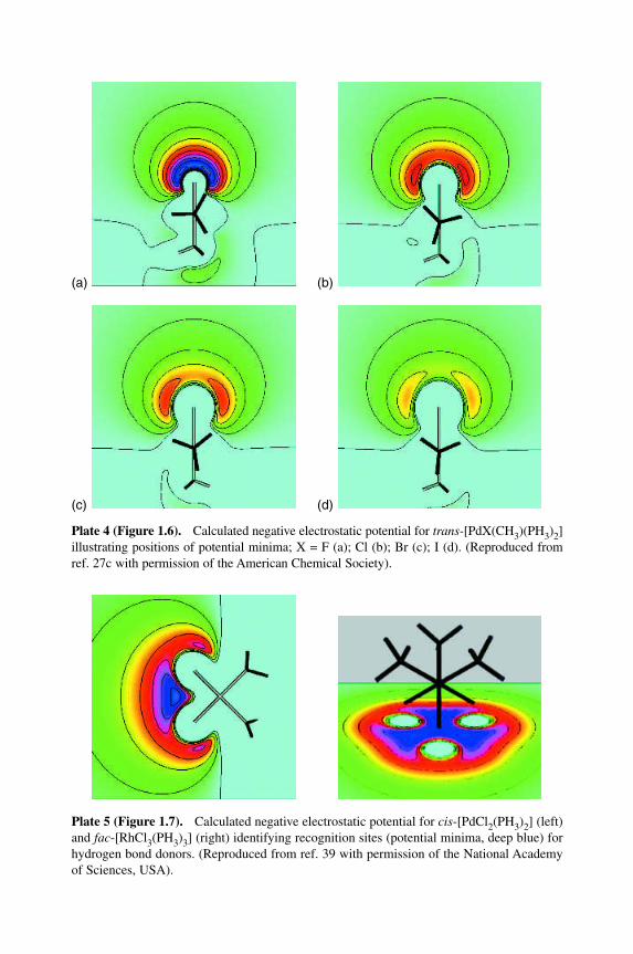
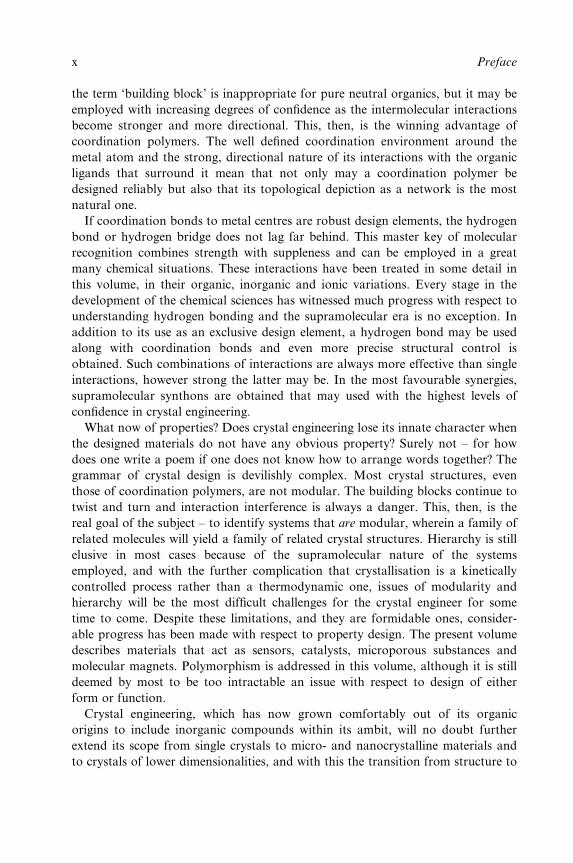
Plate 4 (Figure 1.6).MCalculated negative electrostatic potential for trans-[PdX(CH3)(PH3)2]illustrating positions of potential minima; X = F (a); Cl (b); Br (c); I (d). (Reproduced fromref. 27c with permission of the American Chemical Society).
Plate 5 (Figure 1.7).MCalculated negative electrostatic potential for cis-[PdCl2(PH3)2] (left)and fac-[RhCl3(PH3)3] (right) identifying recognition sites (potential minima, deep blue) forhydrogen bond donors. (Reproduced from ref. 39 with permission of the National Academyof Sciences, USA).
(a) (b)
(c) (d)
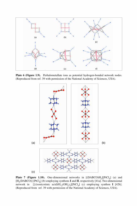
Plate 6 (Figure 1.9).MPerhalometallate ions as potential hydrogen-bonded network nodes.(Reproduced from ref. 39 with permission of the National Academy of Sciences, USA).
Plate 7 (Figure 1.10).MOne-dimensional networks in [(DABCO)H2][PtCl4] (a) and[H2(DABCO)] [PtCl6] (b) employing synthons I and II, respectively [41a]. Two-dimensionalnetwork in [{(isonicotinic acid)H}2(OH2)2][PtCl4] (c) employing synthon I [42b].(Reproduced from ref. 39 with permission of the National Academy of Sciences, USA).
(a) (b)
(c)
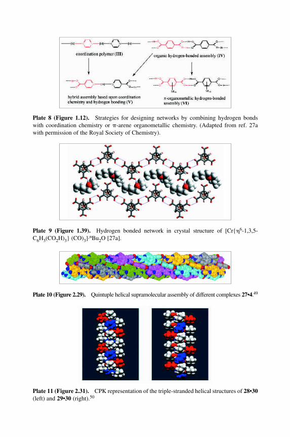
Plate 8 (Figure 1.12).MStrategies for designing networks by combining hydrogen bondswith coordination chemistry or �-arene organometallic chemistry. (Adapted from ref. 27awith permission of the Royal Society of Chemistry).
Plate 9 (Figure 1.39).MHydrogen bonded network in crystal structure of [Cr{�6-1,3,5-C6H3(CO2H)3} (CO)3]·nBu2O [27a].
Plate 10 (Figure 2.29).MQuintuple helical supramolecular assembly of different complexes 27•4.49
Plate 11 (Figure 2.31).MCPK representation of the triple-stranded helical structures of 28•30(left) and 29•30 (right).50
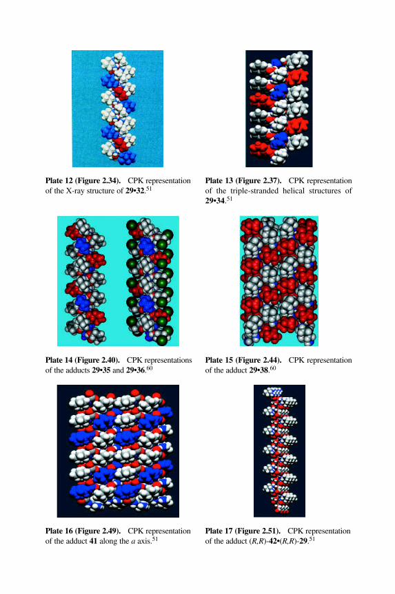
Plate 12 (Figure 2.34).MCPK representationof the X-ray structure of 29•32.51
Plate 14 (Figure 2.40).MCPK representationsof the adducts 29•35 and 29•36.60
Plate 13 (Figure 2.37).MCPK representationof the triple-stranded helical structures of29•34.51
Plate 16 (Figure 2.49).MCPK representationof the adduct 41 along the a axis.51
Plate 15 (Figure 2.44).MCPK representationof the adduct 29•38.60
Plate 17 (Figure 2.51).MCPK representationof the adduct (R,R)-42•(R,R)-29.51
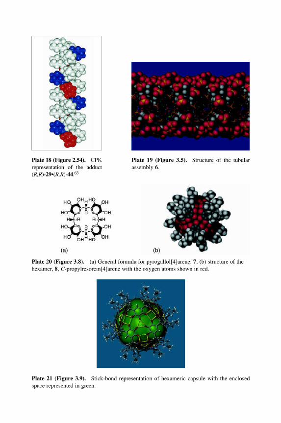
Plate 19 (Figure 3.5).MStructure of the tubularassembly 6.
Plate 20 (Figure 3.8).M(a) General forumla for pyrogallol[4]arene, 7; (b) structure of thehexamer, 8, C-propylresorcin[4]arene with the oxygen atoms shown in red.
(a) (b)
Plate 18 (Figure 2.54).MCPKrepresentation of the adduct(R,R)-29•(R,R)-44.63
Plate 21 (Figure 3.9).MStick-bond representation of hexameric capsule with the enclosedspace represented in green.
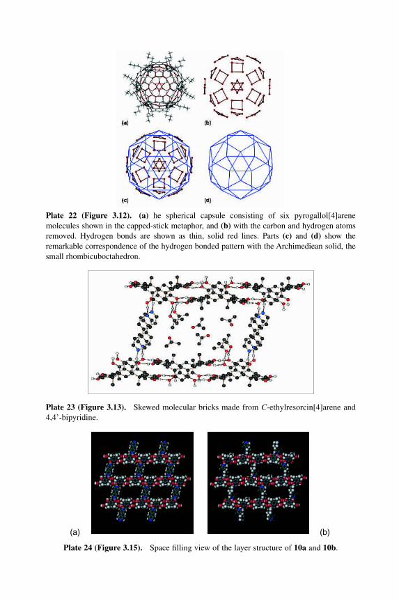
Plate 22 (Figure 3.12).M(a) he spherical capsule consisting of six pyrogallol[4]arenemolecules shown in the capped-stick metaphor, and (b) with the carbon and hydrogen atomsremoved. Hydrogen bonds are shown as thin, solid red lines. Parts (c) and (d) show theremarkable correspondence of the hydrogen bonded pattern with the Archimediean solid, thesmall rhombicuboctahedron.
Plate 23 (Figure 3.13).MSkewed molecular bricks made from C-ethylresorcin[4]arene and4,4’-bipyridine.
Plate 24 (Figure 3.15).MSpace filling view of the layer structure of 10a and 10b.
(a) (b)
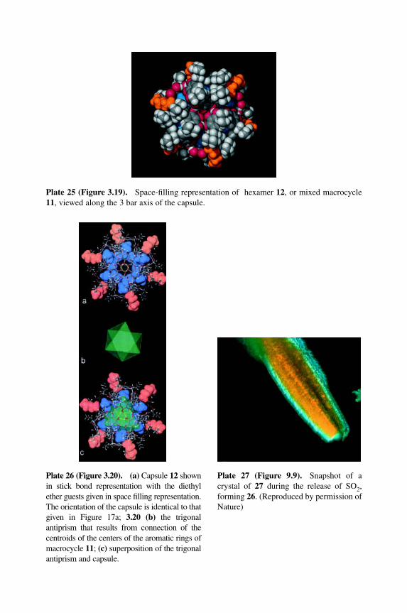
Plate 25 (Figure 3.19).MSpace-filling representation of hexamer 12, or mixed macrocycle11, viewed along the 3 bar axis of the capsule.
Plate 26 (Figure 3.20).M(a) Capsule 12 shownin stick bond representation with the diethylether guests given in space filling representation.The orientation of the capsule is identical to thatgiven in Figure 17a; 3.20 (b) the trigonalantiprism that results from connection of thecentroids of the centers of the aromatic rings ofmacrocycle 11; (c) superposition of the trigonalantiprism and capsule.
Plate 27 (Figure 9.9).MSnapshot of acrystal of 27 during the release of SO2,forming 26. (Reproduced by permission ofNature)
Chapter 1
Hydrogen Bonds in InorganicChemistry: Application to CrystalDesign
LEE BRAMMER
University of Shef®eld, UK
1 INTRODUCTION
The foremost goal of crystal engineering [1] is to tailor the chemical and/or phys-
ical properties of crystalline solids through crystal design at the molecular level.
A detailed modular synthetic strategy is employed permitting control over fabrica-
tion of the solid at the level of the repeating molecular pattern of which the
crystal is comprised. Thus, microscopic control in principle permits macroscopic
tunability of properties. It should of course be acknowledged that crystalline
products may not always represent the most desirable form of a material with
respect to a given function. However, we will concern ourselves only with crystal-
line materials in the context of this volume. Indeed, the focus of this chapter will
be on inorganic crystalline materials, that is, metal-containing systems. Crystalline
materials, of course, can exhibit widespread applications in areas including elec-
tronics, optics and magnetism and have the potential to provide new materials for
use in areas such as separation science, catalysis and chemical sensing [2]. Because
of their regular periodic nature, crystalline solids are amenable to precise struc-
tural characterization by diffraction methods. While characterization by spectro-
scopic methods or the characterization of physical properties (e.g. electronic,
optical, magnetic) is also essential, the importance of accurate and detailed struc-
tural characterization cannot be underestimated. This permits more accurate
Crystal Design: Structure and Function. Volume 7Edited by Gautam R. Desiraju
Copyright 2003 John Wiley & Sons, Ltd.ISBN: 0-470-84333-0
structure±function correlations to be established, a key to the design of functional
or so-called `smart' materials.
The dif®culties associated with synthesis of inorganic materials are captured in
a recent paper by Tulsky and Long [3], who contrast the lack of predictive cap-
ability available using current methodologies with the high degree of predictability
and control over complex systems that has been developed for the synthesis of
organic molecules. Moreover, they reinforce the importance of improving synthetic
control given the intimate link between solid-state structure and properties, as
noted above. Their paper sets forth a well thought out systematic approach,
referred to as dimensional reduction, applicable to the synthesis of a broad class of
inorganic materials. Thus, reaction of binary solids, MXx, with alkali metal salts,
AaX, yields ternary solids AnaMXx�n with the same metal (M) coordination
geometry but lower network dimensionality. Through examination of ca 3000
crystal structures, they have been able to suggest strategies for enforcing some
degree of control of the product ternary structure. Similarly, crystal engineering
seeks to permit controlled synthesis of the crystalline product, though using a
different approach focusing on modular assembly from molecular level building
blocks. Such a modular approach to crystal design requires the use of (neutral or
ionic) building blocks that can be linked in a predictable manner. Thus, a detailed
knowledge of preferred intermolecular interactions is essential, and the study of
such interactions so as to establish geometric preferences and interaction strengths
is a vital part of crystal engineering. Construction of the ®nal crystalline material
is effected by self-assembly of the building blocks through deliberate molecular
recognition between the building blocks. In the conceptually simplest case a
single, self-recognizing building block is used. Two-component systems are also in
widespread use, but the complexity introduced by competing modes of self-assem-
bly rapidly increases the dif®culty presented in the use of multi-component
systems [4].
Crystal engineering has its roots in organic solid-state photochemistry [5], and
indeed in its contemporary guise, wherein it broadly encompasses all aspects
of modular crystal design, the use of organic molecular building blocks linked
via noncovalent interactions has provided the predominant approach [1a]. How-
ever, the past decade, and especially the last 5 years, has seen a tremendous
increase in the number of publications focused on inorganic crystal engineering
[6], broadly de®ned as including metal ions in the supramolecular design in a
structural and/or (potentially) functional role. The introduction of metals, particu-
larly transition metals, has much to offer to the ®eld of crystal engineering. On
the structural side they can provide options for connectivity in the networks
that make up designed crystalline solids that are unavailable in purely organic
systems, viz. square-planar and octahedral coordination geometries. On the func-
tional side, transition metals in particular can impart desirable electronic, optical
or magnetic properties upon the ®nal crystalline material. They also have the
potential to serve as controlled-access reaction sites for catalytic transformations
2 Crystal Design: Structure and Function
in a designed porous solid. In a series of recent reviews focusing on crystal engin-
eering involving metal-containing building blocks linked by intermolecular forces,
Braga and Grepioni have highlighted the special roles that metal ions can play in
in¯uencing the supramolecular assembly of these building blocks [7]. Such roles
include pre-organization of intermolecular interactions through use of speci®c
metal coordination geometries, tuning the ligand polarity or acid±base behaviour
and reinforcement of intermolecular interactions through `charge assistance'
arising from the frequently ionic nature of metal complexes. These aspects will be
elaborated upon in subsequent sections in the context of a domain structure for
metal complexes and through the comparison of inorganic and organic building
blocks.
2 SCOPE AND ORGANIZATION
Despite its youth, inorganic crystal engineering has already yielded an extensive
literature. Thus, it will be necessary to focus the discussion on particular research
avenues. The emphasis in this chapter will be placed upon hydrogen bonds as a
means of connecting the molecular building blocks. An important aspect to con-
sider will be the role of metal atoms. This will require examination of the in¯u-
ence of metals on hydrogen bonding and the potential role of metals in designed
crystalline materials. It should be emphasized at this point that while p-block (i.e.
main group) and f-block (i.e. lanthanides and actinides) metals may be mentioned
occasionally in this chapter, the primary emphasis will be on d-block metals (i.e.
transition metals). Thus, use of the word `metal' throughout this chapter should
be assumed to mean transition metal, unless speci®ed otherwise.
The use of coordination bonds to form networks, so-called coordination poly-
mers, perhaps represents the most widely studied form of inorganic crystal engin-
eering. This approach has also been examined in a number of reviews [8] and is
discussed elsewhere in this volume (see Chapter 5). While coordination chemistry
will have an important role to play in a number of the hydrogen-bonded systems
presented in this chapter, coordination polymers will only be discussed in the
context of their cross-linking or their perturbation using hydrogen bonds.
The importance of analysing and understanding predominant hydrogen
bonding geometries and patterns will be addressed, and in particular the use of
the Cambridge Structural Database (CSD) [9] in obtaining such information. The
use of different hydrogen bond types, the reliability of different means of molecu-
lar recognition between building blocks, viz. supramolecular synthons, and the
similarities and differences between organic and inorganic building blocks will be
discussed. It is not the intent of this review to be comprehensive in terms of
cataloguing all inorganic crystals synthesized by means of molecular building
blocks propagated by hydrogen bonded linkages. However, an effort has been
made to classify the systems currently in the literature and to select illustrative
Hydrogen Bonds: Application to Crystal Design 3
examples from among these. Given the recent development of this research area
the examples are almost exclusively taken from the past 10 years of the literature,
and predominantly from the past 5 years.
There are a number of alternative ways in which this chapter could logically be
organized. A structure has been chosen that places the primary emphasis upon the
strength (and directionality) of different types of hydrogen bonds along with
consideration of their likely abundance, since this re¯ects the likely usefulness of
such hydrogen bonds in crystal engineering. Further divisions have been made by
classifying different types of inorganic building blocks, e.g. based upon coordin-
ation compounds or organometallic compounds. In the later sections an examin-
ation is undertaken of what we might learn from `mistakes' and unpredicted
behaviour in crystal packing. The issue of polymorphism is considered only brie¯y
since it is discussed elsewhere in this volume (see Chapter 8) [10]. The chapter
concludes with sections that examine the extent to which functional inorganic
crystalline materials have been designed and considers the prospects for future
work in this area.
It should be noted that a number of reviews pertinent to the coverage within
this chapter can be found either considering hydrogen bonding in inorganic
or organometallic crystal engineering [7,11] or focusing on other aspects of hydro-
gen bonding in inorganic chemistry such as the direct involvement of metals
in hydrogen bonds [12] or the formation of `dihydrogen' (proton±hydride)
bonds [13].
3 HYDROGEN BONDS
3.1 De®nitions
Given the focus on hydrogen bonding in inorganic crystal design, the question
of what constitutes a hydrogen bond needs to be addressed, as does the question
of how hydrogen bonding may differ in inorganic and organic systems. All texts
on hydrogen bonds address the issue of how to de®ne them [14], although de®n-
itions vary in their degree of inclusiveness. A broad and inclusive de®nition will be
adopted here, wherein a hydrogen bond, D±H � � �A, requires a hydrogen bond
donor (D) that forms a polar s-bond with hydrogen (D±H) in which the hydro-
gen atom carries a partial positive charge. This group interacts via the hydrogen
atom in an attractive manner with at least one acceptor atom or group (A) by
virtue of a lone pair of electrons or other accumulation of electron density on
the acceptor. Thus, a hydrogen bond is a Lewis acid±Lewis base interaction,
wherein D±H serves as the Lewis acid and A as the Lewis base. Limitations will
not be placed, a priori, on the identities of the donor and acceptor atoms (groups).
Thus, all hydrogen bond types, i.e. donor and acceptor combinations, will be
considered given the limitation (in the context of this chapter) that inorganic,
4 Crystal Design: Structure and Function
i.e. metal-containing molecules, must be involved, and that the system being
discussed is pertinent in the context of crystal design. The question of
how hydrogen bonds may differ in the context of inorganic rather than organic
systems requires consideration of the in¯uence of metal atoms on hydrogen
bonding and even requires the introduction of classes of hydrogen bonds
absent in a purely organic environment. These issues are addressed in Sections 3.3
and 3.4.
Hydrogen bonds exhibit a well-documented energetic preference for a linear
D±H � � �A geometry and are arguably the strongest and most directional of
noncovalent interactions. Hydrogen bonds with strengths in the range ca
0.2±40 kcal/mol are known, although not all are of signi®cant importance in the
context of crystal design. Hydrogen bonds are also ¯exible, in terms of both
hydrogen bond length and geometry. It is for these combined reasons of strength,
directionality and ¯exibility that hydrogen bonds are important to inorganic
crystal engineering just as they are in organic crystal engineering [1,15] and for
that matter to other structural ®elds such as structural biology [14c,e].
Returning now to terminology in use speci®cally in the ®eld of crystal engineer-
ing, an important conceptual advance was the de®nition of so-called supramolecu-
lar synthons by Desiraju [16]. These are structure-directing recognition motifs
involving noncovalent interactions. The intent is that they can be identi®ed and
used in supramolecular synthesis in a conceptually analogous manner to the use of
synthons in the (covalent) synthesis of organic molecules [17]. Some examples [18]
are provided in Section 3.2
3.2 Strong vs Weak Hydrogen Bonds
In considering the use of hydrogen bonds in inorganic crystal engineering, it is
important to establish the applicability of different classes of hydrogen bonds.
This will depend upon hydrogen bond strength, the reliability of hydrogen-
bonded recognition motifs and how abundant or attainable the particular hydro-
gen bonds may be. While many texts classify hydrogen bonds as `strong' and
`weak', the borderline between these classes, usually delineated in terms of hydro-
gen bond energies, often varies depending on the context in which hydrogen
bonding is being discussed. The classi®cations provided by Desiraju and Steiner
[14e], which are assigned in the context of the utility of hydrogen bonds in supra-
molecular chemistry, will be adopted here. These are documented in Table 1. The
terms `very strong', `strong' and `weak' hydrogen bond will be used in this frame
of reference throughout the chapter.
Hydrogen bond types that are widely used in organic crystal engineering, pri-
marily D±H � � �A where D, A � O or N, will inevitably be important in inorganic
systems since the same functional groups that form such hydrogen bonds, i.e.
carboxyl, amide, oxime, alcohol, amine, etc., can be present as part of organic
Hydrogen Bonds: Application to Crystal Design 5

Table 1 Classification and properties of hydrogen bonds, D±H � � �A. # G. R. Desirajuand T. Steiner, 1999. Adapted from Table 1.5 in The Weak Hydrogen Bond in Structural
Chemistry and Biology by Gautam R. Desiraju and Thomas Steiner (1999) by permissionof Oxford University Press.
Very strong Strong Weak
Bond energy (kcal/mol) 15±40 4±15 < 4Examples [F � � �H � � �F]ÿ O±H � � �Oww
C C±H � � �O[N � � �H � � �N]� N±H � � �Oww
C N±H � � �F±CP±OH � � �Oww
P O±H � � �O±H O±H � � �pIR ns relative shift (%) > 25 5±25 < 5Bond lengths D±H � H � � �A D±H < H � � �A D±H� H � � �ALengthening of D±H (AÊ ) 0.05±0.2 0.01±0.05 � 0:01D � � �A range (AÊ ) 2.2±2.5 2.5±3.0 3.0±4.5H � � �A range (AÊ ) 1.2±1.5 1.5±2.2 2.2±3.5Bonds shorter than H � � �A
vdW separation (%)100 Almost 100 30±80
D±H � � �A angles range (8) 175±180 130±180 90±180Effect on crystal packing Strong Distinctive VariableUtility in crystal engineering Unknown Useful Partly usefulCovalency Pronounced Weak VanishingElectrostatic contribution Significant Dominant Moderate
ligands used in metal-containing building blocks. These are strong hydrogen
bonds (ca 4±15 kcal/mol) when formed between neutral ligands but can be
stronger still when involving ionic species due to the additional electrostatic at-
traction between the ions, often referred to as `charge-assistance' [1b,7]. Strong
hydrogen bonds can be effective at directing association of building blocks and
are therefore very valuable in crystal engineering. This is particularly so when
they are part of reliable supramolecular synthons, some examples of which are
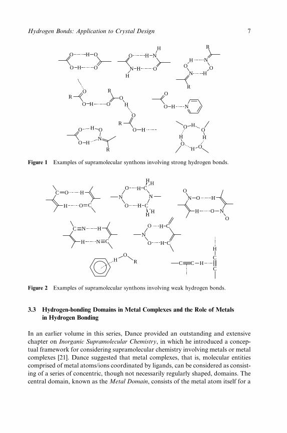
provided in Figure 1.
The importance of weak hydrogen bonds (< 4 kcal/mol), particularly those
involving C±H donor groups, has been established and is recognized to be of
importance in crystal engineering. The sheer abundance of C±H donor groups in
organic compounds and thus organic ligands necessitates that C±H � � �A hydrogen
bonds (particularly A � O, N) must be considered. Such hydrogen bonds often
provide support, i.e. play a secondary role, to stronger hydrogen bonds. In sup-
port of this notion, AakeroÈy and Leinen note that `C±H � � �X interactions can tilt
the balance between several options of stronger bonded networks, thus acting as
an important ``steering force'' in the solid-state assembly' [19]. In fact, in the
absence of stronger intermolecular interactions weak hydrogen bonds can be used
to direct crystal design [20]. Indeed, many supramolecular synthons based upon
weak hydrogen bonds have been identi®ed, as illustrated in Figure 2. In many
cases these are topologically analogous to supramolecular synthons that use
strong hydrogen bonds.
6 Crystal Design: Structure and Function
O
O
H
H
O
O
O
N
H
H
N
O
H
H
R
NO
H
HO
N
R
O
O H
H O
N
RO
H
O HOH
H O
O
O H N
O
O HR
R
OO
H
O
RO H
Figure 1 Examples of supramolecular synthons involving strong hydrogen bonds.
H
O C
C O
H
H
N C
C N
H
N
C
C
H
H
H
HH
O
N
O
H
OH
N OO
N
H
O
O
N
O
H
H
C
C
C
C
H
C C HH
OR
Figure 2 Examples of supramolecular synthons involving weak hydrogen bonds.
3.3 Hydrogen-bonding Domains in Metal Complexes and the Role of Metals
in Hydrogen Bonding
In an earlier volume in this series, Dance provided an outstanding and extensive
chapter on Inorganic Supramolecular Chemistry, in which he introduced a concep-
tual framework for considering supramolecular chemistry involving metals or metal
complexes [21]. Dance suggested that metal complexes, that is, molecular entities
comprised of metal atoms/ions coordinated by ligands, can be considered as consist-
ing of a series of concentric, though not necessarily regularly shaped, domains. The
central domain, known as the Metal Domain, consists of the metal atom itself for a
Hydrogen Bonds: Application to Crystal Design 7
mononuclear complex or a number of metal atoms if a metal cluster complex is being
considered. Working outwards, next comes the Ligand Domain. This consists of the
ligand atoms that surround the metal centre(s). The Periphery Domain, as its name
suggests, is the outermost part of the complex, i.e. ligand atoms that are in a position
to interact with the molecular surroundings, termed the Environment Domain. The
Environment Domain consists of neighbouring molecules in the solid state, and
would be comprised primarily of solvent molecules in solution phase supramolecular
chemistry. Ligand atoms in the Periphery Domain are often, but not necessarily,
remote from the metal centre(s). Herein a point of ambiguity arises in the de®nition
of the Ligand and Periphery Domains. Thus, for very simple (e.g. monoatomic) lig-
ands, the ligand atoms might be considered to simultaneously occupy both domains.
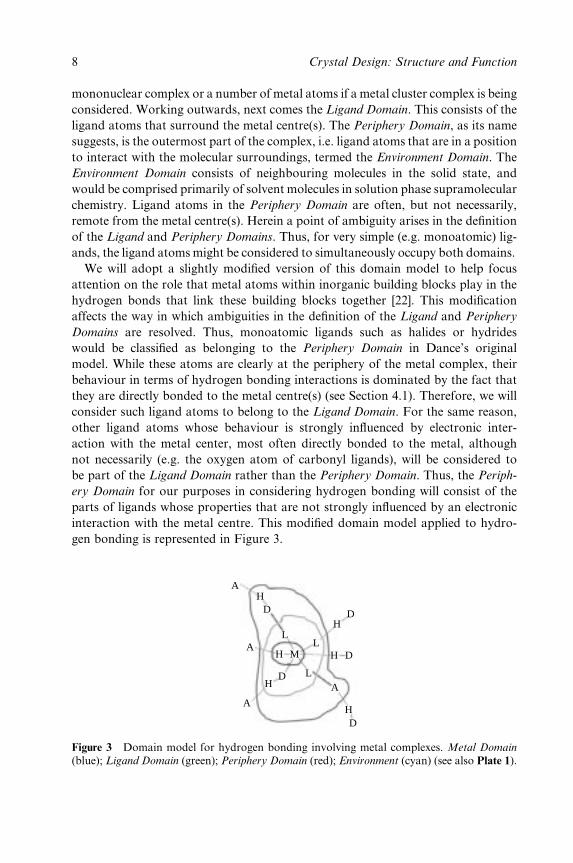
We will adopt a slightly modi®ed version of this domain model to help focus
attention on the role that metal atoms within inorganic building blocks play in the
hydrogen bonds that link these building blocks together [22]. This modi®cation
affects the way in which ambiguities in the de®nition of the Ligand and Periphery
Domains are resolved. Thus, monoatomic ligands such as halides or hydrides
would be classi®ed as belonging to the Periphery Domain in Dance's original
model. While these atoms are clearly at the periphery of the metal complex, their
behaviour in terms of hydrogen bonding interactions is dominated by the fact that
they are directly bonded to the metal centre(s) (see Section 4.1). Therefore, we will
consider such ligand atoms to belong to the Ligand Domain. For the same reason,
other ligand atoms whose behaviour is strongly in¯uenced by electronic inter-
action with the metal center, most often directly bonded to the metal, although
not necessarily (e.g. the oxygen atom of carbonyl ligands), will be considered to
be part of the Ligand Domain rather than the Periphery Domain. Thus, the Periph-
ery Domain for our purposes in considering hydrogen bonding will consist of the
parts of ligands whose properties that are not strongly in¯uenced by an electronic
interaction with the metal centre. This modi®ed domain model applied to hydro-
gen bonding is represented in Figure 3.
AH
D
L
H D
D
D
D
H
H
H
H
MA
A
A
L
L
Figure 3 Domain model for hydrogen bonding involving metal complexes. Metal Domain
(blue); Ligand Domain (green); Periphery Domain (red); Environment (cyan) (see also Plate 1).
8 Crystal Design: Structure and Function
Hydrogen bonding involving the Metal Domain requires that the metal (M) itself
is part of the hydrogen bond, either as the hydrogen bond donor, M±H � � �A [23],
or more commonly as the acceptor, i.e. D±H � � �M [24,25]. Such interactions are of
necessity peculiar to inorganic systems, but while they may have some applications
in crystal engineering these are likely to be very limited. This is not an issue of lack
of strength of these interactions. Indeed, O±H � � �M hydrogen bonds between neu-
tral species have been measured at up to 7 kcal/mol [25e]. Rather, the issue is that
D±H � � �M hydrogen bonds are limited to speci®c types of metal complex in which
sterically accessible ®lled metal-based orbitals are present. M±H � � �A hydrogen
bonds are rarer still. Hydrogen bonds in the Metal Domain are discussed in more
detail in Section 6.
Hydrogen bonding in the Ligand Domain infers that hydrogen bond donor (D)
or acceptor atoms (A) are directly bonded to metal centres or have strong elec-
tronic interactions with metal centres, e.g. M±D±H � � �A or D±H � � �A±M. Metals
can exert an electronic in¯uence upon hydrogen bonds formed in this domain.
Thus, the acidity of hydrogen bond donors and the basicity of hydrogen bond
acceptors can be tuned via their coordination to metal centres. A good example,
often taught in introductory undergraduate chemistry courses, is that water mol-
ecules become more acidic when coordinated to metals. Of course, such water
molecules necessarily become stronger hydrogen bond donors. On the acceptor
side, it has also been shown that halogens are excellent hydrogen bond acceptors
when bound to transition metals (as metal halides) in contrast to their limited
ability to serve as very weak hydrogen bond acceptors when bound to carbon (as
halocarbons) [26]. Here it is the greater polarity of the M±X bond (Md�±Xdÿ)
relative to the C±X bond that is important. Coordination to a metal gives rise to
a greater accumulation of negative charge on the halogen, thus enhancing its
hydrogen bond acceptor capability. The importance of Ligand Domain hydrogen
bonding in crystal engineering will be discussed in more detail in Section 4.1 and
parts of Sections 4.3, 4.4 and 5.
In the Periphery Domain, hydrogen bonding involves organic functional groups
associated with the ligands. The electronic in¯uence of the metal centre is small and
would typically depend upon the extent of through-ligand orbital overlap (conjuga-
tion) between the metal centre and the peripheral hydrogen bonding groups. How-
ever, the metal can still exert a spatial role in directing the hydrogen bonds. Thus,
coordination of rigid ligands with hydrogen bonding groups at their periphery to a
metal ion of well-de®ned coordination geometry can be used to direct hydrogen
bond formation between neighbouring molecules [27]. One can consider the ligands
as effectively amplifying the metal coordination geometry. The result in terms of
network design is analogous to that of coordination polymers (networks), except
that discrete molecular building blocks (coordination compounds) are linked via
well-de®ned hydrogen bonds. In terms of inorganic crystal engineering, hydrogen
bonds in the periphery domain account for the majority of systems studied to date.
These systems are examined in Section 4.2 and parts of Sections 4.3, 4.4 and 5.
Hydrogen Bonds: Application to Crystal Design 9
3.4 Similarities and Differences Between Inorganic and Organic Crystal
Engineering
In a valuable series of studies, Braga, Grepioni, Desiraju and co-workers have
examined patterns of hydrogen bonds in transition metal-containing crystal struc-
tures using the CSD [23e,25j,28]. These studies explore the similarities and differ-
ences between hydrogen bonds found in purely organic crystals and those found in
inorganic systems. Thus, it is noted that hydrogen bonding patterns for carboxyl,
alcohol and amide groups in crystals of metal complexes are similar to those in
organic crystals [28a,c]. Importantly, this con®rms that such functional groups,
which when present typically will be in the Periphery Domain of metal complexes,
can be used in inorganic crystal engineering in an analogous manner to their wide-
spread use in the design and synthesis of organic crystals. Carbonyl ligands, which
can serve as hydrogen bond acceptors, albeit weaker than their organic carbonyl
counterparts, are abundant in organometallic compounds [11a]. However, while
the carbonyl oxygen atoms can accept hydrogen bonds from strong hydrogen bond
donors (O±H, N±H), it is the predominance of peripheral C±H groups that leads to
the widespread importance of C±H � � �OwwwC(M) hydrogen bonds in organometallic
crystals [28b]. This topic will be taken up in Sections 4.1.4 and 5.
Clearly speci®c to inorganic systems are hydrogen bonds that directly involve
metal atoms, M±H � � �A and D±H � � �M, i.e. those in the Metal Domain. A survey
of crystal structures has illustrated that M±H � � �O hydrogen bonds appear to
resemble C±H � � �O hydrogen bonds, although the former are of course far less
abundant. The extent to which such hydrogen bonds may be useful in crystal
engineering is addressed in Section 6.
Hydrogen bond acceptors found in the Ligand Domain are in a number of cases
peculiar to inorganic systems in that it is the electronic in¯uence of coordination
to the metal centre that activates these ligands towards hydrogen bonding. Excel-
lent examples are metal halides (M±X) and metal hydrides (M±H), both of which
can serve as strong hydrogen bond acceptors, in contrast to their organic counter-
parts, C±X and C±H. The application of M±X and M±H acceptors in crystal
engineering is discussed in Sections 4.1.2 and 4.1.3, respectively.
3.5 Abundant vs Rare Hydrogen Bonds ± Their Importance in Crystal
Engineering
The strength of hydrogen bonds and their ability to contribute to reliable supra-
molecular synthons are not the only criteria for judging the importance of differ-
ent types of hydrogen bonds. Unless such hydrogen bonds are readily accessible,
they will inevitably be of limited use, although perhaps of use in specialized cases.
This will inevitably be the case with M±H � � �A and D±H � � �M hydrogen bonds,
which are only accessible for certain classes of metal complex. At the other
10 Crystal Design: Structure and Function
extreme are C±H � � �A hydrogen bonds, especially C±H � � �O. These are abundant
in the crystal structures of many organometallic and coordination compounds and
clearly play an important overall role in crystal cohesion and the overall optimiza-
tion of the interactions between molecular units in a crystalline solid. Their weak-
ness makes them more dif®cult to use in crystal design than stronger hydrogen
bonds. However, their abundance ensures that they cannot be ignored. Indeed,
not only do they guide the stronger intermolecular interactions in the crystal, as
noted previously, but they can in some cases completely overwhelm stronger
interactions as a result of their relative abundance [11d].
3.6 Analysis of Hydrogen Bonding Using the Cambridge Structural Database
The importance of identifying preferred hydrogen bond geometries, supramolecu-
lar synthons and packing arrangements in planning a crystal synthesis strategy
based upon hydrogen-bonded building blocks is, of course, essential. The CSD [9]
contains crystallographic data for all organic and organometallic crystal structures
(245 392 crystal structures as of October 1, 2001). These data, combined with the
search and data analysis tools that accompany the database, make it a veritable
treasure trove of information that is invaluable to anyone considering research in
the area of crystal engineering. It is unfortunate that the practice of `data mining',
the term sometimes applied to the derivation of trends from information stored in
databases, is considered by some not to be original research. Such a short-sighted
viewpoint fails to recognize that important and unanticipated trends inaccessible by
examination of individual systems can only be identi®ed by such means. Such
analyses using crystallographic databases, particularly the CSD in the present con-
text of hydrogen-bonded inorganic structures, are a vital part of crystal engineering
and clearly help to lay the groundwork for crystal design strategies.
4 STRONG, STRUCTURE-DIRECTING HYDROGEN BONDS
Section 4 emphasizes the use in inorganic crystal engineering of strong donor
groups, i.e. O±H or N±H, that can form hydrogen bonds with energies typically
in the 4±15 kcal/mol range depending on the acceptor group employed. Such
groups are common constituents of organic functional groups and thus can be
incorporated into a wide range of inorganic building blocks based upon coordin-
ation compounds or organometallic compounds.
4.1 Ligand Domain
In the systems discussed in Section 4.1, the dominant role of the metal in terms of
hydrogen bond formation arises form its strong electronic in¯uence upon the
donor or acceptor ability of the groups participating in hydrogen bonding.
Hydrogen Bonds: Application to Crystal Design 11
4.1.1 Donors: (M)O±H and (M)N±H
Here we consider hydrogen bonds donated by coordinated ligands such as
hydroxyl (OH), water (OH2), alcohols (ROH) and amines (NH3, NRH2, NR2H).
The in¯uence of coordination to a metal centre (M) on hydrogen donor OH2 has
already been commented upon (Section 3.3). Each of these ligands is a net elec-
tron donor to the metal centre (principally s-donation). Thus, one should antici-
pate that coordination of the oxygen or nitrogen atom to a metal centre will result
in increased polarity of the O±H or N±H bond, thus increasing the potency of the
ligand as a hydrogen bond donor.
While this class of ligands participates extensively in hydrogen bonding, the
application of such ligands in crystal synthesis has to date been somewhat limited.
A common theme is one of using these ligands to form hydrogen bonds to a spacer
molecule or anion that permits metal centres to be linked into networks. This
approach presumably arises as a result of the small size of these ligands. In an early
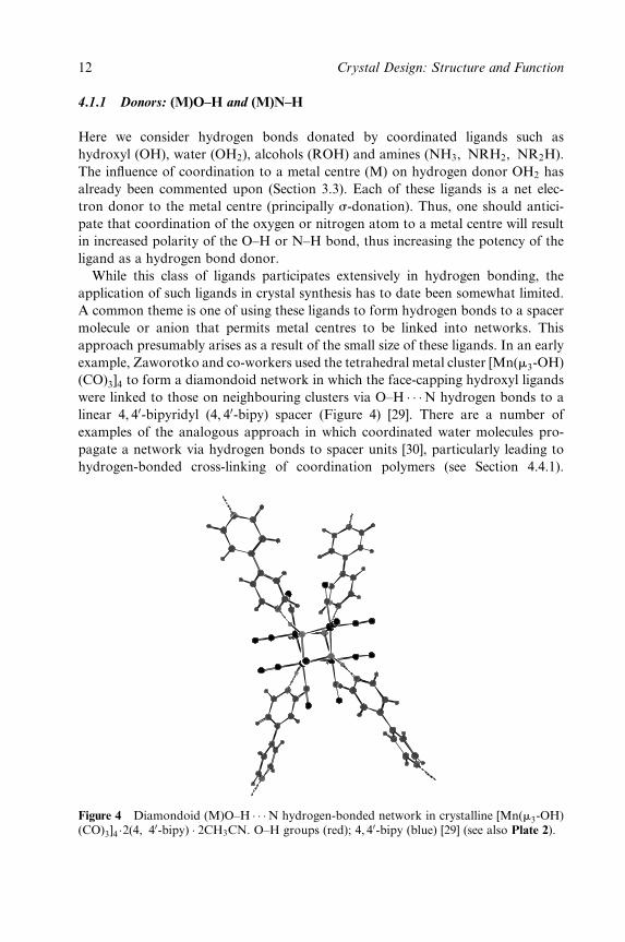
example, Zaworotko and co-workers used the tetrahedral metal cluster [Mn(m3-OH)
(CO)3]4 to form a diamondoid network in which the face-capping hydroxyl ligands
were linked to those on neighbouring clusters via O±H � � �N hydrogen bonds to a
linear 4, 40-bipyridyl (4, 40-bipy) spacer (Figure 4) [29]. There are a number of
examples of the analogous approach in which coordinated water molecules pro-
pagate a network via hydrogen bonds to spacer units [30], particularly leading to
hydrogen-bonded cross-linking of coordination polymers (see Section 4.4.1).
Figure 4 Diamondoid (M)O±H � � �N hydrogen-bonded network in crystalline [Mn(m3-OH)(CO)3]4 �2(4, 40-bipy) � 2CH3CN. O±H groups (red); 4, 40-bipy (blue) [29] (see also Plate 2).
12 Crystal Design: Structure and Function
Taking the idea one step further, in [(4, 40-bipy)H2]2[Ni(OH2)2(NCS)4][NO3]2,
Chen and co-workers prepared a three-component hydrogen-bonded `chicken
wire' 2D grid network wherein coordinated water molecules form hydrogen
bonds to nitrate anions, which in turn are hydrogen-bonded to the 4, 40-bipyridi-
nium cations 30e (see Section 4.3.1). Since alcohols are weaker ligands than hy-
droxide or water, it is likely that they will be less effective for use in crystal design,
although there are many examples in which networks are propagated due to
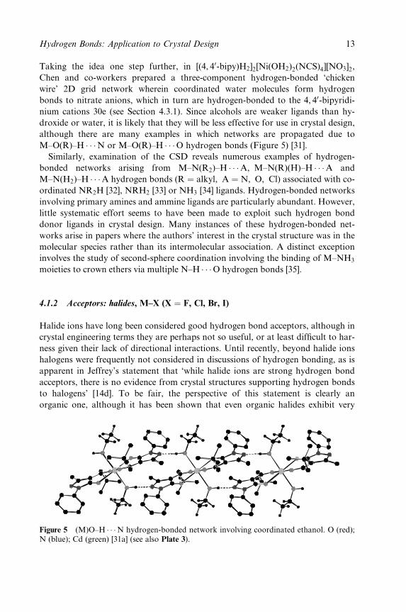
M±O(R)±H � � �N or M±O(R)±H � � �O hydrogen bonds (Figure 5) [31].
Similarly, examination of the CSD reveals numerous examples of hydrogen-
bonded networks arising from M±N(R2)±H � � �A, M±N(R)(H)±H � � �A and
M±N(H2)±H � � �A hydrogen bonds (R � alkyl, A � N, O, Cl) associated with co-
ordinated NR2H [32], NRH2 [33] or NH3 [34] ligands. Hydrogen-bonded networks
involving primary amines and ammine ligands are particularly abundant. However,
little systematic effort seems to have been made to exploit such hydrogen bond
donor ligands in crystal design. Many instances of these hydrogen-bonded net-
works arise in papers where the authors' interest in the crystal structure was in the
molecular species rather than its intermolecular association. A distinct exception
involves the study of second-sphere coordination involving the binding of M±NH3
moieties to crown ethers via multiple N±H � � �O hydrogen bonds [35].
4.1.2 Acceptors: halides, M±X (X � F, Cl, Br, I)
Halide ions have long been considered good hydrogen bond acceptors, although in
crystal engineering terms they are perhaps not so useful, or at least dif®cult to har-
ness given their lack of directional interactions. Until recently, beyond halide ions
halogens were frequently not considered in discussions of hydrogen bonding, as is
apparent in Jeffrey's statement that `while halide ions are strong hydrogen bond
acceptors, there is no evidence from crystal structures supporting hydrogen bonds
to halogens' [14d]. To be fair, the perspective of this statement is clearly an
organic one, although it has been shown that even organic halides exhibit very
Figure 5 (M)O±H � � �N hydrogen-bonded network involving coordinated ethanol. O (red);N (blue); Cd (green) [31a] (see also Plate 3).
Hydrogen Bonds: Application to Crystal Design 13
weak hydrogen bond acceptor behaviour [20a,26c,36]. In 1998, Brammer, Orpen
and co-workers pointed out that contrary to the behaviour of carbon-bound chlor-
ine, their metal-bound counterparts (i.e. inorganic chlorides) are good hydrogen
bond acceptors [26a]. This arises from the greater polarity of M±Cl bonds relative to
C±Cl bonds, leading to a much stronger electrostatic component for D±H � � �Cl±M
hydrogen bonds than for the D±H � � �Cl±C case. These conclusions have since been
generalized for all halogens through extensive studies using the CSD and based
upon data from thousands of interactions involving halogens [26b,c]. Most pertin-
ent to inorganic chemistry, geometric preferences and trends of D±H � � �X±M
hydrogen bonds (D � O, N, C; X � F, Cl, Br, I) have been established. These
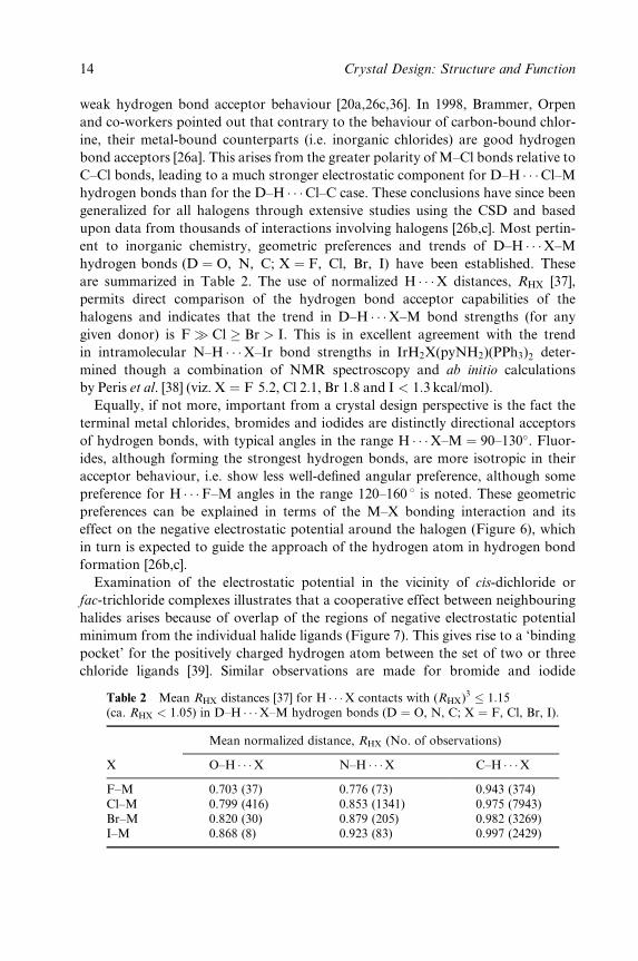
are summarized in Table 2. The use of normalized H � � �X distances, RHX [37],
permits direct comparison of the hydrogen bond acceptor capabilities of the
halogens and indicates that the trend in D±H � � �X±M bond strengths (for any
given donor) is F� Cl � Br > I. This is in excellent agreement with the trend
in intramolecular N±H � � �X±Ir bond strengths in IrH2X(pyNH2)(PPh3)2 deter-
mined though a combination of NMR spectroscopy and ab initio calculations
by Peris et al. [38] (viz. X � F 5:2, Cl 2.1, Br 1.8 and I < 1:3 kcal/mol).
Equally, if not more, important from a crystal design perspective is the fact the
terminal metal chlorides, bromides and iodides are distinctly directional acceptors
of hydrogen bonds, with typical angles in the range H � � �X±M � 90±130�. Fluor-
ides, although forming the strongest hydrogen bonds, are more isotropic in their
acceptor behaviour, i.e. show less well-de®ned angular preference, although some
preference for H � � �F±M angles in the range 120±160 8 is noted. These geometric
preferences can be explained in terms of the M±X bonding interaction and its
effect on the negative electrostatic potential around the halogen (Figure 6), which
in turn is expected to guide the approach of the hydrogen atom in hydrogen bond
formation [26b,c].
Examination of the electrostatic potential in the vicinity of cis-dichloride or
fac-trichloride complexes illustrates that a cooperative effect between neighbouring
halides arises because of overlap of the regions of negative electrostatic potential
minimum from the individual halide ligands (Figure 7). This gives rise to a `binding
pocket' for the positively charged hydrogen atom between the set of two or three
chloride ligands [39]. Similar observations are made for bromide and iodide
Table 2 Mean RHX distances [37] for H � � �X contacts with (RHX)3 � 1:15(ca. RHX < 1:05) in D±H � � �X±M hydrogen bonds (D � O, N, C; X � F, Cl, Br, I).
Mean normalized distance, RHX (No. of observations)
X O±H � � �X N±H � � �X C±H � � �XF±M 0.703 (37) 0.776 (73) 0.943 (374)Cl±M 0.799 (416) 0.853 (1341) 0.975 (7943)Br±M 0.820 (30) 0.879 (205) 0.982 (3269)I±M 0.868 (8) 0.923 (83) 0.997 (2429)
14 Crystal Design: Structure and Function

(a) (b)
(c) (d)
Figure 6 Calculated negative electrostatic potential for trans-[PdX(CH3)(PH3)2] illustrat-ing positions of potential minima; X � F (a); Cl (b); Br (c); I (d). Reprinted with permissionfrom L. Brammer, E. A. Bruton and P. Sherwood, Cryst. Growth Des., 1, 277±90 (2001).Copyright 2001 American Chemical Society (see also Plate 4).
Figure 7 Calculated negative electrostatic potential for cis-[PdCl2(PH3)2] (left) andfac-[RhCl3(PH3)3] (right) identifying recognition sites (potential minima, deep blue) forhydrogen bond donors. Reproduced with permission from L. Brammer, J. K. Swearingen,E.A. Bruton and P. Sherwood, Proc. Natl. Acad. Sci. USA, 99, 4956±61 (2002). Copyright2002 National Academy of Sciences, USA (see also Plate 5).
Hydrogen Bonds: Application to Crystal Design 15
ligands, while cooperativity is less pronounced for the more isotropic ¯uoride
ligands [40]. In crystal engineering terms, this directly con®rms the importance of
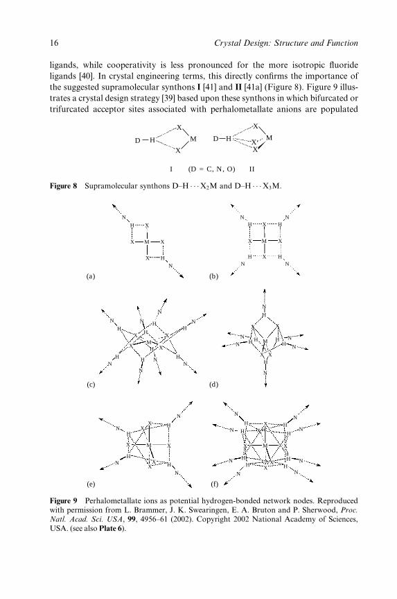
the suggested supramolecular synthons I [41] and II [41a] (Figure 8). Figure 9 illus-
trates a crystal design strategy [39] based upon these synthons in which bifurcated or
trifurcated acceptor sites associated with perhalometallate anions are populated
(D = C, N, O)I II
H M
X
XD H X
M
X
X
D
Figure 8 Supramolecular synthons D±H � � �X2M and D±H � � �X3M.
N
N N
N
N
NN
N
N
N
N
N
N
N NN
N
N
N
N
N
N
N
N N
N
N
N
N
N
N
X X
X
X
X X
X
X
XX
X
X
X
X
X
X X
X
H XX
X
X
X
X
X
H H
H
H
HHH H
H
H
H
HHH
H
HH
H
H
H
H
H
H
X
X
XM M
M
MM
M
H
H HH
H
NHH H
(a)
(c)
(e)
(b)
(d)
(f)
Figure 9 Perhalometallate ions as potential hydrogen-bonded network nodes. Reproducedwith permission from L. Brammer, J. K. Swearingen, E. A. Bruton and P. Sherwood, Proc.
Natl. Acad. Sci. USA, 99, 4956±61 (2002). Copyright 2002 National Academy of Sciences,USA. (see also Plate 6).
16 Crystal Design: Structure and Function
by hydrogen bonds, permitting the anions to serve as nodes in a hydrogen-bonded
network. Thus, in square-planar anions [MX4]nÿ only (bifurcated) edge acceptor
sites are available, whereas in octahedral [MX6]nÿ anions, both edge sites and
(trifurcated) face sites are accessible, the latter being slightly preferred. Less coop-
erativity between halogens arises in tetrahedral [MX4]nÿ anions since the halide
ligands are further apart, and hydrogen bonds are frequently asymmetrically bifur-
cated at one edge of the tetrahedron. This approach has been applied to the design
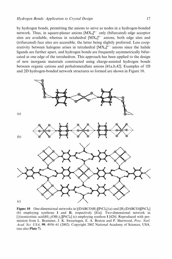
of new inorganic materials constructed using charge-assisted hydrogen bonds
between organic cations and perhalometallate anions [41a,b,42]. Examples of 1D
and 2D hydrogen-bonded network structures so formed are shown in Figure 10.
(a)
(b)
(c)
Figure 10 One-dimensional networks in [(DABCO)H2][PtCl4] (a) and [H2(DABCO)][PtCl6](b) employing synthons I and II, respectively [41a]. Two-dimensional network in[{(isonicotinic acid)H}2(OH2)2][PtCl4] (c) employing synthon I [42b]. Reproduced with per-mission from L. Brammer, J. K. Swearingen, E. A. Bruton and P. Sherwood, Proc. Natl.
Acad. Sci. USA, 99, 4956±61 (2002). Copyright 2002 National Academy of Sciences, USA.(see also Plate 7).
Hydrogen Bonds: Application to Crystal Design 17
In their work in this area, Orpen and co-workers have sought to prepare hydro-
gen-bonded halometallate salts using the planar 4, 40-bipyridinium dication
[41b,42]. They note that while synthon I results from combination with the
square-planar [MCl4]2ÿ anion, neither synthon I nor II arises when tetrahedral
[MCl4]2ÿ or octahedral [MCl6]
2ÿ anions are used, in contrast to the use of the
[H2(DABCO)]2� cation by Brammer et al. Importantly, however, their studies
indicate that all of the 4, 40-bipyridinium structures can be rationalized as
belonging to a larger homologous family of salts that include chloride and a
variety of chlorometallates as counteranions [42c]. All form structures based upon
ribbon motifs containing NH � � � (Cl)2 � � �HN interactions, into which synthon I
can be accommodated, but is not required.
These hydrogen-bonded salts show distinct potential for the controlled design
of new crystalline structures, and are applicable to incorporation of a wide variety
of transition metal and main group metal ions. The work of Mitzi on perovskite
structures in which perhalometallate layers are linked via organic alkyl ammo-
nium cations that interact via N±H � � �X±M hydrogen bonds shows another area
of potential application [43] (see Sections 4.4.2 and 7).
Finally, it should be noted that there are many examples, some designed deliber-
ately [44], in which ligands bearing peripheral hydrogen bond donor groups have
been coordinated to metals that bear a halide (often chloride) ligand, resulting in a
1D hydrogen-bonded tape [44]. In particular, an abundance of compounds of the
type cis-MCl2L2(L � amine) have been crystallographically characterized as a
result of research spawned by the discovery of anti-tumour agent cisplatin,
cis-[PtCl2(NH3)2]. These systems provide abundant information on neutral hydro-
gen-bonded networks propagated by N±H � � �Cl±M hydrogen bonds.
4.1.3 Acceptors: hydrides (D±H � � �H±M and D±H � � �H±E, E � B, Al, Ga)
The realization that hydridic hydrogen can serve as a hydrogen bond acceptor
came about through work by the groups of Crabtree and Morris on transition
metal hydrides in the mid-1990s [45]. It was subsequently established that main
group hydrides, particularly from Group 3, formed analogous D±H � � �H±E (E �B, Al, Ga) hydrogen bonds [46]. This class of hydrogen bonds has been studied for
its role in facilitating chemical reactions [47] and more recently with respect to
applications in the area of crystal engineering. Thus, Morris and co-workers
designed 1D hydrogen-bonded polymers propagated solely or at least in part by
charge-assisted N±H � � �H±M hydrogen bonds [48]. These systems involve hydro-
gen bond donor cations, comprising K� ions encapsulated by azacrown ethers,
combined with polyhydridometallate anions, as shown in Figure 11. There are
clearly some analogies between these systems and the hydrogen-bonded halometal-
late salts (see above). Gladfelter and co-workers [46h,i) and Custelcean and Jack-
son [46c±e] have, respectively, prepared crystalline systems linked into networks via
18 Crystal Design: Structure and Function
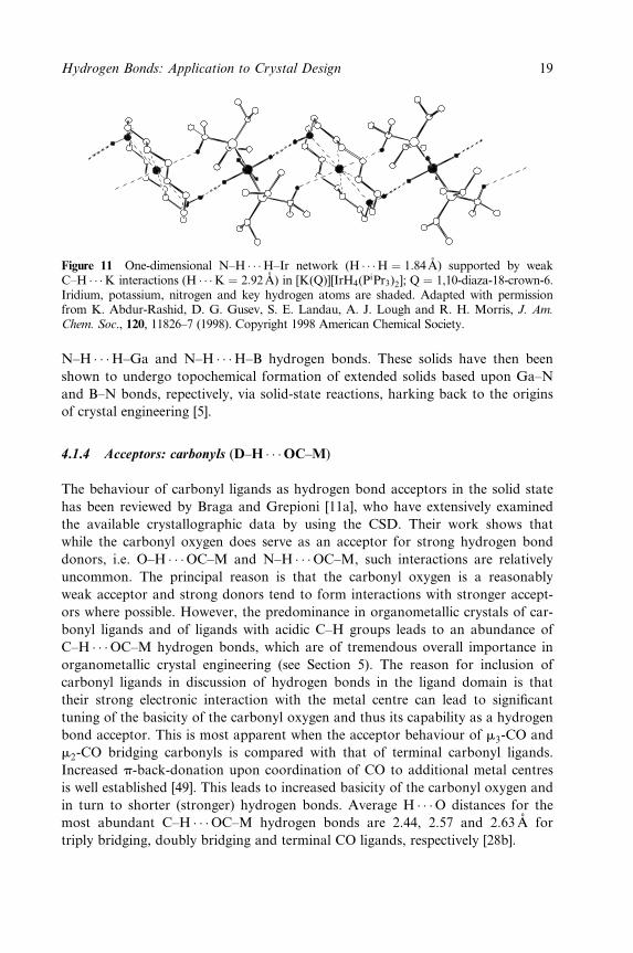
Figure 11 One-dimensional N±H � � �H±Ir network (H � � �H � 1:84 ÊA) supported by weakC±H � � �K interactions (H � � �K � 2:92 ÊA) in [K(Q)][IrH4(P
iPr3)2]; Q � 1,10-diaza-18-crown-6.Iridium, potassium, nitrogen and key hydrogen atoms are shaded. Adapted with permissionfrom K. Abdur-Rashid, D. G. Gusev, S. E. Landau, A. J. Lough and R. H. Morris, J. Am.
Chem. Soc., 120, 11826±7 (1998). Copyright 1998 American Chemical Society.
N±H � � �H±Ga and N±H � � �H±B hydrogen bonds. These solids have then been
shown to undergo topochemical formation of extended solids based upon Ga±N
and B±N bonds, repectively, via solid-state reactions, harking back to the origins
of crystal engineering [5].
4.1.4 Acceptors: carbonyls (D±H � � �OC±M)
The behaviour of carbonyl ligands as hydrogen bond acceptors in the solid state
has been reviewed by Braga and Grepioni [11a], who have extensively examined
the available crystallographic data by using the CSD. Their work shows that
while the carbonyl oxygen does serve as an acceptor for strong hydrogen bond
donors, i.e. O±H � � �OC±M and N±H � � �OC±M, such interactions are relatively
uncommon. The principal reason is that the carbonyl oxygen is a reasonably
weak acceptor and strong donors tend to form interactions with stronger accept-
ors where possible. However, the predominance in organometallic crystals of car-
bonyl ligands and of ligands with acidic C±H groups leads to an abundance of
C±H � � �OC±M hydrogen bonds, which are of tremendous overall importance in
organometallic crystal engineering (see Section 5). The reason for inclusion of
carbonyl ligands in discussion of hydrogen bonds in the ligand domain is that
their strong electronic interaction with the metal centre can lead to signi®cant
tuning of the basicity of the carbonyl oxygen and thus its capability as a hydrogen
bond acceptor. This is most apparent when the acceptor behaviour of m3-CO and
m2-CO bridging carbonyls is compared with that of terminal carbonyl ligands.
Increased p-back-donation upon coordination of CO to additional metal centres
is well established [49]. This leads to increased basicity of the carbonyl oxygen and
in turn to shorter (stronger) hydrogen bonds. Average H � � �O distances for the
most abundant C±H � � �OC±M hydrogen bonds are 2.44, 2.57 and 2.63AÊ for
triply bridging, doubly bridging and terminal CO ligands, respectively [28b].
Hydrogen Bonds: Application to Crystal Design 19
4.2 Periphery Domain: Networks Formed by Direct Ligand±Ligand Hydrogen
Bonds Between Building Blocks
In the Periphery Domain, the role of the metal in hydrogen bonding is less prom-
inent than in the Ligand Domain. However, it can still exert an in¯uence over
directing hydrogen bond formation, in some cases exerting a weak electronic
in¯uence and in others serving more as a constituent of a pendant group in an
organic hydrogen-bonded network.
This area of forming hydrogen-bonded networks using coordination com-
pounds has recently been reviewed by Beatty [11f]. The review was organized
primarily on the basis of the dimensionality of the network formed, i.e. 1D vs 2D
vs 3D. In order to complement that review, the primary organization of this
section instead focuses on the category of ligand used to provide the hydrogen-
bonded links between building blocks.
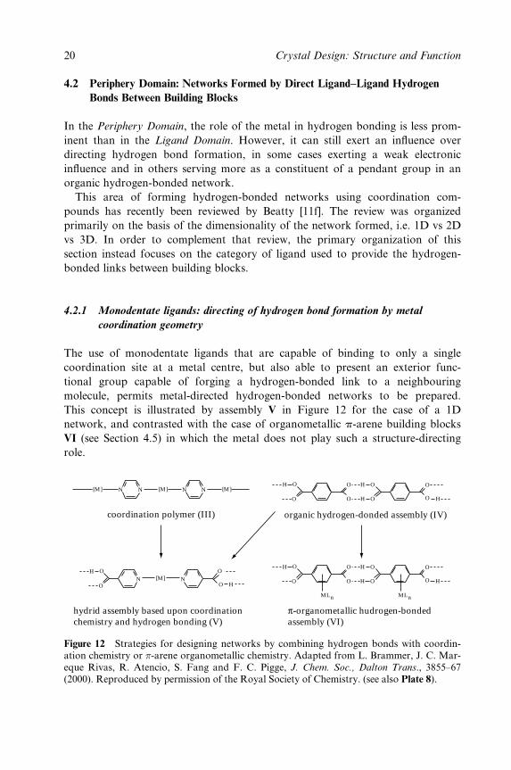
4.2.1 Monodentate ligands: directing of hydrogen bond formation by metal
coordination geometry
The use of monodentate ligands that are capable of binding to only a single
coordination site at a metal centre, but also able to present an exterior func-
tional group capable of forging a hydrogen-bonded link to a neighbouring
molecule, permits metal-directed hydrogen-bonded networks to be prepared.
This concept is illustrated by assembly V in Figure 12 for the case of a 1D
network, and contrasted with the case of organometallic p-arene building blocks
VI (see Section 4.5) in which the metal does not play such a structure-directing
role.
coordination polymer (III)
hydrid assembly based upon coordinationchemistry and hydrogen bonding (V)
π-organometallic hudrogen-bondedassembly (VI)
N NN N[M] [M] [M]O OH
O
O O
O
H
O OH H
N N[M]OH
O O H
O
organic hydrogen-donded assembly (IV)
O OH
O
O O
O
H
O OH H
MLn MLn
Figure 12 Strategies for designing networks by combining hydrogen bonds with coordin-ation chemistry or �-arene organometallic chemistry. Adapted from L. Brammer, J. C. Mar-eque Rivas, R. Atencio, S. Fang and F. C. Pigge, J. Chem. Soc., Dalton Trans., 3855±67(2000). Reproduced by permission of the Royal Society of Chemistry. (see also Plate 8).
20 Crystal Design: Structure and Function

The relationship between the 1D assembly V and either the coordination poly-
mer III or the organic hydrogen-bonded assembly IV is readily apparent. Concep-
tually, the relationships involve replacement of linear N±M±N linkages by linear
hydrogen-bonded linkages (carboxyl dimer) or vice versa. A linear assembly such
as V results not only from the linear hydrogen-bonded link, but from the rigidity
of the ligands and from the trans coordination of the ligands at the metal centre.
Herein lies the metal's structure-directing role, namely orientation of the hydrogen
bonding groups so as to direct the assembly of the building blocks. This contrasts
with the situation suggested by VI in which the parent organic network remains
essentially unchanged, and the metal-containing moiety (MLn) is appended by
coordination of the arene in a p manner. The concept embodied in V is in
principle amenable to a variety of self-recognizing functional groups, such as
carboxylic acids, amides and oximes, and is not limited to coordination of only
two functional ligands at each metal centre (Figure 13).
4.2.1.1 ML2 building blocks
A series of predominantly ID assemblies have been prepared by AakeroÈy and
co-workers using silver(I) ions [50], which have a tendency to adopt a linear two-
coordinate geometry (i.e. AgL�2 building blocks, cf. VII, XVII, XVIII). These
assemblies are obtained with ligands L � pyridine-4-carboxamide (isonicotina-
mide) [50a], pyridine-3-aldoxime [50b] and pyridine-3-acetoxime [50b], when using
MMMMM
MMMMM
VII VIII IX X XI
XVIXVXIVXIIIXII
MM M M M
XXIXXXIXXVIIIXVII
Figure 13 Schematic representation of coordination compounds with rigid monodentateligands bearing hydrogen bonding groups (e.g. substituted pyridines). Arrangements VII±XVIare representative of 4-pyridine ligands and arrangements XVII±XXI of 3-pyridine ligands.
Hydrogen Bonds: Application to Crystal Design 21
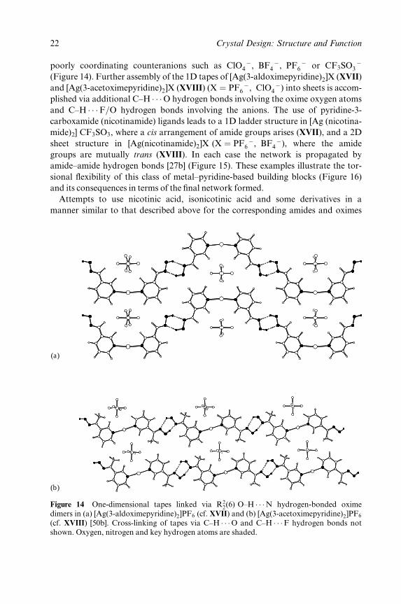
poorly coordinating counteranions such as ClO ÿ4 , BF ÿ
4 , PF ÿ6 or CF3SO ÿ
3
(Figure 14). Further assembly of the 1D tapes of [Ag(3-aldoximepyridine)2]X (XVII)
and [Ag(3-acetoximepyridine)2]X (XVIII) (X � PF ÿ6 , ClO ÿ
4 ) into sheets is accom-
plished via additional C±H � � �O hydrogen bonds involving the oxime oxygen atoms
and C±H � � �F=O hydrogen bonds involving the anions. The use of pyridine-3-
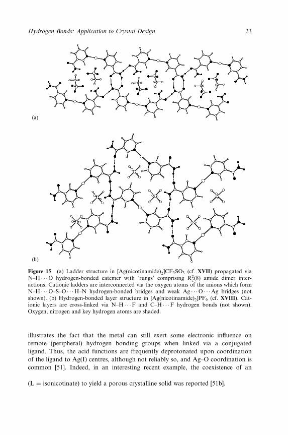
carboxamide (nicotinamide) ligands leads to a 1D ladder structure in [Ag (nicotina-
mide)2] CF3SO3, where a cis arrangement of amide groups arises (XVII), and a 2D
sheet structure in [Ag(nicotinamide)2]X (X � PF ÿ6 , BF ÿ
4 ), where the amide
groups are mutually trans (XVIII). In each case the network is propagated by
amide±amide hydrogen bonds [27b] (Figure 15). These examples illustrate the tor-
sional ¯exibility of this class of metal±pyridine-based building blocks (Figure 16)
and its consequences in terms of the ®nal network formed.
Attempts to use nicotinic acid, isonicotinic acid and some derivatives in a
manner similar to that described above for the corresponding amides and oximes
(a)
(b)
Figure 14 One-dimensional tapes linked via R22(6) O±H � � �N hydrogen-bonded oxime
dimers in (a) [Ag(3-aldoximepyridine)2]PF6 (cf. XVII) and (b) [Ag(3-acetoximepyridine)2]PF6
(cf. XVIII) [50b]. Cross-linking of tapes via C±H � � �O and C±H � � �F hydrogen bonds notshown. Oxygen, nitrogen and key hydrogen atoms are shaded.
22 Crystal Design: Structure and Function
(a)
(b)
Figure 15 (a) Ladder structure in [Ag(nicotinamide)2]CF3SO3 (cf. XVII) propagated viaN±H � � �O hydrogen-bonded catemer with `rungs' comprising R2
2(8) amide dimer inter-actions. Cationic ladders are interconnected via the oxygen atoms of the anions which formN±H � � �O±S±O � � �H±N hydrogen-bonded bridges and weak Ag � � �O � � �Ag bridges (notshown). (b) Hydrogen-bonded layer structure in [Ag(nicotinamide)2]PF6 (cf. XVIII). Cat-ionic layers are cross-linked via N±H � � �F and C±H � � �F hydrogen bonds (not shown).Oxygen, nitrogen and key hydrogen atoms are shaded.
illustrates the fact that the metal can still exert some electronic in¯uence on
remote (peripheral) hydrogen bonding groups when linked via a conjugated
ligand. Thus, the acid functions are frequently deprotonated upon coordination
of the ligand to Ag(I) centres, although not reliably so, and Ag±O coordination is
common [51]. Indeed, in an interesting recent example, the coexistence of an
[Ag(L)] coordination network with an [Ag(L)(HL)] hydrogen-bonded network
(L � isonicotinate) to yield a porous crystalline solid was reported [51b].
Hydrogen Bonds: Application to Crystal Design 23

H
[M]
H
ON
N
H
H
O
N
[M] N
nicotinamide ligandisonicotinamide ligand
α
β
γ δ
Figure 16 Nicotinamide (pyridine-3-carboxamide) and isonicotinamide (pyridine-4-carbox-amide) ligands. Curved arrows indicated torsional ¯exibility at positions a±d. Reprintedfrom L. Brammer, J. C. Mareque Rivas, R. Atencio, S. Fang and F. C. Pigge, J. Chem. Soc.,
Dalton Trans., 3855±67 (2000). Reproduced by permission of the Royal Society of Chemistry.
Gold(I) is also well known for forming linear two-coordinate compounds as it is
for forming attractive Au � � �Au interactions, so-called `aurophilic' interactions, the
strengths of which are comparable to those of many hydrogen bonds. Schmidbaur
and co-workers have harnessed both aurophilic interactions and direct ligand±
ligand hydrogen bonds in preparing examples of 1D and 2D networks using neutral
Au(I) building blocks containing phosphine and thiolate ligands [52].
4.2.1.2 ML3 building blocks
AakeroÈy et al. were also able to prepare building blocks based upon Ag(I) centres
coordinated in a trigonal planar manner by three isonicotinamide ligands. The
isostructural perchlorate and tetra¯uoroborate salts of these cationic complexes
involve amide±amide hydrogen-bonded links from each cation to six others, result-
ing in 3D interpenetrated networks that resemble the network found in a-ThSi [53].
4.2.1.3 Square-planar ML4 building blocks
Networks based upon homoleptic cationic building blocks consisting of square-
planar Pt(II) or Ni(II) centres coordinated by the functionalized pyridine ligands
discussed above have been prepared by the groups of AakeroÈy and Brammer
[27a,b,54]. Steric interactions between ortho hydrogen atoms require the pyridine
rings to lie approximately orthogonal to the metal coordination plane (MN4).
Thus, whereas for 4-substituted pyridines the hydrogen bonding groups are pro-
jected in directions that effectively amplify the metal coordination geometry
(cf. IX), for 3-substituted pyridines the hydrogen bonding groups can be oriented
either above or below the coordination plane (XIX±XXI). In the structures of
[Pt(nicotinamide)4]Cl2 and [Pt(nicotinamide)4](PF6)2 �H2O, the cations adopt a
centrosymmetric arrangement with two amide groups `up' and two `down' (cf.
XIX). Remarkably, the principal feature common to the two structures is the layer
24 Crystal Design: Structure and Function

arrangement of the cations, which is sustained by interdigitation of the ligands
involving by p±p and C±H � � �p interactions. In [Pt(nicotinamide)4]Cl2 [54a,b], all
amide groups are linked to another in the next layer via the well-known R22(8) [55]
hydrogen-bonded dimer supramolecular synthon leading to a 1D zig-zag hydrogen-
bonded tape (Figure 17). This resembles the tape structures observed for
[Ag(3-acetoximepyridine)2]X (X � PF ÿ6 , ClO ÿ
4 ) [49b] and [Ag(L)(HL)] (L� nico-
tinate) [51a], except that for [Pt(nicotinamide)4]Cl2 two links occur between each
metal centre along the chain. An analogous tape structure is also found in
[Cu2(m2-acetonato-O)-2-(6-cyano-3-methylpyridin-2(1H)-one](BF4)2 [56]. In [Pt
(nicotinamide)4](PF6)2 �H2O [54a,c], the spacing between cation layers is in-
creased to accommodate the larger anions and the water molecules. Amide±amide
hydrogen bonds between the layers are no longer possible. However, rotation of
the amide groups (angle b in Figure 16) permits weaker amide±amide hydrogen
bonds within the cation layer.
The use of isonicotinic acid ligands leads to a threefold interpenetrated neutral
square grid network in which [Pt(L)2(HL)2] building blocks (L � isonicotinate)
(cf. IX), resulting from deprotonation of half of the acid groups, are linked by
carboxyl±carboxylate hydrogen bonds (Figure 18) [27c,57]. A network of the same
Figure 17 Hydrogen-bonded tapes comprised of cationic [Pt(nicotinamide)4]2�, with chlor-
ide ions in channels between tapes. (Reprinted from J. C. Mareque Rivas and L. Brammer,New J. Chem., 22, 1315±8 (1998). Reproduced by permission of the Royal Society ofChemistry (RSC) and the Centre National de la Recherche Scienti®que (CNRS).
Hydrogen Bonds: Application to Crystal Design 25

Figure 18 Section of one of the O±H � � �Oÿ hydrogen-bonded square grids found in[Pt(L)2(HL)2] � 2H2O(L � isonicotinate) (cf. IX) [27c]. Water molecules occupy the channelsalong the crystallographic c-axis (not shown). Pt � � �Pt separations are 16.2AÊ . Oxygen,nitrogen and key hydrogen atoms are shaded.
topology (and also threefold interpenetrated) is found in the structure of trans-
[Ni(L)4(OH2)2]Br2 � 2L (L � pyridine-4-aldoxime) [27c]. However, the use of
O±H � � �O hydrogen bonds to link oxime groups of neighbouring building blocks
rather than the expected O±H � � �N bonded R22(6) synthon leads to considerable
distortion of the square grid (Figure 19). As in the previously described examples
that involve amide groups in Section 4.2.1, the use of the square-planar building
block [M(L)4]2� (M � Ni, Pt; L � isonicotinamide) has led to a variety of differ-
ent hydrogen-bonded architectures. trans-[Ni(L)4(OH2)2]ClO4 � 2H2O leads to cat-
ionic layers in which sets of four amide groups from neighbouring units interact
in an R44(16) hydrogen-bonded ring [27c]. [Pt(L)4](PF6)2 [27a] and [Pt(L)4]Cl2 � 4L
[27c] form complicated hydrogen-bonded networks. Both contain one-dimensional
networks propagated via R22(8) synthons between amide groups which trans
ligands interact (cf. XIII). In [Pt(L)4](PF6)2 the remaining two amide groups pro-
vide cross-linking via R44(16) hydrogen-bonded rings involving amide groups from
four different cations. In [Pt(L)4]Cl2 � 4L, two sets of one-dimensional chains in-
volving R22(8) amide±amide synthons run in roughly orthogonal directions and are
linked by an extensive network of hydrogen bonds involving the remaining amide
groups of the coordinated ligands, the isonicotinamide guest molecules and
26 Crystal Design: Structure and Function
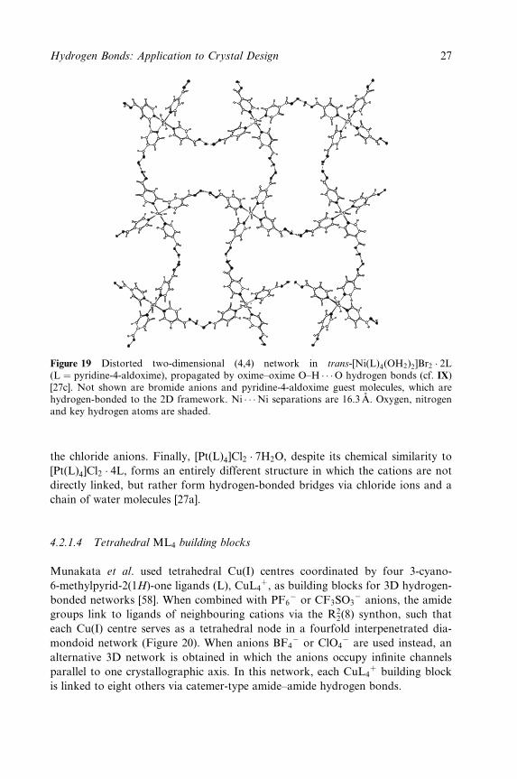
Figure 19 Distorted two-dimensional (4,4) network in trans-[Ni(L)4(OH2)2]Br2 � 2L(L � pyridine-4-aldoxime), propagated by oxime±oxime O±H � � �O hydrogen bonds (cf. IX)[27c]. Not shown are bromide anions and pyridine-4-aldoxime guest molecules, which arehydrogen-bonded to the 2D framework. Ni � � �Ni separations are 16.3 AÊ . Oxygen, nitrogenand key hydrogen atoms are shaded.
the chloride anions. Finally, [Pt(L)4]Cl2 � 7H2O, despite its chemical similarity to
[Pt(L)4]Cl2 � 4L, forms an entirely different structure in which the cations are not
directly linked, but rather form hydrogen-bonded bridges via chloride ions and a
chain of water molecules [27a].
4.2.1.4 Tetrahedral ML4 building blocks
Munakata et al. used tetrahedral Cu(I) centres coordinated by four 3-cyano-
6-methylpyrid-2(1H)-one ligands (L), CuL4�, as building blocks for 3D hydrogen-
bonded networks [58]. When combined with PF6ÿ or CF3SO3
ÿ anions, the amide
groups link to ligands of neighbouring cations via the R22(8) synthon, such that
each Cu(I) centre serves as a tetrahedral node in a fourfold interpenetrated dia-
mondoid network (Figure 20). When anions BF4ÿ or ClO4
ÿ are used instead, an
alternative 3D network is obtained in which the anions occupy in®nite channels
parallel to one crystallographic axis. In this network, each CuL4� building block
is linked to eight others via catemer-type amide±amide hydrogen bonds.
Hydrogen Bonds: Application to Crystal Design 27
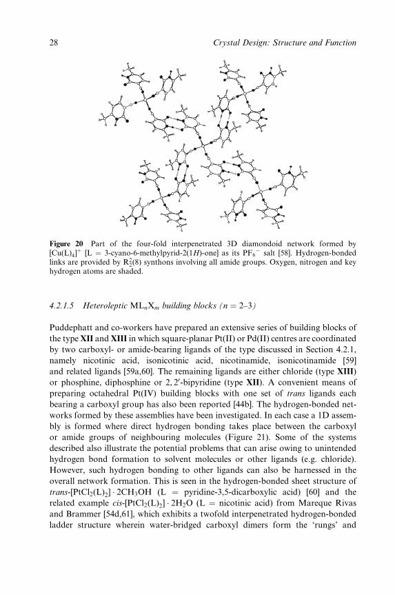
Figure 20 Part of the four-fold interpenetrated 3D diamondoid network formed by[Cu(L)4]
� [L � 3-cyano-6-methylpyrid-2(1H)-one] as its PF6ÿ salt [58]. Hydrogen-bonded
links are provided by R22(8) synthons involving all amide groups. Oxygen, nitrogen and key
hydrogen atoms are shaded.
4.2.1.5 Heteroleptic MLnXm building blocks (n � 2±3)
Puddephatt and co-workers have prepared an extensive series of building blocks of
the type XII and XIII in which square-planar Pt(II) or Pd(II) centres are coordinated
by two carboxyl- or amide-bearing ligands of the type discussed in Section 4.2.1,
namely nicotinic acid, isonicotinic acid, nicotinamide, isonicotinamide [59]
and related ligands [59a,60]. The remaining ligands are either chloride (type XIII)
or phosphine, diphosphine or 2, 20-bipyridine (type XII). A convenient means of
preparing octahedral Pt(IV) building blocks with one set of trans ligands each
bearing a carboxyl group has also been reported [44b]. The hydrogen-bonded net-
works formed by these assemblies have been investigated. In each case a 1D assem-
bly is formed where direct hydrogen bonding takes place between the carboxyl
or amide groups of neighbouring molecules (Figure 21). Some of the systems
described also illustrate the potential problems that can arise owing to unintended
hydrogen bond formation to solvent molecules or other ligands (e.g. chloride).
However, such hydrogen bonding to other ligands can also be harnessed in the
overall network formation. This is seen in the hydrogen-bonded sheet structure of
trans-[PtCl2(L)2] � 2CH3OH (L � pyridine-3,5-dicarboxylic acid) [60] and the
related example cis-[PtCl2(L)2] � 2H2O (L � nicotinic acid) from Mareque Rivas
and Brammer [54d,61], which exhibits a twofold interpenetrated hydrogen-bonded
ladder structure wherein water-bridged carboxyl dimers form the `rungs' and
28 Crystal Design: Structure and Function
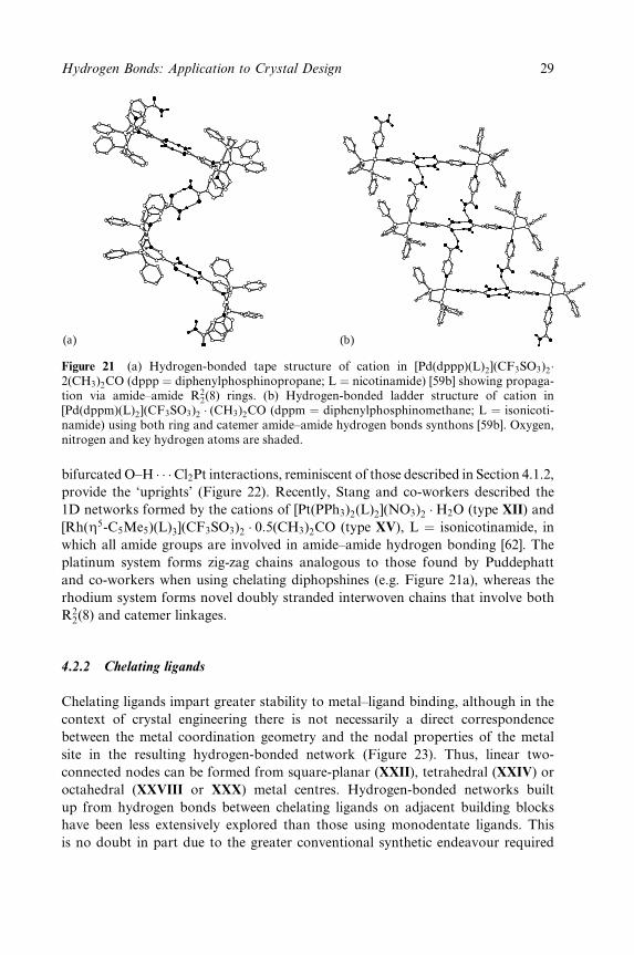
(a) (b)
Figure 21 (a) Hydrogen-bonded tape structure of cation in [Pd(dppp)(L)2](CF3SO3)2�2(CH3)2CO (dppp � diphenylphosphinopropane; L � nicotinamide) [59b] showing propaga-tion via amide±amide R2
2(8) rings. (b) Hydrogen-bonded ladder structure of cation in[Pd(dppm)(L)2](CF3SO3)2 � (CH3)2CO (dppm � diphenylphosphinomethane; L � isonicoti-namide) using both ring and catemer amide±amide hydrogen bonds synthons [59b]. Oxygen,nitrogen and key hydrogen atoms are shaded.
bifurcated O±H � � �Cl2Pt interactions, reminiscent of those described in Section 4.1.2,
provide the `uprights' (Figure 22). Recently, Stang and co-workers described the
1D networks formed by the cations of [Pt(PPh3)2(L)2](NO3)2 �H2O (type XII) and
[Rh(Z5-C5Me5)(L)3](CF3SO3)2 � 0:5(CH3)2CO (type XV), L � isonicotinamide, in
which all amide groups are involved in amide±amide hydrogen bonding [62]. The
platinum system forms zig-zag chains analogous to those found by Puddephatt
and co-workers when using chelating diphopshines (e.g. Figure 21a), whereas the
rhodium system forms novel doubly stranded interwoven chains that involve both
R22(8) and catemer linkages.
4.2.2 Chelating ligands
Chelating ligands impart greater stability to metal±ligand binding, although in the
context of crystal engineering there is not necessarily a direct correspondence
between the metal coordination geometry and the nodal properties of the metal
site in the resulting hydrogen-bonded network (Figure 23). Thus, linear two-
connected nodes can be formed from square-planar (XXII), tetrahedral (XXIV) or
octahedral (XXVIII or XXX) metal centres. Hydrogen-bonded networks built
up from hydrogen bonds between chelating ligands on adjacent building blocks
have been less extensively explored than those using monodentate ligands. This
is no doubt in part due to the greater conventional synthetic endeavour required
Hydrogen Bonds: Application to Crystal Design 29
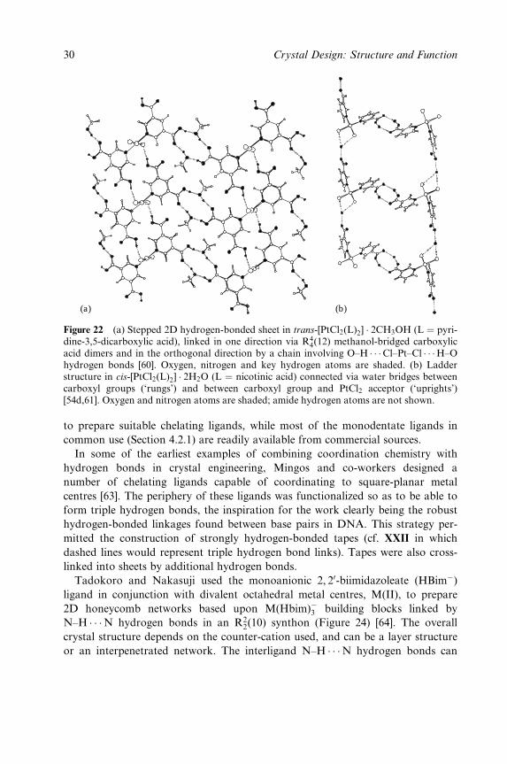
(a) (b)
Figure 22 (a) Stepped 2D hydrogen-bonded sheet in trans-[PtCl2(L)2] � 2CH3OH (L � pyri-dine-3,5-dicarboxylic acid), linked in one direction via R4
4(12) methanol-bridged carboxylicacid dimers and in the orthogonal direction by a chain involving O±H � � �Cl±Pt±Cl � � �H±Ohydrogen bonds [60]. Oxygen, nitrogen and key hydrogen atoms are shaded. (b) Ladderstructure in cis-[PtCl2(L)2] � 2H2O (L � nicotinic acid) connected via water bridges betweencarboxyl groups (`rungs') and between carboxyl group and PtCl2 acceptor (`uprights')[54d,61]. Oxygen and nitrogen atoms are shaded; amide hydrogen atoms are not shown.
to prepare suitable chelating ligands, while most of the monodentate ligands in
common use (Section 4.2.1) are readily available from commercial sources.
In some of the earliest examples of combining coordination chemistry with
hydrogen bonds in crystal engineering, Mingos and co-workers designed a
number of chelating ligands capable of coordinating to square-planar metal
centres [63]. The periphery of these ligands was functionalized so as to be able to
form triple hydrogen bonds, the inspiration for the work clearly being the robust
hydrogen-bonded linkages found between base pairs in DNA. This strategy per-
mitted the construction of strongly hydrogen-bonded tapes (cf. XXII in which
dashed lines would represent triple hydrogen bond links). Tapes were also cross-
linked into sheets by additional hydrogen bonds.
Tadokoro and Nakasuji used the monoanionic 2, 20-biimidazoleate (HBimÿ)
ligand in conjunction with divalent octahedral metal centres, M(II), to prepare
2D honeycomb networks based upon M(Hbim)ÿ3 building blocks linked by
N±H � � �N hydrogen bonds in an R22(10) synthon (Figure 24) [64]. The overall
crystal structure depends on the counter-cation used, and can be a layer structure
or an interpenetrated network. The interligand N±H � � �N hydrogen bonds can
30 Crystal Design: Structure and Function
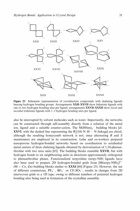
L
L
M
MM M
M
M
M M M
XXII XXIII XXIV XXV
XXVI XXVIIXXVIII
XXIX
XXX XXXI XXXII
Figure 23 Schematic representation of coordination compounds with chelating ligandsbearing hydrogen bonding groups. Arrangements XXII±XXVII show bidentate ligands withone or two hydrogen bonding sites per ligand; arrangements XXVII±XXXII show facial andmeridial tridentate ligands with 1±3 hydrogen bonding sites per ligand.
also be interrupted by solvent molecules such as water. Importantly, the networks
can be constructed through self-assembly directly from a solution of the metal
ion, ligand and a suitable counter-cation. The M(Hbim)3ÿ building blocks [cf.
XXVI, with the dashed line representing the R22(10) N±H � � �N linkage] are chiral,
although the resulting honeycomb network is not, since alternating R and S
enantiomers are employed in its construction. Lehn and co-workers prepared
nanoporous hydrogen-bonded networks based on coordination to octahedral
metal centres of three chelating ligands obtained by derivatization of 1,10-phenan-
throline with two urea units [65]. The building blocks resemble XXVII, but with
hydrogen bonds to six neighbouring units in directions approximately orthogonal
to phenanthroline planes. Functionalized terpyridine (terpy-NH) ligands have
also been used to prepare 2D hydrogen-bonded grids from [M(terpy-NH)2]2�
(M � Co, Zn) building blocks similar to XXXI [66] (Figure 25). However, the use
of different counterions, PF6ÿ, BF4
ÿ or CF3SO3ÿ, results in changes from 2D
interwoven grids to a 1D tape, owing to different numbers of potential hydrogen
bonding sites being used in formation of the crystalline assembly.
Hydrogen Bonds: Application to Crystal Design 31
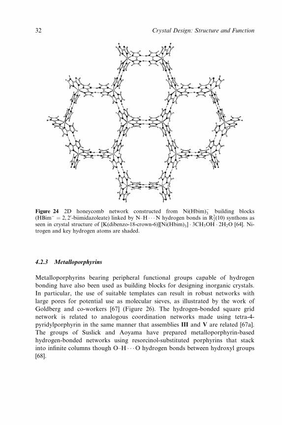
Figure 24 2D honeycomb network constructed from Ni(Hbim)ÿ3 building blocks(HBimÿ � 2, 20-biimidazoleate) linked by N±H � � �N hydrogen bonds in R2
2(10) synthons asseen in crystal structure of [K(dibenzo-18-crown-6)][Ni(Hbim)3] � 3CH3OH � 2H2O [64]. Ni-trogen and key hydrogen atoms are shaded.
4.2.3 Metalloporphyrins
Metalloporphyrins bearing peripheral functional groups capable of hydrogen
bonding have also been used as building blocks for designing inorganic crystals.
In particular, the use of suitable templates can result in robust networks with
large pores for potential use as molecular sieves, as illustrated by the work of
Goldberg and co-workers [67] (Figure 26). The hydrogen-bonded square grid
network is related to analogous coordination networks made using tetra-4-
pyridylporphyrin in the same manner that assemblies III and V are related [67a].
The groups of Suslick and Aoyama have prepared metalloporphyrin-based
hydrogen-bonded networks using resorcinol-substituted porphyrins that stack
into in®nite columns though O±H � � �O hydrogen bonds between hydroxyl groups
[68].
32 Crystal Design: Structure and Function
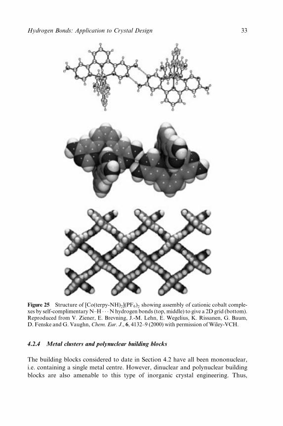
Figure 25 Structure of [Co(terpy-NH)2](PF6)2 showing assembly of cationic cobalt comple-xes by self-complimentary N±H � � �N hydrogen bonds (top, middle) to give a 2D grid (bottom).Reproduced from V. Ziener, E. Brevning, J.-M. Lehn, E. Wegelius, K. Rissanen, G. Baum,D. Fenske and G. Vaughn, Chem. Eur. J., 6, 4132±9 (2000) with permission of Wiley-VCH.
4.2.4 Metal clusters and polynuclear building blocks
The building blocks considered to date in Section 4.2 have all been mononuclear,
i.e. containing a single metal centre. However, dinuclear and polynuclear building
blocks are also amenable to this type of inorganic crystal engineering. Thus,
Hydrogen Bonds: Application to Crystal Design 33
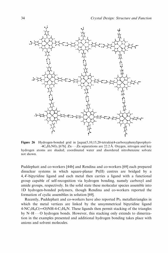
Figure 26 Hydrogen-bonded grid in [aqua(5,10,15,20-tetrakis(4-carboxyphenyl)porphyri-nato)zinc (II)]�4C6H5NO2 [67b]. Zn � � �Zn separations are 22.2 AÊ . Oxygen, nitrogen and keyhydrogen atoms are shaded; coordinated water and disordered nitrobenzene solvatenot shown.
Puddephatt and co-workers [44b] and Rendina and co-workers [69] each prepared
dinuclear systems in which square-planar Pt(II) centres are bridged by a
4, 40-bipyridine ligand and each metal then carries a ligand with a functional
group capable of self-recognition via hydrogen bonding, namely carboxyl and
amide groups, respectively. In the solid state these molecular species assemble into
1D hydrogen-bonded polymers, though Rendina and co-workers reported the
formation of cyclic assemblies in solution [69].
Recently, Puddephatt and co-workers have also reported Pt3 metallatriangles in
which the metal vertices are linked by the unsymmetrical bipyridine ligand
4-NC5H4C(wwO)NH-4-C5H4N. These ligands then permit stacking of the triangles
by N±H � � �O hydrogen bonds. However, this stacking only extends to dimeriza-
tion in the examples presented and additional hydrogen bonding takes place with
anions and solvent molecules.
34 Crystal Design: Structure and Function
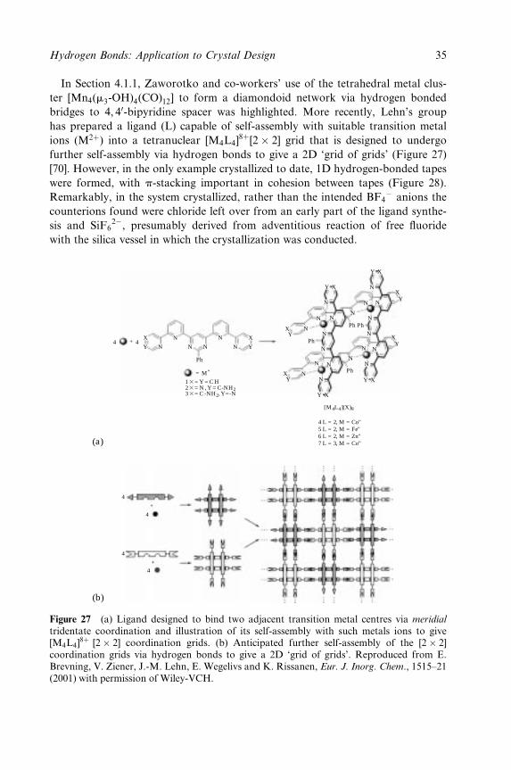
In Section 4.1.1, Zaworotko and co-workers' use of the tetrahedral metal clus-
ter [Mn4(m3-OH)4(CO)12] to form a diamondoid network via hydrogen bonded
bridges to 4, 40-bipyridine spacer was highlighted. More recently, Lehn's group
has prepared a ligand (L) capable of self-assembly with suitable transition metal
ions (M2�) into a tetranuclear [M4L4]8�[2� 2] grid that is designed to undergo
further self-assembly via hydrogen bonds to give a 2D `grid of grids' (Figure 27)
[70]. However, in the only example crystallized to date, 1D hydrogen-bonded tapes
were formed, with p-stacking important in cohesion between tapes (Figure 28).
Remarkably, in the system crystallized, rather than the intended BF4ÿ anions the
counterions found were chloride left over from an early part of the ligand synthe-
sis and SiF62ÿ, presumably derived from adventitious reaction of free ¯uoride
with the silica vessel in which the crystallization was conducted.
(a)
(b)
4 4
4
4
4
+
4+
N
N
N
Ph
= M"
13= Y = C H23= N , Y = C-NH233= C -NH2, Y=-N
[M4L4](X)8
4 L = 2, M = Co"5 L = 2, M = Fe"6 L = 2, M = Zn"7 L = 3, M = Co"
N
N
N
X
Y
X
Y
XY
N
N
N
N
XY
N
N
N
XY
X
X
Y
Y
XY
XY
XY
N
N
NN
N
N
N
N
N
N
N N
N
Ph Ph
Ph
Ph
+
Figure 27 (a) Ligand designed to bind two adjacent transition metal centres via meridial
tridentate coordination and illustration of its self-assembly with such metals ions to give[M4L4]
8� [2� 2] coordination grids. (b) Anticipated further self-assembly of the [2� 2]coordination grids via hydrogen bonds to give a 2D `grid of grids'. Reproduced from E.Brevning, V. Ziener, J.-M. Lehn, E. Wegelivs and K. Rissanen, Eur. J. Inorg. Chem., 1515±21(2001) with permission of Wiley-VCH.
Hydrogen Bonds: Application to Crystal Design 35
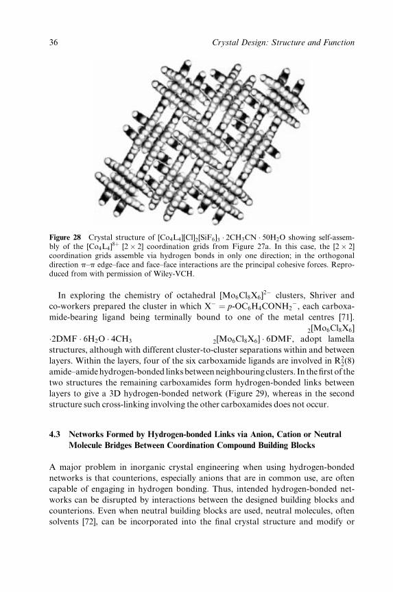
Figure 28 Crystal structure of [Co4L4][Cl]2[SiF6]3 � 2CH3CN � 50H2O showing self-assem-bly of the [Co4L4]
8� [2� 2] coordination grids from Figure 27a. In this case, the [2� 2]coordination grids assemble via hydrogen bonds in only one direction; in the orthogonaldirection p±p edge±face and face±face interactions are the principal cohesive forces. Repro-duced from with permission of Wiley-VCH.
In exploring the chemistry of octahedral [Mo6Cl8X6]2ÿ clusters, Shriver and
co-workers prepared the cluster in which Xÿ � p-OC6H4CONH2ÿ, each carboxa-
mide-bearing ligand being terminally bound to one of the metal centres [71].
The two crystal structures reported as different solvates, [(crypt)Na]2[Mo6Cl8X6]
�2DMF � 6H2O � 4CH3OH and [(crypt)Na]2[Mo6Cl8X6] � 6DMF, adopt lamella
structures, although with different cluster-to-cluster separations within and between
layers. Within the layers, four of the six carboxamide ligands are involved in R22(8)
amide±amidehydrogen-bonded linksbetweenneighbouringclusters. In the®rstof the
two structures the remaining carboxamides form hydrogen-bonded links between
layers to give a 3D hydrogen-bonded network (Figure 29), whereas in the second
structure such cross-linking involving the other carboxamides does not occur.
4.3 Networks Formed by Hydrogen-bonded Links via Anion, Cation or Neutral
Molecule Bridges Between Coordination Compound Building Blocks
A major problem in inorganic crystal engineering when using hydrogen-bonded
networks is that counterions, especially anions that are in common use, are often
capable of engaging in hydrogen bonding. Thus, intended hydrogen-bonded net-
works can be disrupted by interactions between the designed building blocks and
counterions. Even when neutral building blocks are used, neutral molecules, often
solvents [72], can be incorporated into the ®nal crystal structure and modify or
36 Crystal Design: Structure and Function
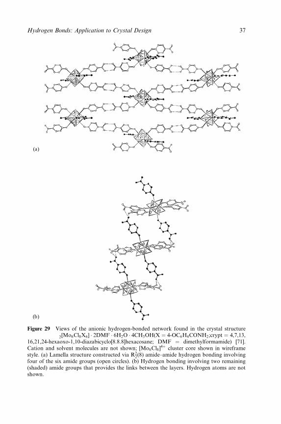
(a)
(b)
Figure 29 Views of the anionic hydrogen-bonded network found in the crystal structureof [(crypt)Na]2[Mo6Cl8X6] � 2DMF � 6H2O � 4CH3OH(X � 4-OC6H4CONH2;crypt � 4,7,13,16,21,24-hexaoxo-1,10-diazabicyclo[8.8.8]hexacosane; DMF � dimethylformamide) [71].Cation and solvent molecules are not shown; [Mo6Cl8]
4� cluster core shown in wireframestyle. (a) Lamella structure constructed via R2
2(8) amide±amide hydrogen bonding involvingfour of the six amide groups (open circles). (b) Hydrogen bonding involving two remaining(shaded) amide groups that provides the links between the layers. Hydrogen atoms are notshown.
Hydrogen Bonds: Application to Crystal Design 37
disrupt the intended hydrogen-bonded network. This section deals not with such
cases, but rather cases in which a counterion or neutral molecule guest has been
used effectively, or at least intentionally, to provide a hydrogen-bonded link
between the functional groups on the periphery of the building blocks.
4.3.1 Anionic bridges
Since the most common combination in coordination chemistry, that of metal
cation and neutral ligands, gives rise to cationic coordination complexes, it is no
surprise that the choice of anion should be of utmost important in designing
hydrogen-bonded networks based upon coordination compounds as building
blocks. This can be seen in Section 4.2, where anions were often selected to
minimize the chance of their forming (accepting) hydrogen bonds and thus maxi-
mize the chance of direct hydrogen bonding between the cationic building blocks.
However, a few groups have adopted a different approach by selecting anions that
can be incorporated deliberately into the hydrogen-bonded network, forming a
bridge between the metal-containing building blocks. Burrows and co-workers
employed metal complexes containing two N,S-chelating thiosemicarbazide
ligands that serve as multiple hydrogen bond donors. When combined with dicar-
boxylate anions such as trans-fumarate or terephthalate, each thiosemicarbazide
ligand forms a double hydrogen bond with one carboxylate group of an anion.
The anion thus forms a bridge between the cationic hydrogen bond donor build-
ing blocks (Figure 30) [73]. Hubberstey and co-workers [74] designed a family of
tetradentate C2ÿ or C3
ÿ linked bis(amidino-O-alkylurea) ligands which provide
eight peripheral N±H hydrogen bond donor sites. These have been linked into
hydrogen-bonded tape structures using four of the eight donor sites to `recognize'
a variety of anions in a common manner (Figure 31). Further hydrogen bonds
involving the other donor sites, and anion as well as solvent water acceptors, lead
to overall hydrogen-bonded aggregation in two dimensions. Jones and co-workers
have reported a number of aminogold(I) compounds in which hydrogen bonding
and aurophilic Au(I) � � �Au(I) interactions are important in the solid state [75].
A particularly compelling example is the structure of bis(pyrrolidine)gold(I) chlor-
ide as its dichloromethane solvate (1:33CH2Cl2). The Au(NC4H5)2� cations form
hydrogen-bonded chains via Clÿ anion bridges. The chains, arranged in parallel
fashion form layers, each layer with its chain direction rotated 90 8 with respect to
neighbouring ones. Au � � �Au interactions then provide a direct link between
cations in adjacent layers leading to a three-dimensional network [75a]. An
interesting system has also been reported by Chen et al. in which trans-
[Ni(OH2)(SCN)4]2ÿ metallate anions are linked via nitrate anions and 4, 40-bipyr-
idinium cations to give a (6,3)-type honeycomb network sustained entirely by
hydrogen bonds [R1210(64) rings] [30e] (Figure 32). Nitrate anions serve as the three
connected nodes by accepting three hydrogen bonds. Each six-node ring
38 Crystal Design: Structure and Function
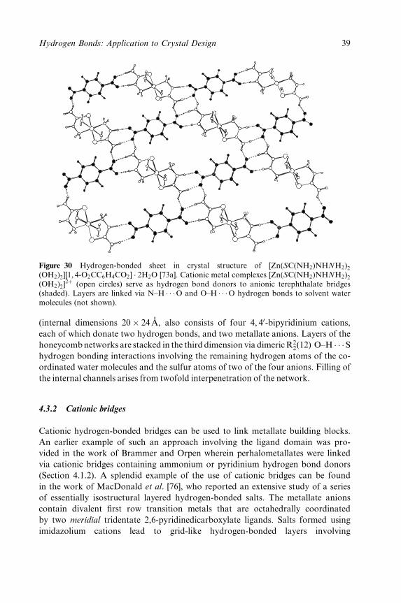
Figure 30 Hydrogen-bonded sheet in crystal structure of [Zn(SC(NH2)NHNH2)2(OH2)2][1, 4-O2CC6H4CO2] � 2H2O [73a]. Cationic metal complexes [Zn(SC(NH2)NHNH2)2(OH2)2]
2� (open circles) serve as hydrogen bond donors to anionic terephthalate bridges(shaded). Layers are linked via N±H � � �O and O±H � � �O hydrogen bonds to solvent watermolecules (not shown).
(internal dimensions 20� 24 ÊA, also consists of four 4, 40-bipyridinium cations,
each of which donate two hydrogen bonds, and two metallate anions. Layers of the
honeycombnetworks are stacked in the third dimension via dimericR22(12) O±H � � � S
hydrogen bonding interactions involving the remaining hydrogen atoms of the co-
ordinated water molecules and the sulfur atoms of two of the four anions. Filling of
the internal channels arises from twofold interpenetration of the network.
4.3.2 Cationic bridges
Cationic hydrogen-bonded bridges can be used to link metallate building blocks.
An earlier example of such an approach involving the ligand domain was pro-
vided in the work of Brammer and Orpen wherein perhalometallates were linked
via cationic bridges containing ammonium or pyridinium hydrogen bond donors
(Section 4.1.2). A splendid example of the use of cationic bridges can be found
in the work of MacDonald et al. [76], who reported an extensive study of a series
of essentially isostructural layered hydrogen-bonded salts. The metallate anions
contain divalent ®rst row transition metals that are octahedrally coordinated
by two meridial tridentate 2,6-pyridinedicarboxylate ligands. Salts formed using
imidazolium cations lead to grid-like hydrogen-bonded layers involving
Hydrogen Bonds: Application to Crystal Design 39
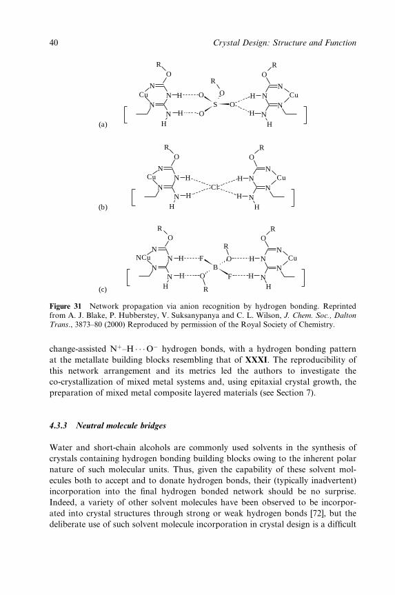
ClN
N
NCu H
NH
H
NN
NCuH
NH
H
OR
OR
OR
OR
SO
OO
O
R
HN
H CuN
NN
H
HN
HCuN
NN
H
(a)
(b)
(c)
F
FOB
O H
H
NN
HCuN NN
H
NN
Cu
NN
H
H
R
R
OR
OR
Figure 31 Network propagation via anion recognition by hydrogen bonding. Reprintedfrom A. J. Blake, P. Hubberstey, V. Suksanypanya and C. L. Wilson, J. Chem. Soc., Dalton
Trans., 3873±80 (2000) Reproduced by permission of the Royal Society of Chemistry.
change-assisted N�±H � � �Oÿ hydrogen bonds, with a hydrogen bonding pattern
at the metallate building blocks resembling that of XXXI. The reproducibility of
this network arrangement and its metrics led the authors to investigate the
co-crystallization of mixed metal systems and, using epitaxial crystal growth, the
preparation of mixed metal composite layered materials (see Section 7).
4.3.3 Neutral molecule bridges
Water and short-chain alcohols are commonly used solvents in the synthesis of
crystals containing hydrogen bonding building blocks owing to the inherent polar
nature of such molecular units. Thus, given the capability of these solvent mol-
ecules both to accept and to donate hydrogen bonds, their (typically inadvertent)
incorporation into the ®nal hydrogen bonded network should be no surprise.
Indeed, a variety of other solvent molecules have been observed to be incorpor-
ated into crystal structures through strong or weak hydrogen bonds [72], but the
deliberate use of such solvent molecule incorporation in crystal design is a dif®cult
40 Crystal Design: Structure and Function
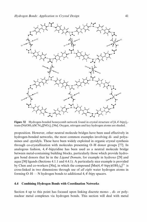
Figure 32 Hydrogen-bonded honeycomb network found in crystal structure of [4, 40-bipy]2-trans-[Ni(OH2)(SCN)4][NO3]2 [30e]. Oxygen, nitrogen and key hydrogen atoms are shaded.
proposition. However, other neutral molecule bridges have been used effectively in
hydrogen-bonded networks, the most common examples involving di- and polya-
mines and -pyridyls. These have been widely exploited in organic crystal synthesis
through co-crystallization with molecules presenting O±H donor groups [77]. In
analogous fashion, 4, 40-bipyridine has been used as a neutral molecule bridge
between metal-containing building blocks, particularly those which provide hydro-
gen bond donors that lie in the Ligand Domain, for example in hydroxo [29] and
aqua [30] ligands (Sections 4.1.1 and 4.4.1). A particularly nice example is provided
by Chen and co-workers [30a], in which the compound [Mn(4, 40-bipy)(OH2)4]2� is
cross-linked in two dimensions through use of all eight water hydrogen atoms in
forming O±H � � �N hydrogen bonds to additional 4, 40-bipy spacers.
4.4 Combining Hydrogen Bonds with Coordination Networks
Section 4 up to this point has focused upon linking discrete mono- , di- or poly-
nuclear metal complexes via hydrogen bonds. This section will deal with metal
Hydrogen Bonds: Application to Crystal Design 41

centres that are already linked into 1D or 2D networks by coordination bonds,
and consider their further cross-linking by hydrogen bonds resulting in networks
of higher dimensionality.
4.4.1 1D coordination polymers with hydrogen-bonded cross-links
There are a number of examples of 1D coordination polymers propagated by
4, 40-bipyridyl (4, 40-bipy) links in which further cross-linking has been accomplished
by M(OH2) � � � (4, 40-bipy) � � � (H2O)M hydrogen-bonded links. Such systems typic-
ally use octahedrally coordinated metal centres, in which trans coordination of
4, 40-bipy leads to the 1D coordination polymer. The additional coordination sites
are then occupied by either two or four water molecules providing O±H donor sites
suitably positioned to form hydrogen-bonded links to additional 4, 40-bipy mol-
ecules in directions orthogonal to the polymer backbone. Such systems are exempli-
®ed by the systems [M(NCE)2(OH2)2(4, 40-bipy)] � (4, 40-bipy) (M � Co, E � S [30c];
M � Fe, E � S or Se [78]). Ciani and co-workers have also explored this theme,
illustrating that both single and double M(OH2) � � � (4, 40-bipy) � � � (H2O)M
hydrogen-bonded links between metal centres can be achieved in related systems
[30d]. In one system, [Fe(OH2)3(ClO4)(4, 40-bipy)]ClO4 � 4, 40-bipy, alternate parallel
{Fe(4, 40-bipy)}n2n� coordination polymers are linked by single then double
hydrogen-bonded 4, 40-bipy bridges.
Direct hydrogen bonding between the ligands of metals contained within adjacent
coordination polymers appears to be less common. The coordination polymer
{[Cd(m-3, 30-pytz)(NO3)2(MeOH)2]}n [3,30-pytz � 3,6-bis(pyrid-3-yl)-1,2,4,5-tetra-
zine] exhibits interchain O±H � � �O hydrogen bonding between the coordinated
methanol and nitrato ligands [31c]. In recent reports, the groups of AakeroÈy [79]
and Nishikiori [80] have cross-linked neutral coordination polymers formed via
small bridging anionic ligands by using pyridine-based ligands (L) that carry
functional groups (carboxyl, amide or oxime) capable of self-recognition through
hydrogen bonds. These result in 2D sheet structures. The copper(I) halide coord-
ination polymers [Cu(m3-X)L]n (X � Cl, I) have a repeat distance along the poly-
mer backbone of ca 3.7±4.1AÊ that is suitable for p±p stacking between pyridine
rings (Figure 33). The Ni(II) thiocyanate coordination polymers, [Ni(m-SCN)2L2],
by virtue of the longer bridging anions, give rise to a larger spacing (ca 5.5 AÊ )
between the metal sites to which the pyridine-based hydrogen bond linkers are
coordinated. This spacing is small enough to prevent interpenetration of the
resulting 2D network, but permits inclusion of large aromatic guest molecules by
expansion and compression of alternate cavities due to the ¯exibility of the hydro-
gen-bonded linkage (Figure 34). The authors also noted that isostructural
host can be prepared using Cu(II) or Cd(II) in place of Ni(II). Zubieta and
co-workers used a similar approach to link oxomolybdate polymers using 4-pyridyl-
40-pyridiniumamine (Hbpa) ligands that are coordinated to Mo sites on one
42 Crystal Design: Structure and Function

(a)
(b)
Figure 33 (a) Cross-linking of {Cu(L)I}n coordination polymer via amide±amide hydrogenbonds between isonicotinamide ligands (L) to give a sheet structure [79a]. (b) Linking of 2Dsheets in third dimensions via short N±H � � � I(Cu) hydrogen bonds (H � � � I � 2:75 ÊA).Oxygen, nitrogen and key hydrogen atoms are shaded; copper iodide polymer shown inwireframe style.
chain and form bifurcated N±H � � �O2Mo hydrogen bonds to a neighbouring
chain, leading to 2D sheets of composition [Mo4O13(Hbpa)2] [81]. Orpen and
co-workers reported the formation of [{MCl4}n]2nÿ chains (M � Mn, Cd) sup-
ported by hydrogen-bonded cross-linking of H2(4, 40-bipy) cations that form bi-
furcated N±H � � �Cl2M hydrogen bonds [82].
Recently, Prior and Rosseinsky [83] prepared by hydrothermal means a coord-
ination polymer [Ni(m-1, 4-H2NC6H4NH2)(H2TMA)(OH2)2]n [H3TMA � ben-
zene-1,3,5-tricarboxylic acid (trimesic acid)], which has an all-trans geometry at
the nickel centres. The carboxyl functional groups and the water molecules engage
in extensive hydrogen bonding leading to in®nite hydrogen-bonded sheets that lie
approximately orthogonal to the direction of propagation of the coordination
polymer. A 3D network, {(NH4)[Yb(DMF)4][Pt(CN)4]2}n (DMF � dimethylfor-
mamide), in which coordination bonds give rise to propagation in one direction
while hydrogen bonds provide links in the other two has also been reported by
Shore and co-workers [84]. The system consists of in®nite square columns of com-
position {[Yb(DMF)4][Pt(CN)4]2}nnÿ in which Yb(DMF)4 and two [Pt(CN)4]
2ÿ
moieties provide the corners of the Yb2Pt2 squares that are then linked into
columns by further bridging [Pt(CN)4]2ÿ units. These 1D `coordination
Hydrogen Bonds: Application to Crystal Design 43

Figure 34 Cross-linking of {Ni(m-SCN)2L2}n coordination polymer via carboxyl±carboxylhydrogen bonds between isonicotinic acid ligands (L) to give a sheet structure which stacksproviding channels that can accommodate polycyclic aromatic hydrocarbon guest mol-ecules, here anthracene [80]. Oxygen, nitrogen and key hydrogen atoms are shaded; nickelthiocyanate polymer and anthracene guest molecules shown in wireframe style.
columns' are then linked in the other two directions by N±H � � �NC(Pt) hydrogen
bonds from the ammonium cations, in which all ammonium hydrogens and all
terminal cyano ligands participate.
4.4.2 2D coordination networks with hydrogen-bonded cross-links
There are many examples of two-dimensional coordination networks involving
organic bridging ligands, often using pyridyl groups [8c,g]. However, examples of
such networks, which are also cross-linked in the third dimension by hydrogen
bonds, are surprisingly rare. A particularly nice example is provided by Lauher
and co-workers [85]. Pyridyl-derivatized urea and oxalamide ligands when com-
bined with silver(I) salts lead to coordination networks in which each metal ion
serves as a four-connected node, with its local geometry being that of a ¯attened
tetrahedron. The resulting 2D grid coordination network is linked in the third
dimension by a well-established pattern of hydrogen bonds between the urea or
oxalamide functionalities.
44 Crystal Design: Structure and Function
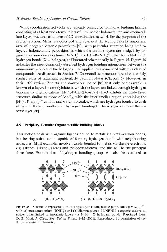
While coordination networks are typically considered to involve bridging ligands
consisting of at least two atoms, it is useful to include halometallate and oxometal-
late layer structures as a form of 2D coordination network for the purposes of the
present section. Mitzi has described and reviewed the technologically important
area of inorganic±organic perovskites [43], with particular attention being paid to
layered halometallate perovskites in which the anionic layers are bridged by or-
ganic alkylammonium cations, R±NH�3 or (H3N±R±NH3)2�, that form N±H � � �X
hydrogen bonds (X � halogen), as illustrated schematically in Figure 35. Figure 36
indicates the most commonly observed hydrogen bonding interactions between the
ammonium group and the halogens. The applications associated with this class of
compounds are discussed in Section 7. Oxometallate structures are also a widely
studied class of materials, particularly oxomolybdates (Chapter 6). However, in
their 1999 review, Zubieta and co-workers noted [8c] that only one example is
known of a layered oxomolybdate in which the layers are linked through hydrogen
bonding to organic cations. H2(4, 40-bipy)[Mo7O22] �H2O exhibits an oxide layer
structure similar to those of MoO3, with the interlamellar region containing the
[H2(4, 40-bipy)]2� cations and water molecules, which are hydrogen bonded to each
other and through multi-point hydrogen bonding to the oxygen atoms of the an-
ionic layer [86].
4.5 Periphery Domain: Organometallic Building Blocks
This section deals with organic ligands bound to metals via metal±carbon bonds,
but bearing substituents capable of forming hydrogen bonds with neighbouring
molecules. Most examples involve ligands bonded to metals via their p-electrons,
e.g. alkenes, alkynes, arenes and cyclopentadienyls, and this will be the principal
focus here. Examination of hydrogen bonding groups will also be restricted to
MX 2−4
NH +3
R
(R-NH3)2MX4(a) (NH3-R-NH3)2MX4(b)
Inorganic
Organic
Figure 35 Schematic representation of single layer halometallate perovskites [{MX4}n]2nÿ
with (a) monoammonium (RNH�3 ) and (b) diammonium (�H3NRNH�3 ) organic cations asspacer units linked to inorganic layers via N±H � � �X hydrogen bonds. Reprinted fromD. B. Mitzi, J. Chem. Soc. Dalton Trans., 1±12 (2001). Reproduced by permission of theRoyal Society of Chemistry.
Hydrogen Bonds: Application to Crystal Design 45
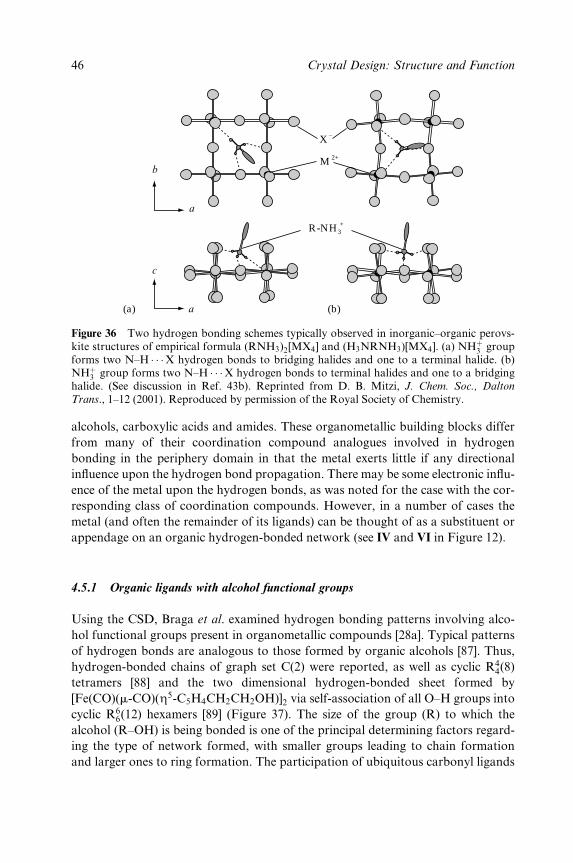
b
a
c
a
M 2+
R-NH +3
X −
(a) (b)
Figure 36 Two hydrogen bonding schemes typically observed in inorganic±organic perovs-kite structures of empirical formula (RNH3)2[MX4] and (H3NRNH3)[MX4]. (a) NH�3 groupforms two N±H � � �X hydrogen bonds to bridging halides and one to a terminal halide. (b)NH�3 group forms two N±H � � �X hydrogen bonds to terminal halides and one to a bridginghalide. (See discussion in Ref. 43b). Reprinted from D. B. Mitzi, J. Chem. Soc., Dalton
Trans., 1±12 (2001). Reproduced by permission of the Royal Society of Chemistry.
alcohols, carboxylic acids and amides. These organometallic building blocks differ
from many of their coordination compound analogues involved in hydrogen
bonding in the periphery domain in that the metal exerts little if any directional
in¯uence upon the hydrogen bond propagation. There may be some electronic in¯u-
ence of the metal upon the hydrogen bonds, as was noted for the case with the cor-
responding class of coordination compounds. However, in a number of cases the
metal (and often the remainder of its ligands) can be thought of as a substituent or
appendage on an organic hydrogen-bonded network (see IV and VI in Figure 12).
4.5.1 Organic ligands with alcohol functional groups
Using the CSD, Braga et al. examined hydrogen bonding patterns involving alco-
hol functional groups present in organometallic compounds [28a]. Typical patterns
of hydrogen bonds are analogous to those formed by organic alcohols [87]. Thus,
hydrogen-bonded chains of graph set C(2) were reported, as well as cyclic R44(8)
tetramers [88] and the two dimensional hydrogen-bonded sheet formed by
[Fe(CO)(m-CO)(Z5-C5H4CH2CH2OH)]2 via self-association of all O±H groups into
cyclic R66(12) hexamers [89] (Figure 37). The size of the group (R) to which the
alcohol (R±OH) is being bonded is one of the principal determining factors regard-
ing the type of network formed, with smaller groups leading to chain formation
and larger ones to ring formation. The participation of ubiquitous carbonyl ligands
46 Crystal Design: Structure and Function

Figure 37 Part of hydrogen-bonded sheet formed by [Fe2(Z5-C5H4CH2CH2OH)2(CO)2(m-CO)2] [89] showing R6
6(12) O±H � � �O hydrogen-bonded rings. Adapted with permis-sion from Figure 11c in D. Braga, F. Grepioni, P. Sabatino and G. R. Desiraju, Organo
metallics, 13, 3532±43 (1994). Copyright 1994 American Chemical Society.
in hydrogen-bonded networks involving O±H � � �OwwwC(M) hydrogen bonds is also
documented [28a].
In an effort to use organometallic alcohols in crystal synthesis, Braga and Gre-
pioni in collaboration with Walther and co-workers have reported the synthesis
and structural characterization of a series of prop-2-yn-1-ol complexes of Pt and
Ni [90]. The hydrogen bonding patterns in the structures of these compounds again
resemble the aforementioned chain and ring supramolecular synthons known for
alcohols in general. These patterns are then compared with patterns observed
for the corresponding organic prop-2-yn-1-ols [90]. A number of 1, 10-ferrocene-
diols have been prepared and the hydrogen bonding patterns of their crystal struc-
tures analysed. These include the structures of Fe(Z5-C5H4CH2OH)2 [91] and
Fe(Z5-C5Me4CH2OH)2 [92], which form a 1D C(2) network and a 3D network,
respectively, through O±H � � �O hydrogen bonds. The predominant work involving
such diol systems is due to Glidewell and co-workers [93,94], who examined the
series Fe(Z5-C5H4C(R)(R0)OH)2, R � R0 � Ph [93a]; R � R0 �Me [93b]; R � Ph,
R0 �Me (racemic) [93c] and R � Me, R0 � H (racemic) [93c], all of which form
Hydrogen Bonds: Application to Crystal Design 47

discrete dimers via R44(8) hydrogen-bonded rings. A more recent report by Braga
et al. describes the structure of enantiomerically pure Fe(Z5-C5H4CH(CH3)OH)2,
which forms a 1D hydrogen-bonded chain [95]. Co-crystallization of
Fe(Z5-C5H4CPh2OH)2 can be achieved with a variety of diamine and polyamine
hydrogen bond acceptors resulting in O±H � � �N hydrogen-bonded adducts,
although rarely in extended networks [94].
4.5.2 Carboxyl- and carboxylate-bearing ligands
Patterns of hydrogen bond formation for organometallic complexes with carboxyl-
substituted ligands have been compared with those of organic carboxylic acids
showing that the R22(8) rings and C(4) chains prevalent in the latter are also
common in the former [28a]. In cases where more than one ligand carboxyl group
is present, hydrogen-bonded networks are found. Most interesting are the strong
similarities between the networks formed by maleic acid [96] and Fe(Z2-maleic
acid)(CO)4 [97] and similarly between those of fumaric acid (two polymorphs) [98]
and Fe(Z2-fumaric acid)(CO)4 (two polymorphs) [97,99]. In a similar vein to these
organic/organometallic pairings, Brammer et al. have prepared and crystallized the
(Z6-arene)Cr(CO)3 complexes of the well-known series of benzene carboxylic acids:
benzoic, terephthalic, isophthalic and trimesic acid (XXXIII ± XXXVI, Figure 38)
[27a] . For XXXIII, a centrosymmetric carboxylic acid dimer is formed by associ-
ation of (Z6-arene)Cr(CO)3 molecules. The dimers then associate via C±H � � �Ohydrogen bonds [100]. Efforts to prepare solvent free crystals of XXXIV ± XXXVI
have to date been unsuccessful, owing to the poor solubility of these compounds in
media other than polar solvents that can compete for hydrogen bond formation.
Thus, XXXIV and XXXV have been crystallized as their dimethyl sulfoxide
(DMSO) and dimethylformamide (DMF) solvates, XXXIV�2DMSO and
XXXV � 2DMF, respectively. Hydrogen bonding between the carboxyl groups and
the solvent molecules prevents direct association between carboxyl groups. How-
ever, the disolvated organometallic molecules serve as three-component building
blocks for further association via a network of C±H � � �O hydrogen bonds.
CO
OH
Cr
CO
C
O
CO
C O
OHC
OHO
C
OHO
CO
HO
XXXIII XXXIV XXXV XXXVI
Cr
CO
C
O
CO
C O
OH
Cr
CO
C
O
CO
C
OHO
CO
OH
Cr
CO
C
O
CO
Figure 38 Organometallic benzene carboxylic acid building blocks: chromium tricarbonylcomplexes [27a].
48 Crystal Design: Structure and Function
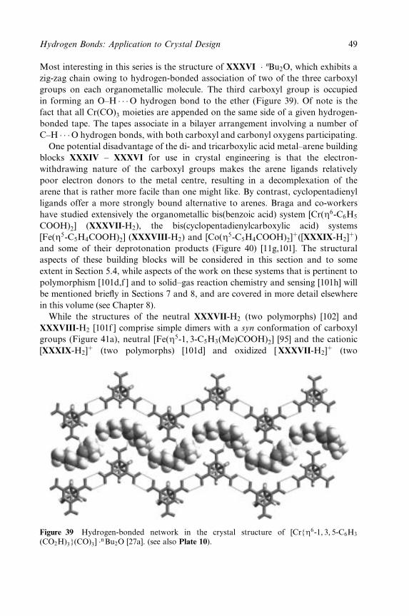
Most interesting in this series is the structure of XXXVI � nBu2O, which exhibits a
zig-zag chain owing to hydrogen-bonded association of two of the three carboxyl
groups on each organometallic molecule. The third carboxyl group is occupied
in forming an O±H � � �O hydrogen bond to the ether (Figure 39). Of note is the
fact that all Cr(CO)3 moieties are appended on the same side of a given hydrogen-
bonded tape. The tapes associate in a bilayer arrangement involving a number of
C±H � � �O hydrogen bonds, with both carboxyl and carbonyl oxygens participating.
One potential disadvantage of the di- and tricarboxylic acid metal±arene building
blocks XXXIV ± XXXVI for use in crystal engineering is that the electron-
withdrawing nature of the carboxyl groups makes the arene ligands relatively
poor electron donors to the metal centre, resulting in a decomplexation of the
arene that is rather more facile than one might like. By contrast, cyclopentadienyl
ligands offer a more strongly bound alternative to arenes. Braga and co-workers
have studied extensively the organometallic bis(benzoic acid) system [Cr(Z6-C6H5
COOH)2] (XXXVII-H2), the bis(cyclopentadienylcarboxylic acid) systems
[Fe(Z5-C5H4COOH)2] (XXXVIII-H2) and [Co(Z5-C5H4COOH)2]�([XXXIX-H2]
�)
and some of their deprotonation products (Figure 40) [11g,101]. The structural
aspects of these building blocks will be considered in this section and to some
extent in Section 5.4, while aspects of the work on these systems that is pertinent to
polymorphism [101d,f ] and to solid±gas reaction chemistry and sensing [101h] will
be mentioned brie¯y in Sections 7 and 8, and are covered in more detail elsewhere
in this volume (see Chapter 8).
While the structures of the neutral XXXVII-H2 (two polymorphs) [102] and
XXXVIII-H2 [101f ] comprise simple dimers with a syn conformation of carboxyl
groups (Figure 41a), neutral [Fe(Z5-1, 3-C5H3(Me)COOH)2] [95] and the cationic
[XXXIX-H2]� (two polymorphs) [101d] and oxidized [ XXXVII-H2]
� (two
Figure 39 Hydrogen-bonded network in the crystal structure of [Cr{Z6-1, 3, 5-C6H3
(CO2H)3}(CO)3] �nBu2O [27a]. (see also Plate 10).
Hydrogen Bonds: Application to Crystal Design 49
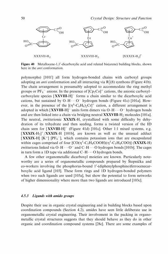
CO
OH
Fe
CO
HOCO
HOCo+
CO
OH
Cr
C O
OH
CO
HO
[XXXIX-H2]+XXXVIII-H2XXXVII-H2
Figure 40 Metallocene-1,10-dicarboxylic acid and related bis(arene) building blocks, shownhere in the anti conformation.
polymorphs) [101f ] all form hydrogen-bonded chains with carboxyl groups
adopting an anti conformation and all interacting via R22(8) synthons (Figure 41b).
The chain arrangement is presumably adopted to accommodate the ring methyl
groups or PF6ÿ anions. In the presence of [Cp2Co]� cations, the anionic carboxyl±
carboxylate species [ XXVIII-H]ÿ forms a chain similar to the dicarboxylic acid
cations, but sustained by O±H � � �Oÿ hydrogen bonds (Figure 41c) [101a]. How-
ever, in the presence of the [(Z6-C6H6)2Cr]� cation, a different arrangement is
adopted in which [ XXVIII-H]ÿ units form dimers via O±H � � �Oÿ hydrogen bonds
and are then linked into a chain via bridging neutral XXXVIII-H2 molecules [101a].
The neutral, zwitterionic XXXIX-H, crystallized with some dif®culty by dehy-
dration of its trihydrate and then seeding, forms a twisted version of the ID
chain seen for [ XXVIII-H]ÿ (Figure 41d) [101c]. Other 1:1 mixed systems, e.g.
[ XXXIX-H2]�=XXXIX-H [101b], are known as well as the unusual adduct
[ XXXIX-H] [K�] [PF6ÿ], which contains potassium ions that are encapsulated
within cages comprised of four [CO(Z5-C5H4COOH)(Z5-C5H4COO)] (XXXIX-H)
zwitterions linked via O±H � � �Oÿ and C±H � � �O hydrogen bonds [101b]. The cages
in turn form a 1D tape via additional C±H � � �O hydrogen bonds.
A few other organometallic dicarboxyl moieties are known. Particularly note-
worthy are a series of organometallic compounds prepared by SÏtepnicÏka and
co-workers involving the phosphorus-bound 10-(diphenylphosphino)ferrocenecar-
boxylic acid ligand [103]. These form rings and 1D hydrogen-bonded polymers
when two such ligands are used [103a], but show the potential to form networks
of higher dimensionality where more than two ligands are introduced [103c].
4.5.3 Ligands with amido groups
Despite their use in organic crystal engineering and in building blocks based upon
coordination compounds (Section 4.2), amides have seen little deliberate use in
organometallic crystal engineering. Their involvement in the packing in organo-
metallic crystal structures suggests that they should behave as they do in other
organic and coordination compound systems [28c]. There are some examples of
50 Crystal Design: Structure and Function
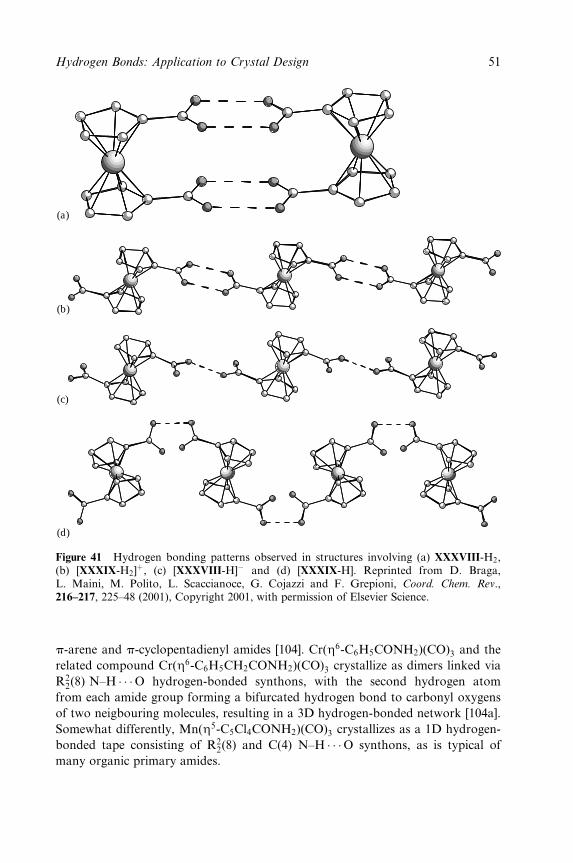
(a)
(b)
(c)
(d)
Figure 41 Hydrogen bonding patterns observed in structures involving (a) XXXVIII-H2,(b) [XXXIX-H2]
�, (c) [XXXVIII-H]ÿ and (d) [XXXIX-H]. Reprinted from D. Braga,L. Maini, M. Polito, L. Scaccianoce, G. Cojazzi and F. Grepioni, Coord. Chem. Rev.,216±217, 225±48 (2001), Copyright 2001, with permission of Elsevier Science.
p-arene and p-cyclopentadienyl amides [104]. Cr(Z6-C6H5CONH2)(CO)3 and the
related compound Cr(Z6-C6H5CH2CONH2)(CO)3 crystallize as dimers linked via
R22(8) N±H � � �O hydrogen-bonded synthons, with the second hydrogen atom
from each amide group forming a bifurcated hydrogen bond to carbonyl oxygens
of two neigbouring molecules, resulting in a 3D hydrogen-bonded network [104a].
Somewhat differently, Mn(Z5-C5Cl4CONH2)(CO)3 crystallizes as a 1D hydrogen-
bonded tape consisting of R22(8) and C(4) N±H � � �O synthons, as is typical of
many organic primary amides.
Hydrogen Bonds: Application to Crystal Design 51

5 WEAK HYDROGEN BONDS
As weak hydrogen bonds by de®nition do not contribute substantially to overall
crystal cohesion on an individual basis, their primary importance lies in their
abundance. Thus, their combined energetic contribution in a given crystal may be
substantial, as can be the case with other weak interactions, which at ®rst consid-
eration may seem to be in the realm of `background noise' compared with
stronger interactions that are (rightfully) given greater consideration in crystal
design and synthesis. However, unlike van der Waals interactions, for example,
weak hydrogen bonds, the C±H � � �O hydrogen bond being the prime example
[105], are directional in nature [106] and exhibit attractive forces at fairly long
distances, including beyond the nominal van der Waals contact distance [14e]. It
is now recognized that hydrogen bonding is not con®ned to the electronegative
elements in the upper right-hand corner of the Periodic Table, but that a wide
range of elements can participate in hydrogen bonds, many of these forming
relatively weak interactions [14e]. However, in this section the discussion of weak
hydrogen bond donors will be con®ned to C±H groups, particularly the ubiqui-
tous C±H � � �OC(M) hydrogen bonds of organometallic compounds. Weak accep-
tors, including phenyl, cyclopentadienyl and alkyne groups, that use ®lled p-
orbitals rather than lone pairs to participate in hydrogen bonds, will also be
discussed. It should be stated that in many if not all of the systems discussed in
Section 4, weak hydrogen bonds are present in conjunction with the stronger
counterparts. However, as in organic crystal engineering, the use of weak hydro-
gen bonds as the primary organizing force in inorganic crystal design is somewhat
dif®cult to implement and in most cases will not be the preferred strategy. Never-
theless, weak hydrogen bonds should not be ignored as they will frequently be
present whether by design or not. Ideally they should be used to work in harmony
with stronger forces in the overall crystal design. As AakeroÈy and Leinen have
observed with weak hydrogen bonds [19], `Typically, the directional preferences of
these bonds are satis®ed within the geometrical constraints of stronger hydrogen
bonds . . . Furthermore, C±H � � �X interactions can tilt the balance between several
options of stronger bonded networks, thus acting as an important ``steering
force'' in solid-state assembly'.
5.1 M2(m2-CH2) and M3(m3-CH) Groups in C±H � � �O Hydrogen Bonds
In Section 4.1.1, (M)N±H and (M)O±H hydrogen bond donors were discussed in
the context of the in¯uence of metal coordination upon donor capability of such
groups (e.g. OH2 vs M±OH2). This discussion is now extended to (M)C±H
donors. A useful comparison between the hydrogen bonding capabilities of
M2(m2-CH2) and M3(m3-CH) groups has been carried out by Braga et al. using
the CSD to examine the metrics of C±H � � �O hydrogen bonds, in most cases
52 Crystal Design: Structure and Function
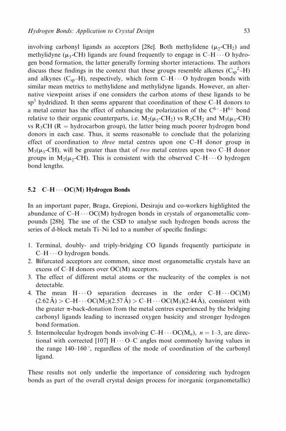
involving carbonyl ligands as acceptors [28e]. Both methylidene (m2-CH2) and
methylidyne (m3-CH) ligands are found frequently to engage in C±H � � �O hydro-
gen bond formation, the latter generally forming shorter interactions. The authors
discuss these ®ndings in the context that these groups resemble alkenes (Csp2±H)
and alkynes (Csp±H), respectively, which form C±H � � �O hydrogen bonds with
similar mean metrics to methylidene and methylidyne ligands. However, an alter-
native viewpoint arises if one considers the carbon atoms of these ligands to be
sp3 hydridized. It then seems apparent that coordination of these C±H donors to
a metal center has the effect of enhancing the polarization of the Cdÿ±Hd� bond
relative to their organic counterparts, i.e. M2(m2-CH2) vs R2CH2 and M3(m3-CH)
vs R3CH (R � hydrocarbon group), the latter being much poorer hydrogen bond
donors in each case. Thus, it seems reasonable to conclude that the polarizing
effect of coordination to three metal centres upon one C±H donor group in
M3(m3-CH), will be greater than that of two metal centres upon two C±H donor
groups in M2(m2-CH). This is consistent with the observed C±H � � �O hydrogen
bond lengths.
5.2 C±H � � �OC(M) Hydrogen Bonds
In an important paper, Braga, Grepioni, Desiraju and co-workers highlighted the
abundance of C±H � � �OC(M) hydrogen bonds in crystals of organometallic com-
pounds [28b]. The use of the CSD to analyse such hydrogen bonds across the
series of d-block metals Ti±Ni led to a number of speci®c ®ndings:
1. Terminal, doubly- and triply-bridging CO ligands frequently participate in
C±H � � �O hydrogen bonds.
2. Bifurcated acceptors are common, since most organometallic crystals have an
excess of C±H donors over OC(M) acceptors.
3. The effect of different metal atoms or the nuclearity of the complex is not
detectable.
4. The mean H � � �O separation decreases in the order C±H � � �OC(M)
(2:62 ÊA) > C±H � � �OC(M2)(2:57 ÊA) > C±H � � �OC(M3)(2:44 ÊA), consistent with
the greater p-back-donation from the metal centres experienced by the bridging
carbonyl ligands leading to increased oxygen basicity and stronger hydrogen
bond formation.
5. Intermolecular hydrogen bonds involving C±H � � �OC(Mn), n � 1±3, are direc-
tional with corrected [107] H � � �O±C angles most commonly having values in
the range 140±160 8, regardless of the mode of coordination of the carbonyl
ligand.
These results not only underlie the importance of considering such hydrogen
bonds as part of the overall crystal design process for inorganic (organometallic)
Hydrogen Bonds: Application to Crystal Design 53
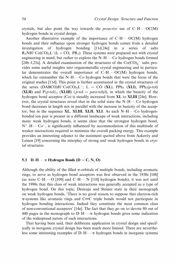
crystals, but also point the way towards the proactive use of C±H � � �OC(M)
hydrogen bonds in crystal design.
Another illustrative example of the importance of C±H � � �OC(M) hydrogen
bonds and their in¯uence upon stronger hydrogen bonds comes from a detailed
investigation of hydrogen bonding [11d,24e] in a series of salts
R3NH�Co(CO)3Lÿ(L � CO, PR3). These systems were prepared not with crystal
engineering in mind, but rather to explore the N±H � � �Co hydrogen bonds formed
[24b±f,25a]. A detailed examination of the structures of the Co(CO)4ÿ salts pro-
vides some useful insights into organometallic crystal engineering and in particu-
lar demonstrates the overall importance of C±H � � �OC(M) hydrogen bonds,
which far outnumber the N±H � � �Co hydrogen bonds that were the focus of the
original studies [11d]. This point is further accentuated in the crystal structures of
the series (DABCO)H�Co(CO)3Lÿ; L � CO (XL), PPh3 (XLI), PPh2(p-tol)
(XLII) and P{p-tol}3 (XLIII) ( p-tol � para-tolyl), in which the basicity of the
hydrogen bond acceptor (Co) is steadily increased from XL to XLIII [24e]. How-
ever, the crystal structures reveal that in the solid state the N±H � � �Co hydrogen
bond decreases in length not in parallel with the increase in basicity of the accep-
tor, but in the sequence XL, XLIII, XLII, XLI. As each N±H � � �Co hydrogen-
bonded ion pair is present in a different landscape of weak interactions, including
many weak hydrogen bonds, it seems clear that the strongest hydrogen bond,
N�±H � � �Coÿ, is signi®cantly in¯uenced by accommodation of this multitude of
weaker interactions required to minimize the overall packing energy. This example
provides an interesting adjunct to the statement quoted above from AakeroÈy and
Leinen [19] concerning the interplay of strong and weak hydrogen bonds in crys-
tal structures.
5.3 D±H � � �p Hydrogen Bonds (D � C, N, O)
Although the ability of the ®lled p-orbitals of multiple bonds, including aromatic
rings, to serve as hydrogen bond acceptors was ®rst observed in the 1930s [108]
(as were C±H � � �O [109] and C±H � � �N [110] hydrogen bonds), it was not until
the 1990s that this class of weak interactions was generally accepted as a type of
hydrogen bond. On this topic, Desiraju and Steiner state in their monograph
on weak hydrogen bonds, `There is no good reason to suppose that electron-rich
p-systems like aromatic rings and CwwwC triple bonds would not participate in
hydrogen bonding interactions. Indeed they constitute the most common class
of non-conventional acceptors' [14e]. The fact that they go on to devote 80 out of
440 pages in the monograph to D±H � � �p hydrogen bonds gives some indication
of the widespread nature of such interactions.
That having been said, their deliberate application in crystal design and specif-
ically in inorganic crystal design has been much more limited. There are neverthe-
less some interesting examples of D±H � � �p hydrogen bonds in inorganic systems
54 Crystal Design: Structure and Function
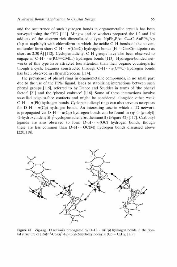
and the occurrence of such hydrogen bonds in organometallic crystals has been
surveyed using the CSD [111]. Mingos and co-workers prepared the 1:2 and 1:4
adducts of the electron-rich dimetallated alkyne NpPh2PAu±CwwwC±AuPPh2Np
(Np � naphthyl) with chloroform in which the acidic C±H bonds of the solvent
molecules form short C±H � � �p(CwwwC) hydrogen bonds [H � � �Cwww
C(midpoint) as
short as 2.30AÊ ] [112]. Cyclopentadienyl C±H groups have also been observed to
engage in C±H � � �p(RCwwwCMLn) hydrogen bonds [113]. Hydrogen-bonded net-
works of this type have attracted less attention than their organic counterparts,
though a cyclic hexamer constructed through C±H � � �p(CwwwC) hydrogen bonds
has been observed in ethynylferrocene [114].
The prevalence of phenyl rings in organometallic compounds, in no small part
due to the use of the PPh3 ligand, leads to stabilizing interactions between such
phenyl groups [115], referred to by Dance and Scudder in terms of `the phenyl
factor' [21] and the `phenyl embrace' [116]. Some of these interactions involve
so-called edge-to-face contacts and might be considered alongside other weak
C±H � � �p(Ph) hydrogen bonds. Cyclopentadienyl rings can also serve as acceptors
for D±H � � �p(Cp) hydrogen bonds. An interesting case in which a 1D network
is propagated via O±H � � �p(Cp) hydrogen bonds can be found in (Z5-1-{p-tolyl}
-2-hydroxyindenyl)(Z5-cyclopentadienyl)ruthenium(II) (Figure 42) [117]. Carbonyl
ligands are also observed to form D±H � � �p(OC) hydrogen bonds, though
these are less common than D±H � � �OC(M) hydrogen bonds discussed above
[22b,118].
Figure 42 Zig-zag 1D network propagated by O±H � � �p(Cp) hydrogen bonds in the crys-tal structure of [Ru(Z5-Cp)(Z5-1-p-tolyl-2-hydroxyindenyl)] (Cp � C5H5) [117].
Hydrogen Bonds: Application to Crystal Design 55
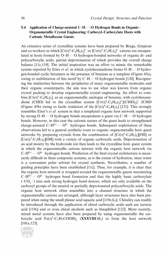
5.4 Application of Charge-assisted C±H � � �O Hydrogen Bonds in Organic±
Organometallic Crystal Engineering: Carboxyl±Carboxylate Hosts with
Cationic Metallocene Guests
An extensive series of crystalline systems have been prepared by Braga, Grepioni
and co-workers in which [Cr(Z6-C6H6)2]� or [Co(Z5-C5H5)2]
� cations are encapsu-
lated in hosts formed by O±H � � �O hydrogen-bonded networks of organic di- and
polycarboxylic acids, partial deprotonation of which provides the overall charge
balance [11c,119]. The initial inspiration was an effort to mimic the remarkable
system reported by Etter et al. in which cyclohexanedione forms O±H � � �O hydro-
gen-bonded cyclic hexamers in the presence of benzene as a template (Figure 43a),
owing to stabilization of this motif by C±H � � �O hydrogen bonds [120]. Recogniz-
ing the similarities between the peripheries of many organometallic molecules and
their organic counterparts, the aim was to use what was known from organic
crystal packing to develop organometallic crystal engineering. An effort to com-
bine [Cr(Z6-C6H6)2], as an organometallic analogue of benzene, with cyclohexane-
dione (CHD) led to the crystalline system [Cr(Z6-C6H6)2]�[(CHD)2]
ÿ�2CHD
(Figure 43b) owing to facile oxidation of the [Cr(Z6-C6H6)2] [121]. This strongly
resembles Etter's et al. system in that a templated organic host network supported
by strong O±H � � �O hydrogen bonds encapsulates a guest via C±H � � �O hydrogen
bonds. However, in this case the cationic nature of the guest leads to strengthened
charge-assisted C±Hd� � � �Odÿ hydrogen bonds. Subsequent exploitation of these
observations led to a general synthetic route to organic±organometallic host±guest
networks by preparing crystals from the combination of [Cr(Z6-C6H6)2][OH] or
[Co(Z5-C5H5)2][OH] with a variety of organic carboxylic acids. Deprotonation of
an acid moiety by the hydroxide ion then leads to the crystalline host±guest system
in which the organometallic cations interact with the organic host network via
C±Hd� � � �Odÿ hydrogen bonds. Prediction of the ®nal crystal architecture is neces-
sarily dif®cult in these composite systems, as is the extent of hydration, since water
is a convenient polar solvent for crystal synthesis. Nevertheless, a number of
guiding principles have been established [11c]. Thus, for example, it is clear that
the organic host network is wrapped around the organometallic guests maximizing
C±Hd� � � �Odÿ hydrogen bond formation and that the highly basic carboxylate
(±CO ÿ2 ) sites seek strong hydrogen bond donors, which are only available on the
carboxyl groups of the neutral or partially deprotonated polycarboxylic acids. The
organic host network often assembles into a channel structure in which the
organometallic cations are arranged, although layer structures have also been pre-
pared when using the small planar acid squaric acid [119e,h,i]. Chirality can readily
be introduced through the application of chiral carboxylic acids such are tartaric
acid [119c] and or even chiral alcohols such as binaphthol [122]. More recently,
mixed metal systems have also been prepared by using organometallic the car-
boxylic acid Fe(Z5-C5H5COOH)2 (XXXVIII-H2) to form the host network
[101a,123].
56 Crystal Design: Structure and Function
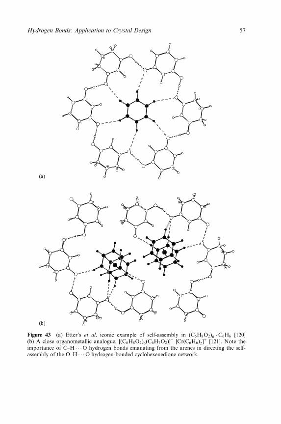
(a)
(b)
Figure 43 (a) Etter's et al. iconic example of self-assembly in (C6H8O2)6 � C6H6 [120](b) A close organometallic analogue, [(C6H8O2)6(C6H7O2)]
ÿ [Cr(C6H6)2]� [121]. Note the
importance of C±H � � �O hydrogen bonds emanating from the arenes in directing the self-assembly of the O±H � � �O hydrogen-bonded cyclohexenedione network.
Hydrogen Bonds: Application to Crystal Design 57
6 DIRECT INVOLVEMENT OF METALS IN HYDROGEN BONDS
As noted in Section 3.3, spectroscopic and crystallographic evidence, principally
in the past decade, has led to the recognition that metals can participate directly
in hydrogen bonds as either the donor, M±H � � �A [23], or acceptor, D±H � � �M[13,24,25]. These interactions are of importance in the study of protonation of
metal centres and the deprotonation of metal hydrides, but do they have a poten-
tial role to play in inorganic crystal design? Surveys of the CSD suggest that there
may be many examples of such interactions [23e,25k]. M±H � � �O hydrogen bonds
are generally regarded as being fairly weak, similar to C±H � � �O hydrogen
bonds, and a 1996 CSD survey revealed only 17 crystal structures with (M)H � � �Odistances of less than 2.8 AÊ (eight such interactions at less than 2.6 AÊ ) [23e].
Hence, unlike C±H � � �O hydrogen bonds, their weakness is not compensated for
by their abundance. Hence their role in inorganic crystal design is likely to be
negligible. The prospects are slightly better for D±H � � �M hydrogen bonds. These
are stronger, reaching 7 kcal/mol in solution for O±H � � �M hydrogen bonds
between neutral molecules and undoubtedly more when charge-assisted. Hence
strength is not the issue. Although they are also more abundant than their
M±H � � �O counterparts [25 k], the question of the applicability of D±H � � �Mhydrogen bonds in crystal design does rest upon a realistic assessment of the
availability of such hydrogen bonds. At present D±H � � �M hydrogen bonds have
been observed for a limited number of electron-rich transition metal centres [25]
and require, in addition, sterically accessible (d-orbital) lone pairs on the metal
atom at the centre of a metal complex. Their use in crystal design is, therefore,
likely to be at best very limited compared with hydrogen bonds involving the
Ligand and Periphery Domains. An added deterrent to the use of Metal Domain
hydrogen bonds is the synthesis of the metal complexes involved. While crystal
engineering has evolved from what is sometimes referred to as `Aldrich chemistry',
i.e. the use of commercially available compounds as building blocks, to the design
and (conventional) synthesis of building blocks, the organometallic synthesis and
potential air sensitivity of the many metal complexes able to participate in
M±H � � �A and D±H � � �M hydrogen bonds is unlikely to provide an incentive to
seek this approach to crystal design. These comments do not undermine the
importance of such interactions in organometallic chemistry, but merely put a
realistic face upon their potential use in inorganic crystal design.
Another interaction sometimes discussed alongside hydrogen bonds unique to
inorganic or organometallic crystals is intermolecular X±H s-bond complexation,
sometimes confusingly so since these interactions are fundamentally different from
hydrogen bonds [12a]. The interactions of X±H s-bonds with electron-de®cient
transition metal centres has been widely studied and is important in the activation
of such bonds by transition metals [124]. The most common among these are for
X � B, C, Si, the emphasis in most studies being on intramolecular interactions.
An indication that C±H s-bonds form weak intermolecular interactions with
58 Crystal Design: Structure and Function
metal centres in a number of crystal structures of organometallic compounds has
been established by a survey of the CSD [25k]. However, for analogous reasons to
those given in the above discussion of M±H � � �A and D±H � � �M hydrogen bonds,
the role of intermolecular X±H s-bond complexation is not of general signi®cance
in crystal design.
7 FUNCTION AND PROPERTIES
A primary goal in crystal engineering is the ability to design and synthesize crys-
talline materials with a high degree of predictability. This goal is being approached
for certain well-de®ned classes of compounds for which the structural variables
can be well de®ned and are well understood. However, reaching this goal more
broadly for all classes of compounds, and all types of building blocks, still lies
well in the future. The purpose of the desired structural control, of course, returns
us to the intimate link between structure (and composition) and properties.
Microscopic structure can in principle be controlled in order to tune the physical
and chemical properties of a material. However, we cannot afford to wait until
full control of structure of a wide range of materials is achieved before consider-
ing their properties; the two must be developed side by side to some extent. A
number of approaches can be taken.
One can take building blocks with known properties/function and endeavour to
design a crystalline solid that incorporates these units with the aim of instilling
these molecular properties or some cooperative version thereof into the new
material. An example of such a case is the incorporation of transition metal
centres with unpaired electrons into well-de®ned networks in which the spins of
these electrons can interact to yield desirable magnetic properties, which may then
be further re®ned by tuning the overall structure. Similarly, one might envisage
taking a catalytically active molecule and modifying its periphery so as to incorp-
orate it into a porous crystalline material that would permit control of entry and
exit sites to the catalyst, but still preserve the molecular catalytic function.
An alternative approach involves designing networks to exhibit a property or
perform a function not inherent in the building blocks used. One might consider
the design of porous solids or lamellar solids for host±guest chemistry, separ-
ations, etc., to fall into this category, since these properties are not inherent in the
building blocks used. However, such properties of the ®nal solid may be enhanced
by the appropriate choice of building blocks, such as those with functionality
capable of serving as effective binding sites.
A third approach arises when pursuing primarily structural objectives is
coupled with keen observation, and examination and testing of the properties of
materials synthesized. A simple example involves the common situation in which
solvent molecules are incorporated into cavities in network solids. Further exam-
ination to see if the solvent can be removed or replaced by other guests is often
Hydrogen Bonds: Application to Crystal Design 59
warranted. More quantitative studies, e.g. using differential scanning calorimetry
(DSC) or thermogravimetric analysis (TGA), are also useful in such circum-
stances.
While crystal engineering is beginning to have its successes in terms of deliver-
ing properties in designed crystalline materials, this aspect of the ®eld is very
much in its infancy. The area of crystal design covered in this chapter, that of
hydrogen-bonded inorganic materials, is less well developed than either its organic
counterpart or that of inorganic coordination networks, and can bene®t from
aspects of each of these approaches. Nevertheless, there are some interesting and
promising developments in the properties of inorganic hydrogen-bonded mater-
ials, as highlighted in the remainder of this section.
Returning to the topochemical roots of crystal engineering, recent examples
have illustrated that N±H � � �H±E hydrogen bonds (E � B, Ga) in crystalline
solids can be used to form N±E bonds in the solid state by elimination of gaseous
H2. This has been illustrated by Gladfelter and co-workers in the preparation of
nanocrystalline gallium nitride via N±H � � �H±Ga hydrogen bonds in cyclotria-
gallazane, (H2GaNH2)3 [46h,i], and by Jackson and co-workers in preparing
B±N-bonded networks unattainable by other means [46c±e].
The work of Mitzi has shown that inorganic±organic hybrid perovskites in
which inorganic layers consisting of corner-sharing metal halide octahedra and
linked by cationic organic layers are capable of exhibiting a variety of potentially
useful magnetic, electrical and optical properties [43]. The organic±inorganic inter-
face consists of many N±H � � �X(M) hydrogen bonds (X � halogen), leading to
well organized crystalline materials, which can be characterized by single-crystal
diffraction methods (see Section 4.4.2). Properties identi®ed in such materials
include semiconductor and high electron mobilities in Sn(II) halide-based hybrids
[125]. Novel optical properties have also been observed for such hybrid materials
based upon other divalent Group 14 halides [126] and the ®rst-row d-block
metals, M(II), have provided useful model systems for studying low-dimensional
magnetic properties [127].
Neve and co-workers have also made use of hydrogen-bonded perhalometallate
ions, but in this case using salts mononuclear ions linked by weak charge-assisted
C±H � � �X(M) hydrogen bonds from alkylpyridinium cations [128]. The use of
cations with long-chain alkyl substituents leads to liquid crystalline behaviour in
these salts [128a±c].
Recent reports have also shown the potential for applications in sensing shown
by metal-containing hydrogen-bonded crystalline solids. Albrecht, van Koten and
co-workers have reported a remarkable crystalline organoplatinum `pincer-ligand'
complex XLIV [44a] that is capable of reversibly binding SO2 [129] (Chapter 9).
The complex assembles into parallel 1D tapes via O±H � � �Cl(Pt) hydrogen bonds
such that all the organometallic building blocks within one tape are coplanar
(Figure 44). The tapes are then arranged in a buckled sheet structure. Absorption
of SO2 is accompanied by a colour change from colourless XLIV to orange XLV,
60 Crystal Design: Structure and Function
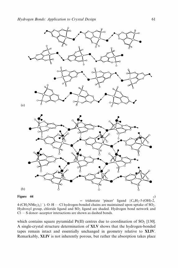
(a)
(b)
Figure 44 Crystal structures (a) [Pt(NCN-OH)Cl] XLIV [44a] and (b) [Pt(SO2)(NCN-OH)Cl] XLV [129a,b] (NCN � tridentate `pincer' ligand {C6H2-5-(OH)-2,4-(CH2NMe2)2}
ÿ). O±H � � �Cl hydrogen-bonded chains are maintained upon uptake of SO2.Hydroxyl group, chloride ligand and SO2 ligand are shaded. Hydrogen bond network andCl � � �S donor±acceptor interactions are shown as dashed bonds.
which contains square pyramidal Pt(II) centres due to coordination of SO2 [130].
A single-crystal structure determination of XLV shows that the hydrogen-bonded
tapes remain intact and essentially unchanged in geometry relative to XLIV.
Remarkably, XLIV is not inherently porous, but rather the absorption takes place
Hydrogen Bonds: Application to Crystal Design 61
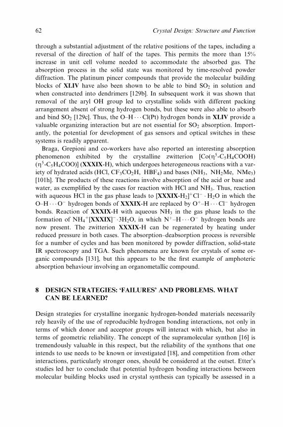
through a substantial adjustment of the relative positions of the tapes, including a
reversal of the direction of half of the tapes. This permits the more than 15%
increase in unit cell volume needed to accommodate the absorbed gas. The
absorption process in the solid state was monitored by time-resolved powder
diffraction. The platinum pincer compounds that provide the molecular building
blocks of XLIV have also been shown to be able to bind SO2 in solution and
when constructed into dendrimers [129b]. In subsequent work it was shown that
removal of the aryl OH group led to crystalline solids with different packing
arrangement absent of strong hydrogen bonds, but these were also able to absorb
and bind SO2 [129c]. Thus, the O±H � � �Cl(Pt) hydrogen bonds in XLIV provide a
valuable organizing interaction but are not essential for SO2 absorption. Import-
antly, the potential for development of gas sensors and optical switches in these
systems is readily apparent.
Braga, Grepioni and co-workers have also reported an interesting absorption
phenomenon exhibited by the crystalline zwitterion [Co(Z5-C5H4COOH)
(Z5-C5H4COO)] (XXXIX-H), which undergoes heterogeneous reactions with a var-
iety of hydrated acids (HCl, CF3CO2H, HBF4) and bases (NH3, NH2Me, NMe3)
[101h]. The products of these reactions involve absorption of the acid or base and
water, as exempli®ed by the cases for reaction with HCl and NH3. Thus, reaction
with aqueous HCl in the gas phase leads to [XXXIX-H2]�Clÿ �H2O in which the
O±H � � �Oÿ hydrogen bonds of XXXIX-H are replaced by O�±H � � �Clÿ hydrogen
bonds. Reaction of XXXIX-H with aqueous NH3 in the gas phase leads to the
formation of NH4�[XXXIX]ÿ�3H2O, in which N�±H � � �Oÿ hydrogen bonds are
now present. The zwitterion XXXIX-H can be regenerated by heating under
reduced pressure in both cases. The absorption±deabsorption process is reversible
for a number of cycles and has been monitored by powder diffraction, solid-state
IR spectroscopy and TGA. Such phenomena are known for crystals of some or-
ganic compounds [131], but this appears to be the ®rst example of amphoteric
absorption behaviour involving an organometallic compound.
8 DESIGN STRATEGIES: `FAILURES' AND PROBLEMS. WHAT
CAN BE LEARNED?
Design strategies for crystalline inorganic hydrogen-bonded materials necessarily
rely heavily of the use of reproducible hydrogen bonding interactions, not only in
terms of which donor and acceptor groups will interact with which, but also in
terms of geometric reliability. The concept of the supramolecular synthon [16] is
tremendously valuable in this respect, but the reliability of the synthons that one
intends to use needs to be known or investigated [18], and competition from other
interactions, particularly stronger ones, should be considered at the outset. Etter's
studies led her to conclude that potential hydrogen bonding interactions between
molecular building blocks used in crystal synthesis can typically be assessed in a
62 Crystal Design: Structure and Function
hierarchical manner [1c]. Thus, it is most probable that the best hydrogen bond
donor and the best acceptor will interact. Remaining donor and acceptor groups
can then be considered in terms of the next best donors and acceptors. Analyses
of hydrogen bond geometries also serve as important guides to likely hydrogen
bonding behaviour [26,28]. Mean distances and angles are useful for summarizing
hydrogen bond geometries and for making comparisons between different types of
hydrogen bonds. However, examination of the overall distribution of these geom-
etries provides information on the how readily speci®c hydrogen bonds may be
deformed. Theoretical modelling of hydrogen bonding interactions can also pro-
vide a valuable guide to (experimental) synthetic strategies [39].
None of these approaches is foolproof, but they provide good initial guidance.
However, while the literature contains predominantly reports of `successful' syn-
theses, in that hydrogen-bonded networks are formed and can be analysed in
terms their supramolecular synthons, etc., there are surely many unpublished
examples in many laboratories of `unsuccessful' crystal syntheses. These include
products that were not or could not be satisfactorily analysed, and products in
which the intended product did not form and that which formed in its place was
deemed uninteresting (e.g. no network formation). Within these `failures', these
`unsuccessful' syntheses, lies a potential wealth of information of value to crystal
design. However, this information is often dif®cult to assess systematically and
likely to be even more dif®cult to publish [132], given the competitive emphasis on
`success'. Nevertheless, it would be valuable to catalogue this information and one
should think carefully before discarding it as merely a failed attempt.
Some of the issues that lead to `unsuccessful' or at least unintended outcomes in
crystal syntheses of inorganic hydrogen-bonded materials have been examined in
this chapter. An important issue is the balance between strong and weak hydro-
gen bonds in determining the ®nal structural arrangement. An assessment of
potential weak hydrogen bonds can in some instances permit these to be used to
augment the desired strong hydrogen bonds in the ®nal network. Since ionic
metal complexes are common, the use of ionic building blocks is more prevalent
in inorganic crystal synthesis than in its organic counterpart. Counterions, fre-
quently anions, can prevent the formation of the intended hydrogen-bonded net-
work through their own participation in hydrogen bonding. Two approaches
might be taken to address this issue. Weakly basic anions [133] could be used,
although the most weakly interacting anions necessarily tend to be large in order
to `dilute' their charge, and this is clearly a limitation in crystal design. An alter-
native approach is to make the anion part of the solution rather than part of the
problem, i.e. take advantage of the interactions made by the anion and include
these in the design strategy [134]. Assessment of the role of the anion and the
reliability of cationic hydrogen-bonded networks can, of course, be assessed by
repeating the crystal synthesis in the presence of different anions. Solvent incorp-
oration presents a similar problem, but perhaps more dif®cult to deal with. Since
building blocks used in the formation of hydrogen-bonded networks are often
Hydrogen Bonds: Application to Crystal Design 63
most soluble in polar solvents (owing to hydrogen bonding interactions with the
solvent), it is common for such solvents to be used in crystal syntheses from the
solution phase. Thus, it is not uncommon to observe their inclusion in the crystal-
line product, sometimes preventing the intended association of building blocks
[27a]. The torsional ¯exibility of ligands in the metal-containing building blocks is
also a factor that should be taken into consideration. In general, the more degrees
of freedom introduced, as found in torsionally ¯exible groups or molecules, the
more possible outcomes there may be in the crystalline product.
Another design question relates directly to the issue of function. The question is
whether ®rst to establish reliable networks and synthesize crystals based upon
such networks, and then to modify the building blocks to introduce a desired
function while maintaining the reliability of the network. Alternatively, one can
take molecules with `functionality' built-in and then try to develop them, perhaps
by minor synthetic modi®cation into building blocks for a suitable network that
will permit a functional crystalline material to be prepared. These issues have been
examined in Section 7.
Finally, there is the issue of polymorphism. When a substance can exist in more
than one crystalline phase, each adopting a different arrangement of molecules,
ions or network, the material is described as polymorphic. Each crystalline phase
is termed a polymorph. Each polymorph of a particular substance has different
physical properties as a result of the differences in molecular arrangements ± a
dramatic demonstration of the intimate link between microscopic structure and
macroscopic properties that was introduced at the outset of this chapter. The
phenomenon has been widely explored in organic crystals [135] and is of consider-
able commercial interest, particularly in the pharmaceutical industry [135c] where
different polymorphic forms of drugs may have different ef®cacy (bioavailablity),
and require different processing and formulation. In the paint and pigment indus-
try, polymorphic forms of pigments may result in different shades, which can be
advantageous as well as presenting potential problems [136]. But what of poly-
morphism in hydrogen-bonded inorganic crystals? It is known, but while there is
no reason to believe that it should be less widespread than in organic crystals, it
has received relatively little attention to date [10]. Clearly, further exploration
is needed in inorganic crystalline materials, from both the experimental side
and the theoretical side (i.e. crystal structure prediction). A knowledge of the
extent of polymorphic behaviour is of undeniable value in the design of any new
material (Chapter 8).
9 FUTURE PROSPECTS
What can we expect from hydrogen-bonded inorganic materials in the future?
Predictions are treacherous territory, but examining the current state of research
in this area and developments in closely related areas can serve as a guide if
64 Crystal Design: Structure and Function
viewed through the lens of likely feasibility when employing hydrogen bonds. The
earlier sections of this chapter, Sections 4 and 5 in particular, illustrate the wide
variety of inorganic systems in which hydrogen bonding has an important role to
play. This is a diverse collection of systems.
To date fewer applications of inorganic hydrogen-bonded materials (Section 7)
have been developed than in organic hydrogen-bonded systems or with inorganic
coordination polymers. This is partly a chronological issue. Organic crystal engin-
eering was suf®ciently well developed by the end of the 1980s for one of its major
proponents, Gautam Desiraju, to write a book to be devoted to the topic [1a],
while the study of coordination polymers took off around 1990 following the
pioneering work of Robson's group [137]. By contrast, few systematic efforts to
study or pursue inorganic crystal design using hydrogen bonding appeared before
the mid-1990s. Some examples from the organic and coordination polymer areas
of crystal engineering suggest viable goals for advancements that might be
expected in the near future using inorganic hydrogen-bonded materials.
Ward and co-workers have developed an extensive series of materials based
upon a lamellar hydrogen-bonded motif, with layers separated by pillars that lead
to void spaces for guest occupation [138]. The materials are constructed from gua-
nidinium bisulfonates and enable remarkable metric control [138a,c], permitting
applications in separation chemistry [138d]. Recently, these materials have also
been designed to contain aligned polar cavities enforcing adoption of noncentric
space groups and permitting nonlinear optical (NLO) activity by encapsulation of
appropriate guest molecules [138e,f ]. These materials represent a class of ¯exible
porous solids. A very promising class of rigid coordination-based porous solids
capable of guest encapsulation and exchange has been developed by Yaghi and
co-workers using metal±carboxylate linkages [8h,i,139].
Looking further towards applications of coordination polymers, Lin and co-
workers have demonstrated that polar solids (with substantial NLO response) can
be designed through an appropriate choice of polar bridging ligands combined
with tetrahedral metal centres that provide acentric nodes [140]. Chiral separ-
ations [141] and modest catalytic activity [141,142] have also been demonstrated
in coordination polymers.
In all of these applications there appears to be scope for contributions from
inorganic materials in which hydrogen bonds play an important role. Hydrogen
bonding has also seen extensive use in the design of molecular receptors, and
extension of this approach to the design of network solids with embedded hydro-
gen bonding recognition sites would appear to be an attractive proposition.
Thus, hydrogen-bonded materials offer greater ¯exibility than coordination-
based systems. This can be advantageous or disadvantageous depending upon the
desired application. Inorganic hydrogen-bonded materials have the potential to
offer similar design possibilities to organic hydrogen-bonded materials, with add-
itional properties arising from the presence of metals (optical, magnetic [142],
catalytic) that might also be incorporated.
Hydrogen Bonds: Application to Crystal Design 65

10 CONCLUSIONS AND SUMMARY
In just a few years, the application of hydrogen bonding to inorganic crystal
design has developed tremendously. Systematic studies of hydrogen bonding pat-
terns and the design and synthesis of a wide variety of systems have been con-
ducted, incorporating many different metals and propagated via many different
supramolecular synthons. Despite this output, the ®eld is clearly in its infancy and
has much yet to offer. Further work on developing reliable and versatile network
designs is essential as is the need for advancement of the ®eld in terms of develop-
ment of genuinely functional materials with interesting and useful properties.
ACKNOWLEDGEMENTS
I am grateful for important contributions to our own work in this area from
Reinaldo Atencio, Eric Bruton, Juan Mareque Rivas and John Swearingen, and
to an ongoing collaboration with Paul Sherwood (CLRC Daresbury Laboratory,
UK). Support for our work in this area has come from the National Science
Foundation (CHE-9988184), the Missouri Research Board, NATO (CRG-
920164) and the University of Missouri±St. Louis in the USA, and the University
of Shef®eld and the EPSRC (GR/R68733/01) in the UK.
REFERENCES
1. (a) G. R. Desiraju, Crystal Engineering: The Design of Organic Solids, Elsevier, Amster-dam (1989); (b) C. B. AakeroÈy, Acta Crystallogr., B53, 569±86 (1997); (c) M. C. Etter,Acc. Chem. Res. 23, 120±6 (1990).
2. Examples most pertinent to this review are highlighted in Section 7.3. E. G. Tulsky and J. R. Long, Chem. Mater., 13, 1149±66 (2001), and references therein.4. C. B. AakeroÈy, A. M. Beatty and B. A. Helfrich, Angew. Chem., Int. Ed. Engl., 40, 3240±2
(2001).5. G. M. J. Schmidt, Pure Appl. Chem., 27, 647±78 (1971).6. J. Chem. Soc., Dalton Trans, 3705±3998 (2000): Special Issue on Inorganic Crystal
Engineering.7. (a) D. Braga, F. Grepioni and G. R. Desiraju, Chem. Rev., 98, 1375±1405 (1998);
(b) D. Braga and F. Grepioni, Coord. Chem. Rev., 183, 19±41 (1999); (c) D. Braga andF. Grepioni, Acc. Chem. Res., 33, 601±8 (2000).
8. (a) R. Robson, B. F. Abrahams, S. R. Batten, R. W. Gable, B. F. Hoskins and J. Liu, inSupramolecular Architectures, ed. T. Bein, ACS Symp. Ser., 499, 256±73 (1992); (b)S. R. Batten and R. Robson, Angew Chem., Int. Ed. Engl., 37, 1461±94 (1998); (c)P. J. Hagrman, D. Hagrman and J. Zubieta, Angew. Chem., Int. Ed. Engl., 38, 2638±82(1999); (d) A. J. Blake, N. R. Champness, P. Hubberstey, W.-S. Li, M. A. Withersbyand M. SchroÈder, Coord. Chem. Rev., 183, 117±38 (1999); (e) A. N. Khlobystov,A. J. Blake, N. R. Champness, D. A. Lemenovskii, A. G. Majouga, N. V. Zyk andM. SchroÈder, Coord. Chem. Rev., 220, 155±92 (2001); (f) S. R. Batten, CrystEngComm,
66 Crystal Design: Structure and Function
9. 3, 67±74 (2001); (g) B. Moulton and M. J. Zaworotko, Chem. Rev., 101, 1629±1658(2001); (h) M. Eddaoudi, D. B. Moler, H. Li, B. Chen, T. M. Reineke, M. O'Keefe andO. M. Yaghi, Acc. Chem. Res., 34, 319±30 (2001); (i) O. M. Yaghi, H. Li, C. Davis,D. Richardson and T. L. Groy, Acc. Chem. Res., 31, 474±84 (1998).
9. F. H. Allen and O. Kennard, Chem. Des. Autom. News, 8, 1, 31±7 (1993).10. For discussions of polymorphism in organometallic chemistry, see (a) D. Braga and F.
Grepioni, Chem. Soc. Rev., 29, 229±38 (2000) and (b) Chapter 8 in this volume.11. (a) D. Braga and F. Grepioni, Acc. Chem. Res., 30, 81±7 (1997); D. Braga, F. Grepioni
and G. R. Desiraju, J. Organomet. Chem., 548, 33±43 (1997); (c) D. Braga and F.Grepioni, J. Chem. Soc., Dalton Trans., 1±8 (1999); (d) J. C. Mareque Rivas and L.Brammer, Coord. Chem. Rev., 183, 43±80 (1999); (e) G. R. Desiraju, J. Chem. Soc.,
Dalton Trans. 3745±51 (2000); (f ) A. M. Beatty, CrystEngComm, 3, 243±54 (2001); (g)D. Braga, L. Maini, M. Polito, L. Scaccianoce, G. Cojazzi and F. Grepioni, Coord.
Chem. Rev., 216±217, 225±48 (2001).12. (a) L. Brammer, D. Zhao, F. T. Ladipo and J. Braddock-Wilking, Acta Crystallogr.,
B51 632±40 (1995); (b) A. J. Canty and G. van Koten, Acc. Chem. Res., 28, 406±13(1995); (c) L. M. Epstein and E. S. Shubina, Metallorg. Khim., 5, 61±74 (1992).
13. (a) R. H. Crabtree, P. E. M. Siegbahn, O. Eisenstein, A. L. Rheingold and T. F.Koetzle, Acc. Chem. Res., 29, 348±54 (1996); (b) R. Custelcean and J. E. Jackson,Chem. Rev., 101, 1963±80 (2001).
14. (a) G. C. Pimental and A. L. McClellan, The Hydrogen Bond, W. H. Freeman, SanFrancisco (1960); (b) P. Schuster, G. Zundel, and C. Sandorfy (eds), The Hydrogen
Bond: Recent Developments in Theory and Experiment, North-Holland, Amsterdam(1976); (c) G. A. Jeffrey and W. Saenger, Hydrogen Bonding in Biological Structures,Springer, Berlin (1991); (d) G. A. Jeffrey, An Introduction to Hydrogen Bonding, OxfordUniversity Press, Oxford (1997); (e) G. R. Desiraju and T. Steiner, The Weak Hydrogen
Bond, IUCr Monographs on Crystallography 9, Oxford University Press, Oxford (1999).15. (a) C. B. AakeroÈy and K. R. Seddon, Chem. Soc. Rev., 22, 397±407 (1993); (b) C. V. K
Sharma and G. R. Desiraju, in Perspectives in Supramolecular Chemistry, Vol. II. The
Crystal as a Supramolecular Entity, ed. G. R. Desiraju, Wiley, New York, pp. 31±61(1996).
16. G. R. Desiraju, Angew. Chem., Int. Ed. Engl., 34, 2311±27 (1995).17. E. J. Corey, Pure Appl. Chem., 14, 19±37 (1967).18. A survey of the frequency of occurrence in organic crystal structures of 75 hydrogen-
bonded ring-type supramolecular synthons can be found in F. H. Allen, W. D. S.Motherwell, P. R. Raithby, G. P. Shields and R. Taylor, New J. Chem., 23, 25±34 (1999).
19. C. B. AakeroÈy and D. S. Leinen, in Crystal Engineering: From Molecules and Crystals
to Materials, ed. D. Braga, F. Grepioni and A. G. Orpen, Kluwer, Dordrecht,pp. 89±106 (1999).
20. (a) V. R. Thalladi, H.-C. Weiss, D. BlaÈser, R. Boese, A. Nangia, G. R. Desiraju, J. Am.
Chem. Soc., 120, 8702±10 (1998); (b) V. R. Thalladi, S. Brasselet, H.-C. Weiss,D. BlaÈser, A. K. Katz, H. L. Carrell, R. Boese, J. Zyss, A. Nangia and G. R. Desiraju,J. Am. Chem. Soc., 120, 2563±77 (1998); (c) P. J. Langley, J. Hulliger, R. Thaimattamand G. R. Desiraju, New J. Chem., 22, 1307±9 (1998); (d) V. S. S. Kumar and A.Nangia, Chem. Commun. 2392±3 (2001); (e) A. Nangia, Cryst. Eng., 4, 49±59 (2001).
21. I. Dance, in Perspectives in Supramolecular Chemistry: The Crystal as a Supramolecular
Entity, ed. G. R. Desiraju, Wiley, New York, pp. 137±233 (1996).22. (a) Use of the domain model in the context of hydrogen bonding involving metal
complexes is also discussed in Ref. 22b; (b) L. Brammer, in Implications of Molecular
and Materials Structure for New Technologies, ed. J. A. K. Howard, F. H. Allen and G.P. Shields, Kluwer, Dordecht, pp. 197±210 (1999).
AQ1
Hydrogen Bonds: Application to Crystal Design 67
23. (a) M. A. Adams, K. Folting, J. C. Huffman and K. G. Caulton, Inorg. Chem., 18,3020±3 (1979); (b) L. M. Epstein, E. S. Shubina, A. N. Krylov, A. Z. Kreindlin and M.I. Ribinskaya, J. Organomet. Chem., 447, 277±80 (1993); (c) S. A. Fairhurst, R. A.Henderson, D. L. Hughes, S. K. Ibrahim and C. J. Pickett, J. Chem. Soc., Chem.
Commun., 1569±70 (1995); (d) E. Peris and R. H. Crabtree, J. Chem. Soc., Chem.
Commun., 2179±80 (1995); (e) D. Braga, F. Grepioni, E. Tedesco, K. Biradha and G.R. Desiraju, Organometallics, 15, 2692±99 (1996).
24. (a) L. Brammer, J. M. Charnock, P. L. Goggin, R. J. Goodfellow, A. G. Orpen and T.F. Koetzle, J. Chem. Soc., Dalton Trans., 1789±98 (1991); (b) L. Brammer, M. C.McCann, R. M. Bullock, R. K. McMullan and P. Sherwood, Organometallics, 11,2339±41 (1992); (c) L. Brammer and D. Zhao, Organometallics, 13, 1545±7 (1994); (d)D. Zhao, F. T. Ladipo, J. Braddock-Wilking, L. Brammer and P. Sherwood, Organo-
metallics, 15, 1441±5 (1996); (e) L. Brammer, J. C. Mareque Rivas and D. Zhao, Inorg.
Chem., 37, 5512±8 (1998); (f) L. Brammer, J. C. Mareque Rivas and C. D. Spilling, J.
Organomet. Chem., 609, 36±43 (2000).25. (a) F. Calderazzo, G. Fachinetti, F. Marchetti and P. F. Zanazzi, J. Chem. Soc., Chem.
Commun., 181±3 (1981); (b) F. Cecconi, C. A. Ghilardi, P. Innocenti, C. Mealli, S.Midollini and A. Orlandini, Inorg. Chem., 23, 922±9 (1984); (c) I. C. M. Wehman-Ooyevaar, D. M. Grove, H. Kooijman, P. van der Sluis, A. L. Spek and G. van Koten,J. Am. Chem. Soc., 114, 9916±24 (1992); (d) I. C. M. Wehman-Ooyevaar, D. M. Grove,P. de Vaal, A. Dedieu and G. van Koten, Inorg. Chem., 31, 5484±93 (1992); (e) S. G.Kazarian, P. A. Hamley and M. Poliakoff, J. Am. Chem. Soc., 115, 9069±79 (1993); (f)A. Albinati, F. Lianza, B. MuÈller and P. S. Pregosin, Inorg. Chim. Acta, 208, 119±22(1993); (g) A. Albinati, F. Lianza, P. S. Pregosin and B. MuÈller, Inorg. Chem., 33,2522±6 (1994); (h) E. S. Shubina and L. M. Epstein, J. Mol. Struct., 265, 367±84(1992); (i) E. S. Shubina, A. N. Krylov, A. Z. Kreindlin, M. I. Rybinskaya and L. M.Epstein, J. Mol. Struct., 301, 1±5 (1993); (j) D. Braga, F. Grepioni, E. Tedesco, K.Biradha and G. R. Desiraju, Organometallics, 16, 1846±56 (1997); (k) Y. Gao, O.Eisenstein and R. H. Crabtree, Inorg. Chim. Acta, 254, 105±11 (1997); (l) G. Orlovaand S. Scheiner, Organometallics, 17, 4362±7 (1998); (m) J. Kozelka, J. BergeÁs, R.Attias and J. Fraitag, Angew. Chem., Int. Ed. Engl., 39, 198±201 (2000).
26. (a) G. AulloÂn, D. Bellamy, L. Brammer, E. A. Bruton and A. G. Orpen, Chem. Com-
mun., 653±4 (1998); (b) L. Brammer, E. A. Bruton and P. Sherwood, New J. Chem., 23,965±8 (1999); (c) L. Brammer, E. A. Bruton and P. Sherwood, Cryst. Growth Des., 1,277±90 (2001).
27. (a) L. Brammer, J. C. Mareque Rivas, R. Atencio, S. Fang and F. C. Pigge, J. Chem.
Soc., Dalton Trans., 3855±67 (2000); (b) C. B. AakeroÈy and A. M. Beatty, Chem.
Commun., 1067±8 (1998); (c) C. B AakeroÈy, A. M. Beatty and D. S. Leinen, Angew.
Chem., Int. Ed. Engl., 38, 1815±9 (1999).28. (a) D. Braga, F. Grepioni, P. Sabatino and G. R. Desiraju, Organometallics, 13, 3532±43
(1994); (b) D. Braga, K. Biradha, F. Grepioni, V. R. Pedireddi and G. R. Desiraju, J.
Am. Chem. Soc., 117, 3156±66 (1995); (c) K. Biradha, G. R. Desiraju, D. Braga and F.Grepioni, Organometallics, 15, 1284±95 (1996); (d) D. Braga, F. Grepioni, K. Biradhaand G. R. Desiraju, J. Chem. Soc., Dalton Trans. 3925±30 (1996); (e) D. Braga, F.Grepioni, E. Tedesco, H. Wadepohl, and S. Gebert, J. Chem. Soc., Dalton Trans.,1727±32 (1997). (f) D. Braga, P. de Leonardis, F. Grepioni, E. Tedesco, M. J. Cal-horda, Inorg. Chem., 37, 3337±48 (1998).
29. S. B. Copp, K. T. Holman, J. O. S. Sangster, S. Subramaniam and M. J. Zaworotko, J.
Chem. Soc., Dalton Trans., 2233±43 (1995).30. (a) M.-L. Tong, H. K. Lee, X.-M. Chen, R.-B. Huang and T. C. W. Mak, J. Chem.
Soc., Dalton Trans., 3657±9 (1999); (b) A. J. Blake, S. J. Hill, P. Hubberstey and W.-S.
68 Crystal Design: Structure and Function

Li, J. Chem. Soc., Dalton Trans., 913±4 (1997); (c) J. Lu, T. Paliwala, S. C. Lim, C. Yu,T. Niu and A. Jacobson, Inorg. Chem., 36, 923±9 (1997); (d) L. Carlucci, G. Ciani, D.Prosperio and A. Sironi, J. Chem. Soc., Dalton Trans., 1801±3 (1997); (e) H.-J. Chen,M.-L. Tong and X.-M. Chen, Inorg. Chem. Commun., 4, 76±78 (2001).
31. (a) C. Pettinari, F. Marchetti, A. Cingolani, R. Pettinari, S. R. Troyanov and A.Drozdov, J. Chem. Soc., Dalton Trans., 831±6 (2000); (b) F. A. Cotton and T. R.Felthouse, Inorg. Chem., 21, 2667±75 (1982). (c) M. A. Withersby, A. J. Blake, N. R.Champness, P. A. Cooke, P. A. Hubberstey, W.-S. Li and M. SchroÈder, Inorg. Chem.,38, 2259±66 (1999).
32. (a) J. Klunker, M. Bidermann, W. Schafer and H. Hartung, Z. Anorg. Allg. Chem.,624, 1503±8 (1998); (b) R. Fuchs and P. KluÈfers, J. Organomet. Chem. 424, 353±70(1992); (c) H. Hoberg, G. Heger, C. KruÈger, Y.-H. Tsay, J. Organomet. Chem., 348,261±78 (1988).
33. For example, see (a) M. C. Navarro-Ranninger, M. J. Carnazon, A. Alvares Validez, J.R. Masaguer, S. Martinez Carrera and S. Garcia Blanco, Polyhedron, 6, 1059±64(1987); (b) R. Melanson, F. D. Rochon, Acta Crystallogr., C40, 793±5 (1984); (c) M.-C.Corbeil and A. L. BeauChamp, Can. J. Chem., 66, 1379±85 (1988).
34. For example, see (a) S. F. Paloponi, S. J. Geib, A. L. Rheingold and T. B. Brill, Inorg.
Chem., 27, 2963±71 (1988); (b) C. K. Prout, V. S. B. Mtetwa and F. J. C. Rossotti,Acta Crystallogr., B49, 73±9 (1993).
35. (a) F. M. Raymo and J. F. Stoddart, Chem. Ber. 129, 981±90 (1996). (b) S. J. Loeb, inComprehensive Supramolecular Chemistry, Vol. 1, volume ed. G. W. Gokel; Series eds J.L. Atwood, J. E. D. Davies, D. D. MacNicol and F. VoÈgtle, Pergamon Press, Oxford,pp. 733±53 (1996); (c) H. M. Colquhoun, J. F. Stoddart and D. J. Williams, J. Chem.
Soc., Chem. Commun. 847±8 (1981); (d) H. M. Colquhoun, S. M. Doughty, S. M.Maud, J. F. Stoddart, D. J. Williams and J. B. Wolstenholme, Isr. J. Chem. 25, 15±26(1985).
36. (a) J. D. Dunitz and R. Taylor, Chem. Eur. J., 3, 89±98 (1997); (b) J. A. K Howard, V.J. Hoy, D. O'Hagan and G. T. Smith, Tetrahedron, 52, 12613±22 (1996); (c) P. Murray-Rust, W. C. Stallings, C. T. Monti, R. K. Preston and J. P. Glusker, J. Am. Chem. Soc.105, 3206±14 (1983); (d) L. Shimoni, J. P. Glusker, Struct. Chem., 5, 383±97 (1994); (e)P. K. Thallapally and A. Nangia, CrystEngComm, 3, 114±9 (2001).
37. (a) The normalized distance follows the de®nition of Allen and co-workers [37b]. Thus,RHX � d(H � � �X)=(rH � rX), where rH and rX are the van der Waals radii [37c] of thehydrogen and halogen atoms, respectively; (b) J. P. M. Lommerse, A. J. Stone,R. Taylor and F. H. Allen, J. Am. Chem. Soc., 118, 3108±16 (1996); (c) A. J. Bondi,J. Chem. Phys., 68, 441±51 (1964).
38. E. Peris, J. C. Lee, J. R. Rambo, O. Eisenstein and R. H. Crabtree, J. Am. Chem. Soc.,117, 3485±91 (1995).
39. L. Brammer, J. K. Swearingen, E. A. Bruton and P. Sherwood, Proc. Natl. Acad. Sci.
USA, 99, 4956±61 (2002).40. L. Brammer, E. A. Bruton and P. Sherwood, unpublished work.41. (a) J. C. Mareque Rivas and L. Brammer, Inorg. Chem., 37, 4756±7 (1998); (b) G. R.
Lewis and A. G. Orpen, Chem. Commun., 1873±4 (1998); (c) for further comments onbifurcated N±H � � �Cl2M hydrogen bonds, see also G. A. Yap, A. L. Rheingold, P. Dasand R. H. Crabtree, Inorg. Chem., 34, 3474±6 (1995); H. Dadon and J. Bernstein,Inorg. Chem., 36, 2898±2900 (1997).
42. (a) A. L. Gillon, G. R. Lewis, A. G. Orpen, S. Rotter, J. Starbuck, X.-M. Wang, Y.RodrõÂguez-MartõÂn and C. Ruiz-PeÂrez, J. Chem. Soc., Dalton Trans., 3897±905 (2000);(b) A. Angeloni and A. G. Orpen, Chem. Commun., 343±4 (2001); (c) B. Dolling, A. L.Gillon, A. G. Orpen, J. Starbuck and X.-M. Wang, Chem. Commun., 567±8 (2001).
AQ2
AQ3
Hydrogen Bonds: Application to Crystal Design 69
43. (a) D. B. Mitzi, J. Chem. Soc., Dalton Trans., 1±12 (2001); (b) D. B. Mitzi, Prog. Inorg.
Chem., 48, 1±121 (1999).44. (a) P. J. Davies, N. Veldman, D. M. Grove, A. L. Spek, B. T. G. Lutz and G. van
Koten, Angew. Chem., Int. Ed. Engl., 35, 1959±61 (1996); (b) C. S. A. Fraser, H. A.Jenkins, M. C. Jennings and R. J. Puddephatt, Organometallics, 19, 1635±42 (2000).
45. (a) J. C. Lee, Jr, A. L. Rheingold, B. MuÈller, P. S. Pregosin and R. H. Crabtree, J.
Chem. Soc., Chem. Commun., 1021±2 (1994); (b) S. Park, R. Ramachandran, A. J.Lough and R. H. Morris, J. Chem. Soc., Chem. Commun., 2201±2 (1994); R. H. Crab-tree, P. E. M. Siegbahn, O. Eisenstein, A. L. Rheingold and T. F. Koetzle, Acc. Chem.
Res., 29, 348±54 (1996); (d) an earlier report also suggested weak O±H � � �H±M hydro-gen bonding, see R. C. Stevens, R. Bau, D. Milstein, O. Blum and T. F. Koetzle, J.
Chem. Soc., Dalton Trans., 1429±32 (1990).46. (a) T. B. Richardson, S. de Gala, R. H. Crabtree amd P. E. M. Siegbahn, J. Am. Chem.
Soc., 117, 12875±6 (1995); (b) W. T. Klooster, T. F. Koetzle, P. E. M. Siegbahn, T. B.Richardson and R. H. Crabtree, J. Am. Chem. Soc., 121, 6337±43 (1999); (c) R. Custel-cean and J. E. Jackson, J. Am. Chem. Soc., 120, 12935±41 (1998); (d) R. Custelcean andJ. E. Jackson, Angew. Chem., Int. Ed. Engl., 38, 1661±3 (1999); (e) R. Custelcean, M.Vlassa and J. E. Jackson, Angew. Chem., Int. Ed. Engl., 39, 3299±3302 (2000); (f) J. L.Atwood, G. A. Koutsantonis, F.-C. Lee and C. L. Raston, J. Chem. Soc., Chem.
Commun., 91±2 (1994); (g) Z. Yu, J. M. Wittbrodt, A. Xia, M. J. Heeg, H. B. Schlegeland C. H. Winter, Organometallics, 20, 4301±3 (2001); (h) J.-W. Hwang, J. P. Camp-bell, J. Kozubowski, S. A. Hanson, J. F. Evans and W. L. Gladfelter, Chem. Mater., 7,517±25 (1995); (i) J. P. Campbell, J.-W. Hwang, V. G. Young, Jr, R. B. Von Dreele, C.J. Cramer and W. L. Gladfelter, J. Am. Chem. Soc., 120, 521±31 (1998).
47. (a) J. C. Lee, Jr, E. Peris, A. L. Rheingold and R. H. Crabtree, J. Am. Chem. Soc., 116,11014±9 (1994); (b) S. C. Gatling and J. E. Jackson, J. Am. Chem. Soc., 121, 8655±6 (1999).
48. (a) K. Abdur-Rashid, D. G. Gusev, S. E. Landau, A. J. Lough and R. H. Morris, J.
Am. Chem. Soc., 120, 11826±7 (1998); (b) D. G. Gusev, A. J. Lough and R. H. Morris,J. Am. Chem. Soc., 120, 13138±47 (1998); (c) K. Abdur-Rashid, D. G. Gusev,A. J. Lough and R. H. Morris, Organometallics, 19, 834±43 (2000); (d) K. Abdur-Rashid, A. J. Lough and R. H. Morris, Can. J. Chem., 79, 964±76 (2001).
49. (a) F. A. Cotton, G. Wilkinson, C. A. Murillo and M. Bochmann, Advanced Inorganic
Chemistry, 6th edn, Wiley, New York (1999); (b) J. E. Huheey, E. A. Keiter and R. L.Keiter, Inorganic Chemistry, 4th edn, Harper Collins, New York, 1993.
50. (a) C. B. AakeroÈy and A. M. Beatty, Cryst. Eng., 1, 39±49 (1998); (b) C. B. AakeroÈy,A. M. Beatty and D. S. Leinen, J. Am. Chem. Soc., 120, 7383±4 (1998).
51. (a) C. B. AakeroÈy and A. M. Beatty, J. Mol. Struct., 474, 91±101 (1999); (b) B. Cova,A. BricenÄo and R. Atencio, New J. Chem., 25, 1516±9 (2001).
52. B.-C. Tzeng, A. Schier and H. Schmidbaur, Inorg. Chem., 38, 3978±84 (1999).53. C. B. AakeroÈy, A. M. Beatty and B. A. Helfrich, J. Chem. Soc., Dalton Trans., 1943±5
(1998).54. (a) J. C. Mareque Rivas and L. Brammer, New J. Chem., 22, 1315±8 (1998); (b) the
chloride ions in [Pt(nicotinamide)4]Cl2 are held by hydrogen bonds in channels that liebetween the cation layers. The anions lie at intervals of ca 4 AÊ along the channels; (c) asecond polymorph of [Pt(nicotinamide)4](PF6)2 �H2O was also prepared in which all fouramide groups lie on he same side of the metal coordination plane (cf. XX) leading to acation bilayer arrangement sustained by amide±amide and amide±water hydrogen bonds[54d]; (d) J. C. Mareque Rivas, PhD Thesis, University of Missouri±St. Louis (1999).
55. For an explanation of graph set notation used in characterizing hydrogen bondingpatterns, see Ref. 1c and J. Bernstein, R. E. Davis, L. Shimoni and N.-L. Chang,Angew. Chem., Int. Ed. Engl., 34, 1555±73 (1995).
AQ4
70 Crystal Design: Structure and Function
56. L. P. Wu, M. Yamamoto, T. Kuroda-Sowa, M. Maekawa, Y. Suenaga and M. Muna-kata, J. Chem. Soc., Dalton Trans., 2031±7 (1996).
57. The structure is a dihydrate, i.e. [Pt(L)2(HL)2] � 2H2O(L � isonicotinate).58. M. Munakata, L. P. Wu, M. Yamamoto, T. Kuroda-Sowa and M. Maekawa, J. Am.
Chem. Soc., 118, 3117±24 (1996).59. (a) Z. Qin, H. A. Jenkins, S. J. Coles, K. W. Muir and R. J. Puddephatt, Can. J.
Chem., 77, 155±7 (1999); (b) Z. Qin, M. C. Jennings and R. J. Puddephatt, Inorg.
Chem., 40, 6220±8 (2001).60. Z. Qin, M. C. Jennings, R. J. Puddephatt and K. W. Muir, CrystEngComm, 2, 73±6 (2000).61. J. C. Mareque Rivas and L. Brammer, unpublished work.62. (a) C. J. Kuehl, F. M. Tabellion, A. M. Arif and P. J. Stang, Organometallics, 20, 1956±9
(2001); (b) the solvent of crystallization present in [Rh(Z5-C5Me5)(L)3](CF3SO3)2 is notclearly speci®ed. The crystal structure data suggest ca 0:5(CH3)2CO, whereas elementalanalysis suggests one molecule of H2O per rhodium complex.
63. (a) A. D. Burrows, C.-W. Chan, M. M. Chowdhry, J. E. McGrady and D. M. P.Mingos, Chem. Soc. Rev., 24, 329±39 (1995); (b) M. M. Chowdhry, A. D. Burrows, D.M. P. Mingos, A. J. P. White and D. J. Williams, J. Chem. Soc., Chem. Commun.,1521±2 (1995); (c) A. Houlton, D. M. P. Mingos and D. J. P. Williams, J. Chem. Soc.,
Chem. Commun., 503±4 (1994); A. D. Burrows, D. M. P. Mingos, A. J. P. White andD. J. Williams, J. Chem. Soc., Dalton Trans., 3805±12 (1996)
64. M. Tadokoro and K. Nakasuji, Coord. Chem. Rev., 198, 205±18 (2000), and referencestherein.
65. D. G. Kurth, K. M. Fromm and J.-M. Lehn, Eur. J. Inorg. Chem., 1523±6 (2001).66. U. Ziener, E. Breuning, J.-M. Lehn, E. Wegelius, K. Rissanen, G. Baum, D. Fenske
and G. Vaughan, Chem. Eur. J., 6, 4132±9 (2000).67. (a) I. Goldberg, Chem. Eur. J., 6, 3863±70 (2000); (b) R. Krishna Kumar, S. Balasubra-
manian and I. Goldberg, Chem. Commun., 1435±6 (1999); (c) Y. Diskin-Posner,R. Krishna Kumar and I. Goldberg, New J. Chem., 23, 885±90 (1999); (d) S. Dahaland I. Goldberg, J. Phys. Org. Chem., 13, 382±7 (2000).
68. (a) P. Bhyrappa, S. R. Wilson and K. S. Suslick, J. Am. Chem. Soc., 119, 8492±8502(1997); (b) K. Kobayashi, M. Koyanagi, K. Endo, H. Masuda and Y. Aoyama, Chem.
Eur. J., 4, 417±24 (1998).69. N. C. Gianneschi, E. R. T. Tiekink and L. M. Rendina, J. Am. Chem. Soc., 122, 8474±9
(2000).70. E. Breuning, U. Ziener, J.-M. Lehn, E. Wegelius and K. Rissanen, Eur. J. Inorg.
Chem., 1515±21 (2001).71. N. Prokopuk, C. S. Weinert, D. P. Siska, C. L. Stern and D. F. Shriver, Angew. Chem.,
Int. Ed. Engl., 39, 3312±5 (2000).72. A. Nangia and G. R. Desiraju, Chem. Commun., 605±6 (1999).73. (a) A. D. Burrows, S. Menzer, D. M. P. Mingos, A. J. White and D. J. Williams,
J. Chem. Soc., Dalton Trans., 4237±40 (1997); (b) M. T. Allen, A. D. Burrows andM. F. Mahon, J. Chem. Soc., Dalton Trans., 215±21 (1999).
74. (a) A. J. Blake, P. Hubberstey, U. Suksangpanya and C. L. Wilson, J. Chem. Soc.,
Dalton Trans., 3873±80 (2000); (b) A. S. Batsanov, M. J. Begley, M. W. George,P. Hubberstey, M. Munakata, C. E. Russell and P. H. Walton, J. Chem. Soc., Dalton
Trans., 4251±9 (1999).75. (a) B. Ahrens, P. G. Jones and A. K. Fischer, Eur. J. Inorg. Chem., 1103±10 (1999); (b)
B. Ahrens, S. Friedrichs, R. Herbst-Irmer and P. G. Jones, Eur. J. Inorg. Chem.,2017±29 (2000).
76. J. C. MacDonald, P. C. Dorrenstein, M. M. Pilley, M. M. Foote, J. L. Lundberg, R. W.Henning, A. J. Schultz and J. L. Manson, J. Am. Chem. Soc., 122, 11692±702 (2000).
Hydrogen Bonds: Application to Crystal Design 71
77. (a) C. V. K. Sharma and M. J. Zaworotko, Chem. Commun., 2655±6 (1996); (b) G.Ferguson, C. Glidewell, R. M. Gregson and P. R. Meehan, Acta Crystallogr., B54,
78. 129±38 (1998); (c) G. Ferguson, C. Glidewell, R. M. Gregson and P. R. Meehan, Acta
Crystallogr., B54, 139±50 (1998); (d) G. Ferguson, C. Glidewell, R. M. Gregson, P. R.Meehan and I. L. J. Patterson, Acta Crystallogr., B54, 151±61 (1998); (e) G. Ferguson,C. Glidewell, R. M. Gregson and E. S. Lavendar, Acta Crystallogr., B55, 573±90(1999); (f ) G. Ferguson, C. Glidewell and E. S. Lavendar, Acta Crystallogr., B55,591±600 (1999).
78. N. Moliner, M. C. MunÄoz and J. A. Real, Inorg. Chem. Commun., 2, 25±27 (1999).79. (a) C. B. AakeroÈy, A. M. Beatty, D. S. Leinen and K. R. Lorimer, Chem. Commun.,
935±6 (2000); (b) C. B. AakeroÈy, A. M. Beatty and K. R. Lorimer, J. Chem. Soc.,
Dalton Trans., 3869±72 (2000); (c) see also M. A. S. Goher and T. C. W. Mak, Inorg.
Chim. Acta, 101, L27±L30 (1985).80. R. Sekiya and S. Nishikiori, Chem. Commun., 2612±3 (2001).81. P. J. Zapf, R. L. LaDuca, Jr, R. S. Rarig, Jr, K. M. Johnson, III and J. Zubieta,
Inorg. Chem., 37, 3411±4 (1998).82. A. L. Gillon, A. G. Orpen, J. Starbuck, X.-M. Wang, Y. RodrõÂguez-MartõÂn and C.
Ruiz-PeÂrez, Chem. Commun., 2287±8 (1999).83. T. J. Prior and M. J. Rosseinsky, Chem. Commun., 1222±3 (2001).84. B. Du, E. A. Meyers and S. G. Shore, Inorg. Chem., 40, 4353±60 (2001).85. C. L. Schauer, E. Matwey, F. W. Fowler and J. W. Lauher, J. Am. Chem. Soc., 119,
10245±6 (1997).86. P. J. Zapf, R. C. Haushalter and J. Zubieta, Chem. Commun., 321±2 (1997).87. C. P. Brock and L. L. Duncan, Chem. Mater., 6, 1307±12 (1994).88. (a) Y. Duscausoy, J. Protas, J. Bensancon and S. Top, J. Organomet. Chem., 94, 47±
53 (1975); (b) A. J. Pearson, S. Mallik, R. Mortezaei, M. W. D. Perry, R. J. Shivelyand W. J. Youngs, J. Am. Chem. Soc., 112, 8034±42 (1990); (c) see also 1,1
000-bis(hy-
droxymethyl)biferrocene in T.-Y. Dong, C.-K. Chang, S.-H. Lee, L.-L. Lai, M. Y.-N.Chang and K.-J. Lin, Organometallics, 16, 5816±25 (1997).
89. S. C. Tenhaeff, D. R. Tyler and T. J. R. Weakley, Acta Crystallogr., C48, 162±3 (1992).90. D. Braga, F. Grepioni, D. Walther, K. Heubach, A. Schmidt, W. Imhof, H. GoÈrls and
T. Klettke, Organometallics, 16, 4910±9 (1997).91. R. A. Bartsch, P. Kus, R. A. Holwerda, B. P. Czech, X. Kou and N. K. Dalley,
J. Organomet. Chem., 522, 9±19 (1996).92. M. Hobi, O. Ruppert, V. Gramlich and A. Togni, Organometallics, 16, 1384±91
(1997).93. (a) G. Ferguson, J. F. Gallagher, C. Glidewell and C. M. Zakaria, Acta Crystallogr.,
C49, 967±71 (1993); (b) Y. Li, G. Ferguson, C. Glidewell and C. M. Zakaria, Acta
Crystallogr., C50, 857±61 (1994); (c) J. F. Gallagher, G. Ferguson, C. Glidewell andC. M. Zakaria, Acta Crystallogr., C50, 18±23 (1994).
94. C. Glidewell, G. Ferguson, A. J. Lough and C. M. Zakaria, J. Chem. Soc., Dalton
Trans., 1971±82 (1994).95. D. Braga, L. Maini, F. Paganelli, E. Tagliavini, S. Casolari and F. Grepioni,
J. Organomet. Chem., 637±639, 609±615 (2001).96. M. N. G. James and G. J. B. Williams, Acta Crystallogr., B30, 1249±57 (1974).97. Y. Hsiou, Y. Wang and L.-K. Liu, Acta Crystallogr., C45, 721±4 (1989).98. (a) C. Brown, Acta Crystallogr., 21, 1±5 (1966); (b) A. L. Bednowitz and B. Post, Acta
Crystallogr., 21, 566±71 (1966).99. C. Pedone and A. Sirigu, Inorg. Chem., 7, 2614±8 (1968).
100. (a) Benzoic acid itself associates via carboxyl dimer formation [95b], as do(Z6-4-tBuC6H4COOH)Cr(CO)3 [95c] and 4-tBuC6H4COOH [95d]; (b) R. Feld, M. S.
72 Crystal Design: Structure and Function
Lehman, K. W. Muir and J. C. Speakman, Z. Kristallogr., 157, 215±31 (1981);(c) H. van Koningsveld, Cryst. Struct. Commun., 11, 1423±33 (1982); (d) F. van Meursand H. van Koningsveld, J. Organomet. Chem., 78, 229±35 (1974).
101. (a) D. Braga, L. Miani and F. Grepioni, Angew. Chem., Int. Ed. Engl., 37, 2240±2(1998); (b) D. Braga, L. Maini, M. Polito and F. Grepioni, Organometallics, 18, 2577±9 (1999); (c) D. Braga, G. Cojazzi, L. Maini, M. Polito and F. Grepioni, Chem.
Commun., 1949±50 (1999); (d) D. Braga, L. Maini, M. Polito, M. Rossini andF. Grepioni, Chem. Eur. J., 6, 4227±35 (2000); (e) D. Braga, L. Maini, F. Grepioni, A.De Cian, O. FeÂlix, J. Fischer and M. W. Hosseini, New J. Chem., 24, 547±53 (2000);(f) D. Braga, L. Maini, F. Grepioni, C. Elschenbroich, and O. Schiemann, Organome-
tallics, 20, 1875±81 (2001); (g) F. Grepioni, M. Rossini and D. Braga, CrystEngComm,3, 36±40 (2001); (h) D. Braga, G. Cojazzi, D. Emiliani, L. Maini and F. Grepioni,Chem. Commun., 2272±3 (2001).
102. (a) G. J. Palenik, Inorg. Chem., 8, 2744±9 (1969); (b) F. Tawusagawa and T. F.Koetzle, Acta Crystallogr., B35, 2888±96 (1979).
103. (a) P. SÏteÏpnicÏka, J. Podlaha, R. Gyepes and M. PolaÂsÏek, J. Organomet. Chem., 552,293±301 (1998); (b) P. SÏteÏpnicÏka, I. CõÂsarÏovaÂ, J. Podlaha, J. LudvõÂk and M. Nejez-chleba, J. Organomet. Chem., 582, 319±27 (1999); (c) P. SÏtepnicÏka, R. Gyepes andJ. Podlaha, Collect. Czech. Chem. Commun., 63, 64±74 (1998).
104. (a) M. M. Kubicki, P. Richard, B. Gautheron, M. Viotte, S. Toma, M. Hudecek andV. Gajda, J. Organomet. Chem., 476, 55±62 (1994); (b) K. Sunkel and D. Steiner,J. Organomet. Chem., 368, 67±76 (1989).
105. (a) R. Taylor and O. Kennard, J. Am. Chem. Soc., 104, 5063±70 (1982); (b) G. R.Desiraju, Acc. Chem. Res., 24, 270±6 (1991); (c) G. R. Desiraju, Acc. Chem. Res., 29,441±9 (1996); T. Steiner, Crystallogr. Rev., 6, 1±57 (1996).
106. T. Steiner and G. R. Desiraju, Chem. Commun., 891±2 (1998).107. J. Kroon and J. A. Kanters, Nature, 248, 667±9 (1974).108. O. R. Wulf, U. Liddell and S. B Hendricks, J. Am. Chem. Soc., 58, 2287±93 (1936).109. W. D. Kumler, J. Am. Chem. Soc., 57, 600±5 (1935).110. S. Glasstone, Trans. Faraday Soc., 200±14 (1937).111. D. Braga, F. Grepioni and E. Tedesco, Organometallics, 17, 2669±72 (1998).112. T. E. MuÈller, D. M. P. Mingos and D. J. Williams, J. Chem. Soc., Chem. Commun.,
174±5 (1994).113. T. Steiner and M. Tamm, J. Organomet. Chem., 570, 235±9 (1998).114. T. Steiner, M. Tamm., A. Grzegorzewski, N. Schulte, N. Veldman and A. M. M.
Schreurs, J. Chem. Soc., Perkin Trans. 2, 2441±6 (1996).115. For a detailed analysis of interactions between aromatic rings, see (a) C. A. Hunter,
Chem. Soc. Rev., 23, 101±9, (1994); see also (b) W. B. Jennings, B. M. Farrell andJ. F. Malone, Acc. Chem. Res., 34, 885±94 (2001); (c) C. A. Hunter and J. K. M.Sanders, J. Am. Chem. Soc., 112, 5525±34 (1990); C. Janiak, J. Chem. Soc., Dalton
Trans., 3885±96 (2000).116. (a) I. G. Dance and M. Scudder, Chem. Eur. J., 2, 481±6 (1996); (b) I. G. Dance and M.
Scudder, J. Chem. Soc., Dalton Trans., 2755±69 (1996); (c) M. Scudder and I. G. Dance,J. Chem. Soc., Dalton Trans., 329±44 (1998); (d) M. Scudder and I. G. Dance, J. Chem.
Soc., Dalton Trans., 2909±15 (2000); (d) M. Scudder and I. G. Dance, CrystEngComm,3, 46±9 (2001); (e) I. G. Dance and M. Scudder, New J. Chem., 25, 1510±5 (2001).
117. J. Yang, J. Yin, K. A. Abhoud and W. M. Jones, Organometallics, 13, 971±8 (1994).Hydrogen bonding interpreted by G. R. Desiraju and T. Steiner [14e].
118. J. C. Mareque Rivas and L. Brammer, unpublished results.119. (a) D. Braga, A. L. Costa, F. Grepioni, L. Scaccianoce and L. Tagliavini, Organome-
tallics, 16, 2070±9 (1997); (b) D. Braga, A. Angeloni, F. Grepioni and E. Tagliavini,
AQ5
Hydrogen Bonds: Application to Crystal Design 73
Organometallics, 16, 5478±85 (1997); (c) D. Braga, A. Angeloni, F. Grepioni andE. Tagliavini, Chem. Commun., 1447±8 (1997); (d) D. Braga, A. Angeloni, F. Grepioniand A. Tagliavini, J. Chem. Soc., Dalton Trans., 1961±8 (1998); (e) D. Braga andF. Grepioni, Chem. Commun., 911±2 (1998); (f) D. Braga, A. Angeloni, L. Maini, A. W.GoÈtz and F. Grepioni, New J. Chem., 23, 17±24 (1999); (g) D. Braga, O. Benedi,L. Maini and F. Grepioni, J. Chem. Soc., Dalton Trans., 2611±8 (1999); (h) D. Braga,C. Bazzi, L. Maini and F. Grepioni, CrystEngComm, 1, 15±20 (1999); (i) D. Braga, L.Maini, L. Prodi, A. Caneschi, R. Sessoli and F. Grepioni, Chem. Eur. J., 6, 1310±7(2000).
120. M. C. Etter, Z. Urbanczyck-Lipowska, D. A. Jahn and J. S. Frye, J. Am. Chem. Soc.,108, 5871±6 (1986).
121. D. Braga, F. Grepioni, J. J. Byrne and A. Wolf, J. Chem. Soc., Chem. Commun.,1023±4 (1995).
122. F. Grepioni, S. Gladiali, L. Scaccianoce, P. Ribeiro and D. Braga, New. J. Chem., 25,690±5 (2001).
123. D. Braga, L. Maini and F. Grepioni, J. Organomet. Chem., 593±594, 101±8 (2000).124. (a) R. H. Crabtree, Angew. Chem., Int. Ed. Engl., 32, 789±805 (1993); (b) M. Broo-
khart, M. L. H. Green and L.-L. Wong, Prog. Inorg. Chem., 36, 1±124 (1998); (c) J. Y.Corey, J. Braddock-Wilking, Chem. Rev. 99, 175±292 (1999).
125. (a) D. B. Mitzi, C. A. Feild, W. T. A. Harrison and A. M. Guloy, Nature, 369, 467±9(1994); (b) D. B. Mitzi, S. Wang, C. A. Feild, C. A. Chess and A. M. Guloy, Science,267, 1473±6 (1995); (c) D. B. Mitzi, C. A. Feild, Z. Schlesinger and R. B. Laibowitz,J. Solid State Chem., 114, 159±63 (1995).
126. (a) D. B. Mitzi, Chem. Mater., 8, 791±800 (1996); (b) G. C. Papavassiliou and I. B.Koutselas, Synth. Met., 71, 1713±4, (1995); (c) J. Calabrese, N. L. Jones, R. L.Harlow, N. Herron, D. L. Thorn and Y. Wang, J. Am. Chem. Soc., 113, 2328±30(1991).
127. (a) R. D. Willett, H. Place and M. Middleton, J. Am. Chem. Soc., 110, 8639±50(1988); (b) G. V. Rubenacker, D. N. Haines, J. E. Drumheller, K. Emerson, J. Magn.
Magn. Mater., 43, 238±42 (1984).128. (a) F. Neve, A. Crispini, S. Armentano and O. Francescangeli, Chem. Mater., 10, 1904±
3 (1998); (b) F. Neve, A. Crispini and O. Francescangeli, Inorg. Chem., 39, 1187±94(2000); (c) F. Neve, O. Francescangeli, A. Crispini and J. Charmant, Chem. Mater., 13,2032±41 (2001); (d) F. Neve and A. Crispini, Cryst. Growth Des., 1, 387±93 (2001).
129. (a) M. Albrecht, M. Lutz, A. L. Spek and G. van Koten, Nature, 406, 970±4 (2000);(b) M. Albrecht, R. A. Gossage, M. Lutz, A. L. Spek and G. van Koten, Chem. Eur.
J., 6, 1431±45 (2000); (c) M. Albrecht, M. Lutz, A. M. M. Scheurs, E. T. H. Lutz,A. L. Spek and G. van Koten, J. Chem. Soc., Dalton Trans., 3797±3804 (2000); (d) seealso the Nature News and Views commentary, J. W. Steed, Nature, 406, 943±4 (2000).
130. Coordination of SO2 to the Pt(II) centre involves the behaviour of the metal as aLewis base using its ®lled dz2 orbital to donate electron density to the Lewis acidicSO2. This resembles the behaviour of square planar Pt(II) centres as hydrogen bondacceptors [12a, 24a].
131. (a) I. C. Paul and D. Y. Curtin, Science., 187, 19±26 (1975); (b) R. S. Miller, D. Y.Curtin and I. C. Paul, J. Am. Chem. Soc., 96, 6329±34 (1974); (c) R. S. Miller, D. Y.Curtin and I. C. Paul, J. Am. Chem. Soc., 96, 6334±9 (1974); (d) R. S. Miller, D. Y.Curtin and I. C. Paul, J. Am. Chem. Soc., 96, 6340±9 (1974).
132. A valuable example of the assessment of a `failed' or unreliable strategy for crystalsynthesis can be found in Ref. 51a. The issue is also raised in Ref. 27a.
133. For reviews on so-called weakly coordinated anions, see (a) S. H. Strauss, Chem. Rev.,93, 927±42 (1993); (b) C. A. Reed, Acc. Chem. Res., 31, 133±9 (1998).
74 Crystal Design: Structure and Function

134. (a) For examples of deliberate incorporation of counteranions into hydrogen bondingnetworks, see Refs 73 and 74; (b) a recent example of this sort of approach applied toAg(I) coordination polymers, which are typically cationic, can be found in L. Bram-mer, M. D. Burgard, C. S. Rodger, J. K. Swearingen and N. P. Rath, Chem. Com-
mun., 2468±9 (2001).135. (a) W. C. McCrone, in Physics and Chemistry of the Organic Solid State, ed. D. Fox,
M. M. Labes and A. Wessenberg, Interscience, New York, vol. 2, pp. 725±67 (1965);(b) J. Bernstein, in Organic Solid State Chemistry, ed. G. R. Desiraju Elsevier, Amster-dam, pp. 471±518 (1987); (c) T. Threllfall, Analyst, 120, 2435±60 (1995); (d) J. D.Dunitz, Pure Appl. Chem., 63, 177±85 (1991); (e) J. Berstein, R. J. Davey and J.-O.Henck, Angew Chem., Int. Ed. Engl., 38, 3440±61 (1999).
136. M. U. Schmidt, in Crystal Engineering: From Molecules and Crystals to Materials, ed.D. Braga, F. Grepioni and A. G. Orpen, Kluwer, Dordrecht, pp. 331±48 (1999).
137. (a) B. F. Hoskins and R. Robson, J. Am. Chem. Soc., 111, 5962±4 (1989); (b) B. F.Hoskins and R. Robson, J. Am. Chem. Soc., 112, 1546±54 (1990); (c) R. W. Gable, B.F. Hoskins and R. Robson, J. Chem. Soc., Chem. Commun., 1677±8 (1990); (d) B. F.Abrahams, B. F. Hoskins, J. Liu and R. Robson, J. Am. Chem. Soc., 113, 3045±51(1991); (e) B. F. Abrahams, B. F. Hoskins, D. M. Michall and R. Robson, Nature,369, 727±9 (1994).
138. (a) K. T. Holman, A. M. Pivovar, J. A. Swift and M. D. Ward, Acc. Chem. Res., 34,107±18 (2001); (b) V. A. Russell, C. C. Evans, W. Li and M. D. Ward, Science, 276,575±9 (1997); (c) K. T. Holman and M. D. Ward, Angew. Chem., Int. Ed. Engl., 39,1653±6 (2001); (d) A. M. Pivovar, K. T. Holman and M. D. Ward, Chem. Mater., 13,3018±31 (2001); (e) J. A. Swift and M. D. Ward, Chem. Mater., 12, 1501±4 (2000); (f )K. T. Holman, A. M. Pivovar and M. D. Ward, Science, 294, 1907±1911 (2001).
139. (a) O. M. Yaghi, G. Li and H. Li, Nature, 378, 703±6 (1995); (b) H. Li, M. Eddaoudi,M. O'Keefe and O. M. Yaghi, Nature, 402, 276±9 (1999); (c) H. Li, M. Eddaoudi,T. L. Groy and O. M. Yaghi, J. Am. Chem. Soc., 120, 8571±2 ((1998); (d) B. Chen,M. Eddaoudi, S. T. Hyde, M. O'Keefe and O. M. Yaghi, Science, 291, 1021±3 (2001);(e) M. Eddaoudi, J. Kim, N. Rosi, D. Vodak, J. Wachter, M. O'Keefe andO. M. Yaghi, Science, 295, 469±72 (2002).
140. (a) O. R. Evans and W. Lin, Chem. Mater., 13, 3009±17 (2001); (b) O. R. Evans,R.-G. Xiong, Z. Wang, G. K. Wong and W. Lin, Angew. Chem., Int. Ed. Engl., 38,536±8 (1999); (c) W. Lin, O. R. Evans, R.-G. Xiong and Z. Wang, J. Am. Chem. Soc.,120, 13272±3 (1998); (d) W. Lin., Z. Wang and L. Ma, J. Am. Chem. Soc., 121,11249±50 (1999).
141. O. R. Evans, H. L. Ngo and W. Lin, J. Am. Chem. Soc., 123, 10395±6 (2001).142. J. S. Seo, D. Whang, H. Lee, S. I. Jun, J. Oh, Y. J. Jeon and K. Kim, Nature, 404,
982±6 (2000).
Hydrogen Bonds: Application to Crystal Design 75

Chapter 2
Molecular Recognition andSelf-Assembly Between Aminesand Alcohols (Supraminols)
RAFFAELE SALADINO
UniversitaÁ DÂ egli Studi DÂ ella Tuscia, Viterbo, Italy
STEPHEN HANESSIAN
Universite de MontreÂal, MontreÂal, Canada
1 INTRODUCTION
The role of the H-bonds involving neutral amidic-type NH and carbonyl-type
O atoms (amidic H-bonding) in the controlled assembly of biologically relevant
architectures in Nature is of paramount importance [1]. Not surprisingly, amidic-
H-bonding has been widely exploited for the design and preparation of a variety of
stable, higher-order solid-state supramolecular assemblies [2]. The preparation of
these organized molecular frameworks through self-assembly of complementary
molecules, has in fact, become a most challenging research endeavour [3]. For
example, there is an increasing interest in the ®eld of nonlinear optical materials
(NLO), where supramolecular assemblies may play a central role [4]. In this con-
text, the prediction of the physical and chemical properties and the structure and
aesthetic quality of the supramolecular product by rational design of the self-
assembly by complementary molecules (tectons) [1f,5] is relevant for a novel engin-
eering of the solid state [3d,6]. Studies of self-assembling processes based on amidic
H-bonding showed the possibility of forming different supramolecular constructs.
Two- and three-dimensional molecular networks [7], extended sheet structures [8],
columnar networks [9], molecular tapes [10], and helical aggregates [11] are only
Crystal Design: Structure and Function. Volume 7Edited by Gautam R. Desiraju
Copyright 2003 John Wiley & Sons, Ltd.ISBN: 0-470-84333-0
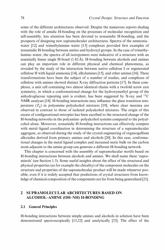
some of the different architectures observed. Despite the numerous reports dealing
with the role of amidic H-bonding on the processes of molecular recognition and
self-assembly, less attention has been devoted to nonamidic H-bonding, and the
prospects of designing new supramolecular architectures. Spectra of the ammonia±
water [12] and trimethylamine±water [13] complexes provided ®rst examples of
nonamidic H-bonding between amino and hydroxyl groups. In the case of trimethy-
lamine±water, the spectra of all isotopomers were indicative of a structure with an
essentially linear single H-bond (1.82 AÊ ). H-bonding between alcohols and amines
can play an important role in different physical and chemical phenomena, as
revealed by the study of the interaction between native cellulose I or regenerated
cellulose II with liquid ammonia [14], alkylamines [15], and other amines [16]. These
transformations have been the subject of a number of studies, and complexes of
cellulose with amines showed distinct X-ray diffraction patterns [17]. In these com-
plexes, a unit cell containing two almost identical chains with a twofold screw axis
symmetry, in which a conformational change for the hydroxymethyl group of the
anhydroglucose repeating unit is evident, has been suggested by X-ray and 13C
NMR analyses [18]. H-bonding interactions may in¯uence the glass transition tem-
perature (Tg) in polyamine±polyalcohol mixtures [19], where clear maxima are
observed in contrast to those of isolated polyalcohol mixtures. The origin of this
excess of con®gurational entropies has been ascribed to the structural change of the
H-bonding networks in the polyamine±polyalcohol systems compared to the polyal-
cohol alone. Moreover, nonamidic H-bonding interactions can effectively compete
with metal±ligand coordination in determining the structure of a supramolecular
aggregate, as observed during the study of the crystal engineering of organogallium
alkoxides derived from primary amines and alcohols [20]. In this case, conforma-
tional changes in the metal ligand complex and increased steric bulk on the carbon
atom adjacent to the amine group can generate a different H-bonding network.
This chapter is concerned with the assembly of supramolecular motifs based on
H-bonding interactions between alcohols and amines. We shall name these `supra-
minols' (see Section 1.3). Some useful insights about the effect of the structural and
physical properties (as for example the chirality) of the component molecules on the
structure and properties of the supramolecular product will be made whenever pos-
sible, even if it is widely accepted that predictions of crystal structures from know-
ledge of chemical composition of the components are far from being generalized [21].
2 SUPRAMOLECULAR ARCHITECTURES BASED ON
ALCOHOL±AMINE (OH±NH) H-BONDING
2.1 General Principles
H-bonding interactions between simple amines and alcohols in solution have been
demonstrated spectroscopically [13,22] and analytically [23]. The effect of the
78 Crystal Design: Structure and Function
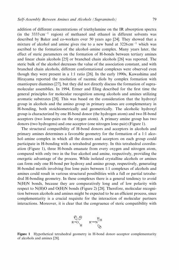
addition of different concentrations of triethylamine on the IR absorption spectra
(in the 3333 cmÿ1 region) of methanol and ethanol in different solvents was
described by Baker and co-workers over 50 years ago [24]. They showed that a
mixture of alcohol and amine gives rise to a new band at 3226 cmÿ1 which was
ascribed to the formation of the alcohol±amine complex. Many years later, the
effect of steric parameters on the formation of H-bonds between tertiary amines
and linear chain alcohols [25] or branched chain alcohols [26] was reported. The
steric bulk of the alcohol decreases the value of the association constant, and with
branched chain alcohols, different conformational complexes were observed even
though they were present in a 1:1 ratio [26]. In the early 1990s, Kawashima and
Hirayama reported the resolution of racemic diols by complex formation with
enantiopure diamines [27], but they did not directly discuss the formation of supra-
molecular assemblies. In 1994, Ermer and Eling described for the ®rst time the
general principles for molecular recognition among alcohols and amines utilizing
aromatic substrates [28]. This was based on the consideration that the hydroxyl
group in alcohols and the amino group in primary amines are complementary in
H-bonding, both stoichiometrically and geometrically. The alcoholic hydroxyl
group is characterized by one H-bond donor (the hydrogen atom) and two H-bond
acceptors (two lone-pairs on the oxygen atom). A primary amine group has two
donors (two hydrogens) and one acceptor (one nitrogen lone-pair) (Figure 1).
The structural compatibility of H-bond donors and acceptors in alcohols and
primary amines determines a favorable geometry for the formation of a 1:1 alco-
hol±amine complex in which all the donors and acceptors on each group could
participate in H-bonding with a tetrahedral geometry. In this tetrahedral coordin-
ation (Figure 1), three H-bonds emanate from every oxygen and nitrogen atom,
compared with only two in the free alcohol and amine, respectively, providing the
energetic advantage of the process. While isolated crystalline alcohols or amines
can form only one H-bond per hydroxy and amino group, respectively, generating
H-bonded motifs involving free lone pairs between 1:1 complexes of alcohols and
amines could result in various structural possibilities with a full or partial tetrahe-
dral H-bonding geometry. In these complexes there is a general tendency to avoid
N(H)N bonds, because they are comparatively long and of low polarity with
respect to N(H)O and O(H)N bonds (Figure 2) [28]. Therefore, molecular recogni-
tion between alcohols and amines might be expected to be an ef®cient process, since
complementarity is a crucial requisite for the interaction of molecular partners
interactions. Moreover, it is clear that the congruence of steric compatibility with
R OH
R' NHH
Figure 1 Hypothetical tetrahedral geometry in H-bond donor±acceptor complementarityof alcohols and amines [28].
Self-Assembly Between Amines and Alcohols (Supraminols) 79
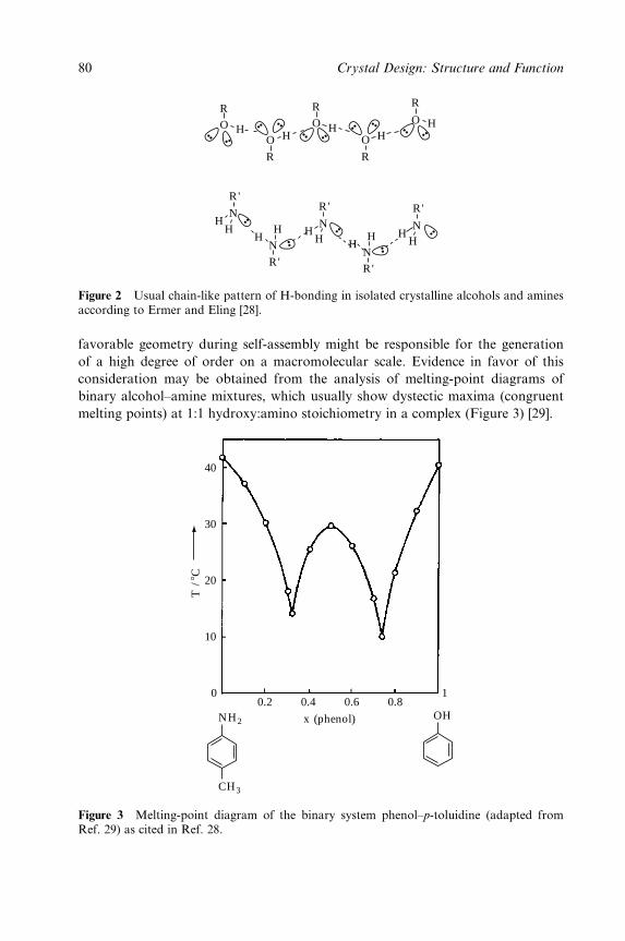
R
R
R'
R'
R
R
R
OO
O
OH
HH H
H HH H
HHHN
N
HH
HH
R'
R'
R'
O
N
N
N
Figure 2 Usual chain-like pattern of H-bonding in isolated crystalline alcohols and aminesaccording to Ermer and Eling [28].
favorable geometry during self-assembly might be responsible for the generation
of a high degree of order on a macromolecular scale. Evidence in favor of this
consideration may be obtained from the analysis of melting-point diagrams of
binary alcohol±amine mixtures, which usually show dystectic maxima (congruent
melting points) at 1:1 hydroxy:amino stoichiometry in a complex (Figure 3) [29].
0.2NH2 OH
CH3
0
10
20
30
40
10.4
x (phenol)
T /
8C
0.6 0.8
Figure 3 Melting-point diagram of the binary system phenol±p-toluidine (adapted fromRef. 29) as cited in Ref. 28.
80 Crystal Design: Structure and Function
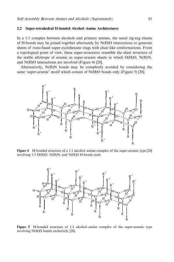
2.2 Super-tetrahedral H-bonded Alcohol±Amine Architectures
In a 1:1 complex between alcohols and primary amines, the usual zig-zag chains
of H-bonds may be joined together alternately by N(H)O interactions to generate
sheets of trans-fused super-cyclohexane rings with chair-like conformations. From
a topological point of view, these super-structures resemble the sheet structure of
the stable allotrope of arsenic as super-arsenic sheets in which O(H)O, N(H)N,
and N(H)O interactions are involved (Figure 4) [28].
Alternatively, N(H)N bonds may be completely avoided by considering the
same `super-arsenic' motif which consist of N(H)O bonds only (Figure 5) [28].
R
R
R
R
R
R
R
RR
,
R,
R,
R,
R,
R,
R,
R,
R,
R,
R,
R
R
R
N
N
N
N
N
N
N
N
N
N
N
HH H
H
HHH
H
H
H
HHH
HH
H
H
H
HHH
HHH
H
H
H
H
HH
H H
H
O
O
O
O
OO
O
O
O
O
O
Figure 4 H-bonded structure of a 1:1 alcohol±amine complex of the super-arsenic type [28]involving 1/3 O(H)O, N(H)N, and N(H)O H-bonds each.
R
R
R
R
R
R
R
R
R
R
R
R,
R,
R,
R,
R,
R,
R,
R,
R,
R,
R,
N
N
NN
N
N
N
N
NN
N
H
HH
HH
HH
H
H
H
H
H
H
H
H
H
H
HH
HH
HH
HH
HH
HH
HHH
H
O
O
O
O
O
O
O
O
O
O
O
Figure 5 H-bonded structure of 1:1 alcohol±amine complex of the super-arsenic typeinvolving N(H)O bonds exclusively [28].
Self-Assembly Between Amines and Alcohols (Supraminols) 81
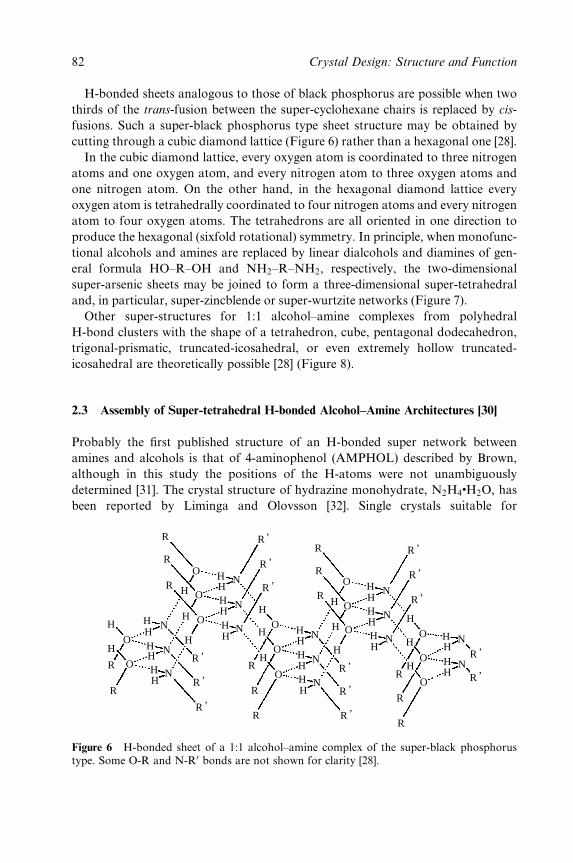
H-bonded sheets analogous to those of black phosphorus are possible when two
thirds of the trans-fusion between the super-cyclohexane chairs is replaced by cis-
fusions. Such a super-black phosphorus type sheet structure may be obtained by
cutting through a cubic diamond lattice (Figure 6) rather than a hexagonal one [28].
In the cubic diamond lattice, every oxygen atom is coordinated to three nitrogen
atoms and one oxygen atom, and every nitrogen atom to three oxygen atoms and
one nitrogen atom. On the other hand, in the hexagonal diamond lattice every
oxygen atom is tetrahedrally coordinated to four nitrogen atoms and every nitrogen
atom to four oxygen atoms. The tetrahedrons are all oriented in one direction to
produce the hexagonal (sixfold rotational) symmetry. In principle, when monofunc-
tional alcohols and amines are replaced by linear dialcohols and diamines of gen-
eral formula HO±R±OH and NH2±R±NH2, respectively, the two-dimensional
super-arsenic sheets may be joined to form a three-dimensional super-tetrahedral
and, in particular, super-zincblende or super-wurtzite networks (Figure 7).
Other super-structures for 1:1 alcohol±amine complexes from polyhedral
H-bond clusters with the shape of a tetrahedron, cube, pentagonal dodecahedron,
trigonal-prismatic, truncated-icosahedral, or even extremely hollow truncated-
icosahedral are theoretically possible [28] (Figure 8).
2.3 Assembly of Super-tetrahedral H-bonded Alcohol±Amine Architectures [30]
Probably the ®rst published structure of an H-bonded super network between
amines and alcohols is that of 4-aminophenol (AMPHOL) described by Brown,
although in this study the positions of the H-atoms were not unambiguously
determined [31]. The crystal structure of hydrazine monohydrate, N2H4�H2O, has
been reported by Liminga and Olovsson [32]. Single crystals suitable for
R
R
RO
O
O
H
H
H
HHHHHH
O
O
H
H
R
R
N
N
N HH H
H
H H
H H
R
R
R
O
OH
HH
N
NHH
H
HR
R
R
O
O
O
HH
H
H
HH N
N
N
H
O
HH
HHH
N
NR
,
R,
R,
R,
R,
R,R
R,
R,
R,
R,
R,
R,
R,
N
R
R
R
O
O
O
HHH N
N
NH
Figure 6 H-bonded sheet of a 1:1 alcohol±amine complex of the super-black phosphorustype. Some O-R and N-R0 bonds are not shown for clarity [28].
82 Crystal Design: Structure and Function
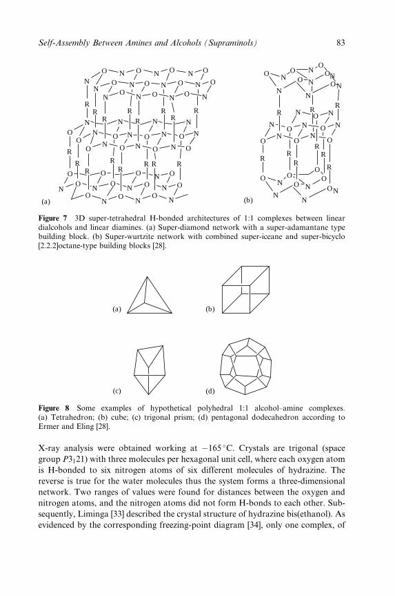
N
NN
N N
NNN
N N N N
N
N
N
NN
N
N
N N
N
N
N
N
N
N N OOO
OO
RR
RR
RR R
R
RRRR
R
RR
R
O O
OO
O
O
O
OO
O
O
O
O
O O O
O
O
OO
OOO
O
O
ON
N
N
R RR
RRR
RR
R
O OO
O
OO
O
O
OO
OOO
OOO
O
O
N
N
N
N
N
N
N
NN
NN
N
N
N
N
N
NN
N
(b)(a)
Figure 7 3D super-tetrahedral H-bonded architectures of 1:1 complexes between lineardialcohols and linear diamines. (a) Super-diamond network with a super-adamantane typebuilding block. (b) Super-wurtzite network with combined super-iceane and super-bicyclo[2.2.2]octane-type building blocks [28].
(a) (b)
(c) (d)
Figure 8 Some examples of hypothetical polyhedral 1:1 alcohol±amine complexes.(a) Tetrahedron; (b) cube; (c) trigonal prism; (d) pentagonal dodecahedron according toErmer and Eling [28].
X-ray analysis were obtained working at ÿ165 �C. Crystals are trigonal (space
group P3121) with three molecules per hexagonal unit cell, where each oxygen atom
is H-bonded to six nitrogen atoms of six different molecules of hydrazine. The
reverse is true for the water molecules thus the system forms a three-dimensional
network. Two ranges of values were found for distances between the oxygen and
nitrogen atoms, and the nitrogen atoms did not form H-bonds to each other. Sub-
sequently, Liminga [33] described the crystal structure of hydrazine bis(ethanol). As
evidenced by the corresponding freezing-point diagram [34], only one complex, of
Self-Assembly Between Amines and Alcohols (Supraminols) 83
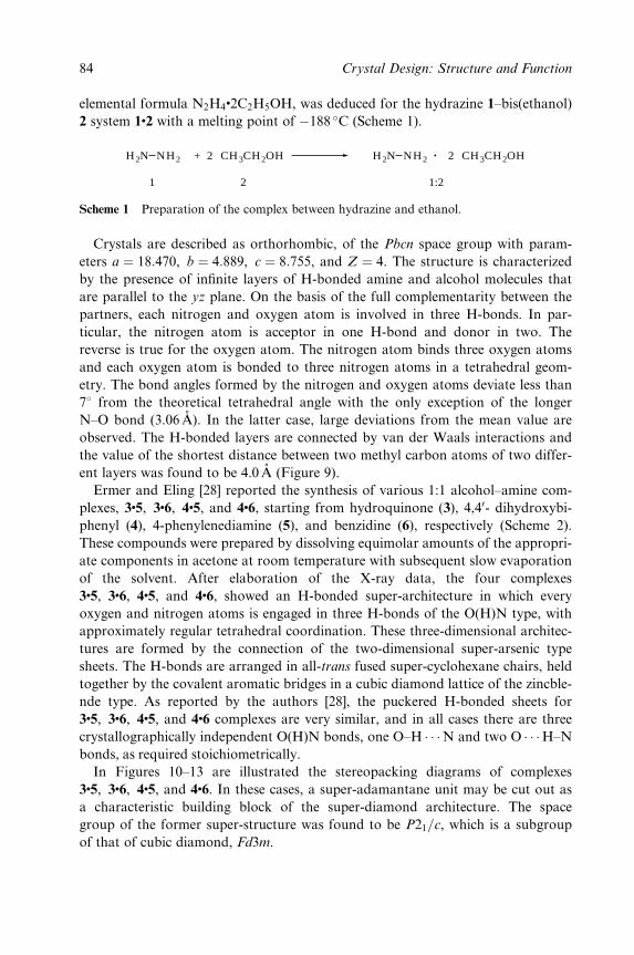
elemental formula N2H4�2C2H5OH, was deduced for the hydrazine 1±bis(ethanol)
2 system 1�2 with a melting point of ÿ188 �C (Scheme 1).
H2N NH2 2 CH3CH2OH+ H2N NH2 2 CH3CH2OH
1 2 1:2
Scheme 1 Preparation of the complex between hydrazine and ethanol.
Crystals are described as orthorhombic, of the Pbcn space group with param-
eters a � 18:470, b � 4:889, c � 8:755, and Z � 4. The structure is characterized
by the presence of in®nite layers of H-bonded amine and alcohol molecules that
are parallel to the yz plane. On the basis of the full complementarity between the
partners, each nitrogen and oxygen atom is involved in three H-bonds. In par-
ticular, the nitrogen atom is acceptor in one H-bond and donor in two. The
reverse is true for the oxygen atom. The nitrogen atom binds three oxygen atoms
and each oxygen atom is bonded to three nitrogen atoms in a tetrahedral geom-
etry. The bond angles formed by the nitrogen and oxygen atoms deviate less than
78 from the theoretical tetrahedral angle with the only exception of the longer
N±O bond (3.06 AÊ ). In the latter case, large deviations from the mean value are
observed. The H-bonded layers are connected by van der Waals interactions and
the value of the shortest distance between two methyl carbon atoms of two differ-
ent layers was found to be 4.0 AÊ (Figure 9).
Ermer and Eling [28] reported the synthesis of various 1:1 alcohol±amine com-
plexes, 3�5, 3�6, 4�5, and 4�6, starting from hydroquinone (3), 4,40- dihydroxybi-
phenyl (4), 4-phenylenediamine (5), and benzidine (6), respectively (Scheme 2).
These compounds were prepared by dissolving equimolar amounts of the appropri-
ate components in acetone at room temperature with subsequent slow evaporation
of the solvent. After elaboration of the X-ray data, the four complexes
3�5, 3�6, 4�5, and 4�6, showed an H-bonded super-architecture in which every
oxygen and nitrogen atoms is engaged in three H-bonds of the O(H)N type, with
approximately regular tetrahedral coordination. These three-dimensional architec-
tures are formed by the connection of the two-dimensional super-arsenic type
sheets. The H-bonds are arranged in all-trans fused super-cyclohexane chairs, held
together by the covalent aromatic bridges in a cubic diamond lattice of the zincble-
nde type. As reported by the authors [28], the puckered H-bonded sheets for
3�5, 3�6, 4�5, and 4�6 complexes are very similar, and in all cases there are three
crystallographically independent O(H)N bonds, one O±H � � �N and two O � � �H±N
bonds, as required stoichiometrically.
In Figures 10±13 are illustrated the stereopacking diagrams of complexes
3�5, 3�6, 4�5, and 4�6. In these cases, a super-adamantane unit may be cut out as
a characteristic building block of the super-diamond architecture. The space
group of the former super-structure was found to be P21=c, which is a subgroup
of that of cubic diamond, Fd3m.
84 Crystal Design: Structure and Function
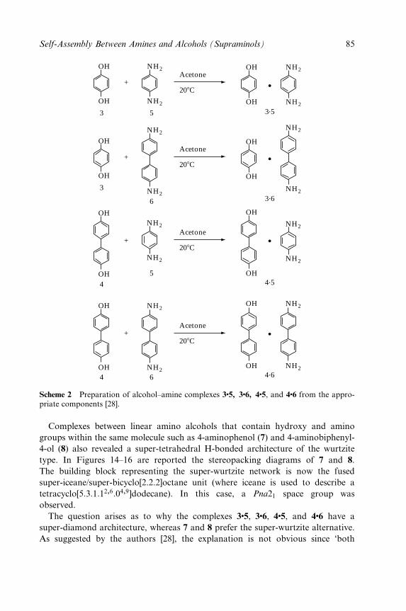
208C
Acetone+
3 5 3.5
OH
OH NH2
NH2 OH
OH NH2
NH2
+
3.6
3
OH
OH
NH2
NH2
NH2
NH2
OH
OH
208C
Acetone
6
+
4.54
5
NH2
NH2
NH2
NH2
OH
OH
OH
OH
208C
Acetone
+
4.64 6
OH
OH
OH
OH
NH2
NH2
NH2
NH2
208C
Acetone
Scheme 2 Preparation of alcohol±amine complexes 3�5, 3�6, 4�5, and 4�6 from the appro-priate components [28].
Complexes between linear amino alcohols that contain hydroxy and amino
groups within the same molecule such as 4-aminophenol (7) and 4-aminobiphenyl-
4-ol (8) also revealed a super-tetrahedral H-bonded architecture of the wurtzite
type. In Figures 14±16 are reported the stereopacking diagrams of 7 and 8.
The building block representing the super-wurtzite network is now the fused
super-iceane/super-bicyclo[2.2.2]octane unit (where iceane is used to describe a
tetracyclo[5:3:1:12,6:04,9]dodecane). In this case, a Pna21 space group was
observed.
The question arises as to why the complexes 3�5, 3�6, 4�5, and 4�6 have a
super-diamond architecture, whereas 7 and 8 prefer the super-wurtzite alternative.
As suggested by the authors [28], the explanation is not obvious since `both
Self-Assembly Between Amines and Alcohols (Supraminols) 85
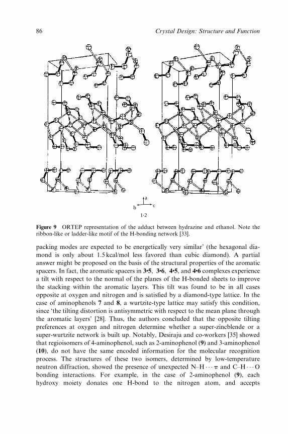
a
b c
1.2
Figure 9 ORTEP representation of the adduct between hydrazine and ethanol. Note theribbon-like or ladder-like motif of the H-bonding network [33].
packing modes are expected to be energetically very similar' (the hexagonal dia-
mond is only about 1.5 kcal/mol less favored than cubic diamond). A partial
answer might be proposed on the basis of the structural properties of the aromatic
spacers. In fact, the aromatic spacers in 3�5, 3�6, 4�5, and 4�6 complexes experience
a tilt with respect to the normal of the planes of the H-bonded sheets to improve
the stacking within the aromatic layers. This tilt was found to be in all cases
opposite at oxygen and nitrogen and is satis®ed by a diamond-type lattice. In the
case of aminophenols 7 and 8, a wurtzite-type lattice may satisfy this condition,
since `the tilting distortion is antisymmetric with respect to the mean plane through
the aromatic layers' [28]. Thus, the authors concluded that the opposite tilting
preferences at oxygen and nitrogen determine whether a super-zincblende or a
super-wurtzite network is built up. Notably, Desiraju and co-workers [35] showed
that regioisomers of 4-aminophenol, such as 2-aminophenol (9) and 3-aminophenol
(10), do not have the same encoded information for the molecular recognition
process. The structures of these two isomers, determined by low-temperature
neutron diffraction, showed the presence of unexpected N±H � � �p and C±H � � �Obonding interactions. For example, in the case of 2-aminophenol (9), each
hydroxy moiety donates one H-bond to the nitrogen atom, and accepts
86 Crystal Design: Structure and Function
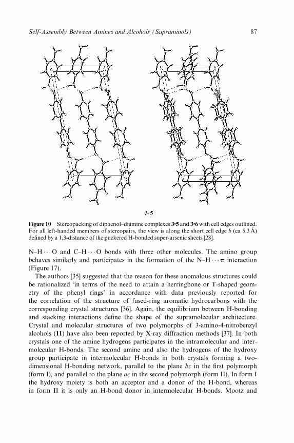
Figure 10 Stereopacking of diphenol±diamine complexes 3�5 and 3�6 with cell edges outlined.For all left-handed members of stereopairs, the view is along the short cell edge b (ca 5.3 AÊ )de®ned by a 1,3-distance of the puckered H-bonded super-arsenic sheets [28].
N±H � � �O and C±H � � �O bonds with three other molecules. The amino group
behaves similarly and participates in the formation of the N±H � � �p interaction
(Figure 17).
The authors [35] suggested that the reason for these anomalous structures could
be rationalized `in terms of the need to attain a herringbone or T-shaped geom-
etry of the phenyl rings' in accordance with data previously reported for
the correlation of the structure of fused-ring aromatic hydrocarbons with the
corresponding crystal structures [36]. Again, the equilibrium between H-bonding
and stacking interactions de®ne the shape of the supramolecular architecture.
Crystal and molecular structures of two polymorphs of 3-amino-4-nitrobenzyl
alcohols (11) have also been reported by X-ray diffraction methods [37]. In both
crystals one of the amine hydrogens participates in the intramolecular and inter-
molecular H-bonds. The second amine and also the hydrogens of the hydroxy
group participate in intermolecular H-bonds in both crystals forming a two-
dimensional H-bonding network, parallel to the plane bc in the ®rst polymorph
(form I), and parallel to the plane ac in the second polymorph (form II). In form I
the hydroxy moiety is both an acceptor and a donor of the H-bond, whereas
in form II it is only an H-bond donor in intermolecular H-bonds. Mootz and
Self-Assembly Between Amines and Alcohols (Supraminols) 87
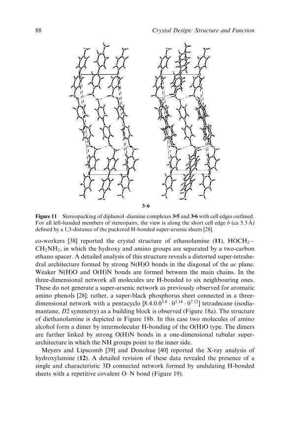
Figure 11 Stereopacking of diphenol±diamine complexes 3�5 and 3�6 with cell edges outlined.For all left-handed members of stereopairs, the view is along the short cell edge b (ca 5.3 AÊ )de®ned by a 1,3-distance of the puckered H-bonded super-arsenic sheets [28].
co-workers [38] reported the crystal structure of ethanolamine (11), HOCH2ÿCH2NH2, in which the hydroxy and amino groups are separated by a two-carbon
ethano spacer. A detailed analysis of this structure reveals a distorted super-tetrahe-
dral architecture formed by strong N(H)O bonds in the diagonal of the ac plane.
Weaker N(H)O and O(H)N bonds are formed between the main chains. In the
three-dimensional network all molecules are H-bonded to six neighbouring ones.
These do not generate a super-arsenic network as previously observed for aromatic
amino phenols [28]; rather, a super-black phosphorus sheet connected in a three-
dimensional network with a pentacyclo [8:4:0:03:8 � 05:14 � 07:12] tetradecane (isodia-
mantane, D2 symmetry) as a building block is observed (Figure 18a). The structure
of diethanolamine is depicted in Figure 18b. In this case two molecules of amino
alcohol form a dimer by intermolecular H-bonding of the O(H)O type. The dimers
are further linked by strong O(H)N bonds in a one-dimensional tubular super-
architecture in which the NH groups point to the inner side.
Meyers and Lipscomb [39] and Donohue [40] reported the X-ray analysis of
hydroxylamine (12). A detailed revision of these data revealed the presence of a
single and characteristic 3D connected network formed by undulating H-bonded
sheets with a repetitive covalent O±N bond (Figure 19).
AQ1
88 Crystal Design: Structure and Function
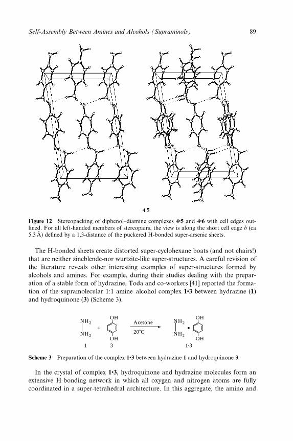
Figure 12 Stereopacking of diphenol±diamine complexes 4�5 and 4�6 with cell edges out-lined. For all left-handed members of stereopairs, the view is along the short cell edge b (ca5.3 AÊ ) de®ned by a 1,3-distance of the puckered H-bonded super-arsenic sheets.
The H-bonded sheets create distorted super-cyclohexane boats (and not chairs!)
that are neither zincblende-nor wurtzite-like super-structures. A careful revision of
the literature reveals other interesting examples of super-structures formed by
alcohols and amines. For example, during their studies dealing with the prepar-
ation of a stable form of hydrazine, Toda and co-workers [41] reported the forma-
tion of the supramolecular 1:1 amine±alcohol complex 1�3 between hydrazine (1)
and hydroquinone (3) (Scheme 3).
OH
OH
OH
OH
+
1 3 1.3
NH2
NH2
NH2
NH2Acetone
208C
Scheme 3 Preparation of the complex 1�3 between hydrazine 1 and hydroquinone 3.
In the crystal of complex 1�3, hydroquinone and hydrazine molecules form an
extensive H-bonding network in which all oxygen and nitrogen atoms are fully
coordinated in a super-tetrahedral architecture. In this aggregate, the amino and
Self-Assembly Between Amines and Alcohols (Supraminols) 89
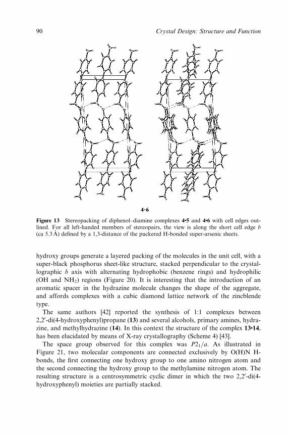
Figure 13 Stereopacking of diphenol±diamine complexes 4�5 and 4�6 with cell edges out-lined. For all left-handed members of stereopairs, the view is along the short cell edge b
(ca 5.3 AÊ ) de®ned by a 1,3-distance of the puckered H-bonded super-arsenic sheets.
hydroxy groups generate a layered packing of the molecules in the unit cell, with a
super-black phosphorus sheet-like structure, stacked perpendicular to the crystal-
lographic b axis with alternating hydrophobic (benzene rings) and hydrophilic
(OH and NH2) regions (Figure 20). It is interesting that the introduction of an
aromatic spacer in the hydrazine molecule changes the shape of the aggregate,
and affords complexes with a cubic diamond lattice network of the zincblende
type.
The same authors [42] reported the synthesis of 1:1 complexes between
2,20-di(4-hydroxyphenyl)propane (13) and several alcohols, primary amines, hydra-
zine, and methylhydrazine (14). In this context the structure of the complex 13�14,
has been elucidated by means of X-ray crystallography (Scheme 4) [43].
The space group observed for this complex was P21=a. As illustrated in
Figure 21, two molecular components are connected exclusively by O(H)N H-
bonds, the ®rst connecting one hydroxy group to one amino nitrogen atom and
the second connecting the hydroxy group to the methylamine nitrogen atom. The
resulting structure is a centrosymmetric cyclic dimer in which the two 2,20-di(4-
hydroxyphenyl) moieties are partially stacked.
90 Crystal Design: Structure and Function
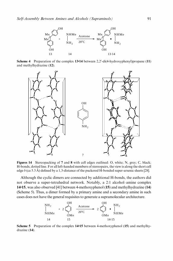
13 14 13.14OH
Me
Me
OH
OH
Me
Me
OH
+NH2
NHMe
NH2
NHMeAcetone
208C
Scheme 4 Preparation of the complex 13�14 between 2,20-di(4-hydroxyphenyl)propane (11)and methylhydrazine (12).
OH
NH2
7
Figures 14 Stereopacking of 7 and 8 with cell edges outlined: O, white; N, grey; C, black;H-bonds, dotted line. For all left-handed members of stereopairs, the view is along the short celledge b (ca 5.3 AÊ ) de®ned by a 1,3-distance of the puckered H-bonded super-arsenic sheets [28].
Although the cyclic dimers are connected by additional H-bonds, the authors did
not observe a super-tetrahedral network. Notably, a 2:1 alcohol±amine complex
14�15, was also observed [41] between 4-methoxyphenol (15) and methylhydrazine (14)
(Scheme 5). Thus, a dimer formed by a primary amine and a secondary amine in such
cases does not have the general requisites to generate a supramolecular architecture.
NH2
NHMe
NH2
NHMe
Acetone
208COMe
OH
2
OMe
OH
2
14 15 14.15
+
Scheme 5 Preparation of the complex 14�15 between 4-methoxyphenol (15) and methylhy-drazine (14).
Self-Assembly Between Amines and Alcohols (Supraminols) 91
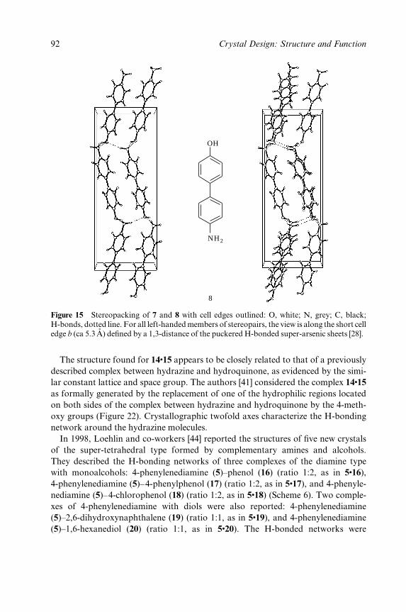
OH
NH2
8
Figure 15 Stereopacking of 7 and 8 with cell edges outlined: O, white; N, grey; C, black;H-bonds, dotted line. For all left-handed members of stereopairs, the view is along the short celledge b (ca 5.3AÊ ) de®ned by a 1,3-distance of the puckered H-bonded super-arsenic sheets [28].
The structure found for 14�15 appears to be closely related to that of a previously
described complex between hydrazine and hydroquinone, as evidenced by the simi-
lar constant lattice and space group. The authors [41] considered the complex 14�15
as formally generated by the replacement of one of the hydrophilic regions located
on both sides of the complex between hydrazine and hydroquinone by the 4-meth-
oxy groups (Figure 22). Crystallographic twofold axes characterize the H-bonding
network around the hydrazine molecules.
In 1998, Loehlin and co-workers [44] reported the structures of ®ve new crystals
of the super-tetrahedral type formed by complementary amines and alcohols.
They described the H-bonding networks of three complexes of the diamine type
with monoalcohols: 4-phenylenediamine (5)±phenol (16) (ratio 1:2, as in 5�16),
4-phenylenediamine (5)±4-phenylphenol (17) (ratio 1:2, as in 5�17), and 4-phenyle-
nediamine (5)±4-chlorophenol (18) (ratio 1:2, as in 5�18) (Scheme 6). Two comple-
xes of 4-phenylenediamine with diols were also reported: 4-phenylenediamine
(5)±2,6-dihydroxynaphthalene (19) (ratio 1:1, as in 5�19), and 4-phenylenediamine
(5)±1,6-hexanediol (20) (ratio 1:1, as in 5�20). The H-bonded networks were
92 Crystal Design: Structure and Function
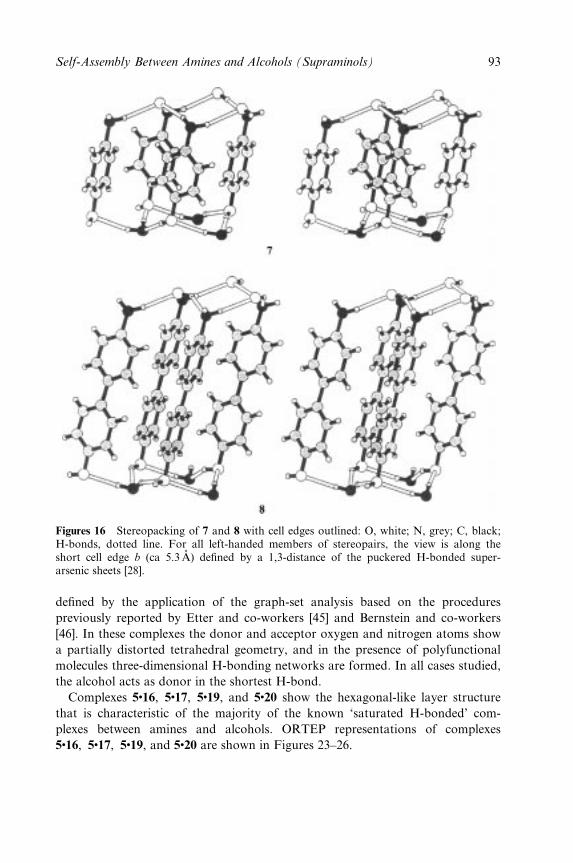
Figures 16 Stereopacking of 7 and 8 with cell edges outlined: O, white; N, grey; C, black;H-bonds, dotted line. For all left-handed members of stereopairs, the view is along theshort cell edge b (ca 5.3 AÊ ) de®ned by a 1,3-distance of the puckered H-bonded super-arsenic sheets [28].
de®ned by the application of the graph-set analysis based on the procedures
previously reported by Etter and co-workers [45] and Bernstein and co-workers
[46]. In these complexes the donor and acceptor oxygen and nitrogen atoms show
a partially distorted tetrahedral geometry, and in the presence of polyfunctional
molecules three-dimensional H-bonding networks are formed. In all cases studied,
the alcohol acts as donor in the shortest H-bond.
Complexes 5�16, 5�17, 5�19, and 5�20 show the hexagonal-like layer structure
that is characteristic of the majority of the known `saturated H-bonded' com-
plexes between amines and alcohols. ORTEP representations of complexes
5�16, 5�17, 5�19, and 5�20 are shown in Figures 23±26.
Self-Assembly Between Amines and Alcohols (Supraminols) 93
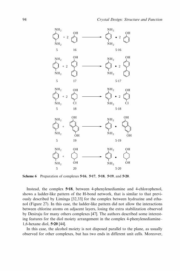
5 16 5.16
NH2
NH2
NH2
NH2
OH+ 2
OH2
17 5.175
NH2
NH2
NH2
NH2
OH OH
+ 2 2
5.18185
NH2
NH2
NH2
NH2
OH
CI
OH
CI
+ 2 2
5.20205
OH
OH
OH
OH
NH2
NH2
NH2
NH2
+
5.19195
NH2
NH2
NH2
NH2
+
OH
OH
OH
OH
Scheme 6 Preparation of complexes 5�16, 5�17, 5�18, 5�19, and 5�20.
Instead, the complex 5�18, between 4-phenylenediamine and 4-chlorophenol,
shows a ladder-like pattern of the H-bond network, that is similar to that previ-
ously described by Liminga [32,33] for the complex between hydrazine and etha-
nol (Figure 27). In this case, the ladder-like pattern did not allow the interactions
between chlorine atoms on adjacent layers, losing the extra stabilization observed
by Desiraju for many others complexes [47]. The authors described some interest-
ing features for the diol moiety arrangement in the complex 4-phenylenediamine±
1,6-hexane diol, 5�20 [44].
In this case, the alcohol moiety is not disposed parallel to the plane, as usually
observed for other complexes, but has two ends in different unit cells. Moreover,
94 Crystal Design: Structure and Function
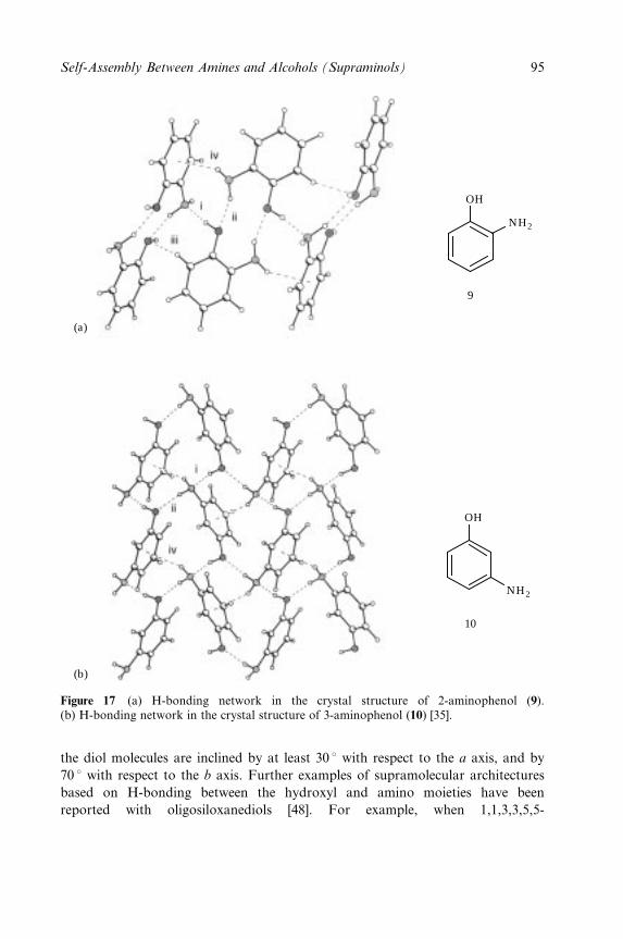
(a)
(b)
OH
NH2
OH
NH2
9
10
Figure 17 (a) H-bonding network in the crystal structure of 2-aminophenol (9).(b) H-bonding network in the crystal structure of 3-aminophenol (10) [35].
the diol molecules are inclined by at least 30 8 with respect to the a axis, and by
70 8 with respect to the b axis. Further examples of supramolecular architectures
based on H-bonding between the hydroxyl and amino moieties have been
reported with oligosiloxanediols [48]. For example, when 1,1,3,3,5,5-
Self-Assembly Between Amines and Alcohols (Supraminols) 95
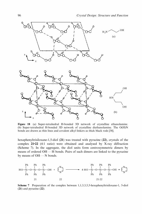
H2NOH
HN
OH
OH
(a)
(b)
x
z
x
z
Figure 18 (a) Super-tetrahedral H-bonded 3D network of crystalline ethanolamine.(b) Super-tetrahedral H-bonded 3D network of crystalline diethanolamine. The O(H)Nbonds are drawn as thin lines and covalent alkyl linkers as thick black rods [38].
hexaphenyltrisiloxane-1,5-diol (21) was treated with pyrazine (22), crystals of the
complex 21�22 (4:1 ratio) were obtained and analysed by X-ray diffraction
(Scheme 7). In the aggregate, the diol units form centrosymmetric dimers by
means of ordered OH � � �H bonds. Pairs of such dimers are linked to the pyrazine
by means of OH � � �N bonds.
21 22 21.22
Ph
Ph Ph Ph
Ph Ph
HO OHSi Si OO Si
Ph
Ph Ph Ph
Ph Ph
4 HO OHSi Si OO Si+N
N
N
N
Scheme 7 Preparation of the complex between 1,1,3,3,5,5-hexaphenyltrisiloxane-1, 5-diol(21) and pyrazine (22).
96 Crystal Design: Structure and Function
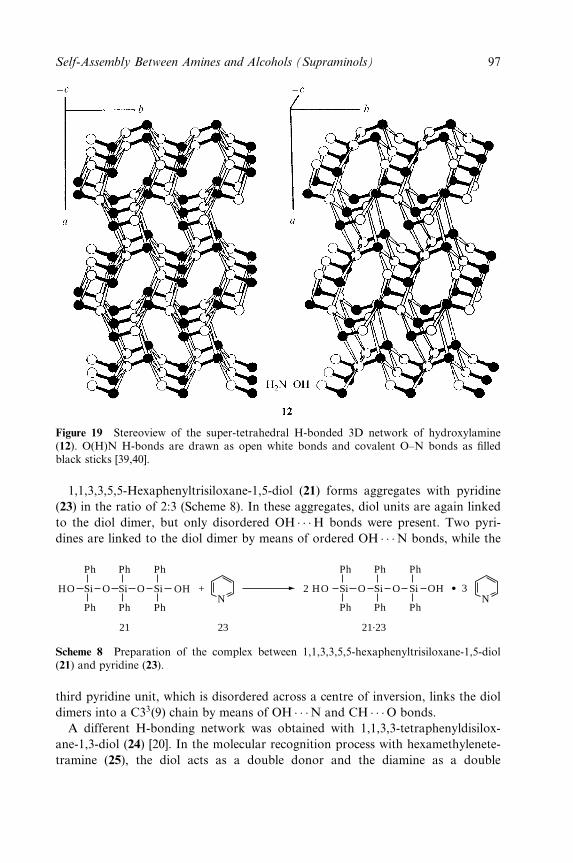
Figure 19 Stereoview of the super-tetrahedral H-bonded 3D network of hydroxylamine(12). O(H)N H-bonds are drawn as open white bonds and covalent O±N bonds as ®lledblack sticks [39,40].
1,1,3,3,5,5-Hexaphenyltrisiloxane-1,5-diol (21) forms aggregates with pyridine
(23) in the ratio of 2:3 (Scheme 8). In these aggregates, diol units are again linked
to the diol dimer, but only disordered OH � � �H bonds were present. Two pyri-
dines are linked to the diol dimer by means of ordered OH � � �N bonds, while the
NN
21 23 21.23
Ph
Ph Ph Ph
Ph Ph
HO OHSi Si OO Si
Ph
Ph Ph Ph
Ph Ph
2 HO OHSi Si OO Si+ 3
Scheme 8 Preparation of the complex between 1,1,3,3,5,5-hexaphenyltrisiloxane-1,5-diol(21) and pyridine (23).
third pyridine unit, which is disordered across a centre of inversion, links the diol
dimers into a C33(9) chain by means of OH � � �N and CH � � �O bonds.
A different H-bonding network was obtained with 1,1,3,3-tetraphenyldisilox-
ane-1,3-diol (24) [20]. In the molecular recognition process with hexamethylenete-
tramine (25), the diol acts as a double donor and the diamine as a double
Self-Assembly Between Amines and Alcohols (Supraminols) 97
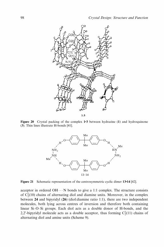
Figure 20 Crystal packing of the complex 1�3 between hydrazine (1) and hydroquinone(3). Thin lines illustrate H-bonds [41].
Me
NH2
HNMe
HO
HO
Me
Me
Me
OH
NH2
NHMe
HO
13.14
Figure 21 Schematic representation of the centrosymmetric cyclic dimer 13�14 [42].
acceptor in ordered OH � � �N bonds to give a 1:1 complex. The structure consists
of C22(10) chains of alternating diol and diamine units. Moreover, in the complex
between 24 and bipyridyl (26) (diol:diamine ratio 1:1), there are two independent
molecules, both lying across centres of inversion and therefore both containing
linear Si±O±Si groups. Each diol acts as a double donor of H-bonds, and the
2,20-bipyridyl molecule acts as a double acceptor, thus forming C22(11) chains of
alternating diol and amine units (Scheme 9).
98 Crystal Design: Structure and Function
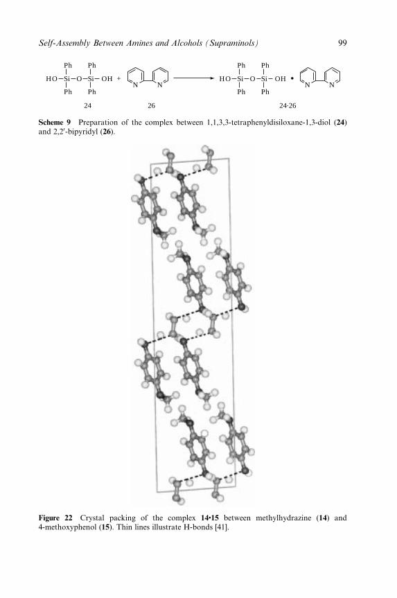
24 26 24.26
+N N N N
Ph
Ph Ph
Ph
HO Si Si OHO
Ph
Ph Ph
Ph
HO Si Si OHO
Scheme 9 Preparation of the complex between 1,1,3,3-tetraphenyldisiloxane-1,3-diol (24)and 2,20-bipyridyl (26).
Figure 22 Crystal packing of the complex 14�15 between methylhydrazine (14) and4-methoxyphenol (15). Thin lines illustrate H-bonds [41].
Self-Assembly Between Amines and Alcohols (Supraminols) 99
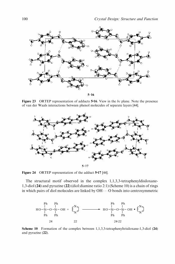
Figure 23 ORTEP representation of adducts 5�16. View in the bc plane. Note the presenceof van der Waals interactions between phenol molecules of separate layers [44].
Figure 24 ORTEP representation of the adduct 5�17 [44].
The structural motif observed in the complex 1,1,3,3-tetraphenyldisiloxane-
1,3-diol (24) and pyrazine (22) (diol:diamine ratio 2:1) (Scheme 10) is a chain of rings
in which pairs of diol molecules are linked by OH � � �O bonds into centrosymmetric
24 22 24.22
+N
N
N
NPh
Ph Ph
Ph
HO Si Si OHO
Ph
Ph Ph
Ph
HO Si Si OHO
Scheme 10 Formation of the complex between 1,1,3,3-tetraphenyltrisiloxane-1,3-diol (24)and pyrazine (22).
100 Crystal Design: Structure and Function

Figure 25 ORTEP representation of the adduct 5�19. The diol moieties are approximatelyparallel to the projection [44].
Figure 26 ORTEP representation of the adduct 5�20. Note that the alcohol moiety is notdisposed parallel to the plane and has two ends in different unit cells [44].
R22(12) dimers. These dimers are further linked into C2
2(13) chains by means of
OH � � �N bonds to the pyrazine units.
3 HELICAL H-BONDED MOLECULAR NETWORKS FORMED
BY ACHIRAL ALCOHOLS AND ACHIRAL AMINES
Hosseini and co-workers [49] described the synthesis of an in®nite single strand
helical supramolecular network 27�4 by mixing equimolar amounts of the calix[4]-
arene derivative 27, bearing four pyridine groups as H-bond acceptors, with
Self-Assembly Between Amines and Alcohols (Supraminols) 101
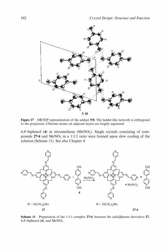
Figure 27 ORTEP representation of the adduct 5�8. The ladder-like network is orthogonalto the projection. Chlorine atoms on adjacent layers are largely separated.
4,40-biphenol (4) in nitromethane (MeNO2). Single crystals consisting of com-
pounds 27�4 and MeNO2 in a 1:1:1 ratio were formed upon slow cooling of the
solution (Scheme 11). See also Chapter 4.
+
OH
OH
OH
OH
N
N
NN
NN
N
RRRR
N
N
N
NN
NN
N
RRRR
N
R= O(CH2)2Me R= O(CH2)2Me
27
4
MeNO2
MeNO2
27.4
Scheme 11 Preparation of the 1:1:1 complex 27�4, between the calix[4]arene derivative 27,4,40-biphenol (4), and MeNO2.
102 Crystal Design: Structure and Function
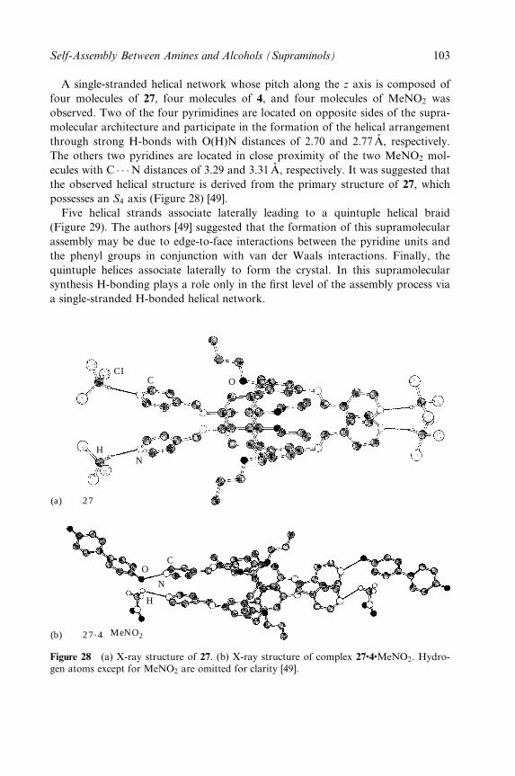
A single-stranded helical network whose pitch along the z axis is composed of
four molecules of 27, four molecules of 4, and four molecules of MeNO2 was
observed. Two of the four pyrimidines are located on opposite sides of the supra-
molecular architecture and participate in the formation of the helical arrangement
through strong H-bonds with O(H)N distances of 2.70 and 2.77AÊ , respectively.
The others two pyridines are located in close proximity of the two MeNO2 mol-
ecules with C � � �N distances of 3.29 and 3.31 AÊ , respectively. It was suggested that
the observed helical structure is derived from the primary structure of 27, which
possesses an S4 axis (Figure 28) [49].
Five helical strands associate laterally leading to a quintuple helical braid
(Figure 29). The authors [49] suggested that the formation of this supramolecular
assembly may be due to edge-to-face interactions between the pyridine units and
the phenyl groups in conjunction with van der Waals interactions. Finally, the
quintuple helices associate laterally to form the crystal. In this supramolecular
synthesis H-bonding plays a role only in the ®rst level of the assembly process via
a single-stranded H-bonded helical network.
(a)
(b)
OCCI
H
H
OC
N
N
27
27.4 MeNO2
Figure 28 (a) X-ray structure of 27. (b) X-ray structure of complex 27�4�MeNO2. Hydro-gen atoms except for MeNO2 are omitted for clarity [49].
Self-Assembly Between Amines and Alcohols (Supraminols) 103
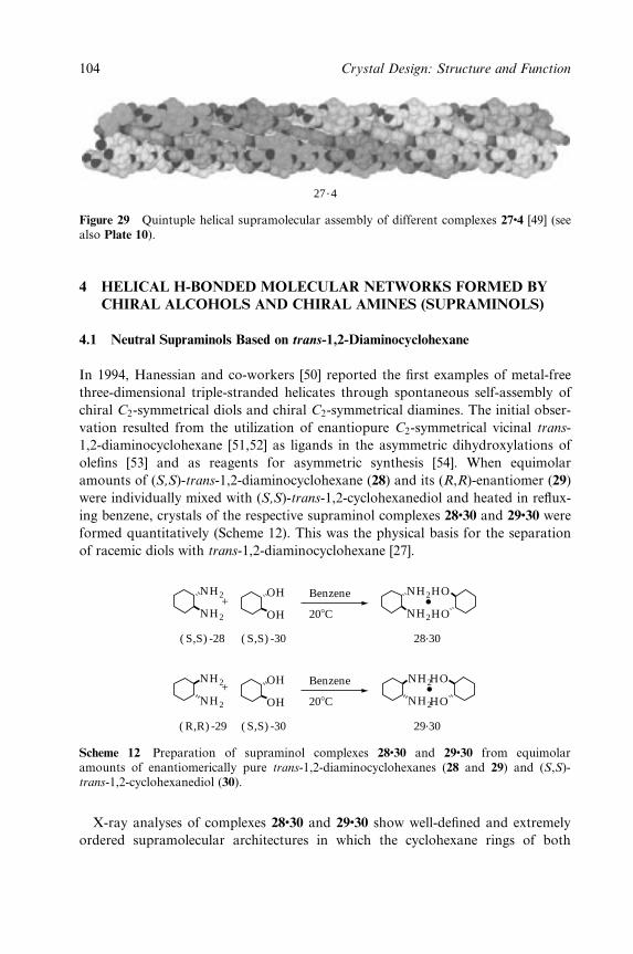
27.4
Figure 29 Quintuple helical supramolecular assembly of different complexes 27�4 [49] (seealso Plate 10).
4 HELICAL H-BONDED MOLECULAR NETWORKS FORMED BY
CHIRAL ALCOHOLS AND CHIRAL AMINES (SUPRAMINOLS)
4.1 Neutral Supraminols Based on trans-1,2-Diaminocyclohexane
In 1994, Hanessian and co-workers [50] reported the ®rst examples of metal-free
three-dimensional triple-stranded helicates through spontaneous self-assembly of
chiral C2-symmetrical diols and chiral C2-symmetrical diamines. The initial obser-
vation resulted from the utilization of enantiopure C2-symmetrical vicinal trans-
1,2-diaminocyclohexane [51,52] as ligands in the asymmetric dihydroxylations of
ole®ns [53] and as reagents for asymmetric synthesis [54]. When equimolar
amounts of (S,S)-trans-1,2-diaminocyclohexane (28) and its (R,R)-enantiomer (29)
were individually mixed with (S,S)-trans-1,2-cyclohexanediol and heated in re¯ux-
ing benzene, crystals of the respective supraminol complexes 28�30 and 29�30 were
formed quantitatively (Scheme 12). This was the physical basis for the separation
of racemic diols with trans-1,2-diaminocyclohexane [27].
( S,S) -30 28.30
29.30
( S,S) -28
( S,S) -30( R,R) -29
208C
Benzene
208C
Benzene
NH2
NH2
+OH
OH
NH2
NH2
+OH
OH
NH2
NH2HO
HO
NH2
NH2HO
HO
Scheme 12 Preparation of supraminol complexes 28�30 and 29�30 from equimolaramounts of enantiomerically pure trans-1,2-diaminocyclohexanes (28 and 29) and (S,S)-trans-1,2-cyclohexanediol (30).
X-ray analyses of complexes 28�30 and 29�30 show well-de®ned and extremely
ordered supramolecular architectures in which the cyclohexane rings of both
104 Crystal Design: Structure and Function
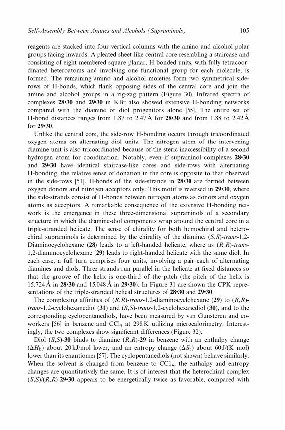
reagents are stacked into four vertical columns with the amino and alcohol polar
groups facing inwards. A pleated sheet-like central core resembling a staircase and
consisting of eight-membered square-planar, H-bonded units, with fully tetracoor-
dinated heteroatoms and involving one functional group for each molecule, is
formed. The remaining amino and alcohol moieties form two symmetrical side-
rows of H-bonds, which ¯ank opposing sides of the central core and join the
amine and alcohol groups in a zig-zag pattern (Figure 30). Infrared spectra of
complexes 28�30 and 29�30 in KBr also showed extensive H-bonding networks
compared with the diamine or diol progenitors alone [55]. The entire set of
H-bond distances ranges from 1.87 to 2.47AÊ for 28�30 and from 1.88 to 2.42AÊ
for 29�30.
Unlike the central core, the side-row H-bonding occurs through tricoordinated
oxygen atoms on alternating diol units. The nitrogen atom of the intervening
diamine unit is also tricoordinated because of the steric inaccessibility of a second
hydrogen atom for coordination. Notably, even if supraminol complexes 28�30
and 29�30 have identical staircase-like cores and side-rows with alternating
H-bonding, the relative sense of donation in the core is opposite to that observed
in the side-rows [51]. H-bonds of the side-strands in 28�30 are formed between
oxygen donors and nitrogen acceptors only. This motif is reversed in 29�30, where
the side-strands consist of H-bonds between nitrogen atoms as donors and oxygen
atoms as acceptors. A remarkable consequence of the extensive H-bonding net-
work is the emergence in these three-dimensional supraminols of a secondary
structure in which the diamine-diol components wrap around the central core in a
triple-stranded helicate. The sense of chirality for both homochiral and hetero-
chiral supraminols is determined by the chirality of the diamine. (S,S)-trans-1,2-
Diaminocyclohexane (28) leads to a left-handed helicate, where as (R,R)-trans-
1,2-diaminocyclohexane (29) leads to right-handed helicate with the same diol. In
each case, a full turn comprises four units, involving a pair each of alternating
diamines and diols. Three strands run parallel in the helicate at ®xed distances so
that the groove of the helix is one-third of the pitch (the pitch of the helix is
15.724AÊ in 28�30 and 15.048AÊ in 29�30). In Figure 31 are shown the CPK repre-
sentations of the triple-stranded helical structures of 28�30 and 29�30.
The complexing af®nities of (R,R)-trans-1,2-diaminocyclohexane (29) to (R,R)-
trans-1,2-cyclohexanediol (31) and (S,S)-trans-1,2-cyclohexanediol (30), and to the
corresponding cyclopentanediols, have been measured by van Gunsteren and co-
workers [56] in benzene and CCl4 at 298K utilizing microcalorimetry. Interest-
ingly, the two complexes show signi®cant differences (Figure 32).
Diol (S,S)-30 binds to diamine (R,R)-29 in benzene with an enthalpy change
(DHb) about 20 kJ/mol lower, and an entropy change (DSb) about 60 J/(K mol)
lower than its enantiomer [57]. The cyclopentanediols (not shown) behave similarly.
When the solvent is changed from benzene to CC14, the enthalpy and entropy
changes are quantitatively the same. It is of interest that the heterochiral complex
(S,S)/(R,R)-29�30 appears to be energetically twice as favorable, compared with
Self-Assembly Between Amines and Alcohols (Supraminols) 105
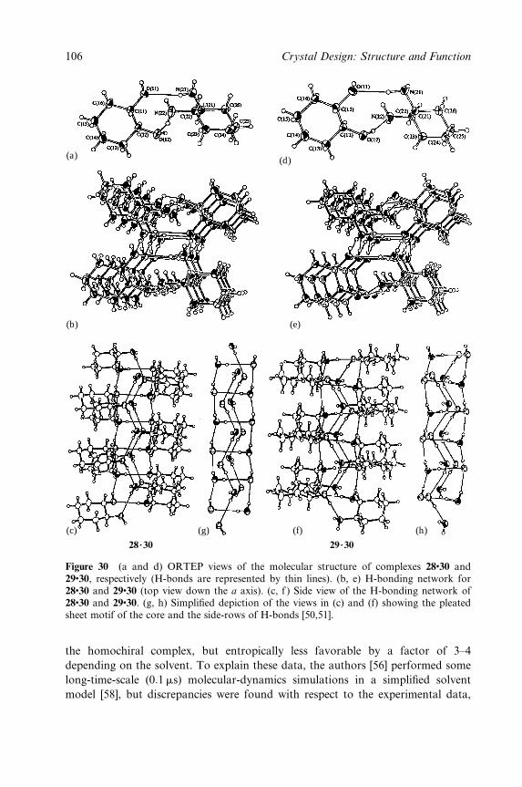
(a) (d)
(b)
(c) (g)
29.3028.30
(f) (h)
(e)
Figure 30 (a and d) ORTEP views of the molecular structure of complexes 28�30 and29�30, respectively (H-bonds are represented by thin lines). (b, e) H-bonding network for28�30 and 29�30 (top view down the a axis). (c, f ) Side view of the H-bonding network of28�30 and 29�30. (g, h) Simpli®ed depiction of the views in (c) and (f) showing the pleatedsheet motif of the core and the side-rows of H-bonds [50,51].
the homochiral complex, but entropically less favorable by a factor of 3±4
depending on the solvent. To explain these data, the authors [56] performed some
long-time-scale (0:1 ms) molecular-dynamics simulations in a simpli®ed solvent
model [58], but discrepancies were found with respect to the experimental data,
106 Crystal Design: Structure and Function
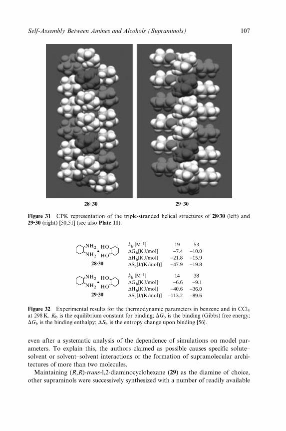
28.30 29.30
Figure 31 CPK representation of the triple-stranded helical structures of 28�30 (left) and29�30 (right) [50,51] (see also Plate 11).
NH2
NH2
HO
HO
28.30
NH2
NH2
HO
HO
29.30
53 −10.0−15.9−19.8
kb [M-1] 19 ∆Gb[KJ/mol] −7.4∆Hb[KJ/mol] −21.8∆Sb[J/(K/mol)] −47.9
38 −9.1
−36.0−89.6
kb [M-1] 14 ∆Gb[KJ/mol] −6.6∆Hb[KJ/mol] −40.6∆Sb[J/(K/mol)] −113.2
Figure 32 Experimental results for the thermodynamic parameters in benzene and in CCl4at 298 K. Kb is the equilibrium constant for binding; DGb is the binding (Gibbs) free energy;DGb is the binding enthalpy; DSb is the entropy change upon binding [56].
even after a systematic analysis of the dependence of simulations on model par-
ameters. To explain this, the authors claimed as possible causes speci®c solute±
solvent or solvent±solvent interactions or the formation of supramolecular archi-
tectures of more than two molecules.
Maintaining (R,R)-trans-l,2-diaminocyclohexane (29) as the diamine of choice,
other supraminols were successively synthesized with a number of readily available
Self-Assembly Between Amines and Alcohols (Supraminols) 107
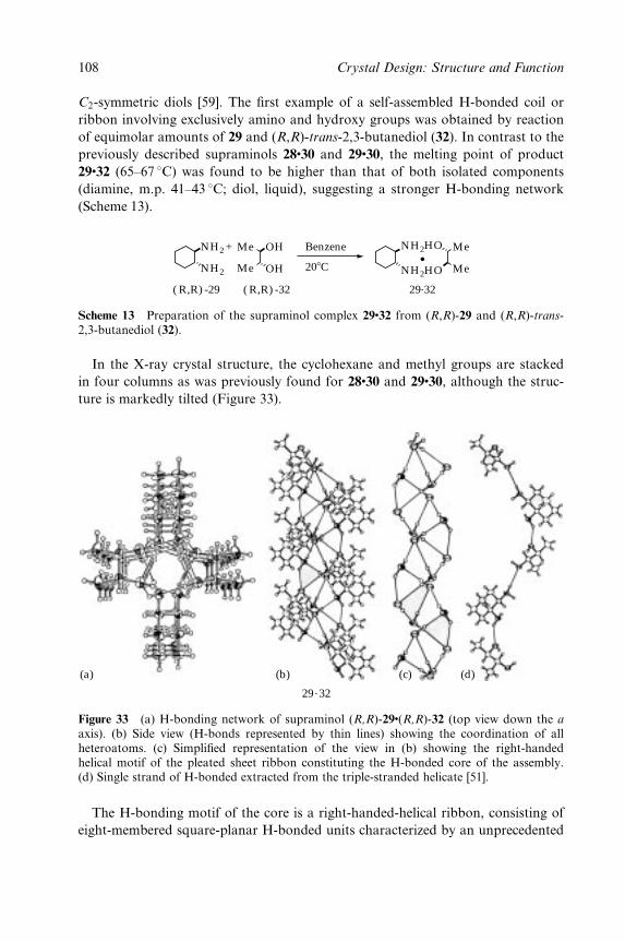
C2-symmetric diols [59]. The ®rst example of a self-assembled H-bonded coil or
ribbon involving exclusively amino and hydroxy groups was obtained by reaction
of equimolar amounts of 29 and (R,R)-trans-2,3-butanediol (32). In contrast to the
previously described supraminols 28�30 and 29�30, the melting point of product
29�32 (65±67 8C) was found to be higher than that of both isolated components
(diamine, m.p. 41±43 8C; diol, liquid), suggesting a stronger H-bonding network
(Scheme 13).
208C
Benzene+NH2
NH2 OH
OH
Me
Me NH2
NH2 MeHO
HO Me
( R,R) -29 ( R,R) -32 29.32
Scheme 13 Preparation of the supraminol complex 29�32 from (R,R)-29 and (R,R)-trans-2,3-butanediol (32).
In the X-ray crystal structure, the cyclohexane and methyl groups are stacked
in four columns as was previously found for 28�30 and 29�30, although the struc-
ture is markedly tilted (Figure 33).
(a) (b) (c) (d)
29.32
Figure 33 (a) H-bonding network of supraminol (R,R)-29�(R,R)-32 (top view down the a
axis). (b) Side view (H-bonds represented by thin lines) showing the coordination of allheteroatoms. (c) Simpli®ed representation of the view in (b) showing the right-handedhelical motif of the pleated sheet ribbon constituting the H-bonded core of the assembly.(d) Single strand of H-bonded extracted from the triple-stranded helicate [51].
The H-bonding motif of the core is a right-handed-helical ribbon, consisting of
eight-membered square-planar H-bonded units characterized by an unprecedented
108 Crystal Design: Structure and Function
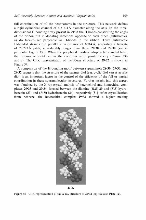
full coordination of all the heteroatoms in the structure. This network de®nes
a rigid cylindrical channel of 4.2±4.4AÊ diameter along the axis. In the three-
dimensional H-bonding array present in 29�32 the H-bonds constituting the edges
of the ribbon run in donating directions opposite to each other (antidromic),
as do face-to-face perpendicular H-bonds in the ribbon. Three antidromic
H-bonded strands run parallel at a distance of 6.764 AÊ , generating a helicate
of 20.293AÊ pitch, considerably longer than those 28�30 and 29�30 (see in
particular Figure 33d). While the peripheral residues adopt a left-handed helix,
the ribbon-like motif within the core has an opposite helicity (Figure 33b
and c). The CPK representation of the X-ray structure of 29�32 is shown in
Figure 34.
A comparison of the H-bonding motif between supraminols 28�30, 29�30, and
29�32 suggests that the structure of the partner diol (e.g. cyclic diol versus acyclic
diol) is an important factor in the control of the ef®ciency of the full or partial
coordination in these supramolecular structures. Further insight into this aspect
was obtained by the X-ray crystal analysis of heterochiral and homochiral com-
plexes 29�33 and 29�34, formed between the diamine (R,R)-29 and (S,S)-hydro-
benzoin (33) and (R,R)-hydrobenzoin (34), respectively [51]. After crystallization
from benzene, the heterochiral complex 29�33 showed a higher melting
29.32
Figure 34 CPK representation of the X-ray structure of 29�32 [51] (see also Plate 12).
Self-Assembly Between Amines and Alcohols (Supraminols) 109
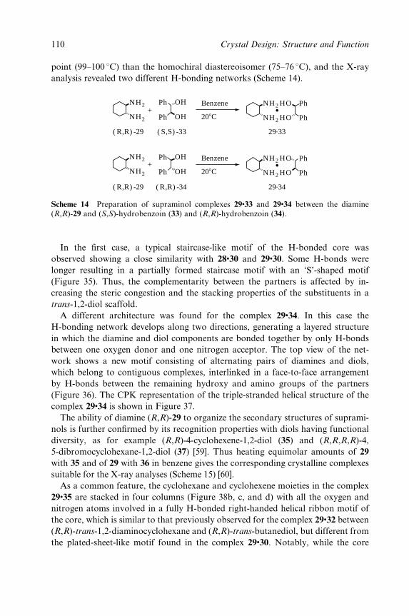
point (99±100 8C) than the homochiral diastereoisomer (75±76 8C), and the X-ray
analysis revealed two different H-bonding networks (Scheme 14).
208C
Benzene
208C
Benzene
+
+
NH2
NH2
NH2
NH2
OH
OHPh
Ph
OH
OHPh
Ph
Ph
PhNH2
NH2 HO
HO
( R,R) -29 ( S,S) -33
( R,R) -29 ( R,R) -34
29.33
Ph
PhNH2
NH2 HO
HO
29.34
Scheme 14 Preparation of supraminol complexes 29�33 and 29�34 between the diamine(R,R)-29 and (S,S)-hydrobenzoin (33) and (R,R)-hydrobenzoin (34).
In the ®rst case, a typical staircase-like motif of the H-bonded core was
observed showing a close similarity with 28�30 and 29�30. Some H-bonds were
longer resulting in a partially formed staircase motif with an `S'-shaped motif
(Figure 35). Thus, the complementarity between the partners is affected by in-
creasing the steric congestion and the stacking properties of the substituents in a
trans-1,2-diol scaffold.
A different architecture was found for the complex 29�34. In this case the
H-bonding network develops along two directions, generating a layered structure
in which the diamine and diol components are bonded together by only H-bonds
between one oxygen donor and one nitrogen acceptor. The top view of the net-
work shows a new motif consisting of alternating pairs of diamines and diols,
which belong to contiguous complexes, interlinked in a face-to-face arrangement
by H-bonds between the remaining hydroxy and amino groups of the partners
(Figure 36). The CPK representation of the triple-stranded helical structure of the
complex 29�34 is shown in Figure 37.
The ability of diamine (R,R)-29 to organize the secondary structures of suprami-
nols is further con®rmed by its recognition properties with diols having functional
diversity, as for example (R,R)-4-cyclohexene-1,2-diol (35) and (R,R,R,R)-4,
5-dibromocyclohexane-1,2-diol (37) [59]. Thus heating equimolar amounts of 29
with 35 and of 29 with 36 in benzene gives the corresponding crystalline complexes
suitable for the X-ray analyses (Scheme 15) [60].
As a common feature, the cyclohexane and cyclohexene moieties in the complex
29�35 are stacked in four columns (Figure 38b, c, and d) with all the oxygen and
nitrogen atoms involved in a fully H-bonded right-handed helical ribbon motif of
the core, which is similar to that previously observed for the complex 29�32 between
(R,R)-trans-1,2-diaminocyclohexane and (R,R)-trans-butanediol, but different from
the plated-sheet-like motif found in the complex 29�30. Notably, while the core
110 Crystal Design: Structure and Function
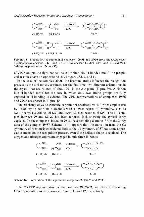
208C
Benzene
208C
Benzene
+
+
NH2
NH2
NH2
NH2
( R,R) -35( R,R) -29
( R,R) -29 ( R,R,R,R) -36
29.35
29.36
OH
OH
NH2
NH2
HO
HO
OHBr
Br OH
NH2
NH2 BrHO
HO Br
Scheme 15 Preparation of supraminol complexes 29�35 and 29�36 from the (R,R)-trans-1,2-diaminocyclohexane (29) and (R,R)-4-cyclohexene-1,2-diol (35) and (R,R,R,R)-4,5-dibromocyclohexane-1,2-diol (36).
of 29�35 adopts the right-handed helical ribbon-like H-bonded motif, the periph-
eral residues have an opposite helicity (Figure 38d, e, and f).
In the case of the complex 29�36, the bromine atoms in¯uence the recognition
process as the diol moiety assumes, for the ®rst time, two different orientations in
the crystal that are rotated of about 20 8 in the a±c plane (Figure 39). A ribbon
like H-bonded motif for the core in which only two amino groups are fully
engaged in H-bonding is evident. The CPK representations of complexes 29�35
and 29�36 are shown in Figure 40.
The ef®ciency of 29 to generate supraminol architectures is further emphasized
by its ability to coordinate alcohols with a lower degree of symmetry, such as
(S)-1-phenyl-1,2-ethanediol (37) and meso-1,2-cyclohexanediol (38). The 1:1 com-
plex between 29 and (S)-37 has been reported [61], showing the typical array
expected for the complexes based on 29 as the assembling diamine. From the X-ray
data of the complex 29�37 (Scheme 16) it appears that the transition from the C2
symmetry of previously considered diols to the C1 symmetry of 37 had some appre-
ciable effects on the recognition process, even if the helicate shape is retained. The
oxygen and nitrogen atoms are engaged in only three H-bonds.
208C
Benzene
208C
Benzene
+NH2
NH2
+NH2
NH2
( R,R) -37( R,R) -29 29.37
( R,R) -38( R,R) -29 29.38
OH
OH
NH2
NH2
HO
HO
OH
OHPh
NH2
NH2
PhHO
HO
Scheme 16 Preparation of the supraminol complexes 29�(S)-37 and 29�38.
The ORTEP representation of the complex 29�(S)-37, and the corresponding
CPK representations are shown in Figures 41 and 42, respectively.
Self-Assembly Between Amines and Alcohols (Supraminols) 111
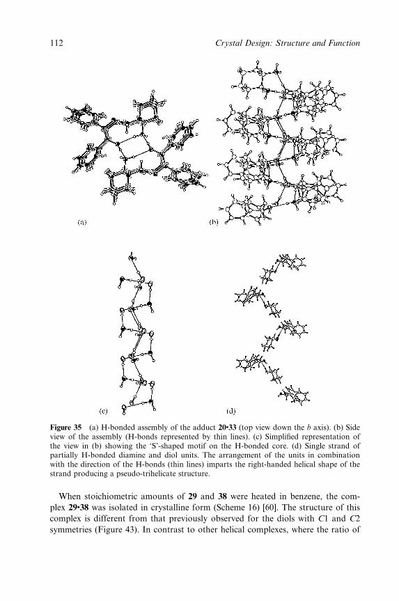
Figure 35 (a) H-bonded assembly of the adduct 20�33 (top view down the b axis). (b) Sideview of the assembly (H-bonds represented by thin lines). (c) Simpli®ed representation ofthe view in (b) showing the `S'-shaped motif on the H-bonded core. (d) Single strand ofpartially H-bonded diamine and diol units. The arrangement of the units in combinationwith the direction of the H-bonds (thin lines) imparts the right-handed helical shape of thestrand producing a pseudo-trihelicate structure.
When stoichiometric amounts of 29 and 38 were heated in benzene, the com-
plex 29�38 was isolated in crystalline form (Scheme 16) [60]. The structure of this
complex is different from that previously observed for the diols with C1 and C2
symmetries (Figure 43). In contrast to other helical complexes, where the ratio of
AQ2
112 Crystal Design: Structure and Function
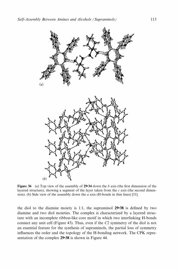
Figure 36 (a) Top view of the assembly of 29�34 down the b axis (the ®rst dimension of thelayered structure), showing a segment of the layer taken from the c axis (the second dimen-sion). (b) Side view of the assembly down the a axis (H-bonds in thin lines) [51].
the diol to the diamine moiety is 1:1, the supraminol 29�38 is de®ned by two
diamine and two diol moieties. The complex is characterized by a layered struc-
ture with an incomplete ribbon-like core motif in which two interlinking H-bonds
connect any unit cell (Figure 43). Thus, even if the C2 symmetry of the diol is not
an essential feature for the synthesis of supraminols, the partial loss of symmetry
in¯uences the order and the topology of the H-bonding network. The CPK repre-
sentation of the complex 29�38 is shown in Figure 44.
Self-Assembly Between Amines and Alcohols (Supraminols) 113
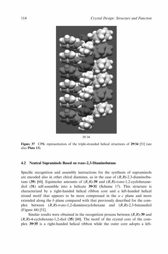
29.34
Figure 37 CPK representation of the triple-stranded helical structures of 29�34 [51] (seealso Plate 13).
4.2 Neutral Supraminols Based on trans-2,3-Diaminobutane
Speci®c recognition and assembly instructions for the synthesis of supraminols
are encoded also in other chiral diamines, as in the case of (R,R)-2,3-diaminobu-
tane (39) [60]. Equimolar amounts of (R,R)-39 and (R,R)-trans-1,2-cyclohexane-
diol (31) self-assemble into a helicate 39�31 (Scheme 17). This structure is
characterized by a right-handed helical ribbon core and a left-handed helical
strand motif that appears to be more compressed in the a±c plane and more
extended along the b plane compared with that previously described for the com-
plex between (R,R)-trans-1,2-diaminocyclohexane and (R,R)-2,3-butanediol
(Figure 44) [51].
Similar results were obtained in the recognition process between (R,R)-39 and
(R,R)-4-cyclohexene-1,2-diol (35) [60]. The motif of the crystal core of the com-
plex 39�35 is a right-handed helical ribbon while the outer core adopts a left-
114 Crystal Design: Structure and Function
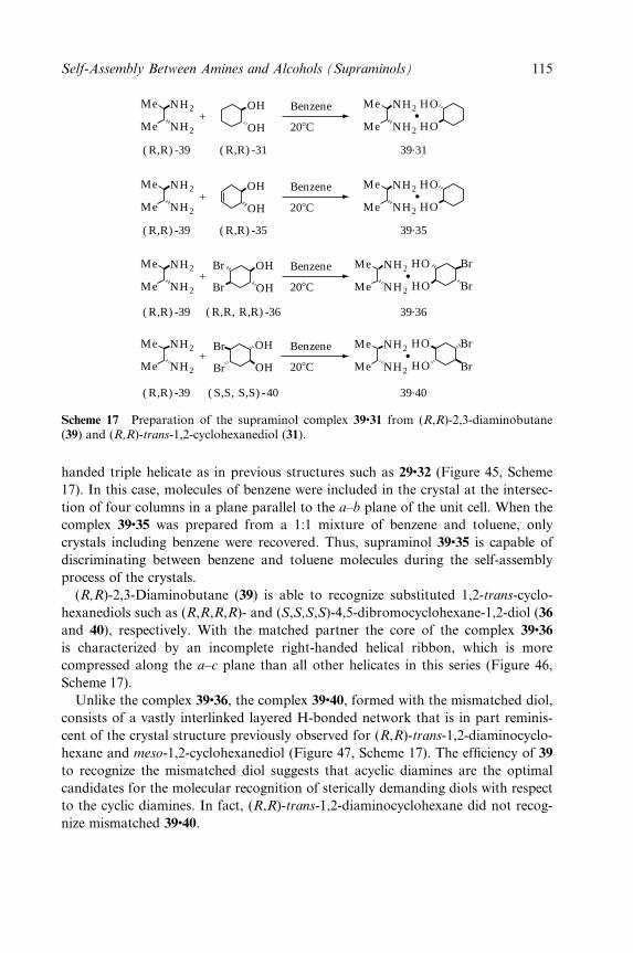
208C
Benzene+
( R,R) -31( R,R) -39 39.31
OH
OH
NH2
NH2
Me
Me HO
HONH2
NH2
Me
Me
208C
Benzene+
( R,R) -35( R,R) -39
NH2
NH2
Me
Me
39.35
HO
HONH2
NH2
Me
Me
OH
OH
208C
Benzene
( R,R, R,R) -36( R,R) -39
+NH2
NH2
Me
Me
39.36
OHBr
Br OH
NH2
NH2
Me
Me
HO Br
BrHO
208C
Benzene
( S,S, S,S) -40( R,R) -39
+NH2
NH2
Me
Me
39.40
Br
Br
OH
OH
NH2
NH2
Me
Me
HO Br
BrHO
Scheme 17 Preparation of the supraminol complex 39�31 from (R,R)-2,3-diaminobutane(39) and (R,R)-trans-1,2-cyclohexanediol (31).
handed triple helicate as in previous structures such as 29�32 (Figure 45, Scheme
17). In this case, molecules of benzene were included in the crystal at the intersec-
tion of four columns in a plane parallel to the a±b plane of the unit cell. When the
complex 39�35 was prepared from a 1:1 mixture of benzene and toluene, only
crystals including benzene were recovered. Thus, supraminol 39�35 is capable of
discriminating between benzene and toluene molecules during the self-assembly
process of the crystals.
(R,R)-2,3-Diaminobutane (39) is able to recognize substituted 1,2-trans-cyclo-
hexanediols such as (R,R,R,R)- and (S,S,S,S)-4,5-dibromocyclohexane-1,2-diol (36
and 40), respectively. With the matched partner the core of the complex 39�36
is characterized by an incomplete right-handed helical ribbon, which is more
compressed along the a±c plane than all other helicates in this series (Figure 46,
Scheme 17).
Unlike the complex 39�36, the complex 39�40, formed with the mismatched diol,
consists of a vastly interlinked layered H-bonded network that is in part reminis-
cent of the crystal structure previously observed for (R,R)-trans-1,2-diaminocyclo-
hexane and meso-1,2-cyclohexanediol (Figure 47, Scheme 17). The ef®ciency of 39
to recognize the mismatched diol suggests that acyclic diamines are the optimal
candidates for the molecular recognition of sterically demanding diols with respect
to the cyclic diamines. In fact, (R,R)-trans-1,2-diaminocyclohexane did not recog-
nize mismatched 39�40.
Self-Assembly Between Amines and Alcohols (Supraminols) 115

C(16)
C(14)
C(13)
C(11)
O(12)
O(11)N(21) C(26)
C(25)
C(24)
C(23)
C(21)
N(22)
C(15)
NH2
NH2
HO
HO
(a)
(b) (c)
(f)
(d) (e)
(R,R )- (R,R )-
29.35
Figure 38 ORTEP views of the adduct 29�35 [60].
116 Crystal Design: Structure and Function
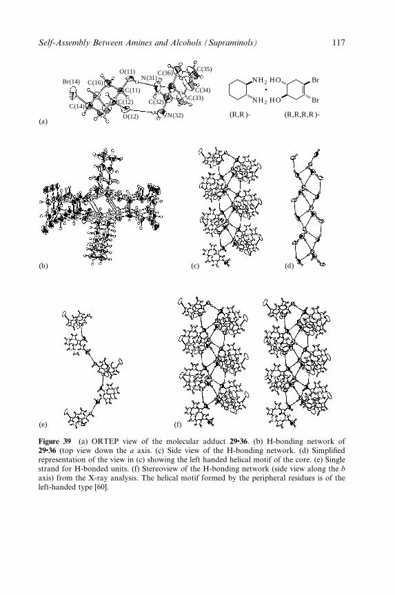
Br(14) C(16)
C(14)
O(11)
C(11)
C(12)
O(12)
N(31)C(36)
C(35)
C(34)C(33)
N(32)
C(32) NH2
NH2
HO
HO
Br
Br
(R,R )- (R,R,R,R )-(a)
(b) (c)
(f)
(d)
(e)
Figure 39 (a) ORTEP view of the molecular adduct 29�36. (b) H-bonding network of29�36 (top view down the a axis. (c) Side view of the H-bonding network. (d) Simpli®edrepresentation of the view in (c) showing the left handed helical motif of the core. (e) Singlestrand for H-bonded units. (f) Stereoview of the H-bonding network (side view along the b
axis) from the X-ray analysis. The helical motif formed by the peripheral residues is of theleft-handed type [60].
Self-Assembly Between Amines and Alcohols (Supraminols) 117
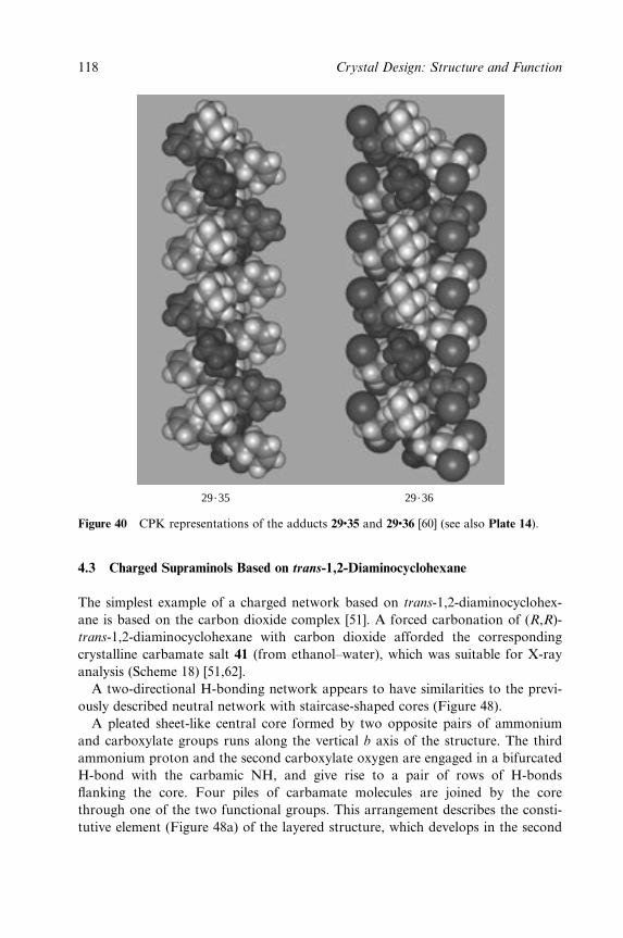
29.35 29.36
Figure 40 CPK representations of the adducts 29�35 and 29�36 [60] (see also Plate 14).
4.3 Charged Supraminols Based on trans-1,2-Diaminocyclohexane
The simplest example of a charged network based on trans-1,2-diaminocyclohex-
ane is based on the carbon dioxide complex [51]. A forced carbonation of (R,R)-
trans-1,2-diaminocyclohexane with carbon dioxide afforded the corresponding
crystalline carbamate salt 41 (from ethanol±water), which was suitable for X-ray
analysis (Scheme 18) [51,62].
A two-directional H-bonding network appears to have similarities to the previ-
ously described neutral network with staircase-shaped cores (Figure 48).
A pleated sheet-like central core formed by two opposite pairs of ammonium
and carboxylate groups runs along the vertical b axis of the structure. The third
ammonium proton and the second carboxylate oxygen are engaged in a bifurcated
H-bond with the carbamic NH, and give rise to a pair of rows of H-bonds
¯anking the core. Four piles of carbamate molecules are joined by the core
through one of the two functional groups. This arrangement describes the consti-
tutive element (Figure 48a) of the layered structure, which develops in the second
118 Crystal Design: Structure and Function
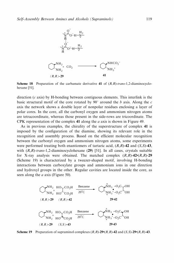
NH2
H
HH
H2HO
−O
−
O−
O−
N
N
N+
+
+
H2N+
NH2
CO2
NHCO2−
NH3++
(R,R)-29 41
Scheme 18 Preparation of the carbamate derivative 41 of (R,R)-trans-1,2-diaminocyclo-hexane [51].
direction (c axis) by H-bonding between contiguous elements. This interlink is the
basic structural motif of the core rotated by 908 around the b axis. Along the c
axis the network shows a double layer of nonpolar residues enclosing a layer of
polar cores. In the core, all the carbonyl oxygen and ammonium nitrogen atoms
are tetracoordinate, whereas those present in the side-rows are tricoordinate. The
CPK representation of the complex 41 along the a axis is shown in Figure 49.
As in previous examples, the chirality of the superstructure of complex 41 is
imposed by the con®guration of the diamine, showing its relevant role in the
recognition and assembly process. Based on the ef®cient molecular recognition
between the carbonyl oxygen and ammonium nitrogen atoms, some experiments
were performed treating both enantiomers of tartaric acid, (R,R)-42 and (S,S)-43,
with (R,R)-trans-1,2-diaminocyclohexane (29) [51]. In all cases, crystals suitable
for X-ray analysis were obtained. The matched complex (R,R)-42�(R,R)-29
(Scheme 19) is characterized by a tweezer-shaped motif, involving H-bonding
interactions between carboxylate groups and ammonium ions in one direction
and hydroxyl groups in the other. Regular cavities are located inside the core, as
seen along the a axis (Figure 50).
NH2
NH2
CO2HHO
HO CO2H
NH3
NH3++
+
+
(R,R)-29 (R,R)-42 29.42
OH−O2C
−O2C OH
Benzene
208C
NH2
NH2
CO2HHO
HO CO2H
NH3
NH3++
+
+
(R,R)-29 (S,S)-43 29.43
OH−O2C
−O2C OH
Benzene
208C
Scheme 19 Preparation of supraminol complexes (R,R)-29�(R,R)-42 and (S,S)-29�(R,R)-43.
Self-Assembly Between Amines and Alcohols (Supraminols) 119
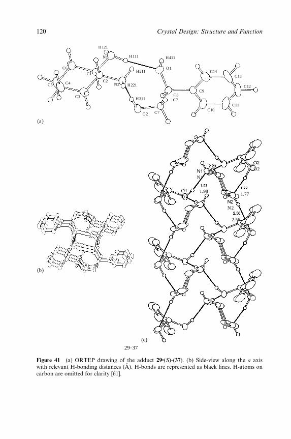
C5 C4
C3
C1
C2
N1
N2
H121
H111
H211
H221
H311
C7
C7
O2
O1
C8C9
C10
C14
C11
C12
C13
H411
C6
O11.98
N12.20
1.77
O2
N2
2.56
(a)
(b)
29.37
(c)
Figure 41 (a) ORTEP drawing of the adduct 29�(S)-(37). (b) Side-view along the a axiswith relevant H-bonding distances (AÊ ). H-bonds are represented as black lines. H-atoms oncarbon are omitted for clarity [61].
120 Crystal Design: Structure and Function
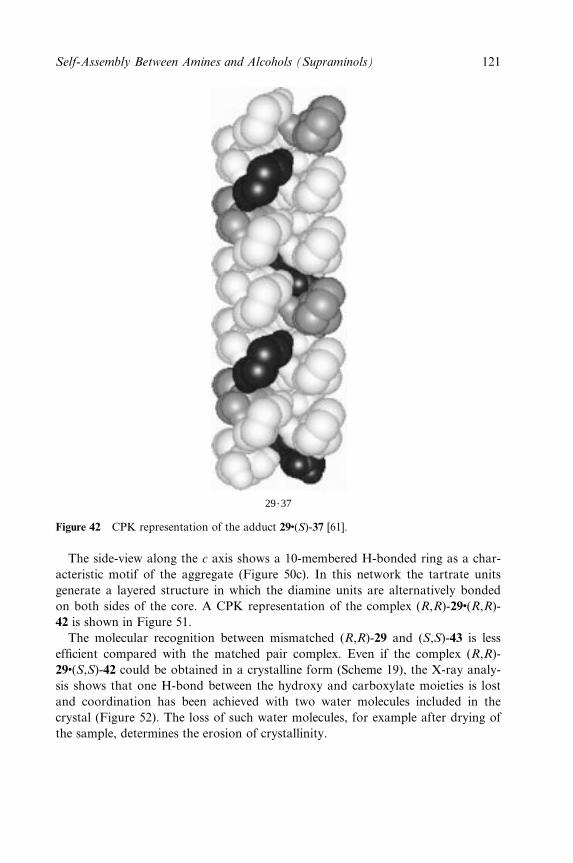
29.37
Figure 42 CPK representation of the adduct 29�(S)-37 [61].
The side-view along the c axis shows a 10-membered H-bonded ring as a char-
acteristic motif of the aggregate (Figure 50c). In this network the tartrate units
generate a layered structure in which the diamine units are alternatively bonded
on both sides of the core. A CPK representation of the complex (R,R)-29�(R,R)-
42 is shown in Figure 51.
The molecular recognition between mismatched (R,R)-29 and (S,S)-43 is less
ef®cient compared with the matched pair complex. Even if the complex (R,R)-
29�(S,S)-42 could be obtained in a crystalline form (Scheme 19), the X-ray analy-
sis shows that one H-bond between the hydroxy and carboxylate moieties is lost
and coordination has been achieved with two water molecules included in the
crystal (Figure 52). The loss of such water molecules, for example after drying of
the sample, determines the erosion of crystallinity.
Self-Assembly Between Amines and Alcohols (Supraminols) 121
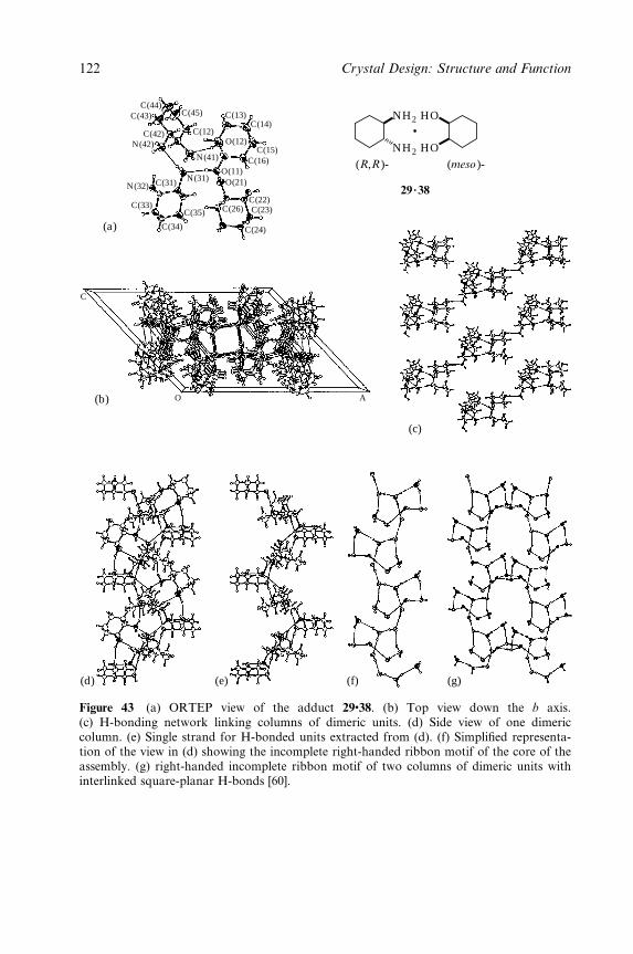
C(44)C(43)
C(42)N(42)
N(32) C(31)
C(33)
C(34)
C(35)
N(31)
N(41)
C(12)
C(45) C(13)C(14)
O(12)C(15)
C(16)O(11)O(21)
C(26)C(22)C(23)
C(24)
C
O A
NH2
NH2
HO
HO
(R,R )- (meso )-
(a)
(b)
(c)
(d) (e) (f) (g)
29.38
Figure 43 (a) ORTEP view of the adduct 29�38. (b) Top view down the b axis.(c) H-bonding network linking columns of dimeric units. (d) Side view of one dimericcolumn. (e) Single strand for H-bonded units extracted from (d). (f) Simpli®ed representa-tion of the view in (d) showing the incomplete right-handed ribbon motif of the core of theassembly. (g) right-handed incomplete ribbon motif of two columns of dimeric units withinterlinked square-planar H-bonds [60].
122 Crystal Design: Structure and Function
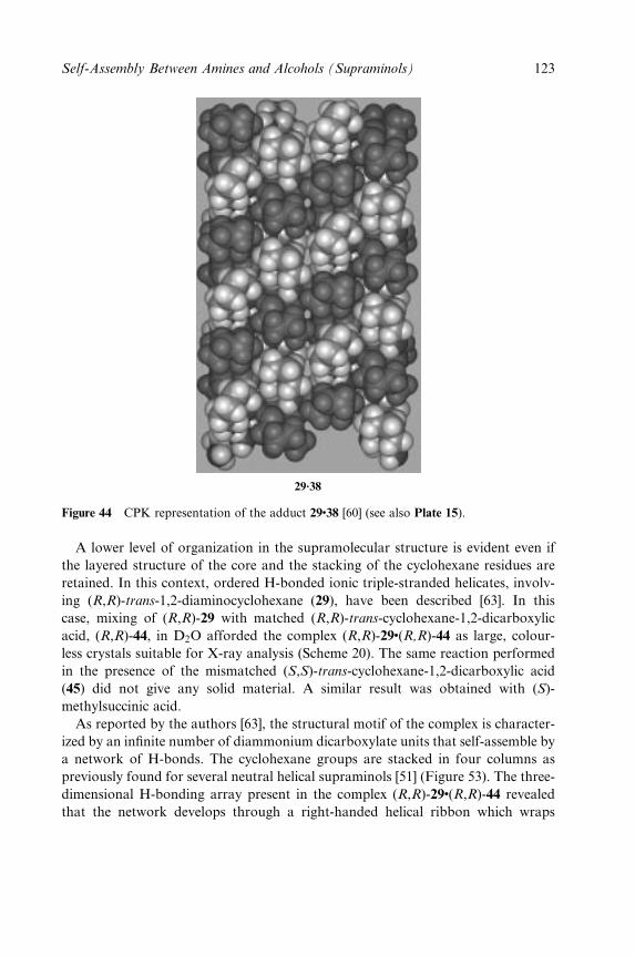
29.38
Figure 44 CPK representation of the adduct 29�38 [60] (see also Plate 15).
A lower level of organization in the supramolecular structure is evident even if
the layered structure of the core and the stacking of the cyclohexane residues are
retained. In this context, ordered H-bonded ionic triple-stranded helicates, involv-
ing (R,R)-trans-1,2-diaminocyclohexane (29), have been described [63]. In this
case, mixing of (R,R)-29 with matched (R,R)-trans-cyclohexane-1,2-dicarboxylic
acid, (R,R)-44, in D2O afforded the complex (R,R)-29�(R,R)-44 as large, colour-
less crystals suitable for X-ray analysis (Scheme 20). The same reaction performed
in the presence of the mismatched (S,S)-trans-cyclohexane-1,2-dicarboxylic acid
(45) did not give any solid material. A similar result was obtained with (S)-
methylsuccinic acid.
As reported by the authors [63], the structural motif of the complex is character-
ized by an in®nite number of diammonium dicarboxylate units that self-assemble by
a network of H-bonds. The cyclohexane groups are stacked in four columns as
previously found for several neutral helical supraminols [51] (Figure 53). The three-
dimensional H-bonding array present in the complex (R,R)-29�(R,R)-44 revealed
that the network develops through a right-handed helical ribbon which wraps
Self-Assembly Between Amines and Alcohols (Supraminols) 123
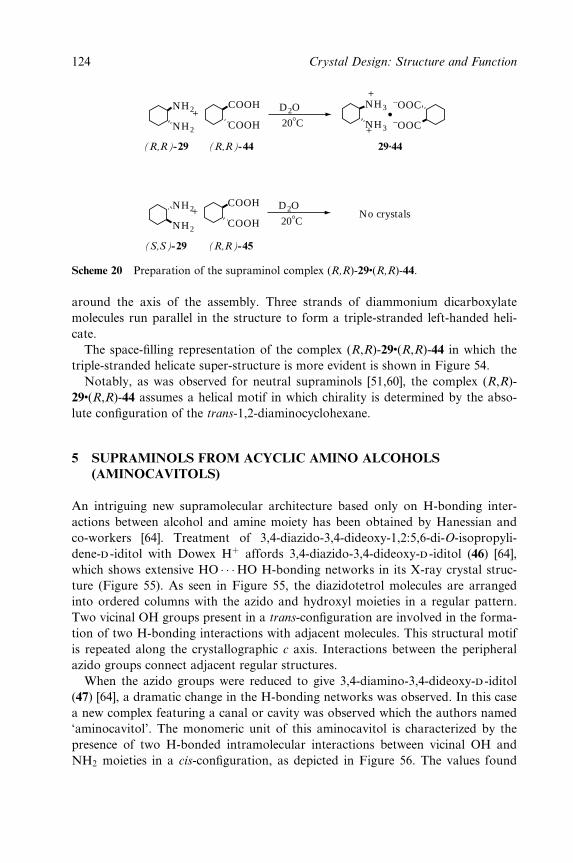
NH2
NH2
COOH
COOH
NH3
NH3
+
+
+
(R,R)-29 (R,R)-44 29.44
−OOC
−OOC
D2O
208C
NH2
NH2
COOH
COOH+
(S,S)-29 (R,R)-45
No crystalsD2O
208C
Scheme 20 Preparation of the supraminol complex (R,R)-29�(R,R)-44.
around the axis of the assembly. Three strands of diammonium dicarboxylate
molecules run parallel in the structure to form a triple-stranded left-handed heli-
cate.
The space-®lling representation of the complex (R,R)-29�(R,R)-44 in which the
triple-stranded helicate super-structure is more evident is shown in Figure 54.
Notably, as was observed for neutral supraminols [51,60], the complex (R,R)-
29�(R,R)-44 assumes a helical motif in which chirality is determined by the abso-
lute con®guration of the trans-1,2-diaminocyclohexane.
5 SUPRAMINOLS FROM ACYCLIC AMINO ALCOHOLS
(AMINOCAVITOLS)
An intriguing new supramolecular architecture based only on H-bonding inter-
actions between alcohol and amine moiety has been obtained by Hanessian and
co-workers [64]. Treatment of 3,4-diazido-3,4-dideoxy-1,2:5,6-di-O-isopropyli-
dene-d -iditol with Dowex H� affords 3,4-diazido-3,4-dideoxy-d -iditol (46) [64],
which shows extensive HO � � �HO H-bonding networks in its X-ray crystal struc-
ture (Figure 55). As seen in Figure 55, the diazidotetrol molecules are arranged
into ordered columns with the azido and hydroxyl moieties in a regular pattern.
Two vicinal OH groups present in a trans-con®guration are involved in the forma-
tion of two H-bonding interactions with adjacent molecules. This structural motif
is repeated along the crystallographic c axis. Interactions between the peripheral
azido groups connect adjacent regular structures.
When the azido groups were reduced to give 3,4-diamino-3,4-dideoxy-d -iditol
(47) [64], a dramatic change in the H-bonding networks was observed. In this case
a new complex featuring a canal or cavity was observed which the authors named
`aminocavitol'. The monomeric unit of this aminocavitol is characterized by the
presence of two H-bonded intramolecular interactions between vicinal OH and
NH2 moieties in a cis-con®guration, as depicted in Figure 56. The values found
124 Crystal Design: Structure and Function
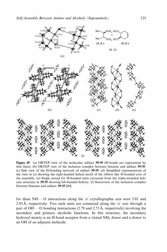
C(16)
C(15)
C(14)
C(13) O(12)
C(12)
C(11)
O(11)
N(22)
C(21)
C(22)
C(23)C(24)
N(23)
O C
B
A
(a)
(b) (c) (d) (e)
(f)
NH2
NH2
HO
HO
(R,R )- (R,R )-
Me
Me
39.35
Figure 45 (a) ORTEP view of the molecular adduct 39�35 (H-bonds are represented bythin lines). (b) ORTEP view of the inclusion complex between benzene and adduct 39�35.(c) Side view of the H-bonding network of adduct 39�35. (d) Simpli®ed representation ofthe view in (c) showing the right-handed helical motif of the ribbon like H-bonded core ofthe assembly. (e) Single strand for H-bonded units extracted from the triple-stranded heli-cate structure in 39�35 showing left-handed helicity. (f) Stereoview of the inclusion complexbetween benzene and adduct 39�35 [60].
for these NH � � �O interactions along the `a' crytallographic axis were 3.01 and
2.95AÊ , respectively. Two such units are connected along the `a' axis through a
pair of OH � � �O bonding interactions (2.79 and 2.73AÊ , respectively) involving the
secondary and primary alcoholic functions. In this structure, the secondary
hydroxyl moiety is an H-bond acceptor from a vicinal NH2 donor and a donor to
an OH of an adjacent molecule.
Self-Assembly Between Amines and Alcohols (Supraminols) 125

Br(14)
C(14)
C(13)
C(15)C(11)
O(11)N(22)
O(12)
C(23)
N(23)
C(22)
C(21)
C(24)
(b)
(a)
(c)
(f)
(d) (e)
39.36
Figure 46 (a) ORTEP view of the molecular adduct 39�36 (H-bonds are represented bythin lines). (b) H-bonding network of adduct 39�36. (c) Side view of the H-bonding net-work. (d) Simpli®ed representation of the view in (c) showing the right-handed helical motifof the ribbon like H-bonded core of the assembly. (e) Single strand for H-bonded unitsextracted from the triple-stranded helicate structure in 39�36 showing left-handed helicity.(f) Stereoview of the H-bonding network [60].
126 Crystal Design: Structure and Function
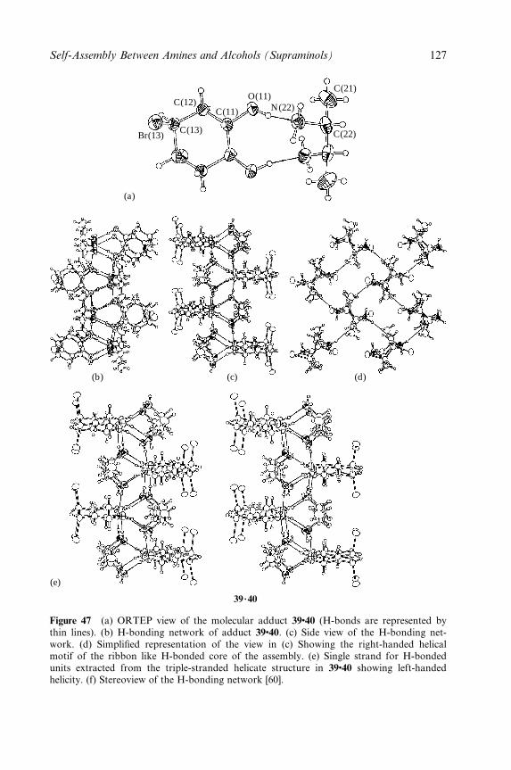
Br(13)C(13)
C(12)C(11)
O(11)N(22)
C(21)
C(22)
(a)
(b) (c)
(e)
(d)
39.40
Figure 47 (a) ORTEP view of the molecular adduct 39�40 (H-bonds are represented bythin lines). (b) H-bonding network of adduct 39�40. (c) Side view of the H-bonding net-work. (d) Simpli®ed representation of the view in (c) Showing the right-handed helicalmotif of the ribbon like H-bonded core of the assembly. (e) Single strand for H-bondedunits extracted from the triple-stranded helicate structure in 39�40 showing left-handedhelicity. (f) Stereoview of the H-bonding network [60].
Self-Assembly Between Amines and Alcohols (Supraminols) 127
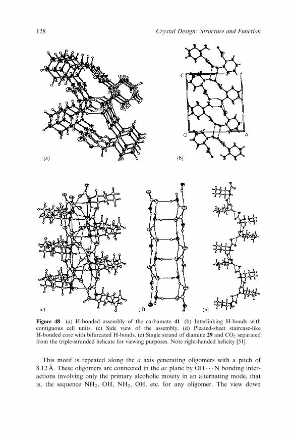
Figure 48 (a) H-bonded assembly of the carbamate 41. (b) Interlinking H-bonds withcontiguous cell units. (c) Side view of the assembly. (d) Pleated-sheet staircase-likeH-bonded core with bifurcated H-bonds. (e) Single strand of diamine 29 and CO2 separatedfrom the triple-stranded helicate for viewing purposes. Note right-handed helicity [51].
This motif is repeated along the a axis generating oligomers with a pitch of
8.12 AÊ . These oligomers are connected in the ac plane by OH � � �N bonding inter-
actions involving only the primary alcoholic moiety in an alternating mode, that
is, the sequence NH2, OH, NH2, OH, etc. for any oligomer. The view down
128 Crystal Design: Structure and Function
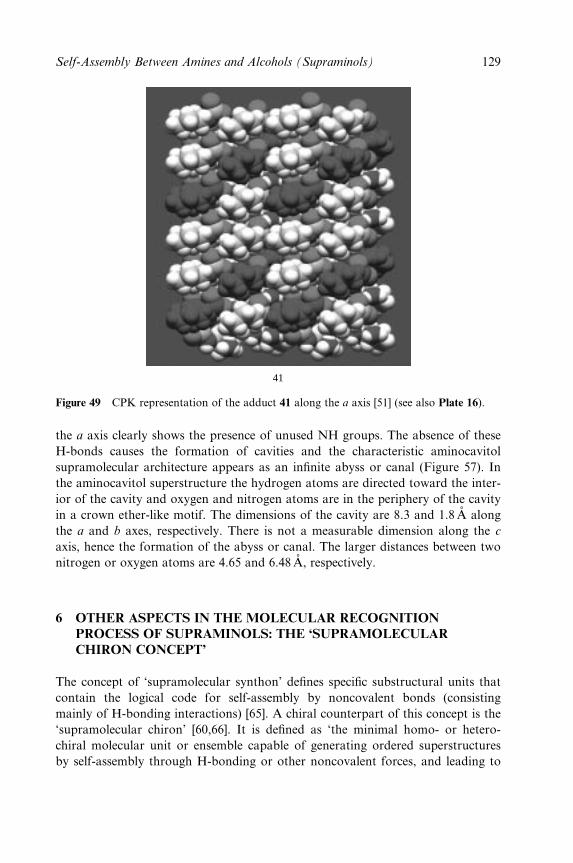
41
Figure 49 CPK representation of the adduct 41 along the a axis [51] (see also Plate 16).
the a axis clearly shows the presence of unused NH groups. The absence of these
H-bonds causes the formation of cavities and the characteristic aminocavitol
supramolecular architecture appears as an in®nite abyss or canal (Figure 57). In
the aminocavitol superstructure the hydrogen atoms are directed toward the inter-
ior of the cavity and oxygen and nitrogen atoms are in the periphery of the cavity
in a crown ether-like motif. The dimensions of the cavity are 8.3 and 1.8 AÊ along
the a and b axes, respectively. There is not a measurable dimension along the c
axis, hence the formation of the abyss or canal. The larger distances between two
nitrogen or oxygen atoms are 4.65 and 6.48AÊ , respectively.
6 OTHER ASPECTS IN THE MOLECULAR RECOGNITION
PROCESS OF SUPRAMINOLS: THE `SUPRAMOLECULAR
CHIRON CONCEPT'
The concept of `supramolecular synthon' de®nes speci®c substructural units that
contain the logical code for self-assembly by noncovalent bonds (consisting
mainly of H-bonding interactions) [65]. A chiral counterpart of this concept is the
`supramolecular chiron' [60,66]. It is de®ned as `the minimal homo- or hetero-
chiral molecular unit or ensemble capable of generating ordered superstructures
by self-assembly through H-bonding or other noncovalent forces, and leading to
Self-Assembly Between Amines and Alcohols (Supraminols) 129
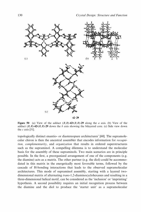
Figure 50 (a) View of the adduct (R,R)-42�(R,R)-29 along the a axis. (b) View of theadduct (R,R)-42�(R,R)-29 down the b axis showing the bilayered core. (c) Side view downthe c axis [51].
topologically distinct enantio- or diastereopure architectures' [60]. The supramole-
cular chiron is then the ancestral assembler that encodes information for recogni-
tion, complementarity, and organization that results in ordered superstructures
such as the supraminol. A compelling dilemma is to understand the molecular
basis for the assembly of these supraminols. Two main scenarios are in principle
possible. In the ®rst, a preorganized arrangement of one of the components (e.g.
the diamine) acts as a matrix. The other partner (e.g. the diol) could be accommo-
dated in this matrix in the energetically most favorable terms, followed by the
cascade of H-bonding interactions that leads to the observed supramolecular
architectures. This mode of supraminol assembly, starting with a layered two-
dimensional matrix of alternating trans-1,2-diaminocyclohexanes and resulting in a
three-dimensional helical motif, can be considered as the `inclusion' or `imprinting'
hypothesis. A second possibility requires an initial recognition process between
the diamine and the diol to produce the `starter unit' as a supramolecular
130 Crystal Design: Structure and Function
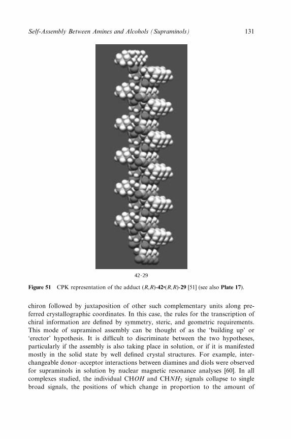
42.29
Figure 51 CPK representation of the adduct (R,R)-42�(R,R)-29 [51] (see also Plate 17).
chiron followed by juxtaposition of other such complementary units along pre-
ferred crystallographic coordinates. In this case, the rules for the transcription of
chiral information are de®ned by symmetry, steric, and geometric requirements.
This mode of supraminol assembly can be thought of as the `building up' or
`erector' hypothesis. It is dif®cult to discriminate between the two hypotheses,
particularly if the assembly is also taking place in solution, or if it is manifested
mostly in the solid state by well de®ned crystal structures. For example, inter-
changeable donor±acceptor interactions between diamines and diols were observed
for supraminols in solution by nuclear magnetic resonance analyses [60]. In all
complexes studied, the individual CHOH and CHNH2 signals collapse to single
broad signals, the positions of which change in proportion to the amount of
Self-Assembly Between Amines and Alcohols (Supraminols) 131
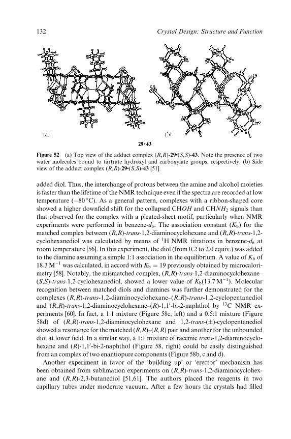
Figure 52 (a) Top view of the adduct complex (R,R)-29�(S,S)-43. Note the presence of twowater molecules bound to tartrate hydroxyl and carboxylate groups, respectively. (b) Sideview of the adduct complex (R,R)-29�(S,S)-43 [51].
added diol. Thus, the interchange of protons between the amine and alcohol moieties
is faster than the lifetime of the NMR technique even if the spectra are recorded at low
temperature (ÿ80 �C). As a general pattern, complexes with a ribbon-shaped core
showed a higher down®eld shift for the collapsed CHOH and CHNH2 signals than
that observed for the complex with a pleated-sheet motif, particularly when NMR
experiments were performed in benzene-d6. The association constant (Kb) for the
matched complex between (R,R)-trans-1,2-diaminocyclohexane and (R,R)-trans-1,2-
cyclohexanediol was calculated by means of 1H NMR titrations in benzene-d6 at
room temperature [56]. In this experiment, the diol (from 0.2 to 2.0 equiv.) was added
to the diamine assuming a simple 1:1 association in the equilibrium. A value of Kb of
18:3 Mÿ1 was calculated, in accord with Kb � 19 previously obtained by microcalori-
metry [58]. Notably, the mismatched complex, (R,R)-trans-1,2-diaminocyclohexane±
(S,S)-trans-1,2-cyclohexanediol, showed a lower value of Kb(13:7Mÿ1). Molecular
recognition between matched diols and diamines was further demonstrated for the
complexes (R,R)-trans-1,2-diaminocyclohexane±(R,R)-trans-1,2-cyclopentanediol
and (R,R)-trans-1,2-diaminocyclohexane±(R)-1,10-bi-2-naphthol by 13C NMR ex-
periments [60]. In fact, a 1:1 mixture (Figure 58c, left) and a 0.5:1 mixture (Figure
58d) of (R,R)-trans-1,2-diaminocyclohexane and 1,2-trans-(�)-cyclopentanediol
showed a resonance for the matched (R,R)±(R,R) pair and another for the unbounded
diol at lower ®eld. In a similar way, a 1:1 mixture of racemic trans-1,2-diaminocyclo-
hexane and (R)-1,10-bi-2-naphthol (Figure 58, right) could be easily distinguished
from an complex of two enantiopure components (Figure 58b, c and d).
Another experiment in favor of the `building up' or `erector' mechanism has
been obtained from sublimation experiments on (R,R)-trans-1,2-diaminocyclohex-
ane and (R,R)-2,3-butanediol [51,61]. The authors placed the reagents in two
capillary tubes under moderate vacuum. After a few hours the crystals had ®lled
132 Crystal Design: Structure and Function
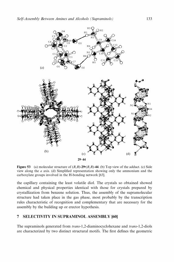
O4
C3
C4
C5
C6
O1
C7
C1
C2C8 O3
O2
H5
H6
N2
H4
C10
C11 C12
C13
C14C9
H2H3
H1
N1
(a)
N2
N1
N1
N2
O3
O2
O4
(b)(c) (d)
29.44
Figure 53 (a) molecular structure of (R,R)-29�(R,R)-44. (b) Top view of the adduct. (c) Sideview along the a axis. (d) Simpli®ed representation showing only the ammonium and thecarboxylate groups involved in the H-bonding network [63].
the capillary containing the least volatile diol. The crystals so obtained showed
chemical and physical properties identical with those for crystals prepared by
crystallization from benzene solution. Thus, the assembly of the supramolecular
structure had taken place in the gas phase, most probably by the transcription
rules characteristic of recognition and complementary that are necessary for the
assembly by the building up or erector hypothesis.
7 SELECTIVITY IN SUPRAMINOL ASSEMBLY [60]
The supraminols generated from trans-1,2-diaminocyclohexane and trans-1,2-diols
are characterized by two distinct structural motifs. The ®rst de®nes the geometric
Self-Assembly Between Amines and Alcohols (Supraminols) 133
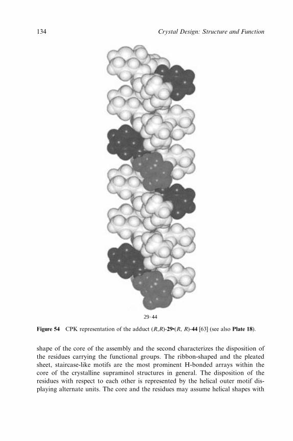
29.44
Figure 54 CPK representation of the adduct (R,R)-29�(R, R)-44 [63] (see also Plate 18).
shape of the core of the assembly and the second characterizes the disposition of
the residues carrying the functional groups. The ribbon-shaped and the pleated
sheet, staircase-like motifs are the most prominent H-bonded arrays within the
core of the crystalline supraminol structures in general. The disposition of the
residues with respect to each other is represented by the helical outer motif dis-
playing alternate units. The core and the residues may assume helical shapes with
134 Crystal Design: Structure and Function

N3
OH OH
HO
OH
N3
N(33)
N(43)N(42)N(41)
N(32)
N(31)O(1)
C(1)
C(2)
C(3)
C(5)C(6)
O(6)
C(4) O(5)
O(2)
46
Figure 55 Supramolecular structure of 3,4-diazido-3,4-dideoxy-d -iditol (46) [64].
Self-Assembly Between Amines and Alcohols (Supraminols) 135
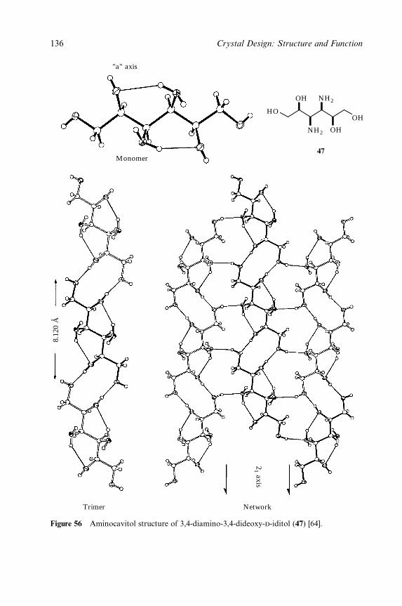
8.12
0 A
21 axis
Monomer
"a" axis
OHHO
OH
NH2
NH2
OH
NetworkTrimer
47
Figure 56 Aminocavitol structure of 3,4-diamino-3,4-dideoxy-d-iditol (47) [64].
136 Crystal Design: Structure and Function
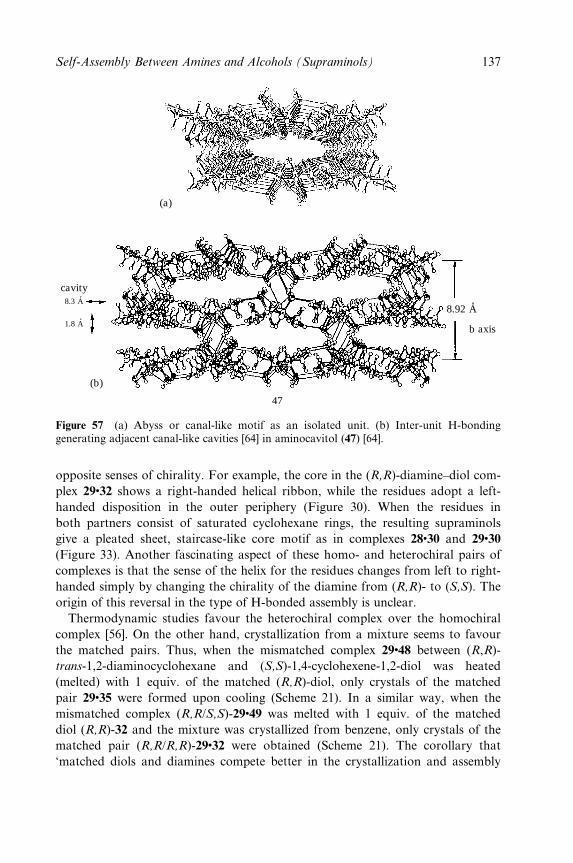
cavity8.3 A
1.8 A
8.92 A
b axis
(b)
(a)
47
Figure 57 (a) Abyss or canal-like motif as an isolated unit. (b) Inter-unit H-bondinggenerating adjacent canal-like cavities [64] in aminocavitol (47) [64].
opposite senses of chirality. For example, the core in the (R,R)-diamine±diol com-
plex 29�32 shows a right-handed helical ribbon, while the residues adopt a left-
handed disposition in the outer periphery (Figure 30). When the residues in
both partners consist of saturated cyclohexane rings, the resulting supraminols
give a pleated sheet, staircase-like core motif as in complexes 28�30 and 29�30
(Figure 33). Another fascinating aspect of these homo- and heterochiral pairs of
complexes is that the sense of the helix for the residues changes from left to right-
handed simply by changing the chirality of the diamine from (R,R)- to (S,S). The
origin of this reversal in the type of H-bonded assembly is unclear.
Thermodynamic studies favour the heterochiral complex over the homochiral
complex [56]. On the other hand, crystallization from a mixture seems to favour
the matched pairs. Thus, when the mismatched complex 29�48 between (R,R)-
trans-1,2-diaminocyclohexane and (S,S)-1,4-cyclohexene-1,2-diol was heated
(melted) with 1 equiv. of the matched (R,R)-diol, only crystals of the matched
pair 29�35 were formed upon cooling (Scheme 21). In a similar way, when the
mismatched complex (R,R/S,S)-29�49 was melted with 1 equiv. of the matched
diol (R,R)-32 and the mixture was crystallized from benzene, only crystals of the
matched pair (R,R/R,R)-29�32 were obtained (Scheme 21). The corollary that
`matched diols and diamines compete better in the crystallization and assembly
Self-Assembly Between Amines and Alcohols (Supraminols) 137
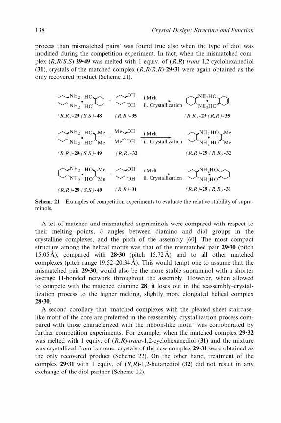
process than mismatched pairs' was found true also when the type of diol was
modi®ed during the competition experiment. In fact, when the mismatched com-
plex (R,R/S,S)-29�49 was melted with 1 equiv. of (R,R)-trans-1,2-cyclohexanediol
(31), crystals of the matched complex (R,R/R,R)-29�31 were again obtained as the
only recovered product (Scheme 21).
NH2
NH2
OHHO
HO OH
NH2
NH2
(R,R)-29.(S,S)-48 (R,R)-35 (R,R)-29.(R,R)-35
HO
HO
i.Melt
ii. Crystallization
i.Melt
ii. Crystallization
+
NH2
NH2
OHHO
HO
Me
Me
Me
Me OH
(R,R)-29.(S,S)-49 (R,R)-32
+
OH
OH
NH2
NH2
(R,R)-31 (R,R)-29.(R,R)-31
HO
HO
i.Melt
ii. Crystallization
NH2
NH2
(R,R)-29.(R,R)-32
HO
HO
Me
Me
NH2
NH2
HO
HO
Me
Me
(R,R)-29.(S,S)-49
+
Scheme 21 Examples of competition experiments to evaluate the relative stability of supra-minols.
A set of matched and mismatched supraminols were compared with respect to
their melting points, d angles between diamino and diol groups in the
crystalline complexes, and the pitch of the assembly [60]. The most compact
structure among the helical motifs was that of the mismatched pair 29�30 (pitch
15.05 AÊ ), compared with 28�30 (pitch 15.72AÊ ) and to all other matched
complexes (pitch range 19.52±20.34AÊ ). This would tempt one to assume that the
mismatched pair 29�30, would also be the more stable supraminol with a shorter
average H-bonded network throughout the assembly. However, when allowed
to compete with the matched diamine 28, it loses out in the reassembly±crystal-
lization process to the higher melting, slightly more elongated helical complex
28�30.
A second corollary that `matched complexes with the pleated sheet staircase-
like motif of the core are preferred in the reassembly±crystallization process com-
pared with those characterized with the ribbon-like motif ' was corroborated by
further competition experiments. For example, when the matched complex 29�32
was melted with 1 equiv. of (R,R)-trans-1,2-cyclohexanediol (31) and the mixture
was crystallized from benzene, crystals of the new complex 29�31 were obtained as
the only recovered product (Scheme 22). On the other hand, treatment of the
complex 29�31 with 1 equiv. of (R,R)-1,2-butanediol (32) did not result in any
exchange of the diol partner (Scheme 22).
138 Crystal Design: Structure and Function
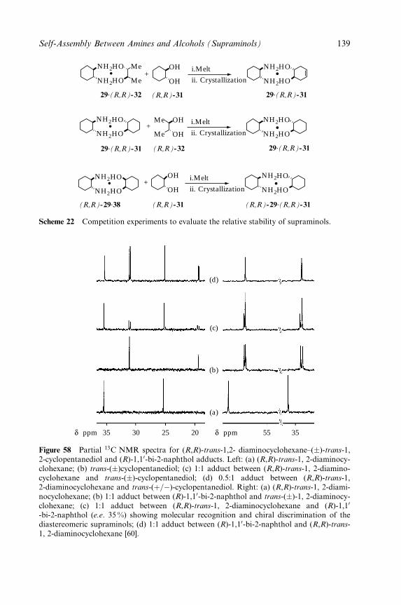
NH2
NH2
OHHO
HO
Me
Me OH
NH2
NH2
29.(R,R)-32 (R,R)-31 29.(R,R)-31
HO
HO
i.Melt
ii. Crystallization
i.Melt
ii. Crystallization
+
NH2
NH2
OHHO
HO
Me
Me OH
29.(R,R)-31 (R,R)-32
NH2
NH2
HO
HO
+NH2
NH2
HO
HO
OH
OH
NH2
NH2
(R,R)-31 (R,R)-29.(R,R)-31
HO
HO
i.Melt
ii. Crystallization
29.(R,R)-31
(R,R)-29.38
+
Scheme 22 Competition experiments to evaluate the relative stability of supraminols.
35 30 25 20
(a)
(b)
(c)
(d)
55ppmδppmδ 35
Figure 58 Partial 13C NMR spectra for (R,R)-trans-1,2- diaminocyclohexane±(�)-trans-1,2-cyclopentanediol and (R)-1,10-bi-2-naphthol adducts. Left: (a) (R,R)-trans-1, 2-diaminocy-clohexane; (b) trans-(�)cyclopentanediol; (c) 1:1 adduct between (R,R)-trans-1, 2-diamino-cyclohexane and trans-(�)-cyclopentanediol; (d) 0.5:1 adduct between (R,R)-trans-1,2-diaminocyclohexane and trans-(�=ÿ)-cyclopentanediol. Right: (a) (R,R)-trans-1, 2-diami-nocyclohexane; (b) 1:1 adduct between (R)-1,10-bi-2-naphthol and trans-(�)-1, 2-diaminocy-clohexane; (c) 1:1 adduct between (R,R)-trans-1, 2-diaminocyclohexane and (R)-1,10
-bi-2-naphthol (e.e. 35%) showing molecular recognition and chiral discrimination of thediastereomeric supraminols; (d) 1:1 adduct between (R)-1,10-bi-2-naphthol and (R,R)-trans-1, 2-diaminocyclohexane [60].
Self-Assembly Between Amines and Alcohols (Supraminols) 139
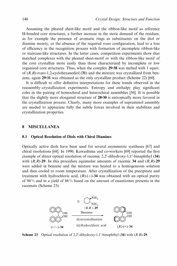
Assuming the pleated sheet-like motif and the ribbon-like motif as reference
H-bonded core structures, a further increase in the steric demand of the residues,
as for example the presence of aromatic rings as substituents on the diol or
diamine moiety, or the absence of the required trans con®guration, lead to a loss
of ef®ciency in the recognition process with formation of incomplete ribbon-like
or staircase-like structures. In the latter cases, competition experiments show that
matched complexes with the pleated sheet-motif or with the ribbon-like motif of
the core crystallize more easily than those characterized by incomplete or low
organized core structures. Thus, when the complex 29�38 was melted with 1 equiv.
of (R,R)-trans-1,2-cyclohexanediol (31) and the mixture was crystallized from ben-
zene, again 29�31 was obtained as the only crystalline product (Scheme 22) [60].
It is dif®cult to offer de®nitive interpretations for these trends observed in the
reassembly±crystallization experiments. Entropy and enthalpy play signi®cant
roles in the pairing of homochiral and heterochiral assemblies [56]. It is possible
that the slightly more elongated structure of 28�30 is entropically more favored in
the crystallization process. Clearly, many more examples of supraminol assembly
are needed to appreciate fully the subtle forces involved in their stabilities and
crystallization properties.
8 MISCELLANEA
8.1 Optical Resolution of Diols with Chiral Diamines
Optically active diols have been used for several asymmetric syntheses [67] and
chiral resolutions [68]. In 1990, Kawashima and co-workers [69] reported the ®rst
example of direct optical resolution of racemic 2,20-dihydroxy-1,10-binaphthyl (34)
with (R,R)-29. In this procedure equimolar amounts of racemic 34 and (R,R)-29
were added in benzene and the mixture was heated to a homogeneous solution
and then cooled to room temperature. After crystallization of the precipitate and
treatment with hydrochloric acid, (R)-(�)-34 was obtained with an optical purity
of 94 % and in a yield of 86 % based on the amount of enantiomer presents in the
racemate (Scheme 23).
OH
i)
ii)
iii)
recrystallization
Benzene
Hydrochloric acid
OH
(+/− )-34 (R )-(+)-34
OHOH
NH2
NH2(R,R)-29
Scheme 23 Optical resolution of 2,20-dihydroxy-1,10-binaphthyl (34) with (R,R)-29.
140 Crystal Design: Structure and Function
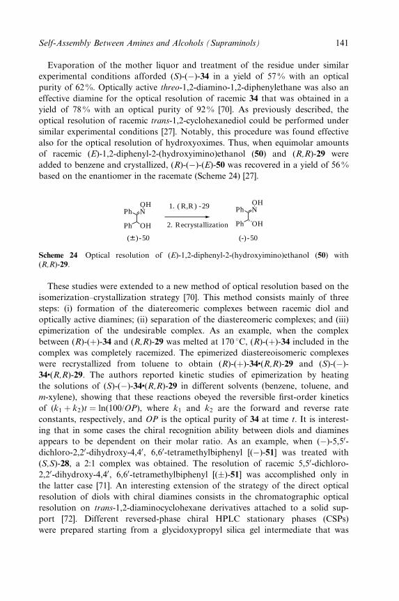
Evaporation of the mother liquor and treatment of the residue under similar
experimental conditions afforded (S)-(ÿ)-34 in a yield of 57% with an optical
purity of 62 %. Optically active threo-1,2-diamino-1,2-diphenylethane was also an
effective diamine for the optical resolution of racemic 34 that was obtained in a
yield of 78% with an optical purity of 92% [70]. As previously described, the
optical resolution of racemic trans-1,2-cyclohexanediol could be performed under
similar experimental conditions [27]. Notably, this procedure was found effective
also for the optical resolution of hydroxyoximes. Thus, when equimolar amounts
of racemic (E)-1,2-diphenyl-2-(hydroxyimino)ethanol (50) and (R,R)-29 were
added to benzene and crystallized, (R)-(ÿ)-(E)-50 was recovered in a yield of 56%
based on the enantiomer in the racemate (Scheme 24) [27].
Ph
Ph OH
OHN Ph
Ph OH
OHN
2. Recrystallization
1. ( R,R ) -29
(6) -50 (-)-50
Scheme 24 Optical resolution of (E)-1,2-diphenyl-2-(hydroxyimino)ethanol (50) with(R,R)-29.
These studies were extended to a new method of optical resolution based on the
isomerization±crystallization strategy [70]. This method consists mainly of three
steps: (i) formation of the diatereomeric complexes between racemic diol and
optically active diamines; (ii) separation of the diastereomeric complexes; and (iii)
epimerization of the undesirable complex. As an example, when the complex
between (R)-(�)-34 and (R,R)-29 was melted at 170 8C, (R)-(�)-34 included in the
complex was completely racemized. The epimerized diastereoisomeric complexes
were recrystallized from toluene to obtain (R)-(�)-34�(R,R)-29 and (S)-(ÿ)-
34�(R,R)-29. The authors reported kinetic studies of epimerization by heating
the solutions of (S)-(ÿ)-34�(R,R)-29 in different solvents (benzene, toluene, and
m-xylene), showing that these reactions obeyed the reversible ®rst-order kinetics
of (k1 � k2)t � ln(100/OP), where k1 and k2 are the forward and reverse rate
constants, respectively, and OP is the optical purity of 34 at time t. It is interest-
ing that in some cases the chiral recognition ability between diols and diamines
appears to be dependent on their molar ratio. As an example, when (ÿ)-5,50-dichloro-2,20-dihydroxy-4,40, 6,60-tetramethylbiphenyl [(ÿ)-51] was treated with
(S,S)-28, a 2:1 complex was obtained. The resolution of racemic 5,50-dichloro-
2,20-dihydroxy-4,40, 6,60-tetramethylbiphenyl [(�)-51] was accomplished only in
the latter case [71]. An interesting extension of the strategy of the direct optical
resolution of diols with chiral diamines consists in the chromatographic optical
resolution on trans-1,2-diaminocyclohexane derivatives attached to a solid sup-
port [72]. Different reversed-phase chiral HPLC stationary phases (CSPs)
were prepared starting from a glycidoxypropyl silica gel intermediate that was
Self-Assembly Between Amines and Alcohols (Supraminols) 141
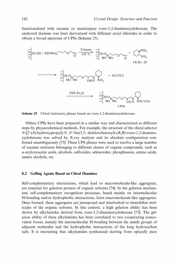
functionalized with racemic or enantiopure trans-1,2-diaminocyclohexane. The
anchored diamine was later derivatized with different aroyl chlorides in order to
obtain a broad spectrum of CPSs (Scheme 25).
Si.OH Si.OSiMe Me
OO
OO
Si(OMe)3+ +NH2
NH2
Si.OSiMe Me
OOH NH2
NH
Si.OSiMe Me
O
CPSsOX NHCOAr
NX
+ ArCOCI
Toluene
110 8C
THF/Et3N
( R,R) -29
Scheme 25 Chiral stationary phases based on trans-1,2-diaminocyclohexane.
Others CPSs have been prepared in a similar way and characterized at different
steps by physicochemical methods. For example, the structure of the chiral selector
N-[20-(S)-hydroxypropyl]-N, N 0-bis(3,5- dichlorobenzoyl)-(R,R)-trans-1,2-diamino-
cyclohexane was solved by X-ray analysis and its absolute con®guration con-
®rmed unambiguously [73]. These CPS phases were used to resolve a large number
of racemic mixtures belonging to different classes of organic compounds, such as
a-aryloxyacetic acids, alcohols, sulfoxides, selenoxides, phosphinates, amino acids,
amino alcohols, etc.
8.2 Gelling Agents Based on Chiral Diamines
Self-complementary interactions, which lead to macromolecule-like aggregates,
are essential for gelation process of organic solvents [74]. In the gelation mechan-
ism, self-complementary recognition processes, based mainly on intermolecular
H-bonding and/or hydrophobic interactions, form macromolecule-like aggregates.
Once formed, these aggregates are juxtaposed and interlocked to immobilize mol-
ecules of the organic solvents. In this context, a high gelation ability has been
shown by alkylamides derived from trans-1,2-diaminocyclohexane [75]. The gel-
ation ability of these alkylamides has been correlated to two cooperating nonco-
valent forces, namely the intermolecular H-bonding between the amide groups of
adjacent molecules and the hydrophobic interactions of the long hydrocarbon
tails. It is interesting that alkylamides synthesized starting from optically pure
142 Crystal Design: Structure and Function
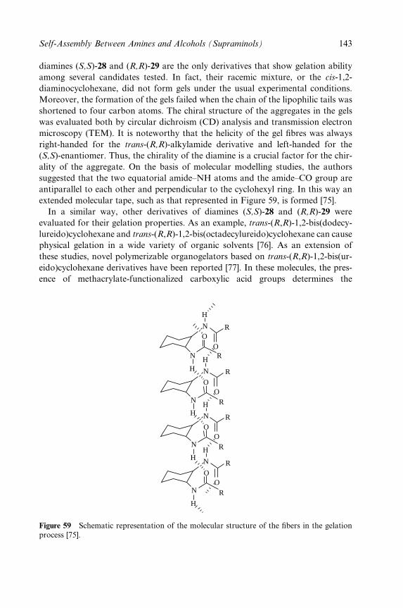
diamines (S,S)-28 and (R,R)-29 are the only derivatives that show gelation ability
among several candidates tested. In fact, their racemic mixture, or the cis-1,2-
diaminocyclohexane, did not form gels under the usual experimental conditions.
Moreover, the formation of the gels failed when the chain of the lipophilic tails was
shortened to four carbon atoms. The chiral structure of the aggregates in the gels
was evaluated both by circular dichroism (CD) analysis and transmission electron
microscopy (TEM). It is noteworthy that the helicity of the gel ®bres was always
right-handed for the trans-(R,R)-alkylamide derivative and left-handed for the
(S,S)-enantiomer. Thus, the chirality of the diamine is a crucial factor for the chir-
ality of the aggregate. On the basis of molecular modelling studies, the authors
suggested that the two equatorial amide±NH atoms and the amide±CO group are
antiparallel to each other and perpendicular to the cyclohexyl ring. In this way an
extended molecular tape, such as that represented in Figure 59, is formed [75].
In a similar way, other derivatives of diamines (S,S)-28 and (R,R)-29 were
evaluated for their gelation properties. As an example, trans-(R,R)-1,2-bis(dodecy-
lureido)cyclohexane and trans-(R,R)-1,2-bis(octadecylureido)cyclohexane can cause
physical gelation in a wide variety of organic solvents [76]. As an extension of
these studies, novel polymerizable organogelators based on trans-(R,R)-1,2-bis(ur-
eido)cyclohexane derivatives have been reported [77]. In these molecules, the pres-
ence of methacrylate-functionalized carboxylic acid groups determines the
H
HH
N
N
N
OO
R
R
HH
N
N
OO
R
R
HH
N
N
OO
R
R
H
N
OO
R
R
Figure 59 Schematic representation of the molecular structure of the ®bers in the gelationprocess [75].
Self-Assembly Between Amines and Alcohols (Supraminols) 143
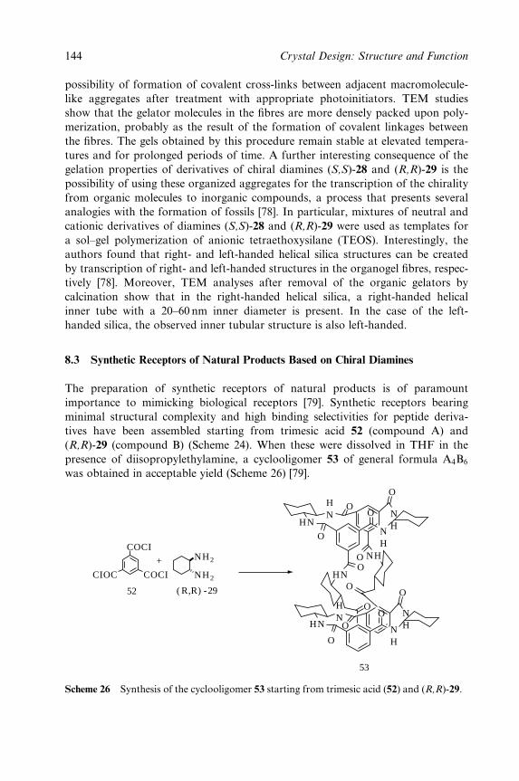
possibility of formation of covalent cross-links between adjacent macromolecule-
like aggregates after treatment with appropriate photoinitiators. TEM studies
show that the gelator molecules in the ®bres are more densely packed upon poly-
merization, probably as the result of the formation of covalent linkages between
the ®bres. The gels obtained by this procedure remain stable at elevated tempera-
tures and for prolonged periods of time. A further interesting consequence of the
gelation properties of derivatives of chiral diamines (S,S)-28 and (R,R)-29 is the
possibility of using these organized aggregates for the transcription of the chirality
from organic molecules to inorganic compounds, a process that presents several
analogies with the formation of fossils [78]. In particular, mixtures of neutral and
cationic derivatives of diamines (S,S)-28 and (R,R)-29 were used as templates for
a sol±gel polymerization of anionic tetraethoxysilane (TEOS). Interestingly, the
authors found that right- and left-handed helical silica structures can be created
by transcription of right- and left-handed structures in the organogel ®bres, respec-
tively [78]. Moreover, TEM analyses after removal of the organic gelators by
calcination show that in the right-handed helical silica, a right-handed helical
inner tube with a 20±60 nm inner diameter is present. In the case of the left-
handed silica, the observed inner tubular structure is also left-handed.
8.3 Synthetic Receptors of Natural Products Based on Chiral Diamines
The preparation of synthetic receptors of natural products is of paramount
importance to mimicking biological receptors [79]. Synthetic receptors bearing
minimal structural complexity and high binding selectivities for peptide deriva-
tives have been assembled starting from trimesic acid 52 (compound A) and
(R,R)-29 (compound B) (Scheme 24). When these were dissolved in THF in the
presence of diisopropylethylamine, a cyclooligomer 53 of general formula A4B6
was obtained in acceptable yield (Scheme 26) [79].
HN
O
OO
OO
O
O
O
OO
HN
HN
O
NH
NHN
H
HN
NH
O
NH
HN
53
CIOC
COCI
COCI
NH2
NH2
+
52 ( R,R) -29
Scheme 26 Synthesis of the cyclooligomer 53 starting from trimesic acid (52) and (R,R)-29.
144 Crystal Design: Structure and Function
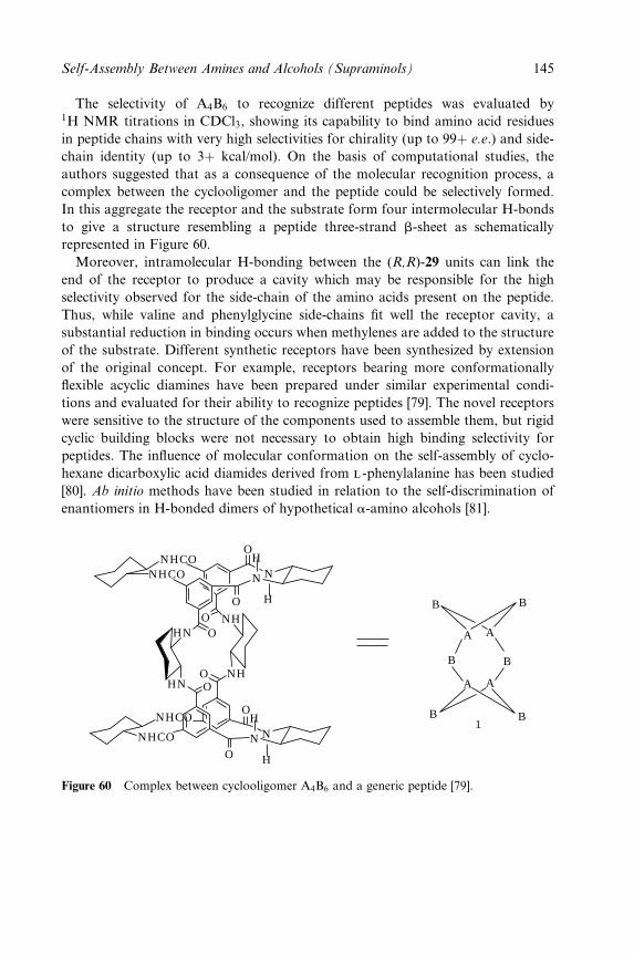
The selectivity of A4B6 to recognize different peptides was evaluated by1H NMR titrations in CDCl3, showing its capability to bind amino acid residues
in peptide chains with very high selectivities for chirality (up to 99� e.e.) and side-
chain identity (up to 3� kcal/mol). On the basis of computational studies, the
authors suggested that as a consequence of the molecular recognition process, a
complex between the cyclooligomer and the peptide could be selectively formed.
In this aggregate the receptor and the substrate form four intermolecular H-bonds
to give a structure resembling a peptide three-strand b-sheet as schematically
represented in Figure 60.
Moreover, intramolecular H-bonding between the (R,R)-29 units can link the
end of the receptor to produce a cavity which may be responsible for the high
selectivity observed for the side-chain of the amino acids present on the peptide.
Thus, while valine and phenylglycine side-chains ®t well the receptor cavity, a
substantial reduction in binding occurs when methylenes are added to the structure
of the substrate. Different synthetic receptors have been synthesized by extension
of the original concept. For example, receptors bearing more conformationally
¯exible acyclic diamines have been prepared under similar experimental condi-
tions and evaluated for their ability to recognize peptides [79]. The novel receptors
were sensitive to the structure of the components used to assemble them, but rigid
cyclic building blocks were not necessary to obtain high binding selectivity for
peptides. The in¯uence of molecular conformation on the self-assembly of cyclo-
hexane dicarboxylic acid diamides derived from l -phenylalanine has been studied
[80]. Ab initio methods have been studied in relation to the self-discrimination of
enantiomers in H-bonded dimers of hypothetical a-amino alcohols [81].
HN
HN
NH
NH
NHCO
NHCO
O
OO
O
O
O
H
H
H
H
N N
NN
OO
NHCO
NHCO
B
B
B
B
BB
A A
AA
1
Figure 60 Complex between cyclooligomer A4B6 and a generic peptide [79].
Self-Assembly Between Amines and Alcohols (Supraminols) 145
9 CONCLUSION
H-bonding between amide-type NH and carbonyl-type O atoms has been known
ever since the ®rst insights into secondary and tertiary structures of proteins and
polypeptides. This type of H-bonding can engage only two atom types and is one-
dimensional. H-bonding between an amine and an alcohol, on the other hand,
can take full advantage of the donor±acceptor characteristics of each group,
resulting in a possible tetrahedral geometry. Thus, in ideal cases all hydrogens
and lone pairs of an amine and an alcohol can engage in inter- or intramolecular
H-bonding to produce two- and three-dimensional arrays of polyamines, polyal-
cohols, and, more interestingly, polyamino alcohols. Complexes between organic
amines and alcohols have been known in solution and in the solid state for many
years. Depending on the structures of the amines and alcohols, different supramo-
lecular architectures are possible, and many have been characterized by X-ray
analysis, revealing intriguing analogies with the structures of inorganic and
organic lattices.
When the component amines and alcohols incorporate elements of chirality and
symmetry, the resulting complexes are assembled by H-bonding through recogni-
tion, complementarity, and favourable organization to give three-dimensional
supramolecular structures. These `supraminols' can assemble in ordered right- or
left-handed helical structures where NH and OH groups can be fully or partially
coordinated (H-bonded). In this regard, trans-1,2-diaminocyclohexane is an excep-
tional supramolecular chiron or `assembler' of supraminols in conjunction with
complementary alcohols and diols. The recognition process can be extended to
optical resolution and the design of arti®cial receptors of small molecules.
Because of the weaker nature of the H-bonds between amines and alcohols,
compared with more polar amidic H-bonds, supraminols are compatible with
hydrophobic environments when crystallized, although this is not a requirement.
The supraminol helical trans-1,2-diaminocyclohexane±CO2 complex can be recrys-
tallized from aqueous ethanol [51].
Intra- and intermolecular H-bonding is well documented for small organic
molecules, even if super-architectures are not involved [30]. We are not aware of
examples H-bonding between an amino or alcohol group of a small organic mol-
ecule with complementary similar groups in the active site of an enzyme. For
example, an H-bond between the C-200 hydroxyl group in the aminoglycoside antibi-
otic paromomycin and a cytidine unit 1407 in 16S ribosomal RNA has been inferred
from NMR studies [82] and X-ray crystallography [83]. We are also unaware of
H-bonding between amino and hydroxyl groups of amino acids with proteins (as for
example a serine OH and a lysine NH2). Even if they existed, such H-bonds would be
much weaker than amide types.
As for the supraminols and related superstructures covered in this chapter,
entropic and enthalpic forces may combine with steric factors, recognition, and
complementarity to ultimately decide the architecture, organization, dimensional-
146 Crystal Design: Structure and Function
ity, and, in human visual terms, the aesthetic quality of the resulting motif. In
contrast to normal disconnective analysis in the synthesis planning of a complex
organic molecule, where simpler building blocks can be deduced, then chemically
assembled to give the intended target, the assembly of amines and alcohols by
H-bonding to give supraminols to superstructures of predictable shapes and archi-
tectures in the solid state is still a challenging goal.
ACKNOWLEDGEMENTS
We thank Eric Therrien for the skillful art work and Dr Michel Simard for the
X-ray analyses.
REFERENCES
1. For selected references, see for example: (a) Khazanovich, N.; Granja, R. J.; McRee, D.E.; Milligan, R. A.; Ghadiri, M. R. J. Am. Chem. Soc. 1994, 116, 6011. (b) Mathias, J.P. ; Simanek, E. E.; Whitesides, G. M. J. Am. Chem. Soc. 1994, 116, 4316. (c) Yang, J.;Marendaz, J.; Geib, L. S. J.; Hamilton, A. D. Tetrahedron Lett. 1994, 35, 3665. (d)Chang, Y.; West, M.; Fowler, F. W.; Lauher, J. W. J. Am. Chem. Soc. 1993, 115, 5991.(e) Lehn, J.-M.; Mascal, M.; DeCian, A.; Fisher, J. J. Chem. Soc., Perkin Trans. 2 1992,461. (f) Simard, M.; Su, D.; Wuest, J. D. J. Am. Chem. Soc. 1991, 113, 4696. (g) Forreferences to crystallographic studies, see: Taylor, R.; Kennard, O. Acc. Chem. Res.1984, 17, 320.
2. For selected references, see for example: (a) Chin, D. N.; Zerkowski, J. A.; McDonald, J.C.; Whitesides, G. M. In Organised Molecular Assemblies in the Solid State; Whitesell, J.K., Ed.; Wiley, Chichester, 1999, p. 185. (b) Reichert, A.; Ringsdorf, H.; Schumacher,P.; Baumeister, W.; Scheybani, T. In Comprehensive Supramolecular Chemistry; Atwood,J. L.; Davies, J. E. D.; McNicol, D. D.; Vogtel, F., Eds; Pergamon Press, Oxford, Vol. 9,1996, p. 313. (c) Fredericks, J. R.; Hamilton, A. D. In Comprehensive Supramolecular
Chemistry; Atwood, J. L.; Davies, J. E. D.; McNicol, D. D.; VoÈgtle, F., Eds; PergamonPress, Oxford, Vol. 9, 1996, p. 565. (d) Lawrence, D. S.; Jiang, T.; Levett, M. Chem.
Rev. 1995, 95, 2229. (e) Subramanian, S.; Zaworotko, M. J. J. Coord. Chem. Rev. 1994,137, 357. (e) Aakeroy, C. B.; Seddon, K. R. Chem. Soc. Rev. 1993, 22, 397. (f) Lehn, J.-M. Angew. Chem., Int. Ed. Engl. 1990, 29, 1304. (g) Lehn, J.-M. Angew. Chem., Int. Ed.
Engl. 1988, 27, 89. (h) VoÈgtle, F. Supramolecular Chemistry; Wiley, Chichester, 1991.3. For selected references see for example: (a) Aakeroy, C. B.; Borovik, A. S., Eds; Coord-
ination Chemistry Reviews; Elsevier, Amsterdam, Vol. 183, 1999. (b) Weber, E., Ed.;Design of Organic Solids, Topics in Current Chemistry; Springer, Berlin, Vol. 198, 1998.(c) Fredericks, J. R, Hamilton, A. D. In Comprehensive Supramolecular Chemistry;Atwood, J. L.; Davies, J. E. D.; McNicol, D. D.; Vogtle, F., Eds; Pergamon Press,Oxford, Vols 6, 7, 9, and 10, 1996. (d) Desiraju, G. R.; Sharma, C. V. K., in Perspectives
in Supramolecular Chemistry; Desiraju, G. R., Ed., Wiley, Chichester, Vol. 2, p. 31, 1995.(e) Dunitz, J. D. in Perspectives in Supramolecular Chemistry; Desiraju, G. R., Ed.,Wiley, Chichester, Vol. 2, p. 1, 1995. (f) Desiraju, G. R., Crystal Engineering: The Design
of Organic Solids; Elsevier, Amsterdam, 1989. (g) Mascal, M. Contemp. Org. Synth.1994, 1, 31.
Self-Assembly Between Amines and Alcohols (Supraminols) 147
4. (a) Guru Row, T. N. Coord Chem. Rev. 1999, 183, 81. (b) Russel, VA. ; Ward, M. D.Chem. Mater. 1996, 8, 1654. (c) Blanchard-Desce, M. In Comprehensive Supramolecular
Chemistry; Atwood, J. L.; Davies, J. E. D.; McNicol, D. D.; Vogtle, F., Eds; PergamonPress, Oxford, Vol. 10, 1996, p. 833.
5. (a) Kaes, C.; Hosseini, M. W.; Rickard, C. E. F.; Skelton, B. W.; White, A. H. Angew.
Chem., Int. Ed. Engl. 1998, 7, 920;6. Di Salvo, F. J. Science 1990, 247, 649.7. (a) Felix, O.; Hosseini, M. W.; De Cian, A.; Fischer, J. Angew. Chem., Int. Ed. Engl.
1997, 36, 102, and references cited therein. (b) See also Ref. 1f.8. Zhao, X.; Chang, Y.-L.; Fowler, F. W.; Lauher, J. W. J. Am. Chem. Soc. 1990, 112,
6627.9. Kimbara, C. K.; Hashimoto, Y., Sukewaga, M., Nohira, H.; Saigo, K. J. Am. Chem.
Soc. 1996, 118, 3441.10. Zerkowski, D. J. A.; Seto, C.; Wierda, D. A.; Whitesides, G. M. J. Am. Chem. Soc.
1990, 112, 9025.11. (a) See as examples of helical aggregates: Geib, S. J.; Vincent, C.; Fan, E.; Hamilton, A.
D. Angew. Chem., Int. Ed. Engl. 1993, 32, 119. (b) Sanchez-Quesada, J.; Seel, C.;Pradas, P.; De Mendoza, J. J. Am. Chem. Soc. 1996, 118, 277. (c) Koshima, S.; Honke,S. J. Org. Chem. 1999, 64, 790.
12. Stockman, P. A., Bumgarner, R. E., Suzuki, S.; Blake, G. A. J. Chem. Phys. 1992, 96,2496.
13. Tubergen, M. J.; Kuczwoski, R. L. J. Am. Chem. Soc. 1993, 115, 9263.14. Barry, A. J.; Peterson, F. C.; King, A. J. J. Am. Chem. Soc. 1936, 58, 333.15. Davis, W. E.; Barry, A. J.; Peterson, F. C.; King, A. J. J. Am. Chem. Soc. 1943, 65,
1294.16. (a) Creely, J. J.; Wade, R. H. J. Polym. Sci., Polym. Lett. Ed. 1978, 16, 291.
(b) Henrissat, B.; Marchessault, R. H.; Taylor, M. G.; Chanzy, H. Polym. Commun.1987, 28, 113.
17. Trogus, C.; Hess, K. Z. Phys. Chem. 1931, B14, 387.18. Lee, D. M.; Burn®eld, K. E.; Blackwell, J. J. Biopolymers 1972, 11, 89.19. Kiyoshi, T.; Katsuo, M.; Shinsuke, Y. J. Phys. Chem. B 1999, 103, 3457.20. Lewinski, J.; Zachara, J.; Kopec, T., Starawiesky, B. K.; Lipkowski, J.; Justyniak, I.;
Kolodziejczyk. E. Eur. J. Inorg. Chem. 2001, 5, 1123.21. For selected references on predictions of crystal structures, see: (a) Perlstein, J. J. Am.
Chem. Soc. 1994, 116, 455. (b) Perlstein, J. J. Am. Chem. Soc. 1992, 114, 1955. (c)Gavezzotti, A. J. Am. Chem. Soc. 1991, 113, 4622. (d) Gavezzotti, A. Acc. Chem. Res.1994, 27, 309. (e) Maddox, J. Nature 1988, 335, 201. (f) Leiserowitz, E.; Hagler, A. T.Proc. R. Soc. London, Ser. A 1983, 388, 133. (g) Curtin, D. Y.; Paul, I. C. Chem. Rev.1981, 81, 525.
22. See for example: (a) Edlund, U.; Holloway, C.; Levy, G. C. J. Am. Chem. Soc. 1976,98, 5069. (b) Joesten, M. D.; Schaad, L. J., Eds; Hydrogen Bonding; Marcel Dekker,New York, 1974.
23. See, for example: Pirkle, W. H.; Pochapsky, T.-C. Chem. Rev. 1989, 89, 347. (b) Weis-man, G. R. In Asymmetric Synthesis; Morrison, J. D., Ed.; Academic Press, New York,Vol. 1, 1983, p. 153.
24. Baker, J. W.; Davies, M. M.; Gaunt, J. J. Chem. Soc. 1949, 24.25. Stevenson, D. P. J. Am. Chem. Soc. 1962, 84, 2849.26. Saikia, B.; Suryanarayana, I.; Saikia, B. H.; Haque, I. Spectrochim. Acta, Part A 1991,
47, 791.27. Kawashima, M.; Hirayama, A. Chem. Lett., 1991, 763.28. Ermer, O.; Eling, A. J. Chem. Soc., Perkin Trans 2 1994, 925.
AQ3
AQ4
148 Crystal Design: Structure and Function
29. (a) Ko¯er, A. In Landolt±Bornstein, Zahlenwerte und Funktionen aus Physik, Chemie,
Astronomie, Geophysic und Technik, 6th edn; Schafer, K.; Lax, E., Eds; Springer, Berlin,Vol.2, Part 3, 1956, p. 350. (b) Moelwyn-Hughes, E. A. Physical Chemistry, 2nd edn;Pergamon Press, Oxford, 1964, p. 1060.
30. For examples of intermolecular H-bonding in small organic molecules, see the followingCambridge Crystallographic Data base codes: a, aromatic amino alcohols, ACBUET,BADWUX, CAGMAX, FLCTRT, IPAXP, KOSIR, MHPEAM, VANKIE, XEJLUT,BVJAJ; b, cyclic hydrocarbons, cyclitols, indanes, bicyclic compounds, steroids, BOL-SOK, CBTANP, DENBIH, DOCINA, QEZSET, LATCOY, SUVNIG, WAZDEG,XESRES, TODCOE, TAYWOF, EIMCHO, EPICHO, QUDDUO; c, nucleosides,AMICET, BURNUX, COMBOV; d, amino acids, AETHRE, HIBUJ, WIRMIT; e,heterocycles, DAQYAV, HIWYIV, JUNDUL, JUNDOR. For examples of intramo-lecular H-bonding: a, azaspiro compound, BODKEK; b, amino sugar, BEHPOT; c,steroid, ERALK10, EPCHOL; d, piperidine, EPINUP; e, pyrrolidine, ZOGNAK; f,kanamaycin sulfate, KNMSYL; g, azithromycin, SAHWAZ; h, erythronocyclamine c,CUHPUQ10.
31. Brown, C. J. Acta Crystallogr. 1951, 4, 100.32. Liminga R. and Olovsson, I. Acta Crystallogr. 1964, 17, 1523.33. Liminga, R. Acta Chem. Scand. 1967, 21, 1206.34. Corcoran, J. M.; Kruse, H. W.; Skolnik, S. J. Phys. Chem. 1953, 57, 435.35. Allen, F. H.; Hoy, V. J.; Howard, J. A. K.; Thalladi, V. R., Desiraju, G. R., Wilson, C.
C.; McIntyre, G. J. J. Am. Chem. Soc. 1997, 119, 3477.36. (a) Robertson, J. M. Proc. R. Soc. London Ser. A 1951, 207, 101. (b) Desiraju, G. R.;
Gavezzotti, A. Acta Crystallogr. 1989, B45, 473.37. Rusek, G.; Mazurek, J.; Lis, T.; Krajewski, K. Pol. J. Chem. 1997, 71, 119.38. Mootz, D.; Brodalla, D.; Wiebcke, M. Acta Crystallogr. 1989, C45, 754.39. Meyers, E. A.; Lipscomb, W. N. Acta Crystallogr. 1955, C8, 583.40. Donohue, J. Acta Crystallogr. 1958, C11, 512.41. Toda, F.; Hyoda, S.; Okada, K.; Hirotsu, K. J. Chem. Soc., Chem. Commun. 1995,
1531.42. Goldberg, I.; Stein, Z.; Kai, A.; Toda, F. Chem. Lett. 1987, 1617.43. Toda, F.; Tanaka, K.; Hyoda, T.; Mak, T. C. W., Chem. Lett. 1988, 107.44. Loehlin, J. H.; Franz, K. J.; Gist, L.; Moore, R. H. Acta Crystallogr. 1998, B54, 695.45. (a) Etter, M. C. Acc. Chem. Res. 1990, 23, 120. (b) Etter, M. C.; MacDonald, J. C.;
Bernstein, J. Acta Crystallogr. 1990, B46, 256.46. Bernstein, J.; Davis, R. E.; Shimoni, L.; Chang, N.-L. Angew. Chem., Int. Ed. Engl.
1995, 34, 1555.47. Desiraju, G. R. Crystal Engineering, The Design of Organic Solids; Elsevier, New York,
1989, chapt. 6, p. 175.48. O'Leary, B.; Spalding, T. R.; Ferguson, G.; Glidewell, C. Acta Crystallogr. 2000, B56,
273.49. Jaunky, V.; Hosseini, M. W.; Planeix, J. M.; Cian, A. D.; Kyritsakas, N.; Fischer, J. J.
Chem. Soc., Chem. Commun. 1999, 2313.50. Hanessian, S.; Gomtsyan, A.; Simard, M.; Roelens, S. J. Am. Chem. Soc. 1994, 116,
4495.51. Hanessian, S.; Simard, M.; Roelens, S. J. Am. Chem. Soc. 1995, 117, 7630.52. For references on the preparation of enantiomerically pure trans-1,2-diamines, see: (a)
Scaros, M. G.; Yonan, P. K.; Laneman, S. A.; Fernando, P. N. Tetrahedron: Asym-
metry 1997, 8, 1501. (b) Chooi, S. Y. M.; Leung, P.-H. ; Ng S.-C., Quek, G. H.; Sim,K. Y. Tetrahedron: Asymmetry 1991, 2, 981; (c) Onuma, K. ; Ito, T.; Nakamura, A.Bull. Chem. Soc. Jpn. 1984, 53, 2012. (d) Galsbùl, F.; Steenbùl, P.; Sùndergaard, G.;
Self-Assembly Between Amines and Alcohols (Supraminols) 149
Sùrensen, S. B. Acta Chem. Scand. 1972, 26, 3605. (e) Asperger, R. G.; Liu, C. F.Inorg. Chem. 1965, 4, 1492. (f) Jaeger, F. M.; Bijkerk, L. Z. Anorg. Allg. Chem. 1937,97, 233.
53. Hanessian, S., Meffre, P.; Girard, M.; Beaudoin, S.; SanceÂau, J.-Y.; Benanni, Y. J. Org.
Chem. 1993, 58, 1991.54. (a) For a review, see Hanessian, S.; Bennani, Y. Chem. Rev. 1997, 97, 3161. (b) Hanes-
sian, S.; Gomtsyan, A. Tetrahedron Lett. 1994, 35, 7509. (c) Hanessian, S.; Gomtsyan,A.; Malek, N. J. Org. Chem. 2000, 65, 5623; (d) Hanessian, S.; Gomtsyan, A., Payne,A.; HerveÂ, Y.; Beaudoin, S. J. Org. Chem. 1993, 58, 5032. (e) Hanessian, S.; Benanni,Y.; HerveÁ, Y. Synlett 1993, 35. (d) Hanessian, S.; Beaudoin, S. Tetrahedron Lett. 1992,33, 7655. (f) Hanessian, S.; Beaudoin, S. Tetrahedron Lett. 1992, 33, 7659. (g) Hanes-sian, S.; Benanni, Y. Tetrahedron Lett. 1990, 31, 6465, and previous references. (h)Hanessian, D.; Delorme, D.; Beaudoin, S.; Leblanc, Y. J. Am. Chem. soc. 1984, 106,5754.
55. For studies with vicinal diols, see: Huang, C.; Cabell, L. A.; Anslyn, E. V. J. Am.
Chem. Soc. 1994, 116, 2778. For FT-IR studies on hydrogen bonding, see for example:Dado, G. P., Gellman, S. H. J. Am. Chem. Soc. 1993, 115, 4228. For reviews of the useof IR spectra in connection with hydrogen bonding interactions, see for example: (a)Symons, M. C. R. Chem. Soc. Rev. 1983, 12, 1. (b) Aaron, H. S. Top. Stereochem.1979, 11, 1.
56. Hunenberg, P. H.; Granwehr, J. K.; Aebischer, J.-N.; Ghoneim, N.; Haselbach, E.; vanGunsteren, W. F. J. Am. Chem. Soc. 1997, 119, 7533.
57. Scott, W. R. P., van Gunsteren, W. F. In Methods in Computational Chemistry:
METECC-95, Clementi, E.; Corongiu, G., Eds; STEF, Cagliari, 1995, p. 397.58. For another example of applications of microcalorimetric methods to complexes with
similar structure, see: Haselbach, E.; Ghoneim, N.; Aebischer, J.-N. Progress Reports,Chiral 2±Workshops of the Swiss National Science Foundation, 1994, 1995.
59. Suemune, H.; Hasegawa, A.; Sakai, K. Tetrahedron: Asymmetry 1995, 6, 55.60. Hanessian, S., Saladino, R.; Margarita, R.; Simard, M. Chem. Eur. J. 1999, 5, 2169.61. Roelens, S.; Dapporto, P.; Paoli, P. Can. J. Chem. 2000, 78, 723.62. For examples of synthesis of carbamate salts, see: (a) Von Dreele, R. B.; Bradshaw, R.
L.; Burke, W. Acta Crystallogr. 1983, C39, 253. (b) Adams, J. M.; Small, R. W. H. J.
Acta Crystallogr. 1973, B29, 2317. (c) Braibanti, A.; Manotti Lanfredi, M. L.; Pellin-ghelli, M. A; Tiripicchio, A. Acta Crystallogr. 1971, B27, 2248, 2261.
63. Dapporto, P.; Paoli, P.; Roelens, S. J. Org. Chem. 2001, 66, 4930.64. (a) Hanessian, S.; Nunez, J. C. unpublished data. (b) Hanessian, S.; Gauthier, J.-Y.;
Okamoto, K.; Beauchamp, A. L.; Theophanides, T. Can. J. Chem. 1993, 71, 880.65. Desiraju, G. R. Angew. Chem., Int. Ed. Engl. 1995, 34, 2311.66. For references about the chiron concept, see: (a) Hanessian, S. In Total Synthesis of
Natural Products: The Chiron Approach; Pergamon Press, New York, 1983. (b) Nangia,A.; Desiraju, G. R. Topics in Current Chemistry; Springer, Berlin, Vol. 198, 1998. (c)Nangia, A. Curr. Sci. 2000, 78, 374.
67. See, for example: (a) Seebach, D.; Beck, A. K.; Roggo, S.; Wonnacott, A. Chem. Ber.1985, 118, 3673. (b) Trost, B. M., Murphy, D. J. Organometallics 1985, 4, 1143.
68. See, for example: (a) Kassai, C.; Juvancz, Z.; Balint, J.; Fogassy, E.; Kozma, D. Tetra-
hedron 2000, 56, 8355. (b) Gong, B.-Q.; Chen, W.-Y.; Hu, B.-F. J. Org. Chem. 1991, 56,423. (c) Tamai, Y.; Heung-Cho, P.; Iizuka, K.; Okamura, A.; Miyano, S. Synthesis
1990, 222. (d) Jacques, J.; Fouquey, C. Org. Synth. 1988, 67, 1. (e) Truesdale, L. K.Org. Synth. 1988, 67, 13. (f) Toda, F.; Tanaka, K. J. Org. Chem. 1988, 53, 3607. (g)Brussee, J.; Groenedijik, J. L. G.; Koppele, J. M.; Jansen, A. C. A. Tetrahedron 1985,41, 3313.
150 Crystal Design: Structure and Function
69. (a) Kawashima, M.; Hirata, R. Bull. Chem. Soc. Jpn. 1993, 66, 2002. (b) Kawashima,M.; Hirayama. A., Chem. Lett. 1990, 2299.
70. Saigo, K.; Kubota, N.; Takebayashi, S.; Hasegawa, M. Bull. Chem. Soc. Jpn. 1986, 59,931.
71. Tanaka, K.; Moriyama, A:, Toda, F. J. Org. Chem. 1997, 62, 1192.72. (a) Sinibaldi, M.; Carunchio, V.; Corradini, C.; Girelli, A. M. Chromatographia 1984,
18, 459. (b) Gasparrini, F.; Misiti, D.; Villani, C. Chirality 1992, 4, 447.73. Cirilli, R.; Gasparrini, F.; Villani, C.; Gavuzzo, E.; Cirilli, M. Acta Crystallogr. 1997,
C53, 1937.74. (a) Hanabusa, K.; Matsumoto, Y.; Miki, T.; Koyama, T.; Shirai, H. J. Chem. Soc.,
Chem. Commun. 1994, 1401. (b) Hanbusa, K.; Naka, Y.; Koyama, T.; Shirai, H. J.
Chem. Soc., Chem. Commun. 1994, 2683. (c) Jokic, M.; Makarevic, J.; Zinic, M. J.
Chem. Soc., Chem. Commun. 1995, 1723. (d) Stocks, H. T.; Turner, N. J.; McCague, R.J. Chem. Soc., Chem. Commun. 1995, 585.
75. Hanabusa, K.; Yamada, M.; Kimura, M.; Shirai, H. Angew. Chem., Int, Ed. Engl. 1996,35, 1949.
76. Hanabusa, K.; Shimura, K.; Hirose, K.; Kimura, M.; Shirai, H. Chem. Lett. 1996, 885.77. De Loss, M.; Van Esch, J.; Stokroos, I.; Kellog, R. M.; Feringa, B. L. J. Am. Chem.
Soc. 1997, 119, 12675.78. (a) Jung, J. H.; Ono, Y., Hanabusa, K.; Shinkai, S. J. Am. Chem. Soc. 2000, 122, 5008.
(b) Ono, Y.; Kanekiyo, Y.; Inoue, K.; Hijo, J.; Shinkai, s. Chem. Lett. 1999, 23. (c)Ono, Y.; Nakashima, K.; Sano, M.; Hojo, J.; Shinkai, S. Chem. Lett 1999, 119.
79. (a) Yoon, S. S.; Still, W. C. J. Am. Chem. Soc. 1993, 115, 823. (b) Tetrahedron Lett.1994, 35, 2117.
80. Bergeron, R. J.; Yao, G. Y.; Erdos, G. W.; Milstein, S.; Gao, F.; Rocca, J.; Weimar,W. R.; Price, H. L.; Phanstiel, O., Bioorg. Med. Chem. 1997, 5, 2049.
81. Akorta, I.; Elguero, J. J. Am. Chem. Soc. 2002, 124, 1488.82. (a) Fourmy, D.; Recht, M. I.; Blanchard, S. C.; Puglisi, J. D. Science 1996, 274, 1367.
(b) Blanchard, S. C.; Fourmy, D.; Eason, R. G.; Puglisi, J. D. Biochemistry 1998, 37,7716.
83. Vicens, Q.; Westhof, E. Structure 2001, 9, 647.
Self-Assembly Between Amines and Alcohols (Supraminols) 151
Chapter 3
Very Large SupramolecularCapsules Based on HydrogenBonding
JERRY L. ATWOOD, LEONARD J. BARBOUR, AND AGOSTON JERGA
University of Missouri±Columbia, Columbia, MO, USA
1 INTRODUCTION
An important feature in the evolution of biological systems is the encapsulation of
entities within the con®nes of a structure [1]. Ultimately, the cell presents itself as
a functional example of this enclosure of chemical space [2]. Nature has also used
proteins and polypeptide chains as the building blocks for assemblies which con-
tain and protect guests [3]. The guests may be the nucleic acid of viruses in the
rhinovirus [4], poliovirus [5], cowpea chlorotic mottle virus [6], or the iron-
containing core in the iron storage protein ferritin [7]. Even now, these biological
capsules are beyond the synthetic grasp of the chemist because of the size and
complexity of the enclosure. A further complication which has not often been
addressed in the chemical literature is the very high level of organization found
on the interior of enclosures of biological importance.
The encapsulation of chemical space on the scale of simple molecules has been
a topic of considerable interest for more than two decades. For the formation of
capsules two independent strategies have emerged: covalent synthesis and self-
assembly. The groups of Cram [8], Collet [9], and Sherman [10] have synthesized
capsules capable of encapsulating up to three small molecular guests [11]. Rebek
and co-workers pioneered the use of self-assembly to produce a variety of assem-
blies held together by hydrogen bonds [12±15]. Multi-component systems have
Crystal Design: Structure and Function. Volume 7Edited by Gautam R. Desiraju
Copyright 2003 John Wiley & Sons, Ltd.ISBN: 0-470-84333-0
also been assembled by means of transition metal-based coordinate bonds
[16±21]. The synthesis of three-dimensional hosts capable of containing a wide
variety of guests has been achieved by the use of the principles of crystal engineer-
ing [22,23].
From our viewpoint, self-assembly [24], the single-step construction of molecular
architecture using noncovalent forces, has provided an attractive means for con-
structing large, highly organized chemical entities. Owing to the reversibility of such
interactions, noncovalent bonds, upon selection of appropriate chemical subunits,
can facilitate error-free generation of either discrete or in®nite supramolecular
species.
2 SUPRAMOLECULAR CAPSULES
Typically, synthetic capsules have a contained volume in the range 200±350 ÊA3. In
1997, we discovered a spherical assembly consisting of [(C-methylresorcin[4]arene)6(H2O)8], 1. This assembly, Figure 1, with an enclosed volume of 1375 ÊA3, was
characterized by a single-crystal X-ray diffraction study and was found to be
stable in nonpolar solvents [25]. Supramolecular assembly 1 ultimately led to the
discovery of the link between 1 and the solid geometry principles of Plato and
Archimedes [26]. Before this discussion progresses, it is useful to examine brie¯y
Platonic and Archimedean solids.
The Platonic solids comprise a family of ®ve convex uniform polyhedra (Figure 2,
Table 1) which possess cubic symmetry and are made of the same regular polygons
(equilateral triangle, square, pentagon) arranged in space such that the vertices,
edges, and three coordinate directions of each solid are equivalent. That there is
a ®nite number of such polyhedra is due to the fact that there exists a limited
number of ways in which identical regular polygons may be adjoined to construct a
convex corner. There are thus only ®ve such isometric polyhedra, all of which are
achiral.
In addition to the Platonic solids, there exists a family of 13 convex uniform
polyhedra known as the Archimedean solids. Each member of this family is made
up of at least two different regular polygons and may be derived from at least one
Platonic solid through either truncation or twisting of faces (Figure 3, Table 2). In
the case of the latter, two chiral members, the snub cube and the snub dodecahe-
dron, are realized. The remaining Archimedean solids are achiral.
Returning to the discussion of 1, it was the discovery that members of the
resorcin[4]arene family, 2, self-assemble to form the capsule shown as 1 in Figure
1 that prompted our research group to examine the topologies of related spherical
hosts. Further, we sought to understand existing structures on the basis of sym-
metry. In addition to providing a grounds for classi®cation, it was anticipated
154 Crystal Design: Structure and Function
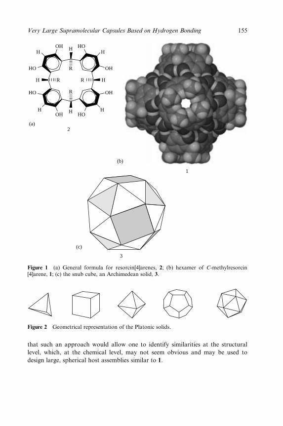
H
HO
HO
HOH
OH
OH
OH
OH
HHH
H
H
H
R
R R
R
HO
(a)
(b)
(c)
2
1
3
Figure 1 (a) General formula for resorcin[4]arenes, 2; (b) hexamer of C-methylresorcin[4]arene, 1; (c) the snub cube, an Archimedean solid, 3.
Figure 2 Geometrical representation of the Platonic solids.
that such an approach would allow one to identify similarities at the structural
level, which, at the chemical level, may not seem obvious and may be used to
design large, spherical host assemblies similar to 1.
Very Large Supramolecular Capsules Based on Hydrogen Bonding 155
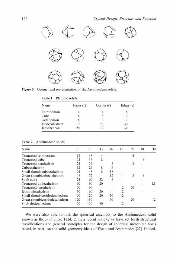
Figure 3 Geometrical representation of the Archimedean solids.
Table 1 Platonic solids.
Name Faces (f ) Corner (c) Edges (e)
Tetrahedron 4 4 6Cube 6 8 12Octahedron 8 6 12Dodecahedron 12 20 30Icosahedron 20 12 30
Table 2 Archimedean solids.
Name c e f3 f4 f5 f6 f8 f10
Truncated tetrahedron 12 18 4 Ð Ð 4 Ð ÐTruncated cube 24 36 8 Ð Ð Ð 6 ÐTruncated octahedron 24 36 Ð 6 Ð 8 Ð ÐCuboctahedron 12 24 8 6 Ð Ð Ð ÐSmall rhombicuboctahedron 24 48 8 18 Ð Ð Ð ÐGreat rhombicuboctahedron 48 72 Ð 12 Ð 8 6 ÐSnub cube 24 60 32 6 Ð Ð Ð ÐTruncated dodecahedron 60 90 20 Ð Ð Ð Ð 12Truncated icosahedron 60 90 Ð Ð 12 20 Ð ÐIcosidodecahedron 30 60 20 Ð 12 Ð Ð ÐSmall rhombicosidodecahedron 60 120 20 30 12 Ð Ð ÐGreat rhombicosidodecahedron 120 180 Ð 30 Ð 20 Ð 12Snub dodecahedron 60 150 80 Ð 12 Ð Ð Ð
We were also able to link the spherical assembly to the Archimedean solid
known as the snub cube, Table 2. In a recent review, we have set forth structural
classi®cations and general principles for the design of spherical molecular hosts
based, in part, on the solid geometry ideas of Plato and Archimedes [27]. Indeed,
156 Crystal Design: Structure and Function
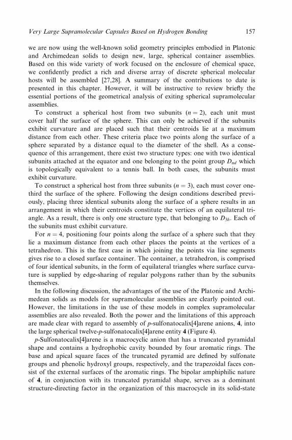
we are now using the well-known solid geometry principles embodied in Platonic
and Archimedean solids to design new, large, spherical container assemblies.
Based on this wide variety of work focused on the enclosure of chemical space,
we con®dently predict a rich and diverse array of discrete spherical molecular
hosts will be assembled [27,28]. A summary of the contributions to date is
presented in this chapter. However, it will be instructive to review brie¯y the
essential portions of the geometrical analysis of exiting spherical supramolecular
assemblies.
To construct a spherical host from two subunits (n � 2), each unit must
cover half the surface of the sphere. This can only be achieved if the subunits
exhibit curvature and are placed such that their centroids lie at a maximum
distance from each other. These criteria place two points along the surface of a
sphere separated by a distance equal to the diameter of the shell. As a conse-
quence of this arrangement, there exist two structure types: one with two identical
subunits attached at the equator and one belonging to the point group Dnd which
is topologically equivalent to a tennis ball. In both cases, the subunits must
exhibit curvature.
To construct a spherical host from three subunits (n � 3), each must cover one-
third the surface of the sphere. Following the design conditions described previ-
ously, placing three identical subunits along the surface of a sphere results in an
arrangement in which their centroids constitute the vertices of an equilateral tri-
angle. As a result, there is only one structure type, that belonging to D3h. Each of
the subunits must exhibit curvature.
For n � 4, positioning four points along the surface of a sphere such that they
lie a maximum distance from each other places the points at the vertices of a
tetrahedron. This is the ®rst case in which joining the points via line segments
gives rise to a closed surface container. The container, a tetrahedron, is comprised
of four identical subunits, in the form of equilateral triangles where surface curva-
ture is supplied by edge-sharing of regular polygons rather than by the subunits
themselves.
In the following discussion, the advantages of the use of the Platonic and Archi-
medean solids as models for supramolecular assemblies are clearly pointed out.
However, the limitations in the use of these models in complex supramolecular
assemblies are also revealed. Both the power and the limitations of this approach
are made clear with regard to assembly of p-sulfonatocalix[4]arene anions, 4, into
the large spherical twelve-p-sulfonatocalix[4]arene entity 4 (Figure 4).
p-Sulfonatocalix[4]arene is a macrocyclic anion that has a truncated pyramidal
shape and contains a hydrophobic cavity bounded by four aromatic rings. The
base and apical square faces of the truncated pyramid are de®ned by sulfonate
groups and phenolic hydroxyl groups, respectively, and the trapezoidal faces con-
sist of the external surfaces of the aromatic rings. The bipolar amphiphilic nature
of 4, in conjunction with its truncated pyramidal shape, serves as a dominant
structure-directing factor in the organization of this macrocycle in its solid-state
Very Large Supramolecular Capsules Based on Hydrogen Bonding 157
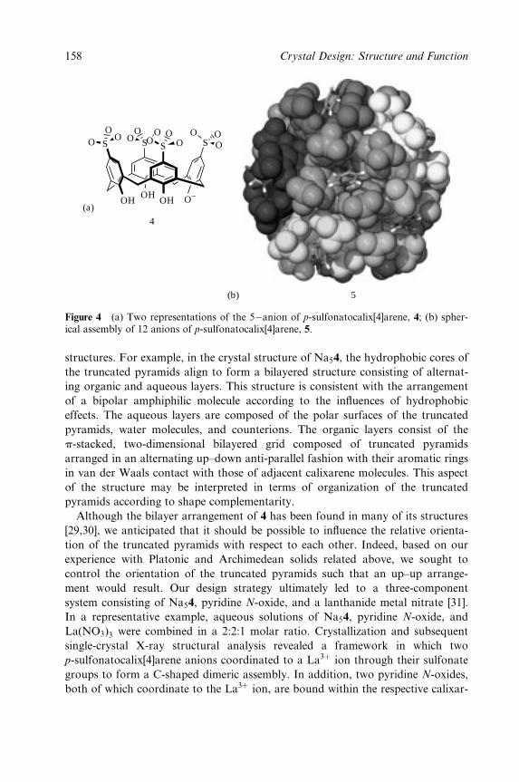
O OO
O−
SOOOOO
OOO
O S S S
OHOH
OH(a)
(b) 5
4
Figure 4 (a) Two representations of the 5ÿanion of p-sulfonatocalix[4]arene, 4; (b) spher-ical assembly of 12 anions of p-sulfonatocalix[4]arene, 5.
structures. For example, in the crystal structure of Na54, the hydrophobic cores of
the truncated pyramids align to form a bilayered structure consisting of alternat-
ing organic and aqueous layers. This structure is consistent with the arrangement
of a bipolar amphiphilic molecule according to the in¯uences of hydrophobic
effects. The aqueous layers are composed of the polar surfaces of the truncated
pyramids, water molecules, and counterions. The organic layers consist of the
p-stacked, two-dimensional bilayered grid composed of truncated pyramids
arranged in an alternating up±down anti-parallel fashion with their aromatic rings
in van der Waals contact with those of adjacent calixarene molecules. This aspect
of the structure may be interpreted in terms of organization of the truncated
pyramids according to shape complementarity.
Although the bilayer arrangement of 4 has been found in many of its structures
[29,30], we anticipated that it should be possible to in¯uence the relative orienta-
tion of the truncated pyramids with respect to each other. Indeed, based on our
experience with Platonic and Archimedean solids related above, we sought to
control the orientation of the truncated pyramids such that an up±up arrange-
ment would result. Our design strategy ultimately led to a three-component
system consisting of Na54, pyridine N-oxide, and a lanthanide metal nitrate [31].
In a representative example, aqueous solutions of Na54, pyridine N-oxide, and
La(NO3)3 were combined in a 2:2:1 molar ratio. Crystallization and subsequent
single-crystal X-ray structural analysis revealed a framework in which two
p-sulfonatocalix[4]arene anions coordinated to a La3� ion through their sulfonate
groups to form a C-shaped dimeric assembly. In addition, two pyridine N-oxides,
both of which coordinate to the La3� ion, are bound within the respective calixar-
158 Crystal Design: Structure and Function
ene cavities of the dimer. In these dimeric assemblies, the La3� ion acts a hinge,
and the steric requirements of the pyridine N-oxides binding concomitantly to the
La3� ion and the calixarene cavities, impart a dihedral angle of ca. 608 between
the p-sulfonatocalix[4]arene anions. This structural feature helps 4 assemble into
structures with curved surfaces, such as spherical clusters, 5 [31].
The amount of `chemical space' enclosed by spherical assembly 5 is about
1700 ÊA3. This space houses 30 water molecules and two sodium ions. However,
the van der Waals volume of 5 is about 11 000 ÊA3. Structure 5 is differentiated
from 1 by several factors. First, the supramolecular forces used to hold 1 together
are hydrogen bonds, while a combination of van der Waals forces, p-stacking
forces, and metal ion coordinate covalent bonds is employed for 5. Second, the
surface which encloses the chemical space is essentially one atom thick for 1,
whereas it is the thickness of the p-sulfonatocalix[4]arene building block in 5
(hence the 11 000 ÊA3 volume of the assembly with only 1700 ÊA3 of space within).
Third, the contents of the capsule are ordered for 5 (by the hydrogen bonds from
the enclosed water to the phenolic oxygen atom hydrogen bond acceptors at the
base of the p-sulfonatocalix[4]arene), but the contents are completely disordered
for 1 (because of the lack of any directional bonding force connecting the skeleton
of the assembly to the contents therein).
In the context of the discussion of Platonic and Archimedean solids, it is inter-
esting that spherical assembly 5 corresponds to a great rhombicuboctahedron. As
can be seen from Table 2, the great rhombicuboctahedron consists of 12 square
faces, together with eight hexagons and six octagons. The square faces are the
upper rims of the calix[4]arenes (the larger square faces of the truncated pyra-
mids). Since there are 12 calix[4]arenes, there are 12 square faces, as called for by
the great rhombicuboctahedron. However, the hexagons and the octagons are not
represented by chemical compounds. Rather, the hexagons and octagons are
formed by connecting three calix[4]arenes (squares) or four calix[4]arenes, respect-
ively. That is to say, the lines connecting the squares for the great rhombicubocta-
hedron in Figure 3 do not represent chemical bonds, weak or strong. Indeed, the
hexagons and octagons in 5 are not regular, but are approximations, just as
the upper rim of the p-sulfonatocalix[4]arene is an approximation of a square.
One must accept the fact that complex building blocks of large supramolecular
assemblies may often only approximate the triangles, squares, pentagons, etc.
called for by the Platonic or Archimedean solids.
There is a second limitation to the use of Platonic and Archimedean solids as
models for supramolecular assemblies. For example, the snub dodecahedron is a
target of some of our synthetic efforts. For the snub dodecahedron, a total of 60 tri-
angles is called for, but triangles can be simply the result of hydrogen bonds from
adjacent triangles or pentagons. For example, the snub cube in Figure 1 is composed
of 32 triangles and six squares, with the triangles being represented by water mol-
ecules and the squares, resorcin[4]arenes, 2. However, in assembly 1 only eight of
the 32 triangles contain water molecules, as one can observe from the shading in
Very Large Supramolecular Capsules Based on Hydrogen Bonding 159
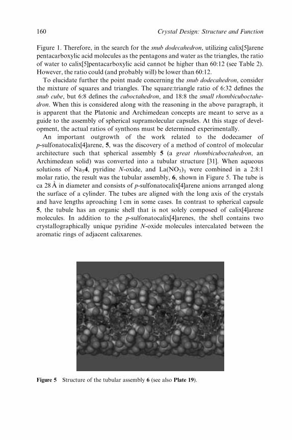
Figure 1. Therefore, in the search for the snub dodecahedron, utilizing calix[5]arene
pentacarboxylic acid molecules as the pentagons and water as the triangles, the ratio
of water to calix[5]pentacarboxylic acid cannot be higher than 60:12 (see Table 2).
However, the ratio could (and probably will) be lower than 60:12.
To elucidate further the point made concerning the snub dodecahedron, consider
the mixture of squares and triangles. The square:triangle ratio of 6:32 de®nes the
snub cube, but 6:8 de®nes the cuboctahedron, and 18:8 the small rhombicuboctahe-
dron. When this is considered along with the reasoning in the above paragraph, it
is apparent that the Platonic and Archimedean concepts are meant to serve as a
guide to the assembly of spherical supramolecular capsules. At this stage of devel-
opment, the actual ratios of synthons must be determined experimentally.
An important outgrowth of the work related to the dodecamer of
p-sulfonatocalix[4]arene, 5, was the discovery of a method of control of molecular
architecture such that spherical assembly 5 (a great rhombicuboctahedron, an
Archimedean solid) was converted into a tubular structure [31]. When aqueous
solutions of Na54, pyridine N-oxide, and La(NO3)3 were combined in a 2:8:1
molar ratio, the result was the tubular assembly, 6, shown in Figure 5. The tube is
ca 28 AÊ in diameter and consists of p-sulfonatocalix[4]arene anions arranged along
the surface of a cylinder. The tubes are aligned with the long axis of the crystals
and have lengths aproaching 1 cm in some cases. In contrast to spherical capsule
5, the tubule has an organic shell that is not solely composed of calix[4]arene
molecules. In addition to the p-sulfonatocalix[4]arenes, the shell contains two
crystallographically unique pyridine N-oxide molecules intercalated between the
aromatic rings of adjacent calixarenes.
Figure 5 Structure of the tubular assembly 6 (see also Plate 19).
160 Crystal Design: Structure and Function
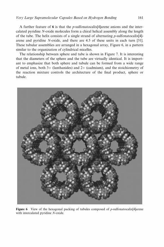
A further feature of 6 is that the p-sulfonatocalix[4]arene anions and the inter-
calated pyridine N-oxide molecules form a chiral helical assembly along the length
of the tube. The helix consists of a single strand of alternating p-sulfonatocalix[4]-
arene and pyridine N-oxide, and there are 4.5 of these units in each turn [31].
These tubular assemblies are arranged in a hexagonal array, Figure 6, in a pattern
similar to the organization of cylindrical micelles.
The relationship between sphere and tube is shown in Figure 7. It is interesting
that the diameters of the sphere and the tube are virtually identical. It is import-
ant to emphasize that both sphere and tubule can be formed from a wide range
of metal ions, both 3� (lanthanides) and 2� (cadmium), and the stoichiometry of
the reaction mixture controls the architecture of the ®nal product, sphere or
tubule.
Figure 6 View of the hexagonal packing of tubules composed of p-sulfonatocalix[4]arenewith intercalated pyridine N-oxide.
Very Large Supramolecular Capsules Based on Hydrogen Bonding 161
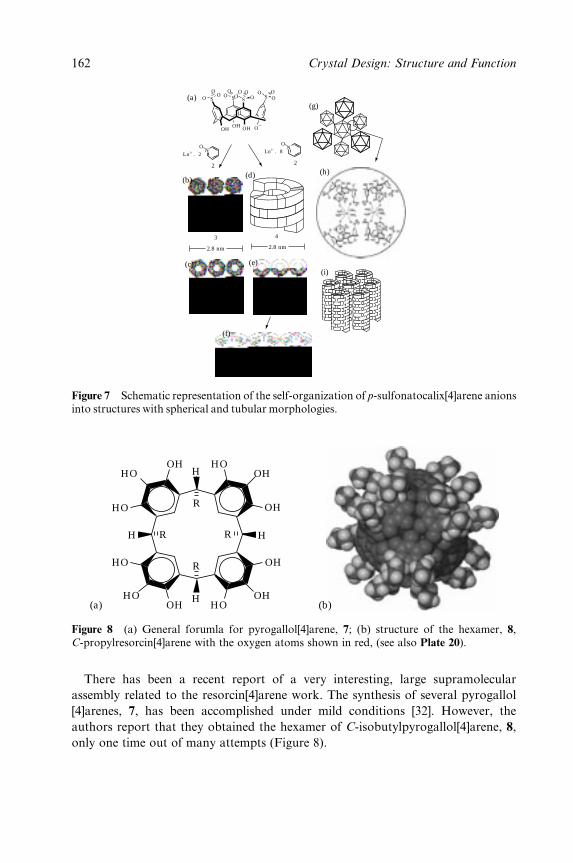
NO N
O
Ln3+ . 2 Ln3+ . 8
O O OOO O
OOOO O
OS S S S
OHOH OH O−
2.8 nm 2.8 nm
3
2 2
4
(a)
(b)
(c) (e)
(f)
(i)
(h)
(g)
(d)
Figure 7 Schematic representation of the self-organization of p-sulfonatocalix[4]arene anionsinto structures with spherical and tubular morphologies.
H
H
H
H
R
R
R
R
OHHO
HO
HOOH
OH
OH
OHHOOH
HO
HO
(a) (b)
Figure 8 (a) General forumla for pyrogallol[4]arene, 7; (b) structure of the hexamer, 8,C-propylresorcin[4]arene with the oxygen atoms shown in red, (see also Plate 20).
There has been a recent report of a very interesting, large supramolecular
assembly related to the resorcin[4]arene work. The synthesis of several pyrogallol
[4]arenes, 7, has been accomplished under mild conditions [32]. However, the
authors report that they obtained the hexamer of C-isobutylpyrogallol[4]arene, 8,
only one time out of many attempts (Figure 8).
162 Crystal Design: Structure and Function
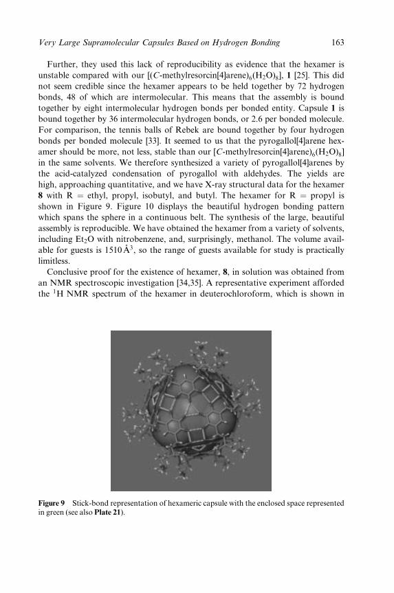
Further, they used this lack of reproducibility as evidence that the hexamer is
unstable compared with our [(C-methylresorcin[4]arene)6(H2O)8], 1 [25]. This did
not seem credible since the hexamer appears to be held together by 72 hydrogen
bonds, 48 of which are intermolecular. This means that the assembly is bound
together by eight intermolecular hydrogen bonds per bonded entity. Capsule 1 is
bound together by 36 intermolecular hydrogen bonds, or 2.6 per bonded molecule.
For comparison, the tennis balls of Rebek are bound together by four hydrogen
bonds per bonded molecule [33]. It seemed to us that the pyrogallol[4]arene hex-
amer should be more, not less, stable than our [C-methylresorcin[4]arene)6(H2O)8]
in the same solvents. We therefore synthesized a variety of pyrogallol[4]arenes by
the acid-catalyzed condensation of pyrogallol with aldehydes. The yields are
high, approaching quantitative, and we have X-ray structural data for the hexamer
8 with R � ethyl, propyl, isobutyl, and butyl. The hexamer for R � propyl is
shown in Figure 9. Figure 10 displays the beautiful hydrogen bonding pattern
which spans the sphere in a continuous belt. The synthesis of the large, beautiful
assembly is reproducible. We have obtained the hexamer from a variety of solvents,
including Et2O with nitrobenzene, and, surprisingly, methanol. The volume avail-
able for guests is 1510 ÊA3, so the range of guests available for study is practically
limitless.
Conclusive proof for the existence of hexamer, 8, in solution was obtained from
an NMR spectroscopic investigation [34,35]. A representative experiment afforded
the 1H NMR spectrum of the hexamer in deuterochloroform, which is shown in
Figure 9 Stick-bond representation of hexameric capsule with the enclosed space representedin green (see also Plate 21).
Very Large Supramolecular Capsules Based on Hydrogen Bonding 163
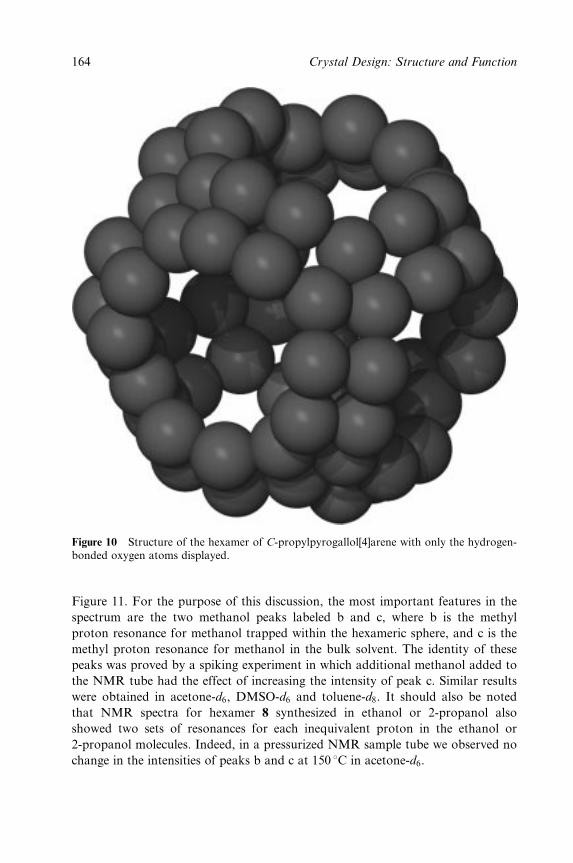
Figure 10 Structure of the hexamer of C-propylpyrogallol[4]arene with only the hydrogen-bonded oxygen atoms displayed.
Figure 11. For the purpose of this discussion, the most important features in the
spectrum are the two methanol peaks labeled b and c, where b is the methyl
proton resonance for methanol trapped within the hexameric sphere, and c is the
methyl proton resonance for methanol in the bulk solvent. The identity of these
peaks was proved by a spiking experiment in which additional methanol added to
the NMR tube had the effect of increasing the intensity of peak c. Similar results
were obtained in acetone-d6, DMSO-d6 and toluene-d8. It should also be noted
that NMR spectra for hexamer 8 synthesized in ethanol or 2-propanol also
showed two sets of resonances for each inequivalent proton in the ethanol or
2-propanol molecules. Indeed, in a pressurized NMR sample tube we observed no
change in the intensities of peaks b and c at 150 8C in acetone-d6.
164 Crystal Design: Structure and Function
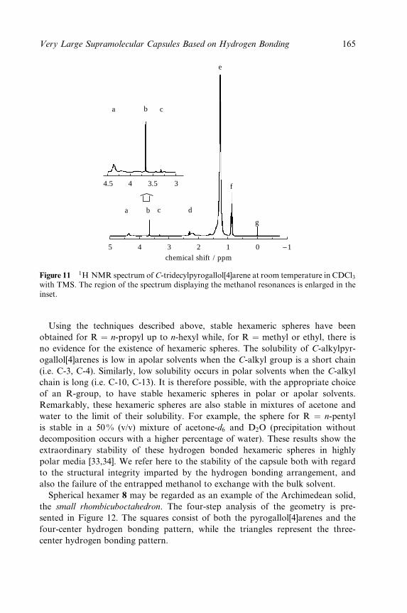
chemical shift / ppm
5 4
4.5 4 3.5 3
3 2 1 0 −1
f
g
d
e
c
c
b
b
a
a
Figure 11 1H NMR spectrum of C-tridecylpyrogallol[4]arene at room temperature in CDCl3with TMS. The region of the spectrum displaying the methanol resonances is enlarged in theinset.
Using the techniques described above, stable hexameric spheres have been
obtained for R � n-propyl up to n-hexyl while, for R � methyl or ethyl, there is
no evidence for the existence of hexameric spheres. The solubility of C-alkylpyr-
ogallol[4]arenes is low in apolar solvents when the C-alkyl group is a short chain
(i.e. C-3, C-4). Similarly, low solubility occurs in polar solvents when the C-alkyl
chain is long (i.e. C-10, C-13). It is therefore possible, with the appropriate choice
of an R-group, to have stable hexameric spheres in polar or apolar solvents.
Remarkably, these hexameric spheres are also stable in mixtures of acetone and
water to the limit of their solubility. For example, the sphere for R � n-pentyl
is stable in a 50% (v/v) mixture of acetone-d6 and D2O (precipitation without
decomposition occurs with a higher percentage of water). These results show the
extraordinary stability of these hydrogen bonded hexameric spheres in highly
polar media [33,34]. We refer here to the stability of the capsule both with regard
to the structural integrity imparted by the hydrogen bonding arrangement, and
also the failure of the entrapped methanol to exchange with the bulk solvent.
Spherical hexamer 8 may be regarded as an example of the Archimedean solid,
the small rhombicuboctahedron. The four-step analysis of the geometry is pre-
sented in Figure 12. The squares consist of both the pyrogallol[4]arenes and the
four-center hydrogen bonding pattern, while the triangles represent the three-
center hydrogen bonding pattern.
Very Large Supramolecular Capsules Based on Hydrogen Bonding 165
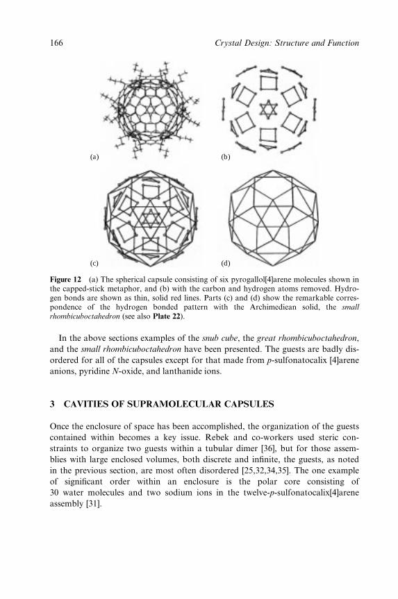
(a) (b)
(c) (d)
Figure 12 (a) The spherical capsule consisting of six pyrogallol[4]arene molecules shown inthe capped-stick metaphor, and (b) with the carbon and hydrogen atoms removed. Hydro-gen bonds are shown as thin, solid red lines. Parts (c) and (d) show the remarkable corres-pondence of the hydrogen bonded pattern with the Archimediean solid, the small
rhombicuboctahedron (see also Plate 22).
In the above sections examples of the snub cube, the great rhombicuboctahedron,
and the small rhombicuboctahedron have been presented. The guests are badly dis-
ordered for all of the capsules except for that made from p-sulfonatocalix [4]arene
anions, pyridine N-oxide, and lanthanide ions.
3 CAVITIES OF SUPRAMOLECULAR CAPSULES
Once the enclosure of space has been accomplished, the organization of the guests
contained within becomes a key issue. Rebek and co-workers used steric con-
straints to organize two guests within a tubular dimer [36], but for those assem-
blies with large enclosed volumes, both discrete and in®nite, the guests, as noted
in the previous section, are most often disordered [25,32,34,35]. The one example
of signi®cant order within an enclosure is the polar core consisting of
30 water molecules and two sodium ions in the twelve-p-sulfonatocalix[4]arene
assembly [31].
166 Crystal Design: Structure and Function
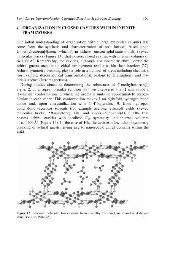
4 ORGANIZATION IN CLOSED CAVITIES WITHIN INFINITE
FRAMEWORKS
Our initial understanding of organization within large molecular capsules has
come from the synthesis and characterization of host lattices, based upon
C-methylresorcin[4]arene, which form hitherto unseen solid-state motifs, skewed
molecular bricks (Figure 13), that possess closed cavities with internal volumes of
ca 1000 ÊA3. Remarkably, the cavities, although not inherently chiral, order the
achiral guests such that a chiral arrangement results within their interiors [37].
Achiral symmetry breaking plays a role in a number of areas including chemistry
(for example, stereochemical transformations), biology (differentiation), and ma-
terials science (ferromagnetism).
During studies aimed at determining the robustness of C-methylresorcin[4]
arene, 2, as a supramolecular synthon [38], we discovered that 2 can adopt a
`T-shaped' conformation in which the aromatic units lie approximately perpen-
dicular to each other. This conformation makes 2 an eightfold hydrogen bond
donor and, upon cocrystallization with 4, 40-bipyridine, 9, from hydrogen
bond donor±acceptor solvents (for example acetone, ethanol) yields skewed
molecular bricks, 2.9�4(acetone), 10a, and 2�2(9)�3.5(ethanol)�H2O, 10b, that
possess achiral cavities with idealized C2h symmetry and internal volumes
of ca 1000 ÊA3 (Figure 14). In the case of 10b, the cavities allow achiral symmetry
breaking of achiral guests, giving rise to nanoscopic chiral domains within the
solid.
Figure 13 Skewed molecular bricks made from C-methylresorcin[4]arene and 4, 40-bipyr-idine (see also Plate 23).
Very Large Supramolecular Capsules Based on Hydrogen Bonding 167
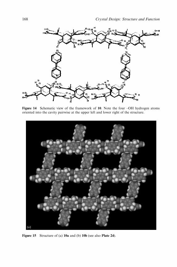
Figure 14 Schematic view of the framework of 10. Note the four ±OH hydrogen atomsoriented into the cavity pairwise at the upper left and lower right of the structure.
(a)
Figure 15 Structure of (a) 10a and (b) 10b (see also Plate 24).
168 Crystal Design: Structure and Function
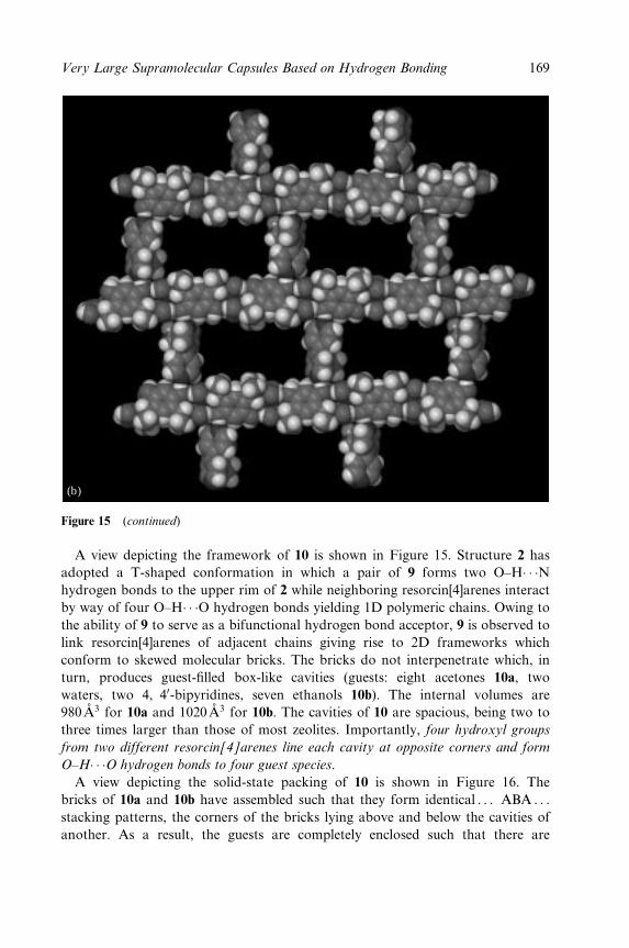
(b)
Figure 15 (continued)
A view depicting the framework of 10 is shown in Figure 15. Structure 2 has
adopted a T-shaped conformation in which a pair of 9 forms two O±H� � �Nhydrogen bonds to the upper rim of 2 while neighboring resorcin[4]arenes interact
by way of four O±H� � �O hydrogen bonds yielding 1D polymeric chains. Owing to
the ability of 9 to serve as a bifunctional hydrogen bond acceptor, 9 is observed to
link resorcin[4]arenes of adjacent chains giving rise to 2D frameworks which
conform to skewed molecular bricks. The bricks do not interpenetrate which, in
turn, produces guest-®lled box-like cavities (guests: eight acetones 10a, two
waters, two 4, 40-bipyridines, seven ethanols 10b). The internal volumes are
980 ÊA3 for 10a and 1020 ÊA3 for 10b. The cavities of 10 are spacious, being two to
three times larger than those of most zeolites. Importantly, four hydroxyl groups
from two different resorcin[4]arenes line each cavity at opposite corners and form
O±H� � �O hydrogen bonds to four guest species.
A view depicting the solid-state packing of 10 is shown in Figure 16. The
bricks of 10a and 10b have assembled such that they form identical . . . ABA . . .
stacking patterns, the corners of the bricks lying above and below the cavities of
another. As a result, the guests are completely enclosed such that there are
Very Large Supramolecular Capsules Based on Hydrogen Bonding 169
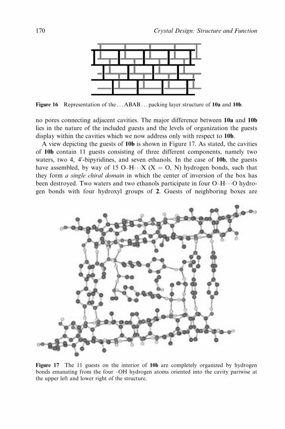
Figure 16 Representation of the . . . ABAB . . . packing layer structure of 10a and 10b.
no pores connecting adjacent cavities. The major difference between 10a and 10b
lies in the nature of the included guests and the levels of organization the guests
display within the cavities which we now address only with respect to 10b.
A view depicting the guests of 10b is shown in Figure 17. As stated, the cavities
of 10b contain 11 guests consisting of three different components, namely two
waters, two 4, 40-bipyridines, and seven ethanols. In the case of 10b, the guests
have assembled, by way of 15 O±H� � �X (X � O, N) hydrogen bonds, such that
they form a single chiral domain in which the center of inversion of the box has
been destroyed. Two waters and two ethanols participate in four O±H� � �O hydro-
gen bonds with four hydroxyl groups of 2. Guests of neighboring boxes are
Figure 17 The 11 guests on the interior of 10b are completely organized by hydrogenbonds emanating from the four ±OH hydrogen atoms oriented into the cavity pariwise atthe upper left and lower right of the structure.
170 Crystal Design: Structure and Function
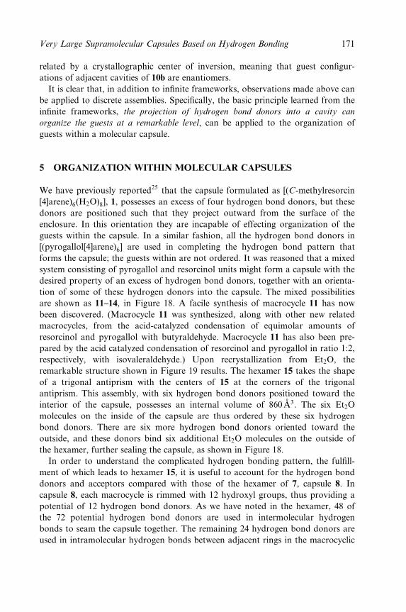
related by a crystallographic center of inversion, meaning that guest con®gur-
ations of adjacent cavities of 10b are enantiomers.
It is clear that, in addition to in®nite frameworks, observations made above can
be applied to discrete assemblies. Speci®cally, the basic principle learned from the
in®nite frameworks, the projection of hydrogen bond donors into a cavity can
organize the guests at a remarkable level, can be applied to the organization of
guests within a molecular capsule.
5 ORGANIZATION WITHIN MOLECULAR CAPSULES
We have previously reported25 that the capsule formulated as [(C-methylresorcin
[4]arene)6(H2O)8], 1, possesses an excess of four hydrogen bond donors, but these
donors are positioned such that they project outward from the surface of the
enclosure. In this orientation they are incapable of effecting organization of the
guests within the capsule. In a similar fashion, all the hydrogen bond donors in
[(pyrogallol[4]arene)6] are used in completing the hydrogen bond pattern that
forms the capsule; the guests within are not ordered. It was reasoned that a mixed
system consisting of pyrogallol and resorcinol units might form a capsule with the
desired property of an excess of hydrogen bond donors, together with an orienta-
tion of some of these hydrogen donors into the capsule. The mixed possibilities
are shown as 11±14, in Figure 18. A facile synthesis of macrocycle 11 has now
been discovered. (Macrocycle 11 was synthesized, along with other new related
macrocycles, from the acid-catalyzed condensation of equimolar amounts of
resorcinol and pyrogallol with butyraldehyde. Macrocycle 11 has also been pre-
pared by the acid catalyzed condensation of resorcinol and pyrogallol in ratio 1:2,
respectively, with isovaleraldehyde.) Upon recrystallization from Et2O, the
remarkable structure shown in Figure 19 results. The hexamer 15 takes the shape
of a trigonal antiprism with the centers of 15 at the corners of the trigonal
antiprism. This assembly, with six hydrogen bond donors positioned toward the
interior of the capsule, possesses an internal volume of 860 ÊA3. The six Et2O
molecules on the inside of the capsule are thus ordered by these six hydrogen
bond donors. There are six more hydrogen bond donors oriented toward the
outside, and these donors bind six additional Et2O molecules on the outside of
the hexamer, further sealing the capsule, as shown in Figure 18.
In order to understand the complicated hydrogen bonding pattern, the ful®ll-
ment of which leads to hexamer 15, it is useful to account for the hydrogen bond
donors and acceptors compared with those of the hexamer of 7, capsule 8. In
capsule 8, each macrocycle is rimmed with 12 hydroxyl groups, thus providing a
potential of 12 hydrogen bond donors. As we have noted in the hexamer, 48 of
the 72 potential hydrogen bond donors are used in intermolecular hydrogen
bonds to seam the capsule together. The remaining 24 hydrogen bond donors are
used in intramolecular hydrogen bonds between adjacent rings in the macrocyclic
Very Large Supramolecular Capsules Based on Hydrogen Bonding 171

11 12
13 14
H
H
H
H
R
R
R
R
OHH
HO
HOOH
OH
OH
OHHOOH
HO
HO
H
H
H
H
R
R
R
R
HOOH
OH
OH
HOH
OHHO
HO
HO
HOH
H
H
H
H
R
R
R
R
HOH
HO
HO
HOOH HO
OH
OH
OH
HHO
H
H
H
H
R
R
R
R
HOH
HO
HO
HOH HO
OH
OH
OH
HHO
Figure 18 Macrocycles composed of resorcinol and pyrogallol units.
building block 7. In the capsule of mixed macrocycle 11, each mixed marcocycle is
rimmed with 11 hydroxyl groups, providing a potential of 66 hydrogen bond
donors in the hexamer. A detailed study of Figure 19 shows that 24 hydrogen
bond donors are used in intermolecular hydrogen bonds and 24 are used in intra-
molecular hydrogen bonds (as in capsule 8). Of the 66ÿ 48 � 18 remaining
hydrogen bond donors, six are oriented toward the inside and six toward the
outside, bonding the diethyl ether molecules. The internal diethyl ether molecules
are bound by a hydrogen bond to one of the resorcinol ring OH groups, while the
external diethyl ether molecules are bound by a hydrogen bond to one of the
1-OH groups of a pyrogallol ring.
The accounting of the hydrogen bond donors discussed above may be com-
pleted by noting that the hexamer in Figure 19 has 24 intermolecular hydrogen
bonds, 24 intramolecular hydrogen bonds, and 12 hydrogen bonds to diethyl
ether molecules, for a total of 60 hydrogen bonds. The remaining six hydrogen
bond donors which are not involved in the O±H� � �O hydrogen bonding scheme
are found external to the capsule, as may be seen in Figure 19.
172 Crystal Design: Structure and Function
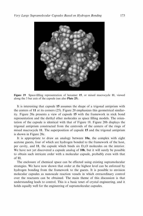
Figure 19 Space-®lling representation of hexamer 15, or mixed macrocycle 11, viewedalong the 3 bar axis of the capsule (see also Plate 25).
It is interesting that capsule 15 assumes the shape of a trigonal antiprism with
the centers of 11 at its corners (25). Figure 20 emphasizes this geometrical similar-
ity. Figure 20a presents a view of capsule 15 with the framework in stick bond
representation and the diethyl ether molecules as space ®lling models. The orien-
tation of the capsule is identical with that of Figure 18. Figure 20b displays the
trigonal antiprism constructed from the centroids of the centers of the rings of
mixed macrocycle 11. The superposition of capsule 15 and the trigonal antiprism
is shown in Figure 20c.
It is appropriate to draw an analogy between 10a, the complex with eight
acetone guests, four of which are hydrogen bonded to the framework of the host,
per cavity, and 11, the capsule which binds six Et2O molecules on the interior.
We have not yet discovered a capsule analog of 10b, but it will surely be possible
to obtain such intricate order with a molecular capsule, probably even with that
of 11.
The enclosure of chemical space can be effected using existing supramolecular
strategies. We have now shown that order at the highest level can be enforced by
hydrogen bonding from the framework to the guests. It is possible to envision
molecular capsules as nanoscale reaction vessels in which extraordinary control
over the reactants can be obtained. The main theme of this discussion is that
understanding leads to control. This is a basic tenet of crystal engineering, and it
holds equally well for the engineering of supramolecular capsules.
Very Large Supramolecular Capsules Based on Hydrogen Bonding 173
Figure 20 (a) Capsule 15 shown in stick bond representation with the diethyl ether guestsgiven in space ®lling representation. The orientation of the capsule is identical with thatgiven in Figure 18. (b) The trigonal antiprism that results from connection of the centroidsof the centers of the aromatic rings of macrocycle 11. (c) Superposition of the trigonalantiprism and capsule (see also Plate 26).
REFERENCES
1. Avers, C. J. Molecular Cell Biology. Addison-Wesley, Reading, MA, 1986, pp. 768±770.2. The term `chemical space' is used to specify that area within a molecular capsule which
may be used to house a guest.3. Caspar, D.; Klug, A. Cold Spring Harbor Symp. Quant. Biol. 1962, 27, 1±24.
174 Crystal Design: Structure and Function
4. Branden, C.; Tooze, J. Introduction to Protein Structure. Garland, New York, 1991,pp. 161±177.
5. Hogle, J. M., Chow, M.; Filman, D. J. Science 1985, 229, 1358±1365.6. Douglas, T.; Young, M. Nature 1998, 191, 152±155.7. Douglas, T. in Biomimetic Approaches to Materials Science, ed. Mann, S. VCH, New
York, 1996, pp. 91±115.8. Cram, D. J.; Karbach, S.; Kim, Y. H.; Baczynskyj, L.; Kalleymeyn, G. W. J. Am.
Chem. Soc. 1985, 107, 2575.9. Gabard, J.; Collet, A. Chem. Commun. 1981, 1137±1138.
10. Chapman, R. G.; Sherman, J. C. J. Am. Chem. Soc. 1995, 117, 9081±9082.11. Chopra, N.; Sherman, J. C. Angew. Chem., Int. Ed. Engl. 1999, 38, 1955±1957.12. Wyler, R.; de Mendoza, J.; Rebek, J., Jr. Angew. Chem., Int. Ed. Engl. 1993, 32,
1699±1701.13. Conn, M. M.; Rebek, J., Jr. Chem. Rev. 1997, 97, 1647±1668.14. Rebek, J., Jr. Chem. Commun. 2000, 637±643.15. Shivanyuk, A.; Rebek, J., Jr. Chem. Commun. 2001, 2374±2375.16. Fujita, M.; Kwon, Y. J.; Washirzu, S.; Ogura, K. J. Am. Chem. Soc. 1994, 116,
1151±1152.17. Takeda, N.; Umemoto, K.; Yamaguchi, K.; Fujita, M. Nature 1999, 398, 794±796.18. Olenyuk, B.; Whiteford, J. A.; Fechtenkotter, A.; Stang, P. J. Nature 1999, 398,
796±799.19. Fox, O. D.; Dalley, N. K.; Harrison, R. G. J. Am. Chem. Soc. 1998, 120, 7111±7112.20. Hardie, M. J.; Raston, C. L. J. Chem. Soc., Dalton Trans. 2000, 2483±2492.21. Atwood, J. L., Barbour, L. J., Hardie, M. J.; Raston, C. L. Coord. Chem. Rev. 2001,
222, 3±32.22. Biradha, K., Seward, C.; Zaworotko, M. J. Angew. Chem., Int. Ed. Engl. 1999, 38,
492±495.23. Rose, K. N.; Barbour, L. J.; Orr, G. W.; Atwood, J. L. Chem. Commun. 1998, 407±408.24. Gibb, C. L. D.; Gibb, B. C. J. Supramol. Chem. 2001, 1, 39±52.25. MacGillivray, L. R.; Atwood, J. L. Nature 1997, 389, 469±472.26. Wenninger, M. J. Polyhedron Models. Cambridge University Press, New York, 1971.27. MacGillivray, L. R.; Atwood, J. L. Angew. Chem., Int. Ed. Engl. 1999, 38, 1019±1033.28. MacGillivray, L. R.; Atwood, J. L. in Advances in Supramolecular Chemistry, ed.
Gokel, G. W. JAI, Stamford, 2000, pp. 157±183.29. Atwood, J. L.; Hamada, F.; Robinson, K. D.; Orr, G. W.; Vincent, R. L. Nature 1991,
349, 683±685.30. Atwood, J. L.; Barbour, L. J.; Hardie, M. J.; Raston, C. L. Coord. Chem. Rev. 2001,
222, 3±32.31. Orr, G. W., Barbour, L. J.; Atwood, J. L. Science 1999, 285, 1049±1052.32. Gerkensmeier, T., Iwanek, W., Agena, C., Frohlich, R., Kotila, S., Nather, C.; Mattay,
J. Eur. J. Org. Chem. 1999, 2257±2262.33. Meissner, R. S.; Rebek, J.; de Mendoza, J. Science 1995, 270, 1485.34. Atwood, J. L., Barbour, L. J.; Jerga, A. Chem. Commun. 2001, 2376±2377.35. Atwood, J. L., Barbour, L. J.; Jerga, A. J. Supramol. Chem., 2001, 1, 131±134.36. Heinz, T., Rudkevich, D. M.; Rebek, J., Jr. Nature 1998, 394, 764±766.37. MacGillivray, L. R.; Holman, K. T.; Atwood, J. L. J. Supramol. Chem., 2001, 1, 125±130.38. Desiraju, G. R. Angew. Chem., Int. Ed. Engl. 1995, 34, 2311.
AQ1
AQ2
Very Large Supramolecular Capsules Based on Hydrogen Bonding 175
Chapter 4
Molecular Tectonics: MolecularNetworks Based on InclusionProcesses
JULIEN MARTZ, ERNEST GRAF, ANDREÂ DE CIAN AND
MIR WAIS HOSSEINI
Universite Louis Pasteur, Institut Le Bel, Strasbourg, France
1 INTRODUCTION
Molecular solids are composed of molecular entities and are de®ned by the chem-
ical nature of their molecular components and by their interactions with respect to
each other in the solid phase. Molecular crystals are molecular solids presenting
order and periodicity. With our present level of knowledge, the complete under-
standing, and therefore prediction, of all intermolecular interactions in the crystal-
line phase seems, unreachable. Thus, it appears that crystal structures are not
entirely predictable [1]. This fact is at the origin of active debates on whether the
concept of crystal engineering is justi®able. However, following the statement by
Jack Dunitz, `A crystal is, in a sense, the supramolecule par excellence' [2], using
concepts developed in the area of supramolecular chemistry [3], one may predict
some of the inter-motive interactions. In other terms, as stated above, although all
intermolecular forces may not be controlled currently with accuracy, nevertheless,
by programming some of the interactions between the molecular components, one
may design molecular networks in the crystalline phase. Thus, our aim is centred
on the design and formation of molecular networks in the crystalline phase rather
than crystal engineering.
Crystal Design: Structure and Function. Volume 7Edited by Gautam R. Desiraju
Copyright 2003 John Wiley & Sons, Ltd.ISBN: 0-470-84333-0
2 MOLECULAR NETWORKS
A molecular network in the solid state is de®ned as a supramolecular structure,
theoretically composed of in®nite number of molecules named tectons (from the
Greek TEKTON, builder) [4] capable of mutual recognition. A tecton is an
informed molecular component containing in its backbone recognition sites dis-
posed in a speci®c manner. The speci®c intermolecular interaction between com-
plementary tectons leads to a recognition pattern which may be called an
assembling core. One may draw the analogy between the assembling core de®ned
in the context of molecular networks and a supramolecular synthon elaborated in
the area of crystal engineering [5]. Within the network, the assembling core
becomes a structural node and by translation of the latter the network is formed
(Figure 1). The dimensionality of the network is de®ned by the number of transla-
tions operating on the structural nodes. Whereas a 1-D network (also called
a-network) is obtained upon a single translation of the node (Figure 1a), two-(2-
D or b-network) and three-(3-D or g-network) dimensional networks are
obtained upon two (Figure 1b) and three (Figure 1c) translations of identical or
different structural nodes in two and three independent directions of space
respectively [6±8]. In dealing with molecular networks, the critical point is con-
cerned with the de®nition in terms of energy of interaction of the structural nodes.
Indeed, a crystal is by de®nition a 3-D structure. De®ning a network within a
crystalline arrangement requires an energy hierarchy between speci®c recognition
processes leading to the formation of the assembling core and other interactions
(van der Waals, electrostatic, etc.) responsible for the cohesion of the solid.
It is interesting that whereas molecules are described as assemblies of atoms
interconnected by covalent bonds, by analogy, one may describe molecular net-
works as hypermolecules in which the connectivity between tectons is ensured by
noncovalent inter-tecton interactions.
The construction of large molecular networks (10ÿ6±10ÿ3 m scale) in the crys-
talline phase with predicted and programmed structure may hardly be envisaged
through step by step type strategy. Indeed, taking into account the dimension of
tectons, usually in the order of 1 nm, a millimetric crystal would require the
controlled interconnection of ca 106 tectons. If the connectivity between tectons
was achieved step by step using the formation of covalent bonds, the formation of
the network would necessitate 1 million operations! However, the preparation of
such higher order solid materials may be reached through iterative self-assembling
processes [9±12] between tectons containing within their structure recognition sites
and a speci®c assembling algorithm which will operate as soon as complementary
tectons are allowed to interact. This strategy, called molecular tectonics [13],
seems to be the most viable one and is of ef®cient and frequent use in nature. The
molecular tectonics approach relies on a double analysis. One is at the molecular
level, dealing with the individual tectons composing the solid, and the other is
at the supramolecular level, dealing with the inter-tecton interactions [3,5].
178 Crystal Design: Structure and Function
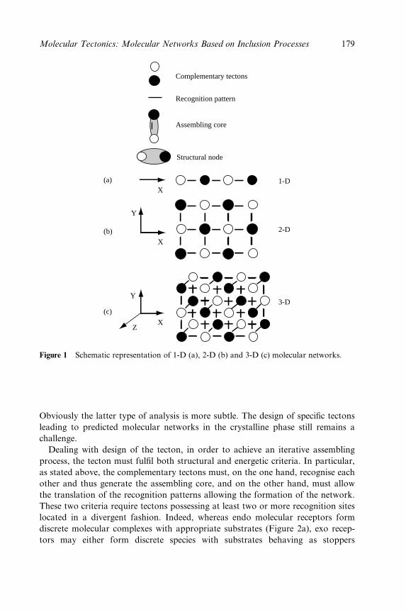
Complementary tectons
Recognition pattern
Assembling core
Structural node
(c)
(b)
(a)X
X
Y
XZ
Y
1-D
2-D
3-D
Figure 1 Schematic representation of 1-D (a), 2-D (b) and 3-D (c) molecular networks.
Obviously the latter type of analysis is more subtle. The design of speci®c tectons
leading to predicted molecular networks in the crystalline phase still remains a
challenge.
Dealing with design of the tecton, in order to achieve an iterative assembling
process, the tecton must ful®l both structural and energetic criteria. In particular,
as stated above, the complementary tectons must, on the one hand, recognise each
other and thus generate the assembling core, and on the other hand, must allow
the translation of the recognition patterns allowing the formation of the network.
These two criteria require tectons possessing at least two or more recognition sites
located in a divergent fashion. Indeed, whereas endo molecular receptors form
discrete molecular complexes with appropriate substrates (Figure 2a), exo recep-
tors may either form discrete species with substrates behaving as stoppers
Molecular Tectonics: Molecular Networks Based on Inclusion Processes 179
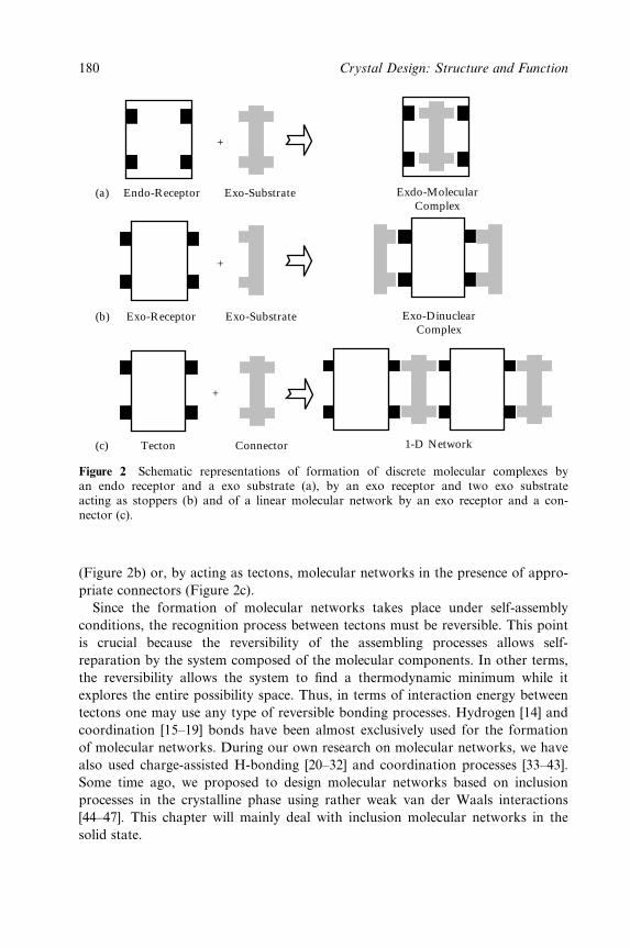
Endo-Receptor Exo-Substrate Exdo-MolecularComplex
Exo-DinuclearComplex
(a)
Exo-Receptor Exo-Substrate(b)
Tecton Connector 1-D Network(c)
+
+
+
Figure 2 Schematic representations of formation of discrete molecular complexes byan endo receptor and a exo substrate (a), by an exo receptor and two exo substrateacting as stoppers (b) and of a linear molecular network by an exo receptor and a con-nector (c).
(Figure 2b) or, by acting as tectons, molecular networks in the presence of appro-
priate connectors (Figure 2c).
Since the formation of molecular networks takes place under self-assembly
conditions, the recognition process between tectons must be reversible. This point
is crucial because the reversibility of the assembling processes allows self-
reparation by the system composed of the molecular components. In other terms,
the reversibility allows the system to ®nd a thermodynamic minimum while it
explores the entire possibility space. Thus, in terms of interaction energy between
tectons one may use any type of reversible bonding processes. Hydrogen [14] and
coordination [15±19] bonds have been almost exclusively used for the formation
of molecular networks. During our own research on molecular networks, we have
also used charge-assisted H-bonding [20±32] and coordination processes [33±43].
Some time ago, we proposed to design molecular networks based on inclusion
processes in the crystalline phase using rather weak van der Waals interactions
[44±47]. This chapter will mainly deal with inclusion molecular networks in the
solid state.
180 Crystal Design: Structure and Function

3 INCLUSION MOLECULAR NETWORKS
3.1 Design of Koilates
The chemistry of inclusion complexes based on host and guest molecules
(Figure 3a), i.e. the inclusion of a substrate within the cavity of a receptor mol-
ecule, is an established area [48±50]. Indeed, many endo receptors, possessing an
endomolecular cavity, have been designed to bind substrates in a inclusion fash-
ion. In some cases, the inclusion phenomena has been established in the crystal-
line phase by X-ray diffraction methods revealing their discrete nature. Because
the connection between the discrete complexes is not ensured by speci®c inter-
action in the solid, these molecular crystals can not be classi®ed as molecular
networks which require the repetition of recognition patterns. On the other hand,
the formation of clathrates [51,52] in the solid state has been truly investigated
during the past century by solid-state chemists (Figure 3b). Clathtrates are formed
when molecular components with speci®c shapes are arranged in the crystalline
phase in such a way that cavities are formed. The exo molecular cavities thus
obtained are occupied by guest molecules. We have extended the concept of inclu-
sion complexes in solution and in the solid state and the formation of clathrates
exclusively in the crystalline phase to the construction of a new type of molecular
networks in the solid state (Figure 3c). This strategy, based on inclusion phenom-
ena between concave and convex molecular objects, combines endo and exo mo-
lecular cavities. The basic concept guiding the design of inclusion networks, is
based on the use of koilands (from the Greek KOILOS, hollow) [44±47], multi-
cavity receptor molecules composed of at least two cavities arranged in a diver-
gent fashion (concave tectons), and connectors (convex tectons) capable of being
included within the cavities of the koilands and thus connecting consecutive koi-
lands by inclusion processes. Indeed, since each individual cavity offers the possi-
bility of forming inclusion complexes with a convex molecules, connecting two or
more of such cavities must lead in the presence of an appropriate connector to
non-covalently assembled polymeric species called koilates or inclusion networks.
The driving forces for the formation of koilates are, on the one hand, inter-
actions between cavities and connectors, and on the other hand, the best compac-
tion indispensable for the formation of the crystalline phase. The attractive forces
between the koiland and the connector may be of different nature such as electro-
static charge±charge, charge±dipole, dipole±dipole or van der Waals interactions.
Here, we shall mainly focus on the last case. As mentioned above, recognising a
network in a molecular crystal is a matter of translation of the recognition pat-
tern. As long as the energy of interaction de®ning the assembling core is larger as
in the case of strong H-bonds (charge assisted or not) or substantially greater as in the
case of coordination bonds than other interactions responsible for the for-
mation of the crystal (three-dimensional compaction of the individual net-
works), the network may be de®ned without ambiguity. However, for inclusion
Molecular Tectonics: Molecular Networks Based on Inclusion Processes 181

(a)
Host Guest
Inclusion Complex
Clathrate
KoilateConnectorKoiland
Clathrand Guest
(c)
(b)
Figure 3 Schematic representation of the formation of inclusion complexes based on therecognition of a guest molecule by a host receptor (a), of a clathrate based on the inclusionof guest molecules within cavities generated upon packing of clathrands in the solid state(b), and of a 1-D inclusion molecular network named koilate formed through interconnec-tion of hollow tectons (koilands) by connector molecules (c).
networks excessively based on van der Waals interaction or weak H-bonds
(1±10 kJ/mol of interaction), the task is not obvious since the packing of the
components may also be ensured by the same type of interactions. This dif®culty
may be overcome by considering the recognition pattern, formed by inclusion of a
section of the connector by the cavity of the koiland, as a supramolecular synthon
[5]. The term supramolecular synthon here means a recognition pattern which by
translation would become a structural node of the network.
In terms of design, one may envisage a variety of koilates with different dimen-
sionality. Considering a two-component system, 1-D koilates may be formed
using koilands possessing two divergent cavities. When using connectors with two
extremities each capable of being included within one of the two cavities and thus
connecting consecutive koilands, 1-D koilates may be formed (Figure 4a).
Another possibility may be based on a single self complementary tecton possess-
ing both a concave moiety acting as receptor and a convex part acting as the
connector. In that case, the 1-D inclusion network will be formed by self-inclusion
processes (Figure 4b and c). Dealing with 1-D koilates, as in the case of any type
of 1-D molecular networks, the design of directional koilates remains a challenge.
182 Crystal Design: Structure and Function
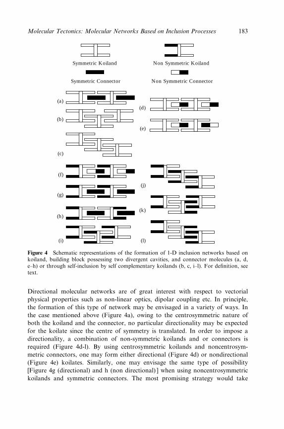
(a)(d)
(e)
(j)
(k)
(l)
(b)
(c)
(f)
(g)
(h)
(i)
Symmetric Koiland
Symmetric Connector
Non Symmetric Koiland
Non Symmetric Connector
Figure 4 Schematic representations of the formation of 1-D inclusion networks based onkoiland, building block possessing two divergent cavities, and connector molecules (a, d,e±h) or through self-inclusion by self complementary koilands (b, c, i±l). For de®nition, seetext.
Directional molecular networks are of great interest with respect to vectorial
physical properties such as non-linear optics, dipolar coupling etc. In principle,
the formation of this type of network may be envisaged in a variety of ways. In
the case mentioned above (Figure 4a), owing to the centrosymmetric nature of
both the koiland and the connector, no particular directionality may be expected
for the koilate since the centre of symmetry is translated. In order to impose a
directionality, a combination of non-symmetric koilands and or connectors is
required (Figure 4d-l). By using centrosymmetric koilands and noncentrosym-
metric connectors, one may form either directional (Figure 4d) or nondirectional
(Figure 4e) koilates. Similarly, one may envisage the same type of possibility
[Figure 4g (directional) and h (non directional) ] when using noncentrosymmetric
koilands and symmetric connectors. The most promising strategy would take
Molecular Tectonics: Molecular Networks Based on Inclusion Processes 183
advantage of recognition processes between the two cavities of the koiland and
the two extremities of the connector (Figure 4f). Indeed, noncentrosymmetric koi-
lands and connectors, if the recognition process is properly programmed, must
lead exclusively to the formation of directional koilates. As for symmetric koilates
mentioned above, again a single nonsymmetric self-complementary tecton may be
used. The koilate that can be formed by self-inclusion may either be directional
(Figure 4i and j) or nondirectional (Figure 4k and l). As will be presented in detail
and on real cases below, almost all possibilities mentioned above (Figure 4) have
been observed.
The 2- and 3-D koilates may be designed using koilands possessing three and
four cavities, respectively, oriented in a divergent fashion. Koilands based on
three interconnected cavities with an angle of 1208 between them were obtained.
In principle, this type of koiland may be assembled into a 2-D network using
linear connectors. Dealing with 3-D inclusion networks, one may envisage two
possibilities. Koilands possessing four cavities located on the apices of a tetrahe-
dron which in the presence of linear connectors would lead to 3-D koilates of the
diamondoid type, or koilands with six cavities occupying the apices of a octahe-
dron. In that case, in principle 3-D inclusion networks of the cubic type may be
envisaged, again using linear connectors. The formation of both 2- and 3-D inclu-
sion networks has not been yet achieved and remains an interesting challenge.
3.2 Design of Koilands
Calix[4]arene derivatives [53±56] are candidates of choice for the design of koi-
lands (Scheme 1). Indeed, these compounds offer a preorganised and tuneable
hydrophobic pocket surrounded by aryl moieties as well as four hydroxy groups
for further functionalisation. However, because of the junctions (CH2 or S)
between the aromatic moieties, calix[4]arenes present a conformational ¯exibility
(Figure 5). Calix[4]arenes bearing four free OH groups or O-alkylated derivatives
with short alkyl chains present four limit conformations [cone (c), partial cone
(pc), 1,2-alternate (1,2-a) and 1,3-alternate (1,3-a) ]. Among all conformers, only
the cone may be used for the design of koilands. Furthermore, these compounds,
easily prepared in large quantities, present another advantage in terms of design
related to the possibility of controlling both the entrance and the depth of the
preorganised cavity by the nature of the substituents R at the para position
(Scheme 1), i.e. H (1), Me (2), Et (3), iPr (4), C(CH3)3 (5), allyl (6) or Ph (7).
Furthermore, one may also replace the CH2 groups connecting the aromatic rings
by sulfur atoms (compound 8) [57±60], and ®nally, the substitution of the methyl-
ene groups by S atoms as well as the replacement of the OH groups by SH moiet-
ies may also be performed (compound 9)[61]. Whereas compounds 1 (Figure 6a),
3 (Figure 6b), 4 (Figure 6c), 5 (Figure 6d), 7 (Figure 6e) and 8 (Figure 6f) adopt
the cone conformation in the crystalline phase, compound 9 was shown to
184 Crystal Design: Structure and Function
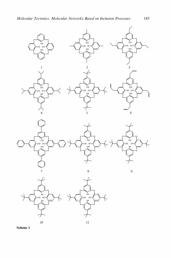
1
4
7
10 11
8 9
5 6
2 3
OH
OH
OH
HO
OH
OH
OH
HO
OH
OH
OH
HO OH
OH
OH
HO
OH
OH
OH
HO OH
OH
OH
HO OH
OH
OH
HO
OH
SH
SH
HO SH
SH
SH
HS
OH
OH
OH
HO
SS
SS
SH
SH
SH
HS
SS
SS
Scheme 1
Molecular Tectonics: Molecular Networks Based on Inclusion Processes 185
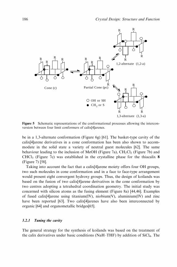
RR
RR R
RR
R
R
RR
R
R
R
R
R
1,2-alternate (1,2-a)
Partial Cone (pc)Cone (c)
1,3-alternate (1,3-a)
OH or SHCH2 or S
Figure 5 Schematic representations of the conformational processes allowing the intercon-version between four limit conformers of calix[4]arenes.
be in a 1,3-alternate conformation (Figure 6g) [61]. The basket-type cavity of the
calix[4]arene derivatives in a cone conformation has been also shown to accom-
modate in the solid state a variety of neutral guest molecules [62]. The same
behaviour leading to the inclusion of MeOH (Figure 7a), CH2Cl2 (Figure 7b) and
CHCl3 (Figure 7c) was established in the crystalline phase for the thiacalix 8
(Figure 7) [58].
Taking into account the fact that a calix[4]arene moiety offers four OH groups,
two such molecules in cone conformation and in a face to face-type arrangement
would present eight convergent hydroxy groups. Thus, the design of koilands was
based on the fusion of two calix[4]arene derivatives in the cone conformation by
two centres adopting a tetrahedral coordination geometry. The initial study was
concerned with silicon atoms as the fusing element (Figure 8a) [44,46]. Examples
of fused calix[4]arene using titanium(IV), niobium(V), aluminium(IV) and zinc
have been reported [63]. Two calix[4]arenes have also been interconnected by
organic [64] and organometallic bridges[65].
3.2.1 Tuning the cavity
The general strategy for the synthesis of koilands was based on the treatment of
the calix derivatives under basic conditions (NaH±THF) by addition of SiCl4. The
186 Crystal Design: Structure and Function
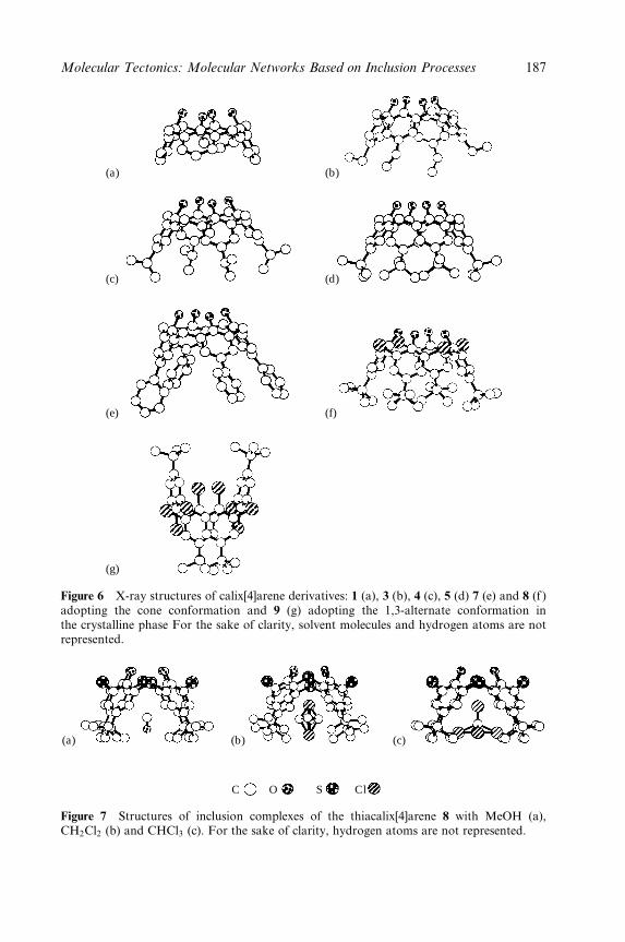
(g)
(a) (b)
(c) (d)
(e) (f)
Figure 6 X-ray structures of calix[4]arene derivatives: 1 (a), 3 (b), 4 (c), 5 (d) 7 (e) and 8 (f )adopting the cone conformation and 9 (g) adopting the 1,3-alternate conformation inthe crystalline phase For the sake of clarity, solvent molecules and hydrogen atoms are notrepresented.
(a) (b) (c)
C O S Cl
Figure 7 Structures of inclusion complexes of the thiacalix[4]arene 8 with MeOH (a),CH2Cl2 (b) and CHCl3 (c). For the sake of clarity, hydrogen atoms are not represented.
Molecular Tectonics: Molecular Networks Based on Inclusion Processes 187
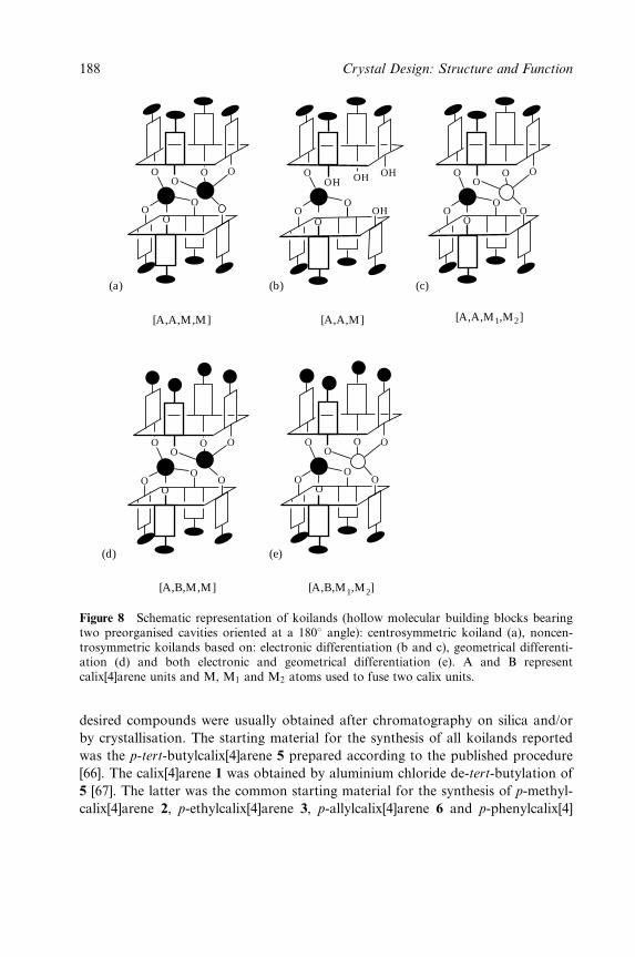
O
OO
OO
OO
O O
O
OOHOH O
OO
O OOOH
OOH
[A,A,M] [A,A,M1,M2]
(c)
OO
(b)
[A,A,M,M]
(a)
[A,B,M1,M2]
(e)
[A,B,M,M]
(d)
OO
O O
OO
O
OO
O O
OO
OO
Figure 8 Schematic representation of koilands (hollow molecular building blocks bearingtwo preorganised cavities oriented at a 1808 angle): centrosymmetric koiland (a), noncen-trosymmetric koilands based on: electronic differentiation (b and c), geometrical differenti-ation (d) and both electronic and geometrical differentiation (e). A and B representcalix[4]arene units and M, M1 and M2 atoms used to fuse two calix units.
desired compounds were usually obtained after chromatography on silica and/or
by crystallisation. The starting material for the synthesis of all koilands reported
was the p-tert-butylcalix[4]arene 5 prepared according to the published procedure
[66]. The calix[4]arene 1 was obtained by aluminium chloride de-tert-butylation of
5 [67]. The latter was the common starting material for the synthesis of p-methyl-
calix[4]arene 2, p-ethylcalix[4]arene 3, p-allylcalix[4]arene 6 and p-phenylcalix[4]
188 Crystal Design: Structure and Function
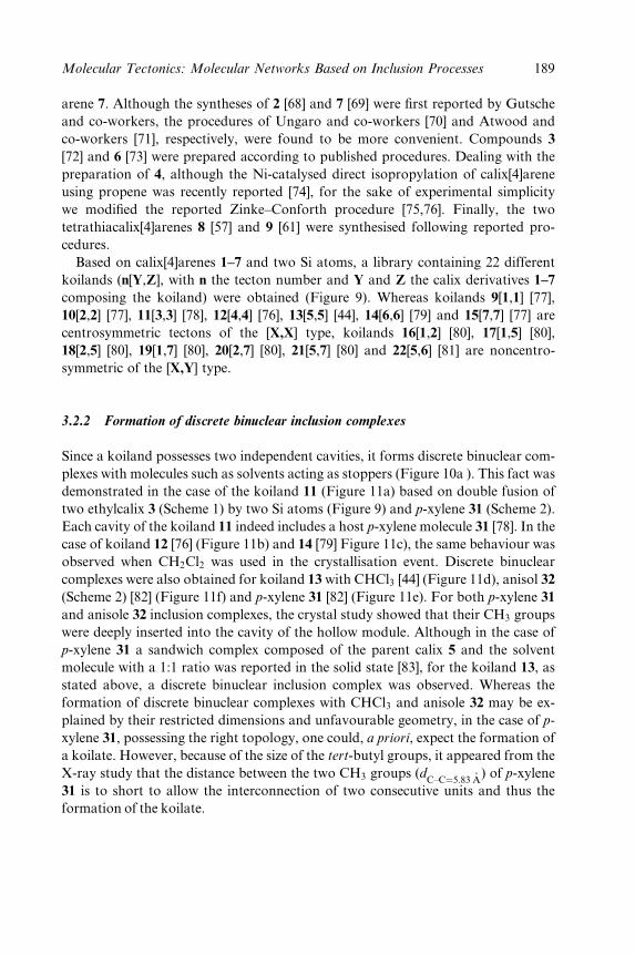
arene 7. Although the syntheses of 2 [68] and 7 [69] were ®rst reported by Gutsche
and co-workers, the procedures of Ungaro and co-workers [70] and Atwood and
co-workers [71], respectively, were found to be more convenient. Compounds 3
[72] and 6 [73] were prepared according to published procedures. Dealing with the
preparation of 4, although the Ni-catalysed direct isopropylation of calix[4]arene
using propene was recently reported [74], for the sake of experimental simplicity
we modi®ed the reported Zinke±Conforth procedure [75,76]. Finally, the two
tetrathiacalix[4]arenes 8 [57] and 9 [61] were synthesised following reported pro-
cedures.
Based on calix[4]arenes 1±7 and two Si atoms, a library containing 22 different
koilands (n[Y,Z], with n the tecton number and Y and Z the calix derivatives 1±7
composing the koiland) were obtained (Figure 9). Whereas koilands 9[1,1] [77],
10[2,2] [77], 11[3,3] [78], 12[4,4] [76], 13[5,5] [44], 14[6,6] [79] and 15[7,7] [77] are
centrosymmetric tectons of the [X,X] type, koilands 16[1,2] [80], 17[1,5] [80],
18[2,5] [80], 19[1,7] [80], 20[2,7] [80], 21[5,7] [80] and 22[5,6] [81] are noncentro-
symmetric of the [X,Y] type.
3.2.2 Formation of discrete binuclear inclusion complexes
Since a koiland possesses two independent cavities, it forms discrete binuclear com-
plexes with molecules such as solvents acting as stoppers (Figure 10a ). This fact was
demonstrated in the case of the koiland 11 (Figure 11a) based on double fusion of
two ethylcalix 3 (Scheme 1) by two Si atoms (Figure 9) and p-xylene 31 (Scheme 2).
Each cavity of the koiland 11 indeed includes a host p-xylene molecule 31 [78]. In the
case of koiland 12 [76] (Figure 11b) and 14 [79] Figure 11c), the same behaviour was
observed when CH2Cl2 was used in the crystallisation event. Discrete binuclear
complexes were also obtained for koiland 13 with CHCl3 [44] (Figure 11d), anisol 32
(Scheme 2) [82] (Figure 11f) and p-xylene 31 [82] (Figure 11e). For both p-xylene 31
and anisole 32 inclusion complexes, the crystal study showed that their CH3 groups
were deeply inserted into the cavity of the hollow module. Although in the case of
p-xylene 31 a sandwich complex composed of the parent calix 5 and the solvent
molecule with a 1:1 ratio was reported in the solid state [83], for the koiland 13, as
stated above, a discrete binuclear inclusion complex was observed. Whereas the
formation of discrete binuclear complexes with CHCl3 and anisole 32 may be ex-
plained by their restricted dimensions and unfavourable geometry, in the case of p-
xylene 31, possessing the right topology, one could, a priori, expect the formation of
a koilate. However, because of the size of the tert-butyl groups, it appeared from the
X-ray study that the distance between the two CH3 groups (dC±C�5:83 ÊA
) of p-xylene
31 is to short to allow the interconnection of two consecutive units and thus the
formation of the koilate.
Molecular Tectonics: Molecular Networks Based on Inclusion Processes 189

O
O
O
OO
O O
SiSi
O
O
O
O
OO
O O
SiSi
O
O
O
O
OO
O O
SiSi
O
O
O
O
OO
O O
SiSi
O
O
O
O
OO
O O
SiSi
O
O
O
O
OO
O O
SiSi
O
O
O
O
OO
O O
SiSi
O
O
O
O
OO
O O
SiSi
O
O
O
O
OO
O O
SiSi
O
O
O
O
OO
O O
SiSi
O
O
O
O
OO
O O
SiSi
O
O
O
O
OO
O O
SiSi
O
O
O
O
OO
O O
SiSi
O
O
O
OH
O OH
OH OH
Si
O
O
O
O
OO
O O
TiSi
O
O
O
O
OO
O O
SiSi
O
O
O
O
OO
O O
GeSi
O
O
O
O
OO
O O
Cu CuCuCu
O
S
S S
S
S S
SS
O
O
O
OO
O O
Hg HgHgHg
O
S
S S
S
S S
SS
O
O
O
OO
O O
CoCo Co
O
S
S S
S
S S
SS
9 [1,1] 10 [2,2] 11 [3,3] 12 [4,4] 13 [5,5]
14 [6,6] 15 [7,7] 16 [1,2] 17 [1,5] 18 [2,5]
19 [1,7] 20 [2,7] 21 [5,7] 22 [5,6] 23 [5,5]
24 [5,5] 25 [5,5] 26 [8,8] 27 [8,8] 28 [8,8]
(continues )
190 Crystal Design: Structure and Function
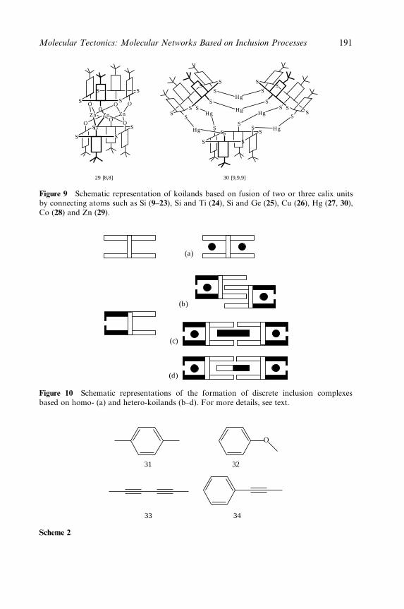
O
O
O
OO
O O
ZnZn Zn
O
S
S S
S
S S
SS
29 [8,8] 30 [9,9,9]
HgHg Hg
Hg
Hg
Hg
S
SS
SS
S
S
SS
S
S
SS
S
S
SS
S
S
SS
SS
S
Figure 9 Schematic representation of koilands based on fusion of two or three calix unitsby connecting atoms such as Si (9±23), Si and Ti (24), Si and Ge (25), Cu (26), Hg (27, 30),Co (28) and Zn (29).
(a)
(b)
(c)
(d)
Figure 10 Schematic representations of the formation of discrete inclusion complexesbased on homo- (a) and hetero-koilands (b±d). For more details, see text.
O
31
33
32
34
Scheme 2
Molecular Tectonics: Molecular Networks Based on Inclusion Processes 191
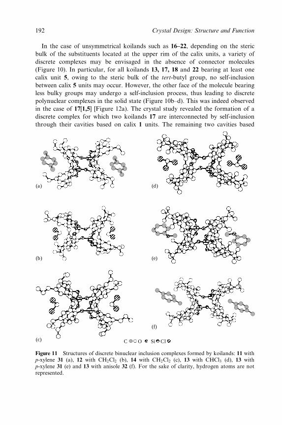
In the case of unsymmetrical koilands such as 16±22, depending on the steric
bulk of the substituents located at the upper rim of the calix units, a variety of
discrete complexes may be envisaged in the absence of connector molecules
(Figure 10). In particular, for all koilands 13, 17, 18 and 22 bearing at least one
calix unit 5, owing to the steric bulk of the tert-butyl group, no self-inclusion
between calix 5 units may occur. However, the other face of the molecule bearing
less bulky groups may undergo a self-inclusion process, thus leading to discrete
polynuclear complexes in the solid state (Figure 10b±d). This was indeed observed
in the case of 17[1,5] [Figure 12a). The crystal study revealed the formation of a
discrete complex for which two koilands 17 are interconnected by self-inclusion
through their cavities based on calix 1 units. The remaining two cavities based
(c)
(b)
(a)
(f)
C O Si Cl
(e)
(d)
Figure 11 Structures of discrete binuclear inclusion complexes formed by koilands: 11 withp-xylene 31 (a), 12 with CH2Cl2 (b), 14 with CH2Cl2 (c), 13 with CHCl3 (d), 13 withp-xylene 31 (e) and 13 with anisole 32 (f). For the sake of clarity, hydrogen atoms are notrepresented.
192 Crystal Design: Structure and Function
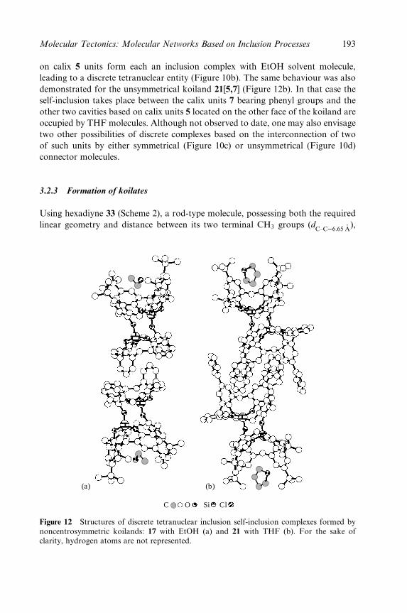
on calix 5 units form each an inclusion complex with EtOH solvent molecule,
leading to a discrete tetranuclear entity (Figure 10b). The same behaviour was also
demonstrated for the unsymmetrical koiland 21[5,7] (Figure 12b). In that case the
self-inclusion takes place between the calix units 7 bearing phenyl groups and the
other two cavities based on calix units 5 located on the other face of the koiland are
occupied by THF molecules. Although not observed to date, one may also envisage
two other possibilities of discrete complexes based on the interconnection of two
of such units by either symmetrical (Figure 10c) or unsymmetrical (Figure 10d)
connector molecules.
3.2.3 Formation of koilates
Using hexadiyne 33 (Scheme 2), a rod-type molecule, possessing both the required
linear geometry and distance between its two terminal CH3 groups (dC±C�6:65 ÊA
),
C O Si Cl
(a) (b)
Figure 12 Structures of discrete tetranuclear inclusion self-inclusion complexes formed bynoncentrosymmetric koilands: 17 with EtOH (a) and 21 with THF (b). For the sake ofclarity, hydrogen atoms are not represented.
Molecular Tectonics: Molecular Networks Based on Inclusion Processes 193
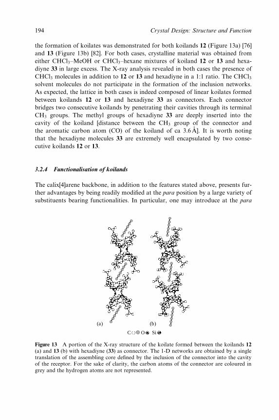
the formation of koilates was demonstrated for both koilands 12 (Figure 13a) [76]
and 13 (Figure 13b) [82]. For both cases, crystalline material was obtained from
either CHCl3±MeOH or CHCl3±hexane mixtures of koiland 12 or 13 and hexa-
diyne 33 in large excess. The X-ray analysis revealed in both cases the presence of
CHCl3 molecules in addition to 12 or 13 and hexadiyne in a 1:1 ratio. The CHCl3solvent molecules do not participate in the formation of the inclusion networks.
As expected, the lattice in both cases is indeed composed of linear koilates formed
between koilands 12 or 13 and hexadiyne 33 as connectors. Each connector
bridges two consecutive koilands by penetrating their cavities through its terminal
CH3 groups. The methyl groups of hexadiyne 33 are deeply inserted into the
cavity of the koiland [distance between the CH3 group of the connector and
the aromatic carbon atom (CO) of the koiland of ca 3.6 AÊ ]. It is worth noting
that the hexadiyne molecules 33 are extremely well encapsulated by two conse-
cutive koilands 12 or 13.
3.2.4 Functionalisation of koilands
The calix[4]arene backbone, in addition to the features stated above, presents fur-
ther advantages by being readily modi®ed at the para position by a large variety of
substituents bearing functionalities. In particular, one may introduce at the para
(a) (b)
O SiC
Figure 13 A portion of the X-ray structure of the koilate formed between the koilands 12(a) and 13 (b) with hexadiyne (33) as connector. The 1-D networks are obtained by a singletranslation of the assembling core de®ned by the inclusion of the connector into the cavityof the receptor. For the sake of clarity, the carbon atoms of the connector are coloured ingrey and the hydrogen atoms are not represented.
194 Crystal Design: Structure and Function
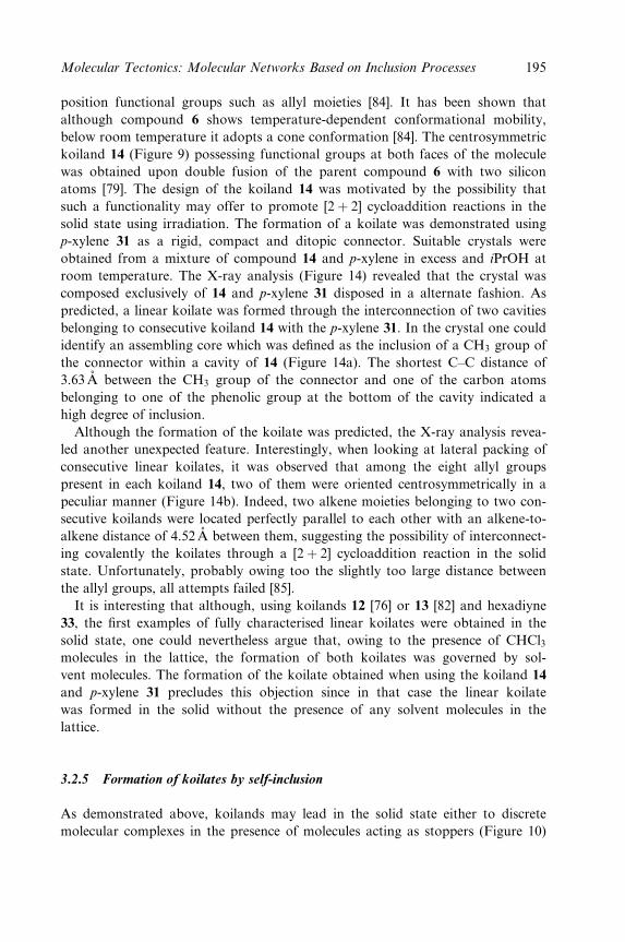
position functional groups such as allyl moieties [84]. It has been shown that
although compound 6 shows temperature-dependent conformational mobility,
below room temperature it adopts a cone conformation [84]. The centrosymmetric
koiland 14 (Figure 9) possessing functional groups at both faces of the molecule
was obtained upon double fusion of the parent compound 6 with two silicon
atoms [79]. The design of the koiland 14 was motivated by the possibility that
such a functionality may offer to promote [2� 2] cycloaddition reactions in the
solid state using irradiation. The formation of a koilate was demonstrated using
p-xylene 31 as a rigid, compact and ditopic connector. Suitable crystals were
obtained from a mixture of compound 14 and p-xylene in excess and iPrOH at
room temperature. The X-ray analysis (Figure 14) revealed that the crystal was
composed exclusively of 14 and p-xylene 31 disposed in a alternate fashion. As
predicted, a linear koilate was formed through the interconnection of two cavities
belonging to consecutive koiland 14 with the p-xylene 31. In the crystal one could
identify an assembling core which was de®ned as the inclusion of a CH3 group of
the connector within a cavity of 14 (Figure 14a). The shortest C±C distance of
3.63AÊ between the CH3 group of the connector and one of the carbon atoms
belonging to one of the phenolic group at the bottom of the cavity indicated a
high degree of inclusion.
Although the formation of the koilate was predicted, the X-ray analysis revea-
led another unexpected feature. Interestingly, when looking at lateral packing of
consecutive linear koilates, it was observed that among the eight allyl groups
present in each koiland 14, two of them were oriented centrosymmetrically in a
peculiar manner (Figure 14b). Indeed, two alkene moieties belonging to two con-
secutive koilands were located perfectly parallel to each other with an alkene-to-
alkene distance of 4.52AÊ between them, suggesting the possibility of interconnect-
ing covalently the koilates through a [2� 2] cycloaddition reaction in the solid
state. Unfortunately, probably owing too the slightly too large distance between
the allyl groups, all attempts failed [85].
It is interesting that although, using koilands 12 [76] or 13 [82] and hexadiyne
33, the ®rst examples of fully characterised linear koilates were obtained in the
solid state, one could nevertheless argue that, owing to the presence of CHCl3molecules in the lattice, the formation of both koilates was governed by sol-
vent molecules. The formation of the koilate obtained when using the koiland 14
and p-xylene 31 precludes this objection since in that case the linear koilate
was formed in the solid without the presence of any solvent molecules in the
lattice.
3.2.5 Formation of koilates by self-inclusion
As demonstrated above, koilands may lead in the solid state either to discrete
molecular complexes in the presence of molecules acting as stoppers (Figure 10)
Molecular Tectonics: Molecular Networks Based on Inclusion Processes 195

C O Si
(a) (b)
Figure 14 A portion of the X-ray structure of the koilate formed between the koiland 14and p-xylene 31 as connector. The 1-D network is obtained by a single translation of theassembling core de®ned by the inclusion of the connector into the cavity of the receptor (a)and a portion of the structure showing the lateral packing of linear koilates leading toparallel disposition of the allyl moieties (b). For the sake of clarity, the carbon atoms of theconnector are coloured in grey and the hydrogen atoms are not represented.
or to linear molecular networks in the presence of appropriate connectors
(Figure 4). Another alternative route to the formation of linear koilate may be
based on the use of self-complementary koilands possessing simultaneously two
divergent cavities and connecting moieties (Figure 4). Compound 14 ful®ls these
requirements. Indeed, the latter possesses two preorganised cavities as well as allyl
groups at both faces of the molecule which may act as connectors [86].
In the crystalline phase, the self-complementary koiland 14 forms a linear koi-
late through the interconnection of two cavities belonging to consecutive koilands
14 by van der Waals interactions (Figure 15a). The assembling core leading by a
single translation to the 1-D self-inclusion network was identi®ed as the inclusion
of one of the four allyl groups located at one of the two faces of the molecule 14
by one of the two cavities of the consecutive self-complementary compound
14. The shortest C±C distance between the terminal CH2 of the allyl group acting
as connector and carbon atoms of one of the aromatic moieties of the cavity
belonging to the next unit varied from 3.63 to 3.92AÊ , indicating a rather high
196 Crystal Design: Structure and Function
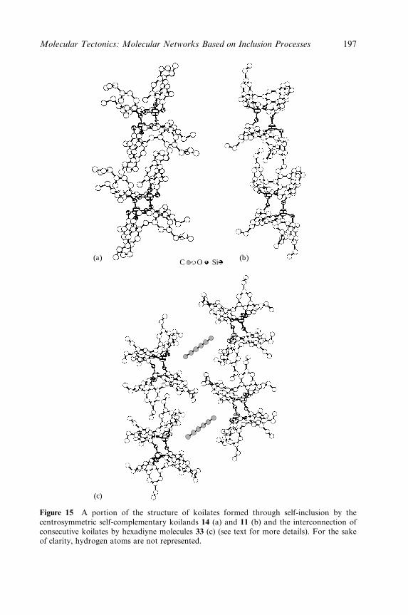
C O Si(a)
(c)
(b)
Figure 15 A portion of the structure of koilates formed through self-inclusion by thecentrosymmetric self-complementary koilands 14 (a) and 11 (b) and the interconnection ofconsecutive koilates by hexadiyne molecules 33 (c) (see text for more details). For the sakeof clarity, hydrogen atoms are not represented.
Molecular Tectonics: Molecular Networks Based on Inclusion Processes 197
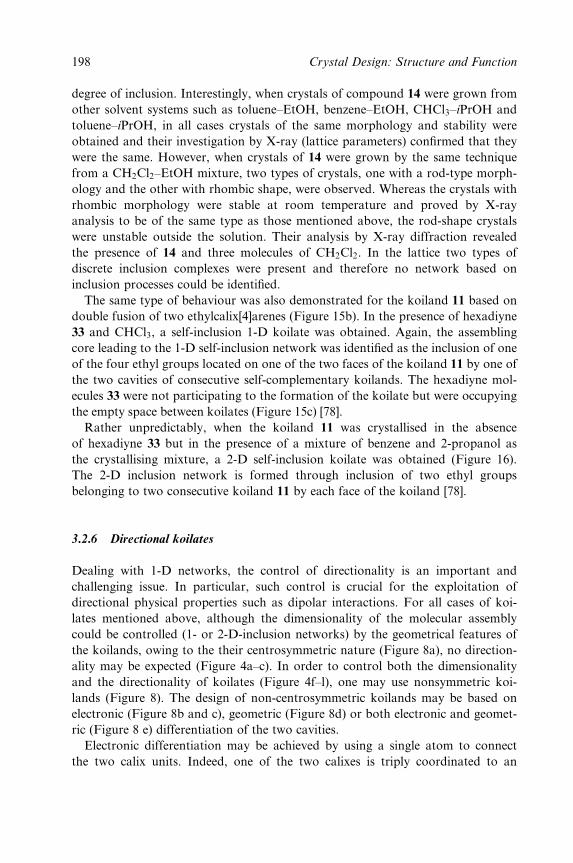
degree of inclusion. Interestingly, when crystals of compound 14 were grown from
other solvent systems such as toluene±EtOH, benzene±EtOH, CHCl3±iPrOH and
toluene±iPrOH, in all cases crystals of the same morphology and stability were
obtained and their investigation by X-ray (lattice parameters) con®rmed that they
were the same. However, when crystals of 14 were grown by the same technique
from a CH2Cl2±EtOH mixture, two types of crystals, one with a rod-type morph-
ology and the other with rhombic shape, were observed. Whereas the crystals with
rhombic morphology were stable at room temperature and proved by X-ray
analysis to be of the same type as those mentioned above, the rod-shape crystals
were unstable outside the solution. Their analysis by X-ray diffraction revealed
the presence of 14 and three molecules of CH2Cl2. In the lattice two types of
discrete inclusion complexes were present and therefore no network based on
inclusion processes could be identi®ed.
The same type of behaviour was also demonstrated for the koiland 11 based on
double fusion of two ethylcalix[4]arenes (Figure 15b). In the presence of hexadiyne
33 and CHCl3, a self-inclusion 1-D koilate was obtained. Again, the assembling
core leading to the 1-D self-inclusion network was identi®ed as the inclusion of one
of the four ethyl groups located on one of the two faces of the koiland 11 by one of
the two cavities of consecutive self-complementary koilands. The hexadiyne mol-
ecules 33 were not participating to the formation of the koilate but were occupying
the empty space between koilates (Figure 15c) [78].
Rather unpredictably, when the koiland 11 was crystallised in the absence
of hexadiyne 33 but in the presence of a mixture of benzene and 2-propanol as
the crystallising mixture, a 2-D self-inclusion koilate was obtained (Figure 16).
The 2-D inclusion network is formed through inclusion of two ethyl groups
belonging to two consecutive koiland 11 by each face of the koiland [78].
3.2.6 Directional koilates
Dealing with 1-D networks, the control of directionality is an important and
challenging issue. In particular, such control is crucial for the exploitation of
directional physical properties such as dipolar interactions. For all cases of koi-
lates mentioned above, although the dimensionality of the molecular assembly
could be controlled (1- or 2-D-inclusion networks) by the geometrical features of
the koilands, owing to the their centrosymmetric nature (Figure 8a), no direction-
ality may be expected (Figure 4a±c). In order to control both the dimensionality
and the directionality of koilates (Figure 4f±l), one may use nonsymmetric koi-
lands (Figure 8). The design of non-centrosymmetric koilands may be based on
electronic (Figure 8b and c), geometric (Figure 8d) or both electronic and geomet-
ric (Figure 8 e) differentiation of the two cavities.
Electronic differentiation may be achieved by using a single atom to connect
the two calix units. Indeed, one of the two calixes is triply coordinated to an
198 Crystal Design: Structure and Function
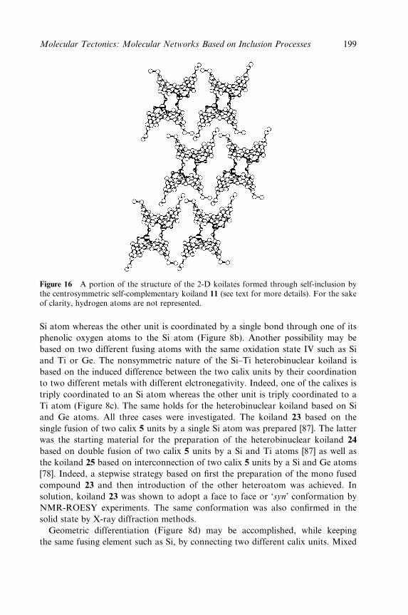
Figure 16 A portion of the structure of the 2-D koilates formed through self-inclusion bythe centrosymmetric self-complementary koiland 11 (see text for more details). For the sakeof clarity, hydrogen atoms are not represented.
Si atom whereas the other unit is coordinated by a single bond through one of its
phenolic oxygen atoms to the Si atom (Figure 8b). Another possibility may be
based on two different fusing atoms with the same oxidation state IV such as Si
and Ti or Ge. The nonsymmetric nature of the Si±Ti heterobinuclear koiland is
based on the induced difference between the two calix units by their coordination
to two different metals with different elctronegativity. Indeed, one of the calixes is
triply coordinated to an Si atom whereas the other unit is triply coordinated to a
Ti atom (Figure 8c). The same holds for the heterobinuclear koiland based on Si
and Ge atoms. All three cases were investigated. The koiland 23 based on the
single fusion of two calix 5 units by a single Si atom was prepared [87]. The latter
was the starting material for the preparation of the heterobinuclear koiland 24
based on double fusion of two calix 5 units by a Si and Ti atoms [87] as well as
the koiland 25 based on interconnection of two calix 5 units by a Si and Ge atoms
[78]. Indeed, a stepwise strategy based on ®rst the preparation of the mono fused
compound 23 and then introduction of the other heteroatom was achieved. In
solution, koiland 23 was shown to adopt a face to face or `syn' conformation by
NMR-ROESY experiments. The same conformation was also con®rmed in the
solid state by X-ray diffraction methods.
Geometric differentiation (Figure 8d) may be accomplished, while keeping
the same fusing element such as Si, by connecting two different calix units. Mixed
Molecular Tectonics: Molecular Networks Based on Inclusion Processes 199
koilands 16±22, based on the double fusion of two different calix units by two Si
atoms, were prepared. The general strategy for the preparation of nonsymmetric koi-
landswasbasedonacombinatorialapproach.Upontreatmentofacombinationoftwo
different calix[4]arenes (X,Y) (X � Y � 1±7] with base, followed by reaction with
SiCl4, as expected, three different koilands [X±X], [Y±Y] of the homo type (centro-
symmetric) and [X±Y] of the hetero type (noncentrosymmetric) were obtained [88].
In solution, as expected, 29Si NMR studies revealed the presence of two signals
for all noncentrosymmetric heterodimers, whereas for the centrosymmetric koi-
lands a unique signal was observed.
The ability of noncentrosymmetric koilands 22±24 to form discrete binuclear
inclusion complexes was demonstrated in the solid state by X-ray diffraction
methods on single crystals [78]. Inclusion complexes for both the doubly fused
koiland 22 [Figure 17a) and the mono fused koiland 23 (Figure 17b) with CH2Cl2were obtained. In the presence of phenylpropyne 34, both koilands 23 (Figure 17c)
and 24 (Figure 17d) led to the formation of binuclear inclusion complexes.
The third possibility, consisting in using two different calix derivatives and two
different atoms for their fusion, has not yet been exploited.
C O Si Cl
C O Si Cl C O Si Ti
C O Si
(a) (c)
(b) (d)
Figure 17 Structures of discrete binuclear inclusion complexes formed by noncentrosym-metric koilands: 22 with CH2Cl2 (a), mono fused koiland 23 with CH2Cl2 (b), mono fusedkoiland 23 with phenylpropyne 34 (c) and heterobinuclear koiland 24 with CH2Cl2 (d) (seetext for more details). For the sake of clarity, hydrogen atoms are not represented.
200 Crystal Design: Structure and Function
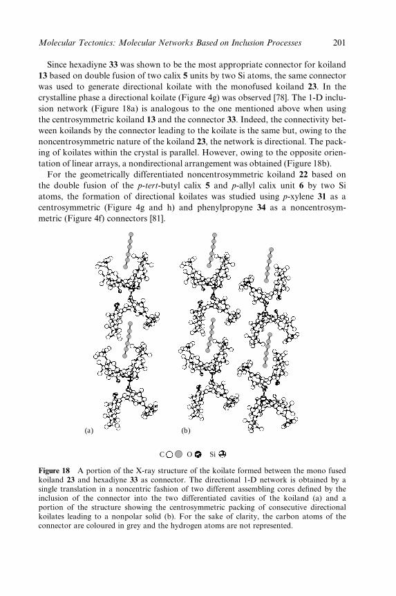
Since hexadiyne 33 was shown to be the most appropriate connector for koiland
13 based on double fusion of two calix 5 units by two Si atoms, the same connector
was used to generate directional koilate with the monofused koiland 23. In the
crystalline phase a directional koilate (Figure 4g) was observed [78]. The 1-D inclu-
sion network (Figure 18a) is analogous to the one mentioned above when using
the centrosymmetric koiland 13 and the connector 33. Indeed, the connectivity bet-
ween koilands by the connector leading to the koilate is the same but, owing to the
noncentrosymmetric nature of the koiland 23, the network is directional. The pack-
ing of koilates within the crystal is parallel. However, owing to the opposite orien-
tation of linear arrays, a nondirectional arrangement was obtained (Figure 18b).
For the geometrically differentiated noncentrosymmetric koiland 22 based on
the double fusion of the p-tert-butyl calix 5 and p-allyl calix unit 6 by two Si
atoms, the formation of directional koilates was studied using p-xylene 31 as a
centrosymmetric (Figure 4g and h) and phenylpropyne 34 as a noncentrosym-
metric (Figure 4f) connectors [81].
C
(a) (b)
O Si
Figure 18 A portion of the X-ray structure of the koilate formed between the mono fusedkoiland 23 and hexadiyne 33 as connector. The directional 1-D network is obtained by asingle translation in a noncentric fashion of two different assembling cores de®ned by theinclusion of the connector into the two differentiated cavities of the koiland (a) and aportion of the structure showing the centrosymmetric packing of consecutive directionalkoilates leading to a nonpolar solid (b). For the sake of clarity, the carbon atoms of theconnector are coloured in grey and the hydrogen atoms are not represented.
Molecular Tectonics: Molecular Networks Based on Inclusion Processes 201
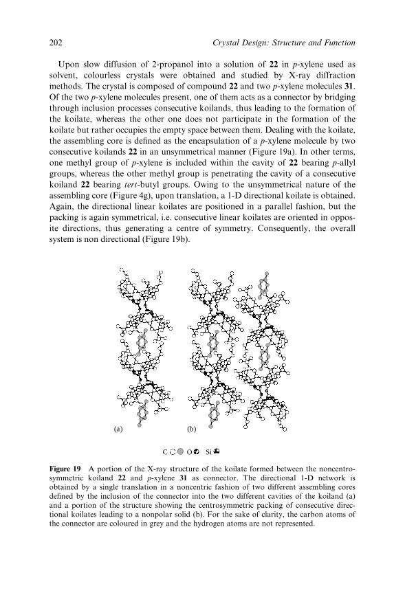
Upon slow diffusion of 2-propanol into a solution of 22 in p-xylene used as
solvent, colourless crystals were obtained and studied by X-ray diffraction
methods. The crystal is composed of compound 22 and two p-xylene molecules 31.
Of the two p-xylene molecules present, one of them acts as a connector by bridging
through inclusion processes consecutive koilands, thus leading to the formation of
the koilate, whereas the other one does not participate in the formation of the
koilate but rather occupies the empty space between them. Dealing with the koilate,
the assembling core is de®ned as the encapsulation of a p-xylene molecule by two
consecutive koilands 22 in an unsymmetrical manner (Figure 19a). In other terms,
one methyl group of p-xylene is included within the cavity of 22 bearing p-allyl
groups, whereas the other methyl group is penetrating the cavity of a consecutive
koiland 22 bearing tert-butyl groups. Owing to the unsymmetrical nature of the
assembling core (Figure 4g), upon translation, a 1-D directional koilate is obtained.
Again, the directional linear koilates are positioned in a parallel fashion, but the
packing is again symmetrical, i.e. consecutive linear koilates are oriented in oppos-
ite directions, thus generating a centre of symmetry. Consequently, the overall
system is non directional (Figure 19b).
(a) (b)
C O Si
Figure 19 A portion of the X-ray structure of the koilate formed between the noncentro-symmetric koiland 22 and p-xylene 31 as connector. The directional 1-D network isobtained by a single translation in a noncentric fashion of two different assembling coresde®ned by the inclusion of the connector into the two different cavities of the koiland (a)and a portion of the structure showing the centrosymmetric packing of consecutive direc-tional koilates leading to a nonpolar solid (b). For the sake of clarity, the carbon atoms ofthe connector are coloured in grey and the hydrogen atoms are not represented.
202 Crystal Design: Structure and Function
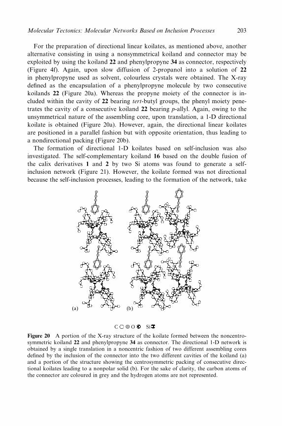
For the preparation of directional linear koilates, as mentioned above, another
alternative consisting in using a nonsymmetrical koiland and connector may be
exploited by using the koiland 22 and phenylpropyne 34 as connector, respectively
(Figure 4f). Again, upon slow diffusion of 2-propanol into a solution of 22
in phenylpropyne used as solvent, colourless crystals were obtained. The X-ray
de®ned as the encapsulation of a phenylpropyne molecule by two consecutive
koilands 22 (Figure 20a). Whereas the propyne moiety of the connector is in-
cluded within the cavity of 22 bearing tert-butyl groups, the phenyl moiety pene-
trates the cavity of a consecutive koiland 22 bearing p-allyl. Again, owing to the
unsymmetrical nature of the assembling core, upon translation, a 1-D directional
koilate is obtained (Figure 20a). However, again, the directional linear koilates
are positioned in a parallel fashion but with opposite orientation, thus leading to
a nondirectional packing (Figure 20b).
The formation of directional 1-D koilates based on self-inclusion was also
investigated. The self-complementary koiland 16 based on the double fusion of
the calix derivatives 1 and 2 by two Si atoms was found to generate a self-
inclusion network (Figure 21). However, the koilate formed was not directional
because the self-inclusion processes, leading to the formation of the network, take
(a) (b)
C O Si
Figure 20 A portion of the X-ray structure of the koilate formed between the noncentro-symmetric koiland 22 and phenylpropyne 34 as connector. The directional 1-D network isobtained by a single translation in a noncentric fashion of two different assembling coresde®ned by the inclusion of the connector into the two different cavities of the koiland (a)and a portion of the structure showing the centrosymmetric packing of consecutive direc-tional koilates leading to a nonpolar solid (b). For the sake of clarity, the carbon atoms ofthe connector are coloured in grey and the hydrogen atoms are not represented.
Molecular Tectonics: Molecular Networks Based on Inclusion Processes 203
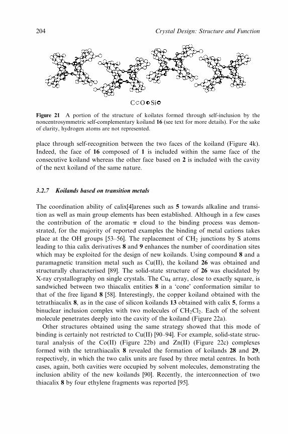
C O Si
Figure 21 A portion of the structure of koilates formed through self-inclusion by thenoncentrosymmetric self-complementary koiland 16 (see text for more details). For the sakeof clarity, hydrogen atoms are not represented.
place through self-recognition between the two faces of the koiland (Figure 4k).
Indeed, the face of 16 composed of 1 is included within the same face of the
consecutive koiland whereas the other face based on 2 is included with the cavity
of the next koiland of the same nature.
3.2.7 Koilands based on transition metals
The coordination ability of calix[4]arenes such as 5 towards alkaline and transi-
tion as well as main group elements has been established. Although in a few cases
the contribution of the aromatic p cloud to the binding process was demon-
strated, for the majority of reported examples the binding of metal cations takes
place at the OH groups [53±56]. The replacement of CH2 junctions by S atoms
leading to thia calix derivatives 8 and 9 enhances the number of coordination sites
which may be exploited for the design of new koilands. Using compound 8 and a
paramagnetic transition metal such as Cu(II), the koiland 26 was obtained and
structurally characterised [89]. The solid-state structure of 26 was elucidated by
X-ray crystallography on single crystals. The Cu4 array, close to exactly square, is
sandwiched between two thiacalix entities 8 in a `cone' conformation similar to
that of the free ligand 8 [58]. Interestingly, the copper koiland obtained with the
tetrathiacalix 8, as in the case of silicon koilands 13 obtained with calix 5, forms a
binuclear inclusion complex with two molecules of CH2Cl2. Each of the solvent
molecule penetrates deeply into the cavity of the koiland (Figure 22a).
Other structures obtained using the same strategy showed that this mode of
binding is certainly not restricted to Cu(II) [90±94]. For example, solid-state struc-
tural analysis of the Co(II) (Figure 22b) and Zn(II) (Figure 22c) complexes
formed with the tetrathiacalix 8 revealed the formation of koilands 28 and 29,
respectively, in which the two calix units are fused by three metal centres. In both
cases, again, both cavities were occupied by solvent molecules, demonstrating the
inclusion ability of the new koilands [90]. Recently, the interconnection of two
thiacalix 8 by four ethylene fragments was reported [95].
204 Crystal Design: Structure and Function
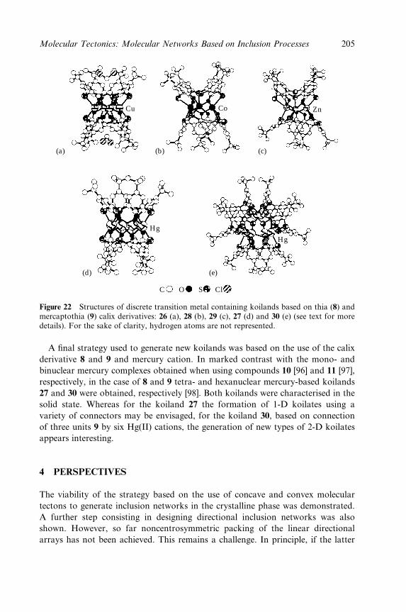
ClC O S
Cu
Hg
Hg
Co Zn
(a) (b)
(d) (e)
(c)
Figure 22 Structures of discrete transition metal containing koilands based on thia (8) andmercaptothia (9) calix derivatives: 26 (a), 28 (b), 29 (c), 27 (d) and 30 (e) (see text for moredetails). For the sake of clarity, hydrogen atoms are not represented.
A ®nal strategy used to generate new koilands was based on the use of the calix
derivative 8 and 9 and mercury cation. In marked contrast with the mono- and
binuclear mercury complexes obtained when using compounds 10 [96] and 11 [97],
respectively, in the case of 8 and 9 tetra- and hexanuclear mercury-based koilands
27 and 30 were obtained, respectively [98]. Both koilands were characterised in the
solid state. Whereas for the koiland 27 the formation of 1-D koilates using a
variety of connectors may be envisaged, for the koiland 30, based on connection
of three units 9 by six Hg(II) cations, the generation of new types of 2-D koilates
appears interesting.
4 PERSPECTIVES
The viability of the strategy based on the use of concave and convex molecular
tectons to generate inclusion networks in the crystalline phase was demonstrated.
A further step consisting in designing directional inclusion networks was also
shown. However, so far noncentrosymmetric packing of the linear directional
arrays has not been achieved. This remains a challenge. In principle, if the latter
Molecular Tectonics: Molecular Networks Based on Inclusion Processes 205

point of concern could be solved, the strategy presented here may be used to
generate polar solids of fundamental importance Furthermore, in terms of appli-
cations, the design of predicted polar solids is important since one may then
exploit vectorial physical properties.
ACKNOWLEDGEMENTS
This work was supported by the Universite Louis Pasteur, Institut Universitaire
de France and Centre National de la Recherche Scienti®que. Thanks are also due
to Dr X. Delaigue, Dr F. Hajek and N. Kyritsakas-Gruber.
REFERENCES
1. A. Gavezzotti, Acc. Chem. Res., 27, 309 (1994).2. J. D. Dunitz, Pure Appl. Chem., 63, 177 (1991).3. J.-M. Lehn, Supramolecular Chemistry, Concepts and Perspectives, VCH, Weinheim,
1995.4. M. Simard, D. Su, J. D. Wuest, J. Am. Chem. Soc., 113, 4696 (1991).5. G. R. Desiraju, Angew. Chem., Int. Ed. Engl., 34, 2311 (1995).6. M. C. Etter, Acc. Chem. Res., 23, 120 (1990).7. G. M. Whitesides, J. P. Mathias, T. Seto, Science, 254, 1312 (1991).8. F. W. Fowler, J. W. Lauher, J. Am. Chem. Soc., 115, 5991 (1993).9. J. S., Lindsey, New J. Chem., 15, 153 (1991).
10. D. S. Lawrence, T. Jiang, M. Levett, Chem. Rev., 95, 2229 (1995).11. X. Delaigye, E. Graf, F. Hajek, M. W. Hosseini, J. -M. Planeix in NATO ASI Series,
Eds. G. Tsoucaris, J. L. Atwood, J. Lipkowski, Series C, Vol. 480, Kluwer, Dordrecht,1996, p. 159.
12. D. Philp, J. F. Stoddart, Angew. Chem., Int. Ed. Engl., 35, 1155 (1996).13. S. Mann, Nature, 365, 499 (1993).14. C. B. AakeroÈy, K. R. Seddon, Chem. Soc. Rev., 22, 397 (1993); S. Subramanian, M. J.
Zaworotko, Coord. Chem. Rev., 137, 357 (1994); D. Braga, F. Grepioni, Acc. Chem.
Res., 27, 51 (1994); V. A. Russell, M. D. Ward, Chem. Mater., 8, 1654 (1996).15. R. Robson, in Comprehensive Supramolecular Chemistry, Eds J. L. Atwood, J. E. D.
Davies, D. D. MacNicol, F. VoÈgtle, Pergamon Press, Oxford, Vol. 6 (Eds D. D. Mac-Nicol, F. Toda, R. Bishop), 1996, p. 733.
16. A. J. Blake, N. R. Champness, P. Hubberstey, W.-S. Li, M. A. Withersby, M. SchoÈder,Coord. Chem. Rev., 183, 117 (1999).
17. O. M. Yaghi, H. Li, B. Chen, C. Davis, D. Richardson, T. L. Groy, Acc. Chem. Res.,31, 474 (1998).
18. M. W. Hosseini, in NATO ASI Series, Eds D. Braga, F. Grepiono, G. Orpen, Series C,Vol. 538, Kluwer, Dordrecht, 1999, p. 181.
19. B. Moulton, M. J. Zaworotko, Chem. Rev., 101, 1629 (2001).20. G. Brand, M. W. Hosseini, R. Ruppert, A. De Cian, J. Fischer, N. Kyritsakas, New
J. Chem., 19, 9 (1995).21. M. W. Hosseini, R. Ruppert, P. Schaeffer, A. De Cian, N. Kyritsakas, J. Fischer,
J. Chem. Soc. Chem. Commun., 2135 (1994).
206 Crystal Design: Structure and Function
22. M. W. Hosseini, G. Brand, P. Schaeffer, R. Ruppert, A. De Cian, J. Fischer, Tetrahe-
dron Lett., 37, 1405 (1996).23. G. Brand, M. W. Hosseini, O. FeÂlix, P. Schaeffer, R. Ruppert, in Magnetism: a Supra-
molecular Function, Ed. O. Kahn, NATO ASI Series, Series C, Vol. 484, Kluwer, Dor-drecht, 1996, p. 129.
24. O. FeÂlix, M. W. Hosseini, A. De Cian, J. Fischer, Angew. Chem., Int. Ed. Engl., 36, 102(1997).
25. O. FeÂlix, M. W. Hosseini, A. De Cian, J. Fischer, Tetrahedron Lett., 38, 175 (1997).26. O. FeÂlix, M. W. Hosseini, A. De Cian, J. Fischer, Tetrahedron Lett., 38, 1933 (1997).27. O. FeÂlix, M. W. Hosseini, A. De Cian, J. Fischer, New J. Chem., 21, 285 (1997).28. O. FeÂlix, M. W. Hosseini, A. De Cian, J. Fischer, New J. Chem., 22, 1389 (1998).29. O. FeÂlix, M. W. Hosseini, A. De Cian, J. Fischer, Chem. Commun., 281 (2000).30. D. Braga, L. Maini F. Grepioni, A. De Cian, O. FeÂlix, J. Fischer, M. W. Hosseini, New
J. Chem., 24, 547 (2000).31. O. FeÂlix, M. W. Hosseini, A. De Cian, Solid State Sci., 3, 789 (2001).32. S. Ferlay, O. FeÂlix, M. W. Hosseini, J.-M. Planeix, N. Kyritsakas, Chem. Commun., in
press (2002).33. C. Kaes, M. W. Hosseini, C. E. F. Rickard, B. W. Skelton, A. White, Angew. Chem.,
Int. Ed. Engl., 37, 920 (1998).34. G. Mislin, E. Graf, M. W. Hosseini, A. De Cian, N. Kyritsakas, J. Fischer, Chem.
Commun., 2545 (1998).35. M. LoõÈ, M. W. Hosseini, A. Jouaiti, A. De Cian, J. Fischer, Eur. J. Inorg. Chem., 1981
(1999).36. M. LoõÈ, E. Graf, M. W. Hosseini, A. De Cian, J. Fischer, Chem. Commun., 603 (1999).37. C. Klein, E. Graf, M. W. Hosseini, A. De Cian, J. Fischer, Chem. Commun., 239
(2000).38. H. Akdas, E. Graf, M. W. Hosseini, A. De Cian, J. McB. Harrow®eld, Chem. Com-
mun., 2219 (2000).39. A. Jouaiti, M. W. Hosseini, A. De Cian, Chem. Commun., 1863 (2000).40. B. Schmaltz, A. Jouaiti, M. W. Hosseini, A. De Cian, Chem. Commun., 1242 (2001).41. A. Jouaiti, V. Jullien, M. W. Hosseini J.-M. Planeix, A. De Cian, Chem. Commun.,
1114 (2001).42. C. Klein, E. Graf, M. W. Hosseini, A. De Cian, J. Fischer, New J. Chem, 25, 207 (2001).43. S.Ferlay, S. Koenig, M. W. Hosseini, J. Pansanel, A. De Cian N. Kyritsakas, Chem.
Commun., 218 (2002).44. X. Delaigue, M. W. Hosseini, A. De Cian, J. Fischer, E. Leize, S. Kieffer, A. Van
Dorsselaer, Tetrahedron Lett., 34, 3285 (1993).45. X. Delaigue, M. W. Hosseini, R. Graff, J.-P. Kintzinger, J. Raya, Tetrahedron Lett.,
35, 1711 (1994).46. X. Delaigue, E. Graf, F. Hajek, M. W. Hosseini, J.-M. Planeix, in Crystallography of
Supramolecular Compounds, Eds G. Tsoucaris, J. L. Atwood, J. Lipkowski, NATO ASI
Series, Series C, Vol. 480, Kluwer, Dordrecht, 1996, p. 159.47. M. W. Hosseini, A. De Cian, Chem. Commun., 727 (1998).48. C. J. Pedersen, Angew. Chem., Int. Ed. Engl. 27, 1021 (1988).49. D. J. Cram, Angew. Chem., Int. Ed. Engl., 27, 1009 (1988).50. J.-M. Lehn, Angew. Chem., Int. Ed. Engl., 27, 89 (1988).51. H. M. Powell, J. Chem. Soc., 61 (1948).52. Molecular Inclusion and Molecular Recognition. Clathtrates I and II. Topics in Current
Chemistry, Ed., E. Weber, Springer, New York, Vols 140 and 149, 1987 and 1988.53. C. D. Gutsche, Calixarenes, Monographs in Supramolecular Chemistry, Ed. J. F. Stod-
dart, Royal Society of Chemistry, London, 1989; C. D. Gutsche, Calixarenes Revisited,
Molecular Tectonics: Molecular Networks Based on Inclusion Processes 207
Monographs in Supramolecular Chemistry, Ed. J. F. Stoddart, Royal Society of Chemis-try, London, 1998.
54. Calixarenes. A Versatile Class of Macrocyclic Compounds, Ed. J. Vicens and V. BoÈh-mer, Kluwer, Dordrecht, 1991.
55. V. BoÈhmer, Angew. Chem., Int. Ed. Engl., 34, 713 (1995).56. Calixarenes 2001, Eds J. Vicens, Z. Asfari, J. M. Harrow®eld, V. BoÈhmer, Kluwer,
Dordrecht, 2001.57. H. Kumagai, M. Hasegawa, S. Miyanari, Y. Sugawa, Y. Sato, T. Hori, S. Ueda,
H. Kamiyama, S. Miyano, Tetrahedron Lett., 38, 3971 (1997), T. Sone, Y. Ohba,K. Moriya, H. Kumada, K. Ito, Tetrahedron, 53, 10689 (1997).
58. H. Akdas, L. Bringel, E. Graf, M. W. Hosseini, G. Mislin, J. Pansanel, A. De Cian, J.Fischer, Tetrahedron Lett., 39, 2311 (1998).
59. M. W. Hosseini, Calixarene Molecules for Separation, Eds G. J. Lumetta, R. D.Rogers, A. S. Gopalan, ACS Symposium Series, Vol. 557, American Chemical Society,Washington, DC, 2000, p. 296.
60. M. W. Hosseini, in Calixarenes 2001, Eds J. Vicens, Z. Asfari, J. M. Harrow®eld,V. BoÈhmer, Kluwer, Dordrecht, 2001, pp. 110±129.
61. P. Rao, M. W. Hosseini, A. De Cian, J. Fischer, Chem. Commun., 2169 (1999).62. C. D. Gutsche, B. Dhawan, K. H. No, R. Muthukrishnan, J. Am. Chem. Soc., 103,
3782 (1981); G. D. Andreetti, R. Ungaro, A. Pochini, Chem. Commun., 1005 (1979);R. Ungaro, A. Pochini, G. D. Andreetti, P. Domiano, J. Chem. Soc., Perkin Trans. 2,197 (1985); M. Coruzzi, G. D. Andreetti, V. Bocchi, A. Pochini, R. Ungaro, J. Chem.
Soc., Perkin Trans. 2, 1133 (1982).63. M. M. Olmstead, G. Sigel, H. Hope, X. Xu, P. Power, J. Am. Chem. Soc., 107, 8087
(1985); F. Corazza, C. Floriani, A. Chiesti-Villa, C. Guastini, Chem. Commun., 1083(1990); J. L. Atwood, S. G. Bott, C. Jones, C. L. Raston, Chem.Commun., 1349 (1992);J. L. Atwood, P. C. Junk, S. M. Lawrence, C. L. Raston, Supramol. Chem., 7, 15(1996).
64. D. Kraft, J.-D. van Loon, M. Owens, W. Verboom, W. Vogt, M. A. McKervey,V. BoÈhmer, D. N. Reinhoudt, Tetrahedron Lett., 31, 4941 (1990); J.-D. van Loon,D. Kraft, M. J. K. AnkoneÂ, W. Verboom, S. Harkema, V. BoÈhmer, D. N. Reinhoudt,J. Org. Chem., 55, 5176 (1990); P. Schmidtt, P. D. Beer, M. G. B. Drew, P. D. Sheen,Angew. Chem., Int. Ed. Engl., 36, 1840 (1997).
65. P. D. Beer, A. D. Keefe, A. M. Z. Slawin, D. J. Williams, J. Chem Soc., Dalton Trans.,3675 (1990).
66. C. D. Gutsche, M. Iqbal, Org. Synth., 68, 234 (1989).67. C. D. Gutsche, J. A. Levine, J. Am. Chem. Soc., 104, 2652 (1982).68. C. D. Gutsche, K. C. Nam, J. Am. Chem. Soc, 110, 6153 (1988).69. C. D. Gutsche, K. H. No, J. Org. Chem., 47, 2708 (1982); K. H. No, C. D. Gutsche,
J. Org. Chem., 47, 2713 (1982).70. M. Almi, A. Arduini, A. Casnati, A. Pochini, R. Ungaro, Tetrahedron, 45, 2177 (1989).71. R. K. Juneja, K. D. Robinson, C. P Johnson, J. L. Atwood, J. Am. Chem. Soc, 115,
3818 (1993).72. A. Arduini, A. Pochini, A. Rizzi, A. R. Sicuri, F. Ugozzoli, R. Ungaro, Tetrahedron,
48, 905 (1992).73. C. D. Gutsche, J. A. Levine, J. Am. Chem. Soc, 104, 2653 (1982).74. B. Yao, J. Bassus, R. Lamartine, New J. Chem., 20, 913 (1996).75. B. Dhawan, S. I. Chen, C. D. Gutsche, Makromol. Chem., 188, 921 (1987).76. J. Martz, E. Graf, M. W. Hosseini, A. De Cian, J. Fischer, J. Mater. Chem, 8, 2331
(1998).77. F. Hajek, E. Graf, M. W. Hosseini, Tetrahedron Lett., 37, 1409 (1996).
208 Crystal Design: Structure and Function
78. J. Martz, E. Graf, M. W. Hosseini, A. De Cian, to be published.79. F. Hajek, E. Graf, M. W. Hosseini, A. De Cian, J. Fischer, Angew. Chem., Int. Ed.
Engl., 36, 1760 (1997).80. F. Hajek, E. Graf, M. W. Hosseini, A. De Cian, J. Fischer, Tetrahedron Lett., 38, 4555
(1997).81. J. Martz, E. Graf, M. W. Hosseini, A. De Cian, J. Fischer, J. Chem. Soc., Dalton
Trans., 3791 (2000).82. F. Hajek, E. Graf, M. W. Hosseini, X. Delaigue, A. De Cian, J. Fischer, Tetrahedron
Lett., 37, 1401 (1996).83. M. Perrin, F. Gharnati, D. Oehler, R. Perrin, S. Lecocq, J. Inclus. Phenom., 14, 257
(1992).84. C. D. Gutsche, J. A. Levine, J. Am. Chem. Soc., 104, 2653 (1982).85. F. Hajek, B. M. Foxman, M. W. Hosseini, unpublished results.86. F. Hajek, E. Graf, M. W. Hosseini, A. De Cian, J. Fischer, Cryst. Eng. 1, 79 (1998).87. X. Delaigue, M. W. Hosseini, E. Leize, S. Kieffer, A. van Dorsselaer, Tetrahedron
Lett., 34, 7561 (1993).88. F. Hajek, E. Graf, M. W. Hosseini, A. De Cian, J. Fischer, Tetrahedron Lett., 38, 4555
(1997).89. G. Mislin, E. Graf, M. W. Hosseini, A. Bilyk, A. K. Hall, J. McB. Harrow®eld, B. W.
Skelton, A. H. White, Chem. Commun., 373 (1999).90. A. Bilyk, A. K. Hall, J. M. Harrow®eld, M. W. Hosseini, G. Mislin, B. W. Skelton,
C. Taylor, A. White, Eur. J.Inorg. Chem., 823 (2000).91. A. Bilyk, A. K. Hall, J. M. Harrow®eld, M. W. Hosseini, B. W. Skelton, A. White,
Aust. J. Chem, 53, 895 (2000).92. H. Akdas, E. Graf, M. W. Hosseini, A. De Cian, J. M. Harrow®eld, Chem. Commun.,
2219 (2000).93. Z. Asfari, A. Bilyk, J. W. C. Dunlop, A. K. Hall J. M. Harrow®eld, M. W. Hosseini,
B. W. Skelton, A. H. White, Angew. Chem., Int. Ed. Engl., 40, 721 (2001).94. A. Bilyk, A. K. Hall, J. M. Harrow®eld, M. W. Hosseini, B. W. Skelton, A. H. White,
Inorg. Chem., 40, 672 (2001).95. S. E. Matthews, V. Felix, M. G. B. Drew, P. D. Beer, New J. Chem, 25, 1355, (2001).96. X. Delaigue, J. McB. Harrow®eld, M. W. Hosseini, A. De Cian, J. Fischer, N. Kyritsa-
kas, Chem. Commun., 1579 (1994).97. X. Delaigue, M. W. Hosseini, A. De Cian, N. Kyritsakas, J. Fischer, Chem. Commun.,
609 (1995).98. H. Akdas, E. Graf, M. W. Hosseini, A. De Cian, A. Bilyk, B. W. Skelton, G. A.
Koutsantonis, I. Murray, J. M. Harrow®eld, A. H. White, Chem Commun., 1042(2002).
Molecular Tectonics: Molecular Networks Based on Inclusion Processes 209
Chapter 5
Layered Materials by Design: 2DCoordination Polymeric NetworksContaining Large Cavities/Channels
KUMAR BIRADHA
Indian Institute of Technology Kharagpur, Kharagpur, India
MAKOTO FUJITA
The University of Tokyo, Tokyo, Japan
1 INTRODUCTION
Crystal engineering deals with the engineering of crystalline materials with desired
physical and chemical properties and is a multidisciplinary area as it has implica-
tions for materials chemistry, supramolecular chemistry, molecular recognition and
biology [1]. In general, the properties of crystalline materials are the result of the
arrangement or assembly of molecules in a crystal lattice. Therefore, the properties
of a solid can be engineered by arranging or assembling molecules in a required
fashion through intermolecular interactions such as hydrogen or coordination
bonds [2]. Currently, crystal engineering with coordination bonds is an attractive
area of research owing to the inherent stability of coordination bonds and also to
the versatility of coordination modes of transition metal atoms [3]. Porosity is one
of the most targeted properties of coordination polymers as channels/cavities exist
in the coordination networks [4]. Owing to the existence of such large channels/
cavities, polymeric coordination materials are expected to mimic the functions of
Crystal Design: Structure and Function. Volume 7Edited by Gautam R. Desiraju
Copyright 2003 John Wiley & Sons, Ltd.ISBN: 0-470-84333-0
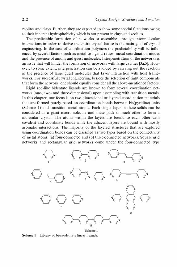
zeolites and clays. Further, they are expected to show some special functions owing
to their inherent hydrophobicity which is not present in clays and zeolites.
The predictable formation of networks or assemblies through intermolecular
interactions in order to derive the entire crystal lattice is the main goal of crystal
engineering. In the case of coordination polymers the predictability will be in¯u-
enced by several factors such as metal to ligand ratios, metal coordination modes
and the presence of anions and guest molecules. Interpenetration of the networks is
an issue that will hinder the formation of networks with large cavities [3a,5]. How-
ever, to some extent, interpenetration can be avoided by carrying out the reaction
in the presence of large guest molecules that favor interaction with host frame-
works. For successful crystal engineering, besides the selection of right components
that form the network, one should equally consider all the above-mentioned factors.
Rigid rod-like bidentate ligands are known to form several coordination net-
works (one-, two- and three-dimensional) upon assembling with transition metals.
In this chapter, our focus is on two-dimensional or layered coordination materials
that are formed purely based on coordination bonds between bis(pyridine) units
(Scheme 1) and transition metal atoms. Each single layer in these solids can be
considered as a giant macromolecule and these pack on each other to form a
molecular crystal. The atoms within the layers are bound to each other with
covalent and coordinate bonds while the adjacent layers are bound with mostly
aromatic interactions. The majority of the layered structures that are explored
using coordination bonds can be classi®ed as two types based on the connectivity
of metal atoms: (a) four-connected and (b) three-connected networks. Square grid
networks and rectangular grid networks come under the four-connected type
N N N N
N
N
N
NN
N
N
N
N
N
N
1 2
4
3
7
8
9
Scheme 1
N
N NN
N5 6
Scheme 1 Library of bi-exodentate linear ligands.
212 Crystal Design: Structure and Function

while honeycomb, brick wall, bilayer and herringbone networks come under the
three-connected type. Three-dimensional networks can also be generated from
two-dimensional networks either by the interpenetration of the layers or by con-
necting the metal centers of the adjacent layers.
2 SQUARE GRIDS
All the ligands 1±9 except 6 were known to assemble into square grid networks with
M(II) salts. The dimensions of the square grid cavities, depending on the length of
the ligands, can vary from 7 to 20 AÊ . In networks the metal atom adopts octahedral
geometry with four ligands at equatorial positions and two counteranions or water
molecules at axial positions. In most of these grid networks, except those of 1, the
guest molecules occupy more than 40 % of the crystal volume. Especially using
ligand 2 several structures containing open square grid networks have been
reported since 1994. These square grid networks will be described brie¯y in Sections
2.1±2.5 in increasing order of the size of the grid cavity.
2.1 Square Grids of Dimensions 7� 7 ÊA
The shortest ligand 1 has been shown to form a square grid network (Figure 1)
upon reaction with CoCl2 [6]. The grids pack in an offset fashion on both the
edges such that there exist small channels of dimensions of the quarter of the
square cavity and with an interlayer separation of 5.3 AÊ . Subsequently there have
been several related reports using 1 with different metal salts such as
Cu(ClO4)2, Cu(CH3SO3)2, Fe(NCS)2, Cu(NCO)2 and Co(NCS)2 [7±11]. How-
ever the square grid cavities in these structures are too small for the inclusion of
guest molecules and mostly the counterions occupy those cavities.
2.2 Square Grids of Dimensions 11� 11 ÊA
The ®rst square grid coordination polymer using ligand 2 was reported by Rob-
son and co-workers in the crystal structure of {[Zn(2)2(H2O)2][SiF6]}n [12]. The
cavities in the layer have an approximate square shape with a Cd to Cd separ-
ation of 11.44 AÊ . However, given the large size of the grid cavity, the networks are
doubly interpenetrated (Figure 2). Owing to the interpenetration, the crystal lat-
tice achieved ef®cient packing in which the average volume occupied by nonhy-
drogen atoms is only 14:6 ÊA3.
The noninterpenetrated or open square grid polymer with 2 was ®rst observed
in the crystal structure of {[Cd(2)2(NO3)2] � 2(o-dibromobenzene)}n [13]. The guest
molecules were included in the cavities by eschewing the interpenetration of the
Layered Materials by Design 213
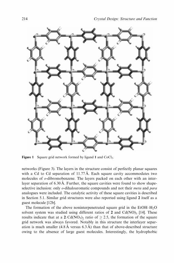
Figure 1 Square grid network formed by ligand 1 and CoCl2.
networks (Figure 3). The layers in the structure consist of perfectly planar squares
with a Cd to Cd separation of 11.77 AÊ . Each square cavity accommodates two
molecules of o-dibromobenzene. The layers packed on each other with an inter-
layer separation of 6.30AÊ . Further, the square cavities were found to show shape-
selective inclusion: only o-dihaloaromatic compounds and not their meta and para
analogues were included. The catalytic activity of these square cavities is described
in Section 5.1. Similar grid structures were also reported using ligand 2 itself as a
guest molecule [12b].
The formation of the above noninterpenetrated square grid in the EtOH±H2O
solvent system was studied using different ratios of 2 and Cd(NO)3 [14]. These
results indicate that at a 2: Cd(NO3)2 ratio of � 2:5, the formation of the square
grid network was always favored. Notably in this structure the interlayer separ-
ation is much smaller (4.8 AÊ versus 6.3 AÊ ) than that of above-described structure
owing to the absence of large guest molecules. Interestingly, the hydrophobic
214 Crystal Design: Structure and Function

Figure 2 Interpenetrated square grid network in the crystal structure of {[Zn(2)2(H2O)2][SiF6]}n.
square cavities were occupied by the hydrogen-bonded tetramers of two nitrates
and two water molecules (Figure 4). At a 2: Cd(NO3)2 ratio of � 3, the square grid
network was found to be in competition with the 1D chain, which is a 1:1 aggregate
of 2 and Cd(NO3)2, owing to the presence of excess of 2. At higher 2: Cd(NO3)2ratios it was found that the more predominant species was a bimetallic aggregate.
The square grid networks of ligand 2 and Ni(NO3)2 or Co(NO3)2 were studied
by Zaworotko and co-workers [15]. In these studies, the square grid networks
were prepared in the presence of several types of guest molecules. For example,
hydrocarbons as diverse as benzene and pyrene and also both electron-rich (naph-
thalene, anisole and veratrole) and electron-poor (nitrobenzene) guests were
included. From these studies it is understood that depending on the host±guest
stoichiometry, the interlayer separation can vary from 6 to 8 AÊ and the square
grid netw can pack on each other in three types of packing modes. Further, some
of these grid structures reveal that the guest molecules can form networks of their
own by interacting with each other via aromatic interactions. Such noncovalent
networks of guest molecules were found to interpenetrate through square grid net-
works (Figure 5) [16]. These structures provide a unique opportunity for the
Layered Materials by Design 215
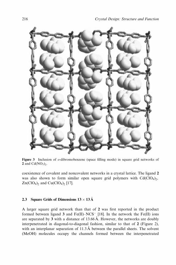
Figure 3 Inclusion of o-dibromobenzene (space ®lling mode) in square grid networks of2 and Cd(NO3)2.
coexistence of covalent and noncovalent networks in a crystal lattice. The ligand 2
was also shown to form similar open square grid polymers with Cd(ClO4)2,
Zn(ClO4)2 and Cu(ClO4)2 [17].
2.3 Square Grids of Dimensions 13� 13 ÊA
A larger square grid network than that of 2 was ®rst reported in the product
formed between ligand 3 and Fe(II)±NCSÿ [18]. In the network the Fe(II) ions
are separated by 3 with a distance of 13.66 AÊ . However, the networks are doubly
interpenetrated in diagonal-to-diagonal fashion, similar to that of 2 (Figure 2),
with an interplanar separation of 11.3AÊ between the parallel sheets. The solvent
(MeOH) molecules occupy the channels formed between the interpenetrated
216 Crystal Design: Structure and Function

Figure 4 Inclusion of nitrates and water molecules in the square grid networks of 2 andCd(NO3)2.
layers. This structure was found to show an interesting property of spin crossover
that will be discussed in the Section 5.2. Similar types of interpenetrated networks
were also observed between 3 and Ni(NO3)2=Co(NO3)2 [15] and also between 4
and Co(SCN)2 [19]. The relatively new ligand 4,40-azobipyridine, 5, was also
shown to act as ligand 3 to form interpenetrated and noninterpenetrated square
grid architectures with Co(NCS)2 or ZnSiF6 and Cd(NO3)2, respectively [20].
2.4 Square Grids of Dimensions 15� 15 ÊA
The ligand 7 with Ni(NO3)2 in the presence of benzene and MeOH was shown to
form a coordination polymer {[Ni(7)2(H2O)2] � benzene � 5(MeOH) �2 (NO3)}n [21].
The crystal structure of this complex exhibited open square grid cavities with
Layered Materials by Design 217
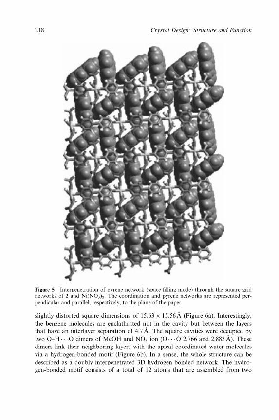
Figure 5 Interpenetration of pyrene network (space ®lling mode) through the square gridnetworks of 2 and Ni(NO3)2. The coordination and pyrene networks are represented per-pendicular and parallel, respectively, to the plane of the paper.
slightly distorted square dimensions of 15:63� 15:56 ÊA (Figure 6a). Interestingly,
the benzene molecules are enclathrated not in the cavity but between the layers
that have an interlayer separation of 4.7 AÊ . The square cavities were occupied by
two O±H � � �O dimers of MeOH and NO3 ion (O � � �O 2.766 and 2.883 AÊ ). These
dimers link their neighboring layers with the apical coordinated water molecules
via a hydrogen-bonded motif (Figure 6b). In a sense, the whole structure can be
described as a doubly interpenetrated 3D hydrogen bonded network. The hydro-
gen-bonded motif consists of a total of 12 atoms that are assembled from two
218 Crystal Design: Structure and Function
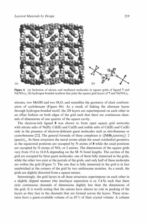
(a) (b)
Figure 6 (a) Inclusion of nitrate and methanol molecules in square grids of ligand 7 andNi(NO3)2; (b) hydrogen-bonded synthon that joins the square grid layers of 7 and Ni(NO3)2.
nitrates, two MeOH and two H2O, and resembles the geometry of chair conform-
ation of cyclohexane (Figure 6b). As a result of linking the alternate layers
through hydrogen-bonded motif, the 2D layers are superimposed on each other in
an offset fashion on both edges of the grid such that there are continuous chan-
nels of dimensions of one quarter of the square cavity.
The electron-rich ligand 8 was shown to form open square grid networks
with nitrate salts of Ni(II), Cd(II) and Cu(II) and iodide salts of Cd(II) and Co(II)
only in the presence of electron-de®cient guest molecules such as nitrobenzene or
cyanobenzene [22]. The general formula of these complexes is {[M(8)2(anion)2] � 2(guest)}n. In these structures the metal atoms adopt the usual octahedral geometry
as the equatorial positions are occupied by N atoms of 8 while the axial positions
are occupied by O atoms of NO3 or I anions. The dimensions of the square grids
vary from 15.6 to 16.0 AÊ depending on the M±N bond lengths. The cavities of the
grid are occupied by three guest molecules: one of them fully immersed in the grids,
while the other two exist at the portals of the grids, and only half of these molecules
are within the grid (Figure 7). The one that is fully immersed in the grid is in fact
sandwiched at the corners of the grid by two anthracene moieties. As a result, the
grids are slightly distorted from a square nature.
Interestingly, the grid layers in all these structures superimpose on each other in
a slightly slipped manner (the interlayer separation is ca 5.4AÊ ) such that there
exist continuous channels of dimensions slightly less than the dimensions of
the grid. It is worth noting that the anions have almost no role in packing of the
layers as they face in the channels that are formed across the layers. These struc-
tures have a guest-available volume of ca 45 % of their crystal volume. A column
Layered Materials by Design 219
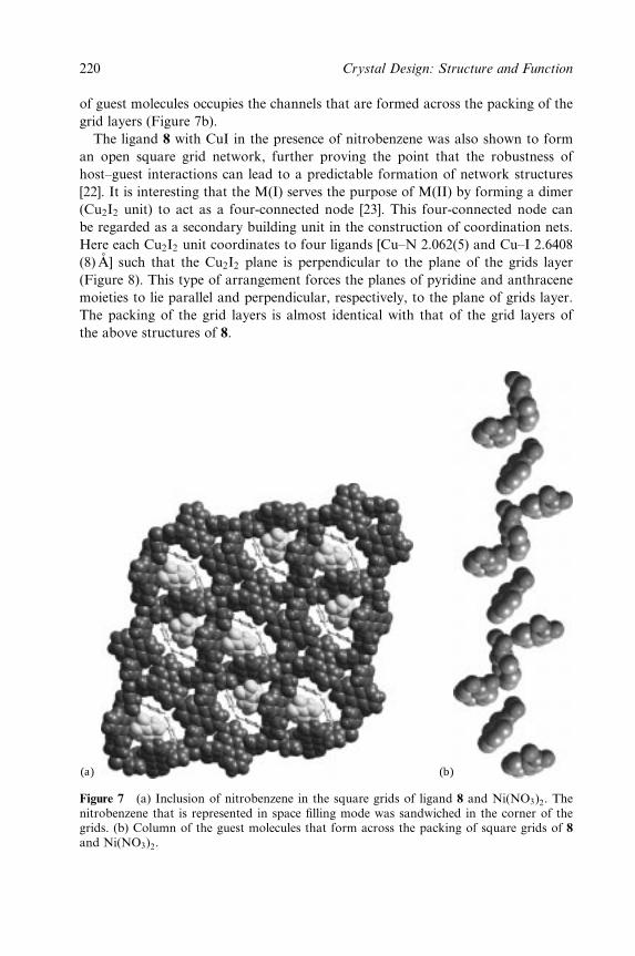
of guest molecules occupies the channels that are formed across the packing of the
grid layers (Figure 7b).
The ligand 8 with CuI in the presence of nitrobenzene was also shown to form
an open square grid network, further proving the point that the robustness of
host±guest interactions can lead to a predictable formation of network structures
[22]. It is interesting that the M(I) serves the purpose of M(II) by forming a dimer
(Cu2I2 unit) to act as a four-connected node [23]. This four-connected node can
be regarded as a secondary building unit in the construction of coordination nets.
Here each Cu2I2 unit coordinates to four ligands [Cu±N 2.062(5) and Cu±I 2.6408
(8) AÊ ] such that the Cu2I2 plane is perpendicular to the plane of the grids layer
(Figure 8). This type of arrangement forces the planes of pyridine and anthracene
moieties to lie parallel and perpendicular, respectively, to the plane of grids layer.
The packing of the grid layers is almost identical with that of the grid layers of
the above structures of 8.
(a) (b)
Figure 7 (a) Inclusion of nitrobenzene in the square grids of ligand 8 and Ni(NO3)2. Thenitrobenzene that is represented in space ®lling mode was sandwiched in the corner of thegrids. (b) Column of the guest molecules that form across the packing of square grids of 8and Ni(NO3)2.
220 Crystal Design: Structure and Function
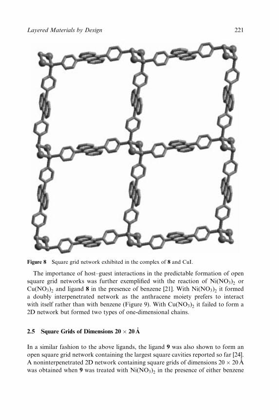
Figure 8 Square grid network exhibited in the complex of 8 and CuI.
The importance of host±guest interactions in the predictable formation of open
square grid networks was further exempli®ed with the reaction of Ni(NO3)2 or
Cu(NO3)2 and ligand 8 in the presence of benzene [21]. With Ni(NO3)2 it formed
a doubly interpenetrated network as the anthracene moiety prefers to interact
with itself rather than with benzene (Figure 9). With Cu(NO3)2 it failed to form a
2D network but formed two types of one-dimensional chains.
2.5 Square Grids of Dimensions 20� 20 ÊA
In a similar fashion to the above ligands, the ligand 9 was also shown to form an
open square grid network containing the largest square cavities reported so far [24].
A noninterpenetrated 2D network containing square grids of dimensions 20� 20 ÊA
was obtained when 9 was treated with Ni(NO3)2 in the presence of either benzene
Layered Materials by Design 221
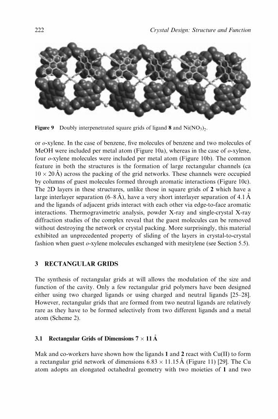
Figure 9 Doubly interpenetrated square grids of ligand 8 and Ni(NO3)2.
or o-xylene. In the case of benzene, ®ve molecules of benzene and two molecules of
MeOH were included per metal atom (Figure 10a), whereas in the case of o-xylene,
four o-xylene molecules were included per metal atom (Figure 10b). The common
feature in both the structures is the formation of large rectangular channels (ca
10� 20 ÊA) across the packing of the grid networks. These channels were occupied
by columns of guest molecules formed through aromatic interactions (Figure 10c).
The 2D layers in these structures, unlike those in square grids of 2 which have a
large interlayer separation (6±8AÊ ), have a very short interlayer separation of 4.1 AÊ
and the ligands of adjacent grids interact with each other via edge-to-face aromatic
interactions. Thermogravimetric analysis, powder X-ray and single-crystal X-ray
diffraction studies of the complex reveal that the guest molecules can be removed
without destroying the network or crystal packing. More surprisingly, this material
exhibited an unprecedented property of sliding of the layers in crystal-to-crystal
fashion when guest o-xylene molecules exchanged with mesitylene (see Section 5.5).
3 RECTANGULAR GRIDS
The synthesis of rectangular grids at will allows the modulation of the size and
function of the cavity. Only a few rectangular grid polymers have been designed
either using two charged ligands or using charged and neutral ligands [25±28].
However, rectangular grids that are formed from two neutral ligands are relatively
rare as they have to be formed selectively from two different ligands and a metal
atom (Scheme 2).
3.1 Rectangular Grids of Dimensions 7� 11 ÊA
Mak and co-workers have shown how the ligands 1 and 2 react with Cu(II) to form
a rectangular grid network of dimensions 6:83� 11:15 ÊA (Figure 11) [29]. The Cu
atom adopts an elongated octahedral geometry with two moieties of 1 and two
222 Crystal Design: Structure and Function

(a)
(b) (c)
Figure 10 Inclusion of (a) benzene and MeOH and (b) o-xylene in the 20� 20 ÊA squaregrids of 9 and Ni(NO3)2; (c) column of o-xylene molecules observed in the crystal structureof {[Ni(9)2(NO3)2] � 4(o-xylene)}n.
moieties of 2 at the equatorial positions and two water molecules at the axial
positions. The offset superposition of each pair of adjacent layers by half of the
longer edges resulted in smaller rectangular channels (ca 5:6� 6:8 ÊA) that are
occupied by PF6ÿ ions.
Layered Materials by Design 223
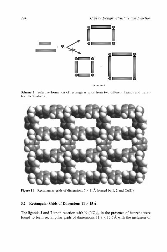
+
+
Scheme 2
Scheme 2 Selective formation of rectangular grids from two different ligands and transi-tion metal atoms.
Figure 11 Rectangular grids of dimensions 7� 11 ÊA formed by 1, 2 and Cu(II).
3.2 Rectangular Grids of Dimensions 11� 15 ÊA
The ligands 2 and 7 upon reaction with Ni(NO3)2 in the presence of benzene were
found to form rectangular grids of dimensions 11:3� 15:6 ÊA with the inclusion of
224 Crystal Design: Structure and Function
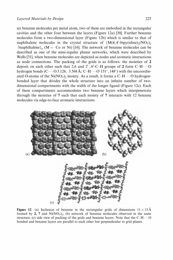
six benzene molecules per metal atom, two of them are embodied in the rectangular
cavities and the other four between the layers (Figure 12a) [30]. Further benzene
molecules form a two-dimensional layer (Figure 12b) which is similar to that of
naphthalene molecules in the crystal structure of {M(4, 40-bipyridine)2(NO3)2�3naphthalene}n (M � Co or Ni) [16]. The network of benzene molecules can be
described as one of the semi-regular planar networks, which were described by
Wells [31], when benzene molecules are depicted as nodes and aromatic interactions
as node connections. The packing of the grids is as follows: the moieties of 2
deposit on each other such that 2,6 and 20 , 60-C±H groups of 2 form C±H � � �Ohydrogen bonds (C � � �O3:126, 3:568 ÊA; C±H � � �O 151�, 148�) with the uncoordin-
ated O-atoms of the Ni(NO3)2 moiety. As a result, it forms a C±H � � �O hydrogen-
bonded layer that divides the whole structure into an in®nite number of two-
dimensional compartments with the width of the longer ligand (Figure 12c). Each
of these compartments accommodates two benzene layers which interpenetrate
through the moieties of 7 such that each moiety of 7 interacts with 12 benzene
molecules via edge-to-face aromatic interactions.
(a)
(c)
(b)
Figure 12 (a) Inclusion of benzene in the rectangular grids of dimensions 11� 15 ÊAformed by 2, 7 and Ni(NO3)2; (b) network of benzene molecules observed in the samestructure; (c) side view of packing of the grids and benzene layers. Note that the C±H � � �Obonded and benzene layers are parallel to each other but perpendicular to grid planes.
Layered Materials by Design 225
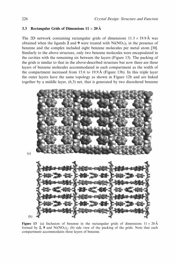
3.3 Rectangular Grids of Dimensions 11� 20 ÊA
The 2D network containing rectangular grids of dimensions 11:3� 19:9 ÊA was
obtained when the ligands 2 and 9 were treated with Ni(NO3)2 in the presence of
benzene and the complex included eight benzene molecules per metal atom [30].
Similarly to the above structure, only two benzene molecules were encapsulated in
the cavities with the remaining six between the layers (Figure 13). The packing of
the grids is similar to that in the above-described structure but now there are three
layers of benzene molecules accommodated in each compartment as the width of
the compartment increased from 15.6 to 19.9 ÊA (Figure 13b). In this triple layer
the outer layers have the same topology as shown in Figure 12b and are linked
together by a middle layer, (6,3) net, that is generated by two disordered benzene
(a)
(b)
Figure 13 (a) Inclusion of benzene in the rectangular grids of dimensions 11� 20 ÊAformed by 2, 9 and Ni(NO3)2; (b) side view of the packing of the grids. Note that eachcompartment accommodates three layers of benzene.
226 Crystal Design: Structure and Function
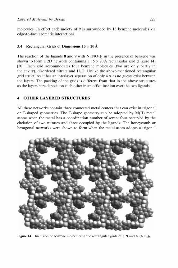
molecules. In effect each moiety of 9 is surrounded by 18 benzene molecules via
edge-to-face aromatic interactions.
3.4 Rectangular Grids of Dimensions 15� 20 ÊA
The reaction of the ligands 8 and 9 with Ni(NO3)2 in the presence of benzene was
shown to form a 2D network containing a 15� 20 ÊA rectangular grid (Figure 14)
[30]. Each grid accommodates four benzene molecules (two are only partly in
the cavity), disordered nitrate and H2O. Unlike the above-mentioned rectangular
grid structures it has an interlayer separation of only 4 AÊ as no guests exist between
the layers. The packing of the grids is different from that in the above structures
as the layers here deposit on each other in an offset fashion over the two ligands.
4 OTHER LAYERED STRUCTURES
All these networks contain three connected metal centers that can exist in trigonal
or T-shaped geometries. The T-shape geometry can be adopted by M(II) metal
atoms when the metal has a coordination number of seven: four occupied by the
chelation of two nitrates and three occupied by the ligands. The honeycomb or
hexagonal networks were shown to form when the metal atom adopts a trigonal
Figure 14 Inclusion of benzene molecules in the rectangular grids of 8, 9 and Ni(NO3)2.
Layered Materials by Design 227
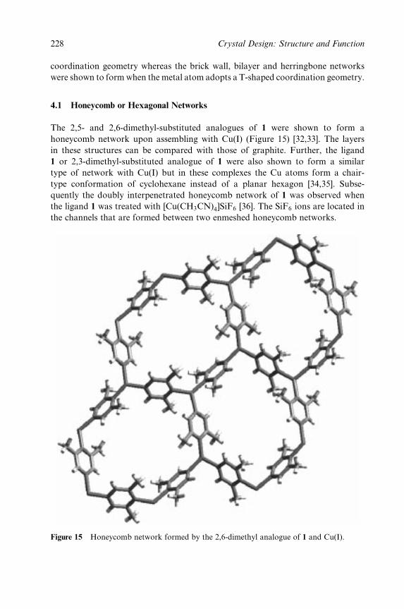
coordination geometry whereas the brick wall, bilayer and herringbone networks
were shown to form when the metal atom adopts a T-shaped coordination geometry.
4.1 Honeycomb or Hexagonal Networks
The 2,5- and 2,6-dimethyl-substituted analogues of 1 were shown to form a
honeycomb network upon assembling with Cu(I) (Figure 15) [32,33]. The layers
in these structures can be compared with those of graphite. Further, the ligand
1 or 2,3-dimethyl-substituted analogue of 1 were also shown to form a similar
type of network with Cu(I) but in these complexes the Cu atoms form a chair-
type conformation of cyclohexane instead of a planar hexagon [34,35]. Subse-
quently the doubly interpenetrated honeycomb network of 1 was observed when
the ligand 1 was treated with [Cu(CH3CN)4]SiF6 [36]. The SiF6 ions are located in
the channels that are formed between two enmeshed honeycomb networks.
Figure 15 Honeycomb network formed by the 2,6-dimethyl analogue of 1 and Cu(I).
228 Crystal Design: Structure and Function
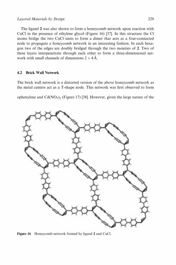
The ligand 2 was also shown to form a honeycomb network upon reaction with
CuCl in the presence of ethylene glycol (Figure 16) [37]. In this structure the Cl
atoms bridge the two CuCl units to form a dimer that acts as a four-connected
node to propagate a honeycomb network in an interesting fashion. In each hexa-
gon two of the edges are doubly bridged through the two moieties of 2. Two of
these layers interpenetrate through each other to form a three-dimensional net-
work with small channels of dimensions 2� 4 ÊA.
4.2 Brick Wall Network
The brick wall network is a distorted version of the above honeycomb network as
the metal centers act as a T-shape node. This network was ®rst observed to form
between a more ¯exible ligand such as 1,4-bis[(4-pyridyl)methyl]-2,3,5,6-tetra¯uor-
ophenylene and Cd(NO3)2 (Figure 17) [38]. However, given the large nature of the
Figure 16 Honeycomb network formed by ligand 2 and CuCl. AQ1
Layered Materials by Design 229
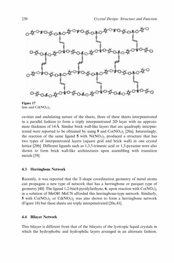
Figure 17 Brick wall network formed by 1,4-bis[(4-pyridyl)methyl]-2,3,5,6-tetra¯uropheny-lene and Cd(NO3)2.
cavities and undulating nature of the sheets, three of these sheets interpenetrated
in a parallel fashion to form a triply interpenetrated 2D layer with an approxi-
mate thickness of 14 AÊ . Similar brick wall-like layers that are quadruply interpne-
trated were reported to be obtained by using 5 and Co(NO3)2 [20a]. Interestingly,
the reaction of the same ligand 5 with Ni(NO3)2 produced a structure that has
two types of interpenetrated layers (square grid and brick wall) in one crystal
lattice [20b]. Different ligands such as 1,3,5-trimesic acid or 1,3-pyrazine were also
shown to form brick wall-like architectures upon assembling with transition
metals [39].
4.3 Herringbone Network
Recently, it was reported that the T-shape coordination geometry of metal atoms
can propagate a new type of network that has a herringbone or parquet type of
geometry [40]. The ligand 1,2-bis(4-pyridyl)ethyne, 6, upon reaction with Co(NO3)2in a solution of MeOH±MeCN afforded this herringbone-type network. Similarly,
5 with Co(NO3)2 or Cd(NO3)2 was also shown to form a herringbone network
(Figure 18) but these sheets are triply interpenetrated [20a,41].
4.4 Bilayer Network
This bilayer is different from that of the bilayers of the lyotropic liquid crystals in
which the hydrophobic and hydrophilic layers arranged in an alternate fashion.
230 Crystal Design: Structure and Function
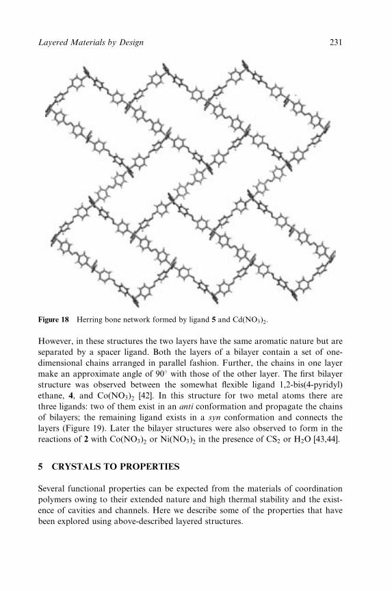
Figure 18 Herring bone network formed by ligand 5 and Cd(NO3)2.
However, in these structures the two layers have the same aromatic nature but are
separated by a spacer ligand. Both the layers of a bilayer contain a set of one-
dimensional chains arranged in parallel fashion. Further, the chains in one layer
make an approximate angle of 908 with those of the other layer. The ®rst bilayer
structure was observed between the somewhat ¯exible ligand 1,2-bis(4-pyridyl)
ethane, 4, and Co(NO3)2 [42]. In this structure for two metal atoms there are
three ligands: two of them exist in an anti conformation and propagate the chains
of bilayers; the remaining ligand exists in a syn conformation and connects the
layers (Figure 19). Later the bilayer structures were also observed to form in the
reactions of 2 with Co(NO3)2 or Ni(NO3)2 in the presence of CS2 or H2O [43,44].
5 CRYSTALS TO PROPERTIES
Several functional properties can be expected from the materials of coordination
polymers owing to their extended nature and high thermal stability and the exist-
ence of cavities and channels. Here we describe some of the properties that have
been explored using above-described layered structures.
Layered Materials by Design 231
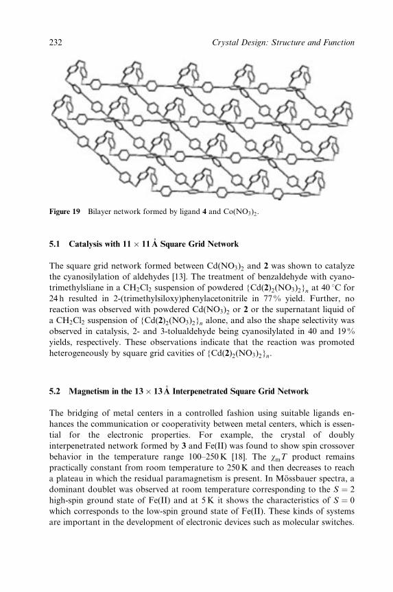
Figure 19 Bilayer network formed by ligand 4 and Co(NO3)2.
5.1 Catalysis with 11� 11 ÊA Square Grid Network
The square grid network formed between Cd(NO3)2 and 2 was shown to catalyze
the cyanosilylation of aldehydes [13]. The treatment of benzaldehyde with cyano-
trimethylsliane in a CH2Cl2 suspension of powdered {Cd(2)2(NO3)2}n at 40 8C for
24 h resulted in 2-(trimethylsiloxy)phenylacetonitrile in 77 % yield. Further, no
reaction was observed with powdered Cd(NO3)2 or 2 or the supernatant liquid of
a CH2Cl2 suspension of {Cd(2)2(NO3)2}n alone, and also the shape selectivity was
observed in catalysis, 2- and 3-tolualdehyde being cyanosilylated in 40 and 19 %
yields, respectively. These observations indicate that the reaction was promoted
heterogeneously by square grid cavities of {Cd(2)2(NO3)2}n.
5.2 Magnetism in the 13� 13 ÊA Interpenetrated Square Grid Network
The bridging of metal centers in a controlled fashion using suitable ligands en-
hances the communication or cooperativity between metal centers, which is essen-
tial for the electronic properties. For example, the crystal of doubly
interpenetrated network formed by 3 and Fe(II) was found to show spin crossover
behavior in the temperature range 100±250K [18]. The wmT product remains
practically constant from room temperature to 250K and then decreases to reach
a plateau in which the residual paramagnetism is present. In MoÈssbauer spectra, a
dominant doublet was observed at room temperature corresponding to the S � 2
high-spin ground state of Fe(II) and at 5K it shows the characteristics of S � 0
which corresponds to the low-spin ground state of Fe(II). These kinds of systems
are important in the development of electronic devices such as molecular switches.
232 Crystal Design: Structure and Function
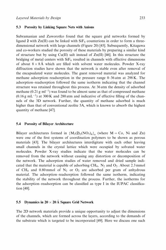
5.3 Porosity by Linking Square Nets with Anions
Subramanian and Zaworotko found that the square grid networks formed by
ligand 2 with Zn(II) can be linked with SiF6 counterions in order to form a three-
dimensional network with large channels (Figure 20) [45]. Subsequently, Kitagawa
and co-workers studied the porosity of these materials by preparing a similar kind
of structure but by using Cu(II) salt instead of Zn(II) [46]. In this structure the
bridging of metal centers with SiF6 resulted in channels with effective dimensions
of about 8� 8 ÊA which are ®lled with solvent water molecules. Powder X-ray
diffraction studies have shown that the network is stable even after removal of
the encapsulated water molecules. The guest removed material was analyzed for
methane adsorption±readsorption in the pressure range 0±36 atm at 298K. The
adsorption±readsorption followed the same isotherm indicating that the channel
structure was retained throughout this process. At 36 atm the density of adsorbed
methane (0:21 g mlÿ1) was found to be almost same as that of compressed methane
(0:16 g mLÿ1) at 300K and 280 atm and indicative of effective ®lling of the chan-
nels of the 3D network. Further, the quantity of methane adsorbed is much
higher than that of conventional zeolite 5A, which is known to absorb the highest
quantity of methane [47].
5.4 Porosity of Bilayer Architecture
Bilayer architectures formed in {M2(2)3(NO3)4}n (where M � Co, Ni and Zn)
were one of the ®rst systems of coordination polymers to be shown as porous
materials [43]. The bilayer architectures interdigitate with each other leaving
small channels in the crystal lattice which were occupied by solvated water
molecules. Powder X-ray studies indicate that the water molecules can be
removed from the network without causing any distortion or decomposition of
the network. The adsorption studies of water removed and dried sample indi-
cated that the material is capable of adsorbing CH4, N2 and O2. About 2.3 mmol
of CH4 and 0.80mmol of N2 or O2 are adsorbed per gram of anhydrous
material. The adsorption±readsorption followed the same isotherm, indicating
the stability of the network throughout the process. Further, the isotherms for
the adsorption±readsorption can be classi®ed as type I in the IUPAC classi®ca-
tion [48].
5.5 Dynamics in 20� 20 ÊA Square Grid Network
The 2D network materials provide a unique opportunity to adjust the dimensions
of the channels, which are formed across the layers, according to the demands of
the substrate which is targeted to be incorporated [49]. Here we discuss one such
Layered Materials by Design 233
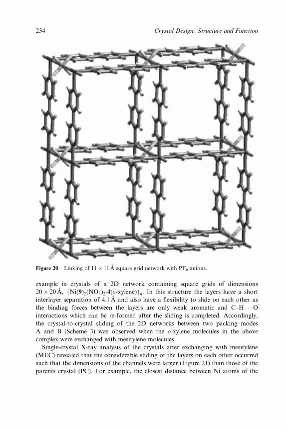
Figure 20 Linking of 11� 11 ÊA square grid network with PF6 anions.
example in crystals of a 2D network containing square grids of dimensions
20� 20 ÊA, {Ni(9)2(NO3)2�4(o-xylene)}n. In this structure the layers have a short
interlayer separation of 4.1AÊ and also have a ¯exibility to slide on each other as
the binding forces between the layers are only weak aromatic and C±H � � �Ointeractions which can be re-formed after the sliding is completed. Accordingly,
the crystal-to-crystal sliding of the 2D networks between two packing modes
A and B (Scheme 3) was observed when the o-xylene molecules in the above
complex were exchanged with mesitylene molecules.
Single-crystal X-ray analysis of the crystals after exchanging with mesitylene
(MEC) revealed that the considerable sliding of the layers on each other occurred
such that the dimensions of the channels were larger (Figure 21) than those of the
parents crystal (PC). For example, the closest distance between Ni atoms of the
234 Crystal Design: Structure and Function
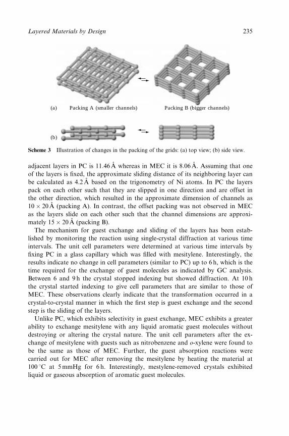
(a)
(b)
Packing A (smaller channels) Packing B (bigger channels)
Scheme 3 Illustration of changes in the packing of the grids: (a) top view; (b) side view.
adjacent layers in PC is 11:46 ÊA whereas in MEC it is 8:06 ÊA. Assuming that one
of the layers is ®xed, the approximate sliding distance of its neighboring layer can
be calculated as 4.2 AÊ based on the trigonometry of Ni atoms. In PC the layers
pack on each other such that they are slipped in one direction and are offset in
the other direction, which resulted in the approximate dimension of channels as
10� 20 ÊA (packing A). In contrast, the offset packing was not observed in MEC
as the layers slide on each other such that the channel dimensions are approxi-
mately 15� 20 ÊA (packing B).
The mechanism for guest exchange and sliding of the layers has been estab-
lished by monitoring the reaction using single-crystal diffraction at various time
intervals. The unit cell parameters were determined at various time intervals by
®xing PC in a glass capillary which was ®lled with mesitylene. Interestingly, the
results indicate no change in cell parameters (similar to PC) up to 6 h, which is the
time required for the exchange of guest molecules as indicated by GC analysis.
Between 6 and 9 h the crystal stopped indexing but showed diffraction. At 10 h
the crystal started indexing to give cell parameters that are similar to those of
MEC. These observations clearly indicate that the transformation occurred in a
crystal-to-crystal manner in which the ®rst step is guest exchange and the second
step is the sliding of the layers.
Unlike PC, which exhibits selectivity in guest exchange, MEC exhibits a greater
ability to exchange mesitylene with any liquid aromatic guest molecules without
destroying or altering the crystal nature. The unit cell parameters after the ex-
change of mesitylene with guests such as nitrobenzene and o-xylene were found to
be the same as those of MEC. Further, the guest absorption reactions were
carried out for MEC after removing the mesitylene by heating the material at
100 8C at 5mmHg for 6 h. Interestingly, mestylene-removed crystals exhibited
liquid or gaseous absorption of aromatic guest molecules.
Layered Materials by Design 235
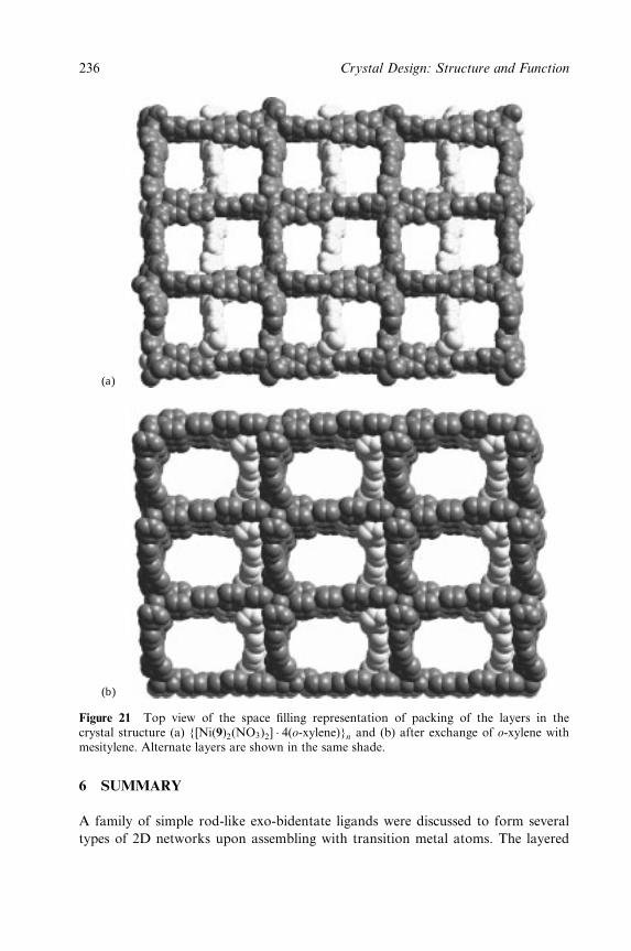
(a)
(b)
Figure 21 Top view of the space ®lling representation of packing of the layers in thecrystal structure (a) {[Ni(9)2(NO3)2] � 4(o-xylene)}n and (b) after exchange of o-xylene withmesitylene. Alternate layers are shown in the same shade.
6 SUMMARY
A family of simple rod-like exo-bidentate ligands were discussed to form several
types of 2D networks upon assembling with transition metal atoms. The layered
236 Crystal Design: Structure and Function
networks containing square and rectangular grid cavities exempli®ed the import-
ance of a modular approach in ®ne tuning the shape and size of the cavities. The
T-shaped nodes exhibited three types of layered structures so far: (1) brick wall;
(2) bilayer; and (3) herringbone. The exhibition of a variety of networks by the
same structural unit has been described as supramolecular isomerism by Zawor-
otko and co-workers. Concerning the porosity, the emphasis so far has been on
designing coordination networks that are stable for reversible adsorption and
readsorption of guest molecules without undergoing phase or morphology
changes. Accordingly, in recent reports several coordination network materials
were shown to exhibit such porous properties. However, the example presented in
Section 5.5 comes under a new class of compound in which the solid responds to
the demands of the external stimuli, exchange of guest molecules in this particular
case. Such solids were termed third-generation solids by Kitagawa and Kondo [3c]
and may appear frequently in the future.
REFERENCES
1. (a) G. M. J. Schmidt, Pure Appl. Chem., 27, 647 (1971); (b) G. R. Desiraju, Crystal
Engineering: the Design of Organic Solids, Materials Science Monographs 54, Elsevier,Amsterdam (1989).
2. (a) G. R. Desiraju, Angew. Chem., Int. Ed. Engl., 34, 2311 (1995); (b) Y. Aoyama,Topp. Curr. Chem., 198, 131 (1998); (c) M. J. Zaworotko, Chem. Commun., 1 (2001).
3. (a) R. Robson, J. Chem. Soc., Dalton Trans., 3735 (2000); (b) D. Braga, J. Chem.
Soc., Dalton Trans., 3705 (2000); (b) O. M. Yaghi, H. Li, C. Davis, D. Richardsonand T. L. Groy, Acc. Chem. Res., 31, 474 (1998); (c) S. Kitagawa and M. Kondo,Bull. Chem. Soc. Jpn., 71, 1739 (1998); d) D.-L. Long, A. J. Blake, N. R. Champness,C. Wilson and M. SchroÈder, Angew. Chem., 113, 2510 (2001); (e) S. A. Bourne, J. Lu,A. Mondal, B. Moulton and M. J. Zaworotko, Angew. Chem., 113, 2169 (2001); (f)H. Li, M. Eddaoudi, M. O'Keeffe and O. M. Yaghi, Nature, 402, 276 (1999); (g)J. S. Seo, D. Whang, H. Lee, S. I. Jun, J. Oh, Y. J. Jeon and K. Kim, Nature, 404, 982(2000).
4. (a) M. Eddaoudi, J. Kim, N. Rosi, D. Vodak, J. Wachter, M. O'Keeffe and O.M. Yaghi, Science, 295, 469 (2002); (b) J.-S. Seo, D. Whang, H. Lee, S. I. Jun, J. Oh,Y. J. Jeon and K. Kim, Nature, 404, 982 (2000); (c) R. Kitaura, K. Fujimoto, S.-I.Noro, M. Kondo and S. Kitagawa, Angew. Chem., Int. Ed. Engl., 41, 133 (2002); (d) K.S. Min, M. P. Suh, J. Am. Chem. Soc., 122, 6834 (2000).
5. (a) S. R. Batten and R. Robson, Angew. Chem., Int. Ed. Engl., 37, 1460 (1998); (b)S. R. Batten, Cryst. Eng. Commun., 18, 1 (2001).
6. (a) P. W. Carreck, M. Goldstein, E. M. McPartlin and W. D. Unsworth, J. Chem. Soc.
D, 1634 (1971); (b) C. Gairing, A. Lentz, E. Grosse, M. Haseidl and L. Walz,Z. Kristallogr., 211, 804 (1996).
7. J. Darriet, M. S. Haddad, E. N. Duesler and D. N. Hendrickson, Inorg. Chem., 18,2679 (1979).
8. J. S. Haynes, S. J. Rettig, J. R. Sams, R. C. Thompson and J. Trotter, Can. J. Chem.,65, 420 (1987).
9. J. A. Real, G. De Munno, M. C. Munoz and M. Julve, Inorg. Chem., 30, 2701 (1991).10. T. Oteino, S. J. Rettig, R. C. Thompson and J. Trotter, Inorg. Chem., 32, 1607 (1993).
Layered Materials by Design 237
11. J. Lu, T. Paliwala, S. C. Lim, C. Yu, T. Niu and A. J. Jacobson, Inorg. Chem., 36, 923(1997).
12. (a) R. W. Gable, B. F. Hoskins, and R. Robson, J. Chem. Soc., Chem. Commun., 1677(1990); (b) R. Robson, B. F. Abrahams, S. R. Batten, R. W. Gable, B. F. Hoskins andJ. Liu, in Supramolecular Architecture, ed. T. Bein, ACS Symposium Series, Vol. 499,American Chemical Society, Washington, DC, chapt. 19 (1992).
13. M. Fujita, Y. J. Kwon, S. Washizu and K. Ogura, J. Am. Chem. Soc., 116, 1151 (1994).14. M. Aoyagi, K. Biradha and M. Fujita, Bull. Chem. Soc. Jpn., 1369 (2000).15. K. Biradha, D. Dennis, V. A. MacKinnon, C. Seward and M. J. Zaworotko, in Current
Challenges on Large Supramolecular Assemblies, ed. G. Tsoucaris, Kluwer, Dordrecht,pp. 115±132 (1999).
16. a) K. Biradha, K. V. Domasevitch, B. Moulton, C. Seward and M. J. Zaworotko,Chem. Commun., 1327 (1999); (b) K. Biradha, K. V. Domasasevitch, C. Hogg,B. Moulton, K. N. Power and M. J. Zaworotko, Cryst. Eng., 2, 37 (1999).
17. M.-L. Tong, B.-H. Ye, J.-W. Cai, X.-M. Chen, and S. W. Ng, Inorg. Chem., 37, 2645(1998).
18. J. A. Real, E. AndreÂs, M. C. MunÄoz, M. Julve, T. Granier, A. Bousseksou andF. Varret, Science, 268, 265 (1995).
19. S. H. Park, K. M. Kim, S.-G. Lee and O.-S. Jung, Bull. Korean Chem. Soc., 19, 79(1998).
20. (a) M. Kondo, M. Shimamura, S.-I. Noro, S. Minakoshi, A. Asami, K. Seki andS. Kitagawa, Chem. Mater., 12, 1288 (2000); (b) L. Carlucci, G. Ciani and D. M. Pro-serpio, New J. Chem., 1319 (1998).
21. K. Biradha and M. Fujita, J. Chem. Soc., Dalton. Trans., 3805 (2000).22. K. Biradha and M. Fujita, J. Inclus. Phenom., 41, 201±208 (2001).23. K. Biradha, M. Aoyagi and M. Fujita, J. Am. Chem. Soc., 122, 2397 (2000).24. K. Biradha, Y. Hongo and M. Fujita, Angew. Chem., Int. Ed. Engl., 39, 3843 (2000)25. S. Kawata, S. Kitagawa, M. Konda, I. Furuchi and M. Munakata, Angew. Chem., Int.
Ed. Engl., 33, 1665 (1994).26. L. R. MacGillivray, R. H. Groeneman and J. L. Atwood, J. Am. Chem. Soc., 120, 2677
(1998).27. R. H. Groeneman, L. R. MacGillivray and J. L. Atwood, Chem. Commun., 2735
(1998).28. L.-M. Zheng, X. Fang, K.-H. Lii, H.-H. Song, X.-Q. Xin, H.-K. Fun, K. Chinnakali
and I. A. Razak, J. Chem. Soc., Dalton Trans., 2311 (1999).29. M.-L. Tong, X.-M. Chen, X.-L. Yu and T. C. W. Mak, J. Chem. Soc., Dalton Trans., 5
(1998).30. K. Biradha and M. Fujita, Chem. Commun. 15 (2001).31. A. F. Wells, Structural Inorganic Chemistry, 5th edn, Clarendon Press, Oxford p. 82
[also see p. 613 (MxO3), p. 1006 (-quartz), p. 1302 (CaCu5)].32. T. Otieno, S. J. Rettig, R. C. Thompson, and J. Trotter, Inorg. Chem., 32, 1607 (1993).33. S. Kitagawa, S. Kawata, M. Kondo, Y. Nozaka and M. Munakata, Bull. Chem. Soc.
Jpn., 66, 3387, (1993).34. S. Kitagawa, M. Munakata and T. Tanimura, Inorg. Chem., 31, 1714 (1992).35. M. M. Turnbull, G. Pon and R. D. Willett, Polyhedron, 10, 1835 (1991).36. L. R. MacGillivray, S. Subramanian and M. J. Zaworotko, J. Chem. Soc., Chem.
Commun., 1325 (1994).37. O. M. Yaghi and G. Li, Angew. Chem., Int. Ed. Engl., 34, 207 (1995).38. M. Fujita, Y. J. Kwon, O. Sasaki, K. Yamaguchi and K. Ogura, J. Am. Chem. Soc.,
117, 7287 (1995).
AQ2
AQ3
238 Crystal Design: Structure and Function
39. (a) H. J. Choi and M. P. Suh, J. Am. Chem. Soc., 120, 10622 (1998); (b) C. V. K.Sharma and R. D. Rogers, Cryst. Eng., 1, 19 (1998).
40. Y.-B. Dong, R. C. Layland, N. G. Pschirer, M. D. Smith, U. H. F. Bunz and, H.-C. zurLoye, Chem. Mater., 11, 1413 (1999).
41. M. A. Withersby, A. J. Blake, N. R. Champness, P. A. Cooke, P. Hubberstey andM. SchroÈder, New J. Chem., 23, 573 (1999).
42. (a) T. L. Hennigar, D. C. MacQuarrie, P. Losier, R. D. Rogers and M. J. Zaworotko,Angew. Chem., Int. Ed. Engl., 36, 972 (1997); (b) R. Atencio, K. Biradha, T. L. Henni-gar, K. M. Poirier, K. N. Power, C. M. Seward, N. S. White and M. J. Zaworotko,Cryst. Eng., 1, 203 (1998).
43. M. Kondo, T. Yoshitomi, K. Seki, H. Matsuzaka and S. Kitagawa, Angew. Chem., Int.
Ed. Engl., 36, 1725 (1997).44. K. N. Power, T. L. Hennigar and M. J. Zaworotko, New J. Chem. 22, 177 (1998)45. S. Subramanian and M. J. Zaworotko, Angew. Chem., Int. Ed. Engl., 34, 2127 (1995).46. S.-I. Noro, S. Kitagawa, M. Kondo and K. Seki, Angew. Chem., Int. Ed. Engl., 39,
2082 (2000).47. (a) S.-Y. Zhang, O. Talu, D. T. Hayhurst, J. Phys. Chem. 95, 1722 (1991); (b) J. L.
Zuech, A. L. Hines, E. D. Solan, Ind. Eng. Chem. Process Des. Dev., 22, 172 (1983); (c)L. Mentasty, A. M. Woestyn and G. Zgrablich, Adsorpt. Sci. Technol., 11, 123 (1994).
48. IUPAC, Pure Appl. Chem., 57, 603 (1985).49. K. Biradha, Y. Hongo and M. Fujita, Angew. Chem., Int. Ed., 41, 3395 (2002). AQ4
Layered Materials by Design 239
Chapter 6
The Construction of One-,Two- and Three-DimensionalOrganic±Inorganic HybridMaterials from MolecularBuilding Blocks
ROBERT C. FINN, ERIC BURKHOLDER, AND JON ZUBIETA
Syracuse University, Syracuse, NY, USA
1 INTRODUCTION
The contemporary interest in inorganic oxide materials re¯ects their impressive
diversity of compositions [1], structures [2], physical properties [3] and applica-
tions [4±27]. However, whereas naturally occurring oxides, such as silicates, ores
and gems, may possess complex crystal structures, the majority are of simple
composition and have highly symmetrical structures with rather small unit cells.
Although such `simple' oxides can have unique and speci®c properties such as
piezoelectricity, ferromagnetism or catalytic activity, as a general rule there is a
correlation between the complexity of the structure of a material and its function-
ality [28,29]. In the representative case of biomineralization [30], the inorganic
oxide contributes to the increased functionality via assimilation as one component
in a hierarchical assembly in which there exists a synergistic interaction between
an organic component and the inorganic oxide. Consequently, the exploitation of
organic compounds in the construction of solid-state inorganic oxides has received
considerable contemporary attention [31±33].
Crystal Design: Structure and Function. Volume 7Edited by Gautam R. Desiraju
Copyright 2003 John Wiley & Sons, Ltd.ISBN: 0-470-84333-0
The interface between organic and inorganic substructures has been manipu-
lated in the preparation of hybrid materials which exhibit composite or even new
properties, representative examples of which include zeolites [34±36], mesoporous
oxides of the MCM-41 class [37] and metal phosphates with entrained organic
cations [38±55] (Refs 39±55 are representative examples of the expanding family
of oxovanadium±phosphate±organic cation materials).
While the organic components in these examples serve as charge-compensating
cations and space-®lling structural subunits, these species may also be introduced
as ligands, tethered directly to the metal oxide substructure or to a secondary metal
site. Thus, the structural in¯uences of organonitrogen ligands in vanadium and
molybdenum oxides are apparent in materials such as [MoO3(4, 40-bipyridine)0:5],
[MoO3(triazole)0:5] and [V9O22(terpyridine)3] [56,57]. Principles of fundamental
coordination chemistry may also be applied to the modi®cation of oxide micro-
structure in hybrid materials. In this case, the organic component acts as a ligand
to a secondary metal site, which is in turn directly coordinated through bridging
oxo groups to the oxide substructure. Consequently, the overall structure re¯ects
both the geometric constraints of the ligand, as manifested in the size, shape,
relative dispositions of the donor groups and denticity, as well as the coordination
preferences of the secondary metal site, as re¯ected in the coordination number and
geometry, degree of aggregation into oligomeric units and mode of attachment to
the primary metal oxide scaffolding. This general strategy has been exploited by us
in the development of the structural chemistries of two families of materials: the
vanadium oxides of the type V=O=M0 ligand [58±64] and the molybdenum oxides
of the Mo=O=M0 ligand family [65±82].
The molybdenum oxide hybrid materials in many cases are constructed from
molecular cluster building blocks, derived from the vast family of polyoxomolyb-
date anions [83]. Consequently, these materials are related to general efforts to
construct speci®c architectures from molecular building blocks, exempli®ed by
coordination polymers [84] and cluster-based materials [85] from the expansive
literature of `crystal engineering' [86,87]. The use of well-de®ned molecular oxide
clusters for the construction of solids with more or less predictable connectivity in
the crystalline state is attractive, since secondary metal±ligand bridges should
provide linkages suf®ciently strong to connect the clusters into kinetically stable,
crystalline architectures. In this respect, the polyoxomolybdate-organophospho-
nates [88] of the type [Mo5O15(O3PR)2]4ÿ, shown in Figure 1, should provide
building blocks for the construction of novel molybdenum oxide materials [89].
2 HYDROTHERMAL SYNTHESIS
Conventional solid-state syntheses are carried out at high temperatures which pre-
clude the retention of the structural characteristics of organic starting materials and
which produce thermodynamic products. However, numerous reactions relevant
242 Crystal Design: Structure and Function
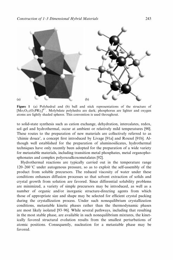
(a) (b)
Figure 1 (a) Polyhedral and (b) ball and stick representations of the structure of[Mo5O15(O3PR)2]
4ÿ. Molybdate polyhedra are dark; phosphorus are lighter and oxygenatoms are lightly shaded spheres. This convention is used throughout.
to solid-state synthesis such as cation exchange, dehydration, intercalates, redox,
sol±gel and hydrothermal, occur at ambient or relatively mild temperatures [90].
These routes to the preparation of new materials are collectively referred to as
`chimie douce', a concept ®rst introduced by Livage [91a] and Rouxel [91b]. Al-
though well established for the preparation of aluminosilicates, hydrothermal
techniques have only recently been adopted for the preparation of a wide variety
for metastable materials, including transition metal phosphates, metal organopho-
sphonates and complex polyoxoalkoxometalates [92].
Hydrothermal reactions are typically carried out in the temperature range
120±260 8C under autogenous pressure, so as to exploit the self-assembly of the
product from soluble precursors. The reduced viscosity of water under these
conditions enhances diffusion processes so that solvent extraction of solids and
crystal growth from solution are favored. Since differential solubility problems
are minimized, a variety of simple precursors may be introduced, as well as a
number of organic and/or inorganic structure-directing agents from which
those of appropriate size and shape may be selected for ef®cient crystal packing
during the crystallization process. Under such nonequilibrium crystallization
conditions, metastable kinetic phases rather than the thermodynamic phases
are most likely isolated [93±96]. While several pathways, including that resulting
in the most stable phase, are available in such nonequilibrium mixtures, the kinet-
ically favored structural evolution results from the smallest perturbations of
atomic positions. Consequently, nucleation for a metastable phase may be
favored.
Construction of 1±3 Dimensional Hybrid Materials 243
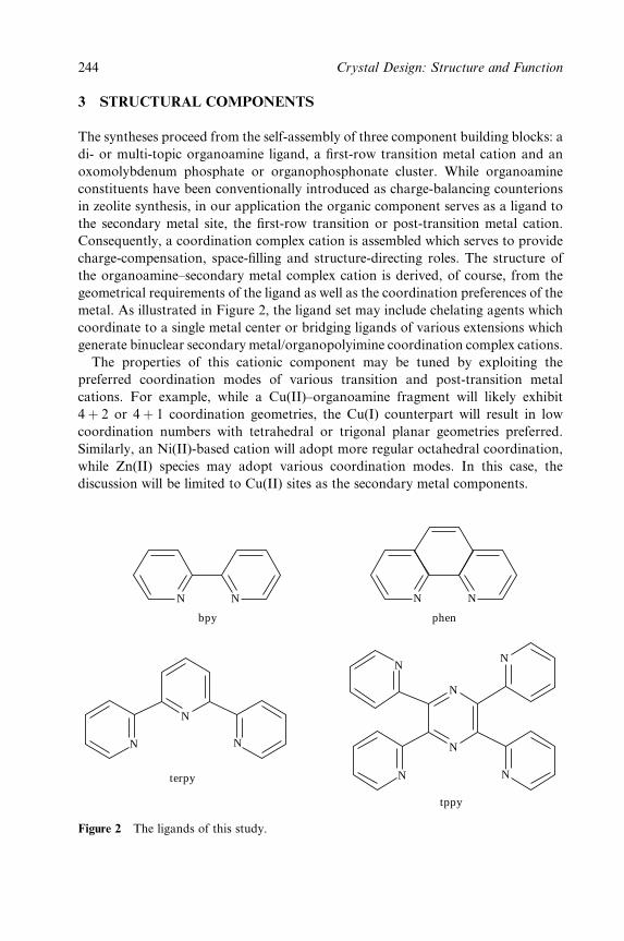
3 STRUCTURAL COMPONENTS
The syntheses proceed from the self-assembly of three component building blocks: a
di- or multi-topic organoamine ligand, a ®rst-row transition metal cation and an
oxomolybdenum phosphate or organophosphonate cluster. While organoamine
constituents have been conventionally introduced as charge-balancing counterions
in zeolite synthesis, in our application the organic component serves as a ligand to
the secondary metal site, the ®rst-row transition or post-transition metal cation.
Consequently, a coordination complex cation is assembled which serves to provide
charge-compensation, space-®lling and structure-directing roles. The structure of
the organoamine±secondary metal complex cation is derived, of course, from the
geometrical requirements of the ligand as well as the coordination preferences of the
metal. As illustrated in Figure 2, the ligand set may include chelating agents which
coordinate to a single metal center or bridging ligands of various extensions which
generate binuclear secondary metal/organopolyimine coordination complex cations.
The properties of this cationic component may be tuned by exploiting the
preferred coordination modes of various transition and post-transition metal
cations. For example, while a Cu(II)±organoamine fragment will likely exhibit
4� 2 or 4� 1 coordination geometries, the Cu(I) counterpart will result in low
coordination numbers with tetrahedral or trigonal planar geometries preferred.
Similarly, an Ni(II)-based cation will adopt more regular octahedral coordination,
while Zn(II) species may adopt various coordination modes. In this case, the
discussion will be limited to Cu(II) sites as the secondary metal components.
N N
N
N
N
N
N
N
N
N
N
N N
bpy phen
terpy
tppy
Figure 2 The ligands of this study.
244 Crystal Design: Structure and Function

The nature of the molybdenum oxide component can be directed to some
extent by the choice of reactions conditions and the presence of other structure-
directing agents, in this instance phosphate and organophosphonates. Thus,
whereas low pH (3±5), short reaction times (10±48 h), and lower temperature
ranges (110±160 8C) favor the formation of molybdate clusters as structural build-
ing blocks, conditions of higher pH (5±8) and more extreme temperatures and
exposure times generally result in architectures in which the secondary metal is
incorporated into a bimetallic oxide network and/or in which the molybdate clus-
ter identity is lost upon fusing into one- or two-dimensional molybdenum oxide
substructures.
Similarly, the introduction of phosphate or organophosphonate components,
RPO32ÿ(R � OH, alkyl, aryl), favors the assembly of molybdophosphate clusters
of the general type {Mo5O15(O5PR)2}4ÿ, which may serve as a structural building
blocks in the construction of complex bimetallic phosphate oxides incorporating
organic components.
The structural versatility of the system is apparent. Modi®cations include: (i)
the identity of the organoimine ligand to the secondary metal site, in this case
Cu(II); (ii) the nature of the phosphate component HOPO32ÿ, RPO3
2ÿor
{O3P(CH2)nPO3}4ÿ; (iii) the tether length of the organic bridge in the diphospho-
nate materials; (iv) the nuclearity of the oxomolybdate cluster; (v) the oxoanion
component, that is, RAsO32ÿ rather than RPO3
2ÿ; (vi) in principle, the identity of
the secondary metal; and (vii) the overall cluster oxidation state, that is, the
introduction of reduced molybdenum centers. The last two possibilities will not be
discussed in this chapter.
For the molybdophosphate building block {Mo5O15(O3PR)2}4ÿ, a conceptually
attractive, albeit naive, scheme for the construction of one- and two-dimensional
structures may be proposed. Thus, building blocks of the type {Mo5O15
(O3POH)2}4ÿ or {Mo5O15(O3PR)2}
4 may be linked through binuclear subunits
such as {Cu2(tppz}4� (tppz-tetrapyridylpyrazine) into one-dimensional chains, as
shown in Figure 3a. Similarly, the {Mo5O15(O3PR)2}4� clusters may be linked
through the alkyl tethers of diphosphonate components {O3P(CH2)nPO3}4ÿ into
chain structures, schematically illustrated in Figure 3b. Combining these two
approaches allows extension into two dimensions, as shown in Figure 3c, an
example of a three component system which inherently contains the structural
information for the self-assembly of a hybrid network.
While the scheme is attractive and in practice of some predictive value,
the structural chemistry of the oxomolybdate±phosphonate/organoimine±copper
system is signi®cantly more complex than the naive model suggests.
Consequently, a variety of molybdophosphate subunits are encountered,
depending on crystallization conditions and the nature of the phosphate compon-
ents, as well as diverse linkage modes of the Cu(II) sites to the molybdophosphate
subunits.
Construction of 1±3 Dimensional Hybrid Materials 245
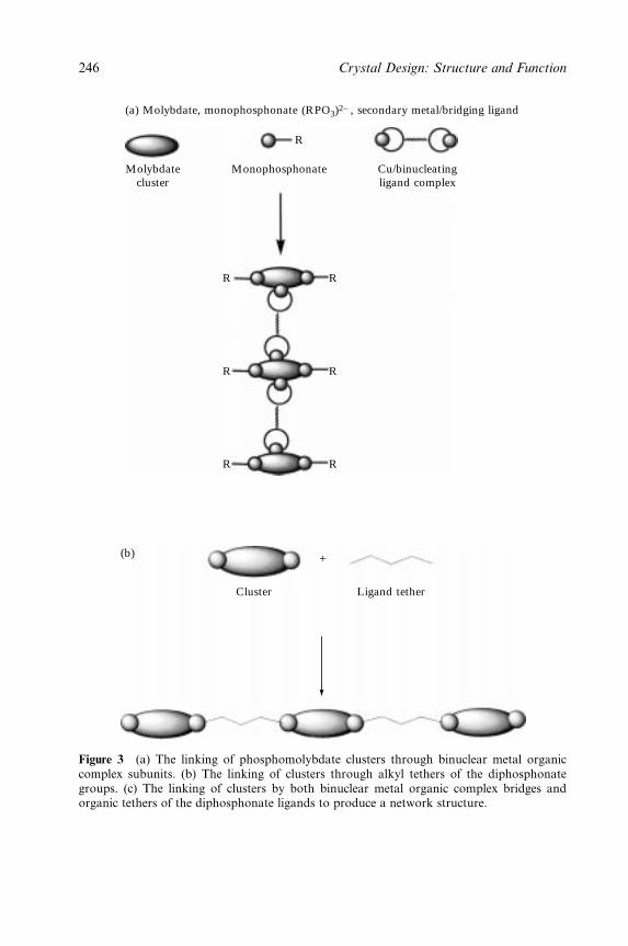
Molybdatecluster
Monophosphonate Cu/binucleatingligand complex
R
R
R
R
R
R
R
(a) Molybdate, monophosphonate (RPO3)2− , secondary metal/bridging ligand
Cluster Ligand tether
(b) +
Figure 3 (a) The linking of phosphomolybdate clusters through binuclear metal organiccomplex subunits. (b) The linking of clusters through alkyl tethers of the diphosphonategroups. (c) The linking of clusters by both binuclear metal organic complex bridges andorganic tethers of the diphosphonate ligands to produce a network structure.
246 Crystal Design: Structure and Function
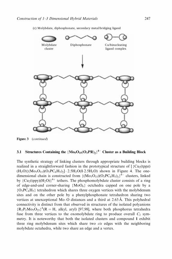
Molybdatecluster
Diphosphonate Cu/binucleatingligand complex
(c) Molybdate, diphosphonate, secondary metal/bridging ligand
Figure 3 (continued)
3.1 Structures Containing the {Mo5O15(O3PR)2}4ÿ Cluster as a Building Block
The synthetic strategy of linking clusters through appropriate building blocks is
realized in a straightforward fashion in the prototypical structure of [ {Cu2(tppz)
(H2O)}(Mo5O15)(O3PC6H5)2] � 2:5H2O(1�2:5H2O) shown in Figure 4. The one-
dimensional chain is constructed from {(Mo5O15)(O3PC6H5)2}4ÿ clusters, linked
by {Cu2(tppy)(H2O)}4� tethers. The phosphomolybdate cluster consists of a ring
of edge-and-and corner-sharing {MoO6} octchedra capped on one pole by a
{O3PC6H5} tetrahedron which shares three oxygen vertices with the molybdenum
sites and on the other pole by a phenylphosphonate tetrahedron sharing two
vertices at unexceptional Mo±O distances and a third at 2.63 AÊ . This polyhedral
connectivity is distinct from that observed in structures of the isolated polyanions
{R2P2Mo5O23}4(R � H, alkyl, aryl) [97,98], where both phosphorus tetrahedra
fuse from three vertices to the oxomolybdate ring to produce overall C2 sym-
metry. It is noteworthy that both the isolated clusters and compound 1 exhibit
three ring molybdenum sites which share two cis edges with the neighboring
molybdate octahedra, while two share an edge and a vertex.
Construction of 1±3 Dimensional Hybrid Materials 247
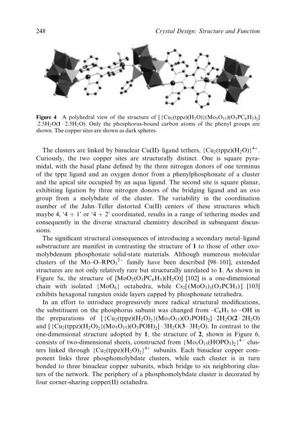
Figure 4 A polyhedral view of the structure of [ {Cu2(tppz)(H2O)}(Mo5O15)(O3PC6H5)2]�2:5H2O(1 � 2:5H2O). Only the phosphorus-bound carbon atoms of the phenyl groups areshown. The copper sites are shown as dark spheres.
The clusters are linked by binuclear Cu(II)±ligand tethers, {Cu2(tppz)(H2O)}4�.
Curiously, the two copper sites are structurally distinct. One is square pyra-
midal, with the basal plane de®ned by the three nitrogen donors of one terminus
of the tppz ligand and an oxygen donor from a phenylphosphonate of a cluster
and the apical site occupied by an aqua ligand. The second site is square planar,
exhibiting ligation by three nitrogen donors of the bridging ligand and an oxo
group from a molybdate of the cluster. The variability in the coordination
number of the Jahn±Teller distorted Cu(II) centers of these structures which
maybe 4, `4 � 1' or `4 � 2' coordinated, results in a range of tethering modes and
consequently in the diverse structural chemistry described in subsequent discus-
sions.
The signi®cant structural consequences of introducing a secondary metal±ligand
substructure are manifest in contrasting the structure of 1 to those of other oxo-
molybdenum phosphonate solid-state materials. Although numerous molecular
clusters of the Mo±O±RPO32ÿ family have been described [98±101], extended
structures are not only relatively rare but structurally unrelated to 1. As shown in
Figure 5a, the structure of [MoO2(O3PC6H5)(H2O)] [102] is a one-dimensional
chain with isolated {MoO6} octahedra, while Cs2[ (MoO3)3(O3PCH3) ] [103]
exhibits hexagonal tungsten oxide layers capped by phosphonate tetrahedra.
In an effort to introduce progressively more radical structural modi®cations,
the substitiuent on the phosphorus subunit was changed from ±C6H5 to ±OH in
the preparations of [ {Cu2(tppz)(H2O)2}(Mo5O15)(O3POH)2] � 2H2O(2 � 2H2O)
and [ {Cu2(tppz)(H2O)2}(Mo5O15)(O3POH)2] � 3H2O(3 � 3H2O). In contrast to the
one-dimensional structure adopted by 1, the structure of 2, shown in Figure 6,
consists of two-dimensional sheets, constructed from {Mo5O15(HOPO3)2}4ÿ clus-
ters linked through {Cu2(tppz)(H2O)2}4� subunits. Each binuclear copper com-
ponent links three phosphomolybdate clusters, while each cluster is in turn
bonded to three binuclear copper subunits, which bridge to six neighboring clus-
ters of the network. The periphery of a phosphomolybdate cluster is decorated by
four corner-sharing copper(II) octahedra.
248 Crystal Design: Structure and Function
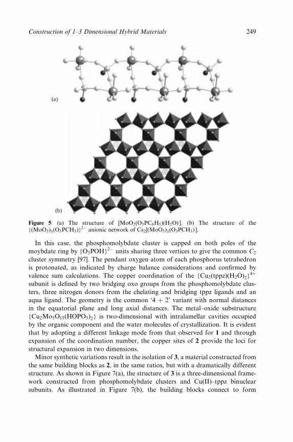
(a)
(b)
Figure 5 (a) The structure of [MoO2(O3PC6H5)(H2O) ]. (b) The structure of the{(MoO3)3(O3PCH3)}
2ÿ anionic network of Cs2[(MoO3)3(O3PCH3) ].
In this case, the phosphomolybdate cluster is capped on both poles of the
moybdate ring by {O3POH}2ÿ units sharing three vertices to give the common C2
cluster symmetry [97]. The pendant oxygen atom of each phosphorus tetrahedron
is protonated, as indicated by charge balance considerations and con®rmed by
valence sum calculations. The copper coordination of the {Cu2(tppz)(H2O)2}4�
subunit is de®ned by two bridging oxo groups from the phosphomolybdate clus-
ters, three nitrogen donors from the chelating and bridging tppz ligands and an
aqua ligand. The geometry is the common `4 � 2' variant with normal distances
in the equatorial plane and long axial distances. The metal±oxide substructure
{Cu2Mo5O15(HOPO3)2} is two-dimensional with intralamellar cavities occupied
by the organic component and the water molecules of crystallization. It is evident
that by adopting a different linkage mode from that observed for 1 and through
expansion of the coordination number, the copper sites of 2 provide the loci for
structural expansion in two dimensions.
Minor synthetic variations result in the isolation of 3, a material constructed from
the same building blocks as 2, in the same ratios, but with a dramatically different
structure. As shown in Figure 7(a), the structure of 3 is a three-dimensional frame-
work constructed from phosphomolybdate clusters and Cu(II)±tppz binuclear
subunits. As illustrated in Figure 7(b), the building blocks connect to form
Construction of 1±3 Dimensional Hybrid Materials 249
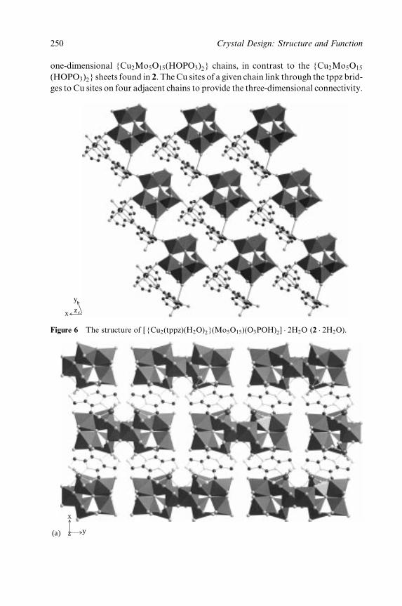
one-dimensional {Cu2Mo5O15(HOPO3)2} chains, in contrast to the {Cu2Mo5O15
(HOPO3)2} sheets found in 2. TheCu sites of a given chain link through the tppz brid-
ges to Cu sites on four adjacent chains to provide the three-dimensional connectivity.
y
x z
Figure 6 The structure of [ {Cu2(tppz)(H2O)2}(Mo5O15)(O3POH)2] � 2H2O (2 � 2H2O).
y
x
z(a)
250 Crystal Design: Structure and Function
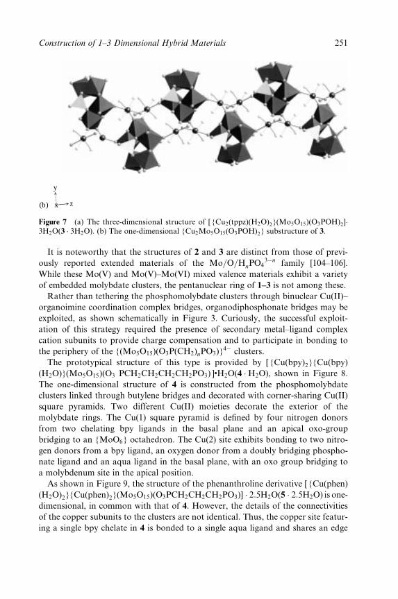
y
x z(b)
Figure 7 (a) The three-dimensional structure of [ {Cu2(tppz)(H2O)2}(Mo5O15)(O3POH)2]�3H2O(3 � 3H2O). (b) The one-dimensional {Cu2Mo5O15(O3POH)2} substructure of 3.
It is noteworthy that the structures of 2 and 3 are distinct from those of previ-
ously reported extended materials of the Mo=O=HnPO43ÿn family [104±106].
While these Mo(V) and Mo(V)±Mo(VI) mixed valence materials exhibit a variety
of embedded molybdate clusters, the pentanuclear ring of 1±3 is not among these.
Rather than tethering the phosphomolybdate clusters through binuclear Cu(II)±
organoimine coordination complex bridges, organodiphosphonate bridges may be
exploited, as shown schematically in Figure 3. Curiously, the successful exploit-
ation of this strategy required the presence of secondary metal±ligand complex
cation subunits to provide charge compensation and to participate in bonding to
the periphery of the {(Mo5O15)(O3P(CH2)nPO3)}4ÿ clusters.
The prototypical structure of this type is provided by [ {Cu(bpy)2}{Cu(bpy)
(H2O)}(Mo5O15)(O3 PCH2CH2CH2CH2PO3) ]�H2O(4 �H2O), shown in Figure 8.
The one-dimensional structure of 4 is constructed from the phosphomolybdate
clusters linked through butylene bridges and decorated with corner-sharing Cu(II)
square pyramids. Two different Cu(II) moieties decorate the exterior of the
molybdate rings. The Cu(1) square pyramid is de®ned by four nitrogen donors
from two chelating bpy ligands in the basal plane and an apical oxo-group
bridging to an {MoO6} octahedron. The Cu(2) site exhibits bonding to two nitro-
gen donors from a bpy ligand, an oxygen donor from a doubly bridging phospho-
nate ligand and an aqua ligand in the basal plane, with an oxo group bridging to
a molybdenum site in the apical position.
As shown in Figure 9, the structure of the phenanthroline derivative [ {Cu(phen)
(H2O)2}{Cu(phen)2}(Mo5O15)(O3PCH2CH2CH2PO3)] � 2:5H2O(5 � 2:5H2O) is one-
dimensional, in common with that of 4. However, the details of the connectivities
of the copper subunits to the clusters are not identical. Thus, the copper site featur-
ing a single bpy chelate in 4 is bonded to a single aqua ligand and shares an edge
Construction of 1±3 Dimensional Hybrid Materials 251
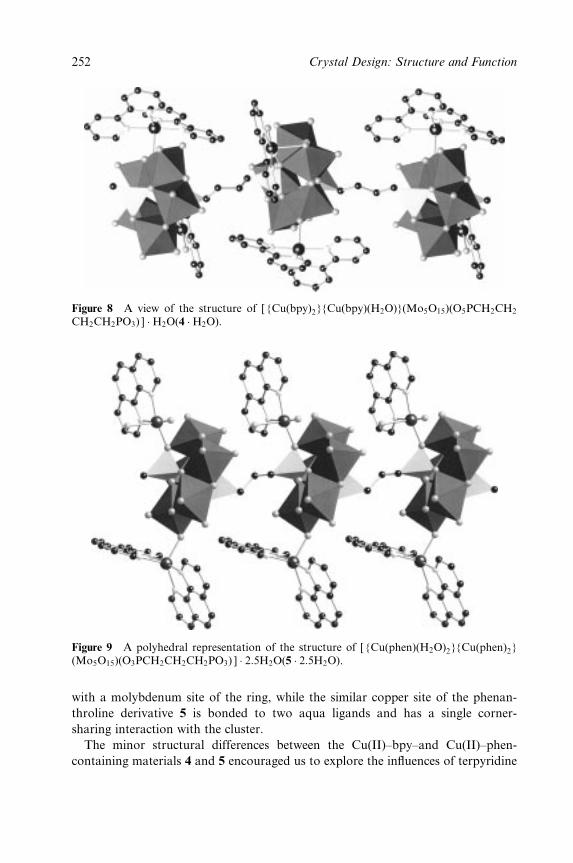
Figure 8 A view of the structure of [ {Cu(bpy)2}{Cu(bpy)(H2O)}(Mo5O15)(O5PCH2CH2
CH2CH2PO3) ] �H2O(4 �H2O).
Figure 9 A polyhedral representation of the structure of [ {Cu(phen)(H2O)2}{Cu(phen)2}(Mo5O15)(O3PCH2CH2CH2PO3) ] � 2:5H2O(5 � 2:5H2O).
with a molybdenum site of the ring, while the similar copper site of the phenan-
throline derivative 5 is bonded to two aqua ligands and has a single corner-
sharing interaction with the cluster.
The minor structural differences between the Cu(II)±bpy±and Cu(II)±phen-
containing materials 4 and 5 encouraged us to explore the in¯uences of terpyridine
252 Crystal Design: Structure and Function
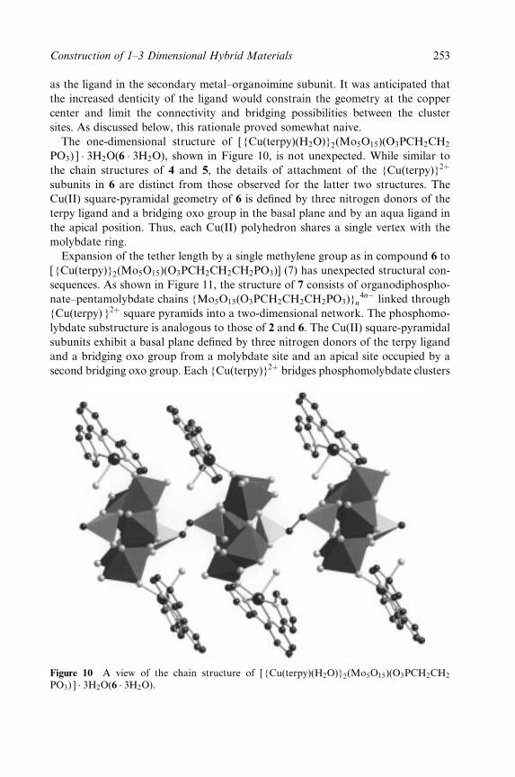
as the ligand in the secondary metal±organoimine subunit. It was anticipated that
the increased denticity of the ligand would constrain the geometry at the copper
center and limit the connectivity and bridging possibilities between the cluster
sites. As discussed below, this rationale proved somewhat naive.
The one-dimensional structure of [ {Cu(terpy)(H2O)}2(Mo5O15)(O3PCH2CH2
PO3) ] � 3H2O(6 � 3H2O), shown in Figure 10, is not unexpected. While similar to
the chain structures of 4 and 5, the details of attachment of the {Cu(terpy)}2�
subunits in 6 are distinct from those observed for the latter two structures. The
Cu(II) square-pyramidal geometry of 6 is de®ned by three nitrogen donors of the
terpy ligand and a bridging oxo group in the basal plane and by an aqua ligand in
the apical position. Thus, each Cu(II) polyhedron shares a single vertex with the
molybdate ring.
Expansion of the tether length by a single methylene group as in compound 6 to
[ {Cu(terpy)}2(Mo5O15)(O3PCH2CH2CH2PO3)] (7) has unexpected structural con-
sequences. As shown in Figure 11, the structure of 7 consists of organodiphospho-
nate±pentamolybdate chains {Mo5O15(O3PCH2CH2CH2PO3)}n4nÿ linked through
{Cu(terpy) }2� square pyramids into a two-dimensional network. The phosphomo-
lybdate substructure is analogous to those of 2 and 6. The Cu(II) square-pyramidal
subunits exhibit a basal plane de®ned by three nitrogen donors of the terpy ligand
and a bridging oxo group from a molybdate site and an apical site occupied by a
second bridging oxo group. Each {Cu(terpy)}2� bridges phosphomolybdate clusters
Figure 10 A view of the chain structure of [ {Cu(terpy)(H2O)}2(Mo5O15)(O3PCH2CH2
PO3) ] � 3H2O(6 � 3H2O).
Construction of 1±3 Dimensional Hybrid Materials 253

y
x
z
Figure 11 The structure of [ {Cu(terpy)}2(Mo5O15)(O3PCH2CH2CH2PO3) ](7). The terpycarbon atoms have been omitted.
from two adjacent {(Mo5O15)(O3PCH2CH2CH2PO3)}n4nÿ chains. Consequently,
the structure may be alternatively described as copper molybdate chains
{Cu2Mo5O15}n4n� linked through propylenediphosphonate ligands into a two-
dimensional network. The cross linking {Cu2Mo5O15}n4n� and { (Mo5O15)
(O3PCH2CH2CH2PO3)}n4nÿ chains intersect at an angle of ca 788.
Based on the synthetic strategies schematically illustrated in Figure 3a and b, the
naive expectation was the isolation of one-dimensional chains of tethered clusters.
While this was realized in structures 1, 4, 5 and 6, compounds 2 and 7 are two-
dimensional whereas 3 is three-dimensional, re¯ecting the versatility of the linkage
modes adopted by the secondary metal components. However, it was anticipated
that combining a diphosphonate linker with a binuclear Cu(II)±organoimine sub-
unit would result in a two-dimensional material, with clusters linked in one direc-
tion by the diphosphonate and cross-tethered by the binuclear binder. The
implementation of this strategy is re¯ected in [ {Cu2(tppz)(H2O)2}(Mo5O15)
(O3PCH2CH2PO3) ] � 5:5H2O(8 � 5:5H2O), shown in Figure 12. The structure con-
sists of one-dimensional {(Mo5O15)(O3PCH2CH2PO3)}n4nÿ chains linked through
{Cu2(tppz)(H2O)2}4� subunits into a two-dimensional network. While the molyb-
dophosphonate chain of 8 is constructed from {(Mo5O15)(O3P-)2} clusters identical
with those described for 2 and 7, the dispositions of the secondary metal±ligand
254 Crystal Design: Structure and Function
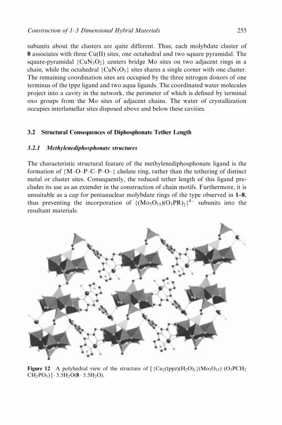
subunits about the clusters are quite different. Thus, each molybdate cluster of
8 associates with three Cu(II) sites, one octahedral and two square pyramidal. The
square-pyramidal {CuN3O2} centers bridge Mo sites on two adjacent rings in a
chain, while the octahedral {CuN3O3} sites shares a single corner with one cluster.
The remaining coordination sites are occupied by the three nitrogen donors of one
terminus of the tppz ligand and two aqua ligands. The coordinated water molecules
project into a cavity in the network, the perimeter of which is de®ned by terminal
oxo groups from the Mo sites of adjacent chains. The water of crystallization
occupies interlamellar sites disposed above and below these cavities.
3.2 Structural Consequences of Diphosphonate Tether Length
3.2.1 Methylenediphosphonate structures
The characteristic structural feature of the methylenediphosphonate ligand is the
formation of {M±O±P±C±P±O±} chelate ring, rather than the tethering of distinct
metal or cluster sites. Consequently, the reduced tether length of this ligand pre-
cludes its use as an extender in the construction of chain motifs. Furthermore, it is
unsuitable as a cap for pentanuclear molybdate rings of the type observed in 1±8,
thus preventing the incorporation of {(Mo5O15)(O3PR)2}4ÿ subunits into the
resultant materials.
Figure 12 A polyhedral view of the structure of [ {Cu2(tppz)(H2O)2}(Mo5O15) (O3PCH2
CH2PO3) ] � 5:5H2O(8 � 5:5H2O).
Construction of 1±3 Dimensional Hybrid Materials 255
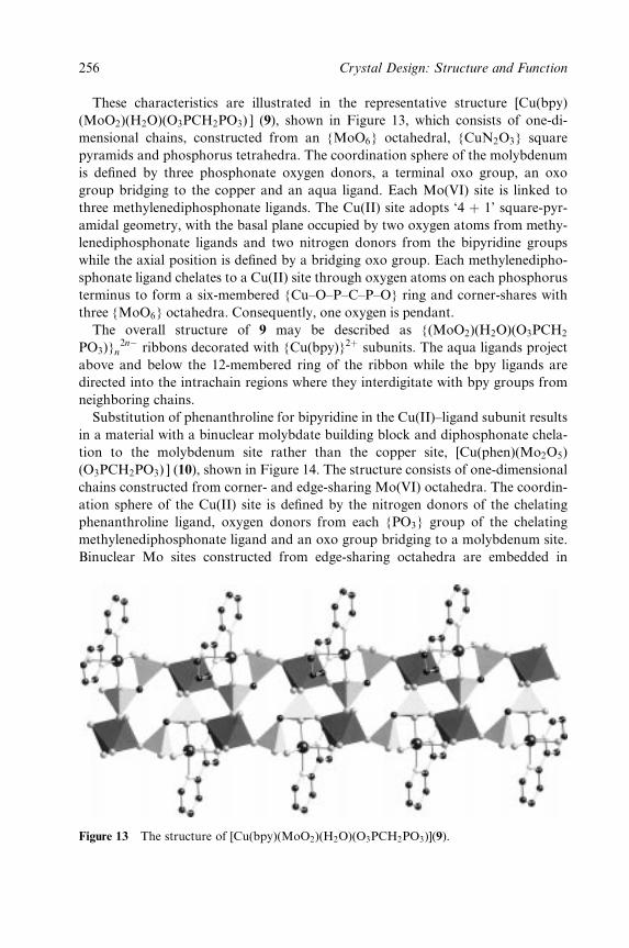
These characteristics are illustrated in the representative structure [Cu(bpy)
(MoO2)(H2O)(O3PCH2PO3) ] (9), shown in Figure 13, which consists of one-di-
mensional chains, constructed from an {MoO6} octahedral, {CuN2O3} square
pyramids and phosphorus tetrahedra. The coordination sphere of the molybdenum
is de®ned by three phosphonate oxygen donors, a terminal oxo group, an oxo
group bridging to the copper and an aqua ligand. Each Mo(VI) site is linked to
three methylenediphosphonate ligands. The Cu(II) site adopts `4 � 1' square-pyr-
amidal geometry, with the basal plane occupied by two oxygen atoms from methy-
lenediphosphonate ligands and two nitrogen donors from the bipyridine groups
while the axial position is de®ned by a bridging oxo group. Each methylenedipho-
sphonate ligand chelates to a Cu(II) site through oxygen atoms on each phosphorus
terminus to form a six-membered {Cu±O±P±C±P±O} ring and corner-shares with
three {MoO6} octahedra. Consequently, one oxygen is pendant.
The overall structure of 9 may be described as {(MoO2)(H2O)(O3PCH2
PO3)}n2nÿ ribbons decorated with {Cu(bpy)}2� subunits. The aqua ligands project
above and below the 12-membered ring of the ribbon while the bpy ligands are
directed into the intrachain regions where they interdigitate with bpy groups from
neighboring chains.
Substitution of phenanthroline for bipyridine in the Cu(II)±ligand subunit results
in a material with a binuclear molybdate building block and diphosphonate chela-
tion to the molybdenum site rather than the copper site, [Cu(phen)(Mo2O5)
(O3PCH2PO3) ] (10), shown in Figure 14. The structure consists of one-dimensional
chains constructed from corner- and edge-sharing Mo(VI) octahedra. The coordin-
ation sphere of the Cu(II) site is de®ned by the nitrogen donors of the chelating
phenanthroline ligand, oxygen donors from each {PO3} group of the chelating
methylenediphosphonate ligand and an oxo group bridging to a molybdenum site.
Binuclear Mo sites constructed from edge-sharing octahedra are embedded in
Figure 13 The structure of [Cu(bpy)(MoO2)(H2O)(O3PCH2PO3)](9).
256 Crystal Design: Structure and Function
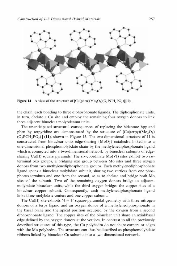
Figure 14 A view of the structure of [Cu(phen)(Mo2O5)(O3PCH2PO3)](10).
the chain, each bonding to three diphosphonate ligands. The diphosphonate units,
in turn, chelate a Cu site and employ the remaining four oxygen donors to link
three adjacent binuclear molybdenum units.
The unanticipated structural consequences of replacing the bidentate bpy and
phen by terpyridine are demonstrated by the structure of [Cu(terpy)(Mo2O5)
(O3PCH2PO3) ] (11), shown in Figure 15. The two-dimensional structure of 11 is
constructed from binuclear units edge-sharing {MoO6} octahedra linked into a
one-dimensional phosphomolybdate chain by the methylenediphosphonate ligand
which is connected into a two-dimensional network by binuclear subunits of edge-
sharing Cu(II) square pyramids. The six-coordinate Mo(VI) sites exhibit two cis-
terminal oxo groups, a bridging oxo group between Mo sites and three oxygen
donors from two methylenediphosphonate groups. Each methylenediphosphonate
ligand spans a binuclear molybdate subunit, sharing two vertices from one phos-
phorus terminus and one from the second, so as to chelate and bridge both Mo
sites of the subunit. Two of the remaining oxygen donors bridge to adjacent
molybdate binuclear units, while the third oxygen bridges the copper sites of a
binuclear copper subunit. Consequently, each methylenediphosphonate ligand
links three molybdate centers and one copper subunit.
The Cu(II) site exhibits `4 � 1' square-pyramidal geometry with three nitrogen
donors of a terpy ligand and an oxygen donor of a methylenediphosphonate in
the basal plane and the apical position occupied by the oxygen from a second
diphosphonate ligand. The copper sites of the binuclear unit share an axial/basal
edge de®ned by the oxygen donors at the vertices. In contrast to all the previously
described structures of this type, the Cu polyhedra do not share corners or edges
with the Mo polyhedra. The structure can thus be described as phosphomolybdate
ribbons linked by binuclear Cu subunits into a two-dimensional network.
Construction of 1±3 Dimensional Hybrid Materials 257
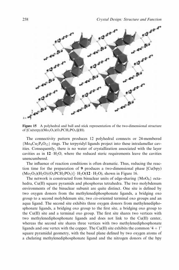
x
z y
Figure 15 A polyhedral and ball and stick representation of the two-dimensional structureof [Cu(terpy)(Mo2O5)(O3PCH2PO3)](11).
The connectivity pattern produces 12 polyhedral connects or 24-membered
{Mo4Cu2P6O12} rings. The terpyridyl ligands project into these intralamellar cav-
ities. Consequently, there is no water of crystallization associated with the layer
cavities as in 12 �H2O, where the reduced steric requirements leave the cavities
unencumbered.
The in¯uence of reaction conditions is often dramatic. Thus, reducing the reac-
tion time for the preparation of 9 produces a two-dimensional phase [Cu(bpy)
(Mo2O5)(H2O) (O3PCH2PO3) ] �H2O(12 �H2O), shown in Figure 16.
The network is constructed from binuclear units of edge-sharing {MoO6} octa-
hedra, Cu(II) square pyramids and phosphorus tetrahedra. The two molybdenum
environments of the binuclear subunit are quite distinct. One site is de®ned by
two oxygen donors from the methylenediphosphonate ligands, a bridging oxo
group to a second molybdenum site, two cis-oriented terminal oxo groups and an
aqua ligand. The second site exhibits three oxygen donors from methylenedipho-
sphonate ligands, a bridging oxo group to the ®rst site, a bridging oxo group to
the Cu(II) site and a terminal oxo group. The ®rst site shares two vertices with
two methylenediphosphonate ligands and does not link to the Cu(II) center,
whereas the second site shares three vertices with two methylenediphosphonate
ligands and one vertex with the copper. The Cu(II) site exhibits the common `4 � 1'
square pyramidal geometry, with the basal plane de®ned by two oxygen atoms of
a chelating methylenediphosphonate ligand and the nitrogen donors of the bpy
258 Crystal Design: Structure and Function
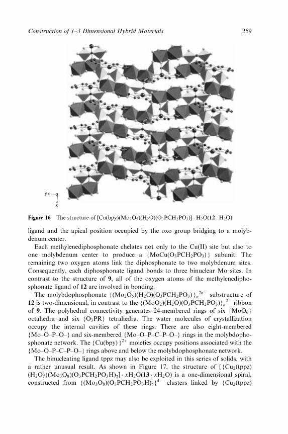
y z
x
Figure 16 The structure of [Cu(bpy)(Mo2O5)(H2O)(O3PCH2PO3)] �H2O(12 �H2O).
ligand and the apical position occupied by the oxo group bridging to a molyb-
denum center.
Each methylenediphosphonate chelates not only to the Cu(II) site but also to
one molybdenum center to produce a {MoCu(O3PCH2PO3) } subunit. The
remaining two oxygen atoms link the diphosphonate to two molybdenum sites.
Consequently, each diphosphonate ligand bonds to three binuclear Mo sites. In
contrast to the structure of 9, all of the oxygen atoms of the methylenedipho-
sphonate ligand of 12 are involved in bonding.
The molybdophosphonate {(Mo2O5)(H2O)(O3PCH2PO3) }n2nÿ substructure of
12 is two-dimensional, in contrast to the {(MoO2)(H2O)(O3PCH2PO3)}n2ÿ ribbon
of 9. The polyhedral connectivity generates 24-membered rings of six {MoO6}
octahedra and six {O3PR} tetrahedra. The water molecules of crystallization
occupy the internal cavities of these rings. There are also eight-membered
{Mo±O±P±O±} and six-membered {Mo±O±P±C±P±O±} rings in the molybdopho-
sphonate network. The {Cu(bpy) }2� moieties occupy positions associated with the
{Mo±O±P±C±P±O±} rings above and below the molybdophosphonate network.
The binucleating ligand tppz may also be exploited in this series of solids, with
a rather unusual result. As shown in Figure 17, the structure of [ {Cu2(tppz)
(H2O)}(Mo3O8)(O3PCH2PO3H)2] � xH2O(13 � xH2O) is a one-dimensional spiral,
constructed from {(Mo3O8)(O3PCH2PO3H)2}4ÿ clusters linked by {Cu2(tppz)
Construction of 1±3 Dimensional Hybrid Materials 259
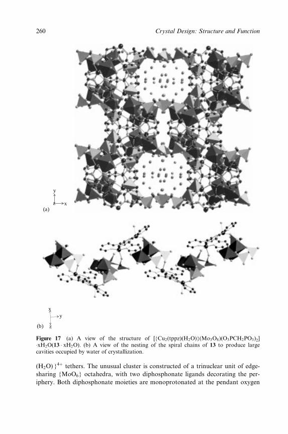
y
z x(a)
xy
z(b)
Figure 17 (a) A view of the structure of [{Cu2(tppz)(H2O)}(Mo3O8)(O3PCH2PO3)2]�xH2O(13 � xH2O). (b) A view of the nesting of the spiral chains of 13 to produce largecavities occupied by water of crystallization.
(H2O) }4� tethers. The unusual cluster is constructed of a trinuclear unit of edge-
sharing {MoO6} octahedra, with two diphosphonate ligands decorating the per-
iphery. Both diphosphonate moieties are monoprotonated at the pendant oxygen
260 Crystal Design: Structure and Function
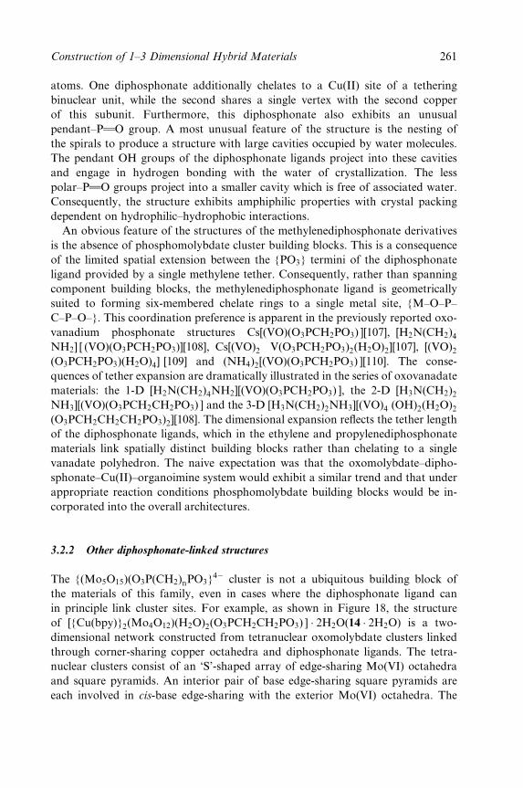
atoms. One diphosphonate additionally chelates to a Cu(II) site of a tethering
binuclear unit, while the second shares a single vertex with the second copper
of this subunit. Furthermore, this diphosphonate also exhibits an unusual
pendant±PwwO group. A most unusual feature of the structure is the nesting of
the spirals to produce a structure with large cavities occupied by water molecules.
The pendant OH groups of the diphosphonate ligands project into these cavities
and engage in hydrogen bonding with the water of crystallization. The less
polar±PwwO groups project into a smaller cavity which is free of associated water.
Consequently, the structure exhibits amphiphilic properties with crystal packing
dependent on hydrophilic±hydrophobic interactions.
An obvious feature of the structures of the methylenediphosphonate derivatives
is the absence of phosphomolybdate cluster building blocks. This is a consequence
of the limited spatial extension between the {PO3} termini of the diphosphonate
ligand provided by a single methylene tether. Consequently, rather than spanning
component building blocks, the methylenediphosphonate ligand is geometrically
suited to forming six-membered chelate rings to a single metal site, {M±O±P±
C±P±O±}. This coordination preference is apparent in the previously reported oxo-
vanadium phosphonate structures Cs[(VO)(O3PCH2PO3) ][107], [H2N(CH2)4NH2] [ (VO)(O3PCH2PO3)][108], Cs[(VO)2 V(O3PCH2PO3)2(H2O)2][107], [(VO)2(O3PCH2PO3)(H2O)4] [109] and (NH4)2[(VO)(O3PCH2PO3) ][110]. The conse-
quences of tether expansion are dramatically illustrated in the series of oxovanadate
materials: the 1-D [H2N(CH2)4NH2][(VO)(O3PCH2PO3) ], the 2-D [H3N(CH2)2NH3][(VO)(O3PCH2CH2PO3) ] and the 3-D [H3N(CH2)2NH3][(VO)4 (OH)2(H2O)2(O3PCH2CH2CH2PO3)2][108]. The dimensional expansion re¯ects the tether length
of the diphosphonate ligands, which in the ethylene and propylenediphosphonate
materials link spatially distinct building blocks rather than chelating to a single
vanadate polyhedron. The naive expectation was that the oxomolybdate±dipho-
sphonate±Cu(II)±organoimine system would exhibit a similar trend and that under
appropriate reaction conditions phosphomolybdate building blocks would be in-
corporated into the overall architectures.
3.2.2 Other diphosphonate-linked structures
The {(Mo5O15)(O3P(CH2)nPO3}4ÿ cluster is not a ubiquitous building block of
the materials of this family, even in cases where the diphosphonate ligand can
in principle link cluster sites. For example, as shown in Figure 18, the structure
of [{Cu(bpy)}2(Mo4O12)(H2O)2(O3PCH2CH2PO3) ] � 2H2O(14 � 2H2O) is a two-
dimensional network constructed from tetranuclear oxomolybdate clusters linked
through corner-sharing copper octahedra and diphosphonate ligands. The tetra-
nuclear clusters consist of an `S'-shaped array of edge-sharing Mo(VI) octahedra
and square pyramids. An interior pair of base edge-sharing square pyramids are
each involved in cis-base edge-sharing with the exterior Mo(VI) octahedra. The
Construction of 1±3 Dimensional Hybrid Materials 261
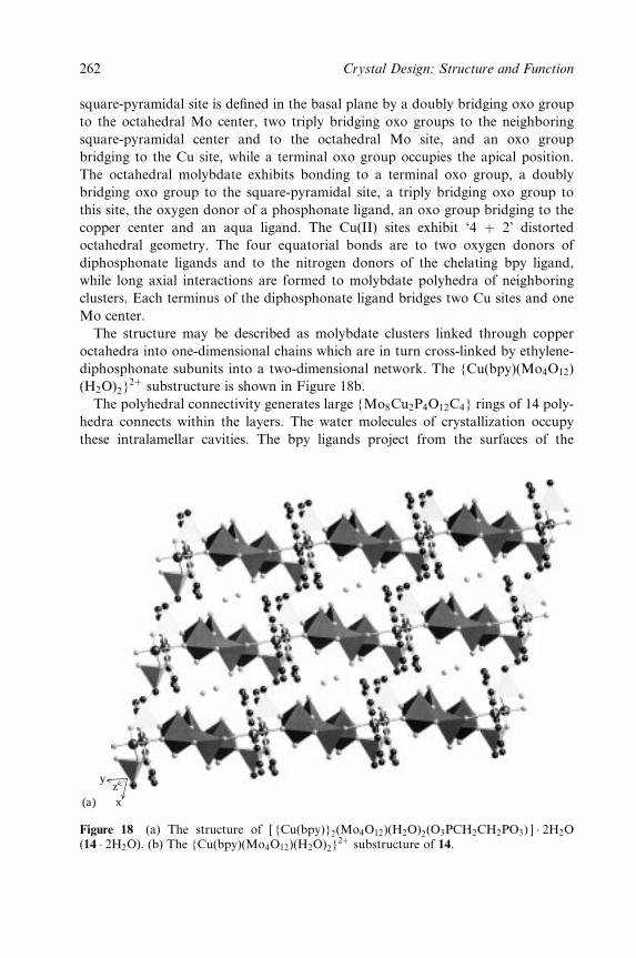
square-pyramidal site is de®ned in the basal plane by a doubly bridging oxo group
to the octahedral Mo center, two triply bridging oxo groups to the neighboring
square-pyramidal center and to the octahedral Mo site, and an oxo group
bridging to the Cu site, while a terminal oxo group occupies the apical position.
The octahedral molybdate exhibits bonding to a terminal oxo group, a doubly
bridging oxo group to the square-pyramidal site, a triply bridging oxo group to
this site, the oxygen donor of a phosphonate ligand, an oxo group bridging to the
copper center and an aqua ligand. The Cu(II) sites exhibit `4 � 2' distorted
octahedral geometry. The four equatorial bonds are to two oxygen donors of
diphosphonate ligands and to the nitrogen donors of the chelating bpy ligand,
while long axial interactions are formed to molybdate polyhedra of neighboring
clusters. Each terminus of the diphosphonate ligand bridges two Cu sites and one
Mo center.
The structure may be described as molybdate clusters linked through copper
octahedra into one-dimensional chains which are in turn cross-linked by ethylene-
diphosphonate subunits into a two-dimensional network. The {Cu(bpy)(Mo4O12)
(H2O)2}2� substructure is shown in Figure 18b.
The polyhedral connectivity generates large {Mo8Cu2P4O12C4} rings of 14 poly-
hedra connects within the layers. The water molecules of crystallization occupy
these intralamellar cavities. The bpy ligands project from the surfaces of the
yzx(a)
Figure 18 (a) The structure of [ {Cu(bpy)}2(Mo4O12)(H2O)2(O3PCH2CH2PO3) ] � 2H2O(14 � 2H2O). (b) The {Cu(bpy)(Mo4O12)(H2O)2}
2� substructure of 14.
262 Crystal Design: Structure and Function

(b)
Figure 18 (continued )
layers into the interlamellar spaces and interdigitate with rings from adjacent
layers. The structure of 14�2H2O is isomorphous with that of the phenanthroline
derivative [ {Cu(phen)}2(Mo4O12)(H2O)2(O3PCH2CH2PO3) ] � 2H2O(15 � 2H2O).
Expansion of the tether length to three methylene groups in the propylenedipho-
sphonate derivative [Cu(bpy)(Mo2O5)(O3PCH2CH2CH2PO3)] (16) has unexpected
structural consequences. As shown in Figure 19a, the structure of 16 is layered and
constructed of binuclear units of face-sharing molybdate octahedra linked through
copper octahedra and phosphorus tetrahedra. The Mo geometries are de®ned by
three oxygen donors from diphosphonate ligands, a doubly bridging oxo group to
the second Mo site of the binuclear unit, an oxo group bridging to a Cu(II) site and
a terminal oxo group. The Cu(II) site exhibits `4 � 2' six coordination with an
equatorial plane de®ned by the nitrogen donors of the chelating bpy ligand and
two oxygen donors from diphosphonate groups; the long axial interactions are with
oxo groups from two neighboring molybdate binuclear units.
The most unusual feature of the structure of 16 is the disposition of the propyle-
nediphosphonate ligand. Two oxygen donors of each phosphorus terminus link to
molybdate groups of two neighboring binuclear subunits; consequently, each
diphosphonate group bridges four binuclear subunits. Curiously, the remaining
oxygen donors are employed in chelation to a single Cu(II) center, such that the
diphosphonate folds to form a most unusual eight-membered {Cu±O±P±C±C±C±
P±O±} chelate ring. One consequence of this bonding pattern is to produce a much
less open network than that associated with 14�2H2O, a feature consistent with the
absence of water of crystallization within layers of 16.
The copper molybdate substructure of 16, {Cu(bpy)(Mo2O5)}4�, is a one-
dimensional chain of binuclearmolybdate subunits bridged by {Cu(bpy)}2�moieties.
These chains are connected in turn by the propylenediphosphonate ligands.As shown
Construction of 1±3 Dimensional Hybrid Materials 263
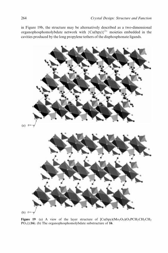
in Figure 19b, the structure may be alternatively described as a two-dimensional
organophosphomolybdate network with {Cu(bpy)}2� moieties embedded in the
cavities produced by the long propylene tethers of the disphosphonate ligands.
(a)
x
yz
yz
x
(b)
Figure 19 (a) A view of the layer structure of [Cu(bpy)(Mo2O5)(O3PCH2CH2CH2
PO3)}(16). (b) The organophosphomolybdate substructure of 16.
264 Crystal Design: Structure and Function
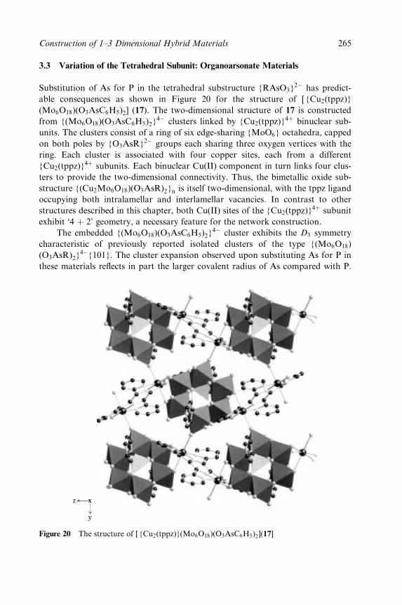
3.3 Variation of the Tetrahedral Subunit: Organoarsonate Materials
Substitution of As for P in the tetrahedral substructure {RAsO3}2ÿ has predict-
able consequences as shown in Figure 20 for the structure of [ {Cu2(tppz)}
(Mo6O18)(O3AsC6H5)2] (17). The two-dimensional structure of 17 is constructed
from {(Mo6O18)(O3AsC6H5)2}4ÿ clusters linked by {Cu2(tppz)}4� binuclear sub-
units. The clusters consist of a ring of six edge-sharing {MoO6} octahedra, capped
on both poles by {O3AsR}2ÿ groups each sharing three oxygen vertices with the
ring. Each cluster is associated with four copper sites, each from a different
{Cu2(tppz)}4� subunits. Each binuclear Cu(II) component in turn links four clus-
ters to provide the two-dimensional connectivity. Thus, the bimetallic oxide sub-
structure {(Cu2Mo6O18)(O3AsR)2}n is itself two-dimensional, with the tppz ligand
occupying both intralamellar and interlamellar vacancies. In contrast to other
structures described in this chapter, both Cu(II) sites of the {Cu2(tppz)}4� subunit
exhibit `4 � 2' geometry, a necessary feature for the network construction.
The embedded {(Mo6O18)(O3AsC6H5)2}4ÿ cluster exhibits the D3 symmetry
characteristic of previously reported isolated clusters of the type {(Mo6O18)
(O3AsR)2}4ÿ{101}. The cluster expansion observed upon substituting As for P in
these materials re¯ects in part the larger covalent radius of As compared with P.
y
xz
Figure 20 The structure of [ {Cu2(tppz)}(Mo6O18)(O3AsC6H5)2](17]
Construction of 1±3 Dimensional Hybrid Materials 265
This in turn results in an expansion of the O3 face of the tetrahedral {O3ER}
subunit, which fuses to the molybdate ring. The O � � �O distances for this triangu-
lar face are ca 2.53AÊ for phosphorus and 2.80AÊ for As. This increase in the
dimensions of this structural building block allows a concomitant expansion of
the molybdate ring nuclearity.
4 TRENDS AND CLASSIFICATIONS
The structures of this study exhibit a remarkable range of component substruc-
tures and polyhedral connectivities. To date, the family of materials of the type
oxomolybdate±REO32ÿ±Cu(II)±organoimine is represented by E � As and, P and
by the organoimine ligands 2, 20-bipyridine, o-phenanthroline, 2, 20: 60, 200-terpyr-
idine and tetra(4-pyridyl)pyrazine. While the {(Mo5O15)(O3P-)2}4ÿ cluster is a
recurring motif, it is not ubiquitous, as manifested in the structural summary of
Table 1. Despite the overall complexity of the structural characteristics of this
family of materials, a relatively simple method of classi®cation based on the
nuclearity of the molybdenum subunits embedded within the solid has been
adopted. Thus, six subclasses of materials have been identi®ed, incorporating
{MoO6}x subunits with x � 1, 2, 3, 4, 5 and 6.
The structural summary evokes a number of observations. While a signi®cant
database has been compiled for this unusually fruitful family of materials, it is
clear that the set of compounds is not exhaustive in view of the structural vari-
ability associated with the constituent building blocks. This latter point is re¯ected
in the different coordination geometries accessible for Mo(VI), including tetrahe-
dral, square-pyramidal and octahedral, in addition to the aggregation for molyb-
denum polyhedra into oligomers of various nuclearities. Furthermore, the
diphosphonate ligand may adopt a variety of coordination modes with respect to
the molybdate subunit and the secondary metal component, which also enjoys
considerable latitude in coordination geometry and polyhedral connectivity to the
molybdophosphonate substructure. Finally, coordinated water molecules are
often constituents of both the molybdenum and the copper coordination sphere in
phases which have been prepared hydrothermally at moderate temperature. Thus,
it may be anticipated that for a given combination of organoimine coligand to the
Cu(II) subunit and organodiphosphonate linker more than one phase may be
accessible by appropriate manipulation of the hydrothermal conditions. Hydro-
thermal parameter space, which includes stoichiometries, pH, temperature and ®ll
volume, is vast and even minor variations can result in the isolation of new
metastable phases. This point is illustrated by the isolation of two phases 9 and
12 �H2O for the methylenediphosphonate and 2, 20-bipyridine combination
of ligands. It is likely that other combinations of organodiphosphonates and
266 Crystal Design: Structure and Function
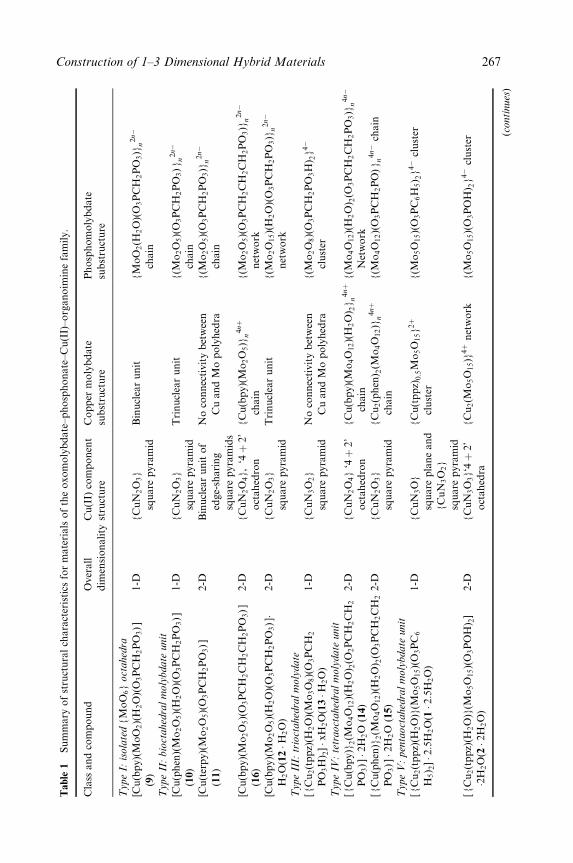
Table
1Sum
mary
ofst
ruct
ura
lch
ara
cter
istics
for
mate
rials
ofth
eoxom
oly
bdate
±phosp
honate
±C
u(I
I)±org
anoim
ine
fam
ily.
Cla
ssand
com
pound
Over
all
dim
ensionality
Cu(I
I)co
mponen
t
stru
cture
Copper
moly
bdate
subst
ruct
ure
Phosp
hom
oly
bdate
subst
ruct
ure
Type
I:isola
ted
{M
oO
6}
oct
ahed
ra
[Cu(b
py)(
MoO
2)(
H2O
)(O
3PC
H2PO
3)]
(9)
1-D
{C
uN
2O
3}
square
pyra
mid
Bin
ucl
ear
unit
{M
oO
2(H
2O
)(O
3PC
H2PO
3)}
n2nÿ
chain
Type
II:bio
ctahed
ralm
oly
bdate
unit
[Cu(p
hen
)(M
o2O
5)(
H2O
)(O
3PC
H2PO
3)]
(10)
1-D
{C
uN
2O
3}
square
pyra
mid
Trinucl
ear
unit
{(M
o2O
5)(
O3PC
H2PO
3)}
n2nÿ
chain
[Cu(ter
py)(
Mo
2O
5)(
O3PC
H2PO
3)]
(11)
2-D
Bin
ucl
ear
unit
of
edge-
sharing
square
pyra
mid
s
No
connec
tivity
bet
wee
n
Cu
and
Mo
poly
hed
ra
{(M
o2O
5)(
O3PC
H2PO
3)}
n2nÿ
chain
[Cu(b
py)(
Mo
2O
5)(
O3PC
H2C
H2C
H2PO
3)]
(16)
2-D
{C
uN
2O
4},
`4�
2'
oct
ahed
ron
{C
u(b
py)(M
o2O
5)}
n4n�
chain
{(M
o2O
5)(
O3PC
H2C
H2C
H2PO
3)}
n2nÿ
net
work
[Cu(b
py)(
Mo
2O
5)(
H2O
)(O
3PC
H2PO
3)]�
H2O
(12�H
2O
)
2-D
{C
uN
2O
3}
square
pyra
mid
Trinucl
ear
unit
{(M
o2O
15)(
H2O
)(O
3PC
H2PO
3)}
n2nÿ
net
work
Type
III:
trio
ctahed
ralm
oly
date
[{C
u2(t
ppz)
(H2O
)(M
o3O
8)(
O3PC
H2
PO
3H
) 2]�x
H2O
(13�H
2O
)
1-D
{C
uN
3O
2}
square
pyra
mid
No
connec
tivity
bet
wee
n
Cu
and
Mo
poly
hed
ra
{(M
o2O
8)(
O3PC
H2PO
3H
) 2}
4ÿ
clust
er
Type
IV:te
traoct
ahed
ralm
oly
date
unit
[{C
u(b
py)}
2(M
o4O
12)(
H2O
) 2(O
2PC
H2C
H2
PO
3)]�2
H2O
(14)
2-D
{C
uN
2O
4}
`4�
2'
oct
ahed
ron
{C
u(b
py)(M
o4O
12)(
H2O
) 2}
n4n�
chain
{(M
o4O
12)(
H2O
) 2(O
3PC
H2C
H2PO
3)}
n4nÿ
Net
work
[{C
u(p
hen
)}2(M
o4O
12)(
H2O
) 2(O
3PC
H2C
H2
PO
3)]�2
H2O
(15)
2-D
{C
uN
2O
3}
square
pyra
mid
{C
u2(p
hen
) 2(M
o4O
12)}
n4n�
chain
{(M
o4O
12)(
O3PC
H2PO
)}
n4nÿ
chain
Type
V:pen
taoct
ahed
ralm
oly
bdate
unit
[{C
u2(t
ppz)
(H2O
)}(M
o5O
15)(
O3PC
6
H5) 2
]�2:5
H2O
(1�2:5
H2O
)
1-D
{C
uN
3O
}
square
pla
ne
and
{C
uN
3O
2}
square
pyra
mid
{C
u(t
ppz)
0:5M
o5O
15}
2�
clust
er
{(M
o5O
15)(
O3PC
6H
5) 2
}4ÿ
clust
er
[{C
u2(t
ppz)
(H2O
)}(M
o5O
15)(
O3PO
H) 2
]
�2H2O
(2�2
H2O
)
2-D
{C
uN
3O
3}`4�
2'
oct
ahed
ra
{C
u2(M
o5O
15)}
4�
net
work
{(M
o5O
15)(
O3PO
H) 2
}4ÿ
clust
er
(continues
)
Construction of 1±3 Dimensional Hybrid Materials 267
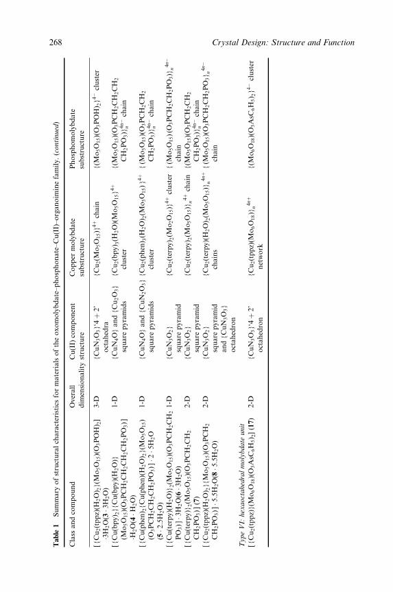
Table
1Sum
mary
ofst
ruct
ura
lch
ara
cter
istics
for
mate
rials
ofth
eoxom
oly
bdate
±phosp
honate
±C
u(I
I)±org
anoim
ine
fam
ily.(c
ontinued
)
Cla
ssand
com
pound
Over
all
dim
ensionality
Cu(I
I)co
mponen
t
stru
cture
Copper
moly
bdate
subst
ruct
ure
Phosp
hom
oly
bdate
subst
ruct
ure
[{C
u2(t
ppz)
(H2O
) 2}(M
o5O
15)(
O3PO
H) 2
]
�3H2O
(3�3
H2O
)
3-D
{C
uN
3O
3}`4�
2'
oct
ahed
ra
{C
u2(M
o5O
15)}
4�
chain
{(M
o5O
15)(
O3PO
H) 2
}4ÿ
clust
er
[{C
u(b
py) 2
}{C
u(b
py)(H
2O
)}
(Mo
5O
15)(
O3PC
H2C
H2C
H2C
H2PO
3)]
�H2O
(4�H
2O
)
1-D
{C
uN
4O
}and
{C
u2O
3}
square
pyra
mid
s
{C
u2(b
py) 3
(H2O
)(M
o5O
15}
4�
clust
er
{(M
o5O
15)(
O3PC
H2C
H2C
H2
CH
2PO
3)}
4nÿ
nch
ain
[{C
u(p
hen
) 2{C
u(p
hen
)(H
2O
) 2}(M
o5O
15)
(O3PC
H2C
H2C
H2PO
3)]�2�5
H2O
(5�2:5
H2O
)
1-D
{C
uN
4O
}and
{C
uN
2O
3}
square
pyra
mid
s
{C
u2(p
hen
) 3(H
2O
) 2(M
o5O
15)}
4�
clust
er
{(M
o5O
15)(
O3PC
H2C
H2
CH
2PO
3)}
4nÿ
nch
ain
[{C
u(t
erpy)(
H2O
)}2(M
o5O
15)(
O3PC
H2C
H2
PO
3)]�3
H2O
(6�3
H2O
)
1-D
{C
uN
3O
2}
square
pyra
mid
{C
u2(t
erpy) 2
(Mo
2O
15)}
4�
clust
er{(M
o5O
15)(O
3PC
H2C
H2PO
3)}
n4nÿ
chain
[{C
u(t
erpy)}
2(M
o5O
15)(
O3PC
H2C
H2
CH
2PO
3)](7
)
2-D
{C
uN
3O
2}
square
pyra
mid
{C
u2(t
erpy) 2
(Mo
5O
15)}
n4�
chain
{(M
o5O
15)(
O3PC
H2C
H2
CH
2PO
3)}
4nÿ
nch
ain
[{C
u2(t
ppz)
(H2O
) 2}{M
o5O
15)(
O3PC
H2
CH
2PO
3)]�5:5
H2O
(8�5:5
H2O
)
2-D
{C
uN
3O
2}
square
pyra
mid
and
{C
uN
3O
3}
oct
ahed
ron
{C
u2(t
erpy)(
H2O
) 2(M
o5O
15)}
n4n�
chain
s
{(M
o5O
15)(
O3PC
H2C
H2PO
3}
n4nÿ
chain
Type
VI:
hex
aoct
ahed
ralm
oly
bdate
unit
[{C
u2(t
ppz)
}(M
o6O
18)(
O3A
sC6H
5) 2
](1
7)
2-D
{C
uN
3O
3}`4�
2'
oct
ahed
ron
{C
u2(t
ppz)
(Mo
6O
18)}
n4n�
net
work
{(M
o6O
18)(
O3A
sC6H
5) 2
}4ÿ
clust
er
268 Crystal Design: Structure and Function
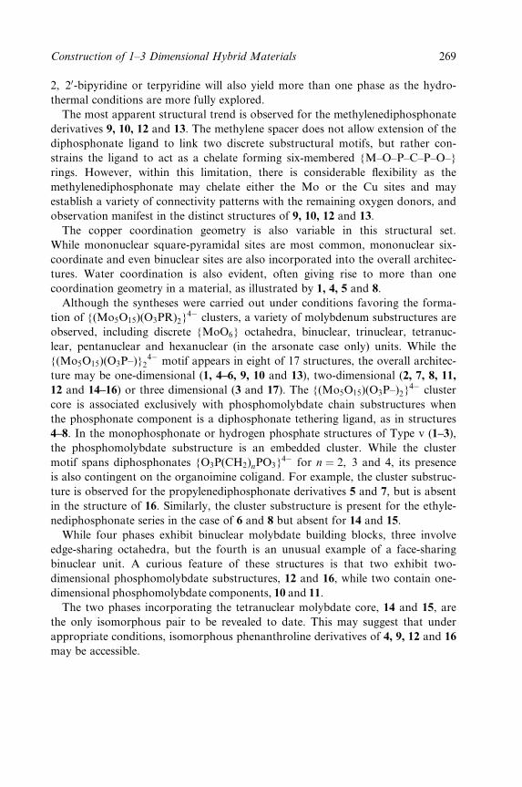
2, 20-bipyridine or terpyridine will also yield more than one phase as the hydro-
thermal conditions are more fully explored.
The most apparent structural trend is observed for the methylenediphosphonate
derivatives 9, 10, 12 and 13. The methylene spacer does not allow extension of the
diphosphonate ligand to link two discrete substructural motifs, but rather con-
strains the ligand to act as a chelate forming six-membered {M±O±P±C±P±O±}
rings. However, within this limitation, there is considerable ¯exibility as the
methylenediphosphonate may chelate either the Mo or the Cu sites and may
establish a variety of connectivity patterns with the remaining oxygen donors, and
observation manifest in the distinct structures of 9, 10, 12 and 13.
The copper coordination geometry is also variable in this structural set.
While mononuclear square-pyramidal sites are most common, mononuclear six-
coordinate and even binuclear sites are also incorporated into the overall architec-
tures. Water coordination is also evident, often giving rise to more than one
coordination geometry in a material, as illustrated by 1, 4, 5 and 8.
Although the syntheses were carried out under conditions favoring the forma-
tion of {(Mo5O15)(O3PR)2}4ÿ clusters, a variety of molybdenum substructures are
observed, including discrete {MoO6} octahedra, binuclear, trinuclear, tetranuc-
lear, pentanuclear and hexanuclear (in the arsonate case only) units. While the
{(Mo5O15)(O3P±)}24ÿ motif appears in eight of 17 structures, the overall architec-
ture may be one-dimensional (1, 4±6, 9, 10 and 13), two-dimensional (2, 7, 8, 11,
12 and 14±16) or three dimensional (3 and 17). The {(Mo5O15)(O3P±)2}4ÿ cluster
core is associated exclusively with phosphomolybdate chain substructures when
the phosphonate component is a diphosphonate tethering ligand, as in structures
4±8. In the monophosphonate or hydrogen phosphate structures of Type v (1±3),
the phosphomolybdate substructure is an embedded cluster. While the cluster
motif spans diphosphonates {O3P(CH2)nPO3}4ÿ for n � 2, 3 and 4, its presence
is also contingent on the organoimine coligand. For example, the cluster substruc-
ture is observed for the propylenediphosphonate derivatives 5 and 7, but is absent
in the structure of 16. Similarly, the cluster substructure is present for the ethyle-
nediphosphonate series in the case of 6 and 8 but absent for 14 and 15.
While four phases exhibit binuclear molybdate building blocks, three involve
edge-sharing octahedra, but the fourth is an unusual example of a face-sharing
binuclear unit. A curious feature of these structures is that two exhibit two-
dimensional phosphomolybdate substructures, 12 and 16, while two contain one-
dimensional phosphomolybdate components, 10 and 11.
The two phases incorporating the tetranuclear molybdate core, 14 and 15, are
the only isomorphous pair to be revealed to date. This may suggest that under
appropriate conditions, isomorphous phenanthroline derivatives of 4, 9, 12 and 16
may be accessible.
Construction of 1±3 Dimensional Hybrid Materials 269

5 CONCLUSIONS
A series of novel and complex structure types of the oxomolybdate±phosphonate±
Cu(II)±organoimine family have been isolated from hydrothermal media and
structurally characterized. The results reinforce the observation that hydrothermal
chemistry offers an effective synthetic tool for the isolation of composite organic±
inorganic materials. It is also clear that organic ligands with speci®c geometric
requirements may be introduced as structural components of materials. Bridging
ligands may be used to propagate the architecture about a metal site, while the
steric in¯uences of coligands to a secondary metal site may be exploited to dictate
the dimensionality of the product. Manipulation of the microstructure of the solid
is thus achieved by tuning the coordination in¯uences of the metal to the geomet-
ric requirements of the ligand.
It is noteworthy that the materials of this study require the presence of the
secondary metal±ligand coordination complex cation for isolation. This structural
component serves not only a space-®lling and charge-compensating role but is
also intimately involved in structural propagation in one or two dimensions.
While it is now evident that organic components may be introduced into the
synthesis solid-state inorganic materials in order to manipulate the coordination
chemistry of the metal and consequently the structure of the material, designed
extended structures remain elusive in the sense of predictability of the ®nal struc-
ture. However, this observation re¯ects the compositional and structural versatil-
ity of inorganic materials and should be considered an opportunity for
development rather than an occasion for lamentation. The subtle interplay of
metal oxidation states, coordination preferences, polyhedral variability, ligand
donor group types and orientations, spatial extension and steric constraints pro-
vides a limitless set of construction components for solid-state materials. As the
products of empirical observations are elucidated, the structure±function relation-
ships of such components will begin to emerge and to provide further guidelines
for synthetic methodologies.
ACKNOWLEDGMENT
This work was supported by a grant from the National Science Foundation
(CHE 9987471).
REFERENCES
1. Greenwood, N. N.; Earnshaw, A., Chemistry of the Elements. Pergamon Press, NewYork, 1984.
2. Wells, A. F., Structural Inorganic Chemistry, 4th edn. Oxford University Press, Oxford,1978.
270 Crystal Design: Structure and Function

3. Cheetham, A. J., Science 1994, 264, 794.4. Reynolds, T. G.; Buchanan, R. C., Ceramic Materials for Electronics, 2nd edn. Marcel
Dekker, New York, 1991, p. 207.5. BuÈchner, W., Schliebs, R.; Winter, G.; BuÈchel, K. H., Industrial Inorganic Chemistry.
VCH, New York, 1989.6. McCarroll, W. H., Encyclopedia of Inorganic Chemistry, Vol. 6. Wiley, New York,
1994, p. 2903.7. Haertling, G. H., Ceramic Materials for Electronics, 2nd edn. Marcel Dekker, New
York, 1991, p. 129.8. Leverenz, H. W., Luminescence of Solids. Wiley, New York, 1980.9. Einzinger, R., Annu. Rev. Mater. Sci. 1987, 17, 299.
10. Tarascon, J.-M.; Barboux, P.; Miceli, R. F.; Greene, L. H.; Hull, G. W.; Elbschutz, M.;Sunshine, S. A., Phys. Rev. B 1988, 37, 7458.
11. Matkin, D. I., Modern Oxide Materials. Academic Press, New York, 1972, p. 235.12. Rao, C. N. R.; Rao, K. J., in Solid State Chemistry: Compounds. Eds. A. K. Cheetham
and P. Day Clarendon Press, Oxford, 1992, p. 281.13. Bierlein, J. D.; Arweiler, C. B., Appl. Phys. Lett. 1987, 49, 917.14. Centi, G.; Trifuro, Ebner, J. R.; Franchett, V. M., Chem. Rev. 1988, 88, 55.15. Grasselli, R. K., Appl. Catal. 1985, 15, 127.16. Gasior, M.; Gasior, I.; Grzybowska, B., Appl. Catal. 1984, 15, 87.17. Okuhara, T.; Misono, M., Encyclopedia of Inorganic Chemistry, Vol. 6. Wiley, New
York, 1994, p. 2889.18. Niiyama, H.; Echigoya, E., Bull. Chem. Soc. Jpn. 1972, 45, 83.19. Yamaguchi, T., Appl. Catal. 1990, 61, 1.20. Clear®eld, A., Chem. Rev. 1988, 88, 125.21. Newsam, J. M., in Solid State Chemistry: Compounds. Eds. A. K. Cheetham and P. Day
Clarendon Press, Oxford, 1992, p. 234.22. Ruthven, D. M., Principles of Absorption and Absorption Processes. Wiley-Interscience,
New York, 1984.23. Szostak, R., Molecules Sieves. Principles of Synthesis and Identi®cation. Van Nostrand
Rheinhold, New York, 1988.24. Raleo, J. A., Zeolite Chemistry and Catalysis, ACS Monograph No. 7. American
Chemical Society, Washington, DC, 1976.25. Murakami, Y.; Iijima, A.; Ward, J. W. (Eds), New Developments in Zeolite Science.
Elsevier, Amsterdam, 1986.26. (a) Vaughan, D. E. W., Properties and Applications of Zeolites, Chemical Society
Special Publication No. 33. Chemical Society, London, 1979, p. 294; (b) Cheetham, A.K., Science 1994, 264, 794.
27. Venuto, P. B., Microporous Mater. 1994, 2, 297.28. Stupp, S. I.; Braun, P. V. Science 1997, 277, 1242.29. Whitesides, G. M.; Ismagilov, R. F. Science 1999, 284, 89.30. Hench, L. L., Inorganic Biomaterials, in Materials Chemistry, an Emerging Discipline,
ACS Symposium Series, Vol. 245, Interrante L. V.; Casper L. A.; Ellis, A.-B. (Eds).American Chemical Society, Washington, DC, 1995, p. 523; Mamm, S. J. Chem. Soc.,
Dalton Trans. 3953 (1997).31. Hagrman, P. J.; Hagrman, D.; Zubieta, J. Angew Chem., Int. Ed. Engl. 1999, 38, 2638.32. Yaghi, O. M.; Li, Hi., Davis, C., Richardson, D.; Gray, T. L. Acct. Chem. Res. 1998,
31, 474.33. Cheetham, A. K.; Fuay, G.; Loisean, T. Angew. Chem., Int. Ed. Engl. 1999, 38, 3268.34. (a) Raeo, J. A., Zeolite Chemistry and Catalysis, ACS Monograph No. 7. American
Chemical Society, Washington, DC, 1976; (b) Murakami, Y.; Iijima, A.; Ward, J. W.
AQ 1
AQ 2
AQ 3
AQ 4
Construction of 1±3 Dimensional Hybrid Materials 271
(Eds), New Development in Zeolite Science. Elsevier, Amsterdam, 1986; (c) Vaughan, D.E. W., Properties and Applications of Zeolites, Chemical Society Special PublicationNo. 33, Chemical Society, London, 1979, p. 294; (d) Venuto, P. B., Microporous Mater.1994, 2, 297; (e) Szostak, R., Molecular Sieve ± Principles of Synthesis and Identi®cation,2nd edn. Van Nostrand Rheinhold, New York, 1997.
35. (a) Smith, J. V., Chem. Rev. 1988, 88, 149; (b) Occelli, M. L.; Robson, H. C., Zeolite
Synthesis. American Chemical Society, Washington, DC, 1989.36. Barrer, R. M., Hydrothermal Chemistry of Zeolites. Academic Press, New York, 1982.37. Kresge, C. T., Leonowicz, M. E.; Roth, W. J.; Vartuli, J. C.; Beck, J. S., Nature 1992,
359, 710.38. The oxomolybdenum phosphates with entrained organic captions have been reviewed:
Haushalter, R. C.; Mundi, L. A., Chem. Mater. 1992, 4, 31.39. Khan, M. L.; Meyer, L. M.; Haushalter, R. C.; Schweitzer, C. L.; Zubieta, J.; Dye, J. L.,
Chem. Mater. 1996, 8, 43.40. Khan, M. I.; Haushalter, R. C.; O'Connor, C. J.; Tao, C.; Zubieta, J., Chem. Mater.
1995, 7, 593.41. Bircsak, Z.; Hall, A. K.; Harrison, W. T. A., J. Solid State Chem. 1999, 142, 168.42. Chippindale, A. M., Chem. Mater. 2000, 12, 818.43. Soghomonian, V.; Haushalter, R. C.; Chen, Q.; Zubieta, J., Inorg. Chem. 1994, 31, 25.44. Lu Y.; Haushalter, R. C.; Zubieta, J., Inorg. Chim. Acta 1997, 257, 268.45. Bircsak, Z.; Harrison, W. T. A., Inorg. Chem. 1998, 37, 3204.46. Finn, R. C.; Zubieta, J., unpublished results.47. Soghomonian, V.; Chen, Q.; Zhang, Y.; Haushalter, R. C.; O'Connor, C. J.; Tao, C.;
Zubieta, J., Inorg. Chem. 1995, 34, 3509.48. Soghomonian, V.; Chen, Q.; Haushalter, R. C.; Zubieta, J.; O'Connor, C. J.; Lee, Y.-S.,
Chem. Mater. 1993, 5, 1690.49. Loiseau, T.; FeÁrey, G., J. Solid State Chem. 1994, 111, 416.50. Soghomonian, V.; Chen, Q.; Haushalter, R. C.; Zubieta, J., Chem. Mater. 1996, 35, 2826.51. Soghomonian, V.; Chen, Q.; Haushalter, R. C.; Zubieta, J., O'Connor, C. J., Inorg.
Chem. 1996, 35, 2826.52. Bu, X.; Feng, P.; Stucky, G. D., Chem. Commun. 1995, 1337.53. Soghomonian, V.; Chen, Q.; Haushalter, R. C.; Zubieta, J., Angew. Chem., Int. Ed.
Engl. 1993, 32, 610.54. Harrison, W. T. A.; Hsu, K.; Jacobson, A. J., Chem. Mater. 1995, 7, 2004.55. Zhang, Y.; Clear®eld, A.; Haushalter, R. C., Chem. Mater. 1995, 7, 1221.56. Hagrman, P. J.; LaDuca, R. L. Jr; Koo, H.-J.; Rarig, R. S. Jr; Haushalter, R. C.;
Whangbo, M.-H.; Zubieta, J., Inorg. Chem. 2000, 39, 4311.57. Hagrman, P. J.; Zubieta, J., Inorg. Chem. 2000, 39, 3252.58. Zhang, Y.; DeBord, J. R. D.; O'Connor, C. J.; Haushalter, R. C.; Clear®eld, A.;
Zubieta, J., Angew. Chem., Int. Ed. Engl. 1996, 35, 989.59. Debord, J. R. D.; Zhang, Y.; Haushalter, R. C.; Zubieta, J.; O'Connor, C. J., Solid
State Chem. 1996, 122, 251.60. LaDuca, Jr., R. L.; Finn, R. C.; Zubieta, J., Chem. Commun. 1999, 1669.61. LaDuca, R. L. Jr; Rarig, R. S. Jr; Zubieta, J., Inorg. Chem. 2001, 40, 40.62. Ollivier, P. J.; DeBord, J. R. D.; Zapf, P. J.; Zubieta, J,; Meyer, L. M.; Wang, C.-C.;
Mallouk, T. E.; Haushalter, R. C., J. Mol. Struct. 1998, 470, 49.63. Hagrman, P. J.; Bridges, C.; Greedan, J. E.; Zubieta, J., J. Chem. Soc., Dalton Trans.
1999, 2901.64. LaDuca, Jr. R. C.; Brodkin, C.; Finn, R. C.; Zubieta, J., Inorg. Chem. Commun. 2000,
3, 248.
272 Crystal Design: Structure and Function
65. Hagrman, D.; Zubieta, C.; Haushalter, R. C.; Zubieta, J., Angew. Chem., Int. Ed. Engl.1999, 38, 2638.
66. Hagrman, D.; Zubieta, C.; Haushalter, R. C.; Zubieta, J., Angew. Chem., Int. Ed. Engl.1997, 36, 873.
67. Hagrman, D.; Zubieta, C.; Haushalter, R. C.; Zubieta, J., J. Chem. Soc., Dalton Trans.1999, 3707.
68. Hagrman, D.; Hagrman, P.; Zubieta, J., Inorg. Chim. Acta 2000, 300±302, 212.69. DeBord, J. R. D.; Haushalter, R. C.; Meyer, L. M.; Rose, D. J.; Zapf, P. J.; Zubieta,
J., Inorg. Chim. Acta 1997, 256, 165.70. Hagrman, D.; Zapf, P. J.; Zubieta, J., Chem. Commun. 1998, 1283.71. Hagrman, D.; Hagrman, P. J.; Zubieta, J., Angew. Chem., Int. Ed. Engl. 1999, 38, 3165.72. Hagrman, D.; Zubieta, J., C. R. Acad. Sci., Ser. IIc 2000, 3, 231.73. Hagrman, D.; Hagrman, P. J. Zubieta, J., Comments Inorg. Chem. 1999, 21, 225, and
references therein.74. Chesnut, D. J.; Hagrman, D.; Zapf, P. J.; Hammond, R. P.; LaDuca, Jr; Haushalter,
R. C.; Zubieta, J., Coord. Chem. Rev. 1999, 190±192, 737.75. Zapf, P. J.; Hammond, R. P.; Haushalter, R. C.; Zubieta, J., Chem. Mater. 1998, 10,
1366.76. Hagrman, D.; Warren, C. J.; Haushalter, R. C.; Seip, C.; O'Connor, C. J.; Rarig, R. S.
Jr.; Johnson, K. M. III; LaDuca, R. L. Jr; Zubieta, J., Chem. Mater. 1998, 10, 3294.77. Hagrman, D.; Haushalter, R. C.; Zubieta, J., Chem. Mater. 1998, 10, 361.78. Laskoski, M. C.; LaDuca, R. L. Jr; Rarig, R. S. Jr; Zubieta, J., J. Chem. Soc., Dalton,
Trans. 1999, 3467.79. Hagrman, D. E.; Zubieta, J., J. Solid State Chem. 2000, 152, 141.80. LaDuca, R. L. Jr.,; Desciak, M.; Laskoski, M.; Rarig, R. S.; Zubieta, J., J. Chem. Soc.,
Dalton Trans. 2000, 2255.81. Zapf, P. J.; Warren, C. J.; Haushalter, R. C.; Zubieta, J., Chem. Commun. 1997, 1543.82. Aschwanden, S.; Schmalle, H. W.; Reller, A.; Oswald, H.R., Mater. Res. Bull. 1993, 28,
45. For other examples of the V=O=M0 ligand family see also: (a) Lin, B.-Z .; Liu, S.-X.,Polyhedron 2000, 19, 2521; (b) Zheng, L.-M.; Zhao, J.-S.; Li, K.-H.; Zhang, L.-Y.;Liu, Y.; Xin, X.-Q., J. Chem. Soc., Dalton Trans. 1999, 939; (c) Chen, R.; Zavalij, P. Y.;Whittingham, M. S.; Greedan, J. E.; Raju, N. P.; Bieringer, M., J. Mater. Chem. 1999,93; (d) Shi, Z.; Zhang, L.; Zhu, G.; Yang, G.; Hua, J.; Ding, H.; Feng, S., Chem.
Mater. 1999, 11, 3565; (e) Law, T. S.-C.; Williams, I. D., Chem. Mater. 2000, 12, 2070;(f) Zheng. L.-M.; Whit®eld, T.; Wang, X.; Jacobson, A. J., Angew. Chem., Int. Ed.
Engl. 2000, 39, 4528.83. Pope, M. T., Heteropoly and Isopoly Oxometalates. Springer, New York, 1983.84. See, for example: (a) Hoskins, B. F.; Robson, R., J. Am. Chem. Soc. 1990, 112, 1546;
(b) Yaghi, O. M.; Li, H., J. Am. Chem. Soc. 1995, 117, 10401; (c) Carlucci, L.; Gian-franco, C.; Prosperio, D. M.; Sironi, A., J. Am. Chem. Soc. 1995, 117, 12861; (d)MacGillivray, L. R.; Subramanian, L. R.; Zaworotko, M. J., J. Chem. Soc. Chem.
Commun. 1994, 1325; (e) Blake, A. J.; Champness, N. R.; Chung, S. S. M.; Li, W.-S.;SchroÈder, M., Chem. Commun. 1997, 1005; (f) Noro, S.; Kitagawa, S.; Kondo, M.;Seki, K., Angew. Chem. Int. Ed. Engl. 2000, 39, 2082; (g) Carlucci, L.; Ciani, G.;Proserpio, D. M.; Rizzata, S., Chem. Commun. 2000, 1319; (h) Reineke, T. M.;Eddaoudi, M.; Moler, O'Keefe, M.; Yaghi, O. M., J. Am. Chem. Soc. 2000, 122, 4843.
85. See, for example: (a) Naumov, N. G.; Virovets, A. V.; Sokolov, M. N.; Artemkina, S.B.; Fedorov, V. E., Angew. Chem., Int. Ed. Engl. 1998, 37, 1943; (b) Beauvais, L. G.;Shores, M. P.; Long, J. R., J. Am. Chem. Soc. 1999, 121, 775; (d) MuÈller, A.; Das, S.K.; KoÈgerler, P.; BoÈgge, H.; Schmidtmann, M.; Trautwein, A. X.; SchuÈnemann, V.;
AQ 5
Construction of 1±3 Dimensional Hybrid Materials 273
85. Krickmeyer, E.; Preetz, W. Angew. Chem., Int. Ed. Engl. 2000, 39, 3414; (e) Khan, M.I.; Yohannes, E.; Powell, D., Inorg. Chem. 1999, 38, 212; (f) Ouahab, L., C. R. Acad.
Sci., Ser. IIc 1998, 369; (g) GalaÂn-MascaroÂs, J.; GimeÂnez-Saiz, C.; Triki, S.; GoÂmez-Garcia, C. J.; Coronado, E.; Quahab, L., Angew. Chem., Int. Ed. Engl. 1995, 34, 1460;(h) Sadakane, M.; Dickman, M. H.; Pope, M. T., Angew. Chem., Int. Ed. Engl. 2000,39, 2914; (i) Krebs, B.; Loose, I.; BoÈsing, M.; NoÈh, A.; Droste, E., C. R. Acad. Sci.,
Ser. IIc 1998, 351; (j) Stein, A.; Fendorf, M.; Jarvie, T. P.; Mueller, K. t.; Bensei, A.J.; Mallouk, T. E., Chem. Mater. 1995, 7, 304; (k) Holland, B. T.; Isbester, P. K.;Munson, E. J.; Stein, A., Mater. Res. Bull. 1999, 34, 471.
86. FeÂrey, G., J. Solid State Chem. 2000, 152, 37.87. Zaworotko, M. J., Angew. Chem., Int. Ed. Engl. 2000, 39, 3052.88. Kwak, W.; Pope, M. T.; Scully, T. F., J. Am. Chem. Soc. 1975, 97, 5735.89. Finn, R. C.; Zubieta, J., Inorg. Chem. 2000, 40, 2466.90. Figlarz, M., Chem. Scr. 1988, 28, 3.91. (a) Livage, J., Chem. Scr. 1988, 28, 9; (b) Rouxel, J. Chem. Scr. 1988, 28, 33.92. Khan, M.I.; Zubieta, J., Prog. Inorg. Chem. 1995, 43, 1.93. Gopalakrishnan, J., Chem. Mater. 1995, 7, 126594. Lobachev, A. N., Crystallization Processes Under Hydrothermal Conditions. Consult-
ants Bureau, New York, 1973.95. Rabenau, A., Angew. Chem., Int. Ed. Engl. 1985, 24, 1026.96. Feng, S.; Xu, R., Acc. Chem. Res. 2001, 34, 239.97. Hedman, B., Acta Chem. Scand. 1977, 27, 3335.98. Kwak, W.; Pope, M. T.; Scully, T. F., J. Am. Chem. Soc. 1975, 97, 5735.99. Chang, Y.-D., Zubieta, J., Inorg. Chim. Acta 1996, 248, 177.
100. Cao, G.; Haushalter, R. C.; Strohmaier, K. G., Inorg. Chem. 1993, 32, 127.101. Khan, M. I.; Chen, Q.; Zubeita, J., Inorg. Chim. Acta 1993, 206, 131.102. Poojary, D. M.; Zhang, Y.; Clear®eld, A., Chem. Mater. 1995, 7, 822.103. Harrison, W. T. A.; Dussack, L. L.; Jacobson, A., J. Inorg. Chem. 1995, 34, 4774.104. Lu, M.-Y.; Wang, S.-L., Chem. Mater. 1999, 11, 3588.105. Canadell, E.; Provost, J.; Guesder, A.; Borel, M. M.; Leclair, A., Chem. Mater. 1997,
9, 68.106. Kierkegaard, P., Acta Chem. Scand. 1958, 12, 1701; Weller, M. T.; Bell, R. G., Acta
Crystallogr. 1988, C44, 1516.107. Bonavia, G.; Haushalter, R. C.; O'Connor, C. J.; Zubieta, J., Inorg. Chem. 1996, 35,
5603.108. Soghomonian, V.; Chen, O.; Haushalter, R. C.; Zubieta, J., Angew. Chem., Int. Ed.
Engl. 1995, 34, 223.109. Huan, G.; Johnson, J. W.; Jacobson, A. J.; Merola, J. S., J. Solid State Chem. 1990,
89, 220.110. Hinclaus, C.; Serre, C.; Riou, D.; FeÂrey, G., C. R. Acad. Sci., Ser. IIc 1998, 1, 551.
AQ 6
AQ 7
AQ 8
274 Crystal Design: Structure and Function
Chapter 7
A Rational Approach for theSelf-Assembly of MolecularBuilding Blocks in the Field ofMolecule-Based Magnetism
MELANIE PILKINGTON AND SILVIO DECURTINS
University of Berne, Berne, Switzerland
1 INTRODUCTION
Although, historically, crystal engineering has its roots in the ®eld of solid-state
organic chemistry, in recent years it has developed into a hybrid discipline span-
ning many areas of chemistry with relevant interdisciplinary interactions with
biology, informatics and physics [1]. This expansion can largely be attributed to
the `marriage' of supramolecular chemistry with materials science. To date, the
®eld of crystal engineering draws its strength from the synergistic interaction
between the design and synthesis of supermolecules on the one hand, and the
design and synthesis of crystalline materials with desired solid-state properties on
the other. It has been recently pointed out [2] that the de®nition of supramolecu-
lar chemistry put forward by Jean-Marie Lehn [3], namely `chemistry beyond the
molecule bearing on the organised entities of higher complexity that result in the
association of two or more chemical species held together by intermolecular
forces', also encompasses crystal engineering, since one can describe a molecular
crystal as being an `organised entity of higher complexity held together by inter-
molecular forces'.
Crystal Design: Structure and Function. Volume 7Edited by Gautam R. Desiraju
Copyright 2003 John Wiley & Sons, Ltd.ISBN: 0-470-84333-0
During the last two decades, the ®eld of supramolecular chemistry has altered
the way in which chemists think about crystals. Instead of focusing on molecular
geometry, with a tendency perhaps to overlook the way in which the molecules
are arranged in three-dimensional space, the approach is now to think `supramo-
lecularly' with a higher hierarchy of a crystalline arrangement in mind. The need
for this new awareness `making crystals with a purpose' has perhaps been
most visible within the inorganic chemistry community, since it is in the area of
coordination chemistry that the directed synthesis of molecules for their packing
properties has been rede®ned within the ®eld of `supramolecular chemistry'
(Figure 1).
During recent years, a plethora of eloquent research has been conducted in
this discipline, resulting in an extensive array of helices, one-dimensional coordin-
ation polymers, two-dimensional grids and three-dimensional lattices [4,5].
The most common strategy is that of rational design, which utilises molecular
building blocks as nucleophilic spacers that have been encoded with the infor-
mation necessary to pre-determine the overall structure of the resulting product.
This strategy relies on the proper programming of angular and dimensional infor-
mation into both the electrophilic metals and the nucleophilic spacers [6]. In doing
so, the topology of the ensuing product can be controlled and/or directed. Crys-
tal-oriented strategies still closely resemble classical chemistry methods in the
sense that molecules are modelled, synthetic routes are devised and the products
are characterised and their physical properties investigated. Essentially, these pro-
cesses are repeated twice, in the ®rst instance to prepare the building blocks, and in
the second to arrange them in the desired way to obtain the desired physical
properties [2]. It is this second self-assembly process which has altered the way in
which chemists are thinking about chemistry. One advantage in favour of this
approach is that it is very often reversible, a factor that has been suggested to be
crucial for the assembly of ordered networks amenable to single-crystal diffraction
study. Furthermore, learning how to create large supramolecular units and the
elucidation of rules mediating their macroscopic organisation into multifunctional
materials offers fantastic prospects for the manipulation of not only the features
of speci®c molecules but also the bulk, intermolecular characteristics and proper-
ties of the entire crystalline aggregate.
Driving this ®eld forward are the potential technological applications associated
with molecule-based materials. As the limits of silicon are approached, the possi-
bility of `engineering up' from a molecule to a functioning electronic device offers
an alternative route to the design of materials for use on the nanoscale and
beyond [7]. The aim is to design and assemble molecular devices that will
reduce dimensions and increase speed by orders of magnitude. Chemists are
therefore targeting molecular systems that are easily switchable between two
available states. In this respect, molecular magnetism is a rapidly developing ®eld
since nanomagnetic materials in general easily reverse their magnetic moments in
a magnetic ®eld and are already widely used in information storage. Efforts in this
276 Crystal Design: Structure and Function
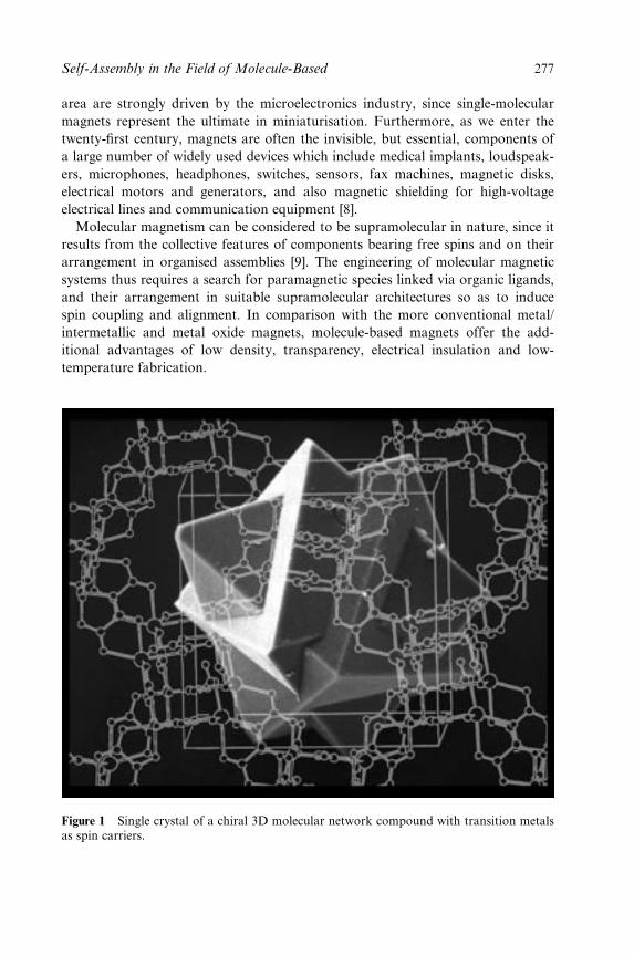
area are strongly driven by the microelectronics industry, since single-molecular
magnets represent the ultimate in miniaturisation. Furthermore, as we enter the
twenty-®rst century, magnets are often the invisible, but essential, components of
a large number of widely used devices which include medical implants, loudspeak-
ers, microphones, headphones, switches, sensors, fax machines, magnetic disks,
electrical motors and generators, and also magnetic shielding for high-voltage
electrical lines and communication equipment [8].
Molecular magnetism can be considered to be supramolecular in nature, since it
results from the collective features of components bearing free spins and on their
arrangement in organised assemblies [9]. The engineering of molecular magnetic
systems thus requires a search for paramagnetic species linked via organic ligands,
and their arrangement in suitable supramolecular architectures so as to induce
spin coupling and alignment. In comparison with the more conventional metal/
intermetallic and metal oxide magnets, molecule-based magnets offer the add-
itional advantages of low density, transparency, electrical insulation and low-
temperature fabrication.
Figure 1 Single crystal of a chiral 3D molecular network compound with transition metalsas spin carriers.
Self-Assembly in the Field of Molecule-Based 277
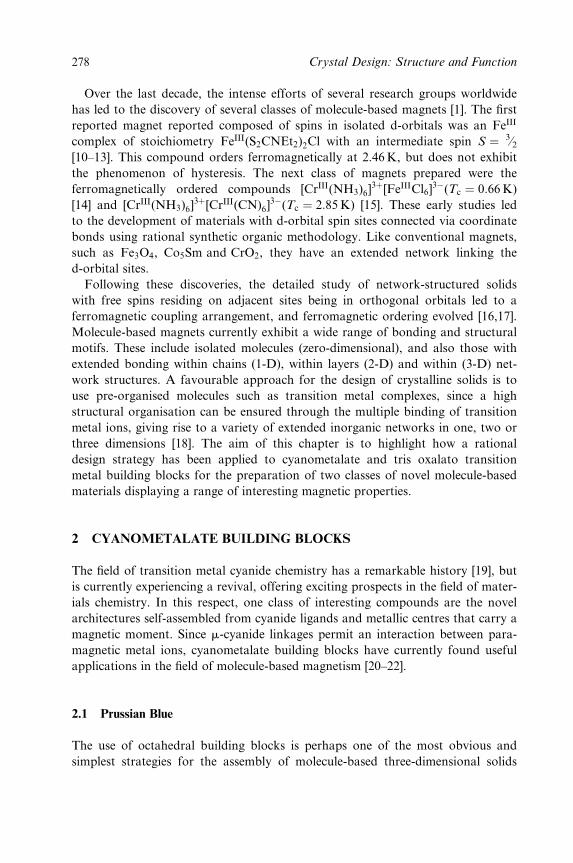
Over the last decade, the intense efforts of several research groups worldwide
has led to the discovery of several classes of molecule-based magnets [1]. The ®rst
reported magnet reported composed of spins in isolated d-orbitals was an FeIII
complex of stoichiometry FeIII(S2CNEt2)2Cl with an intermediate spin S � 3¤2[10±13]. This compound orders ferromagnetically at 2.46K, but does not exhibit
the phenomenon of hysteresis. The next class of magnets prepared were the
ferromagnetically ordered compounds [CrIII(NH3)6]3�[FeIIICl6]
3ÿ(Tc � 0:66 K)
[14] and [CrIII(NH3)6]3�[CrIII(CN)6]
3ÿ(Tc � 2:85 K) [15]. These early studies led
to the development of materials with d-orbital spin sites connected via coordinate
bonds using rational synthetic organic methodology. Like conventional magnets,
such as Fe3O4, Co5Sm and CrO2, they have an extended network linking the
d-orbital sites.
Following these discoveries, the detailed study of network-structured solids
with free spins residing on adjacent sites being in orthogonal orbitals led to a
ferromagnetic coupling arrangement, and ferromagnetic ordering evolved [16,17].
Molecule-based magnets currently exhibit a wide range of bonding and structural
motifs. These include isolated molecules (zero-dimensional), and also those with
extended bonding within chains (1-D), within layers (2-D) and within (3-D) net-
work structures. A favourable approach for the design of crystalline solids is to
use pre-organised molecules such as transition metal complexes, since a high
structural organisation can be ensured through the multiple binding of transition
metal ions, giving rise to a variety of extended inorganic networks in one, two or
three dimensions [18]. The aim of this chapter is to highlight how a rational
design strategy has been applied to cyanometalate and tris oxalato transition
metal building blocks for the preparation of two classes of novel molecule-based
materials displaying a range of interesting magnetic properties.
2 CYANOMETALATE BUILDING BLOCKS
The ®eld of transition metal cyanide chemistry has a remarkable history [19], but
is currently experiencing a revival, offering exciting prospects in the ®eld of mater-
ials chemistry. In this respect, one class of interesting compounds are the novel
architectures self-assembled from cyanide ligands and metallic centres that carry a
magnetic moment. Since m-cyanide linkages permit an interaction between para-
magnetic metal ions, cyanometalate building blocks have currently found useful
applications in the ®eld of molecule-based magnetism [20±22].
2.1 Prussian Blue
The use of octahedral building blocks is perhaps one of the most obvious and
simplest strategies for the assembly of molecule-based three-dimensional solids
278 Crystal Design: Structure and Function
[20,21]. In this context, an examination of suitable octahedral [ML6] precursors
reveals that some of the most inert are the hexacyanometalate anions
[M0(III)(CN)6]3ÿ(M0 � Cr, Mn, Fe, Co), which can be combined with paramag-
netic divalent Lewis acids M(II)(M � Cu, Ni, Co, Fe, Mn) to give face-centred
cubic compounds closely related to Prussian blue. Prussian blue is one of the
®rst synthetic coordination compounds reported in the chemical literature [23],
and owes its name to its colour, since mixing together an aqueous solution of
K4[Fe(CN)6] and Fe(III) chloride affords a beautiful deep-blue colour. The for-
mula of Prussian blue itself is FeIII4 [FeII(CN)6]3 � 14H2O and the reaction leading
to the neutral solid is a simple Lewis acid±base interaction:
q[FeII(CN)6]pÿ(aq)(Lewis base)� pMIIIq�
(aq)(Lewis acid)ÿ! {FeIIIp[M
II(CN)6]q}0 � xH2O(solid)
The structure of Prussian blue was ®rst proposed by Keggin and Miles [24], in
1936 and then reformulated by Ludi and GuÈdel [25] in 1973. Essentially, the face-
centred cubic structure of the earlier model postulating the occurrence of intersti-
tial Fe(III) ions was modi®ed to a cubic lattice with a random to more ordered
arrangement of a stoichiometrically determined fraction of vacant lattice sites.
Applying the revised structural model to Prussian blue, it becomes apparent that
due to coordinated water molecules, the Fe(III) ions are in an average N4:5O1:5
coordination environment. A recent search of the Cambridge Crystallographic
Structural Database revealed that to date there is only one single-crystal structure
of a `perfectly ordered' cubic Prussian blue-like phase (Figure 2). This compound
is a Cd/Pd analogue of stoichiometry [Cd(II)Pd(IV)(CN)6] [26] and does not con-
tain any vacant metal sites or coordinated water molecules. It should be stressed,
however, that these crystals are colourless and diamagnetic and so are not useful
for magnetostructural correlations.
The appeal of Prussian Blue itself lies not only in its optical properties,
but also in its magnetic properties, since it displays long-range ferromagnetic
ordering at Tc � 5:6K. This critical temperature is low since only the high-spin
d5 Fe(III) (S � 5=2) sites carry a spin. As for the Fe(II) centres, they are low spin
and diamagnetic, hence the magnetic interactions occur between next-nearest
metal ions through 10.6AÊ long Fe(III)±NC±Fe(II)±CN±Fe(III) linkages [7]. This
propagation of magnetic interactions through extended bridging networks is due
to the strong spin delocalisation from the metal ion towards its nearest neigh-
bours, and seems to be speci®c to molecular compounds. In recent years, the
Prussian blue system has been re-investigated with a view to engineering molecu-
lar solids with orbital interactions in three dimensions, in an attempt to overcome
the low Curie temperatures which plagued the low-dimensional materials around
at the time [27]. As a consequence, substitution of FeII and FeIII by other para-
magnetic metal ions M and M0 has afforded a series of Prussian blue analogues
with face-centred cubic structural topologies and interesting magnetic properties
[1,20,21].
Self-Assembly in the Field of Molecule-Based 279
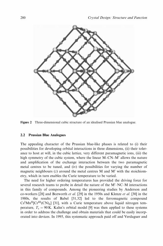
Figure 2 Three-dimensional cubic structure of an idealised Prussian blue analogue.
2.2 Prussian Blue Analogues
The appealing character of the Prussian blue-like phases is related to (i) their
possibilities for developing orbital interactions in three dimensions, (ii) their toler-
ance to host at will, in the cubic lattice, very different paramagnetic ions, (iii) the
high symmetry of the cubic system, where the linear M±CN±M0 allows the nature
and ampli®cation of the exchange interaction between the two paramagnetic
metal centres to be tuned, and (iv) the possibilities for varying the number of
magnetic neighbours (z) around the metal centres M and M0 with the stoichiom-
etry, which in turn enables the Curie temperature to be varied.
The need for higher ordering temperatures has provided the driving force for
several research teams to probe in detail the nature of the M0±NC±M interactions
in this family of compounds. Among the pioneering studies by Anderson and
co-workers [28] and Bozworth et al. [29] in the 1950s and Klenze et al. [30] in the
1980s, the results of Babel [31,32] led to the ferromagnetic compound
CsIMnII[CrIII(CN)6] [31], with a Curie temperature above liquid nitrogen tem-
perature, Tc � 90K. Kahn's orbital model [9] was then applied to these systems
in order to address the challenge and obtain materials that could be easily incorp-
orated into devices. In 1995, this systematic approach paid off and Verdaguer and
280 Crystal Design: Structure and Function
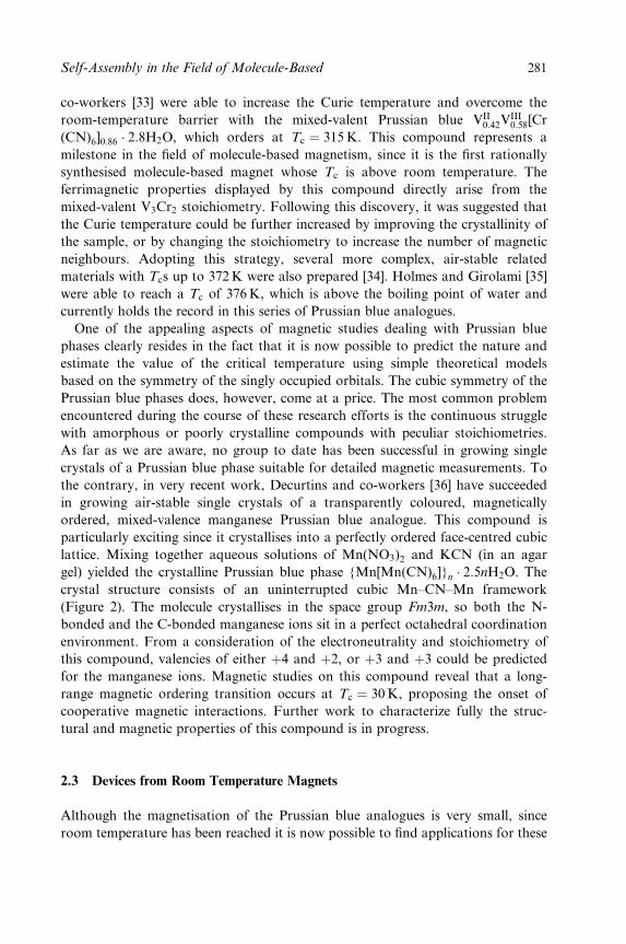
co-workers [33] were able to increase the Curie temperature and overcome the
room-temperature barrier with the mixed-valent Prussian blue VII0:42V
III0:58[Cr
(CN)6]0:86 � 2:8H2O, which orders at Tc � 315 K. This compound represents a
milestone in the ®eld of molecule-based magnetism, since it is the ®rst rationally
synthesised molecule-based magnet whose Tc is above room temperature. The
ferrimagnetic properties displayed by this compound directly arise from the
mixed-valent V3Cr2 stoichiometry. Following this discovery, it was suggested that
the Curie temperature could be further increased by improving the crystallinity of
the sample, or by changing the stoichiometry to increase the number of magnetic
neighbours. Adopting this strategy, several more complex, air-stable related
materials with Tcs up to 372K were also prepared [34]. Holmes and Girolami [35]
were able to reach a Tc of 376K, which is above the boiling point of water and
currently holds the record in this series of Prussian blue analogues.
One of the appealing aspects of magnetic studies dealing with Prussian blue
phases clearly resides in the fact that it is now possible to predict the nature and
estimate the value of the critical temperature using simple theoretical models
based on the symmetry of the singly occupied orbitals. The cubic symmetry of the
Prussian blue phases does, however, come at a price. The most common problem
encountered during the course of these research efforts is the continuous struggle
with amorphous or poorly crystalline compounds with peculiar stoichiometries.
As far as we are aware, no group to date has been successful in growing single
crystals of a Prussian blue phase suitable for detailed magnetic measurements. To
the contrary, in very recent work, Decurtins and co-workers [36] have succeeded
in growing air-stable single crystals of a transparently coloured, magnetically
ordered, mixed-valence manganese Prussian blue analogue. This compound is
particularly exciting since it crystallises into a perfectly ordered face-centred cubic
lattice. Mixing together aqueous solutions of Mn(NO3)2 and KCN (in an agar
gel) yielded the crystalline Prussian blue phase {Mn[Mn(CN)6]}n � 2:5nH2O. The
crystal structure consists of an uninterrupted cubic Mn±CN±Mn framework
(Figure 2). The molecule crystallises in the space group Fm3m, so both the N-
bonded and the C-bonded manganese ions sit in a perfect octahedral coordination
environment. From a consideration of the electroneutrality and stoichiometry of
this compound, valencies of either �4 and �2, or �3 and �3 could be predicted
for the manganese ions. Magnetic studies on this compound reveal that a long-
range magnetic ordering transition occurs at Tc � 30 K, proposing the onset of
cooperative magnetic interactions. Further work to characterize fully the struc-
tural and magnetic properties of this compound is in progress.
2.3 Devices from Room Temperature Magnets
Although the magnetisation of the Prussian blue analogues is very small, since
room temperature has been reached it is now possible to ®nd applications for these
Self-Assembly in the Field of Molecule-Based 281
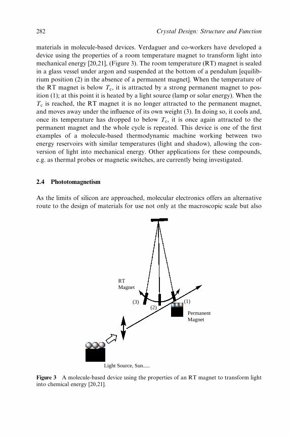
materials in molecule-based devices. Verdaguer and co-workers have developed a
device using the properties of a room temperature magnet to transform light into
mechanical energy [20,21], (Figure 3). The room temperature (RT) magnet is sealed
in a glass vessel under argon and suspended at the bottom of a pendulum [equilib-
rium position (2) in the absence of a permanent magnet]. When the temperature of
the RT magnet is below Tc, it is attracted by a strong permanent magnet to pos-
ition (1); at this point it is heated by a light source (lamp or solar energy). When the
Tc is reached, the RT magnet it is no longer attracted to the permanent magnet,
and moves away under the in¯uence of its own weight (3). In doing so, it cools and,
once its temperature has dropped to below Tc, it is once again attracted to the
permanent magnet and the whole cycle is repeated. This device is one of the ®rst
examples of a molecule-based thermodynamic machine working between two
energy reservoirs with similar temperatures (light and shadow), allowing the con-
version of light into mechanical energy. Other applications for these compounds,
e.g. as thermal probes or magnetic switches, are currently being investigated.
2.4 Phototomagnetism
As the limits of silicon are approached, molecular electronics offers an alternative
route to the design of materials for use not only at the macroscopic scale but also
RTMagnet
(3)(2)
(1)
PermanentMagnet
Light Source, Sun.....
Figure 3 A molecule-based device using the properties of an RT magnet to transform lightinto chemical energy [20,21].
282 Crystal Design: Structure and Function
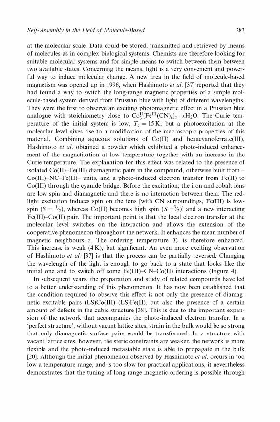
at the molecular scale. Data could be stored, transmitted and retrieved by means
of molecules as in complex biological systems. Chemists are therefore looking for
suitable molecular systems and for simple means to switch between them between
two available states. Concerning the means, light is a very convenient and power-
ful way to induce molecular change. A new area in the ®eld of molecule-based
magnetism was opened up in 1996, when Hashimoto et al. [37] reported that they
had found a way to switch the long-range magnetic properties of a simple mol-
ecule-based system derived from Prussian blue with light of different wavelengths.
They were the ®rst to observe an exciting photomagnetic effect in a Prussian blue
analogue with stoichiometry close to CoII3 [FeIII(CN)6]2 � xH2O. The Curie tem-
perature of the initial system is low, Tc � 15 K, but a photoexcitation at the
molecular level gives rise to a modi®cation of the macroscopic properties of this
material. Combining aqueous solutions of Co(II) and hexacyanoferrate(III),
Hashimoto et al. obtained a powder which exhibited a photo-induced enhance-
ment of the magnetisation at low temperature together with an increase in the
Curie temperature. The explanation for this effect was related to the presence of
isolated Co(II)±Fe(III) diamagnetic pairs in the compound, otherwise built from ±
Co(III)±NC±Fe(II)± units, and a photo-induced electron transfer from Fe(II) to
Co(III) through the cyanide bridge. Before the excitation, the iron and cobalt ions
are low spin and diamagnetic and there is no interaction between them. The red-
light excitation induces spin on the ions [with CN surroundings, Fe(III) is low-
spin (S � 1¤2), whereas Co(II) becomes high spin (S �3¤2)] and a new interacting
Fe(III)±Co(II) pair. The important point is that the local electron transfer at the
molecular level switches on the interaction and allows the extension of the
cooperative phenomenon throughout the network. It enhances the mean number of
magnetic neighbours z. The ordering temperature Tc is therefore enhanced.
This increase is weak (4 K), but signi®cant. An even more exciting observation
of Hashimoto et al. [37] is that the process can be partially reversed. Changing
the wavelength of the light is enough to go back to a state that looks like the
initial one and to switch off some Fe(III)±CN±Co(II) interactions (Figure 4).
In subsequent years, the preparation and study of related compounds have led
to a better understanding of this phenomenon. It has now been established that
the condition required to observe this effect is not only the presence of diamag-
netic excitable pairs (LS)Co(III)±(LS)Fe(II), but also the presence of a certain
amount of defects in the cubic structure [38]. This is due to the important expan-
sion of the network that accompanies the photo-induced electron transfer. In a
`perfect structure', without vacant lattice sites, strain in the bulk would be so strong
that only diamagnetic surface pairs would be transformed. In a structure with
vacant lattice sites, however, the steric constraints are weaker, the network is more
¯exible and the photo-induced metastable state is able to propagate in the bulk
[20]. Although the initial phenomenon observed by Hashimoto et al. occurs in too
low a temperature range, and is too slow for practical applications, it nevertheless
demonstrates that the tuning of long-range magnetic ordering is possible through
Self-Assembly in the Field of Molecule-Based 283
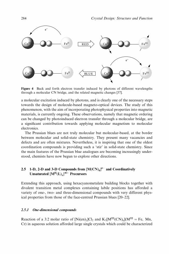
CoIII FeII CoII FeIII
CoII FeIIICoIII FeII
e−
e−
BLUE
RED
Figure 4 Back and forth electron transfer induced by photons of different wavelengthsthrough a molecular CN bridge, and the related magnetic changes [37].
a molecular excitation induced by photons, and is clearly one of the necessary steps
towards the design of molecule-based magneto-optical devices. The study of this
phenomenon, with the aim of incorporating photophysical properties into magnetic
materials, is currently ongoing. These observations, namely that magnetic ordering
can be changed by photoinduced electron transfer through a molecular bridge, are
a signi®cant contribution towards applying molecular magnetism to molecular
electronics.
The Prussian blues are not truly molecular but molecular-based, at the border
between molecular and solid-state chemistry. They present many vacancies and
defects and are often mixtures. Nevertheless, it is inspiring that one of the oldest
coordination compounds is providing such a `stir' in solid-state chemistry. Since
the main features of the Prussian blue analogues are becoming increasingly under-
stood, chemists have now begun to explore other directions.
2.5 1-D, 2-D and 3-D Compounds from [M(CN)6]nÿ and Coordinatively
Unsaturated [MII(L)x]m� Precursors
Extending this approach, using hexacyanometalate building blocks together with
divalent transition metal complexes containing labile positions has afforded a
variety of one-, two- and three-dimensional compounds with very different phys-
ical properties from those of the face-centred Prussian blues [20±22].
2.5.1 One-dimensional compounds
Reaction of a 3:2 molar ratio of [Ni(en)3]Cl2 and K3[MIII(CN)6](M
III � Fe, Mn,
Cr) in aqueous solution afforded large single crystals which could be characterized
284 Crystal Design: Structure and Function
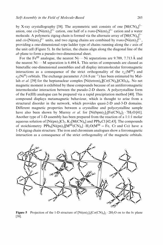
by X-ray crystallography [38]. The asymmetric unit consists of one [M(CN)6]3ÿ
anion, one cis-[Ni(en)2]2� cation, one half of a trans-[Ni(en)2]
2� cation and a water
molecule. A polymeric zigzag chain is formed via the alternate array of [M(CN)6]3ÿ
and cis-[Ni(en)2]2� units, and two zigzag chains are combined by trans-[Ni(en)2]
2�,providing a one-dimensional rope ladder type of chains running along the c axis of
the unit cell (Figure 5). In the lattice, the chains align along the diagonal line of the
ab plane to form a pseudo-two-dimensional sheet.
For the FeIII analogue, the nearest Ni � � �Ni separations are 9.709, 7.713 AÊ and
the nearest Ni � � �M separation is 6.494 AÊ . This series of compounds are classed as
bimetallic one-dimensional assemblies and all display intramolecular ferromagnetic
interactions as a consequence of the strict orthogonality of the t2g(MIII) and
eg(NiII) orbitals. The exchange parameter J (16:8 cmÿ1) has been estimated by Mal-
lah et al. [39] for the heptanuclear complex [Ni(tetren)6][Cr(CN)6](ClO4)9. No net
magnetic moment is exhibited by these compounds because of an antiferromagnetic
intermolecular interaction between the pseudo-2-D sheets. A polycrystalline form
of the Fe(III) analogue can be prepared via a rapid precipitation method [40]. This
compound displays metamagnetic behaviour, which is thought to arise from a
structural disorder in the network, which provides quasi-2-D and-3-D domains.
Different magnetic properties between a crystalline and polycrystalline sample
have also been shown by Murrey et al. for [Ni(bpm)2]2[Fe(CN)6]2 � 7H2O [41].
Another type of 1-D assembly has been prepared from the reaction of a 1:1:1 molar
aqueous solution of [Ni(pn)3]Cl2, K3[M(CN)6] and PPh4Cl [42,43]. The compounds
of stoichiometry PPh4[Ni(pn)2][MIII(CN)6] �H2O(MIII � Fe, Cr and Co) have a
1-D zigzag chain structure. The iron and chromium analogues show a ferromagnetic
interaction as a consequence of the strict orthogonality of the magnetic orbitals.
Figure 5 Projection of the 1-D structure of [Ni(en)2]3[Co(CN)6]2 � 2H2O on to the bc plane[38].
Self-Assembly in the Field of Molecule-Based 285
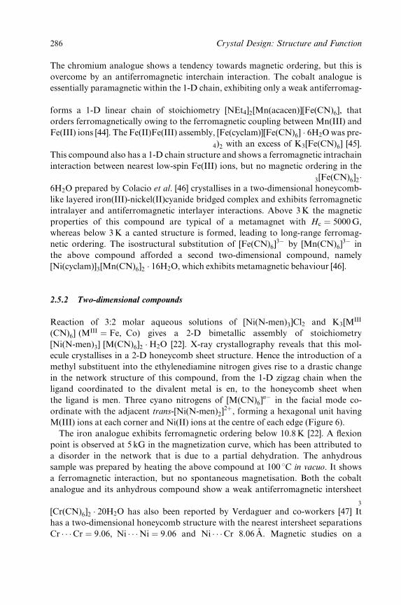
The chromium analogue shows a tendency towards magnetic ordering, but this is
overcome by an antiferromagnetic interchain interaction. The cobalt analogue is
essentially paramagnetic within the 1-D chain, exhibiting only a weak antiferromag-
netic interchain interaction. The use of [Mn(acacen)Cl] as the cationic constituent
forms a 1-D linear chain of stoichiometry [NEt4]2[Mn(acacen)][Fe(CN)6], that
orders ferromagnetically owing to the ferromagnetic coupling between Mn(III) and
Fe(III) ions [44]. The Fe(II)Fe(III) assembly, [Fe(cyclam)][Fe(CN)6] � 6H2O was pre-
pared via the reaction of [Ni(cyclam)](ClO4)2 with an excess of K3[Fe(CN)6] [45].
This compound also has a 1-D chain structure and shows a ferromagnetic intrachain
interaction between nearest low-spin Fe(III) ions, but no magnetic ordering in the
bulk. In contrast, the Ni(II) analogue of stoichiometry [Ni(cyclam)]3[Fe(CN)6]2�6H2O prepared by Colacio et al. [46] crystallises in a two-dimensional honeycomb-
like layered iron(III)-nickel(II)cyanide bridged complex and exhibits ferromagnetic
intralayer and antiferromagnetic interlayer interactions. Above 3K the magnetic
properties of this compound are typical of a metamagnet with Hc � 5000G,
whereas below 3K a canted structure is formed, leading to long-range ferromag-
netic ordering. The isostructural substitution of [Fe(CN)6]3ÿ by [Mn(CN)6]
3ÿ in
the above compound afforded a second two-dimensional compound, namely
[Ni(cyclam)]3[Mn(CN)6]2 � 16H2O, which exhibits metamagnetic behaviour [46].
2.5.2 Two-dimensional compounds
Reaction of 3:2 molar aqueous solutions of [Ni(N-men)3]Cl2 and K3[MIII
(CN)6] (MIII � Fe, Co) gives a 2-D bimetallic assembly of stoichiometry
[Ni(N-men)3] [M(CN)6]2 �H2O [22]. X-ray crystallography reveals that this mol-
ecule crystallises in a 2-D honeycomb sheet structure. Hence the introduction of a
methyl substituent into the ethylenediamine nitrogen gives rise to a drastic change
in the network structure of this compound, from the 1-D zigzag chain when the
ligand coordinated to the divalent metal is en, to the honeycomb sheet when
the ligand is men. Three cyano nitrogens of [M(CN)6]nÿ in the facial mode co-
ordinate with the adjacent trans-[Ni(N-men)2]2�, forming a hexagonal unit having
M(III) ions at each corner and Ni(II) ions at the centre of each edge (Figure 6).
The iron analogue exhibits ferromagnetic ordering below 10.8K [22]. A ¯exion
point is observed at 5 kG in the magnetization curve, which has been attributed to
a disorder in the network that is due to a partial dehydration. The anhydrous
sample was prepared by heating the above compound at 100 8C in vacuo. It shows
a ferromagnetic interaction, but no spontaneous magnetisation. Both the cobalt
analogue and its anhydrous compound show a weak antiferromagnetic intersheet
interaction. A related two-dimensional compound of stoichiometry [Ni(cyclam)]3[Cr(CN)6]2 � 20H2O has also been reported by Verdaguer and co-workers [47] It
has a two-dimensional honeycomb structure with the nearest intersheet separations
Cr � � �Cr � 9:06, Ni � � �Ni � 9:06 and Ni � � �Cr 8.06AÊ . Magnetic studies on a
286 Crystal Design: Structure and Function
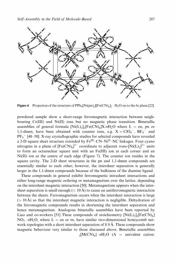
Figure 6 Projection of the structure of PPh4[Ni(pn)2][Fe(CN)6]2 �H2O on to the bc plane [22].
powdered sample show a short-range ferromagnetic interaction between neigh-
bouring Cr(III) and Ni(II) ions but no magnetic phase transition. Bimetallic
assemblies of general formula [Ni(L)2]2[Fe(CN)6]X�nH2O where L � en, pn or
1,1-dmen, have been obtained with counter ions, e.g. X � ClO4ÿ, BF4
ÿ and
PF6ÿ [48±50]. X-ray crystallographic studies for selected compounds have revealed
a 2-D square sheet structure extended by FeIII±CN±NiII±NC linkages. Four cyano
nitrogens in a plane of [Fe(CN)6]3ÿ coordinate to adjacent trans-[Ni(L)2]
2� units
to form an octanuclear square unit with an Fe(III) ion at each corner and an
Ni(II) ion at the centre of each edge (Figure 7). The counter ion resides in the
square cavity. The 2-D sheet structures in the pn and 1,1-dmen compounds are
essentially similar to each other; however, the intersheet separation is generally
larger in the 1,1-dmen compounds because of the bulkiness of the diamine ligand.
These compounds in general exhibit ferromagnetic intrasheet interactions and
either long-range magnetic ordering or metamagnetism over the lattice, depending
on the intersheet magnetic interaction [50]. Metamagnetism appears when the inter-
sheet separation is small enough (< 10 AÊ ) to cause an antiferromagnetic interaction
between the sheets. Ferromagnetism occurs when the intersheet interaction is large
(> 10AÊ ) so that the intersheet magnetic interaction is negligible. Dehydration of
the ferromagnetic compounds results in shortening the intersheet separation and
hence metamagnetism. Analogous bimetallic assemblies have been reported by
Liao and co-workers [51] These compounds of stoichiometry [Ni(L)2]2[Fe(CN)6]
NO3 � nH2O, where L � en or tn, have similar two-dimensional honeycomb net-
work topologies with a short intersheet separation of 8.9 AÊ . These compounds show
magnetic behaviour very similar to those discussed above. Bimetallic assemblies
of the general formula A[Mn(L)]2[M(CN)6] � nH2O (A � univalent cation:
AQ1
Self-Assembly in the Field of Molecule-Based 287
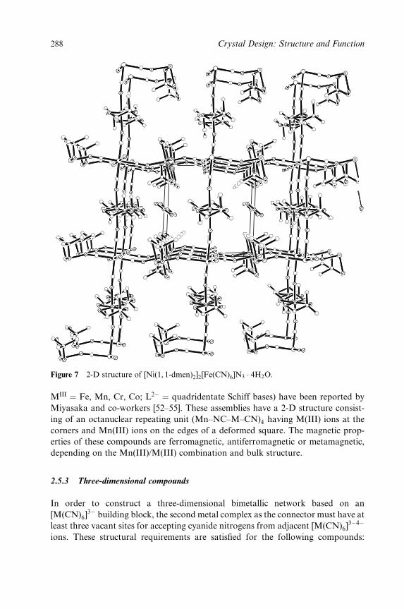
Figure 7 2-D structure of [Ni(1, 1-dmen)2]2[Fe(CN)6]N3 � 4H2O.
MIII � Fe, Mn, Cr, Co; L2ÿ � quadridentate Schiff bases) have been reported by
Miyasaka and co-workers [52±55]. These assemblies have a 2-D structure consist-
ing of an octanuclear repeating unit (Mn±NC±M±CN)4 having M(III) ions at the
corners and Mn(III) ions on the edges of a deformed square. The magnetic prop-
erties of these compounds are ferromagnetic, antiferromagnetic or metamagnetic,
depending on the Mn(III)/M(III) combination and bulk structure.
2.5.3 Three-dimensional compounds
In order to construct a three-dimensional bimetallic network based on an
[M(CN)6]3ÿ building block, the second metal complex as the connector must have at
least three vacant sites for accepting cyanide nitrogens from adjacent [M(CN)6]3ÿ4ÿ
ions. These structural requirements are satis®ed for the following compounds:
288 Crystal Design: Structure and Function
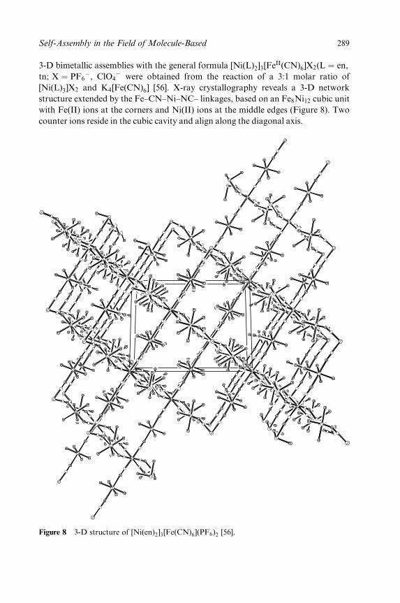
3-D bimetallic assemblies with the general formula [Ni(L)2]3[FeII(CN)6]X2(L � en,
tn; X � PF6ÿ, ClO4
ÿ were obtained from the reaction of a 3:1 molar ratio of
[Ni(L)3]X2 and K4[Fe(CN)6] [56]. X-ray crystallography reveals a 3-D network
structure extended by the Fe±CN±Ni±NC± linkages, based on an Fe8Ni12 cubic unit
with Fe(II) ions at the corners and Ni(II) ions at the middle edges (Figure 8). Two
counter ions reside in the cubic cavity and align along the diagonal axis.
Figure 8 3-D structure of [Ni(en)2]3[Fe(CN)6](PF6)2 [56].
Self-Assembly in the Field of Molecule-Based 289

Magnetic studies reveal a ferromagnetic exchange interaction between nearest
Ni(II) ions through the diamagnetic Fe(II) ion. No magnetic ordering occurs over
the lattice down to 2K owing to the diamagnetic nature of [FeII(CN)6]4ÿ. In 1996,
Gatteschi and co-workers [57] reported a 3-D bimetallic assembly of formula
[Ni(tren)]3[Fe(CN)6] � 6H2O that crystallises in a complicated 3-D network and
orders ferrimagnetically at 8K. Structural strain causes a weak antiferromagntic
interaction between the Fe(III) and Ni(II) ions on intersections of 1-D chains.
A 3-D magnetic lattice then arises from the antiferromagnetically coupled 1-D -
ferromagnetic chains. A 3-D assembly of stoichiometry [Mn(en)]3[Cr(CN)6]2 � 4H2O
was obtained by Ohba et al. [58]. Characterization by X-ray crystallography reveals
that a 3-D network is formed by an alternate array of [Cr(CN)6]3ÿ and [Mn(en)]2�
ions. The structure is based on a defective cubane with three Cr atoms and four Mn
atoms at the corners of the cube and eight Cr±CN±Mn edges. This compound
exhibits a ferromagnetic ordering at 69 K based on a short-range antiferromagnetic
interaction between Mn(II) and Cr(III) ions. The magnetic hysteresis loop at 2K is
typical of soft magnets showing a weak coercive ®eld Hc � 28 G. This compound
can be compared with a Prussian blue-like phase where the M(H2O)2]2� is simply
replaced by [M(en)]2�. This strategy has recently been extended by Okawa and
co-workers [59] to prepare two cyanide-bridged 3-D bimetallic ferrimagnets of the
type [Mn(L)]3[Cr(CN)6]2 � nH2O, where L � ethylenediamine, n � 4, or L � glycine
amide, n � 2:5. Once again X-ray crystallographic studies show that these com-
pounds have a 3-D network structure based on a defective cubane unit. Magnetic
studies demonstrate that both compounds are ferrimagnets with Tc � 69 and 71K,
respectively. These assemblies closely resemble the Prussian blue analogue
Mn3[Cr(CN)6] � 12H2O, which is a ferrimagnet and orders at Tc � 63K.
Many groups are now designing convergent precursors in order to lower the
dimensionality of the Prussian blues into the molecular regime. Dunbar and
co-workers [60] have adopted this strategy for the self-assembly of molecular squares
or cubes. With the aim of obtaining square units with octahedral metal ions at the
vertices, they succeeded in capping four of the coordination sites with two bidentate
ligands such as 2, 20-bipyridine or 1,10-phenanthroline [60]. This results in a 908angle between the two unblocked sites. Along these lines, the air-sensitive complex
Mn(bpy)(CN)2 has been prepared and its structure has been veri®ed by X-ray
crystallography. Reaction of this compound with solvated precursors is currently
under investigation. This strategy has been extended to use [M(CN)6]nÿ anions to
connect cis-[M(L±L)2]n� units [60]. Hexacyanometalate precursors can either pro-
duce polymers via trans linkages, but there is also the possibility for the self-assem-
bly of molecular squares through cis-cyano interactions. In order to investigate
this, a series of transition metal complexes were reacted with [Fe(CN)6]3ÿ. Reaction
of [Mn(2, 20-bpym)2(H2O)2](BF4)2 with K3[Fe(CN)6] afforded the 2-D polymer
[Mn(H2O)2][Mn(2, 20-bpym)(H2O)]2[Fe(CN)6]2 [60]. This compound is obtained as
a consequence of the loss of a 2,20-bpym ligand and suggests that precursors with
two bidentate `protecting' ligands are not always stable in the presence of cyanome-
290 Crystal Design: Structure and Function
talate anions. The 2,20-bipyridine analogue of this compound was prepared in the
same way and this compound is isostructural with the bypm compound. Both
compounds are ferrimagnets with an ordering temperature of 11 K. In an attempt
to favour the formation of discrete clusters over polymers, complexes of the type
[M(bpy)3]2� were used in reactions where the bpy ligands are lost slowly in favour
of the nitrogen end of a cyanide ligand. Along these lines, reaction of
[Co(bpy)3](ClO4)2 with K3[Fe(CN)6] afforded a trigonal bipyramidal (tbp) cluster
of stoichiometry {[Co(bpy)2]3[Fe(CN)6]2}� [60]. This cluster crystallises in the
chiral space group P6322 and is formed as the result of a spontaneous redox reac-
tion. The compound is diamagnetic which supports the presence of low-spin Fe(II)
and Co(III) ions. The formation of molecular squares was realized from the reac-
tion of [Zn(phen)2(H2O)2](NO3)2 with [Fe(CN)6]3ÿ to afford the compound
{[Zn(phen)2 (H2O)2][Fe(CN)6]2}2ÿ, the structure of which was con®rmed by X-ray
crystallography. The molecular dianion is composed of two 1,10-phenanthroline-
capped Zn(II) ions linked by two cis-hexacyanoferrate units. The anion packing
involves intermolecular interaction between 1,10-phenanthroline ligands, which
leads to a buckling of the CN ligands from an ideal 1808 bonding angle. The
magnetic properties of the cluster indicate the presence of two isolated noninteract-
ing S � 1¤2 Fe(III) atoms. A pentamer of stoichiometry {[Ni(bpy)2(H2O)]
[Ni(bpy)2]2[Fe(CN)6]2} was prepared from the reaction of {[Ni(bpy)2(H2O)](OTf)2with K3[Fe(CN)6] in water [60]. The formation of the pentamer can be viewed
as essentially the addition of an extra [Ni(bpy)2(H2O)]2ÿ unit to the square
{[Ni(bpy)2]2 [Fe(CN)6]2}2ÿ. The extra unit is stabilized by hydrogen bonding
between the remaining water molecule and the nitrogen end of a nearby terminal
cyanide corner [Fe(CN)6]3ÿ unit. The pentamer is neutral which accounts for
its ease of isolation. This concept of adding additional building blocks to the
central square can be extended to the formation of even larger molecules, e.g. an
unusual decameric cluster of stoichiometry {[Zn(phen)2][Fe(CN)6]}2{Zn(phen)2]
[Zn(phen)2±(H2O)]±[Fe±(CN)6]}2 has been isolated in this way [60]. Preliminary
data on the Ni3Fe2 pentamer indicate that the ground state for this molecule is
ferromagnetic S � 4. More importantly, the cluster appears to behave as a single
molecule magnet (see Section 2.5.4). A.C. magnetic susceptibility measurement of a
batch of single crystals revealed a strong frequency dependence both in the x0 (in-
phase) and x00 (out-of-phase) signals with a blocking temperature of �2K. The fact
that such a small cluster with only eight unpaired electrons can exhibit slow relax-
ation of the magnetization reversal hints at an appreciable anisotropy due,
in part, to the presence of single-ion anisotropy (ZFS) in addition to shape anisot-
ropy. Following this strategy, a variety of cluster geometries have been encoun-
tered, including trigonal bipyramids, squares, pentamers and decamers. Molecular
squares based on octahedral metal ions can in turn be used in a rational
approach as building blocks for larger and highly unsymmetrical molecules. This
has important implications for the future design of cyanide-based single molecule
magnets.
Self-Assembly in the Field of Molecule-Based 291
2.5.4 Single-molecule magnets
A few years ago, another branch in cyanide chemistry was opened up when it
became apparent that under the right experimental conditions it is possible to
crystallise high-nuclearity clusters from hexacyanometalates when the Lewis acid
is a complex speci®cally designed to present one or two labile positions, e.g
[M0(II)L5(H2O)3], where L5 is a pentadentate ligand. Under these conditions, the
labile water can be substituted by one cyanide ion from M(CN)6. When the reac-
tion is repeated n times, a polynuclear cluster is obtained, since the pentadentate
ligand impedes the growing of the three-dimensional Prussian blue phase and the
clusters ground state can present a large spin [20]. A cluster with an S � 27¤2 has
been obtained by Verdaguer and co-workers applying this strategy [61,62]. This
approach is related to the so-called bottom-up approach of nanomagnetism. Since
the properties of magnetic particles scale exponentially, it must be possible to
address the individual particles, or ensembles of absolutely identical particles
must be available. This has presented chemists with a formidable challenge, but
an attractive solution has been found via the realisation that molecules containing
several transition metal ions can exhibit properties similar to nanoscale magnetic
particles (nanomagnets). For this reason, polynuclear transition metal complexes
exhibiting superparamagnetic-like properties are now referred to as single-
molecule magnets (SMMs) [8]. In order to tune the properties of the magnets and
work towards incorporating them into useful devices, research groups are working
in two directions: (i) enhancement of the molecular spin, to make large clusters
containing many transition metal ions with unpaired electrons, and (ii) improve-
ment of the anisotropy of the system, since most of the interesting properties are
related to the anisotropy barrier which is known to be �DSz2, where D is the
zero-®eld splitting parameter of the ground state. These two requirements are
dif®cult to satisfy at the same time, since high spin and anisotropy are often
contradictory. Verdaguer and co-workers have been successful in characterising
trinuclear, tetranuclear and heptanuclear complexes [20]. Initial work was carried
out using tetra-and pentaamine ligands and preparing their corresponding mono-
nuclear complexes where the divalent metal � Cu, Ni, Co, Mn. Reaction of these
complexes with [M(III)CN6]3ÿ precursors afforded species with a large variety of
symmetries induced by the ¯exibility of the cyanometalate coordination geometry.
The ground-state spin of the molecules can be predicted and tuned following
Kahn's model of orbital interactions. These compounds display a range of
ground-state spins and diverse magnetic interactions [20].
2.5 Heptacyanometalate Building Blocks
Although the Prussian blue phases exhibit remarkable magnetic properties, their
face-centred cubic structures mean that no magnetic anisotropy can be expected.
292 Crystal Design: Structure and Function
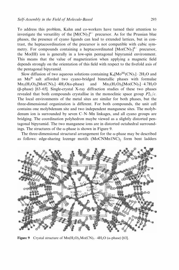
To address this problem, Kahn and co-workers have turned their attention to
investigate the versatility of the [M(CN)7]nÿ precursor. As for the Prussian blue
phases, the presence of cyano ligands can lead to extended lattices, but in con-
trast, the heptacoordination of the precursor is not compatible with cubic sym-
metry. For compounds containing a heptacoordinated [Mo(CN)7]4ÿ precursor,
the Mo(III) ion is generally in a low-spin pentagonal bipyramid environment.
This means that the value of magnetization when applying a magnetic ®eld
depends strongly on the orientation of this ®eld with respect to the ®vefold axis of
the pentagonal bipyramid.
Slow diffusion of two aqueous solutions containing K4[MoIII(CN)7] � 2H2O and
an MnII salt afforded two cyano-bridged bimetallic phases with formulae
Mn2(H2O)5[Mo(CN)7] � 4H2O(a-phase) and Mn2(H2O)5[Mo(CN)7] � 4:7H2O
(b-phase) [63±65]. Single-crystal X-ray diffraction studies of these two phases
revealed that both compounds crystallise in the monoclinic space group P21=c.
The local environments of the metal sites are similar for both phases, but the
three-dimensional organization is different. For both compounds, the unit cell
contains one molybdenum site and two independent manganese sites. The molyb-
denum ion is surrounded by seven C±N±Mn linkages, and all cyano groups are
bridging. The coordination polyhedron maybe viewed as a slightly distorted pen-
tagonal bipyramid. The two manganese ions are in distorted octahedral surround-
ings. The structures of the a-phase is shown in Figure 9.
The three-dimensional structural arrangement for the a-phase may be described
as follows: edge-sharing lozenge motifs (MoCNMn1NC)2 form bent ladders
Mn1
N3 N3N1
N1
C1
C1
C4
C5
O2
Mn1O1
N4
C3
C3
N2N2
N7
N6
N5
O4
O3C2
C2
Mol
O5
Mn2
Mn1
Mn2
Figure 9 Crystal structure of Mn(H2O)5Mo(CN)7 � 4H2O (a-phase) [63].
Self-Assembly in the Field of Molecule-Based 293
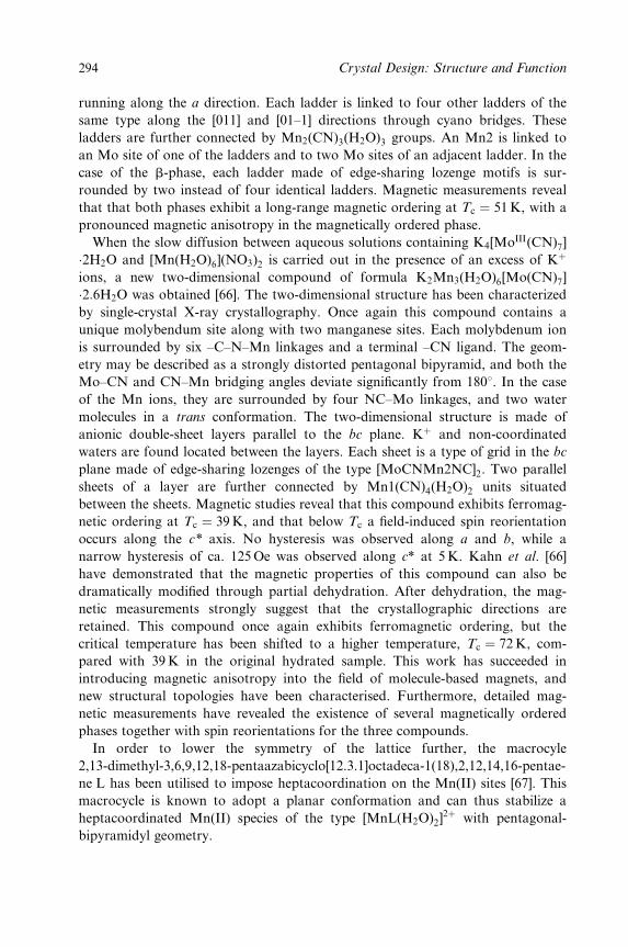
running along the a direction. Each ladder is linked to four other ladders of the
same type along the [011] and [01±1] directions through cyano bridges. These
ladders are further connected by Mn2(CN)3(H2O)3 groups. An Mn2 is linked to
an Mo site of one of the ladders and to two Mo sites of an adjacent ladder. In the
case of the b-phase, each ladder made of edge-sharing lozenge motifs is sur-
rounded by two instead of four identical ladders. Magnetic measurements reveal
that that both phases exhibit a long-range magnetic ordering at Tc � 51K, with a
pronounced magnetic anisotropy in the magnetically ordered phase.
When the slow diffusion between aqueous solutions containing K4[MoIII(CN)7]
�2H2O and [Mn(H2O)6](NO3)2 is carried out in the presence of an excess of K�
ions, a new two-dimensional compound of formula K2Mn3(H2O)6[Mo(CN)7]
�2:6H2O was obtained [66]. The two-dimensional structure has been characterized
by single-crystal X-ray crystallography. Once again this compound contains a
unique molybendum site along with two manganese sites. Each molybdenum ion
is surrounded by six ±C±N±Mn linkages and a terminal ±CN ligand. The geom-
etry may be described as a strongly distorted pentagonal bipyramid, and both the
Mo±CN and CN±Mn bridging angles deviate signi®cantly from 1808. In the case
of the Mn ions, they are surrounded by four NC±Mo linkages, and two water
molecules in a trans conformation. The two-dimensional structure is made of
anionic double-sheet layers parallel to the bc plane. K� and non-coordinated
waters are found located between the layers. Each sheet is a type of grid in the bc
plane made of edge-sharing lozenges of the type [MoCNMn2NC]2. Two parallel
sheets of a layer are further connected by Mn1(CN)4(H2O)2 units situated
between the sheets. Magnetic studies reveal that this compound exhibits ferromag-
netic ordering at Tc � 39K, and that below Tc a ®eld-induced spin reorientation
occurs along the c* axis. No hysteresis was observed along a and b, while a
narrow hysteresis of ca. 125Oe was observed along c* at 5K. Kahn et al. [66]
have demonstrated that the magnetic properties of this compound can also be
dramatically modi®ed through partial dehydration. After dehydration, the mag-
netic measurements strongly suggest that the crystallographic directions are
retained. This compound once again exhibits ferromagnetic ordering, but the
critical temperature has been shifted to a higher temperature, Tc � 72 K, com-
pared with 39K in the original hydrated sample. This work has succeeded in
introducing magnetic anisotropy into the ®eld of molecule-based magnets, and
new structural topologies have been characterised. Furthermore, detailed mag-
netic measurements have revealed the existence of several magnetically ordered
phases together with spin reorientations for the three compounds.
In order to lower the symmetry of the lattice further, the macrocyle
2,13-dimethyl-3,6,9,12,18-pentaazabicyclo[12.3.1]octadeca-1(18),2,12,14,16-pentae-
ne L has been utilised to impose heptacoordination on the Mn(II) sites [67]. This
macrocycle is known to adopt a planar conformation and can thus stabilize a
heptacoordinated Mn(II) species of the type [MnL(H2O)2]2� with pentagonal-
bipyramidyl geometry.
294 Crystal Design: Structure and Function
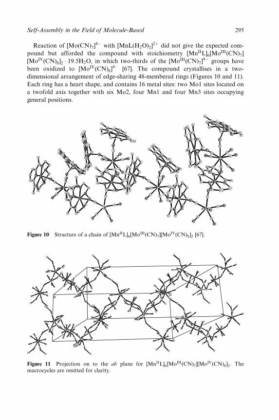
Reaction of [Mo(CN)7]4ÿ with [MnL(H2O)2]
2� did not give the expected com-
pound but afforded the compound with stoichiometry [MnIIL]6[MoIII(CN)7]
[MoIV(CN)8]2 � 19:5H2O, in which two-thirds of the [MoIII(CN)7]4ÿ groups have
been oxidized to [MoIV(CN)8]4ÿ [67]. The compound crystallises in a two-
dimensional arrangement of edge-sharing 48-membered rings (Figures 10 and 11).
Each ring has a heart shape, and contains 16 metal sites: two Mo1 sites located on
a twofold axis together with six Mo2, four Mn1 and four Mn3 sites occupying
general positions.
Figure 10 Structure of a chain of [MnIIL]6[MoIII(CN)7][MoIV(CN)8]2 [67].
Figure 11 Projection on to the ab plane for [MnIIL]6[MoIII(CN)7][MoIV(CN)8]2. Themacrocycles are omitted for clarity.
Self-Assembly in the Field of Molecule-Based 295
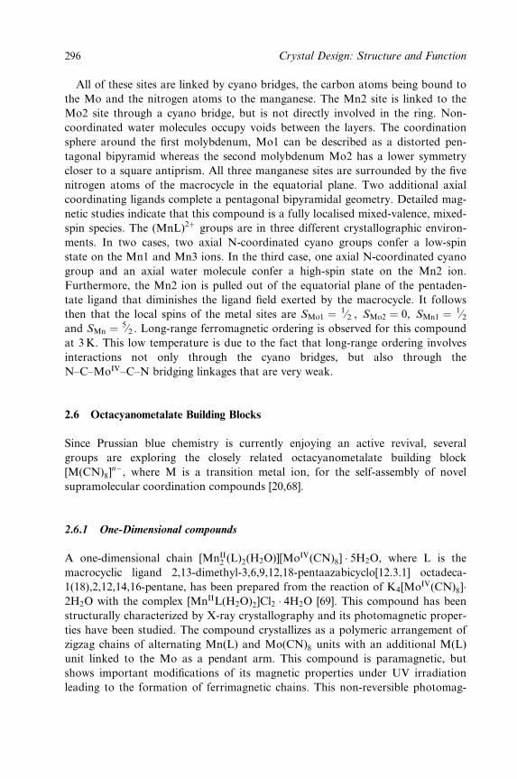
All of these sites are linked by cyano bridges, the carbon atoms being bound to
the Mo and the nitrogen atoms to the manganese. The Mn2 site is linked to the
Mo2 site through a cyano bridge, but is not directly involved in the ring. Non-
coordinated water molecules occupy voids between the layers. The coordination
sphere around the ®rst molybdenum, Mo1 can be described as a distorted pen-
tagonal bipyramid whereas the second molybdenum Mo2 has a lower symmetry
closer to a square antiprism. All three manganese sites are surrounded by the ®ve
nitrogen atoms of the macrocycle in the equatorial plane. Two additional axial
coordinating ligands complete a pentagonal bipyramidal geometry. Detailed mag-
netic studies indicate that this compound is a fully localised mixed-valence, mixed-
spin species. The (MnL)2� groups are in three different crystallographic environ-
ments. In two cases, two axial N-coordinated cyano groups confer a low-spin
state on the Mn1 and Mn3 ions. In the third case, one axial N-coordinated cyano
group and an axial water molecule confer a high-spin state on the Mn2 ion.
Furthermore, the Mn2 ion is pulled out of the equatorial plane of the pentaden-
tate ligand that diminishes the ligand ®eld exerted by the macrocycle. It follows
then that the local spins of the metal sites are SMo1 � 1¤2 , SMo2 � 0, SMn1 � 1¤2and SMn � 5¤2 . Long-range ferromagnetic ordering is observed for this compound
at 3K. This low temperature is due to the fact that long-range ordering involves
interactions not only through the cyano bridges, but also through the
N±C±MoIV±C±N bridging linkages that are very weak.
2.6 Octacyanometalate Building Blocks
Since Prussian blue chemistry is currently enjoying an active revival, several
groups are exploring the closely related octacyanometalate building block
[M(CN)8]nÿ, where M is a transition metal ion, for the self-assembly of novel
supramolecular coordination compounds [20,68].
2.6.1 One-Dimensional compounds
A one-dimensional chain [MnII2 (L)2(H2O)][MoIV(CN)8] � 5H2O, where L is the
macrocyclic ligand 2,13-dimethyl-3,6,9,12,18-pentaazabicyclo[12.3.1] octadeca-
1(18),2,12,14,16-pentane, has been prepared from the reaction of K4[MoIV(CN)8]�2H2O with the complex [MnIIL(H2O)2]Cl2 � 4H2O [69]. This compound has been
structurally characterized by X-ray crystallography and its photomagnetic proper-
ties have been studied. The compound crystallizes as a polymeric arrangement of
zigzag chains of alternating Mn(L) and Mo(CN)8 units with an additional M(L)
unit linked to the Mo as a pendant arm. This compound is paramagnetic, but
shows important modi®cations of its magnetic properties under UV irradiation
leading to the formation of ferrimagnetic chains. This non-reversible photomag-
296 Crystal Design: Structure and Function
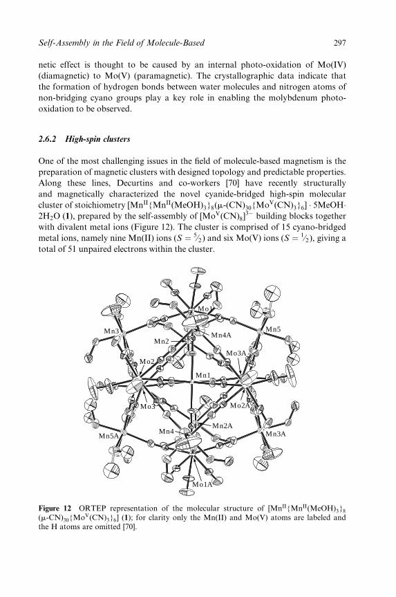
netic effect is thought to be caused by an internal photo-oxidation of Mo(IV)
(diamagnetic) to Mo(V) (paramagnetic). The crystallographic data indicate that
the formation of hydrogen bonds between water molecules and nitrogen atoms of
non-bridging cyano groups play a key role in enabling the molybdenum photo-
oxidation to be observed.
2.6.2 High-spin clusters
One of the most challenging issues in the ®eld of molecule-based magnetism is the
preparation of magnetic clusters with designed topology and predictable properties.
Along these lines, Decurtins and co-workers [70] have recently structurally
and magnetically characterized the novel cyanide-bridged high-spin molecular
cluster of stoichiometry [MnII{MnII(MeOH)3}8(m-(CN)30{MoV(CN)3}6] � 5MeOH�2H2O (1), prepared by the self-assembly of [MoV(CN)8]
3ÿ building blocks together
with divalent metal ions (Figure 12). The cluster is comprised of 15 cyano-bridged
metal ions, namely nine Mn(II) ions (S � 5¤2) and six Mo(V) ions (S � 1¤2), giving a
total of 51 unpaired electrons within the cluster.
Mo1
Mn3
Mn1
Mn2Mn4A
Mo2
Mo3
Mn5A
Mn5
Mn3A
Mo3A
Mo2A
Mn2A
Mo1A
Mn4
Figure 12 ORTEP representation of the molecular structure of [MnII{MnII(MeOH)3}8
(m-CN)30{MoV(CN)3}6] (1); for clarity only the Mn(II) and Mo(V) atoms are labeled andthe H atoms are omitted [70].
Self-Assembly in the Field of Molecule-Based 297
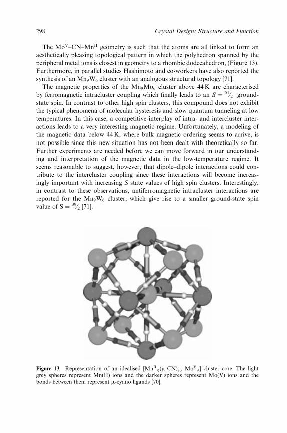
The MoV±CN±MnII geometry is such that the atoms are all linked to form an
aesthetically pleasing topological pattern in which the polyhedron spanned by the
peripheral metal ions is closest in geometry to a rhombic dodecahedron, (Figure 13).
Furthermore, in parallel studies Hashimoto and co-workers have also reported the
synthesis of an Mn9W6 cluster with an analogous structural topology [71].
The magnetic properties of the Mn9Mo6 cluster above 44K are characterised
by ferromagnetic intracluster coupling which ®nally leads to an S � 51¤2 ground-
state spin. In contrast to other high spin clusters, this compound does not exhibit
the typical phenomena of molecular hysteresis and slow quantum tunneling at low
temperatures. In this case, a competitive interplay of intra- and intercluster inter-
actions leads to a very interesting magnetic regime. Unfortunately, a modeling of
the magnetic data below 44K, where bulk magnetic ordering seems to arrive, is
not possible since this new situation has not been dealt with theoretically so far.
Further experiments are needed before we can move forward in our understand-
ing and interpretation of the magnetic data in the low-temperature regime. It
seems reasonable to suggest, however, that dipole±dipole interactions could con-
tribute to the intercluster coupling since these interactions will become increas-
ingly important with increasing S state values of high spin clusters. Interestingly,
in contrast to these observations, antiferromagnetic intracluster interactions are
reported for the Mn9W6 cluster, which give rise to a smaller ground-state spin
value of S � 39¤2 [71].
Figure 13 Representation of an idealised [MnII9(m-CN)30±MoV
6] cluster core. The lightgrey spheres represent Mn(II) ions and the darker spheres represent Mo(V) ions and thebonds between them represent m-cyano ligands [70].
298 Crystal Design: Structure and Function
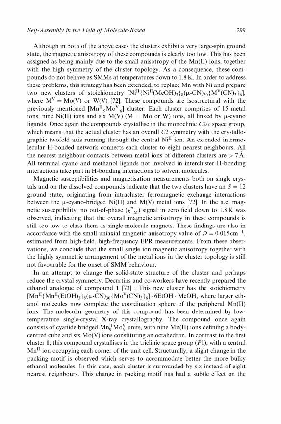
Although in both of the above cases the clusters exhibit a very large-spin ground
state, the magnetic anisotropy of these compounds is clearly too low. This has been
assigned as being mainly due to the small anisotropy of the Mn(II) ions, together
with the high symmetry of the cluster topology. As a consequence, these com-
pounds do not behave as SMMs at temperatures down to 1.8 K. In order to address
these problems, this strategy has been extended, to replace Mn with Ni and prepare
two new clusters of stoichiometry [NiII{NiII(MeOH)3}8(m-CN)30{MV(CN)3}6],
where MV �Mo(V) or W(V) [72]. These compounds are isostructural with the
previously mentioned [MnII9MoV
6] cluster. Each cluster comprises of 15 metal
ions, nine Ni(II) ions and six M(V) (M � Mo or W) ions, all linked by m-cyano
ligands. Once again the compounds crystallise in the monoclinic C2/c space group,
which means that the actual cluster has an overall C2 symmetry with the crystallo-
graphic twofold axis running through the central NiII ion. An extended intermo-
lecular H-bonded network connects each cluster to eight nearest neighbours. All
the nearest neighbour contacts between metal ions of different clusters are > 7 AÊ .
All terminal cyano and methanol ligands not involved in intercluster H-bonding
interactions take part in H-bonding interactions to solvent molecules.
Magnetic susceptibilities and magnetisation measurements both on single crys-
tals and on the dissolved compounds indicate that the two clusters have an S � 12
ground state, originating from intracluster ferromagnetic exchange interactions
between the m-cyano-bridged Ni(II) and M(V) metal ions [72]. In the a.c. mag-
netic susceptibility, no out-of-phase (x00M) signal in zero ®eld down to 1.8 K was
observed, indicating that the overall magnetic anisotropy in these compounds is
still too low to class them as single-molecule magnets. These ®ndings are also in
accordance with the small uniaxial magnetic anisotropy value of D � 0:015 cmÿ1,
estimated from high-®eld, high-frequency EPR measurements. From these obser-
vations, we conclude that the small single ion magnetic anisotropy together with
the highly symmetric arrangement of the metal ions in the cluster topology is still
not favourable for the onset of SMM behaviour.
In an attempt to change the solid-state structure of the cluster and perhaps
reduce the crystal symmetry, Decurtins and co-workers have recently prepared the
ethanol analogue of compound 1 [73] . This new cluster has the stoichiometry
[MnII{MnII(EtOH)3}8(m-CN)30{MoV(CN)3}6] � 6EtOH �MeOH, where larger eth-
anol molecules now complete the coordination sphere of the peripheral Mn(II)
ions. The molecular geometry of this compound has been determined by low-
temperature single-crystal X-ray crystallography. The compound once again
consists of cyanide bridged MnII9 MoV
6 units, with nine Mn(II) ions de®ning a body-
centred cube and six Mo(V) ions constituting an octahedron. In contrast to the ®rst
cluster 1, this compound crystallises in the triclinic space group (P1), with a central
MnII ion occupying each corner of the unit cell. Structurally, a slight change in the
packing motif is observed which serves to accommodate better the more bulky
ethanol molecules. In this case, each cluster is surrounded by six instead of eight
nearest neighbours. This change in packing motif has had a subtle effect on the
Self-Assembly in the Field of Molecule-Based 299
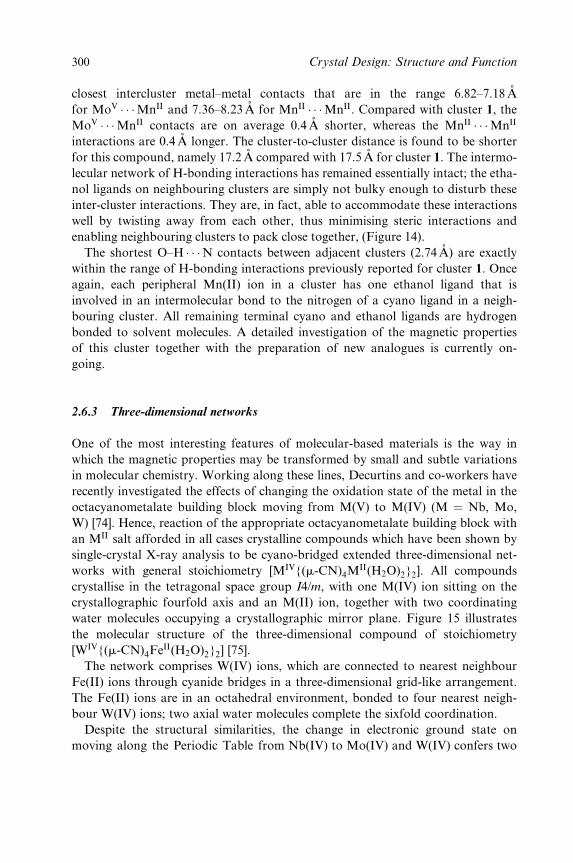
closest intercluster metal±metal contacts that are in the range 6.82±7.18AÊ
for MoV � � �MnII and 7.36±8.23AÊ for MnII � � �MnII. Compared with cluster 1, the
MoV � � �MnII contacts are on average 0.4 AÊ shorter, whereas the MnII � � �MnII
interactions are 0.4 AÊ longer. The cluster-to-cluster distance is found to be shorter
for this compound, namely 17.2 AÊ compared with 17.5AÊ for cluster 1. The intermo-
lecular network of H-bonding interactions has remained essentially intact; the etha-
nol ligands on neighbouring clusters are simply not bulky enough to disturb these
inter-cluster interactions. They are, in fact, able to accommodate these interactions
well by twisting away from each other, thus minimising steric interactions and
enabling neighbouring clusters to pack close together, (Figure 14).
The shortest O±H � � �N contacts between adjacent clusters (2.74 AÊ ) are exactly
within the range of H-bonding interactions previously reported for cluster 1. Once
again, each peripheral Mn(II) ion in a cluster has one ethanol ligand that is
involved in an intermolecular bond to the nitrogen of a cyano ligand in a neigh-
bouring cluster. All remaining terminal cyano and ethanol ligands are hydrogen
bonded to solvent molecules. A detailed investigation of the magnetic properties
of this cluster together with the preparation of new analogues is currently on-
going.
2.6.3 Three-dimensional networks
One of the most interesting features of molecular-based materials is the way in
which the magnetic properties may be transformed by small and subtle variations
in molecular chemistry. Working along these lines, Decurtins and co-workers have
recently investigated the effects of changing the oxidation state of the metal in the
octacyanometalate building block moving from M(V) to M(IV) (M � Nb, Mo,
W) [74]. Hence, reaction of the appropriate octacyanometalate building block with
an MII salt afforded in all cases crystalline compounds which have been shown by
single-crystal X-ray analysis to be cyano-bridged extended three-dimensional net-
works with general stoichiometry [MIV{(m-CN)4MII(H2O)2}2]. All compounds
crystallise in the tetragonal space group I4/m, with one M(IV) ion sitting on the
crystallographic fourfold axis and an M(II) ion, together with two coordinating
water molecules occupying a crystallographic mirror plane. Figure 15 illustrates
the molecular structure of the three-dimensional compound of stoichiometry
[WIV{(m-CN)4FeII(H2O)2}2] [75].
The network comprises W(IV) ions, which are connected to nearest neighbour
Fe(II) ions through cyanide bridges in a three-dimensional grid-like arrangement.
The Fe(II) ions are in an octahedral environment, bonded to four nearest neigh-
bour W(IV) ions; two axial water molecules complete the sixfold coordination.
Despite the structural similarities, the change in electronic ground state on
moving along the Periodic Table from Nb(IV) to Mo(IV) and W(IV) confers two
300 Crystal Design: Structure and Function
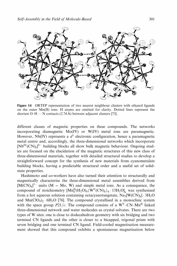
Figure 14 ORTEP representation of two nearest neighbour clusters with ethanol ligandson the outer Mn(II) ions. H atoms are omitted for clarity. Dotted lines represent theshortest O±H � � �N contacts (2.74 AÊ ) between adjacent clusters [73].
different classes of magnetic properties on these compounds. The networks
incorporating diamagnetic Mo(IV) or W(IV) metal ions are paramagnetic.
However, Nb(IV) represents a d1 electronic con®guration, hence a paramagnetic
metal centre and, accordingly, the three-dimensional networks which incorporate
[NbIV(CN)8]4ÿ building blocks all show bulk magnetic behaviour. Ongoing stud-
ies are focused on the elucidation of the magnetic structures of this new class of
three-dimensional materials, together with detailed structural studies to develop a
straightforward concept for the synthesis of new materials from cyanometalate
building blocks, having a predictable structural order and a useful set of solid-
state properties.
Hashimoto and co-workers have also turned their attention to structurally and
magnetically characterise the three-dimensional metal assemblies derived from
[M(CN)8]3ÿ units (M � Mo, W) and simple metal ions. As a consequence, the
compound of stoichiometry [MnII6 (H2O)9{W
V(CN)8}4 � 13H2O]n
was synthesised
from a hot aqueous solution containing octacyanotungstate, Na3[W(CN)8] � 3H2O
and Mn(ClO4)2 � 6H2O [76]. The compound crystallised in a monoclinic system
with the space group P21=c. The compound consists of a WV±CN±MnII linked
three-dimensional network and water molecules as crystal solvates. There are two
types of W sites: one is close to dodecahedron geometry with six bridging and two
terminal CN ligands and the other is closer to a bicapped, trigonal prism with
seven bridging and one terminal CN ligand. Field-cooled magnetisation measure-
ment showed that this compound exhibits a spontaneous magnetisation below
Self-Assembly in the Field of Molecule-Based 301
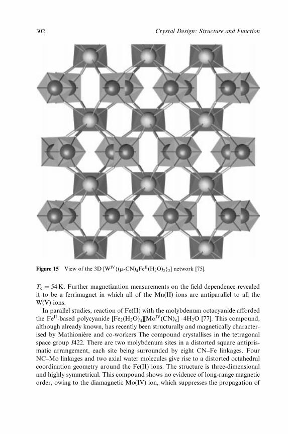
Figure 15 View of the 3D [WIV{(m-CN)4FeII(H2O)2}2] network [75].
Tc � 54 K. Further magnetization measurements on the ®eld dependence revealed
it to be a ferrimagnet in which all of the Mn(II) ions are antiparallel to all the
W(V) ions.
In parallel studies, reaction of Fe(II) with the molybdenum octacyanide afforded
the FeII-based polycyanide [Fe2(H2O)4][MoIV(CN)8] � 4H2O [77]. This compound,
although already known, has recently been structurally and magnetically character-
ised by MathionieÁre and co-workers The compound crystallises in the tetragonal
space group I422. There are two molybdenum sites in a distorted square antipris-
matic arrangement, each site being surrounded by eight CN±Fe linkages. Four
NC±Mo linkages and two axial water molecules give rise to a distorted octahedral
coordination geometry around the Fe(II) ions. The structure is three-dimensional
and highly symmetrical. This compound shows no evidence of long-range magnetic
order, owing to the diamagnetic Mo(IV) ion, which suppresses the propagation of
302 Crystal Design: Structure and Function
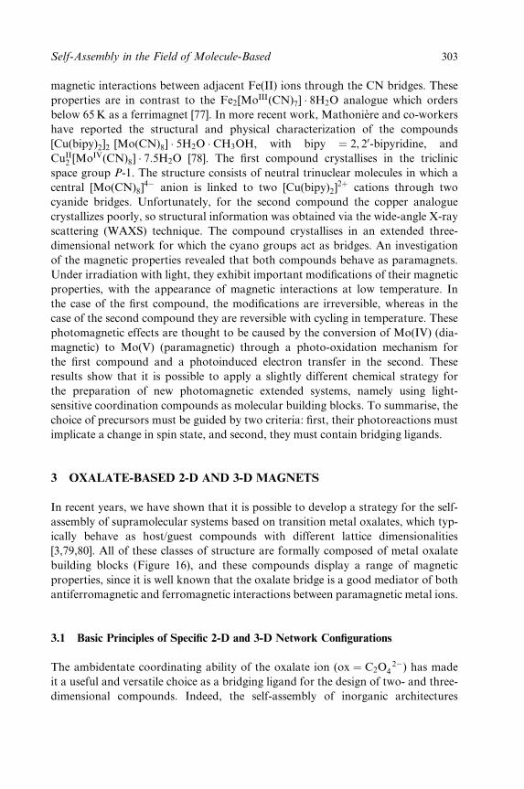
magnetic interactions between adjacent Fe(II) ions through the CN bridges. These
properties are in contrast to the Fe2[MoIII(CN)7] � 8H2O analogue which orders
below 65 K as a ferrimagnet [77]. In more recent work, MathonieÁre and co-workers
have reported the structural and physical characterization of the compounds
[Cu(bipy)2]2 [Mo(CN)8] � 5H2O � CH3OH, with bipy � 2, 20-bipyridine, and
CuII2 [MoIV(CN)8] � 7:5H2O [78]. The ®rst compound crystallises in the triclinic
space group P-1. The structure consists of neutral trinuclear molecules in which a
central [Mo(CN)8]4ÿ anion is linked to two [Cu(bipy)2]
2� cations through two
cyanide bridges. Unfortunately, for the second compound the copper analogue
crystallizes poorly, so structural information was obtained via the wide-angle X-ray
scattering (WAXS) technique. The compound crystallises in an extended three-
dimensional network for which the cyano groups act as bridges. An investigation
of the magnetic properties revealed that both compounds behave as paramagnets.
Under irradiation with light, they exhibit important modi®cations of their magnetic
properties, with the appearance of magnetic interactions at low temperature. In
the case of the ®rst compound, the modi®cations are irreversible, whereas in the
case of the second compound they are reversible with cycling in temperature. These
photomagnetic effects are thought to be caused by the conversion of Mo(IV) (dia-
magnetic) to Mo(V) (paramagnetic) through a photo-oxidation mechanism for
the ®rst compound and a photoinduced electron transfer in the second. These
results show that it is possible to apply a slightly different chemical strategy for
the preparation of new photomagnetic extended systems, namely using light-
sensitive coordination compounds as molecular building blocks. To summarise, the
choice of precursors must be guided by two criteria: ®rst, their photoreactions must
implicate a change in spin state, and second, they must contain bridging ligands.
3 OXALATE-BASED 2-D AND 3-D MAGNETS
In recent years, we have shown that it is possible to develop a strategy for the self-
assembly of supramolecular systems based on transition metal oxalates, which typ-
ically behave as host/guest compounds with different lattice dimensionalities
[3,79,80]. All of these classes of structure are formally composed of metal oxalate
building blocks (Figure 16), and these compounds display a range of magnetic
properties, since it is well known that the oxalate bridge is a good mediator of both
antiferromagnetic and ferromagnetic interactions between paramagnetic metal ions.
3.1 Basic Principles of Speci®c 2-D and 3-D Network Con®gurations
The ambidentate coordinating ability of the oxalate ion (ox � C2O2ÿ
4 ) has made
it a useful and versatile choice as a bridging ligand for the design of two- and three-
dimensional compounds. Indeed, the self-assembly of inorganic architectures
Self-Assembly in the Field of Molecule-Based 303
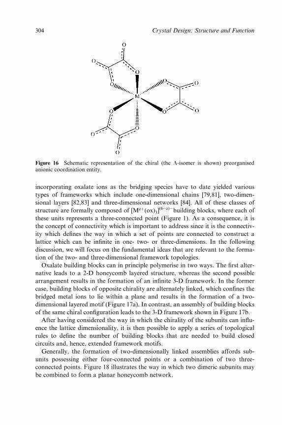
Figure 16 Schematic representation of the chiral (the L-isomer is shown) preorganisedanionic coordination entity.
incorporating oxalate ions as the bridging species have to date yielded various
types of frameworks which include one-dimensional chains [79,81], two-dimen-
sional layers [82,83] and three-dimensional networks [84]. All of these classes of
structure are formally composed of [Mz�(ox)3](6ÿz)ÿbuilding blocks, where each of
these units represents a three-connected point (Figure 1). As a consequence, it is
the concept of connectivity which is important to address since it is the connectiv-
ity which de®nes the way in which a set of points are connected to construct a
lattice which can be in®nite in one- two- or three-dimensions. In the following
discussion, we will focus on the fundamental ideas that are relevant to the forma-
tion of the two- and three-dimensional framework topologies.
Oxalate building blocks can in principle polymerise in two ways. The ®rst alter-
native leads to a 2-D honeycomb layered structure, whereas the second possible
arrangement results in the formation of an in®nite 3-D framework. In the former
case, building blocks of opposite chirality are alternately linked, which con®nes the
bridged metal ions to lie within a plane and results in the formation of a two-
dimensional layered motif (Figure 17a). In contrast, an assembly of building blocks
of the same chiral con®guration leads to the 3-D framework shown in Figure 17b.
After having considered the way in which the chirality of the subunits can in¯u-
ence the lattice dimensionality, it is then possible to apply a series of topological
rules to de®ne the number of building blocks that are needed to build closed
circuits and, hence, extended framework motifs.
Generally, the formation of two-dimensionally linked assemblies affords sub-
units possessing either four-connected points or a combination of two three-
connected points. Figure 18 illustrates the way in which two dimeric subunits may
be combined to form a planar honeycomb network.
304 Crystal Design: Structure and Function
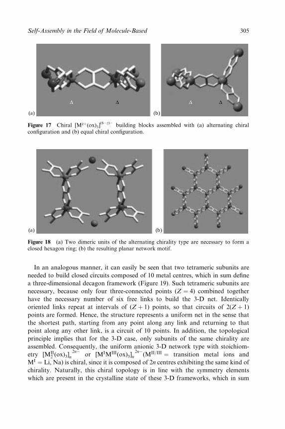
∆ ∆ ∆ ∆
(a) (b)
Figure 17 Chiral [Mz�(ox)3](6ÿz)ÿ
building blocks assembled with (a) alternating chiralcon®guration and (b) equal chiral con®guration.
(a) (b)
Figure 18 (a) Two dimeric units of the alternating chirality type are necessary to form aclosed hexagon ring; (b) the resulting planar network motif.
In an analogous manner, it can easily be seen that two tetrameric subunits are
needed to build closed circuits composed of 10 metal centres, which in sum de®ne
a three-dimensional decagon framework (Figure 19). Such tetrameric subunits are
necessary, because only four three-connected points (Z � 4) combined together
have the necessary number of six free links to build the 3-D net. Identically
oriented links repeat at intervals of (Z � 1) points, so that circuits of 2(Z � 1)
points are formed. Hence, the structure represents a uniform net in the sense that
the shortest path, starting from any point along any link and returning to that
point along any other link, is a circuit of 10 points. In addition, the topological
principle implies that for the 3-D case, only subunits of the same chirality are
assembled. Consequently, the uniform anionic 3-D network type with stoichiom-
etry [MII2 (ox)3]
2nÿn or [MIMIII(ox)3]
2nÿn (MII=III � transition metal ions and
MI � Li, Na) is chiral, since it is composed of 2n centres exhibiting the same kind of
chirality. Naturally, this chiral topology is in line with the symmetry elements
which are present in the crystalline state of these 3-D frameworks, which in sum
Self-Assembly in the Field of Molecule-Based 305
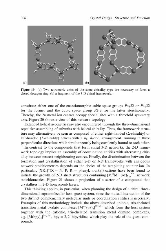
(a) (b)
Figure 19 (a) Two tetrameric units of the same chirality type are necessary to form aclosed decagon ring; (b) a fragment of the 3-D chiral framework.
constitute either one of the enantiomorphic cubic space groups P4332 or P4132
for the former and the cubic space group P213 for the latter stoichiometry.
Thereby, the 2n metal ion centres occupy special sites with a threefold symmetry
axis. Figure 20 shows a view of this network topology.
Extended helical geometries are also encountered through the three-dimensional
repetitive assembling of subunits with helical chirality. Thus, the framework struc-
ture may alternatively be seen as composed of either right-handed (D-chirality) or
left-handed (L-chirality) helices with a 41, 43or21 arrangement, running in three
perpendicular directions while simultaneously being covalently bound to each other.
In contrast to the compounds that form chiral 3-D networks, the 2-D frame-
work topology implies an assembly of coordination entities with alternating chir-
ality between nearest neighbouring centres. Finally, the discrimination between the
formation and crystallisation of either 2-D or 3-D frameworks with analogous
network stoichiometries depends on the choice of the templating counter-ion. In
particular, [XR4]�(X � N, P; R � phenyl, n-alkyl) cations have been found to
initiate the growth of 2-D sheet structures containing [MIIMIII(ox)3]nÿ
n , network
stoichiometries. Figure 21 shows a projection of a sector of a compound that
crystallises in 2-D honeycomb layers.
This thinking applies, in particular, when planning the design of a chiral three-
dimensional supramolecular host±guest system, since the mutual interaction of the
two distinct complementary molecular units or coordination entities is necessary.
Examples of this methodology include the above-described anionic, tris-chelated
transition metal oxalato complexes [Mz�(ox)3](6ÿz)ÿ
which form the host system
together with the cationic, tris-chelated transition metal diimino complexes,
e.g. [M(bpy)3]2�=3�, bpy � 2, 20-bipyridine, which play the role of the guest com-
pounds.
306 Crystal Design: Structure and Function
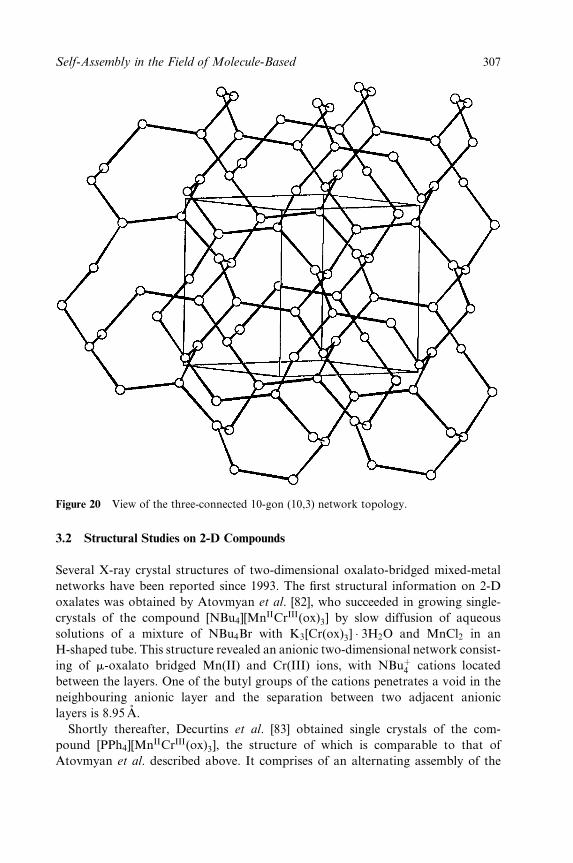
Figure 20 View of the three-connected 10-gon (10,3) network topology.
3.2 Structural Studies on 2-D Compounds
Several X-ray crystal structures of two-dimensional oxalato-bridged mixed-metal
networks have been reported since 1993. The ®rst structural information on 2-D
oxalates was obtained by Atovmyan et al. [82], who succeeded in growing single-
crystals of the compound [NBu4][MnIICrIII(ox)3] by slow diffusion of aqueous
solutions of a mixture of NBu4Br with K3[Cr(ox)3] � 3H2O and MnCl2 in an
H-shaped tube. This structure revealed an anionic two-dimensional network consist-
ing of m-oxalato bridged Mn(II) and Cr(III) ions, with NBu�4 cations located
between the layers. One of the butyl groups of the cations penetrates a void in the
neighbouring anionic layer and the separation between two adjacent anionic
layers is 8.95 AÊ .
Shortly thereafter, Decurtins et al. [83] obtained single crystals of the com-
pound [PPh4][MnIICrIII(ox)3], the structure of which is comparable to that of
Atovmyan et al. described above. It comprises of an alternating assembly of the
Self-Assembly in the Field of Molecule-Based 307
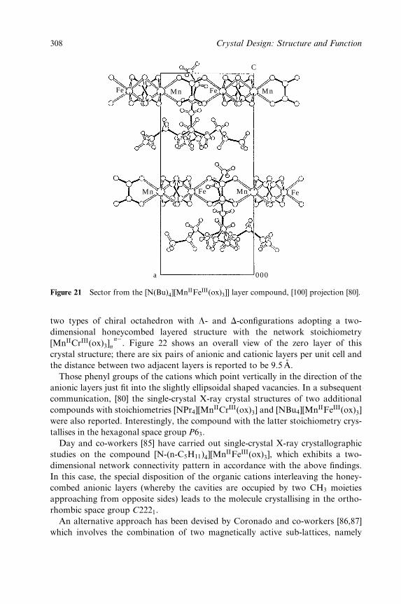
Mn MnFe
Mn
a 000
Fe Mn Fe
Fe
C
Figure 21 Sector from the [N(Bu)4][MnIIFeIII(ox)3]] layer compound, [100] projection [80].
two types of chiral octahedron with L- and D-con®gurations adopting a two-
dimensional honeycombed layered structure with the network stoichiometry
[MnIICrIII(ox)3]nÿ
n . Figure 22 shows an overall view of the zero layer of this
crystal structure; there are six pairs of anionic and cationic layers per unit cell and
the distance between two adjacent layers is reported to be 9.5 AÊ .
Those phenyl groups of the cations which point vertically in the direction of the
anionic layers just ®t into the slightly ellipsoidal shaped vacancies. In a subsequent
communication, [80] the single-crystal X-ray crystal structures of two additional
compounds with stoichiometries [NPr4][MnIICrIII(ox)3] and [NBu4][MnIIFeIII(ox)3]
were also reported. Interestingly, the compound with the latter stoichiometry crys-
tallises in the hexagonal space group P63.
Day and co-workers [85] have carried out single-crystal X-ray crystallographic
studies on the compound [N-(n-C5H11)4][MnIIFeIII(ox)3], which exhibits a two-
dimensional network connectivity pattern in accordance with the above ®ndings.
In this case, the special disposition of the organic cations interleaving the honey-
combed anionic layers (whereby the cavities are occupied by two CH3 moieties
approaching from opposite sides) leads to the molecule crystallising in the ortho-
rhombic space group C2221.
An alternative approach has been devised by Coronado and co-workers [86,87]
which involves the combination of two magnetically active sub-lattices, namely
308 Crystal Design: Structure and Function
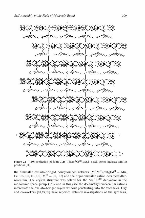
Figure 22 [110] projection of [N(n-C3H7)4][MnIICrIII(ox)3]. Black atoms indicate Mn(II)positions [80].
the bimetallic oxalato-bridged honeycombed network [MIIMIII(ox)3](MII � Mn,
Fe, Co, Cr, Ni, Cu; MIII � Cr, Fe) and the organometallic cation decamethylfer-
rocenium. The crystal structure was solved for the MnIIFeIII derivative in the
monoclinic space group C2/m and in this case the decamethylferrocenium cations
intercalate the oxalato-bridged layers without penetrating into the vacancies. Day
and co-workers [88,89,90] have reported detailed investigations of the synthesis,
Self-Assembly in the Field of Molecule-Based 309
structural and magnetic characterisation of a series of mixed-valence compounds
with stoichiometries of the type [A][CrIICrIII(ox)3] and [A][FeIIFeIII(ox)3], together
with mixed-metal compounds of stoichiometry [A][MnIIFeIII(ox)3]. In their work,
all of the phases prepared with a wide variety of organic template cations [A] were
structurally characterised by X-ray powder diffraction, and the re¯ections indexed
and unit cell constants re®ned on a hexagonal cell; all of the these structures have
been proved to be consistent with a 2-D honeycomb network. The systematic
variation of [A] was aimed at modulating the separation between the layers and
hence varying the physical properties.
3.3 Magnetic Studies on 2-D Compounds
These 2-D polymeric materials all exhibit a wide range of magnetic behaviour and
ferro-, ferri- or antiferromagnetic long-range ordering processes have all been
observed. Generally, the magnetic interactions and magnetic ordering in the
[A][MIIMIII(ox)3] materials are strongly dependent on the character of the cations
and the combination of MIIMIII metal ions.
In 1992, Okawa and co-workers [91,92] reported a synthetic and magnetic study
on ferri- and ferromagnetic mixed metal assemblies with the stoichiometry
[NBu4][MIIMIII(ox)3] (MII � Mn, Fe, Co, Ni, Cu, Zn; MIII � Cr, Fe). At that
time, these compounds were falsely assumed to have a 3-D network structure, but
in subsequent reports by Atovmyan et al. [82] and Decurtins et al. [83], the veri®-
cation of the two-dimensional class of structure has since been proved. The series
of Cr(III) derivatives show a ferromagnetic phase transition with Tc < 14 K and
magnetic hysteresis loops with coercive ®elds Hc < 320G. The Fe(III) compounds
with MII � Fe, Ni have been shown to behave as ferrimagnets with magnetic
phase transition temperatures of 43 and 28 K, respectively. [91]
In 1994, Day and co-workers [89] reported the results from a detailed investi-
gation of the mixed-valence ferrimagnets [A][FeIIFeIII(ox)3] (A � quaternary am-
monium or phosphonium). In a later communication [93], these authors presented
a more comprehensive study on the temperature-dependent magnetisation in these
[A][FeIIFeIII(ox)3] layer compounds, and discussed the manifestation of NeÂel N-
and Q-type ferrimagnetism. The major aim of these studies was to map and
identify the reasons to account for the presence of negative magnetisation at low
temperature. According to NeÂel, the ground state of a ferrimagnet is determined
by the saturation magnetisations of each magnetic sub-lattice and their relative
ordering rates with respect to temperature. For the honeycomb lattice with alter-
nating Fe(II) and Fe(III) ions, this situation corresponds to an initially steeper
ordering on the Fe(II) sub-lattice.
The mixed-valence compound with stoichiometry [A][CrIICrIII(ox)3] (A � NBu4,
P(Ph)4) has also been synthesised and fully characterised structurally and magnet-
ically [88]. Again, although short-range antiferromagnetic correlations were ob-
310 Crystal Design: Structure and Function
served below 100K, no transitions to a long-range ordered state were observed
above 2K.
For the network of stoichiometry [MnIIFeIII(ox)3], one encounters the rare
situation of a bimetallic lattice in which both metal ions have the same electronic
ground state namely, 3d5, S � 5¤2 , 6A1. In this case, the compound has been
found to mimic antiferromagnetic behaviour. Thus the temperature dependence
of the magnetic susceptibility is that of a classical 2-D antiferromagnet, reaching a
broad maximum at 55 K. De®nitive evidence for this behaviour comes from a
neutron powder diffraction study, which revealed a simple collinear antiferromag-
netic alignment of Mn(II) and Fe(III) moments parallel to the c-axis or, in other
words, perpendicular to the layers.
The ®rst published work from neutron scattering studies on the magnetic struc-
ture of a layered bimetallic trisoxalate salt comes from Decurtins and co-workers
[80] and refers to an MnIICrIII phase which orders ferromagnetically at Tc � 6K.
The best agreement between the observed and calculated magnetic neutron inten-
sities was achieved with a collinear ferromagnetic arrangement of both of the
Mn(II) and Cr(III) spins along the c-axis. This picture is consistent with the results
of a single-crystal magnetisation experiment that showed the c-axis to be the easy
axis of magnetisation. In fact, the same conclusions had already been drawn by
Atovmyan and co-workers in two earlier publications [82, 94].
3.4 Structural Studies on 3-D Oxalato-bridged Compounds
The ®rst structure of a 3-D transition metal network incorporating the oxalate ion
was that of [Ni(phen)3][KCoIII(ox)3] � 2H2O, phen � 1,10-phenanthroline, reported
by Butler and Snow in 1971. [95] The true dimensionality of this compound, how-
ever, went unrecognised during this period, and the potential of oxalate ions to
form 3D networks was not fully realised until 1993, when Decurtins et al.
published the crystal structure of the iron(II) oxalato complex with tris
(2,20-bipyridine)iron(II) cations. [84] This compound has an overall stoichiometry
of [FeII(bipy)3]2�
n[FeII2 (ox)3]
2nÿn and forms a 3D anionic polymeric network that
is best described with the three-connected 10-gon network topology. A view of
this anionic network is given in Figure 20.
The possibilities for linking paramagnetic metal ions via oxalate bridges in 3-D
lattices and their possible applications in the ®eld of molecule-based magnets have
since provided the momentum for subsequent investigations into the self-assembly
of 3D oxalato-bridged metal complexes. In a subsequent communication, Decur-
tins et al. [96] reported the structural characterisation of three additional com-
pounds, one homometallic with the same network stoichiometry, [MnII2 (ox)3]2
2n,
as the Fe(II) compound above, and two bimetallic with network stoichiometries
of [NaFeIII(ox)3]n2nÿ
and [LiCrIII(ox)3]n2nÿ
. Both types of anionic networks form
an analogous 3D pattern, but their differences in stoichiometry result in them
Self-Assembly in the Field of Molecule-Based 311
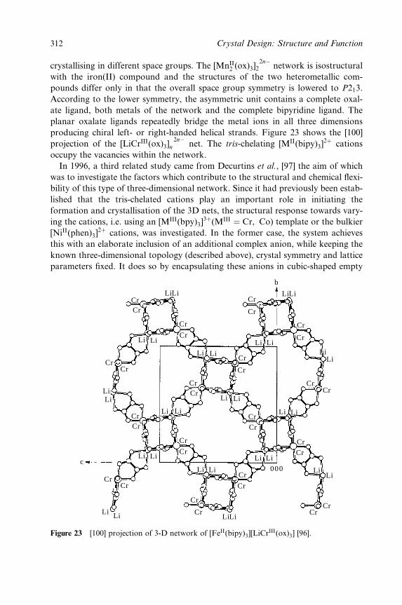
crystallising in different space groups. The [MnII2 (ox)3]2
2nÿnetwork is isostructural
with the iron(II) compound and the structures of the two heterometallic com-
pounds differ only in that the overall space group symmetry is lowered to P213.
According to the lower symmetry, the asymmetric unit contains a complete oxal-
ate ligand, both metals of the network and the complete bipyridine ligand. The
planar oxalate ligands repeatedly bridge the metal ions in all three dimensions
producing chiral left- or right-handed helical strands. Figure 23 shows the [100]
projection of the [LiCrIII(ox)3]2nÿ
n net. The tris-chelating [MII(bipy)3]2� cations
occupy the vacancies within the network.
In 1996, a third related study came from Decurtins et al., [97] the aim of which
was to investigate the factors which contribute to the structural and chemical ¯exi-
bility of this type of three-dimensional network. Since it had previously been estab-
lished that the tris-chelated cations play an important role in initiating the
formation and crystallisation of the 3D nets, the structural response towards vary-
ing the cations, i.e. using an [MIII(bpy)3]3�(MIII � Cr, Co) template or the bulkier
[NiII(phen)3]2� cations, was investigated. In the former case, the system achieves
this with an elaborate inclusion of an additional complex anion, while keeping the
known three-dimensional topology (described above), crystal symmetry and lattice
parameters ®xed. It does so by encapsulating these anions in cubic-shaped empty
CrLiLi
Cr
Cr
Cr
Cr
Cr
Cr
Cr
Cr
Cr
Cr
Cr
Cr
Cr
Cr
Cr
Cr
Cr
Cr
Cr
CrCr
Cr
CrCr
Cr
Cr
CrCr
CrCr
Cr
LiLi
Li Li
LiLi
Li
Li
Li
Li
LiLiLi
LiLi
Li
Li
Li
Li
Li
Li Li
LiLiLi Li
LiLi
LiLi
000
b
c
Figure 23 [100] projection of 3-D network of [FeII(bipy)3][LiCrIII(ox)3] [96].
312 Crystal Design: Structure and Function
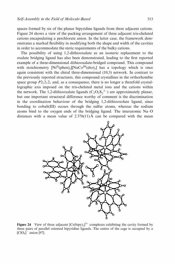
spaces formed by six of the planar bipyridine ligands from three adjacent cations.
Figure 24 shows a view of the packing arrangement of three adjacent tris-chelated
cations encapsulating a perchlorate anion. In the latter case, the framework dem-
onstrates a marked ¯exibility in modifying both the shape and width of the cavities
in order to accommodate the steric requirements of the bulky cations.
The possibility of using 1,2-dithiooxalate as an isosteric replacement to the
oxalate bridging ligand has also been demonstrated, leading to the ®rst reported
example of a three-dimensional dithiooxalate-bridged compound. This compound
with stoichiometry [NiII(phen)3][NaCoIII(dto)3] has a topology which is once
again consistent with the chiral three-dimensional (10,3) network. In contrast to
the previously reported structures, this compound crystallises in the orthorhombic
space group P212121 and, as a consequence, there is no longer a threefold crystal-
lographic axis imposed on the tris-chelated metal ions and the cations within
the network. The 1,2-dithiooxalate ligands (C2O2S2ÿ
2 ) are approximately planar,
but one important structural difference worthy of comment is the discrimination
in the coordination behaviour of the bridging 1,2-dithiooxolate ligand, since
bonding to cobalt(III) occurs through the sulfur atoms, whereas the sodium
atoms bind to the oxygen ends of the bridging ligand. The interatomic Na±O
distances with a mean value of 2.376(11) AÊ can be compared with the mean
Figure 24 View of three adjacent [Cr(bipy)3]3� complexes exhibiting the cavity formed by
three pairs of parallel oriented bipyridine ligands. The centre of the cage is occupied by a[ClO4]
ÿ anion [97].
Self-Assembly in the Field of Molecule-Based 313
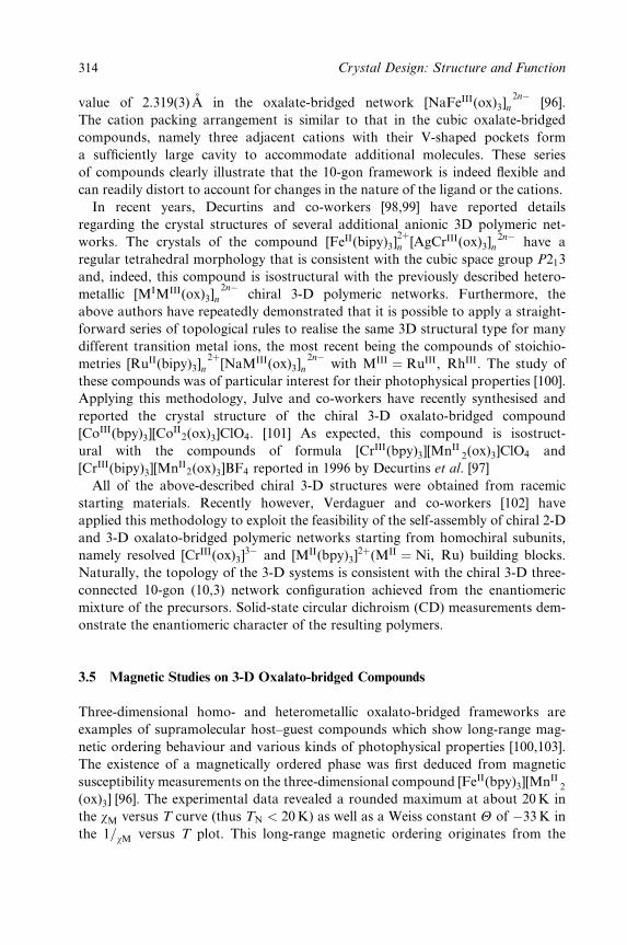
value of 2.319(3)AÊ in the oxalate-bridged network [NaFeIII(ox)3]2nÿ
n [96].
The cation packing arrangement is similar to that in the cubic oxalate-bridged
compounds, namely three adjacent cations with their V-shaped pockets form
a suf®ciently large cavity to accommodate additional molecules. These series
of compounds clearly illustrate that the 10-gon framework is indeed ¯exible and
can readily distort to account for changes in the nature of the ligand or the cations.
In recent years, Decurtins and co-workers [98,99] have reported details
regarding the crystal structures of several additional anionic 3D polymeric net-
works. The crystals of the compound [FeII(bipy)3]2�n [AgCrIII(ox)3]
2nÿn have a
regular tetrahedral morphology that is consistent with the cubic space group P213
and, indeed, this compound is isostructural with the previously described hetero-
metallic [MIMIII(ox)3]2nÿ
n chiral 3-D polymeric networks. Furthermore, the
above authors have repeatedly demonstrated that it is possible to apply a straight-
forward series of topological rules to realise the same 3D structural type for many
different transition metal ions, the most recent being the compounds of stoichio-
metries [RuII(bipy)3]2�
n [NaMIII(ox)3]2nÿ
n with MIII � RuIII, RhIII. The study of
these compounds was of particular interest for their photophysical properties [100].
Applying this methodology, Julve and co-workers have recently synthesised and
reported the crystal structure of the chiral 3-D oxalato-bridged compound
[CoIII(bpy)3][CoII2(ox)3]ClO4. [101] As expected, this compound is isostruct-
ural with the compounds of formula [CrIII(bpy)3][MnII2(ox)3]ClO4 and
[CrIII(bipy)3][MnII2(ox)3]BF4 reported in 1996 by Decurtins et al. [97]
All of the above-described chiral 3-D structures were obtained from racemic
starting materials. Recently however, Verdaguer and co-workers [102] have
applied this methodology to exploit the feasibility of the self-assembly of chiral 2-D
and 3-D oxalato-bridged polymeric networks starting from homochiral subunits,
namely resolved [CrIII(ox)3]3ÿ and [MII(bpy)3]
2�(MII � Ni, Ru) building blocks.
Naturally, the topology of the 3-D systems is consistent with the chiral 3-D three-
connected 10-gon (10,3) network con®guration achieved from the enantiomeric
mixture of the precursors. Solid-state circular dichroism (CD) measurements dem-
onstrate the enantiomeric character of the resulting polymers.
3.5 Magnetic Studies on 3-D Oxalato-bridged Compounds
Three-dimensional homo- and heterometallic oxalato-bridged frameworks are
examples of supramolecular host±guest compounds which show long-range mag-
netic ordering behaviour and various kinds of photophysical properties [100,103].
The existence of a magnetically ordered phase was ®rst deduced from magnetic
susceptibility measurements on the three-dimensional compound [FeII(bpy)3][MnII2
(ox)3] [96]. The experimental data revealed a rounded maximum at about 20 K in
the wM versus T curve (thus TN < 20 K) as well as a Weiss constant Y of ÿ33K in
the 1=wM versus T plot. This long-range magnetic ordering originates from the
314 Crystal Design: Structure and Function

exchange interactions between neighbouring MnII ions, mediated by the bridging
oxalate ligands. This compound was the ®rst three-dimensional oxalato network
for which the magnetic structure could be solved [104]. Neutron diffraction experi-
ments were performed on a polycrystalline sample in the temperature range 30±
1.8 K. As expected, the appearance of magnetic neutron intensities due to the
long-range antiferromagnetic ordering of the spins of the Mn(II) ions was detected.
Figure 25 depicts the pattern of the magnetic structure with the 3-D managane-
se(II) network. Despite the three-dimensional helical character of the framework
structure incorporating the magnetic ions, a two-sub-lattice antiferromagnetic
spin arrangement has been proved, hence no helimagnetic structure was apparent
and this behaviour is in accordance with the typical isotropic character of the
Heisenberg Mn(II) ion.
Magnetic studies on the isostructural three-dimensional networks with stoichio-
metries [CoIII(bpy)3][CoII2 (ox)3]ClO4 (1) and [MII(bpy)3][CoII
2 (ox)3] [MII � Fe (2)
and Ni (3)], recently carried out by Julve et al. [101], show the occurrence of a
weak ferromagnetism at low temperatures for compounds 1 (Tc � 9:0K) and 2
(Tc � 6:5K), whereas no magnetic ordering was observed for compound 3. This
magnetic ordering at very low temperatures is attributed to the spin canting of the
magnetic moments of the metal ions in the chiral three-dimensional oxalate-
bridged cobalt(II) net. These results also suggest that the magnetic ordering of the
three-dimensional [CoII2(ox)3]
2nÿn anionic framework is strongly dependent on
the size and diamagnetic or paramagnetic character of the tris-chelated counter
ions used to achieve the electroneutrality. In this report, the in¯uence of the size
of the [MII=III(bpy)3]2�=3� complex on the spin canted magnetic structure was also
discussed, but further work is needed to investigate these ideas in greater detail.
++
+
++++
+
+
+
+
+
+
− − −
−
−
−−
−
−
− −
−
+
+ +
−
−−
Figure 25 Scheme of antiferromagnetic collinear con®guration of the magnetic momentsoriginating from the Mn(II) ions, which constitute the chiral 3-D network compound [104].
Self-Assembly in the Field of Molecule-Based 315
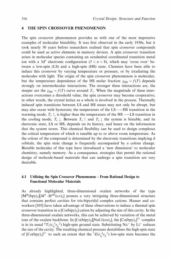
4 THE SPIN CROSSOVER PHENOMENON
The spin crossover phenomenon provides us with one of the most impressive
examples of molecular bistability. It was ®rst observed in the early 1930s, but it
took nearly 50 years before researchers realised that spin crossover compounds
could be used as active elements in memory devices. A spin crossover transition
arises in molecular species containing an octahedral coordinated transition metal
ion with a 3dn electronic con®guration (3 < n < 8), which may `cross over' be-
tween a low-spin (LS) and a high-spin (HS) state. Chemists have been able to
induce this crossover by varying temperature or pressure, or by irradiating the
molecules with light. The origin of the spin crossover phenomenon is molecular,
but the temperature dependence of the HS molar fraction wHS � f (T) depends
strongly on intermolecular interactions. The stronger these interactions are, the
steeper are the wHS � f (T) curve around T1. When the magnitude of these inter-
actions overcomes a threshold value, the spin crossover may become cooperative;
in other words, the crystal lattice as a whole is involved in the process. Thermally
induced spin transitions between LS and HS states may not only be abrupt, but
may also occur with hysteresis; the temperature of the LSÿ!HS transition in the
warming mode, Tc ", is higher than the temperature of the HSÿ!LS transition in
the cooling mode, Tc #. Between Tc " and Tc # the system is bistable, and its
electronic state, LS or HS, depends on its history, and hence on the information
that the system stores. This chemical ¯exibility can be used to design complexes
the critical temperature of which is tunable up to or above room temperature. As
the colour of the compound is determined by the electronic transitions implying d
orbitals, the spin state change is frequently accompanied by a colour change.
Bistable molecules of this type have introduced a `new dimension' to molecular
chemistry, namely memory. As a consequence, strategies that permit the rational
design of molecule-based materials that can undergo a spin transition are very
desirable.
4.1 Utilising the Spin Crossover Phenomenon ± From Rational Design to
Functional Molecular Materials
As already highlighted, three-dimensional oxalate networks of the type
[MII(bpy)3][MI±MIII (ox)3] possess a very intriguing three-dimensional structure
that contains perfect cavities for tris-bipyridyl complex cations. Hauser and co-
workers [105] have taken advantage of these observations to induce a thermal spin
crossover transition in a [Co(bipy)3] cation by adjusting the size of this cavity. In the
three-dimensional oxalate networks, this can be achieved by variation of the metal
ions of the oxalate backbone. In [Co(bipy)3][NaCr(ox)3], the [Co(bpy)3]2� complex
is in its usual 4T1(t5
2ge 2g ) high-spin ground state. Substituting Na� by Li� reduces
the size of the cavity. The resulting chemical pressure destabilises the high-spin state
of [Co(bpy)3]2� to such an extent that the 2E(t 6
2ge 1g ) low-spin state becomes the
316 Crystal Design: Structure and Function
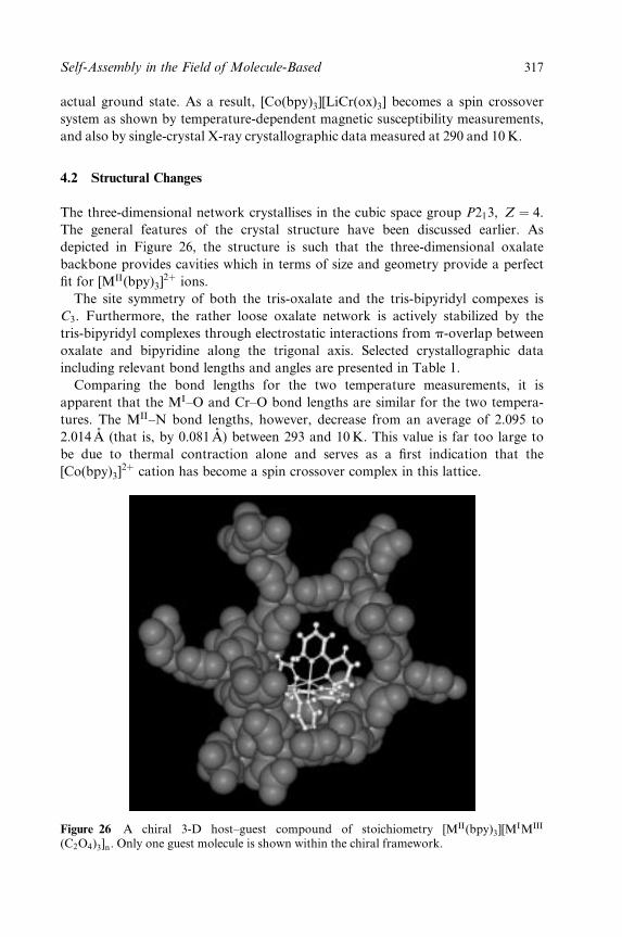
actual ground state. As a result, [Co(bpy)3][LiCr(ox)3] becomes a spin crossover
system as shown by temperature-dependent magnetic susceptibility measurements,
and also by single-crystal X-ray crystallographic data measured at 290 and 10 K.
4.2 Structural Changes
The three-dimensional network crystallises in the cubic space group P213, Z � 4.
The general features of the crystal structure have been discussed earlier. As
depicted in Figure 26, the structure is such that the three-dimensional oxalate
backbone provides cavities which in terms of size and geometry provide a perfect
®t for [MII(bpy)3]2� ions.
The site symmetry of both the tris-oxalate and the tris-bipyridyl compexes is
C3. Furthermore, the rather loose oxalate network is actively stabilized by the
tris-bipyridyl complexes through electrostatic interactions from p-overlap between
oxalate and bipyridine along the trigonal axis. Selected crystallographic data
including relevant bond lengths and angles are presented in Table 1.
Comparing the bond lengths for the two temperature measurements, it is
apparent that the MI±O and Cr±O bond lengths are similar for the two tempera-
tures. The MII±N bond lengths, however, decrease from an average of 2.095 to
2.014 AÊ (that is, by 0.081 AÊ ) between 293 and 10 K. This value is far too large to
be due to thermal contraction alone and serves as a ®rst indication that the
[Co(bpy)3]2� cation has become a spin crossover complex in this lattice.
Figure 26 A chiral 3-D host±guest compound of stoichiometry [MII(bpy)3][MIMIII
(C2O4)3]n. Only one guest molecule is shown within the chiral framework.
Self-Assembly in the Field of Molecule-Based 317
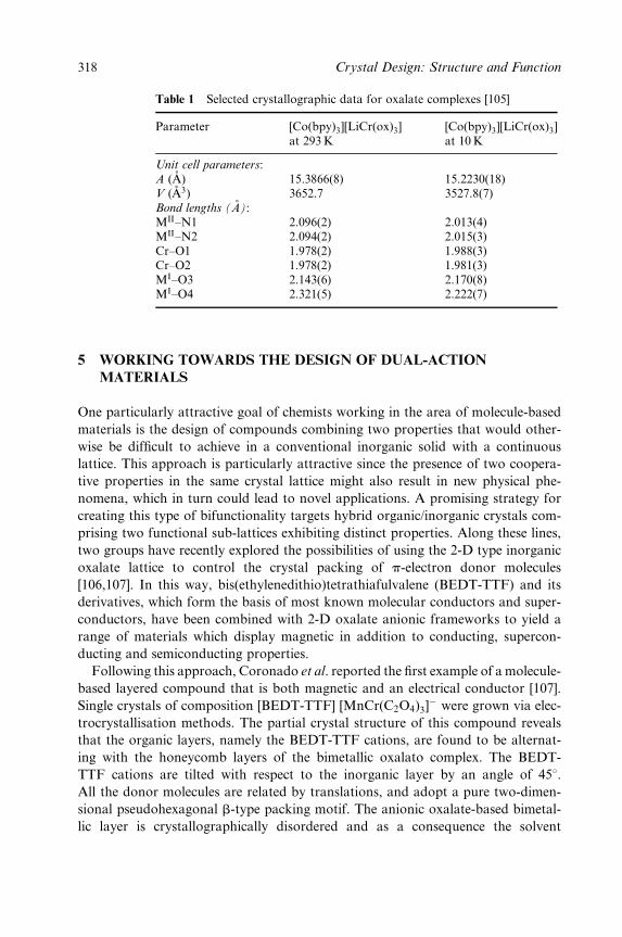
Table 1 Selected crystallographic data for oxalate complexes [105]
Parameter [Co(bpy)3][LiCr(ox)3]at 293 K
[Co(bpy)3][LiCr(ox)3]at 10 K
Unit cell parameters:A (AÊ ) 15.3866(8) 15.2230(18)V ( ÊA3) 3652.7 3527.8(7)Bond lengths (AÊ ):MII±N1 2.096(2) 2.013(4)MII±N2 2.094(2) 2.015(3)Cr±O1 1.978(2) 1.988(3)Cr±O2 1.978(2) 1.981(3)MI±O3 2.143(6) 2.170(8)MI±O4 2.321(5) 2.222(7)
5 WORKING TOWARDS THE DESIGN OF DUAL-ACTION
MATERIALS
One particularly attractive goal of chemists working in the area of molecule-based
materials is the design of compounds combining two properties that would other-
wise be dif®cult to achieve in a conventional inorganic solid with a continuous
lattice. This approach is particularly attractive since the presence of two coopera-
tive properties in the same crystal lattice might also result in new physical phe-
nomena, which in turn could lead to novel applications. A promising strategy for
creating this type of bifunctionality targets hybrid organic/inorganic crystals com-
prising two functional sub-lattices exhibiting distinct properties. Along these lines,
two groups have recently explored the possibilities of using the 2-D type inorganic
oxalate lattice to control the crystal packing of p-electron donor molecules
[106,107]. In this way, bis(ethylenedithio)tetrathiafulvalene (BEDT-TTF) and its
derivatives, which form the basis of most known molecular conductors and super-
conductors, have been combined with 2-D oxalate anionic frameworks to yield a
range of materials which display magnetic in addition to conducting, supercon-
ducting and semiconducting properties.
Following this approach, Coronado et al. reported the ®rst example of a molecule-
based layered compound that is both magnetic and an electrical conductor [107].
Single crystals of composition [BEDT-TTF] [MnCr(C2O4)3]ÿ were grown via elec-
trocrystallisation methods. The partial crystal structure of this compound reveals
that the organic layers, namely the BEDT-TTF cations, are found to be alternat-
ing with the honeycomb layers of the bimetallic oxalato complex. The BEDT-
TTF cations are tilted with respect to the inorganic layer by an angle of 458.All the donor molecules are related by translations, and adopt a pure two-dimen-
sional pseudohexagonal b-type packing motif. The anionic oxalate-based bimetal-
lic layer is crystallographically disordered and as a consequence the solvent
318 Crystal Design: Structure and Function
molecules could not be located. Studies have shown that this compound is metal-
lic down to 4K and is ferromagnetic below 5.5 K. There is, however, no evident
interplay between the two sub-lattices (ferromagnetic and conducting), which
means that from an electronic point of view, the two lattices are quasi-independ-
ent. Nevertheless, these advances indicate that the design of molecule-based ma-
terials with dual properties is bordering on the horizon. Consequently, one of the
major challenges still to be realised in this ®eld is the design of hybrid materials
for which there is an interplay between at least two functional sub-lattices.
6 MAGNETISM ± HISTORICAL OVERVIEW AND FUTURE
OUTLOOK
For more than 2000 years, human fascination with magnets has been historically
recorded. Around the eleventh century, the Chinese found that a steel needle
stroked with `lodestone' (Fe3O4) became magnetic and, furthermore, when this
needle was freely suspended, it pointed north±south. Hence the magnetic compass
was invented and its discovery soon spread to Europe. Indeed, Columbus made
good use of this technology when he made his famous voyage across the Atlantic
Ocean. At several points in history the ®eld of magnetism has experienced a
revival, the ®rst of which came in the seventeenth century when William Gilbert,
physician to Queen Elizabeth I of England, proposed that the Earth itself was a
magnet, with its magnetic poles some distance away from its geographic poles.
Gilbert's initial experiments and observations regarding the magnetic behaviour
of iron resulted in the preparation of the ®rst arti®cial magnet. Since these initial
discoveries, the study and subsequent exploitation of magnets and magnetism
have continued. To date, two broad uses of magnets exist, namely (i) permanent
or `hard' magnets, which produce an external magnetic ®eld that in turn produces
a force on either other magnets or on an electric current, and (ii) nonpermanent
of `soft' magnets, which guide or de¯ect magnetic ®elds and have large magnetic
moments in response to small electric currents. With applications ranging from
wristwatches to industrial motors, magnetic products impact all sectors of our
economy. The global market for the production of magnetic materials is worth
billions of dollars and was estimated in 2000 to be growing at an annual rate of
10% [1]. As a consequence, magnetic phenomena continue to be studied by many
research groups worldwide.
Although discovered less than two decades ago, molecule-based magnets are a
broad emerging class of magnetic materials that expand the materials properties
typically associated with magnets to include low density, transparency, electrical
insulation and low-temperature fabrication. Essentially, all of the common mag-
netic phenomena associated with conventional transition metal- and rare earth-
based magnets can be found in molecule-based magnets. Although this ®eld is still
in its infancy on the magnetism time-scale, magnets with ordering temperatures
Self-Assembly in the Field of Molecule-Based 319
exceeding room temperature, very high and very low coercivities and substantial
remnant and saturation magnetizations have been achieved. In addition, new
interesting phenomena such as spin crossover and photomagnetism have been dis-
covered. The advent of molecule-based magnets offers new processing opportun-
ities, and the discovery and development of new improved magnetic materials
continues to be a major aim at the forefront of modern materials chemistry. In
this chapter we have looked in detail at two families of molecule-based magnets,
namely cyanometalates and transition metal oxalates. Our aim has been
to demonstrate how suitable molecular building blocks combined with a rational
synthetic approach can be successfully applied to engineer new classes of
molecule-based magnets. Given the rapid growth in this ®eld, it is clear that we can
look forward to new advances in this multidisciplinary area of solid-state chemistry
as magnetism continues its renaissance well into the twenty-®rst century.
REFERENCES
1. J. S. Miller, Inorg. Chem., 2000, 39, 4392.2. D. Braga, J. Chem. Soc., Dalton Trans., 2000, 3705.3. J. -M. Lehn, Supramolecular Chemistry: Concepts and Perspectives, 1995, VCH,
Weinheim.4. R. Robson, Comprehensive Supramolecular Chemistry, 1997, Vol. 6, p.733. Pergamon
Press, Oxford.5. M. Eddaoudi, D. B. Moler, H. Chen, T. M. Reinke, M. O'Keeffe, O.M. Yaghi, Acc.
Chem. Res., 2001, 34, 319.6. F. M. Tabellion, S. R. Siedel, A. M. Arif, P. Stang, J. Am. Chem. Soc., 2001, 123,
11982.7. M. Verdaguer, Science, 1996, 272, 698.8. J. S. Miller, A. J. Epstein, MRS Bull., 2000, 21.9. O. Kahn, Molecular Magnetism, 1993, Wiley-VCH: Weinheim.
10. H. H. Wickman, A. M. Trozzolo, H. J. Williams, G. W. Hull, F. R. Merrett, Phys.
Rev., 1967, 155, 563.11. H. H. Wickman, J.Chem. Phys., 1972, 56, 976.12. G. C. DeFohs, F. Palacio, C. J. O'Connor, S. N. Bhaatia, R. L. Carlin, J. Am. Chem.
Soc., 1977, 99, 8314.13. N. Arai, M. Sorai, H. Suga, S. Seki, J. Phys. Chem. Solids, 1977, 36, 1231.14. J. H. Helms, W. E. Hat®eld, M. J. Kwiecien, W. M. Reiff, J. Chem. Phys., 1986, 84,
3993.15. R. Bumel, J. Casabo, J. Pons, D. E. Carnegie Jr, R. L. Carlin, Physica, 1985, 132B,
185.16. O. Kahn, Struct. Bonding (Berlin), 1987, 68, 89.17. O. Kahn, Angew. Chem., Int. Ed. Engl., 1985, 24, 834.18. S. Decurtins, Chimia, 1988, 10, 539.19. K. R. Dunbar, R. A. Heintz, Prog. Inorg. Chem., 1997, 45, 283.20. M. Verdaguer, A. Bleuzen, V. Marvaud, J. Vaissermann, M. Seuleiman, C. Des-
planches, A. Scuiller, C. Train, R. Garde, G. Gelly, C. Lamenech, I. Rosenman,P. Veillet, C. Cartier, F. Villain, Coord. Chem. Rev., 1999, 190±192, 1023.
21. M. Verdaguer, Polyhedron, 2001, 20, 1115.AQ2
320 Crystal Design: Structure and Function
22. M. Ohba, H. Okawa, Coord. Chem. Rev., 2000, 198, 313.23. Misc. Berolinensia Incrementum Sci. Berlin, 1710, 1, 337.24. J. F. Keggin, J. F. Miles, Nature (London), 1936, 137, 577.25. A. Ludi, H-U. GuÈdel, Struct. Bonding (Berlin), 1973, 14, 1.26. J. H. Buser, G. Ron, A. Ludi, P. Engel, J. Chem. Soc., Dalton Trans., 1974, 2473.27. O. Kahn, Nature (London), 1995, 373, 667.28. A. N. Holden, B. T. Matthias, P. W. Anderson, H. W. Lewis, Phys. Rev., 1956, 102,
1463.29. R. M. Bozworth, H. J. Williams, D. E. Walsh, Phys. Rev., 1956, 103, 572.30. R. Klenze, B. Kanellopoulus, G. Trageser, H. H. Eysel, J. Chem. Phys., 1980, 72, 5819.31. W. D. Geiebler, D. Babel, Z. Naturforsch., Teil B, 1982, 87, 832.32. D. Babel, Comments Inorg. Chem., 1986, 5, 285.33. S. Ferley, T. Mallah, R. OuaheÁs, P. Veillet, M. Verdaguer, Nature (London), 1995, 378,
701.34. O. Hatlevic, W. E. Buschmann, J. Zhang, J. L. Manson, J. S. Miller, Adv. Mater., 1999,
11, 914.35. S. Holmes, G. Girolami, J. Am. Chem. Soc., 1999, 121, 5593.36. P. Franz, H. Stoeckli-Evans, S. Decurtins, Angew. Chem., Int. Ed. Engl., in preparation.37. O. Sato, T. Iyoda, A. Fujishima, K. Hashimoto, Science, 1996, 272, 704.38. M. Ohba, N. Maruono, H. Okawa, T. Enoki, J. M. Latour, J. Am. Chem. Soc., 1997,
119, 1011.39. T. Mallah, C. Auberger, M. Verdaguer, P. Veillet, J. Chem. Soc., Chem. Commun.,
1995, 61.40. M. Ohba, N. Maruono, H. Okawa, T. Enoki, J. M. Latour, J. Am. Chem. Soc., 1994,
116, 11566.41. R. J. Parker, D. C. R. Hockless, B. Moubaraki, K. S. Murray, L. Spicia, J. Chem. Soc.,
Chem. Commun., 1996, 2789.42. H. Okawa, M. Ohba, in M. M. Turnbull, T. Sugimoto, L. K. Thompson (Eds), Mol-
ecule-Based Magnetic Materials, ACS Symposium Series No. 644. American ChemicalSociety: Washington, DC, 1966, p.319.
43. M. Ohba, N. Uski, N. Fukita, H. Okawa, Inorg. Chem., 1998, 37, 3349.44. N. Re, E. Gallo, C. Floriani, H. Miyasaka, N. Matsumoto, Inorg. Chem., 1996, 35,
6004.45. E. Colacio, J. M. Dominguez-Vera, M. Ghazi, R. KivekaÈs, M. Klinga, J. M. Moreno,
J. Chem. Soc., Chem. Commun., 1998, 1071.46. E. Colacio, M. Ghazi, H. Stoeckli-Evans, F. Lloret, J. M. Moreno, C. PeÂrez, Inorg.
Chem., 2001, 40, 4876.47. S. Ferlay, T. Mallah, J. Vaissermann, F. Bartolome, P. Veillet, M. Verdaguer, J. Chem.
Soc., Chem. Commun., 1996, 2482.48. M. Ohba, H. Okawa, T. Ito, A. Ohto, J. Chem. Soc., Chem. Commun., 1995, 1545.49. M. Ohba, H. Okawa, Mol. Cryst. Liq. Cryst., 1996, 286, 101.50. M. Ohba, N. Fukita, H. Okawa, Y. Hashimoto, J. Am. Chem. Soc., 1997, 119, 1011.51. H. Z. Kou, W. M. Bu, D. Z. Liao, Z. H. Jiang, S. P. Yan, Y. G. Fan, H. G. Wang,
J. Chem. Soc., Dalton. Trans., 1998, 4161.52. H. Miyasaka, N. Matsumoto, N. Re, E. Gallo, C. Floriani, Angew. Chem., Int. Ed.
Engl., 1995, 34, 1446.53. H. Miyasaka, N. Matsumoto, H. Okawa, N. Re, E, Gallo, C. Floriani, J. Am. Chem.,
Soc., 1996, 118, 981.54. H. Miyasaka, H. Ieda, N. Matsumoto, N. Re, E. Gallo, C. Floriani, Inorg. Chem.,
1988, 37, 255.55. H. Miyasaka, H. Okawa, A. Miyazaki, T. Enoki, Inorg. Chem., 1988, 37, 4878.
Self-Assembly in the Field of Molecule-Based 321
56. N. Fukita, M. Ohba, H. Okawa, K. Matsuda, H. Iwnura, Inorg. Chem., 1998, 37, 842.57. M. S. El. Fallah, E. Rentschler, A. Caneschi, R. Sessoli, D. Gatteschi, Angew. Chem.
Int. Ed. Engl., 1996, 35, 1947.58. M. Ohba, N. Usuki, N. Fukita, H. Okawa, Angew. Chem., Int. Ed. Engl., 1995, 34,
1446.59. N. Usuki, M. Yamada, M. Ohba, H. Okawa, Polyhedron, 2001, 159, 328.60. J. A. Smith, J. R. G. MascaroÂs, R. CleÂrac, J.-S. Sun, X. Ouyang, K. R. Dunbar,
Polyhedron, 2001, 20, 1727.61. T. Mallah, C. Auberger, M. Verdaguer, P. Veillet, J. Chem. Soc., Chem. Commun.,
1995, 61.62. A. Scuiller,, T. Mallah, J. Vaissermann, F. BartolomeÂ, P. Veillet, M, Verdaguer,
J. Chem. Soc., Chem. Commun., 1996, 2481.63. J. Larionova, J. Sanchiz, S. Golhen, L. Ouahab, O. Kahn, J. Chem. Soc., Chem.
Commun., 1998, 953.64. J. Larionova, O. Kahn , S. Golhen, L. Ouahab, R. CleÂrac, Inorg. Chem., 1999, 38,
3621.65. J. Larionova, R. CleÂrac, J. Sanchiz, O. Kahn S. Golhen, L. Ouahab, Inorg. Chem.,
1999, 38, 3621.66. O. Kahn, J. Larionova, L. Ouahab, J. Chem. Soc., Chem. Commun., 1999, 945.67. A. K. Sra, M. Andruh, O. Kahn, S. Golhen, L. Ouahab, J. V. Yakhmi, Angew.
Chem., Int. Ed. Engl., 1999, 38, 2606.68. M. Pilkington, S. Decurtins, Chimia, 2000, 54, 593.69. G. Rombaut, S. Golhen, L. Ouahab, C. MathionieÁre, O. Kahn, J. Chem. Soc., Dalton.
Trans., 2000, 3609.70. J. Larionova, M. Gross, M. Pilkington, H.-P. Andres, H. Stoeckli-Evans, H. U.
GuÈdel, S. Decurtins, Angew. Chem., Int. Ed. Engl., 2000, 39, 1605.71. Z. J. Zhong, H. Seino, Y. Mizobe, M. Hidai, A. Fujishima, S. Ohkoshi, K. Hashi-
moto, J. Am. Chem. Soc., 2000, 122, 2952.72. F. Bonadio, M. Gross, H. Stoeckli-Evans, S. Decurtins, Inorg. Chem., 2002, 22, 5891.73. M. Pilkington, M. Gross, L. Gilby, S. Decurtins, in preparation.74. P. Franz, M. Pilkington, S. Decurtins, M. Verdaguer, K. Hashimoto, Inorg. Chem., in
preparation.75. M. Pilkington, M. Biner, S. Decurtins, H. Stoeckli-Evans, unpublished results.76. Z. J. Zhong, H. Seino, Y. Mizobe, M. Hidai, M. Verdaguer, S-I. Ohkoshi, K. Hashi-
moto, Inorg. Chem., 2000, 39, 5095.77. A. K. Sra, G. Rombaut, F. LahiteÃte, S. Golhen, L, Ouahab, C. MathonieÁre, J. V.
Yakhmi, O. Kahn, New J. Chem., 2000, 24, 871.78. G. Rombaut, M. Verelst, S. Golhen, L. Ouahab, C. MathonieÁre, O. Kahn, Inorg.
Chem., 2001, 40, 1151.79. J. J. Girerd, O. Kahn, M. Verdaguer, Inorg. Chem., 1980, 19, 274.80. R. Pellaux, H. W. Schmalle, R. Huber, P. Fischer, T. Hauss, B. Ouladdiaf, S. Decur-
tins, Inorg. Chem., 1997, 36, 2301.81. H. Oshio, U. Nagashima, Inorg. Chem., 1992, 31, 3295.82. L. O. Atovmyan, G. V. Shilov, R. N. Lyubovskaya, E. I. Zhilyaeva, N. S. Ovanesyan,
S. I. Pirumova, I. G. Gusakovskaya, JETP Lett., 1993, 58, 766.83. S. Decurtins, H. W. Schmalle, H. R. Oswald, A. Linden, J. Ensling, P. GuÈtlich,
A. Hauser, Inorg. Chim. Acta, 1994, 216, 65.84. S. Decurtins, H. W. Schmalle, P. Schneuwly, H. R. Oswald, Inorg. Chem., 1993, 32,
1888.85. S. G. Carling, C. MathonieÁre, P. Day, K. M. A. Malik, S. J. Coles, M. B. Hursthouse,
J. Chem. Soc., Dalton Trans., 1996, 1839.
322 Crystal Design: Structure and Function
86. M. Clemente-LeÂon, E. Coronado, J. Galan-Mascaros, C. Gomez-Garcia, J. Chem.
Soc., Chem. Commun., 1997, 1727.87. E. Coronado, J. Galan-Mascaros, C. Gomez-Garcia, J. Ensling, P. GuÈtlich, Chem.
Eur. J., 2000, 6, 552.88. C. J. Nuttall, C. Bellitto, P. Day, J. Chem. Soc., Chem. Commun., 1995, 1513.89. C. MathonieÁre, S. G. Carling, D. Yusheng, P. Day, J. Chem. Soc., Chem. Commun.
1994, 1551.90. C. MathonieÁre, C. J. Nuttall, S. G. Carling, P. Day, Inorg. Chem., 1996, 35, 1201.91. H. Tamaki, M. Mitsumi, K. Nakamura, N. Matsumoto, S. Kida, H. Okawa, S. Ijima,
Chem. Lett., 1992, 1975.92. H. Tamaki, Z. J. Zhong, N. Matsumoto, S. Kida, M. Koikawa, N. Achiwa,
Y. Hashimoto, H. Okawa, J. Am. Chem. Soc., 1992, 114, 6974.93. C. J. Nuttall, P. Day, Chem. Mater., 1998, 10, 3050.94. L. O. Atovmyan, G. V. Shilov, N. S. Ovanesyan, A. A. Pyalling, R. N. Lyubovskaya,
E. I. Zhilyaeva, Y. G. Morozov, Synth. Met., 1995, 71, 1809.95. K. R. Butler, M. R. Snow, J. Chem. Soc. A, 1971, 565.96. S. Decurtins, H. W. Schmalle, P. Schneuwly, J. Ensling, P. GuÈtlich, J. Am. Chem.
Soc., 1994, 116, 9521.97. S. Decurtins, H. W. Schmalle, R. Pellaux, P. Schneuwly, A. Hauser, Inorg. Chem.,
1996, 35, 1451.98. H. W. Schmalle, R. Pellaux, S. Decurtins, Z. Kristallogr., 1996, 211, 533.99. R. Pellaux, S. Decurtins, H. W. Schmalle, Acta Crystallogr, Sect. C, 1999, 55, 1057.
100. M. E. von Arx, L. van Pieterson, E. Burattini, A. Hauser, R. Pellaux, S. Decurtins,J. Phys. Chem. A, 2000, 104±105, 883.
101. M. Hernandez-Molina, F. Lloret, C. Ruiz, M. Julve, Inorg. Chem., 1998, 37, 4031.102. R. AndreÂs, M. Gruselle, B. MaleÂzieux, M. Verdaguer, J. Vaissermann, Inorg. Chem.,
1999, 38, 4637.103. M. E. von Arx, A. Hauser, H. Riesen, R. Pellaux, S. Decurtins, Phys. Rev. B, 1996,
54, 1500.104. S. Decurtins, H. W. Schmalle, R. Pellaux, R. Huber, P. Fischer, B. Ouladdiaf, Adv.
Mater., 1996, 8, 647.105. R. Sieber, S. Decurtins, H. Stoeckli-Evans, C. Wilson, D. Yu®t, J. A. K. Howard,
S. C. Capelli, A. Hauser, Chem. Eur. J., 2000, 2, 361.106. S. Rashid, S. S. Turner, P. Day, J. A. K. Howard, P. Guionneau, E. J. L. McInnes,
F. E. Mabbs, R. J. H. Clark, S. Firth, T. Biggs, J. Mater. Chem., 2001, 11, 2095.107. E. Coronado, J. R. Galan-MascaroÂs, C. J. Gomez-Garcia, V. Laukhin, Nature
(London), 2000, 408, 447.
Self-Assembly in the Field of Molecule-Based 323
Chapter 8
Polymorphism, CrystalTransformations and Gas±SolidReactions
DARIO BRAGA
University of Bologna, Bologna, Italy
FABRIZIA GREPIONI
University of Sassari, Sassari, Italy
. . . a new way for the atoms of water to stack and lock, to freeze. . . .
It had a melting point of one hundred fourteen point four degrees Fahrenheit. [. . .]
that crystalline form of water, that blue±white gem, that seed of doom called ice-nine.
K. Vonnegut, Cat's Cradle, Penguin Books, London, 1965
1 INTRODUCTION
The controlled preparation and characterization of different crystal forms of the
same substance has become one of the major issues of modern crystal engineering
and solid-state chemistry. Even though the discovery of polymorphs of molecular
crystals or of their diverse solvate forms (pseudo-polymorphs) is often serendipit-
ous, crystal polymorphism can, to some extent, be controlled. The existence of
more than one packing arrangement for the same molecular or ionic compon-
ent(s) could be a major drawback for the purposed bottom-up construction of
functional solids. Rather than attempting a thorough review of the subject, this
Crystal Design: Structure and Function. Volume 7Edited by Gautam R. Desiraju
Copyright 2003 John Wiley & Sons, Ltd.ISBN: 0-470-84333-0
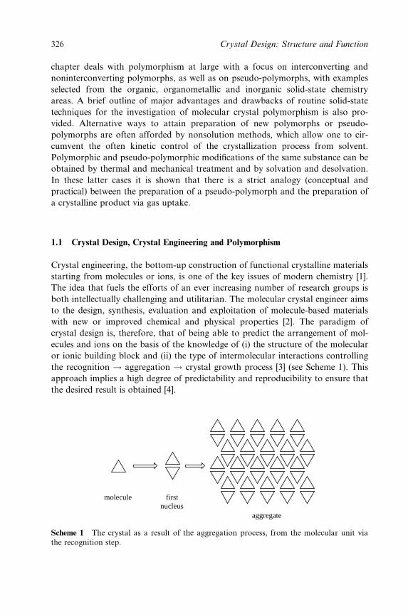
chapter deals with polymorphism at large with a focus on interconverting and
noninterconverting polymorphs, as well as on pseudo-polymorphs, with examples
selected from the organic, organometallic and inorganic solid-state chemistry
areas. A brief outline of major advantages and drawbacks of routine solid-state
techniques for the investigation of molecular crystal polymorphism is also pro-
vided. Alternative ways to attain preparation of new polymorphs or pseudo-
polymorphs are often afforded by nonsolution methods, which allow one to cir-
cumvent the often kinetic control of the crystallization process from solvent.
Polymorphic and pseudo-polymorphic modi®cations of the same substance can be
obtained by thermal and mechanical treatment and by solvation and desolvation.
In these latter cases it is shown that there is a strict analogy (conceptual and
practical) between the preparation of a pseudo-polymorph and the preparation of
a crystalline product via gas uptake.
1.1 Crystal Design, Crystal Engineering and Polymorphism
Crystal engineering, the bottom-up construction of functional crystalline materials
starting from molecules or ions, is one of the key issues of modern chemistry [1].
The idea that fuels the efforts of an ever increasing number of research groups is
both intellectually challenging and utilitarian. The molecular crystal engineer aims
to the design, synthesis, evaluation and exploitation of molecule-based materials
with new or improved chemical and physical properties [2]. The paradigm of
crystal design is, therefore, that of being able to predict the arrangement of mol-
ecules and ions on the basis of the knowledge of (i) the structure of the molecular
or ionic building block and (ii) the type of intermolecular interactions controlling
the recognition ! aggregation ! crystal growth process [3] (see Scheme 1). This
approach implies a high degree of predictability and reproducibility to ensure that
the desired result is obtained [4].
aggregate
firstnucleus
molecule
Scheme 1 The crystal as a result of the aggregation process, from the molecular unit viathe recognition step.
326 Crystal Design: Structure and Function
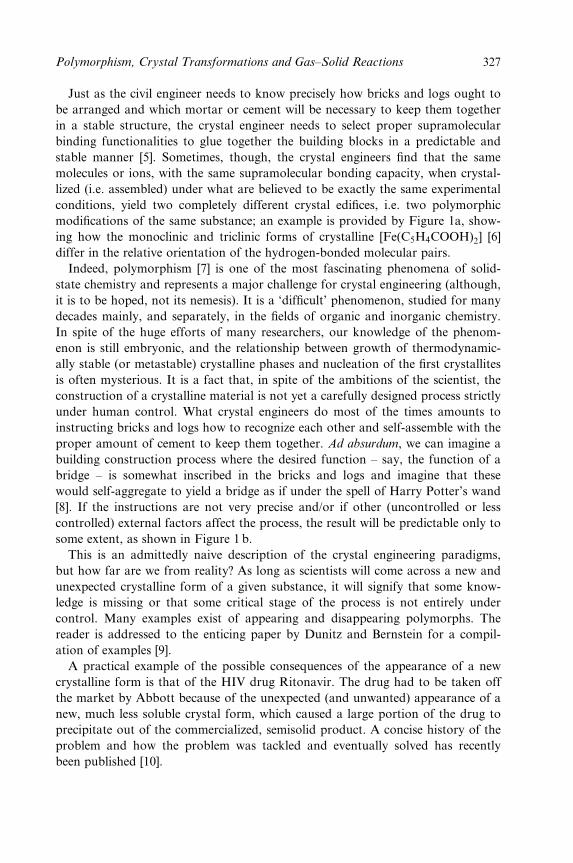
Just as the civil engineer needs to know precisely how bricks and logs ought to
be arranged and which mortar or cement will be necessary to keep them together
in a stable structure, the crystal engineer needs to select proper supramolecular
binding functionalities to glue together the building blocks in a predictable and
stable manner [5]. Sometimes, though, the crystal engineers ®nd that the same
molecules or ions, with the same supramolecular bonding capacity, when crystal-
lized (i.e. assembled) under what are believed to be exactly the same experimental
conditions, yield two completely different crystal edi®ces, i.e. two polymorphic
modi®cations of the same substance; an example is provided by Figure 1a, show-
ing how the monoclinic and triclinic forms of crystalline [Fe(C5H4COOH)2] [6]
differ in the relative orientation of the hydrogen-bonded molecular pairs.
Indeed, polymorphism [7] is one of the most fascinating phenomena of solid-
state chemistry and represents a major challenge for crystal engineering (although,
it is to be hoped, not its nemesis). It is a `dif®cult' phenomenon, studied for many
decades mainly, and separately, in the ®elds of organic and inorganic chemistry.
In spite of the huge efforts of many researchers, our knowledge of the phenom-
enon is still embryonic, and the relationship between growth of thermodynamic-
ally stable (or metastable) crystalline phases and nucleation of the ®rst crystallites
is often mysterious. It is a fact that, in spite of the ambitions of the scientist, the
construction of a crystalline material is not yet a carefully designed process strictly
under human control. What crystal engineers do most of the times amounts to
instructing bricks and logs how to recognize each other and self-assemble with the
proper amount of cement to keep them together. Ad absurdum, we can imagine a
building construction process where the desired function ± say, the function of a
bridge ± is somewhat inscribed in the bricks and logs and imagine that these
would self-aggregate to yield a bridge as if under the spell of Harry Potter's wand
[8]. If the instructions are not very precise and/or if other (uncontrolled or less
controlled) external factors affect the process, the result will be predictable only to
some extent, as shown in Figure 1 b.
This is an admittedly naive description of the crystal engineering paradigms,
but how far are we from reality? As long as scientists will come across a new and
unexpected crystalline form of a given substance, it will signify that some know-
ledge is missing or that some critical stage of the process is not entirely under
control. Many examples exist of appearing and disappearing polymorphs. The
reader is addressed to the enticing paper by Dunitz and Bernstein for a compil-
ation of examples [9].
A practical example of the possible consequences of the appearance of a new
crystalline form is that of the HIV drug Ritonavir. The drug had to be taken off
the market by Abbott because of the unexpected (and unwanted) appearance of a
new, much less soluble crystal form, which caused a large portion of the drug to
precipitate out of the commercialized, semisolid product. A concise history of the
problem and how the problem was tackled and eventually solved has recently
been published [10].
Polymorphism, Crystal Transformations and Gas±Solid Reactions 327
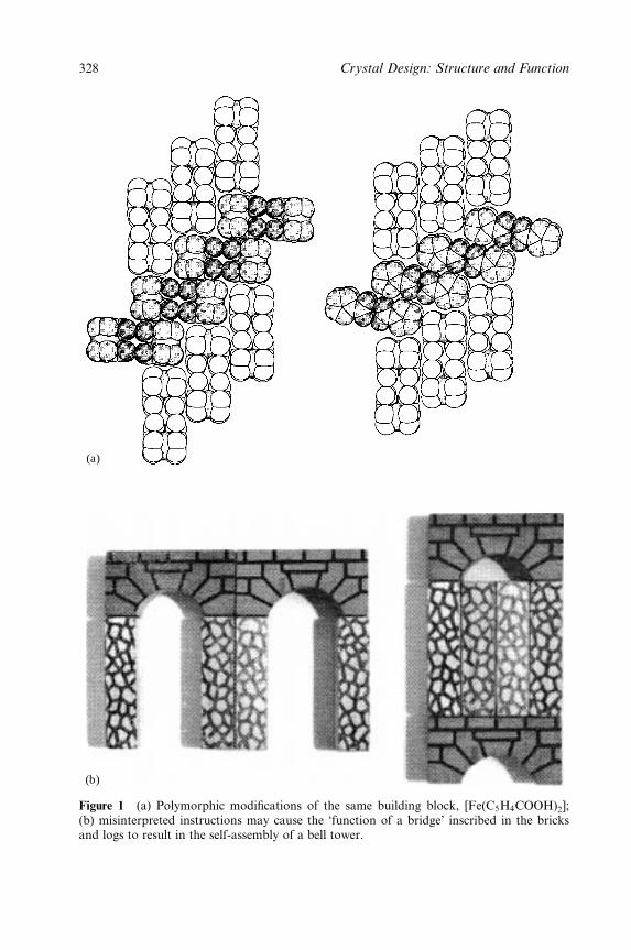
(a)
(b)
Figure 1 (a) Polymorphic modi®cations of the same building block, [Fe(C5H4COOH)2];(b) misinterpreted instructions may cause the `function of a bridge' inscribed in the bricksand logs to result in the self-assembly of a bell tower.
328 Crystal Design: Structure and Function
Polymorphism is very often an unpredictable `happening' of solid-state science
and yet it is not a rare event. Actually, polymorphism should be a very likely
event: the work of many theoretical solid-state scientists [11] has shown that there
is usually a large number of possible arrangements of the same molecules or ions
strictly within a few percent of the enthalpy of the observed crystal structure.
However, while many compounds exist in several crystalline forms, for most sub-
stances only one crystalline form is known. Whether this is due to the simple fact
that, in most cases, crystallographers and synthetic chemists have been satis®ed
with the determination of one molecular structure, thus making the occurrence of
polymorphs an unrecognized, unsought or even undesired event (because a second
molecular structure of the same substance is/was usually considered not worth
publishing), or to some other more subtle structural feature, it is hard to say. It is
a fact, however, that commercially relevant compounds (drugs, pigments, foods,
materials) seem to show a propensity towards the formation of polymorphs.
It is consequential from these considerations that polymorphism occupies an
extraordinarily relevant place in the solid-state sciences. Even the smallest step
ahead in understanding the reasons for polymorphism, and of how to bend it to
our wishes/needs, might represent a quantum leap in structural sciences with
enormous conceptual, practical and economic consequences. One way to tackle
this problem is the computational generation of theoretical crystal structures [11],
which often goes under the epithet of crystal structure prediction. Even though
this is a very important area of research, it will be touched upon only marginally
in this chapter and mainly in connection with experimental results.
This chapter deals with polymorphism in broad terms. The focus will be
mainly, but not exclusively, on crystals formed of neutral molecules or of molecu-
lar ions. Natural inorganic compounds, minerals, clays, etc., and extended cova-
lent solids will not be discussed. Rather than attempting a thorough review of the
subject, we will discuss polymorphism by means of a series of examples selected
from the organic, organometallic and inorganic solid-state chemistry areas. We
shall also look at the most important, routinely available, techniques for the
characterization of polymorphs and of polymorph interconversion. We will then
discuss alternative ways to generate new polymorphic or pseudo-polymorphic
modi®cations of the same substance by `nonsolution' methods, and the last
section will draw an analogy between the formation of pseudo-polymorphs via
gas uptake/release and solid±gas reactivity.
2 POLYMORPHISM, PSEUDO-POLYMORPHISM AND
GAS±SOLID REACTIONS
Even though molecular crystal polymorphs contain exactly the same molecules or
ions, they usually possess different chemical and physical properties such as dens-
ity, diffraction pattern, solid-state spectra, melting point, stability and reactivity.
Polymorphism, Crystal Transformations and Gas±Solid Reactions 329

Many drugs can be obtained in different polymorphic modi®cations. These forms
may possess fundamentally different properties, for instance different rates of
assimilation because of differences in solubility [12]. The enormous economic
implications of this aspect are witnessed, interalia, by the number of patent litiga-
tions involving drug companies. Polymorphs may also show different behaviour
under mechanical stress, with relevant consequences on comminution and
tableting, hence on their processing and marketing [13].
Indeed, pills and tablets are among the commonest forms in which pharmaceut-
ical compounds are distributed. Hence problems associated with solid-state trans-
formations and stability of solid drugs have always had a strong appeal,
particularly for economic reasons. The `Zantac story' has become almost a text-
book example of the commercial implications of polymorphism. Zantac is the
commercial name of ranitidine hydrochloride, an anti-ulcer drug produced by
Glaxo Wellcome. The compound has been crystallized in two different forms,
named polymorphs 1 and 2. Form 2 is Glaxo's commercial form and its patent
ends in 2002, whereas form 1 had been patented by Glaxo earlier. The end of the
patent covering form 1 in 1977 led many ®rms to attempt to enter the market with
the generic product. However, attempts to make form 1 according to the proced-
ure described in the Glaxo Wellcome patent invariably led to crystals of form 2.
The issue led to a series of patent litigations between Glaxo and other companies,
including Novopharm. The reader is directed to Bernstein's book [7] not only for
a thorough account of a number of commercial issues related to drug polymorph-
ism, but also for a complete state of the art overview of the ®eld and for the
historical background.
De®nitions always imply that limitations are imposed on the subject matter. This
is very much true of polymorphism, which spans all areas of chemistry and some of
mineralogy. In the case of molecule-based polymorphs, the safest approach is prob-
ably to consider polymorphic crystal structures as those leading to identical liquid
(whether melt or solution) or vapour states. The de®nition becomes less clear cut in
the cases of solvate species and of amorphous materials. Table 1 provides a basic
glossary of terms that will be used throughout this chapter.
The problem of whether an amorphous material may or may not be considered
a `form' of a solid substance has been discussed [18a]. Many compounds yield
stable noncrystalline phases either as the exclusive product of a crystallization
process, or in a mixture with crystals or as a consequence of the treatment of
otherwise crystalline phases [18]. The fundamental drawback when dealing with
amorphous phases is the dearth of techniques for the thorough characterization of
an amorphous phase or for the discrimination between different amorphous
phases. In general, diffraction techniques are of little help when dealing with
amorphous materials and one has to rely mainly on spectroscopic means (see
below). Clearly, if one takes the ful®lment of Bragg's law as the pre-condition for
the existence of a crystalline phase, and hence for the existence of a molecular
crystal polymorph, amorphous materials are not to be considered.
330 Crystal Design: Structure and Function
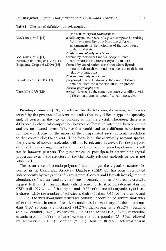
Table 1 Glossary of definitions on polymorphism.
A (molecular) crystal polymorph is:McCrone (1965) [14] a solid crystalline phase of a given compound resulting
from the possibility of at least two differentarrangements of the molecules of that compoundin the solid state
Conformational polymorphs are:McCrone (1965) [14]Bernstein and Hagler (1978) [15]
formed by molecules that can adopt differentconformations in different crystal structures
Braga and Grepioni (2000) [16] formed by coordination complexes where ligandsbound in delocalized bonding modes adopt differentrelative orientations
Concomitant polymorphs are:Bernstein et al. (1999) [17] polymorphic modifications of the same substance
obtained from the same crystallisation processPseudo-polymorphs are:
Threlfall (1995) [12b] crystals formed by the same substance crystallized withdifferent amounts or types of solvent molecules
Pseudo-polymorphs [12b,19], relevant for the following discussion, are charac-
terized by the presence of solvent molecules that may differ in type and quantity
and, of course, in the way of bonding within the crystal. Therefore, there is a
difference in chemical composition between different solvates and between these
and the unsolvated forms. Whether this would lead to a different behaviour in
solution will depend on the nature of the encapsulated guest molecule in relation
to that constituting the solvent. If the focus is on the chemically relevant species,
the presence of solvent molecules will not be relevant; however, for the purposes
of crystal engineering, the solvent molecules present in pseudo-polymorphs will
not be innocent partners. The guest molecules participate in determining crystal
properties, even if the structure of the chemically relevant molecule or ion is not
in¯uenced.
The occurrence of pseudo-polymorphism amongst the crystal structures de-
posited in the Cambridge Structural Database (CSD) [20] has been investigated
independently by two groups of investigators. GoÈrbitz and Hersleth investigated the
abundance of hydrates and solvate forms in organic and metallo-organic crystals,
separately [19a]. It turns out that, with reference to the structures deposited in the
CSD until 1999, 8.1 % of the organic and 10.5 % of the metallo-organic crystals are
hydrates, while the number of solvates is slightly higher, 7.0 % of the organic and
17.3% of the metallo-organic structures contain uncoordinated solvent molecules
other than water. In terms of relative abundance, in organic crystals the most abun-
dant `free' solvents are methanol (14.2 %), dichloromethane (8.52 %), benzene
(8.27 %), ethanol (7.42 %), chloroform (7.36 %) and acetonitrile (7.32 %). In metallo-
organic crystals dichloromethane becomes the most popular (23.47%), followed
by acetonitrile (9.46 %), benzene (9.12%), toluene (8.71 %), tetrahydrofuran
Polymorphism, Crystal Transformations and Gas±Solid Reactions 331
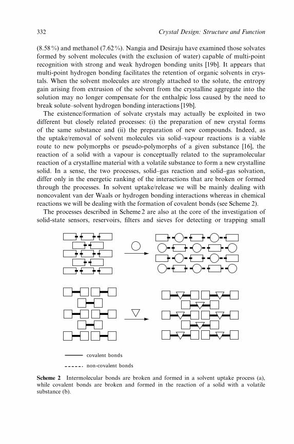
(8.58 %) and methanol (7.62 %). Nangia and Desiraju have examined those solvates
formed by solvent molecules (with the exclusion of water) capable of multi-point
recognition with strong and weak hydrogen bonding units [19b]. It appears that
multi-point hydrogen bonding facilitates the retention of organic solvents in crys-
tals. When the solvent molecules are strongly attached to the solute, the entropy
gain arising from extrusion of the solvent from the crystalline aggregate into the
solution may no longer compensate for the enthalpic loss caused by the need to
break solute±solvent hydrogen bonding interactions [19b].
The existence/formation of solvate crystals may actually be exploited in two
different but closely related processes: (i) the preparation of new crystal forms
of the same substance and (ii) the preparation of new compounds. Indeed, as
the uptake/removal of solvent molecules via solid±vapour reactions is a viable
route to new polymorphs or pseudo-polymorphs of a given substance [16], the
reaction of a solid with a vapour is conceptually related to the supramolecular
reaction of a crystalline material with a volatile substance to form a new crystalline
solid. In a sense, the two processes, solid±gas reaction and solid±gas solvation,
differ only in the energetic ranking of the interactions that are broken or formed
through the processes. In solvent uptake/release we will be mainly dealing with
noncovalent van der Waals or hydrogen bonding interactions whereas in chemical
reactions we will be dealing with the formation of covalent bonds (see Scheme 2).
The processes described in Scheme 2 are also at the core of the investigation of
solid-state sensors, reservoirs, ®lters and sieves for detecting or trapping small
non-covalent bonds
covalent bonds
Scheme 2 Intermolecular bonds are broken and formed in a solvent uptake process (a),while covalent bonds are broken and formed in the reaction of a solid with a volatilesubstance (b).
332 Crystal Design: Structure and Function
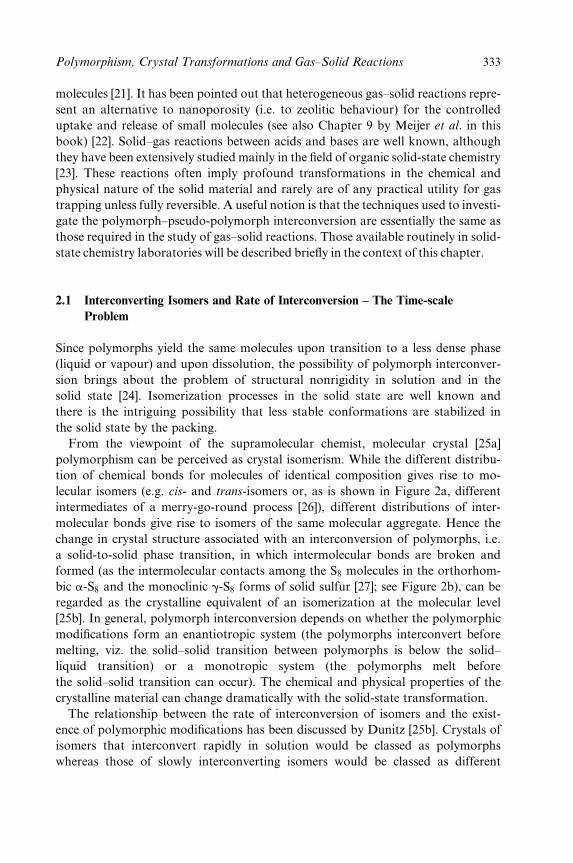
molecules [21]. It has been pointed out that heterogeneous gas±solid reactions repre-
sent an alternative to nanoporosity (i.e. to zeolitic behaviour) for the controlled
uptake and release of small molecules (see also Chapter 9 by Meijer et al. in this
book) [22]. Solid±gas reactions between acids and bases are well known, although
they have been extensively studied mainly in the ®eld of organic solid-state chemistry
[23]. These reactions often imply profound transformations in the chemical and
physical nature of the solid material and rarely are of any practical utility for gas
trapping unless fully reversible. A useful notion is that the techniques used to investi-
gate the polymorph±pseudo-polymorph interconversion are essentially the same as
those required in the study of gas±solid reactions. Those available routinely in solid-
state chemistry laboratories will be described brie¯y in the context of this chapter.
2.1 Interconverting Isomers and Rate of Interconversion ± The Time-scale
Problem
Since polymorphs yield the same molecules upon transition to a less dense phase
(liquid or vapour) and upon dissolution, the possibility of polymorph interconver-
sion brings about the problem of structural nonrigidity in solution and in the
solid state [24]. Isomerization processes in the solid state are well known and
there is the intriguing possibility that less stable conformations are stabilized in
the solid state by the packing.
From the viewpoint of the supramolecular chemist, molecular crystal [25a]
polymorphism can be perceived as crystal isomerism. While the different distribu-
tion of chemical bonds for molecules of identical composition gives rise to mo-
lecular isomers (e.g. cis- and trans-isomers or, as is shown in Figure 2a, different
intermediates of a merry-go-round process [26]), different distributions of inter-
molecular bonds give rise to isomers of the same molecular aggregate. Hence the
change in crystal structure associated with an interconversion of polymorphs, i.e.
a solid-to-solid phase transition, in which intermolecular bonds are broken and
formed (as the intermolecular contacts among the S8 molecules in the orthorhom-
bic a-S8 and the monoclinic g-S8 forms of solid sulfur [27]; see Figure 2b), can be
regarded as the crystalline equivalent of an isomerization at the molecular level
[25b]. In general, polymorph interconversion depends on whether the polymorphic
modi®cations form an enantiotropic system (the polymorphs interconvert before
melting, viz. the solid±solid transition between polymorphs is below the solid±
liquid transition) or a monotropic system (the polymorphs melt before
the solid±solid transition can occur). The chemical and physical properties of the
crystalline material can change dramatically with the solid-state transformation.
The relationship between the rate of interconversion of isomers and the exist-
ence of polymorphic modi®cations has been discussed by Dunitz [25b]. Crystals of
isomers that interconvert rapidly in solution would be classed as polymorphs
whereas those of slowly interconverting isomers would be classed as different
Polymorphism, Crystal Transformations and Gas±Solid Reactions 333
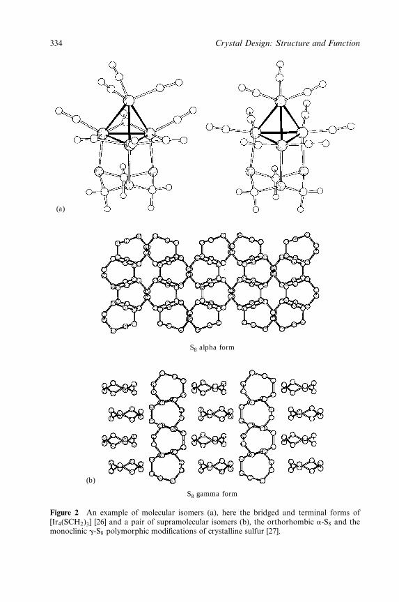
(a)
(b)
S8 alpha form
S8 gamma form
Figure 2 An example of molecular isomers (a), here the bridged and terminal forms of[Ir4(SCH2)3] [26] and a pair of supramolecular isomers (b), the orthorhombic a-S8 and themonoclinic g-S8 polymorphic modi®cations of crystalline sulfur [27].
334 Crystal Design: Structure and Function
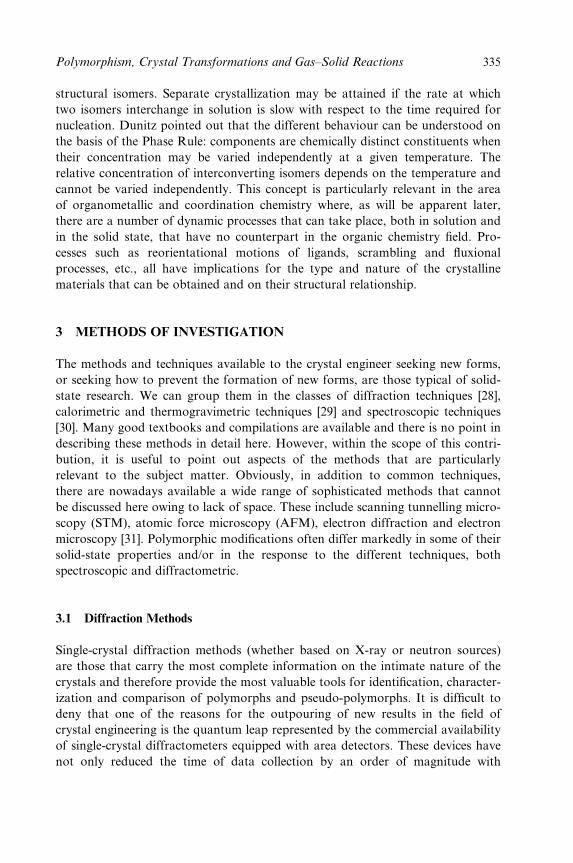
structural isomers. Separate crystallization may be attained if the rate at which
two isomers interchange in solution is slow with respect to the time required for
nucleation. Dunitz pointed out that the different behaviour can be understood on
the basis of the Phase Rule: components are chemically distinct constituents when
their concentration may be varied independently at a given temperature. The
relative concentration of interconverting isomers depends on the temperature and
cannot be varied independently. This concept is particularly relevant in the area
of organometallic and coordination chemistry where, as will be apparent later,
there are a number of dynamic processes that can take place, both in solution and
in the solid state, that have no counterpart in the organic chemistry ®eld. Pro-
cesses such as reorientational motions of ligands, scrambling and ¯uxional
processes, etc., all have implications for the type and nature of the crystalline
materials that can be obtained and on their structural relationship.
3 METHODS OF INVESTIGATION
The methods and techniques available to the crystal engineer seeking new forms,
or seeking how to prevent the formation of new forms, are those typical of solid-
state research. We can group them in the classes of diffraction techniques [28],
calorimetric and thermogravimetric techniques [29] and spectroscopic techniques
[30]. Many good textbooks and compilations are available and there is no point in
describing these methods in detail here. However, within the scope of this contri-
bution, it is useful to point out aspects of the methods that are particularly
relevant to the subject matter. Obviously, in addition to common techniques,
there are nowadays available a wide range of sophisticated methods that cannot
be discussed here owing to lack of space. These include scanning tunnelling micro-
scopy (STM), atomic force microscopy (AFM), electron diffraction and electron
microscopy [31]. Polymorphic modi®cations often differ markedly in some of their
solid-state properties and/or in the response to the different techniques, both
spectroscopic and diffractometric.
3.1 Diffraction Methods
Single-crystal diffraction methods (whether based on X-ray or neutron sources)
are those that carry the most complete information on the intimate nature of the
crystals and therefore provide the most valuable tools for identi®cation, character-
ization and comparison of polymorphs and pseudo-polymorphs. It is dif®cult to
deny that one of the reasons for the outpouring of new results in the ®eld of
crystal engineering is the quantum leap represented by the commercial availability
of single-crystal diffractometers equipped with area detectors. These devices have
not only reduced the time of data collection by an order of magnitude with
Polymorphism, Crystal Transformations and Gas±Solid Reactions 335
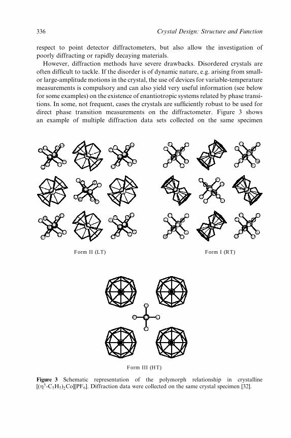
respect to point detector diffractometers, but also allow the investigation of
poorly diffracting or rapidly decaying materials.
However, diffraction methods have severe drawbacks. Disordered crystals are
often dif®cult to tackle. If the disorder is of dynamic nature, e.g. arising from small-
or large-amplitude motions in the crystal, the use of devices for variable-temperature
measurements is compulsory and can also yield very useful information (see below
for some examples) on the existence of enantiotropic systems related by phase transi-
tions. In some, not frequent, cases the crystals are suf®ciently robust to be used for
direct phase transition measurements on the diffractometer. Figure 3 shows
an example of multiple diffraction data sets collected on the same specimen
Form II (LT) Form I (RT)
Form III (HT)
Figure 3 Schematic representation of the polymorph relationship in crystalline[(Z5-C5H5)2Co][PF6]. Diffraction data were collected on the same crystal specimen [32].
336 Crystal Design: Structure and Function
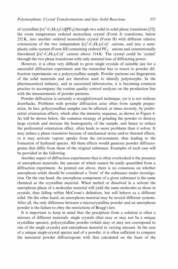
of crystalline [(Z5-C5H5)2Co][PF6] through two solid to solid phase transitions [32]:
the room temperature ordered monoclinic crystal (Form I) transforms, below
252K, into another ordered monoclinic crystal (Form II) with different relative
orientations of the two independent [(Z5-C5H5)2Co]� cations, and into a semi-
plastic cubic system (Form III) containing ordered PF ÿ6 anions and orientationally
disordered [(Z5-C5H5)2Co]� cations above 314K. The crystal could be `cycled'
through the two phase transitions with only minimal loss of diffracting power.
However, it is often very dif®cult to grow single crystals of suitable size for a
successful diffraction experiment and the researcher has to resort to powder dif-
fraction experiments on a polycrystalline sample. Powder patterns are ®ngerprints
of the solid materials and are therefore used to identify polymorphs. In the
pharmaceutical industry, and in associated laboratories, it is becoming common
practice to accompany the routine quality control analyses on the production line
with the measurements of powder patterns.
Powder diffraction is certainly a straightforward technique, yet it is not without
drawbacks. Problems with powder diffraction arise often from sample prepar-
ation. In fact, polycrystalline samples can be affected, at times severely, by prefer-
ential orientation effects, which alter the intensity sequence, as shown in Figure 4.
As will be shown below, the common strategy of grinding the powder to destroy
large crystals and increase the homogeneity of the sample, and hence to reduce
the preferential orientation effect, often leads to more problems than it solves. It
may induce a phase transition because of mechanical stress and/or thermal effects,
or it may activate vapour uptake from the environment, thus leading to the
formation of hydrated species. All these effects would generate powder diffracto-
grams that differ from those of the original substance. Examples of each case will
be provided in the following.
Another aspect of diffraction experiments that is often overlooked is the presence
of amorphous materials, the amount of which cannot be easily quanti®ed from a
diffraction experiment. As pointed out above, there is no consensus on whether
amorphous solids should be considered a `form' of the substance under investiga-
tion. On the one hand, the amorphous component of a given substance is the same
chemical as the crystalline material. When melted or dissolved in a solvent the
amorphous phase of a molecular material will yield the same molecules as those in
crystals, thus falling within McCrone's de®nition, but will behave as a different
solid. On the other hand, an amorphous material may be several different systems.
After all, the only difference between a microcrystalline powder and an amorphous
powder is the failure to obey the restrictions of Bragg's law.
It is important to keep in mind that the precipitate from a solution is often a
mixture of different materials: single crystals (that may or may not be a unique
crystalline species), polycrystalline powder (which may or may not correspond to
one of the single crystals) and amorphous material in varying amount. In the case
of a unique single-crystal species and of a powder, it is often suf®cient to compare
the measured powder diffractogram with that calculated on the basis of the
Polymorphism, Crystal Transformations and Gas±Solid Reactions 337
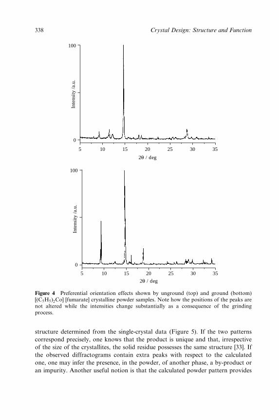
5
0
Inte
nsity
/a.u
.
100
0
Inte
nsity
/a.u
.
100
10 15 20
2θ / deg
25 30 35
5 10 15 20
2θ / deg
25 30 35
Figure 4 Preferential orientation effects shown by unground (top) and ground (bottom)[(C5H5)2Co] [fumarate] crystalline powder samples. Note how the positions of the peaks arenot altered while the intensities change substantially as a consequence of the grindingprocess.
structure determined from the single-crystal data (Figure 5). If the two patterns
correspond precisely, one knows that the product is unique and that, irrespective
of the size of the crystallites, the solid residue possesses the same structure [33]. If
the observed diffractograms contain extra peaks with respect to the calculated
one, one may infer the presence, in the powder, of another phase, a by-product or
an impurity. Another useful notion is that the calculated powder pattern provides
338 Crystal Design: Structure and Function
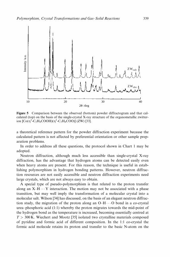
Inte
nsity
/a.u
.
10 202θ /deg
30 40
ZWcalc
ZWobs
Figure 5 Comparison between the observed (bottom) powder diffractogram and that cal-culated (top) on the basis of the single-crystal X-ray structure of the organometallic zwitter-ion [Co(Z5-C5H4COOH)(Z5-C5H4COO)] (ZW) [33].
a theoretical reference pattern for the powder diffraction experiment because the
calculated pattern is not affected by preferential orientation or other sample prep-
aration problems.
In order to address all these questions, the protocol shown in Chart 1 may be
adopted.
Neutron diffraction, although much less accessible than single-crystal X-ray
diffraction, has the advantage that hydrogen atoms can be detected easily even
when heavy atoms are present. For this reason, the technique is useful in estab-
lishing polymorphism in hydrogen bonding patterns. However, neutron diffrac-
tion resources are not easily accessible and neutron diffraction experiments need
large crystals, which are not always easy to obtain.
A special type of pseudo-polymorphism is that related to the proton transfer
along an X±H � � �Y interaction. The motion may not be associated with a phase
transition, but may well imply the transformation of a molecular crystal into a
molecular salt. Wilson [34] has discussed, on the basis of an elegant neutron diffrac-
tion study, the migration of the proton along an O±H � � �O bond in a co-crystal
urea±phosphoric acid (1:1) whereby the proton migrates towards the mid-point of
the hydrogen bond as the temperature is increased, becoming essentially centred at
T > 300K. Wiechert and Mootz [35] isolated two crystalline materials composed
of pyridine and formic acid of different composition. In the 1:1 co-crystal the
formic acid molecule retains its proton and transfer to the basic N-atom on the
Polymorphism, Crystal Transformations and Gas±Solid Reactions 339

CRYSTALIZATION BATCH FROM SOLUTIONExperimental step 1
Check single crystals with X-ray diffractionQuestion 1
Does the crystallization process yield only one type of single crystals?
YES
Experimental step 2Measure X-ray powder patternCollect data on single crystals
Compute powder patternCompare calculated and measured powder
patterns
Question 2Does the bulk possess the same solid state
structure as single crystals?NO
Go to Experimental step 3
NO
Concomitant polymorphs orpseudo-polymorphs
are present in the crystallization batch
Experimental step 3Check and vary the experimental
crystallization conditions
pyridine does not take place (hence molecules are linked by neutral O±H � � �Ninteractions). In the 1:4 co-crystal, in contrast, one formic acid molecule releases
its proton to the pyridine molecule establishing `charge-assisted' N±H(�) � � �O(ÿ)
interactions. In a sense (see also below) this latter case could be regarded as an
unusual case of a solvate crystal. Examples of this kind are rare, but serve to
stress how the phenomenon of polymorphism can be, at times, full of ambiguity.
3.2 Thermal Analysis and Differential Scanning Calorimetry
Differential scanning calorimetry (DSC) is the most widely used thermal technique
for the investigation of the relationship between polymorphic phases. The best
instruments for this purpose are those that provide thermal control on both the
heating and cooling cycles. The principle of DSC is very simple: any polymorph
undergoing a phase transition will absorb heat when heated through the transition.
Conversely, heat release will be observed on the cooling cycle. Heat absorptions/
releases will show up as peaks in the DSC plot, the area of the peak being propor-
tional to the DH of the transition. If a good baseline is determined, and if the
340 Crystal Design: Structure and Function
sample is pure and crystalline and its weight known with precision, a good estimate
of the DH involved in the process can be obtained. In the case of molecular crystals
these values are always in the range of few kilojoules per mole [36,37].
Conditions have to be chosen with care in order to obtain reliable and reprodu-
cible results. In fact, DSC measurements may be affected by several experimental
problems: baseline measurement, sample preparation, particle size, use of sealed
or open sample holders, and heating and cooling rates, which also affect
the thermal hysteresis between the endothermic and exothermic transitions. Base-
line preparation may be critical: an imperfect baseline may be indicative of some
imbalance between sample holder and reference but could also indicate
some change in the heat capacity of the sample, which, in turn, may indicate
decomposition or loss of solvent molecules. In the case of pseudo-polymorphs,
the solvent loss will generally appear as an endothermic process. The desolvation
can be very rapid, leading to a sharp peak, which, in turn, can be mistaken for a
phase transition. If the experiment is carried out in an open pan, it will not be
reversible and will not show the reverse endothermic peak on cooling. In a sealed
pan, on the other hand, cooling may bring vapour back in the crystal. Chemical
reactions can also take place during a DSC scan. A good example of an exother-
mic reaction is provided by crystalline bis-formylferrocene, [(Z5-C5H4CHO)2Fe]
[38], which on heating shows a phase transition at 311K, followed by an exother-
mic peak at 453K, corresponding to a polymerization reaction (see Figure 6).
This latter process is irreversible and the peak cancels out in the cooling cycle. If
the reaction taking place during a DSC scan is rapid and endothermic, however, it
may be confused with a solid-to-solid transition or with a melting process. The
corresponding endothermic peaks, however, will disappear in the cooling cycles.
This is why it is recommended to use DSC instruments that allow thermal control
in the cooling cycle. The rate of heating/cooling is also very important. If the
heating rate is fast an enantiotropic transition can be completely missed. It is not
uncommon for a polymorph to melt at the correct temperature when heated
rapidly while a transition to a higher melting form is observed when heated
slowly. In such cases further heating my lead to a recrystallization, which appears
as an exothermic peak, and then to a second melting. Decomposition under ther-
mal treatment is also critical. Since decomposition is a chemical reaction, it may
appear either as an endothermic or an exothermic process in the DSC plot
[36b].
As mentioned above, polymorphs may also be related by order±disorder transi-
tions, e.g. the onset of free rotation of a group of atoms, or local tumbling in
semi-plastic or plastic phases. This may be due to random orientation of the
molecules or ions, but is also diagnostic of the onset of a reorientational motion.
Roughly spherical molecules and ions are likely to show order±disorder phase
transitions to a plastic state. In the cases of co-crystals or of crystalline salts this
process may affect only one of the components, leading to semi-plastic crystals
(an example will be discussed below). Order±disorder phase transitions have often
Polymorphism, Crystal Transformations and Gas±Solid Reactions 341
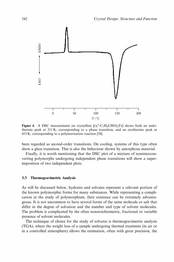
EX
OE
ND
O
0 50 100
T / 8C
150 200
Figure 6 A DSC measurement on crystalline [(Z5-C5H4CHO)2Fe] shows both an endo-thermic peak at 311 K, corresponding to a phase transition, and an exothermic peak at453 K, corresponding to a polymerization reaction [38].
been regarded as second-order transitions. On cooling, systems of this type often
show a glass transition. This is also the behaviour shown by amorphous material.
Finally, it is worth mentioning that the DSC plot of a mixture of nonintercon-
verting polymorphs undergoing independent phase transitions will show a super-
imposition of two independent plots.
3.3 Thermogravimetric Analysis
As will be discussed below, hydrates and solvates represent a relevant portion of
the known polymorphic forms for many substances. While representing a compli-
cation in the study of polymorphism, their existence can be extremely advanta-
geous. It is not uncommon to have several forms of the same molecule or salt that
differ in the degree of solvation and the number and type of solvent molecules.
The problem is complicated by the often nonstoichiometric, fractional or variable
presence of solvent molecules.
The technique of choice for the study of solvates is thermogravimetric analysis
(TGA), where the weight loss of a sample undergoing thermal treatment (in air or
in a controlled atmosphere) allows the estimation, often with great precision, the
342 Crystal Design: Structure and Function
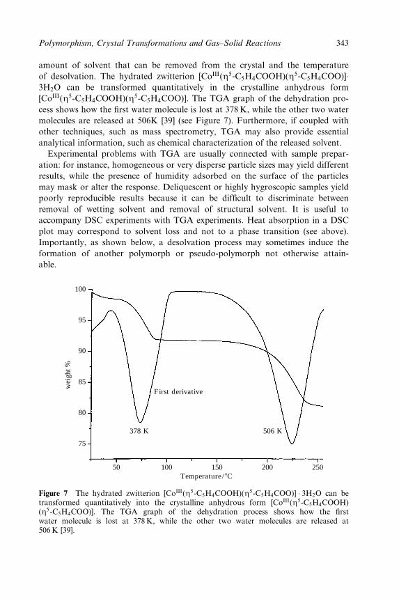
amount of solvent that can be removed from the crystal and the temperature
of desolvation. The hydrated zwitterion [CoIII(Z5-C5H4COOH)(Z5-C5H4COO)]�3H2O can be transformed quantitatively in the crystalline anhydrous form
[CoIII(Z5-C5H4COOH)(Z5-C5H4COO)]. The TGA graph of the dehydration pro-
cess shows how the ®rst water molecule is lost at 378K, while the other two water
molecules are released at 506K [39] (see Figure 7). Furthermore, if coupled with
other techniques, such as mass spectrometry, TGA may also provide essential
analytical information, such as chemical characterization of the released solvent.
Experimental problems with TGA are usually connected with sample prepar-
ation: for instance, homogeneous or very disperse particle sizes may yield different
results, while the presence of humidity adsorbed on the surface of the particles
may mask or alter the response. Deliquescent or highly hygroscopic samples yield
poorly reproducible results because it can be dif®cult to discriminate between
removal of wetting solvent and removal of structural solvent. It is useful to
accompany DSC experiments with TGA experiments. Heat absorption in a DSC
plot may correspond to solvent loss and not to a phase transition (see above).
Importantly, as shown below, a desolvation process may sometimes induce the
formation of another polymorph or pseudo-polymorph not otherwise attain-
able.
378 K 506 K
50 100 150Temperature/ 8C
200 250
100
95
90
85
wei
ght %
80
75
First derivative
Figure 7 The hydrated zwitterion [CoIII(Z5-C5H4COOH)(Z5-C5H4COO)] � 3H2O can betransformed quantitatively into the crystalline anhydrous form [CoIII(Z5-C5H4COOH)(Z5-C5H4COO)]. The TGA graph of the dehydration process shows how the ®rstwater molecule is lost at 378 K, while the other two water molecules are released at506 K [39].
Polymorphism, Crystal Transformations and Gas±Solid Reactions 343
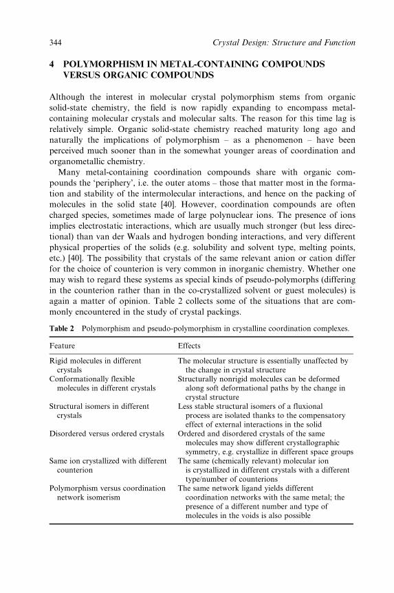
4 POLYMORPHISM IN METAL-CONTAINING COMPOUNDS
VERSUS ORGANIC COMPOUNDS
Although the interest in molecular crystal polymorphism stems from organic
solid-state chemistry, the ®eld is now rapidly expanding to encompass metal-
containing molecular crystals and molecular salts. The reason for this time lag is
relatively simple. Organic solid-state chemistry reached maturity long ago and
naturally the implications of polymorphism ± as a phenomenon ± have been
perceived much sooner than in the somewhat younger areas of coordination and
organometallic chemistry.
Many metal-containing coordination compounds share with organic com-
pounds the `periphery', i.e. the outer atoms ± those that matter most in the forma-
tion and stability of the intermolecular interactions, and hence on the packing of
molecules in the solid state [40]. However, coordination compounds are often
charged species, sometimes made of large polynuclear ions. The presence of ions
implies electrostatic interactions, which are usually much stronger (but less direc-
tional) than van der Waals and hydrogen bonding interactions, and very different
physical properties of the solids (e.g. solubility and solvent type, melting points,
etc.) [40]. The possibility that crystals of the same relevant anion or cation differ
for the choice of counterion is very common in inorganic chemistry. Whether one
may wish to regard these systems as special kinds of pseudo-polymorphs (differing
in the counterion rather than in the co-crystallized solvent or guest molecules) is
again a matter of opinion. Table 2 collects some of the situations that are com-
monly encountered in the study of crystal packings.
Table 2 Polymorphism and pseudo-polymorphism in crystalline coordination complexes.
Feature Effects
Rigid molecules in differentcrystals
The molecular structure is essentially unaffected bythe change in crystal structure
Conformationally flexiblemolecules in different crystals
Structurally nonrigid molecules can be deformedalong soft deformational paths by the change incrystal structure
Structural isomers in differentcrystals
Less stable structural isomers of a fluxionalprocess are isolated thanks to the compensatoryeffect of external interactions in the solid
Disordered versus ordered crystals Ordered and disordered crystals of the samemolecules may show different crystallographicsymmetry, e.g. crystallize in different space groups
Same ion crystallized with differentcounterion
The same (chemically relevant) molecular ionis crystallized in different crystals with a differenttype/number of counterions
Polymorphism versus coordinationnetwork isomerism
The same network ligand yields differentcoordination networks with the same metal; thepresence of a different number and type ofmolecules in the voids is also possible
344 Crystal Design: Structure and Function
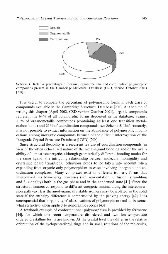
Organic
Organometallic
Coordination 11%
25%
64%
Scheme 3 Relative percentages of organic, organometallic and coordination polymorphiccompounds present in the Cambridge Structural Database (CSD, version October 2001)[20a].
It is useful to compare the percentage of polymorphic forms in each class of
compounds available in the Cambridge Structural Database [20a]. At the time of
writing this chapter (April 2002, CSD version October 2001), organic compounds
represent the 64 % of all polymorphic forms deposited in the database, against
11 % of organometallic compounds (containing at least one transition metal±
carbon bond) and 25 % of coordination compounds; see Scheme 3. Unfortunately,
it is not possible to extract information on the abundance of polymorphic modi®-
cations among inorganic compounds because of the dif®cult interrogation of the
Inorganic Crystal Structure Database (ICSD) [20b].
Since structural ¯exibility is a recurrent feature of coordination compounds, in
view of the often delocalized nature of the metal±ligand bonding and/or the avail-
ability of almost isoenergetic, although geometrically different, bonding modes for
the same ligand, the intriguing relationship between molecular nonrigidity and
crystalline phase transitional behaviour needs to be taken into account when
expanding from organic-only polymorphism to cases involving inorganic and co-
ordination complexes. Many complexes exist in different isomeric forms that
interconvert via low-energy processes (viz. reorientation, diffusion, scrambling
and ¯uxionality) both in the gas phase and in the condensed state [41]. Since the
structural isomers correspond to different energetic minima along the interconver-
sion pathway, less thermodynamically stable isomers may be isolated in the solid
state if the enthalpy difference is compensated by the packing energy [42]. It is
consequential that `organic-type' classi®cations of polymorphism tend to be some-
what restrictive when applied to nonorganic species [43].
A textbook example of conformational polymorphism is provided by ferrocene
[44], for which one room temperature disordered and two low-temperature
ordered crystalline forms are known. At the crystal level they differ in the relative
orientation of the cyclopentadienyl rings and in small rotations of the molecules,
Polymorphism, Crystal Transformations and Gas±Solid Reactions 345
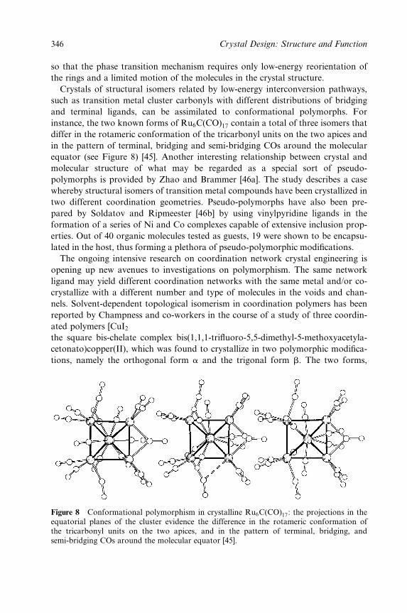
so that the phase transition mechanism requires only low-energy reorientation of
the rings and a limited motion of the molecules in the crystal structure.
Crystals of structural isomers related by low-energy interconversion pathways,
such as transition metal cluster carbonyls with different distributions of bridging
and terminal ligands, can be assimilated to conformational polymorphs. For
instance, the two known forms of Ru6C(CO)17 contain a total of three isomers that
differ in the rotameric conformation of the tricarbonyl units on the two apices and
in the pattern of terminal, bridging and semi-bridging COs around the molecular
equator (see Figure 8) [45]. Another interesting relationship between crystal and
molecular structure of what may be regarded as a special sort of pseudo-
polymorphs is provided by Zhao and Brammer [46a]. The study describes a case
whereby structural isomers of transition metal compounds have been crystallized in
two different coordination geometries. Pseudo-polymorphs have also been pre-
pared by Soldatov and Ripmeester [46b] by using vinylpyridine ligands in the
formation of a series of Ni and Co complexes capable of extensive inclusion prop-
erties. Out of 40 organic molecules tested as guests, 19 were shown to be encapsu-
lated in the host, thus forming a plethora of pseudo-polymorphic modi®cations.
The ongoing intensive research on coordination network crystal engineering is
opening up new avenues to investigations on polymorphism. The same network
ligand may yield different coordination networks with the same metal and/or co-
crystallize with a different number and type of molecules in the voids and chan-
nels. Solvent-dependent topological isomerism in coordination polymers has been
reported by Champness and co-workers in the course of a study of three coordin-
ated polymers [CuI2 bis(4-pyridyl)disul®de] [47a]. Another example is provided by
the square bis-chelate complex bis(1,1,1-tri¯uoro-5,5-dimethyl-5-methoxyacetyla-
cetonato)copper(II), which was found to crystallize in two polymorphic modi®ca-
tions, namely the orthogonal form a and the trigonal form b. The two forms,
Figure 8 Conformational polymorphism in crystalline Ru6C(CO)17: the projections in theequatorial planes of the cluster evidence the difference in the rotameric conformation ofthe tricarbonyl units on the two apices, and in the pattern of terminal, bridging, andsemi-bridging COs around the molecular equator [45].
346 Crystal Design: Structure and Function

which are characterized by the presence of extended networks, differ in the pat-
tern of the additional coordination interactions: whereas the a-form is a dense
solid, in the b-form the complex units assemble in a structure with open pores,
which can accommodate a variety of guest molecules; the `empty' porous b-form
has also been obtained, via a pseudo-polymorph, i.e. the porous b-form with
solvent in the cavities, and characterized [47b].
4.1 Noninterconverting Polymorphs
A textbook example of inorganic polymorphism is provided by the aragonite,
calcite and vaterite forms of calcium carbonate. These well studied systems [48]
differ, inter alia, in the coordination number of oxygen to calcium, as shown in
Figure 9.
Polymorphism is also shown by hydrogen-bonded systems, of which there are
several examples, e.g. oxalic acid that is known to form catemer-type motifs in the
a-form [49] and chains of hydrogen-bonded rings in the b-form (see Figure 10) [50].
Two polymorphic modi®cations are also known for the complex
[(Z2-fumaric acid)Fe(CO)4] (called forms I and II) [51]. In form I, the fumaric
acid ligands form ribbons of ligands joined by carboxylic rings. Interestingly, the
same arrangement is observed in crystalline fumaric acid [52], which also pos-
sesses two polymorphic forms both based on molecular chains interlinked via
hydrogen-bonded carboxylic rings. In form II the carboxylic rings form a cate-
mer-type pattern [52]. The complex HMn(CO)5, one of the ®rst carbonyl hydrides
to be structurally characterized by X-ray and neutron diffraction methods [53], is
known in two polymorphic forms, both monoclinic, called a-HMn(CO)5 and
b-HMn(CO)5. The complex [Cr0(Z6-C6H5COOH)2] forms a dimer via a pair of
typical hydrogen bonding rings involving the two ±COOH groups of the acid [54].
Aragonite Calcite Vaterite
Figure 9 Coordination of nine, six and eight Ocarbonate atoms around the calcium ion in thearagonite, calcite and vaterite forms of calcium carbonate [48].
Polymorphism, Crystal Transformations and Gas±Solid Reactions 347

alpha form
beta form
Figure 10 The oxalic acid forms catemer-type motifs in the a-form and chains of hydrogenbonded rings in the b-form [49].
Twin intermolecular hydrogen bonding of the type shown by [Cr0(Z6-C6H5
COOH)2] are not commonly observed with organic dicarboxylic acids, because
dimer formation requires a degree of structural ¯exibility that cannot be afforded by
molecules based on C±C s-bonds. In fact, dicarboxylic organic acids tend to form
chains joined by carboxylic rings in the solid state rather than self-assemble in
dimeric units. A strictly comparable situation can be observed in crystalline ferro-
cene dicarboxylic acid, [FeII(Z5-C5H4COOH)2] [55]. This acid is known in two poly-
morphic modi®cations (a monoclinic and a triclinic form), which contain exactly the
same type of dimeric unit, although in different arrangements in the solid state.
The space-®lling representations of the two forms of [FeII(Z5-C5H4COOH)2]
(Figure 1a) and of [Cr0(Z6-C6H5COOH)2] (Figure 11) show that the three crystals
are formed by layers of dimers arranged in contiguous rows. Two polymorphic
modi®cations of the oxidation product [CrI(Z6-C6H5COOH)2][PF6] have been crys-
tallized depending on the crystallization conditions [54]. Both forms contain chains
of cations held together by hydrogen bonds between the carboxyl groups. The
structure of the a-form can be ideally converted into that of the b-form by
348 Crystal Design: Structure and Function
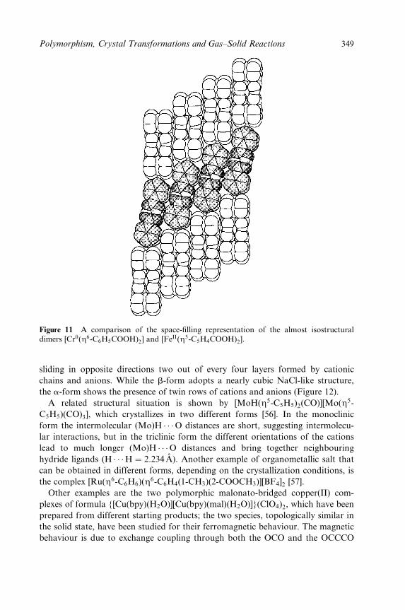
Figure 11 A comparison of the space-®lling representation of the almost isostructuraldimers [Cr0(Z6-C6H5COOH)2] and [FeII(Z5-C5H4COOH)2].
sliding in opposite directions two out of every four layers formed by cationic
chains and anions. While the b-form adopts a nearly cubic NaCl-like structure,
the a-form shows the presence of twin rows of cations and anions (Figure 12).
A related structural situation is shown by [MoH(Z5-C5H5)2(CO)][Mo(Z5-
C5H5)(CO)3], which crystallizes in two different forms [56]. In the monoclinic
form the intermolecular (Mo)H � � �O distances are short, suggesting intermolecu-
lar interactions, but in the triclinic form the different orientations of the cations
lead to much longer (Mo)H � � �O distances and bring together neighbouring
hydride ligands (H � � �H � 2:234 ÊA). Another example of organometallic salt that
can be obtained in different forms, depending on the crystallization conditions, is
the complex [Ru(Z6-C6H6)(Z6-C6H4(1-CH3)(2-COOCH3)][BF4]2 [57].
Other examples are the two polymorphic malonato-bridged copper(II) com-
plexes of formula {[Cu(bpy)(H2O)][Cu(bpy)(mal)(H2O)]}(ClO4)2, which have been
prepared from different starting products; the two species, topologically similar in
the solid state, have been studied for their ferromagnetic behaviour. The magnetic
behaviour is due to exchange coupling through both the OCO and the OCCCO
Polymorphism, Crystal Transformations and Gas±Solid Reactions 349
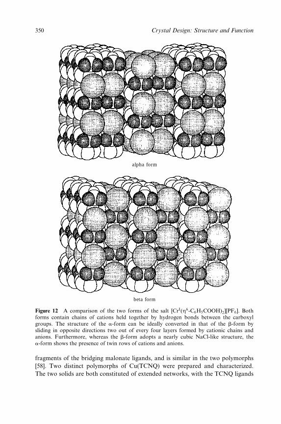
alpha form
beta form
Figure 12 A comparison of the two forms of the salt [CrI(Z6-C6H5COOH)2][PF6]. Bothforms contain chains of cations held together by hydrogen bonds between the carboxylgroups. The structure of the a-form can be ideally converted in that of the b-form bysliding in opposite directions two out of every four layers formed by cationic chains andanions. Furthermore, whereas the b-form adopts a nearly cubic NaCl-like structure, thea-form shows the presence of twin rows of cations and anions.
fragments of the bridging malonate ligands, and is similar in the two polymorphs
[58]. Two distinct polymorphs of Cu(TCNQ) were prepared and characterized.
The two solids are both constituted of extended networks, with the TCNQ ligands
350 Crystal Design: Structure and Function
connecting the copper atoms, but the relative orientation of the ligands is mark-
edly different in the two polymorphs. Phase I has been shown to be essentially
diamagnetic and a good semiconductor at room temperature, whereas phase II
displays Curie±Weiss behaviour down to very low temperature, and is a poor
semiconductor. The two phases have also been obtained as thin ®lms grown on
copper, and conversion from phase I to the more thermodynamically stable phase
II has been observed both in the crystals and in the thin ®lms [59].
4.2 Polymorphism Arising from Static/Dynamic Disorder and from
Order±Disorder Phase Transitions
As mentioned above, polymorphism may also arise for compounds formed by
isomers whose structures are related by low-energy interconversion pathways, e.g.
cluster carbonyls with different distributions of bridging and terminal ligands, or
substituted metallo-arenes and metallo-cyclopentadienyl complexes [60]. In such
cases, the structural isomers correspond to different energetic minima along the
interconversion pathway and the cohesion of the respective crystals may stabilize
the less thermodynamically stable isomers. Crystals of structural isomers may (or
may not) interconvert via a phase transition.
It must be mentioned that dynamic processes may introduce disorder in the
crystals [61] owing to the reorientational motions of whole molecules or groups of
atoms within the crystal structure. In such cases, a phase transition often occurs
when the temperature decreases and the dynamic process slows and ®nally stops.
Phase transitions are generally classi®ed as ®rst or second order. In terms of
Gibbs free energy, the transition is said to be ®rst order if the ®rst derivatives of
G(T,P) show an abrupt change at a given temperature, whereas second-order
phase transitions show a discontinuity in the second derivatives of G (i.e. volume
and entropy only show a change of slope at the transition point). The distinction
between the two phenomena is often ambiguous. In general, beside melting, nucle-
ation and growth of a new solid phase is ®rst order, whereas transformations in
which the molecules acquire orientational degrees of freedom, but with very
limited translational motion, are second order. In such cases, the phase transition
is associated with the onset of reorientational phenomena, in which the molecular
(or molecular fragment) orientation is distributed between more than one poten-
tial energy con®guration. As mentioned above, calorimetric measurements can be
exploited to gain complementary information on the transformations detected by
other methods, such as X-ray diffraction or NMR measurements. Both ®rst- and
second-order phenomena are accompanied by variations in the heat capacity
curves, which can be studied by DSC as discussed above.
Ordered and disordered crystals of the same molecules may have different point
symmetry arising from either static or dynamic disorder. It should be stressed that
the presence of disorder does not per se indicate the existence of different patterns
Polymorphism, Crystal Transformations and Gas±Solid Reactions 351
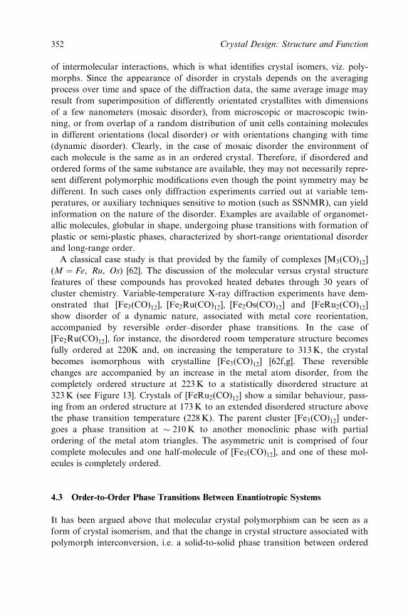
of intermolecular interactions, which is what identi®es crystal isomers, viz. poly-
morphs. Since the appearance of disorder in crystals depends on the averaging
process over time and space of the diffraction data, the same average image may
result from superimposition of differently orientated crystallites with dimensions
of a few nanometers (mosaic disorder), from microscopic or macroscopic twin-
ning, or from overlap of a random distribution of unit cells containing molecules
in different orientations (local disorder) or with orientations changing with time
(dynamic disorder). Clearly, in the case of mosaic disorder the environment of
each molecule is the same as in an ordered crystal. Therefore, if disordered and
ordered forms of the same substance are available, they may not necessarily repre-
sent different polymorphic modi®cations even though the point symmetry may be
different. In such cases only diffraction experiments carried out at variable tem-
peratures, or auxiliary techniques sensitive to motion (such as SSNMR), can yield
information on the nature of the disorder. Examples are available of organomet-
allic molecules, globular in shape, undergoing phase transitions with formation of
plastic or semi-plastic phases, characterized by short-range orientational disorder
and long-range order.
A classical case study is that provided by the family of complexes [M3(CO)12]
(M � Fe, Ru, Os) [62]. The discussion of the molecular versus crystal structure
features of these compounds has provoked heated debates through 30 years of
cluster chemistry. Variable-temperature X-ray diffraction experiments have dem-
onstrated that [Fe3(CO)12], [Fe2Ru(CO)12], [Fe2Os(CO)12] and [FeRu2(CO)12]
show disorder of a dynamic nature, associated with metal core reorientation,
accompanied by reversible order±disorder phase transitions. In the case of
[Fe2Ru(CO)12], for instance, the disordered room temperature structure becomes
fully ordered at 220K and, on increasing the temperature to 313K, the crystal
becomes isomorphous with crystalline [Fe3(CO)12] [62f,g]. These reversible
changes are accompanied by an increase in the metal atom disorder, from the
completely ordered structure at 223K to a statistically disordered structure at
323 K (see Figure 13]. Crystals of [FeRu2(CO)12] show a similar behaviour, pass-
ing from an ordered structure at 173K to an extended disordered structure above
the phase transition temperature (228 K). The parent cluster [Fe3(CO)12] under-
goes a phase transition at � 210K to another monoclinic phase with partial
ordering of the metal atom triangles. The asymmetric unit is comprised of four
complete molecules and one half-molecule of [Fe3(CO)12], and one of these mol-
ecules is completely ordered.
4.3 Order-to-Order Phase Transitions Between Enantiotropic Systems
It has been argued above that molecular crystal polymorphism can be seen as a
form of crystal isomerism, and that the change in crystal structure associated with
polymorph interconversion, i.e. a solid-to-solid phase transition between ordered
352 Crystal Design: Structure and Function
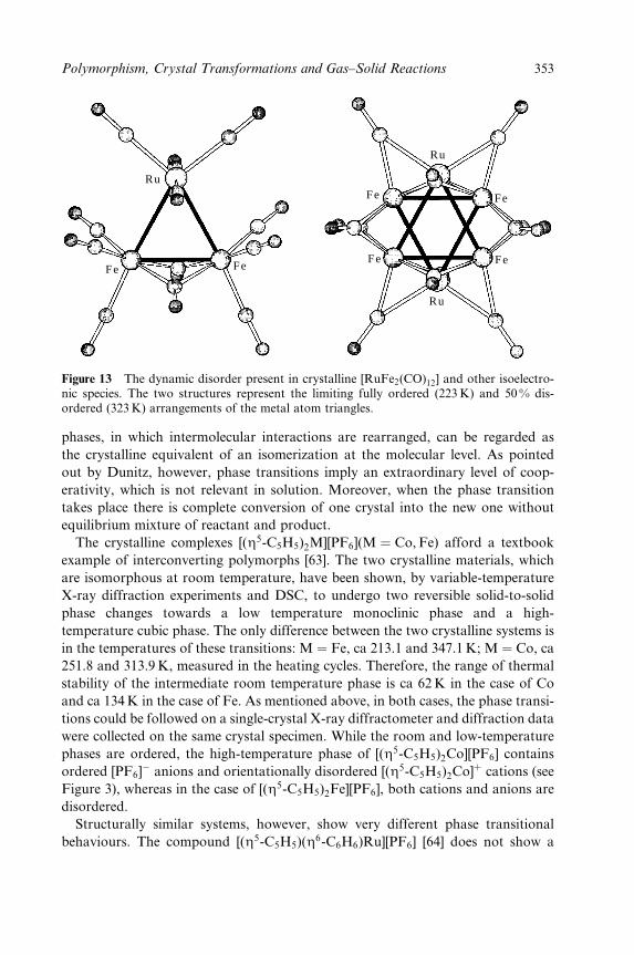
Ru
Ru
Ru
Fe
Fe
FeFe Fe
Fe
Figure 13 The dynamic disorder present in crystalline [RuFe2(CO)12] and other isoelectro-nic species. The two structures represent the limiting fully ordered (223 K) and 50% dis-ordered (323 K) arrangements of the metal atom triangles.
phases, in which intermolecular interactions are rearranged, can be regarded as
the crystalline equivalent of an isomerization at the molecular level. As pointed
out by Dunitz, however, phase transitions imply an extraordinary level of coop-
erativity, which is not relevant in solution. Moreover, when the phase transition
takes place there is complete conversion of one crystal into the new one without
equilibrium mixture of reactant and product.
The crystalline complexes [(Z5-C5H5)2M][PF6](M � Co, Fe) afford a textbook
example of interconverting polymorphs [63]. The two crystalline materials, which
are isomorphous at room temperature, have been shown, by variable-temperature
X-ray diffraction experiments and DSC, to undergo two reversible solid-to-solid
phase changes towards a low temperature monoclinic phase and a high-
temperature cubic phase. The only difference between the two crystalline systems is
in the temperatures of these transitions: M � Fe, ca 213.1 and 347.1 K; M � Co, ca
251.8 and 313.9 K, measured in the heating cycles. Therefore, the range of thermal
stability of the intermediate room temperature phase is ca 62 K in the case of Co
and ca 134K in the case of Fe. As mentioned above, in both cases, the phase transi-
tions could be followed on a single-crystal X-ray diffractometer and diffraction data
were collected on the same crystal specimen. While the room and low-temperature
phases are ordered, the high-temperature phase of [(Z5-C5H5)2Co][PF6] contains
ordered [PF6]ÿ anions and orientationally disordered [(Z5-C5H5)2Co]� cations (see
Figure 3), whereas in the case of [(Z5-C5H5)2Fe][PF6], both cations and anions are
disordered.
Structurally similar systems, however, show very different phase transitional
behaviours. The compound [(Z5-C5H5)(Z6-C6H6)Ru][PF6] [64] does not show a
Polymorphism, Crystal Transformations and Gas±Solid Reactions 353
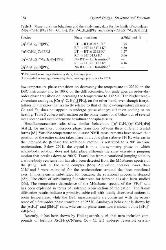
Table 3 Phase transition behaviour and thermodynamic data for the family of complexes[M(Z5-C5H5)][PF6](M � Co, Fe), [Cr(Z6-C6H6)2][PF6] and [Ru(Z5-C5H5)(Z6-C6H6)][PF6].
Species Phase transition DH(kJ molÿ1)
[(Z5-C5H5)2Fe][PF6] LT ! RT at 213.1 Ka 1.95RT ! HT at 347.1 Ka 4.50
[(Z5-C5H5)2Co][PF6] LT ! RT at 251.8 Ka 1.27RT ! HT 313.9 Ka 3.06
[(Z5-C5H5)(Z6-C6H6)Ru][PF6] No RT! LT transitionb ÐRT ! HT at 332.5 Ka 4.16
[(Z6-C6H6)2Cr][PF6] No RT! LT transitionb Ð
aDifferential scanning calorimetry data, heating cycle.bDifferential scanning calorimetry data, cooling cycle down to 223K.
low-temperature phase transition on decreasing the temperature to 223K on the
DSC instrument and to 100K on the diffractometer, but undergoes an order±dis-
order phase transition on increasing the temperature to 332.5 K. The bis(benzene)-
chromium analogue, [Cr(Z6-C6H6)2][PF6], on the other hand, even though it crys-
tallizes in a manner that is strictly related to that of the low-temperature phases of
Co and Fe, does not appear to undergo phase changes either on cooling or on
heating. Table 3 collects information on the phase transitional behaviour of several
metallocene and metallobenzene hexa¯uorophosphate salts.
Hexa¯uoroarseniate salts show similar behaviour. [(Z6-C6H6)(Z5-C5H5)Fe]
[AsF6], for instance, undergoes phase transition between three different crystal
forms [65]. Variable-temperature solid-state NMR measurements have shown that
rotation of the entire cation takes place in a cubic phase above 310K, whereas in
the intermediate b-phase the rotational motion is restricted to a 908 in-plane
reorientation. Below 270K the crystal is in a low-symmetry phase, in which
whole-body rotation does not take place although the rings execute a jumping
motion that persists down to 200K. Transition from a rotational jumping state to
a whole-body reorientation has also been detected from the MoÈssbauer spectra of
the [PF6]ÿ salt of the same complex [65b]. Activation energies lower than
20 kJ molÿ1 were estimated for the reorientations around the three rotational
axes. If mesitylene is substituted for benzene, the rotational process is stopped
[65b]. The effect of substituting ¯uorobenzene for benzene has also been studied
[65c]. The temperature dependence of the MoÈssbauer spectra of the [PF6]ÿ salt
has been explained in terms of isotropic reorientation of the cation. The X-ray
diffraction results indicate a primitive cubic cell with totally disordered cations at
room temperature, while the DSC measurements are consistent with the occur-
rence of a ®rst-order phase transition at 255K. Analogous behaviour is shown by
the [AsF6]ÿ and [SbF6]
ÿ salts, whereas no phase transition is shown by the [BF4]ÿ
salt [65c].
Recently, it has been shown by Hollingsworth et al. that urea inclusion com-
pounds of formula X(CH2)6CN/urea (X � Cl, Br) undergo reversible crystal-
354 Crystal Design: Structure and Function
to-crystal phase transitions associated with large translational motion of the guest
molecules [66].
As mentioned above, the metastable room temperature phase of crystalline bis-
formylferrocene, [Fe(Z5-C5H4CHO)2], on heating undergoes a ®rst transition at
ca 311K. On cooling, however, the reverse process leads to a new phase. Subse-
quent cycles of heating and cooling show that the new phase reversibly switches
between the room temperature and high-temperature phases, without reverting to
the initial phase. This behaviour suggests that the ®rst room temperature phase is
a kinetic product of the crystallization process: on heating, the sample undergoes
an order ! disorder phase transition to the plastic phase, which transforms
on cooling to a thermodynamically more stable form. Once this latter
phase is formed, the initial phase can no longer be obtained, unless the compound
is redissolved and recrystallized. The DH of transition (14:0 kJ molÿ1) is
comparable to the value (12:1 kJ molÿ1) found for the mono-formyl derivative
[Fe(Z5-C5H5)(Z5-C5H4CHO)] [67], which shows a mesophase between 316K and
the melting point (396 K). On further heating crystalline [Fe(Z5-C5H4CHO)2]
above the phase transition temperature, an exothermic peak is observed on the
DSC plot at 453 K (see Figure 6); this peak was taken as indicative of the occur-
rence of a polymerization reaction in the solid state.
5 INDUCING POLYMORPHS VIA NONSOLUTION METHODS
Thus far we have discussed polymorphism and interconversion between poly-
morphs. While these examples should suf®ce to show the many facets and prac-
tical implications of polymorphism, they have not provided insight into the
problem of making new crystal forms of the same substance. As mentioned in the
Introduction, any step forward in the understanding of how to make polymorphs
on purpose may represent a substantial advancement in a ®eld.
In synthetic laboratories, the most common method to obtain crystals is crys-
tallization from solution. In a way this is also the most dif®cult process to control.
The solvent evaporation rate can be affected by several factors such as ambient
humidity, temperature and ventilation, thermal excursion during the 24 h in the
case of `open air' room temperature crystallizations, and vibrations of the build-
ing (footsteps, traf®c, lifts, etc.) and of the refrigerators. There is no unique and
transferable recipe for the crystallization of a substance: Philip Ball concluded his
Nature Editorial in 1996 by saying, `the precipitation of good single crystals
remains a black magic' [68].
This section will focus on some examples of induced polymorphism. In particu-
lar, we will discuss how the formation of new crystalline phases may be achieved
by mechanical grinding and/or by thermal dehydration in TGA experiments and
how crystallization of these elusive phases may be obtained via seeding.
Polymorphism, Crystal Transformations and Gas±Solid Reactions 355
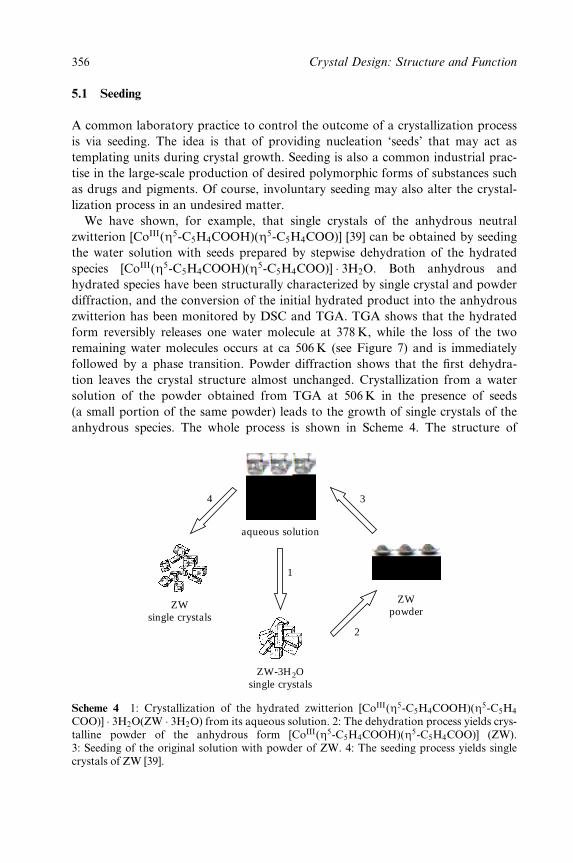
5.1 Seeding
A common laboratory practice to control the outcome of a crystallization process
is via seeding. The idea is that of providing nucleation `seeds' that may act as
templating units during crystal growth. Seeding is also a common industrial prac-
tise in the large-scale production of desired polymorphic forms of substances such
as drugs and pigments. Of course, involuntary seeding may also alter the crystal-
lization process in an undesired matter.
We have shown, for example, that single crystals of the anhydrous neutral
zwitterion [CoIII(Z5-C5H4COOH)(Z5-C5H4COO)] [39] can be obtained by seeding
the water solution with seeds prepared by stepwise dehydration of the hydrated
species [CoIII(Z5-C5H4COOH)(Z5-C5H4COO)] � 3H2O. Both anhydrous and
hydrated species have been structurally characterized by single crystal and powder
diffraction, and the conversion of the initial hydrated product into the anhydrous
zwitterion has been monitored by DSC and TGA. TGA shows that the hydrated
form reversibly releases one water molecule at 378 K, while the loss of the two
remaining water molecules occurs at ca 506K (see Figure 7) and is immediately
followed by a phase transition. Powder diffraction shows that the ®rst dehydra-
tion leaves the crystal structure almost unchanged. Crystallization from a water
solution of the powder obtained from TGA at 506K in the presence of seeds
(a small portion of the same powder) leads to the growth of single crystals of the
anhydrous species. The whole process is shown in Scheme 4. The structure of
aqueous solution
ZWpowder
ZWsingle crystals
ZW-3H2Osingle crystals
1
4
2
3
Scheme 4 1: Crystallization of the hydrated zwitterion [CoIII(Z5-C5H4COOH)(Z5-C5H4
COO)] � 3H2O(ZW � 3H2O) from its aqueous solution. 2: The dehydration process yields crys-talline powder of the anhydrous form [CoIII(Z5-C5H4COOH)(Z5-C5H4COO)] (ZW).3: Seeding of the original solution with powder of ZW. 4: The seeding process yields singlecrystals of ZW [39].
356 Crystal Design: Structure and Function
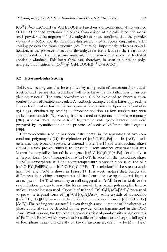
[CoIII(Z5-C5H4COOH)(Z5-C5H4COO)] is based on a one-dimensional network of
O±H � � �O bonded zwitterion molecules. Comparison of the calculated and meas-
ured powder diffractograms of the anhydrous phase con®rms that the powder
obtained at 506K and the single crystals precipitated at room temperature after
seeding possess the same structure (see Figure 5). Importantly, whereas crystal-
lization, in the presence of seeds of the anhydrous form, leads to the isolation of
single crystals of the anhydrous material, in the absence of seeds the hydrated
species is obtained. This latter form can, therefore, be seen as a pseudo-poly-
morphic modi®cation of [CoIII(Z5-C5H4COOH)(Z5-C5H4COO)].
5.2 Heteromolecular Seeding
Deliberate seeding can also be exploited by using seeds of isostructural or quasi-
isostructural species that crystallize well to achieve the crystallization of an un-
yielding material. The same procedure can also be exploited to freeze a given
conformation of ¯exible molecules. A textbook example of this latter approach is
the nucleation of orthorhombic ferrocene, which possesses eclipsed cyclopentadie-
nyl rings, obtained by seeding a ferrocene solution at low temperature with
ruthenocene crystals [69]. Seeding has been used in experiments of shape mimicry
[70a], whereas chiral co-crystals of tryptamine and hydrocinnamic acid were
prepared by crystallization in the presence of seeds of different chiral crystals
[70b].
Heteromolecular seeding has been instrumental in the separation of two con-
comitant polymorphs [71]. Precipitation of [(Z5-C5H5)2Fe]� as its [AsF6]ÿ salt
generates two types of crystals: a trigonal phase (Fe-T) and a monoclinic phase
(Fe-M), which proved dif®cult to separate. From another experiment, it was
known that crystallization of the congener [(Z5-C5H5)2Co]�[AsF6]ÿ leads only to
a trigonal form (Co-T) isomorphous with Fe-T. In addition, the monoclinic phase
Fe-M is isomorphous with the room temperature monoclinic phase of the pair
[(Z5-C5H5)2Fe][PF6] and [(Z5-C5H5)2Co][PF6]. The relationship between crystal-
line Fe-T and Fe-M is shown in Figure 14. It is worth noting that, besides the
differences in packing arrangements of the forms, the cyclopentadienyl ligands
are eclipsed in Fe-T, whereas they are all staggered in Fe-M. In order to drive the
crystallization process towards the formation of the separate polymorphs, hetero-
molecular seeding was used. Crystals of trigonal [(Z5-C5H5)2Co][AsF6] were used
to grow the trigonal form of [(Z5-C5H5)2Fe][AsF6], while crystals of monoclinic
[(Z5-C5H5)2Fe][PF6] were used to obtain the monoclinic form of [(Z5-C5H5)2Fe]
[AsF6]. The seeding was successful, even though a small amount of the alternative
phase could always be detected in the powder diffractograms and in the DSC
scans. What is more, the two seeding processes yielded good-quality single crystals
of Fe-T and Fe-M, which proved to be suf®ciently robust to undergo a full cycle
of four phase transitions directly on the diffractometer, (Fe-T ! Fe-M ! Fe-C
Polymorphism, Crystal Transformations and Gas±Solid Reactions 357
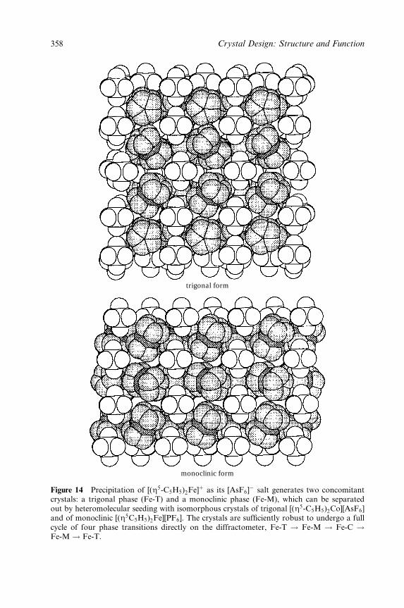
trigonal form
monoclinic form
Figure 14 Precipitation of [(Z5-C5H5)2Fe]� as its [AsF6]ÿ salt generates two concomitant
crystals: a trigonal phase (Fe-T) and a monoclinic phase (Fe-M), which can be separatedout by heteromolecular seeding with isomorphous crystals of trigonal [(Z5-C5H5)2Co][AsF6]and of monoclinic [(Z5C5H5)2Fe][PF6]. The crystals are suf®ciently robust to undergo a fullcycle of four phase transitions directly on the diffractometer, Fe-T ! Fe-M ! Fe-C !Fe-M ! Fe-T.
358 Crystal Design: Structure and Function
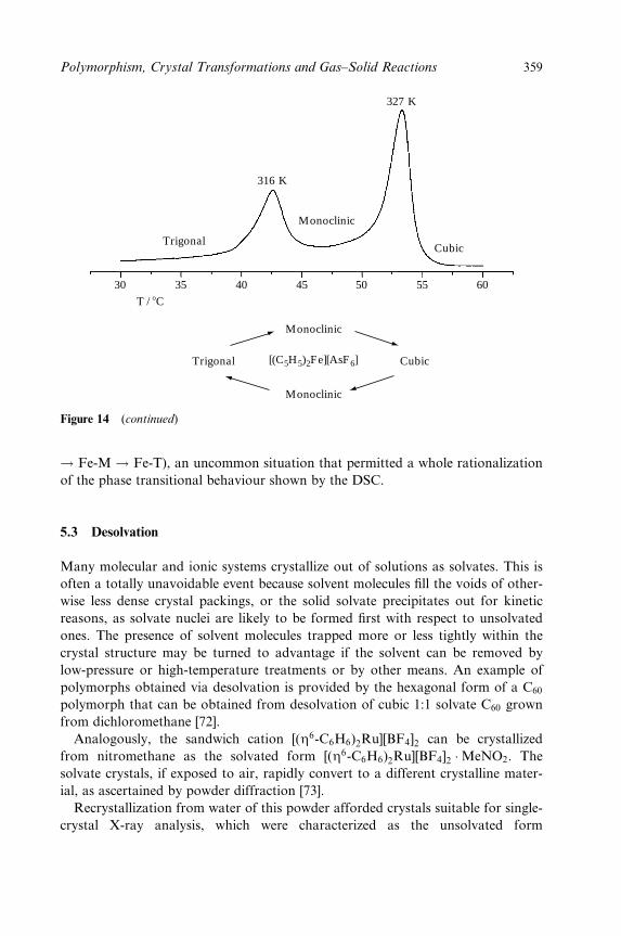
Trigonal
316 K
327 K
Monoclinic
Cubic
30 35 40 45 50 55 60
T / 8C
Monoclinic
Monoclinic
Trigonal Cubic[(C5H5)2Fe][AsF 6]
Figure 14 (continued)
! Fe-M ! Fe-T), an uncommon situation that permitted a whole rationalization
of the phase transitional behaviour shown by the DSC.
5.3 Desolvation
Many molecular and ionic systems crystallize out of solutions as solvates. This is
often a totally unavoidable event because solvent molecules ®ll the voids of other-
wise less dense crystal packings, or the solid solvate precipitates out for kinetic
reasons, as solvate nuclei are likely to be formed ®rst with respect to unsolvated
ones. The presence of solvent molecules trapped more or less tightly within the
crystal structure may be turned to advantage if the solvent can be removed by
low-pressure or high-temperature treatments or by other means. An example of
polymorphs obtained via desolvation is provided by the hexagonal form of a C60
polymorph that can be obtained from desolvation of cubic 1:1 solvate C60 grown
from dichloromethane [72].
Analogously, the sandwich cation [(Z6-C6H6)2Ru][BF4]2 can be crystallized
from nitromethane as the solvated form [(Z6-C6H6)2Ru][BF4]2 �MeNO2. The
solvate crystals, if exposed to air, rapidly convert to a different crystalline mater-
ial, as ascertained by powder diffraction [73].
Recrystallization from water of this powder afforded crystals suitable for single-
crystal X-ray analysis, which were characterized as the unsolvated form
Polymorphism, Crystal Transformations and Gas±Solid Reactions 359
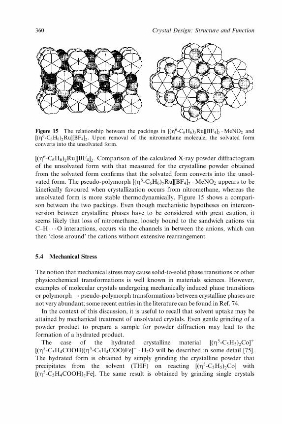
Figure 15 The relationship between the packings in [(Z6-C6H6)2Ru][BF4]2 �MeNO2 and[(Z6-C6H6)2Ru][BF4]2. Upon removal of the nitromethane molecule, the solvated formconverts into the unsolvated form.
[(Z6-C6H6)2Ru][BF4]2. Comparison of the calculated X-ray powder diffractogram
of the unsolvated form with that measured for the crystalline powder obtained
from the solvated form con®rms that the solvated form converts into the unsol-
vated form. The pseudo-polymorph [(Z6-C6H6)2Ru][BF4]2 �MeNO2 appears to be
kinetically favoured when crystallization occurs from nitromethane, whereas the
unsolvated form is more stable thermodynamically. Figure 15 shows a compari-
son between the two packings. Even though mechanistic hypotheses on intercon-
version between crystalline phases have to be considered with great caution, it
seems likely that loss of nitromethane, loosely bound to the sandwich cations via
C±H � � �O interactions, occurs via the channels in between the anions, which can
then `close around' the cations without extensive rearrangement.
5.4 Mechanical Stress
The notion that mechanical stress may cause solid-to-solid phase transitions or other
physicochemical transformations is well known in materials sciences. However,
examples of molecular crystals undergoing mechanically induced phase transitions
or polymorph! pseudo-polymorph transformations between crystalline phases are
not very abundant; some recent entries in the literature can be found in Ref. 74.
In the context of this discussion, it is useful to recall that solvent uptake may be
attained by mechanical treatment of unsolvated crystals. Even gentle grinding of a
powder product to prepare a sample for powder diffraction may lead to the
formation of a hydrated product.
The case of the hydrated crystalline material [(Z5-C5H5)2Co]�
[(Z5-C5H4COOH)(Z5-C5H4COO)Fe]ÿ �H2O will be described in some detail [75].
The hydrated form is obtained by simply grinding the crystalline powder that
precipitates from the solvent (THF) on reacting [(Z5-C5H5)2Co] with
[(Z5-C5H4COOH)2Fe]. The same result is obtained by grinding single crystals
360 Crystal Design: Structure and Function
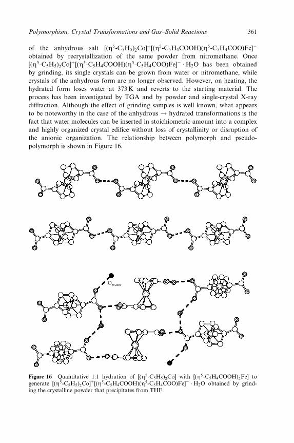
of the anhydrous salt [(Z5-C5H5)2Co]�[(Z5-C5H4COOH)(Z5-C5H4COO)Fe]ÿ
obtained by recrystallization of the same powder from nitromethane. Once
[(Z5-C5H5)2Co]�[(Z5-C5H4COOH)(Z5-C5H4COO)Fe]ÿ �H2O has been obtained
by grinding, its single crystals can be grown from water or nitromethane, while
crystals of the anhydrous form are no longer observed. However, on heating, the
hydrated form loses water at 373K and reverts to the starting material. The
process has been investigated by TGA and by powder and single-crystal X-ray
diffraction. Although the effect of grinding samples is well known, what appears
to be noteworthy in the case of the anhydrous ! hydrated transformations is the
fact that water molecules can be inserted in stoichiometric amount into a complex
and highly organized crystal edi®ce without loss of crystallinity or disruption of
the anionic organization. The relationship between polymorph and pseudo-
polymorph is shown in Figure 16.
Owater
Figure 16 Quantitative 1:1 hydration of [(Z5-C5H5)2Co] with [(Z5-C5H4COOH)2Fe] togenerate [(Z5-C5H5)2Co]�[(Z5-C5H4COOH)(Z5-C5H4COO)Fe]ÿ �H2O obtained by grind-ing the crystalline powder that precipitates from THF.
Polymorphism, Crystal Transformations and Gas±Solid Reactions 361
6 SOLID-STATE REACTIVITY ± GAS±SOLID REACTIONS AND
SOLVATION PROCESSES
The examples provided in the previous sections show that one of the means to
obtain new pseudo-polymorphs is via solvent uptake. Since the co-crystallizing
solvent may be present in the vapour phase (say water), one may regard the
process that leads from an unsolvated to a solvated species (and reverse) as a
supramolecular reaction whereby a given set of noncovalent bonds (those between
molecules in the nonsolvated form, for example) are broken and a new set of
noncovalent bonds (those between host and guest molecules) are formed as shown
at the beginning of this chapter in Scheme 2.
On this conceptual premise, uptake and release of solvent can be paralleled to a
solid±gas reaction, whereby the reactants are the molecules in the crystalline solid
and the molecules in the gas phase and the product is the solvated crystal. Clearly,
the same reasoning applies to the reverse process, i.e. generation of a new crystal-
line form by means of gas release. In gas±solid reactions, gases are reacted directly
with crystals or amorphous phases to give complete conversion and usually quan-
titative yields. What would then be the difference between a solvation reaction
and a reaction leading to new molecular/ionic species if not the energetic scale of
the processes and the fact that in solvation processes molecules retain their chem-
ical identity?
Heterogeneous gas±solid reactions are well known in chemistry. It has been
known for a long time that graphite reacts with metal vapours to form intercalation
compounds. The rusting of iron by atmospheric oxygen is a trivial example of a
heterogeneous solid±gas reaction, whereas the generation of a large quantity of
nitrogen in the reaction of solid NaN3 and KNO3 is exploited for the functioning
of air-bags in automobiles. It is also well known that thermal treatment of calcium
carbonate to remove CO2, as well as the reverse reaction during the drying process
of hydrated Ca(OH)2, is at the basis of the use of mortar in construction.
Furthermore, in the reactions between gases and solids the costs of removing
and reprocessing solvents are eliminated; this goes along with the great pressure
on developing solvent-free, i.e. environmentally more friendly reactions [76].
Beside gas±solid reactions, topochemical solid-state reactions of the type explored
by Schmidt [77] in the early days of crystal engineering are now experiencing a
wave of renewed interest [76,78]. A discussion of these aspects is beyond the scope
of this contribution. It is worth noting, however, that in spite of the wide range of
applications in both fundamental studies and in materials chemistry, heteroge-
neous reactions are still regarded as an oddity by chemists used to thinking of the
solution as the appropriate medium for reactivity.
In the following we shall focus on heterogeneous acid±base reactions, which
were among the ®rst processes to be studied. The Italian scientist Pellizzari stud-
ied the reaction of dry ammonia vapour with dried and pulverized phenols and
carboxylic acids [79]. This subject was taken up and extended by Paul, Curtin and
362 Crystal Design: Structure and Function
co-workers in a series of elegant studies [80±82]. One of the best known case
studies is the reaction of crystalline benzoic acid with ammonia. This process has
been studied on both powder and single crystals and also on a number of related
compounds. The reactions lead to quantitative formation of 1:1 ammonium salts.
They were able to demonstrate that certain crystal faces are attacked preferen-
tially by the ammonia vapour, and the resulting reaction front travels more rap-
idly through the crystals along directions corresponding to speci®c molecular
arrangements [81,82]. Crystalline p-chlorobenzoic anhydride reacts with gaseous
ammonia to give the corresponding amide and ammonium salt [83]; similar reac-
tion has been investigated in the case of optically active cyclopropanecarboxylic
acid crystals [84]. The possibility of reacting solid phenols with ammonia has been
known since the beginning of the last century. Even those phenols which are too
weakly acidic to react in solution form ammonium salts in heterogeneous pro-
cesses [31]. Interestingly, the reverse reactions, namely removal of gases from the
crystalline salts, has not been examined in detail.
A series of solid-state reactions have been explored by Kaupp et al. [85], in
which gaseous amines are reacted with aldehydes to give imines. Analogous reac-
tions with solid anhydrides, imides, lactones or carbonates and isothiocyanates
have been used to give, respectively, diamides or amidic carboxylic salts or imides,
diamides, carbamic acids and thioureas. In a number of cases investigated the
yields were found to be quantitative and no workup (except for washing in few
cases) is required in the 100% yield reactions. Upscaling to the kilogram scale was
also explored with good results. Ammonia and other gaseous amines, in particular
methylamine, have also been shown to aminolyse thermoplastic polycarbonates.
Such degradation processes have a high impact on the stability of data storage
compact disks [86].
Kaupp et al. have also exploited heterogeneous reactions with ClCN and BrCN
in the quantitative synthesis of cyanamides, cyanates, thiocyanates and derivatives
[87]. Various types of cyanamides can be prepared by the interaction of gaseous
cyanogen chloride or cyanogen bromide with crystalline primary or secondary
amines and with imide salts. All reactions were found to perform best in the
presence of gaseous trimethylamine, which binds the acid formed and makes
possible a quantitative use of the reacting base. The trimethylamine hydrohalide
that forms can be washed out with water, while the reaction product remains
solid. If the same reaction is carried in the liquid phase the yield is reduced to
45 %, showing that the solid±gas reaction is superior. It has been argued that the
possibility of obtaining quantitative reactions depends on the crystal packing,
which has to permit the occurrence of three distinct reaction stages: (1) phase
rebuilding with long-range molecular movements, (2) phase transformation into
the product lattice and (3) crystal disintegration to form fresh surfaces. In many
instances, these mechanisms could be veri®ed by AFM measurements and correl-
ated with the known crystal structures.
Polymorphism, Crystal Transformations and Gas±Solid Reactions 363
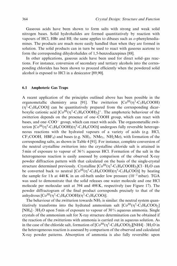
Gaseous acids have been shown to form salts with strong and weak solid
nitrogen bases. Solid hydrohalides are formed quantitatively by reaction with
vapours of HCl, HBr and HI; the same applies to dibases such as o-phenylenedia-
mines. The products are much more easily handled than when they are formed in
solution. The solid products can in turn be used to react with gaseous acetone to
form the corresponding dihydrohalides of 1,5-benzodiazepines [88].
In other applications, gaseous acids have been used for direct solid±gas reac-
tions. For instance, conversion of secondary and tertiary alcohols into the corres-
ponding chlorides has been shown to proceed ef®ciently when the powdered solid
alcohol is exposed to HCl in a desiccator [89,90].
6.1 Amphoteric Gas Traps
A recent application of the principles outlined above has been possible in the
organometallic chemistry area [91]. The zwitterion [CoIII(Z5-C5H4COOH)
(Z5-C5H4COO)] can be quantitatively prepared from the corresponding dicar-
boxylic cationic acid [CoIII(Z5-C5H4COOH)2]�. The amphoteric behaviour of the
zwitterion depends on the presence of one±COOH group, which can react with
bases, and one±COOÿ group, which can react with acids. The organometallic zwit-
terion [CoIII(Z5-C5H4COOH)(Z5-C5H4COO)] undergoes fully reversible heteroge-
neous reactions with the hydrated vapours of a variety of acids (e.g. HCl,
CF3COOH, HBF4) and bases (e.g. NH3, NMe3, NH2Me), with formation of the
corresponding salts, as shown in Table 4 [91]. For instance, complete conversion of
the neutral crystalline zwitterion into the crystalline chloride salt is attained in
5 min of exposure to vapour of 36 % aqueous HCl. Formation of the salt in the
heterogeneous reaction is easily assessed by comparison of the observed X-ray
powder diffraction pattern with that calculated on the basis of the single-crystal
structure determined previously. Crystalline [CoIII(Z5-C5H4COOH)2]Cl �H2O can
be converted back to neutral [CoIII(Z5-C5H4COOH)(Z5-C5H4COO)] by heating
the sample for 1 h at 440K in an oil-bath under low pressure (10ÿ2 mbar). TGA
was used to demonstrate that the solid releases one water molecule and one HCl
molecule per molecular unit at 394 and 498K, respectively (see Figure 17). The
powder diffractogram of the ®nal product corresponds precisely to that of the
anhydrous [CoIII(Z5-C5H4COOH)(Z5-C5H4COO)].
The behaviour of the zwitterion towards NH3 is similar: the neutral system quan-
titatively transforms into the hydrated ammonium salt [CoIII(Z5-C5H4COO)2]
[NH4] � 3H2O upon 5min of exposure to vapour of 30 % aqueous ammonia. Single
crystals of the ammonium salt for X-ray structure determination can be obtained if
the reaction of the zwitterions with ammonia is carried out in aqueous solution. As
in the case of the chloride salt, formation of [CoIII(Z5-C5H4COO)2][NH4] � 3H2O in
the heterogeneous reaction is assessed by comparison of the observed and calculated
X-ray powder patterns. Absorption of ammonia is also fully reversible: upon
364 Crystal Design: Structure and Function

Table 4 Reaction of solid [CoIII(Z5-C5H4COOH)(Z5-C5H4COO)] with hydrated acidand base vapours.
Acida Exposuretimeb
nCO(cmÿ1)c Basea Exposuretimeb
nCO(cmÿ1)c
HCl (37 %) 5min 1733(s) NH3 (30 %) 5min 1610(s)1707(s)
CF3COOH (99 %) 1 h 1723(s) NH2Me (30 %) 1 h 1610(s)1706(s)
HBF4 (54 %) 16 h 1736(s) NMe3 (30 %) 1 h 1612(s)1708(s)
aConcentration of the solutions in parentheses.bUptake time for a complete conversion of 10mg of [CoIII(Z5-C5H4COOH)(Z5-C5H4COO)];
all processes are fully reversible.cDiagnostic CO stretching frequencies (KBr) for reaction products. Neutral [CoIII(Z5-C5H4
COOH)(Z5-C5H4COO)] is characterized by two bands at 1717 and 1654 cmÿ1(Nujol).
CL−
OW
CoCo
CoOW
[NH4]+
+
CoO
O
OH
OH
CoO
O
O
OH
CoO
O
O
O
321
1(exp)
1(calc)
100
1200
Inte
nsity
/a.u
.
20 30
2θ /deg
40
2(exp)
2(calc)
100
1400
Inte
nsity
/a.u
.
20 30
2θ /deg
40
3(exp)
3(calc)
10
0
1200
Inte
nsity
/a.u
.
20 30
2θ /deg
40
-
+(HCI H2O)(vap)
-HCl-H2OC1−
H2O
+(NH3 3H2O)(vap)
-NH3
-3H2O [NH4]+
3H2O
Figure 17 Schematic representation of the uptake and release of hydrated vapours of HCland NH3 by crystalline [CoIII(Z5-C5H4COOH)(Z5-C5H4COO)]. Top: the different relativearrangements of the organometallic moieties in the solid state are shown. Bottom: compari-son of calculated and observed powder diffraction patterns.
thermal treatment (1 h at 373K, ambient pressure) the salts converts quantita-
tively into the neutral zwitterion. The material can be cycled through several
absorption and release processes of HCl or ammonia, as well as other gaseous
acids and bases (see Table 4) without decomposition or detectable formation of
Polymorphism, Crystal Transformations and Gas±Solid Reactions 365
amorphous material. Infrared spectroscopy can also be utilized to detect quickly
the formation of the organometallic cation or anion upon reaction with volatile
acids or bases (see Table 4). In summary, the organometallic zwitterionic system
[CoIII(Z5-C5H4COOH) (Z5-C5H4COO)] behaves as a fully reversible `amphoteric
trap' towards a variety of hydrated vapours of acids and bases.
7 CONCLUSION
The objective of this chapter has not been to provide a review on polymorphism,
but rather to attempt to bridge different aspects of solid-state chemistry and
molecular crystal engineering that have in common the existence of different
crystal forms of the same principal species. The question of whether a crystalline
material contains only molecules A in different arrangements (e.g. polymorphs),
or molecules A and molecules B, and whether this latter association ought to be
considered a co-crystal or a pseudo-polymorph, is somewhat semantic. It is un-
questionable, however, that crystals of different composition not only have differ-
ent crystal structures but also may possess different physical properties, such as
solubility, thermal behaviour, resistance to mechanical stress, gas-absorption/re-
lease capacity, colour, melting point, etc. These differences may be relevant, and
carry economic and practical implications, when considering, for instance, the
bioavailability of a drug or the thermal stability of a pigment.
In spite of the great interest in the phenomenon of polymorphism and of the
increased research activity beyond the boundaries of organic solid-state chemistry,
it is a fact that only a few molecular compounds possess several crystalline forms,
whereas for many other tens of thousands of molecular compounds only one
crystalline form is known. In other words, why are there so few molecular crystals
polymorphs? The often quoted association between number of known forms and
`the time and energy spent in searching for them' put forward by McCrone prob-
ably contains the answer to this question. It is probable that if thorough (com-
binatorial?) crystallization experiments were carried out on any given molecular
species or molecular salt, alternative crystalline forms would be found. It is prob-
able but not certain.
Reproducibility and predictability are paradigms in the exact sciences. This is
why, apart from all the utilitarian reasons associated with the marketing of solid-
state materials, we would like to learn how to make polymorphs, or, which is the
same, how effectively to prevent polymorph formation. One could argue that
polymorphism, with its high degree of serendipity, could be the nemesis of crystal
engineering because polymorphism is in logical contrast with a discipline that
aims to control and reproduce univocally a given crystal structure. Paul and
Curtin concluded their paper in Science in 1975 [80] by saying, `The recent ready
availability of crystal structure data for molecular crystals should lead to a more
rapid development of the principles governing the packing of such crystals and
366 Crystal Design: Structure and Function
their reactivity. The resulting control of such reactions should not only provide
the means of causing them when they are desired but also a means to prevent
them when they are to be avoided . . . '. Here is where we still stand almost 30
years later. Studies of crystal engineering are expected to shed light on the prin-
ciples governing packing hence on the way to make different crystals, and obtain
different properties, with the same molecules or ions.
In this chapter, we have described some common laboratory techniques and
practices for tackling problems of polymorphism and pseudo-polymorphism. In
the case of solids, routine analytical and spectroscopic laboratory tools are much
less useful than in solution chemistry. The utilization of powder diffraction is,
sometimes, the only way to ascertain whether the whole solid material has the
same structure as that characterized by single-crystal diffraction, i.e if they corres-
pond to the same crystal form. The notion that powder grinding, a common
method of sample preparation, may lead to solid-state transformations and to the
formation of new polymorphic modi®cations could be crucial for the success of
many crystal engineering processes and for many materials chemistry uses. While
scientists in the pharmaceutical industries are aware of this phenomenon and of
the possible consequences of tableting and other mechanical processing on solid
drugs, this awareness is not diffuse in the ®eld of crystal engineering, which still
has an essentially academic basis and originates from synthetic chemistry and
crystallography rather than from applied research in materials chemistry. Further-
more, since the crystallization product may not always be the most (thermo-
dynamically) stable system, it appears that any new solid material should be
subjected routinely to a DSC run in order to ascertain the possibility of phase
transitions. This is also a way to check if the crystalline product is a stable
thermodynamic form or only the one quickest to grow. One may envisage a
general approach to the relationship between polymorphs and pseudo-
polymorphs. If seeds of a polymorphic modi®cation can be obtained from
nonsolution methods (e.g. mechanical, thermodynamic, perhaps solid-state reac-
tions), these can be used in the seeding process, which may allow the growth of
less kinetically favoured (although often more thermodynamically stable) crystal
forms. Seeding may be valuable not only to obtain the desired crystalline form,
but also to prevent crystallization of undesired forms (e.g. ice-nine in Cat's Cradle;
see the quotation at the beginning of the chapter).
We have argued that the reaction of a solid with a vapour is conceptually
related to the supramolecular reaction of a crystalline material with a volatile
solvent to form a new crystalline solid. The two processes, solid±gas reaction and
solid±gas solvation, differ only in the energetic ranking of the interactions that are
broken or formed through the processes. In solvation±desolvation processes one is
dealing mainly with noncovalent van der Waals or hydrogen bonding interactions,
whereas in chemical reactions covalent bonds are broken or formed. The possibil-
ity of switching between interactions between charged species and molecules as a
consequence of proton transfers or redox processes should also be considered.
Polymorphism, Crystal Transformations and Gas±Solid Reactions 367
This awareness is useful to devise crystal engineering studies whereby gas uptake
is exploited not only to produce new crystalline forms of a given substance but
also as a means to produce new materials in crystalline form. Clearly the (concep-
tual) borderline between the two types of processes is very thin. One may then
purposefully plan to assemble molecules that are capable of absorbing molecules
from the gas phase and, possibly, to react with them. Reaction implies sensing
and could be exploited to detect molecules if there is a measurable response from
the solid state. If the reaction is quantitative and reversible, the same processes
(whether based on weak noncovalent bonding or on some type of covalent/ionic,
high-enthalpy, process) can be used to trap gases and deliver them where appro-
priate. Clearly, the control of solid-state reactions, that can be used to trap envir-
onmentally dangerous or poisonous molecules, is an attractive goal for solid-state
chemistry and crystal engineering.
The conclusion of this contribution is rather obvious. All in all, Natura non
facit saltus: solid-state reactivity and molecular materials engineering obey the
same basic rules as those governing polymorphism and solid-to-solid transform-
ations.
I closed my eyes.
There was a sound like that of the gentle closing of a portal as big as the sky, the
great door of heaven being closed softly.
It was a grand AH-WHOOM.
I opened my eyes ± and all the sea was ice-nine.
The moist green earth was a blue-white pearl.
K. Vonnegut, Cat's Cradle, Penguin Books, London, 1965, pp. 34, 37, 163.
ACKNOWLEDGMENTS
We gratefully acknowledge the support of MURST (projects Supramolecular
Devices 1999±2000 and Solid Supermolecules 2000±2001) and of the Universities
of Bologna (project Innovative Materials) and Sassari. We thank Professor Joel
Bernstein for continuing enthusiasm and for many useful discussions and Dr
Vincenzo Cannata (Zambon Group) for having brought many relevant problems
of polymorphism to our attention.
REFERENCES
1. D. Braga, F. Grepioni and A. G. Orpen (Eds), Crystal Engineering: from Molecules and
Crystals to Materials, Kluwer, Dordrecht, 1999.2. See, for example (a) D. W. Bruce and D. O'Hare (Eds), Inorganic Materials, Wiley,
Chichester, 1992; (b) S. R. Marder, Inorg. Mater., 115 (1992); (c) N. J. Long, Angew.
368 Crystal Design: Structure and Function
Chem., Int. Ed. Engl., 34, 21 (1995); (d) T. J. Marks and M.A. Ratner, Angew. Chem.,
Int. Ed. Engl., 34 (1995) 155; (e) D. R. Kanis, M. A. Ratner and T. J. Marks, Chem.
Rev., 94, 195 (1994); (f) O. Kahn, Molecular Magnetism, VCH, New York, 1993; (g) D.Gatteschi, Adv. Mater., 6, 635 (1994); (f) J. S. Miller and A. J. Epstein, Chem. Eng.
News, 73, 30 (1995); (g) Proceedings of the Dalton Discussion `Inorganic Crystal En-gineering', J. Chem. Soc., Dalton Trans., 3705 (2000), and references therein.
3. J.-M. Lehn (Ed.), Supramolecular Chemistry: Concepts and Perspectives, VCH, Wein-heim, 1995.
4. (a) D. Braga and F. Grepioni, Coord. Chem. Rev., 183, 19 (1999); (b) D. Braga, G.Coiazzi, L. Maini, M. Polito, L. Scaccianoce and F. Grepioni, Coord. Chem. Rev., 216,225 (2001); (c) G. R. Desiraju, Angew. Chem., Int. Ed. Engl., 34, 2311 (1995); (d) C. B.Aakeroy and K. R. Seddon, Chem. Soc. Rev., 397 (1993); (e) A. N. Khlobystov, A. J.Blake, N. R. Champness, D. A. Lemenovskii, A. G. Majouga, N. V. Zyk and M. SchroÈ-der, Coord. Chem. Rev., 222, 155 (2001); (f) M. Eddaoudi, D. B. Moler, H. L. Li, B. L.Chen, T. M. Reineke, M. O'Keeffe and O. M. Yaghi, Acc. Chem. Res., 34, 319 (2001).
5. D. Braga, and F. Grepioni Acc. Chem. Res., 33, 601 (2000).6. F. Takusagawa and T. F. Koetzle, Acta Crystallogr., Sect. B, 35, 2888 (1979).7. J. Bernstein, Polymorphism in Molecular Crystals, Oxford University Press, Oxford,
2002.8. J. K. Rowling, Harry Potter and the Philosopher's Stone, Bloomsbury Publishing,
London, 1997.9. J. Dunitz, and J. Bernstein, Acc. Chem. Res., 28, 193 (1995); see also J.-O. Henck, J.
Bernstein, A. Ellern and R. Boese, J. Am. Chem. Soc., 123, 1834 (2001).10. S. R. Chemburkar, J. Bauer, K. Deming, H. Spiwek, K. Patel, J. Morris, R. Henry, S.
Spanton, W. Dziki, W. Porter, J. Quick, P. Bauer, J. Donaubauer, B. A. Narayanan,M. Soldani, D. Riley and K. McFarland, Org. Process Res. Dev., 4, 413 (2000); J.Bauer, S. Spanton, R. Henry, J. Quick, W. Dziki, W. Porter and J. Morris, Pharm.
Res., 18, 859 (2001).11. (a) A. Gavezzotti, Acc. Chem. Res., 27, 309 (1994); (b) J. P. M. Lommerse, W. D. S.
Motherwell, H . L. Ammon, J. D. Dunitz, A. Gavezzotti, D. W. M. Hofmann, F. J. J.Leusen, W. T. M. Mooij, S. L. Price, B. Schweizer, M. U. Schmidt, B. P. van Eijck, P.Verwer and D. E. Williams, Acta Crystallogr., Sect. B, 56, 697 (2000); (c) T. Beyer,T. Lewis, and S. L. Price, CrystEngComm, 44, 1 (2001); (d) A. Gavezzotti, J. Am.
Chem. Soc., 122, 10724 (2000).12. (a) A. Burger, in Topics in Pharmaceutical Sciences, Eds D. D. Breimer and P. Speiser,
Elsevier, Amsterdam, 1983, p. 347; (b) T. L.Threlfall, Analyst, 120, 2435 (1995).13. S. R. Byrn, Solid State Chemistry of Drugs, Academic Press, New York, 1982, p. 79.14. W. C. McCrone, in Polymorphism in Physics and Chemistry of the Organic Solid State;
Eds D. Fox, M. M. Labes and A. Weissberger, Interscience, New York, 1965, vol. II,p. 726.
15. (a) J. Bernstein, in Organic Solid State Chemistry, Ed. G. R. Desiraju, Elsevier, Amster-dam, 1987, p. 471, and references therein; (b) J. Bernstein and A. T. Hagler, J. Am.
Chem. Soc., 100, 673 (1978); (c) J. Bernstein, in Structure and Properties of Molecular
Crystals, Ed. M. Pierrot, Elsevier, Amsterdam, 1990.16. (a) D. Braga and F. Grepioni, Chem. Soc. Rev., 4, 229 (2000); (b) see also D. Braga and
F. Grepioni, in Static and Dynamic Structures of Organometallic Molecules and Crys-
tals, Eds J. M. Brown and P. Hofmann, Topics in Organometallic Chemistry, vol. 4,Springer Berlin, 1999, p. 48; (c) D. Braga, G. Cojazzi, A. Abati, L. Maini, M. Polito, L.Scaccianoce and F. Grepioni, J. Chem. Soc., Dalton Trans., 3969 (2000).
17. (a) J. Bernstein, R. J. Davey and J.-O. Henck, Angew. Chem., Int. Ed. Engl., 38, 3440(1999); (b) see also N. Bladgen and R. J. Davey, Chem. Br., 35, 44 (1999).
Polymorphism, Crystal Transformations and Gas±Solid Reactions 369
18. (a) P. H. Poole, T. Grande, F. Sciortino, H. E. Stanley and C. A. Angell, Comput.
Mater. Sci., 4, 373 (1995); (b) B. C. Hancock and G. Zograf, J. Pharm. Sci., 86,1 (1997); (c) M. Yoshioka, B. C. Hancock and G. Zograf, J. Pharm. Sci., 83, 1700(1994); (d) M. Brinkmann, G. Gadret, M. Muccini, C. Taliani, N. Masciocchi and A.Sironi, J. Am. Chem. Soc., 122, 5147 (2002).
19. (a) C. H. GoÈrbitz and H.-P. Hersleth, Acta Crystalloger., Sect. B, 56, 526 (2000); (b) A.Nangia and G. R. Desiraju, Chem. Commun., 605 (1999); (c) B. Bechtloff, S. Nordhoffand J. Ulrich, Cryst. Res. Technol., 36, 1315 (2001).
20. (a) F. H. Allen and O. Kennard, Chem. Des. Autom. News, 8, 31 (1993); (b) InorganicCrystal Structure Database (ICSD), Fachinformationszentrum (FIZ), Karlsruhe, andGmelin Institut, Release 2000/2.
21. (a) V. A. Russell, C. C. Evans, W. Li and M. D. Ward, Science, 276, 575 (1997); (b) K. T.Holman, A. M. Pivovar, J. A. Swift, and M. D. Ward, Acc. Chem. Res., 34, 107 (2001);(c) O. M. Yaghi, G. Li and H. Li, Nature (London), 378, 703 (1995); (d) S.-I. Noro, S.Kitagawa, M. Kondo and K. Seki, Angew. Chem. Int. Ed. Engl., 39, 2082 (2000); (e) B. F.Abrahams, B. F. Hoskins, D. M. Michail and R. Robson, Nature (London), 369, 727(1994); (f) C. N. R. Rao, N. Srinivasan, A. Choudhury, S. Neeraj and A. A. Ayi, Acc.
Chem. Res., 34, 80 (2001); (g) M. Fujita, Acc. Chem. Res., 32, 53 (1999).22. (a) M. Albrecht, M. Lutz, A. L. Speck and G. van Koten, Nature (London), 406, 970
(2000); (b) M. Albrecht, R. A. Gossage, M. Lutz, A. L. Speck and G. van Koten,Chemistry, 6, 1431 (2000); (c) M. Albrecht, A. M. M. Schreurs, M. Lutz, A. L. Speckand G. van Koten, J. Chem. Soc., Dalton Trans., 3797 (2000).
23. (a) I. C. Paul and D. Y. Curtin, Acc. Chem. Res., 6, 217 (1973); (b) R. S. Miller, D. Y.Curtin and I. C. Paul, J. Am. Chem. Soc., 96, 6340 (1974).
24. D. Braga Chem. Rev., 92, 369 (1992).25. (a) G. R. Desiraju (Ed.), The Crystal as a Supramolecular Entity. Perspectives in Supra-
molecular Chemistry, vol. 2, Wiley, Chichester, 1996, p. 107; (b) J. D. Dunitz, Acta
Crystallogr., Sect. B, 51, 619 (1995).26. D. Braga and F. Grepioni, J. Chem. Soc., Dalton Trans., 1223 (1993).27. (a) P. Coppens, Y. W. Yang, R. H. Blessing and W. F. Cooper, J. Am. Chem. Soc., 99,
760 (1977); (b) A. C. Gallacher and A. A. Pinkerton, Acta Crystallogr., Sect.C, 49, 125(1993).
28. (a) J. D. Dunitz, X-ray Analysis and the Structure of Organic Molecules, VHCA, Basel,1995; (b) D. L. Bish and J. E. Post (Eds), `Modern Powder Diffraction', Rev. Miner.,20, 19 (1989); (c) K. D. M. Harris, and M. Tremayne, Chem. Mater., 8, 2554 (1996); (d)K. D. M. Harris, M. Tremayne and B. M. Kariuki, Angew. Chem., Int. Ed. Engl., 40,1626 (2001).
29. (a) A. K. Cheetham (Ed.), Solid State Chemistry Techniques, Oxford University Press,Oxford, 1987; (b) F. H. Herbstein, J. Mol. Struct., 374, 111 (1996); (c) S. Materazzi,Appl. Spectrose. Rev. 33, 189 (1998).
30. (a) D. E. Bugay, Adv. Drug Deliv. Rev., 48, 43, (2001); (b) C. A. Fyfe, Solid State NMR
for Chemists, ACFC Press, Ontario, 1983.31. G. Kaupp, in Comprehensive Supramolecular Chemistry, Ed. J. E. D. Davies, Elsevier,
Oxford, vol. 8, 1996, p. 381.32. D. Braga, L. Scaccianoce, F. Grepioni and S. M. Draper, Organometallics, 15, 4675
(1996).33. D. Braga, L. Maini, M. Polito, M. Rossini and F. Grepioni, Chem. Eur. J., 6, 4227
(2000).34. C. C. Wilson, Acta Crystallogr., Sect. B, 57, 435 (2001).35. D. Wiechert and D. Mootz, Angew. Chem., Int. Ed. Engl., 38, 1974 (1999).
370 Crystal Design: Structure and Function

36. (a) S. L. Simon, Thermochim. Acta, 374, 55 (2001); (b) D. Dollimore, and P. Phang,Anal. Chem., 72, 27R (2000).
37. S. D. Clas, C. R. Dalton and B. C. Hancock, Pharm. Sci. Technol. Today, 2, 311(1999).
38. D. Braga, F. Paganelli, E. Tagliavini, S. Casolari, G. Cojazzi and F. Grepioni, Organo-
metallics, 18, 4191 (1999).39. D. Braga, G. Cojazzi, L. Maini, M. Polito and F. Grepioni, Chem. Commun., 1949
(1999).40. D. Braga and F. Grepioni, Acc. Chem. Res., 27, 51 (1994).41. See, for instance, L. J. Farrugia, J. Chem. Soc., Dalton Trans., 1783 (1997), and refer-
ences therein.42. M. J. Calhorda, D. Braga and F. Grepioni, in Metal Clusters in Chemistry, Eds P.
Braunstein, L. Oro and P. R. Raithby, Wiley-VCH, Weinheim, 1999.43. D. Braga and F. Grepioni, in Organometallic Bonding and Reactivity ± Fundamental
Studies, Eds J. M. Brown and P. Hofmann, Springer, Berlin, 1999, p. 47.44. (a) P. Seiler and J. D. Dunitz, Acta Crystallogr., Sect. B, 35, 2020 (1979); (b) F.
Takusagawa, and T. F. Koetzle, Acta Crystallogr., Sect. B, 35, 1074 (1979); (c) P. Seilerand J. D. Dunitz, Acta Crystallogr., Sect. B, 35, 1068 (1979); (d) D. Braga, and F.Grepioni, Organometallics, 11, 711 (1992); (e) J. D. Dunitz, Acta Crystallogr., Sect B,51, 619 (1995); (f) J. D. Dunitz, in Organic Chemistry: Its Language and its State of the
Art, Ed. M. V. KisakuÈrek, Verlag Chemie, Basel, 1993, p. 9.45. D. Braga, F. Grepioni, B. F. G. Johnson, P. Dyson, P. Frediani, M. Bianchi, F.
Piacenti and J. Lewis, J. Chem. Soc., Dalton Trans., 2565 (1992).46. (a) D. Zhao and L. Brammer, Inorg. Chem., 33, 5897 (1994); (b) D. V. Soldatov and J.
A. Ripmeester, Chem. Eur. J., 7, 2979 (2001).47. (a) A. J. Blake, N. R. Brooks, N. R. Champness, M. Crew, A. Deveson, D. Fenske, D.
H. Gregory, L. R. Hanton, P. Hubberstey and M. Schroder, Chem. Commun., 16, 1432,(2001); (b) D. V. Soldatov, J. A. Ripmeester, S. I. Svergina, I. E. Sokolov, A. S.Zanina, S. A. Gromilov and Y. A. Dyadin, J. Am. Chem. Soc., 121, 4179 (1999).
48. (a) H. Effenberger, K. Mereiter and J. Zemann, Z. Kristallogr., 156, 233 (1981); (b) D.Jarosch and G. Heger, Tschermaks Mineral. Petrogr. Mitt., 35, 127 (1986); (c) H. J.Meyer, Z. Kristallogr., 128, 183 (1969).
49. V. R. Thalladi, M. Nusse and R. Boese, J. Am. Chem. Soc., 122, 9227 (2000).50. J. L. Derissen and P. H. Smit, Acta Crystallogr., Sect. B, 30, 2240 (1974).51. (a) C. Pedone and A. Sirigu, Inorg.Chem., 7, 2614 (1968); (b) Y. Hsiou,Y. Wang and
L.-K. Liu Acta Crystallogr., Sect. C, 45, 721 (1989).52. (a) C. J. Brown, Acta Crystallogr., 21, 1 (1966); (b) A. L. Bednowitz, and B. Post, Acta
Crystallogr., 21, 566 (1966).53. S. J. La Placa, W. C. Hamilton, J. A. Ibers and A. Davison, Inorg. Chem., 8, 1928 (1969).54. D. Braga, L. Maini, F. Grepioni, C. Elschenbroich, F. Paganelli and O. Schiemann,
Organometallics, 20, 1875 (2001).55. F. Takusagawa and T. F. Koetzle, Acta Crystallogr., Sect. B, 35, 2888 (1979).56. (a) A. S. Antsyshkina, L. M. Dikareva, M. A. Porai- Koshits, V. N. Ostrikova, Yu. V.
Skripkin, O. G. Volkov, A. A. Pasynskii and V. T. Kalinnikov, Koord. Khim., 11, 82(1985); (b) J. A. Marsella, J. C. Huffman, K. G. Caulton, B. Longato and J. R.Norton, J. Am. Chem. Soc., 104, 6360 (1982).
57. D. Braga, A. Abati, L. Scaccianoce, B. F. G. Johnson and F. Grepioni Solid State Sci.,3, 783 (2001).
58. C. R-PeÂrez, M. HernaÂndez-Molina, P. Lorenzo-Luis, F. Lloret, J. Cano and M. Julve,Inorg. Chem., 39, 3845 (2000).
Polymorphism, Crystal Transformations and Gas±Solid Reactions 371

59. R. A. Heintz, H. Zhao, X. Ouyang, G. Grandinetti, J. Cowen and K. Dunbar, Inorg.
Chem., 38, 144 (1999).60. D. Braga, P. J. Dyson, F. Grepioni, and B. F. G. Johnson Chem. Rev., 94, 1585 (1994).61. N. G. Parsonage and L. A. K. Staveley, Disorder in Crystals, Clarendon Press, Oxford,
1978.62. (a) D. Braga, F. Grepioni, B. F. G. Johnson and J. Farrugia, J. Chem. Soc., Dalton
Trans., 2911 (1994); (b) H. Dorn, B. E. Hanson, and E. Motell, Inorg. Chim. Acta, 54,L71 (1981); (c) B. E. Hanson, E. C. Lisic, J. T. Petty and G. A. Iannacone, Inorg.
Chem., 25, 4062 (1986); (d) B. E. Mann, J. Chem. Soc., Dalton Trans., 1457 (1997); (e)B. F. G. Johnson, J. Chem. Soc., Dalton Trans., 1473 (1997); (f) D. Braga, J. Farrugia,F. Grepioni and A. Senior, J. Chem. Soc., Chem. Commun., 1219 (1995); (g) D. Braga,J. Farrugia, A. L. Gillon, F. Grepioni and E. Tedesco, Organometallics, 15, 4684(1996).
63. (a) D. Braga, L. Scaccianoce, F. Grepioni and S. M. Draper, Organometallics, 15, 4675(1996); (b) F. Grepioni, G. Cojazzi, S. M. Draper, N. Scully and D. Braga, Organome-
tallics, 17, 296 (1998).64. F. Grepioni, G. Cojazzi, D. Braga, E. Marseglia, L. Scaccianoce and B. F. G. Johnson
J. Chem. Soc., Dalton Trans., 553 (1999).65. (a) B. W. Fitzsimmons and A. R. Hume, J. Chem. Soc., Dalton Trans., 180 (1980); (b)
B. W. Fitzsimmons and W. G. Marshall, J. Chem. Soc., Dalton Trans., 73 (1992); (c) B.W. Fitzsimmons and I. Sayer, J. Chem. Soc., Dalton Trans., 2907 (1991).
66. M. D. Hollinsgworth, M. L. Peterson, K. L. Pate, B. D. Dinkelmeyer and M. E.Brown, J. Am. Chem. Soc., 124, 2094 (2002).
67. M. F. Daniel, A. J. Leadbetter, R. E. Meads and W. G. Parker, J. Chem. Soc., Faraday
Trans., 74, 456 (1978).68. P. Ball, Nature (London), 381, 20 (1996).69. P. Seiler and J. D. Dunitz, Acta Crystallogr., Sect. B, 38, 1741 (1982).70. (a) R. J. Davey, N. Blagden, G. D. Potts and R. Docherty, J. Am. Chem. Soc., 119,
1767 (1997); (b) H. Koshima and M. Miyauchi, Cryst. Growth Des., 1, 355 (2001).71. D. Braga, G. Cojazzi, D. Paolucci and F. Grepioni, CrystEngComm, 38, 1 (2001).72. R. CeÂolin, J. Ll. Tamarit, M. Barrio, D. O. LoÂpez, S. Toscani, H. Allouchi, V. Agafo-
nov and H. Szwarc, Chem. Mater., 13, 1349 (2001).73. D. Braga, G. Cojazzi, A. Abati, L. Maini, M. Polito, L. Scaccianoce and F. Grepioni,
J. Chem. Soc., Dalton Trans., 3969 (2000).74. (a) M. R. Caira, Top. Curr. Chem., 198, 163 (1998); (b) M. R. Caira, L. R. Nassimbeni
and M. Timme, J. Pharm. Sci., 4, 884 (1995); (c) W. H. Ojala and M. C. Etter, J. Am.
Chem. Soc., 114, 10288 (1992); (d) M. M. Devilliers, J. G. Vanderwatt and A. P. Lotter,Drug Dev. Ind. Pharm., 17, 1295 (1991); (e) R. J. Webb, T. Y. Dong, C. G. Pierpont,S. R. Boone, R. K. Chadha and D. N. Hendrickson, J. Am. Chem. Soc., 113, 4806(1991).
75. D. Braga, L. Maini and F. Grepioni, Chem. Commun., 937 (1999).76. K. Tanaka and F. Toda, Chem. Rev., 100, 1025 (2000), and references therein.77. G. M. J. Schmidt, Pure Appl. Chem., 27, 647 (1971).78. L. R. MacGillivray, CrystEngComm, 7, 1 (2000), and references therein.79. G. Pellizzari, Gazz. Chim. Ital., 14, 362 (1884).80. I. C. Paul and D. Y. Curtin, Science, 187, 19 (1975).81. (a) R. S. Miller, D. Y. Curtin and I. C. Paul, J. Am. Chem. Soc., 93, 2784 (1971); (b)
R. S. Miller, D. Y. Curtin and I. C. Paul, J. Am. Chem. Soc., 94, 5117 (1972); (c) R. S.Miller, D. Y. Curtin and I. C. Paul, J. Am. Chem. Soc., 96, 6329 (1974); (d) C. C.Chiang, C.-T. Lin, A. H.-J. Wang, D. Y. Curtin and I. C. Paul, J. Am. Chem. Soc., 99,6303 (1977).
372 Crystal Design: Structure and Function
82. R. S. Miller, I. C. Paul and D. Y. Curtin, J. Am. Chem. Soc., 96, 6334 (1974).83. C. T. Lin, I. C. Paul and D. Y. Curtin, J. Am. Chem. Soc., 96, 3699 (1974).84. R. S. Miller, D. Y. Curtin and I. C Paul, J. Am. Chem. Soc., 96, 6340 (1974).85. G. Kaupp, J. Schmeyers and J. Boy, Tetrahedron, 56, 6899 (2000).86. (a) G. Kaupp and A. Kuse, Mol. Cryst. Liq. Cryst., 313, 36 (1998); (b) G. Kaupp, Mol.
Cryst. Liq. Cryst., 242, 153, (1994); (c) G. Kaupp, J. Schmeyers, M. Haak, T. Mar-quardt and A. Herrmann, Mol. Cryst. Liq. Cryst., 276, 315 (1996).
87. G. Kaupp, J. Schmeyers and J. Boy, Chem. Eur. J., 4, 2467 (1998).88. G. Kaupp, U. Pogodda, and J. Schmeyers, Chem. Ber., 127, 2249 (1994).89. F. Toda, H. Takumi, and M. Akehi, J. Chem. Soc., Chem. Commun., 1270 (1990).90. (a) F. Toda and K. Okuda, J. Chem. Soc., Chem. Commun., 1212 (1991): (b) K.
Tanaka, D. Fujimoto, T. Oeser, H. Irngartinger and F. Toda, Chem. Commun., 413(2000).
91. (a) D. Braga, G. Cojazzi, D. Emiliani, L. Maini and F. Grepioni, Chem. Commun.,2272 (2001); (b) D. Braga, G. Cojazzi, D. Emiliani, L. Maini and F. Grepioni, Organo-
metallics, 21, 1315 (2002).
Polymorphism, Crystal Transformations and Gas±Solid Reactions 373
Chapter 9
Solid±Gas Interactions BetweenSmall Gaseous Molecules andTransition Metals in theSolid State. Toward SensorApplications
MICHEL D. MEIJER, ROBERTUS J. M. KLEIN GEBBINK,
AND GERARD VAN KOTEN
Debye Institute, Utrecht University, Utrecht, The Netherlands
1 INTRODUCTION
The application of (new) materials in the macroscopic world, viz., as useful
devices, is one of the ultimate goals a materials scientist may achieve. Research
towards interactions between molecules and external stimuli, such as electrons,
photons and chemicals, ultimately leads to the development of new devices, such
as molecular motors, switches, energy-transducing materials and chemical sensors
[1]. In particular, molecular recognition of guest molecules by materials can be
used in the design of sensor materials. Chemical sensors [2] require a number of
features for their successful functioning. A selective interaction between the target
species and sensor material has to take place. In addition, this interaction should
be fast and reversible, thereby regenerating the starting sensor material. More
importantly, it should cause a change in the physical properties of the sensor
material, which is preferentially detectable by optical spectroscopy (UV±Vis, IR)
or by electronic measurements (conductivity).
Crystal Design: Structure and Function. Volume 7Edited by Gautam R. Desiraju
Copyright 2003 John Wiley & Sons, Ltd.ISBN: 0-470-84333-0

Organometallic complexes may ful®ll these requirements, as chelated transition
metal centers may display a very selective and fast coordination to gases such as
CO, O2, H2, SO2, ole®ns, etc. Moreover, these reactions may be accompanied by
a detectable change in the physical properties of the metal center or the complete
organometallic complex. Sensor materials are generally applied as solid-state
material, such as monolayers [3,4], and therefore detection of the sensor response
usually proceeds in the solid state. For example, Langmuir±Blodgett ®lms of
metallophthalocyanins [5] and metalloporphyrins [6] have been tested for their gas-
sensing capability of NO2 and SO2 gas, respectively. Furthermore, interactions
between gases and crystalline organometallic complexes have been reported and,
in a few cases, applied for sensory reasons. In this overview, the design and
potential application of these crystalline organometallic complexes as chemical
sensor material will be discussed. In particular, the sensor requirements will be
points of discussion, such as stability of the (crystalline) material, reversibility of
the sensor `mode' and the ways to detect the formation of the desired host±guest
complexes.
2 ACCESS OF SMALL MOLECULES INTO SOLIDS
In solid±gas interactions, the bulk of a crystalline material has to be easily access-
ible for gaseous molecules. For sensor applications, it is important that each
individual metal center (sensing unit) can undergo the desired interaction with a
guest molecule, in order to obtain a sensor response as high as possible. There-
fore, the transport of guest molecules through the solid material plays an import-
ant role. A possible way to improve this transport concerns the inclusion of
micropores in the material. The success of zeolites as microporous materials has
been one of the stimulating factors in the design of their organometallic counter-
parts, with potential applications in gas storage, gas separation and heterogeneous
catalysis [7]. A prerequisite and challenge in the design of these materials is not
only the presence of the nanoporous channels, which should be available to guest
molecules, but also the structural stability of the material upon absorption and
desorption of guests. Only a small number of transition metal-based porous
materials ful®lling these prerequisites have been prepared and tested for gas±solid
interactions and absorption characteristics. In general, they consist of networks
built up from metal centers or clusters, linked together with organic ligands or
`struts' [8]. Examples of such crystalline metal±organic frameworks are the com-
plexes Zn4O(BDC)3 � (DMF)8(C6H5Cl) (1) [9] and [Cu(4, 40-bpy)2](SiF6) (2) [10]
(Figure 1, BDC � 1,4-benzenedicarboxylate, 4, 40-bpy � 4, 40-bipyridine). These
3-D networks are built up from a square grid coordination polymer based on
metal-consisting corners (Zn4O and Cu for 1 and 2, respectively) connected by
organic ligands. In the third dimension, these square grids are then cross-linked
with BDC ligands for 1 and SiF 2ÿ6 counterions for 2.
376 Crystal Design: Structure and Function
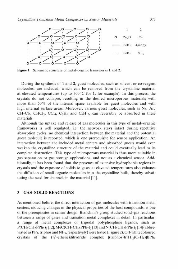
1
Zn 4O
BDC
BDC
2
Cu
4,4-bpy
SiF 6
Figure 1 Schematic structure of metal±organic frameworks 1 and 2.
During the synthesis of 1 and 2, guest molecules, such as solvent or co-reagent
molecules, are included, which can be removed from the crystalline material
at elevated temperatures (up to 300 8C for 1, for example). In this process, the
crystals do not collapse, resulting in the desired microporous materials with
more than 50 % of the internal space available for guest molecules and with
high internal surface areas. Moreover, various guest molecules, such as N2, Ar,
CH2Cl2, CHCl3, CCl4, C6H6 and C6H12, can reversibly be absorbed in these
materials.
Although the uptake and release of gas molecules in this type of metal±organic
frameworks is well regulated, i.e. the network stays intact during repetitive
absorption cycles, no chemical interaction between the material and the potential
guest molecule is reported, which is one prerequisite for sensor application. An
interaction between the included metal centers and absorbed guests would even
weaken the crystalline structure of the material and could eventually lead to its
complete destruction. This type of microporous material is thus more suitable in
gas separation or gas storage applications, and not as a chemical sensor. Add-
itionally, it has been found that the presence of extensive hydrophobic regions in
crystals and the exposure of solids to gases at elevated temperatures also enhance
the diffusion of small organic molecules into the crystalline bulk, thereby substi-
tuting the need for channels in the material [11].
3 GAS±SOLID REACTIONS
As mentioned before, the direct interaction of gas molecules with transition metal
centers, inducing changes in the physical properties of the host compounds, is one
of the prerequisites in sensor design. Bianchini's group studied solid±gas reactions
between a range of gases and transition metal complexes in detail. In particular,
a range of metal complexes of tripodal polyphosphine ligands, such as
P(CH2CH2PPh2)3 [12],MeC(CH2CH2PPh2)3 [13]andN(CH2CH2PPh2)3 [14] (abbre-
viatedasPP3, triphosandNP3, respectively)were tested (Figure2).Off-whitecoloured
crystals of the (Z2-ethene)dihydride complex [(triphos)Ir(H)2(C2H4)]BPh4
Crystalline Transition Metal Complexes as Sensor Materials 377

CoPP
PN
P
N
4
Irreversible reaction withC2H4, H2CO and MeCHO
P
Ir HH
PP
3
Irreversible reaction withC2H4, H2 and CO
Ni PP
P
N
5
NiPP
P
N
CO
6 7
+ NiPP
P
N
C CO O
CO, 1 atmsolid-gas20 8C
N270 8C
BPh4
BPh4
Figure 2 Solid±gas reactions using metal complexes of tripodal phosphine ligands.
(3) reacted with various gases, such as CO, ethene, H2 and ethylene [13]. Analo-
gously, when ethyne or gaseous formaldehyde was passed over purple±red crystals
of the dinitrogen cobalt(II) complex [(PP3)Co(N2)]BF4 (4) (90 8C), irreversible
adduct formation occurred [12]. Solid±gas reactions with 3 and 4 were accompan-
ied by a colour change of the starting materials. Solid±gas reaction between red
crystals of (NP3)Ni (5) and CO (1 atm) at room temperature afforded a yellow
product, consisting of 6 and a new complex, 7 (see Figure 2) [31P cross-polariza-
tion magic angle spinning (CP MAS) NMR and in situ infrared measurements]
[14]. The latter was suggested to be a metastable species in which a free phosphine
arm from the NP3 ligand is located close to the nickel center as a result of the
constraining environment of the crystal lattice.
During these solid±gas reactions, no substantial fragmentation of the exposed
crystals was observed, although the products appear slightly opaque as observed
by cross-polarization microscopy. The absence of fragmentation indicates that the
reaction does not proceed via reaction at the surface, followed by subsequent
breakdown of the crystal to facilitate further reaction at the newly formed surface.
Instead, the reactions take place in the bulk of the crystal, after diffusion of the
gas molecules from the surface to the bulk, which is enhanced by the presence of
the hydrophobic regions in the crystals provided by the PPh2 groups of the
ligands. Furthermore, applying higher (reaction) temperatures (up to 100 8C) fur-
ther accelerated gas diffusion into the crystal. Complexes 3 and 4 are not suitable
as transition metal sensors for the gases mentioned in Figure 2 because of the
irreversible nature of the reported solid±gas reactions. Some of these complexes
were successfully applied as solid transition metal complex catalysts [13]. How-
378 Crystal Design: Structure and Function
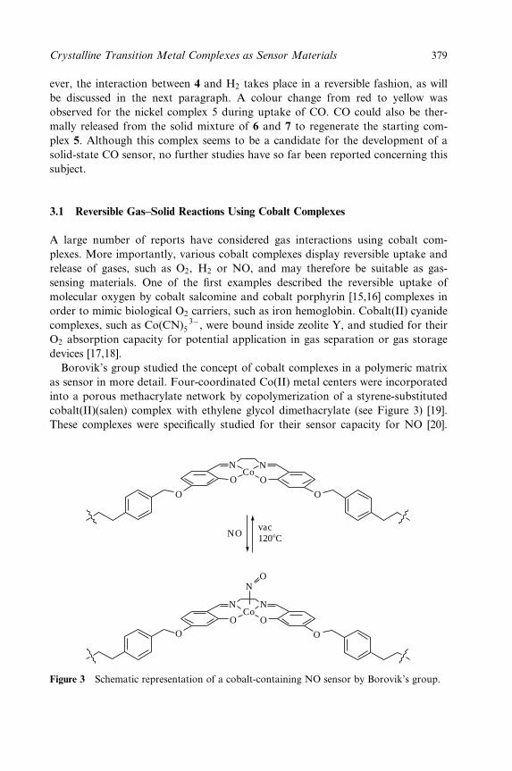
ever, the interaction between 4 and H2 takes place in a reversible fashion, as will
be discussed in the next paragraph. A colour change from red to yellow was
observed for the nickel complex 5 during uptake of CO. CO could also be ther-
mally released from the solid mixture of 6 and 7 to regenerate the starting com-
plex 5. Although this complex seems to be a candidate for the development of a
solid-state CO sensor, no further studies have so far been reported concerning this
subject.
3.1 Reversible Gas±Solid Reactions Using Cobalt Complexes
A large number of reports have considered gas interactions using cobalt com-
plexes. More importantly, various cobalt complexes display reversible uptake and
release of gases, such as O2, H2 or NO, and may therefore be suitable as gas-
sensing materials. One of the ®rst examples described the reversible uptake of
molecular oxygen by cobalt salcomine and cobalt porphyrin [15,16] complexes in
order to mimic biological O2 carriers, such as iron hemoglobin. Cobalt(II) cyanide
complexes, such as Co(CN) 3ÿ5 , were bound inside zeolite Y, and studied for their
O2 absorption capacity for potential application in gas separation or gas storage
devices [17,18].
Borovik's group studied the concept of cobalt complexes in a polymeric matrix
as sensor in more detail. Four-coordinated Co(II) metal centers were incorporated
into a porous methacrylate network by copolymerization of a styrene-substituted
cobalt(II)(salen) complex with ethylene glycol dimethacrylate (see Figure 3) [19].
These complexes were speci®cally studied for their sensor capacity for NO [20].
NN
O O
O O
NCo
O
N
O
O O
NO
NOvac1208C
Co
Figure 3 Schematic representation of a cobalt-containing NO sensor by Borovik's group.
Crystalline Transition Metal Complexes as Sensor Materials 379
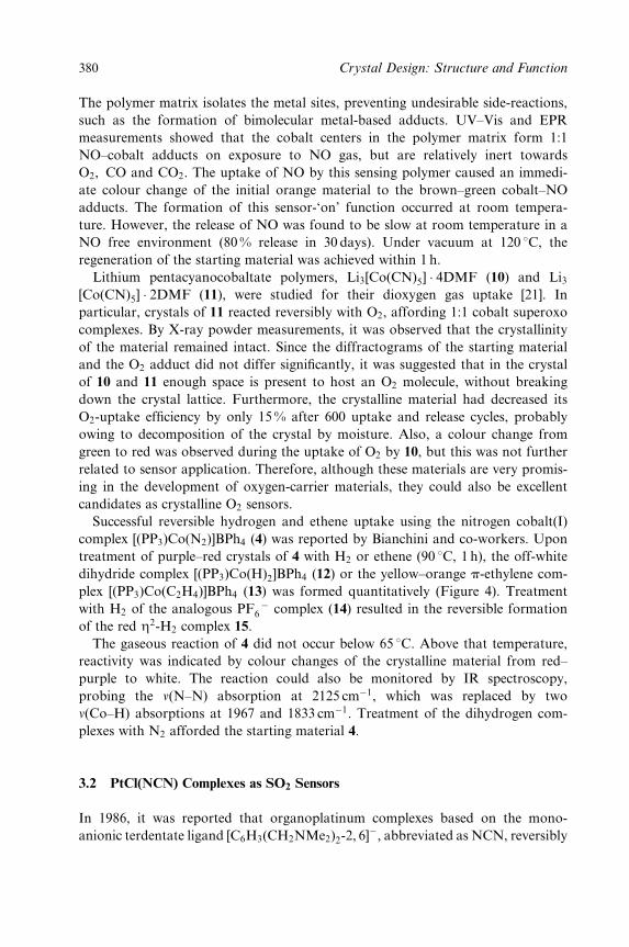
The polymer matrix isolates the metal sites, preventing undesirable side-reactions,
such as the formation of bimolecular metal-based adducts. UV±Vis and EPR
measurements showed that the cobalt centers in the polymer matrix form 1:1
NO±cobalt adducts on exposure to NO gas, but are relatively inert towards
O2, CO and CO2. The uptake of NO by this sensing polymer caused an immedi-
ate colour change of the initial orange material to the brown±green cobalt±NO
adducts. The formation of this sensor-`on' function occurred at room tempera-
ture. However, the release of NO was found to be slow at room temperature in a
NO free environment (80% release in 30 days). Under vacuum at 120 8C, the
regeneration of the starting material was achieved within 1 h.
Lithium pentacyanocobaltate polymers, Li3[Co(CN)5] � 4DMF (10) and Li3[Co(CN)5] � 2DMF (11), were studied for their dioxygen gas uptake [21]. In
particular, crystals of 11 reacted reversibly with O2, affording 1:1 cobalt superoxo
complexes. By X-ray powder measurements, it was observed that the crystallinity
of the material remained intact. Since the diffractograms of the starting material
and the O2 adduct did not differ signi®cantly, it was suggested that in the crystal
of 10 and 11 enough space is present to host an O2 molecule, without breaking
down the crystal lattice. Furthermore, the crystalline material had decreased its
O2-uptake ef®ciency by only 15 % after 600 uptake and release cycles, probably
owing to decomposition of the crystal by moisture. Also, a colour change from
green to red was observed during the uptake of O2 by 10, but this was not further
related to sensor application. Therefore, although these materials are very promis-
ing in the development of oxygen-carrier materials, they could also be excellent
candidates as crystalline O2 sensors.
Successful reversible hydrogen and ethene uptake using the nitrogen cobalt(I)
complex [(PP3)Co(N2)]BPh4 (4) was reported by Bianchini and co-workers. Upon
treatment of purple±red crystals of 4 with H2 or ethene (90 8C, 1 h), the off-white
dihydride complex [(PP3)Co(H)2]BPh4 (12) or the yellow±orange p-ethylene com-
plex [(PP3)Co(C2H4)]BPh4 (13) was formed quantitatively (Figure 4). Treatment
with H2 of the analogous PF ÿ6 complex (14) resulted in the reversible formation
of the red Z2-H2 complex 15.
The gaseous reaction of 4 did not occur below 65 8C. Above that temperature,
reactivity was indicated by colour changes of the crystalline material from red±
purple to white. The reaction could also be monitored by IR spectroscopy,
probing the n(N±N) absorption at 2125 cmÿ1, which was replaced by two
n(Co±H) absorptions at 1967 and 1833 cmÿ1. Treatment of the dihydrogen com-
plexes with N2 afforded the starting material 4.
3.2 PtCl(NCN) Complexes as SO2 Sensors
In 1986, it was reported that organoplatinum complexes based on the mono-
anionic terdentate ligand [C6H3(CH2NMe2)2-2, 6]ÿ, abbreviated as NCN, reversibly
380 Crystal Design: Structure and Function

PP
PP
13
Co CoPP
PP
12
HH
BPh4
P
PP
N
P
N
Co
YBPh4
Co PP
PP
15
H HPF 6
H2
H2
N2
N2
N2
C2H4
4 Y = BPh4
14 Y = PF 6
Figure 4 Reversible reaction of H2 or C2H4 with tripodal polyphosphine cobalt complex 4.
bind SO2 gas in solution (Figure 5) [22]. In this reaction, a stable pentacoordi-
nated platinum center is formed, in which the SO2 molecule is bound via the
S-atom to the platinum center in an Z1-fashion. This reaction also proceeds in the
solid state and is accompanied by an immediate colour change of the colourless
starting material to the bright orange SO2 adduct. The detailed mechanism of the
reversible binding process was studied using density functional theory calculations
and low-temperature experiments [23], which revealed that exchange of SO2 pro-
ceeds via a dissociative mechanism (®rst order in NCN±platinum and zeroth order
in SO2).
N
NN
N
S
Pt Br
+SO2
−SO2
Pt Br
24 Colorless 25 Orange
Figure 5 Bonding of SO2 to NCN±PtBr.
Crystalline Transition Metal Complexes as Sensor Materials 381
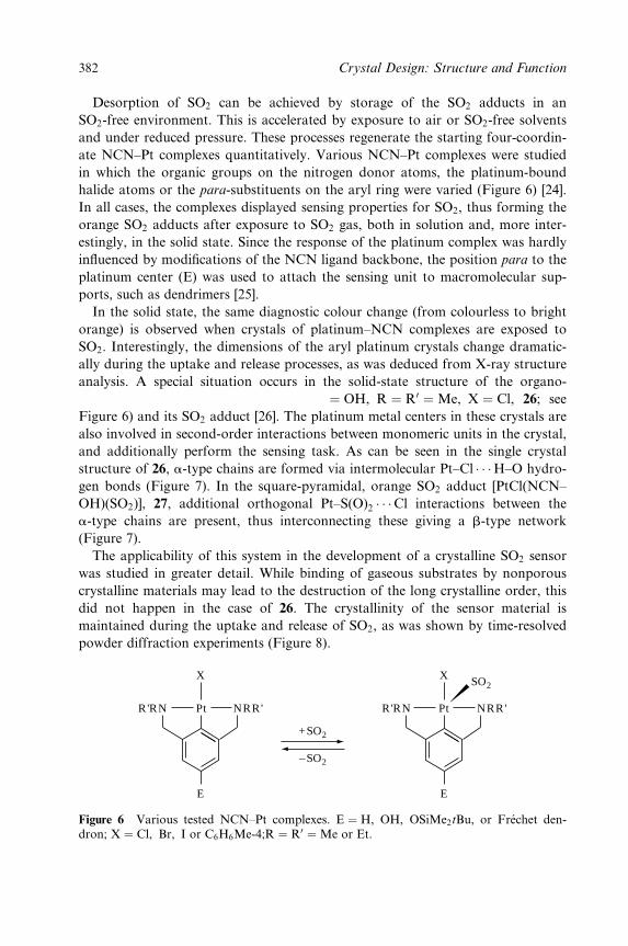
Desorption of SO2 can be achieved by storage of the SO2 adducts in an
SO2-free environment. This is accelerated by exposure to air or SO2-free solvents
and under reduced pressure. These processes regenerate the starting four-coordin-
ate NCN±Pt complexes quantitatively. Various NCN±Pt complexes were studied
in which the organic groups on the nitrogen donor atoms, the platinum-bound
halide atoms or the para-substituents on the aryl ring were varied (Figure 6) [24].
In all cases, the complexes displayed sensing properties for SO2, thus forming the
orange SO2 adducts after exposure to SO2 gas, both in solution and, more inter-
estingly, in the solid state. Since the response of the platinum complex was hardly
in¯uenced by modi®cations of the NCN ligand backbone, the position para to the
platinum center (E) was used to attach the sensing unit to macromolecular sup-
ports, such as dendrimers [25].
In the solid state, the same diagnostic colour change (from colourless to bright
orange) is observed when crystals of platinum±NCN complexes are exposed to
SO2. Interestingly, the dimensions of the aryl platinum crystals change dramatic-
ally during the uptake and release processes, as was deduced from X-ray structure
analysis. A special situation occurs in the solid-state structure of the organo-
platinum complex [PtCl(NCN±OH)] (E � OH, R � R0 �Me, X � Cl, 26; see
Figure 6) and its SO2 adduct [26]. The platinum metal centers in these crystals are
also involved in second-order interactions between monomeric units in the crystal,
and additionally perform the sensing task. As can be seen in the single crystal
structure of 26, a-type chains are formed via intermolecular Pt±Cl � � �H±O hydro-
gen bonds (Figure 7). In the square-pyramidal, orange SO2 adduct [PtCl(NCN±
OH)(SO2)], 27, additional orthogonal Pt±S(O)2 � � �Cl interactions between the
a-type chains are present, thus interconnecting these giving a b-type network
(Figure 7).
The applicability of this system in the development of a crystalline SO2 sensor
was studied in greater detail. While binding of gaseous substrates by nonporous
crystalline materials may lead to the destruction of the long crystalline order, this
did not happen in the case of 26. The crystallinity of the sensor material is
maintained during the uptake and release of SO2, as was shown by time-resolved
powder diffraction experiments (Figure 8).
R'RN Pt NRR' R'RN Pt NRR'
E
X
E
X SO2
+SO2
−SO2
Figure 6 Various tested NCN±Pt complexes. E � H, OH, OSiMe2tBu, or FreÂchet den-dron; X � Cl, Br, I or C6H6Me-4;R � R0 �Me or Et.
382 Crystal Design: Structure and Function
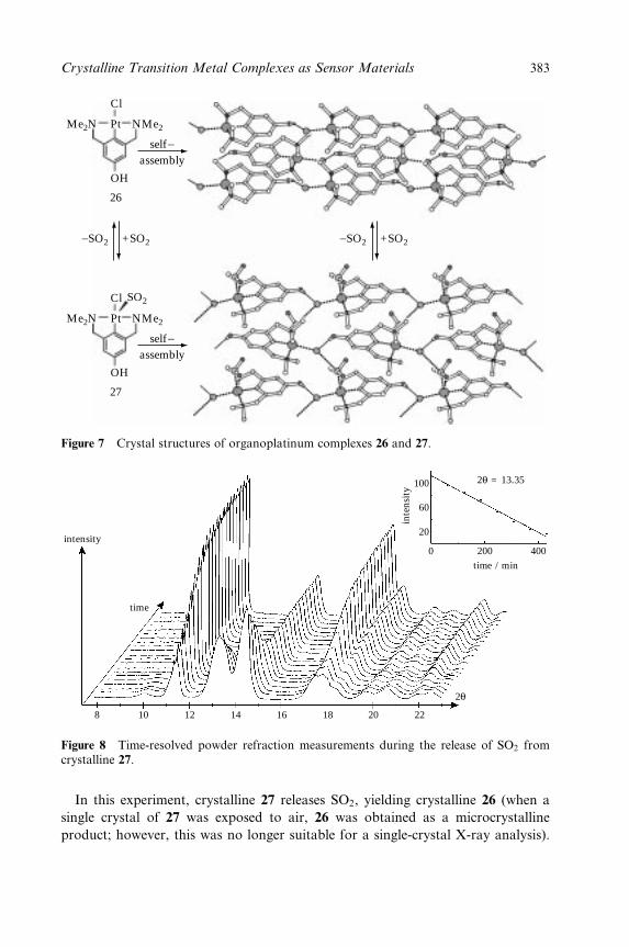
Cl
Pt
OH
Me2N NMe2
26
Cl
Pt
OH
Me2N NMe2
27
self−assembly
self−assembly
−SO2 +SO2−SO2 +SO2
SO2
Figure 7 Crystal structures of organoplatinum complexes 26 and 27.
intensity
time
2θ = 13.35100
60
20
0 200 400
inte
nsit
y
time / min
8 10 12 14 16 18 20 22
2θ
Figure 8 Time-resolved powder refraction measurements during the release of SO2 fromcrystalline 27.
In this experiment, crystalline 27 releases SO2, yielding crystalline 26 (when a
single crystal of 27 was exposed to air, 26 was obtained as a microcrystalline
product; however, this was no longer suitable for a single-crystal X-ray analysis).
Crystalline Transition Metal Complexes as Sensor Materials 383
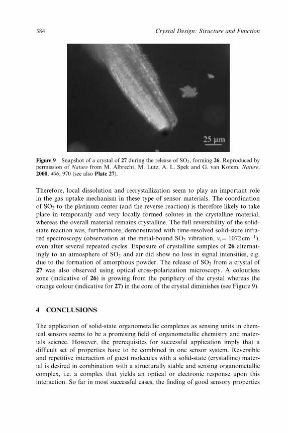
Figure 9 Snapshot of a crystal of 27 during the release of SO2, forming 26. Reproduced bypermission of Nature from M. Albrecht, M. Lutz, A. L. Spek and G. van Kotem, Nature,2000, 406, 970 (see also Plate 27).
Therefore, local dissolution and recrystallization seem to play an important role
in the gas uptake mechanism in these type of sensor materials. The coordination
of SO2 to the platinum center (and the reverse reaction) is therefore likely to take
place in temporarily and very locally formed solutes in the crystalline material,
whereas the overall material remains crystalline. The full reversibility of the solid-
state reaction was, furthermore, demonstrated with time-resolved solid-state infra-
red spectroscopy (observation at the metal-bound SO2 vibration, ns� 1072 cmÿ1),
even after several repeated cycles. Exposure of crystalline samples of 26 alternat-
ingly to an atmosphere of SO2 and air did show no loss in signal intensities, e.g.
due to the formation of amorphous powder. The release of SO2 from a crystal of
27 was also observed using optical cross-polarization microscopy. A colourless
zone (indicative of 26) is growing from the periphery of the crystal whereas the
orange colour (indicative for 27) in the core of the crystal diminishes (see Figure 9).
4 CONCLUSIONS
The application of solid-state organometallic complexes as sensing units in chem-
ical sensors seems to be a promising ®eld of organometallic chemistry and mater-
ials science. However, the prerequisites for successful application imply that a
dif®cult set of properties have to be combined in one sensor system. Reversible
and repetitive interaction of guest molecules with a solid-state (crystalline) mater-
ial is desired in combination with a structurally stable and sensing organometallic
complex, i.e. a complex that yields an optical or electronic response upon this
interaction. So far in most successful cases, the ®nding of good sensory properties
384 Crystal Design: Structure and Function
of an organometallic crystal is based more on serendipity than on (empirical)
prediction. The design of (selective) organometallic sensors, therefore, poses an
interesting, multidisciplinary challenge. To derive selection rules for the designing
process, expertises from organometallic chemistry, crystal engineering and solid-
state chemistry have to join forces. From an organometallic point of view, the
molecular reactivity of concrete complexes has to be translated to solid-state
reactivity. In addition, special features have to be incorporated into metal com-
plexes to ensure the build-up of an open and stable crystalline framework. From
the crystal engineer/solid state point of view, strategies have to be developed for
the construction of crystalline (coordination) networks that contain reactive (or-
gano)metallic sites. Therefore, the research performed in the ®eld of (organomet-
allic) coordination polymers that still contain coordinately unsaturated metal sites
may in the end lead to suitable organometallic sensors.
ACKNOWLEDGEMENTS
The authors thank Drs Martin Albrecht and Martin Lutz and Professor Ton Spek
for the fruitful collaboration on crystalline, organometallic gas sensors.
REFERENCES
1. See, for example, Acc. Chem. Res. 2001, 34(6), special issue on molecular machines.2. See, for example, Acc. Chem. Res. 1998, 31(5), special issue on chemical sensors.3. Crooks, R. M.; Ricco, A. J. Acc. Chem. Res. 1998, 31, 219.4. Nalwa, H. S.; Kakuta, A. Appl. Organomet. Chem. 1992, 6, 645.5. See, for example, (a) Wright, J. D. Inst. Phys. Conf. Ser 1990, 111, 333; (b) Sadaoka,
Y.; Jones, T. A.; Revell, G. S.; GoÈpel, W. J. Mater. Sci. 1990, 25, 5257; (c) GoÈpel, W.Synth. Met. 1991, 41±43, 1087; (d) Guillaud, G.; Simon, J.; Germain, J. P. Coord.
Chem. Rev. 1998, 178±180, 1433.6. (a) Papkovsky, D. B.; Desyaterik, I. V.; Ponomarev, G. V.; Kurochkin, I. N.; Korpela,
T. Anal. Lett. 1995, 28, 2027; (b) Natale, C. D.; Macagnano, A.; Repole, G.; Saggio,G.; D'Amico, A.; Paolesse, R.; Boschi, T. Mater. Sci. Eng. 1998, C5, 209.
7. For a review on transition metal porous solids, see Yaghi, O. M.; Li, H.; Davis, C.;Richardson, D.; Groy, T. L. Acc. Chem. Res. 1998, 31, 474.
8. Zaworotko, M. J. Angew. Chem., Int. Ed. Engl. 2000, 39, 3052.9. (a) Yaghi, O. M.; Li, G.; Li, H. Nature (London) 1995, 378, 703; (b) Eddaoudi, M.; Li,
H.; Yaghi, O. M. J. Am. Chem. Soc. 2000, 122, 1391; (c) Li, H.; Eddaoudi, M.; O'Keeffe,M.; Taghi, O. M. Nature (London) 1999, 402, 276.
10. Noro, S.-I.; Kitagawa, S.; Kondo, M.; Seki, K. Angew. Chem., Int. Ed. Engl. 2000, 39,2082.
11. (a) Siedle, A. R.; Newmark, R. A. Organometallics 1989, 8, 1442; (b) Siedle, A. R.;Newmark, R. A.; Sahyun, M. R. V.; Lyon, P. A.; Hunt, S. L.; Skarjune, R. P. J. Am.
Chem. Soc. 1989, 111, 8346.12. Bianchini, C.; Peruzzini, M.; Zanobini, F. Organometallics 1991, 10, 3415.
Crystalline Transition Metal Complexes as Sensor Materials 385
13. (a) Bianchini, C.; Frediani, P.; Graziani, M.; Kaspar, J.; Meli, A.; Peruzzini, M.; Vizza,F. Organometallics 1993, 12, 2886; (b) Bianchini, C.; Farnetti, E.; Graziani, M.; Kas-par, J.; Vizza, F. J. Am. Chem. Soc. 1993, 115, 1753; (c) Bianchini, C.; Graziani, M.;Kaspar, J.; Meli, A.; Vizza, F. Organometallics 1994, 13, 1165; (d) Bianchini, C.; Meli,A.; Peruzinni, M.; Vizza, F.; Frediani, P.; Herrera, V.; Sanchez-Delgado, R. A. J. Am.
Chem. Soc. 1993, 115, 7505.14. Bianchini, C.; Zanobini, F.; Aime, S.; Gobetto, R.; Psaro, R.; Sordelli, L. Organometal-
lics 1993, 12, 4757.15. Collman, J. P.; Gagne, R. R.; Kouba, J.; Ljusberg-Wahren, H. J. Am. Chem. Soc. 1974,
96, 6800.16. Collman, J. P.; Brauman, J. I.; Doxsee, K. M.; Halbert, T. R.; Hayes, S. E.; Suslick, K.
S. J. Am. Chem. Soc. 1978, 100, 2761.17. Taylor, R. J.; Drago, R. S.; George, J. E. J. Am. Chem. Soc. 1989, 111, 6610.18. Taylor, R. J.; Drago, R. S.; Hage, J. P. Inorg. Chem. 1992, 31, 253.19. Krebs, J. F.; Borovik, A. S. Chem. Commun. 1998, 553.20. Padden, K. M.; Krebs, J. F.; MacBeth, C. E.; Scarrow, R. C.; Borovik, A. S. J. Am.
Chem. Soc. 2001, 123, 1072.21. Ramprasad, D.; Pez, G. P.; Toby, B. H.; Markley, T. J.; Pearlstein, R. M. J. Am.
Chem. Soc. 1995, 117, 10694.22. Terheijden, J.; van Koten, G.; Mul, W. P.; Stufkens, D. J.; Muller, F.; Stam, C. H.
Organometallics 1986, 5, 519.23. Albrecht, M.; Gossage, R. A.; Frey, U.; Ehlers, A. W.; Baerends, E. J.; Merbach, A.
E.; van Koten, G. Inorg. Chem. 2001, 40, 850.24. Albrecht, M.; Gossage, R. A.; Lutz, M.; Spek, A. L.; van Koten, G. Chem. Eur. J.
2000, 6, 1431.25. (a) Albrecht, M.; Gossage, R. A.; Spek, A. L.; van Koten, G. Chem. Commun. 1998,
1003; (b) Albrecht, M.; van Koten, G. Adv. Mater. 1999, 11, 171; (c) Albrecht, M.;Hovestad, N. J.; Boersma, J.; van Koten, G. Chem. Eur. J. 2001, 7, 1289.
26. (a) Albrecht, M.; Lutz, M.; Schreurs, A. M. M., Lutz, E. T. H.; Spek, A. L.; vanKoten, G. J. Chem. Soc., Dalton Trans. 2000, 3797; (b) Albrecht, M.; Lutz, M.; Spek,A. L.; van Koten, G. Nature (London) 2000, 406, 970.
386 Crystal Design: Structure and Function
Cumulative Author Index
This index comprises the names of contributors to Volumes 1±7 of Perspectives in
Supramolecular Chemistry.
Akashi, Ken-ichirou, Observation of a
Variety of Giant Vesicles under an
Optical Microscope, 6, 45; see also
Miyata, Hidetake, 6, 319.
Alargova,Rossitsa, G., seeBivas, Isak, 6, 207.
Albrecht, Anne-Marie, see Dannenmuller,
Olivier, 6, 385.
Angelova, Miglena, I., Liposome
Electroformation, 6, 27; see also
Kinnunen, Paavo, K., 6, 273.
Arakawa, Kenji, see Dannenmuller, Olivier,
6, 385.
Atwood, Jerry L., Very Large
Supramolecular Capsules Based on
Hydrogen Bonding, 7, 153.
Bacri, Jean-Claude, see Sandre, Olivier, 6,
169.
Barbour, Leonard, J., see Atwood, Jerry L.,
7, 153.
Bassereau, Patricia, see Manneville, Jean-
Baptiste, 6, 351.
Beginn, Uwe, Supramolecular Structures
with Macromolecules, 4, 89.
Bell, Ian M., see Hilvert, Donald, 1, 73.
Benkovic, S. J., Macrocycles and Antibodies
as Catalysts, 1, 149.
Bernard, Anne-Laure, see Guedeau-
Boudeville, Marie-Alice, 6, 341.
Barawkar, Dinesh, A. see Ganesh, Krishna
N., 3, 263.
Biradha, Kumar, Layered Materials by
Design: 2D Coordination Polymeric
Networks Containing Large Cavities/
Channels, 7, 211.
Bivas, Isak, Free Energy of a Fluctuating
Vesicle. In¯uence of the Fluctuations on
the Laplace Law, 6, 93; see also
Mechanical Properties of Lipid Bilayers
Containing Grafted Lipids, 6, 207.
Blanc, Sylvie, see Dannenmuller, Olivier, 6,
385.
Bothorel, Pierre, see Bivas, Isak, 6, 207.
Bowden, Ned, see Issacs, Lyle, 4, 1.
Bradley, Jean-Claude, see Guedeau-
Boudeville, Marie-Alice, 6, 341.
Bradshaw, Jerald, S., see Izatt, Reed, M., 4,
225.
Braga, Dario, Polymorphism, Crystal
Transformations and Gas-Solid
Reactions, 7, 325.
Brammer, Lee, Hydrogen Bonds in Inorganic
Chemistry: Application to Crystal
Design, 7, 1.
Crystal Design: Structure and Function. Volume 7Edited by Gautam R. Desiraju
Copyright 2003 John Wiley & Sons, Ltd.ISBN: 0-470-84333-0
Bruce, Duncan, W., MetallomesogensÐ
Supramolecular Organization of Metal
Complexes in Fluid Phases, 5, 285.
Bruening, Ronald, L., see Izatt, Reed, M.,
4, 225.
Burkholder, Eric, see Finn, Robert, C., 7,
241.
Camuil, ValeÂrie, see Sandre, Olivier, 6, 169.
Cebers, Andrejs, see Sandre, Olivier, 6, 169.
Chambron, Jean-Claude, Rotaxanes: From
Random to Transition Metal-templated
Threading of Rings at the Molecular
Level, 5, 225.
Chandaroy, Parthapratim, see Hui, Sek
Wen, 6, 231.
Chang, Ning-Leh, see Davis, Raymond E.,
2, 63.
Chin, Donovan, N., see Issacs, Lyle, 4, 1.
Collinson, Simon, see Bruce, Duncan, W.,
5, 285.
Cramer, Friedrich, Emil Fischer's Lock-and-
Key Hypothesis after 100 Years ±
Towards a Supracellular Chemistry, 1,
1.
Czarnik, Anthony, W., Chemosensors:
Synthetic Receptors in Analytical
Sensing Applications, 4, 177.
Dance, Ian, Supramolecular Organic
Chemistry, 2, 137.
Dannenmuller, Olivier, Membrane
Properties of Archaeal Phospholipids:
Effects of Macrocyclization, 6, 385.
Davis, Raymond E., Molecular Shape as a
Design Criterion in Crystal Engineering,
2, 63.
De Cian, AndreÂ, see Martz, Julien, 7, 177.
Decurtins, Silvio, see Pilkington, Melanie,
7, 275.
Demleitner, Bernhard, see Saalfrank, Rolf,
W., 5, 1.
Desiraju, Gautam R., Crystal Engineering
and Molecular RecognitionÐTwin Facets
of Supramolecular Chemistry, 2, 31.
Dietrich, Christian, see Dimova, Rumiana,
6, 221.
Dimova, Rumiana, Motion of Particles
Attached to Giant Vesicles: Falling Ball
Viscosimetry and Elasticity
Measurements on Lipid Membranes, 6,
221.
DoÈbereiner, Hans-GuÈnther, Fluctuating
Vesicle Shapes, 6, 149; see also Xu,
Liyu, 6, 181; Petrov, Peter G., 6, 335.
Doi, Toshifusa, see Imai, Masanao, 6, 361.
Dunnitz, Jack D., Thoughts on Crystals as
Supermolecules, 2, 1.
Eguchi, Tadashi, see Dannenmuller, Olivier,
6, 385.
Fabbrizzi, Luigi, Fluorescent Sensors for and
with Transition Metals, 5, 93.
Fagan, Paul J., Molecular Engineering of
Crystals by Electrostatic Templating, 2,
107.
Finn, Robert, C., The Construction of One-,
Two-, and Three-Dimensional Organic±
Inorganic Hybrid Materials from
Molecular Building Blocks, 7, 241.
Fischer, Aline, Formation of Giant Vesicles
from Different Kinds of Lipids Using the
Electrothermal Method, 6, 37; see also
Oberholzer, Thomas, 6, 285.
Fredricks, John R., Metal Template Control
of Self-Assembly in Supramolecular
Chemistry, 3, 1.
Fujita, Makota, see Biradha, Kumar, 7, 211.
Ganesh, Krishna N., Synthetic Control of
DNA Triplex Structure Through
Chemical Modi®cations, 3, 263.
Gangl, Susanne, Molecular Organization on
Giant Unilamellar Vesicles, 6, 379.
Gerbeaud, Claire, see MeÂleÂard, Philippe, 6,
185.
Glusker, Jenny P., The Protein as a
Supermolecule: The Architecture of a
(ba)8 Barrel, 2, 235.
Goto, Ayako, Dynamic Aspects of Fatty
Acid Vesicles: pH-induced Vesicle±
Micelle Transition and Dilution-induced
Formation of Giant Vesicles, 6, 261.
388 Cumulative Author Index

Goto, Rensuke, see Goto, Ayako, 6, 261.
Graf, Ernest, see Martz, Julien, 7, 177.
Grepioni, Fabrizia, see Braga, Dario, 7, 325.
Guedeau-Boudeville, Marie-Alice, Changes
in the Morphology of Giant Vesicles
Under Various Physico-chemical
Stresses, 6, 341.
Hamilton, Andrew, D., see Fredricks, John
R., 3, 1.
Hanessian, Stephen, see Saladino, Raffaele,
7, 77.
Hosseini, Mir Wais, see Martz, Julien, 7, 177.
Helfrich, Wolfgang, Bending Elasticity of
Fluid Membranes, 6, 51; see also
KloÈsgen, Beate, 6, 243; see also
Thimmel, Johannes, 6, 253.
Hilvert, Donald, New Biocatalysts via
Chemical Modi®cations, 1, 73.
Holopainen, Juha, M. see Kinnunen,
Paavo, K., 6, 273.
Horovitz, Ammon, see Katchalski-Katzir,
Ephraim, 1, 25.
Hui, Sek Wen, Control of Fusion Between
Giant Vesicles, 6, 231.
Imae, Toyoko, see Goto, Ayako, 6, 261.
Imai, Masanao, Entrapment of Proteins in
Soybean Phosphatidycholine Vesicles, 6,
361.
Issacs, Lyle, Self-Assembling Systems on
Scales from Nanometers to Millimeters:
Design and Discovery, 4, 1.
Itoh, Horoyasu, see Akashi, Ken-ichirou, 6,
45.
Izatt, Reed, M., Ion Separations in
Membrane and Solid Phase Extraction
Systems, 4, 225.
Jerga, Agoston, see Atwood, Jerry L., 7, 153.
Jullien, Ludovic, see Guedeau-Boudeville,
Marie-Alice, 6, 341.
Kakinuma, Katsumi, See, Dannenmuller,
Olivier, 6, 385.
Katchalski-Katzir, Ephraim, Molecular
recognition in Biology: Models for
Analysis of Protein±Ligand Interactions,
1, 25.
Kim, Kimoon, Self-Assembly of Interlocked
Structures with Cucurbituril Metal Ions
and Metal Complexes, 5, 371.
Kinnunen, Paavo, K., Giant Liposomes as
Model Biomembranes for Roles of
Lipids in Cellular Signalling, 6, 273.
Kinosita, Kazuhiko, Jr., see Akashi, Ken-
ichirou, 6, 45; see also Miyata,
Hidetake, 6, 319.
Klein Gebbink, Robertus, J.M., see Meijer,
Michel, D., 7, 375.
KloÈsgen, Beate, Membrane Roughness and
Dispersive Phase as Effects of Higher-
order Bending in Fluid Membranes, 6,
243; see also Thimmel, Johannes, 6,
253.
KoÈhler, Gottfried, see Gangl, Susanne, 6,
379.
Krishnamohan Sharma, C.V., see Desiraju,
Gautam, R., 2, 31.
Kuboi, Ryoichi, see Shimanouchi,
Toshinori, 6, 369.
Kuhn, Hans, A Model of the Origin of Life
and Perspectives in Supramolecular
Engineering, 1, 247.
Kumar, Vaijayanti, A. see Ganesh, Krishna
N., 3, 263.
Lahav, Meir, Lock-and-Key Processes at
Crystalline Interfaces: Relevance to the
Spontaneous Generation of Chirality, 1,
173.
Lancet, Doron, see Katchalski-Katzir,
Ephraim, 1, 25.
Lasic, Danilo, D. Giant Vesicles: A
Historical Introduction, 6, 11.
Lehn, Jean-Marie, Perspectives in
Supramolecular Chemistry ± From the
Lock-and-Key Image to the Information
Paradigm, 1, 307.
Leiserowitz, Leslie, see Lahav, Meir, 1, 173.
LeÂvy, Daniel, see Manneville, Jean-Baptiste,
6, 351.
Licchelli, Maurizio, see Fabbrizzi, Luigi, 5,
93.
Cumulative Author Index 389

Lugtenberg, Ronny J.W., Selective Ion
Recognition with Durable Sensors, 4, 193.
Luisi, Pier Luigi, Why Giant Vesicles?, 6, 3;
see also Fischer, Aline, 6, 37.
Lukas, Arno, see Gangl, Susanne, 6, 379.
Maitra, Uday, A Survey of Supramolecular
Chemistry (1993±1994), 3, 41.
Manneville, Jan-Baptiste, Magni®cation of
Shape Fluctuations of Active Giant
Unilamellar Vesicles, 6, 351.
Marriott, Gerard, see Miyata, Hidetake,
6, 319.
Martz, Julien, Molecular Tectonics:
Molecular Networks Based on Inclusion
Processes, 7, 177.
Mayer, Bernd, see Gangl, Susanne, 6, 379.
Mayrhofer, Peter, see Gangl, Susanne, 6, 379.
Meijer, E.W., see van Genderen, Marcel
H.P., 4, 47.
Meijer, Michel, D., Solid±Gas Interactions
Between Small Gaseous Molecules and
Transition Metals in the Solid State.
Toward Sensor Applications, 7, 375.
MeÂleÂard, Philippe, Electromechanical
Properties of Model Membranes and
Giant Vesicle Deformations, 6, 185; see
also Bivas, Isak, 6, 207.
MeÂnager, Christine, see Sandre, Olivier, 6,
169.
Mitov, Marin, D., see MeÂleÂard, Philippe, 6,
185; see also Bivas, Isak, 6, 207.
Miyata, Hidetake, see Akashi, Ken-ichirou,
6, 45; see also Cell deformation
Mechanisms Studied with
Miyata, Hidetake (continued) Actin-
containing Giant Vesicles, a Cell-
mimicking System., 6, 319.
Mody, Tarak, D., Porphyrin- and Expanded
Porphyrin-Based Diagnostic and
Therapeutic Agents, 4, 245.
MoÈller, Martin, see Beginn, Uwe, 4, 89.
Momenteau, Michel., Models of
Hemoprotein Active Sites, 3, 155.
Nagayama, Kazuhito, see Imai, Masanao,
6, 361.
Nakatani, Yoichi, see Dannenmuller,
Olivier, 6, 385.
Needham, David, Use of Micropipet
Manipulation Techniques to Measure
the Properties of Giant Lipid Vesicles,
6, 103.
Nishiyama, Shuji, see Miyata, Hidetake, 6,
319.
Nomura, Shin-ichirou, Giant Phospholipid
Vesicles Entrapping Giant DNA, 6, 313.
Oberholzer, Thomas, see, Fischer, Aline, 6,
37; see also Microinjection of
Macromolecules in Giant Vesicles
Prepared by Electroformation, 6, 285.
Ohki, Kazuo, see Miyata, Hidetake, 6, 319.
Osaki, Nobukazu, see Imai, Masanao, 6, 361.
Ourisson, Guy, see Dannenmuller, Olivier,
6, 385.
Pallavicini, Piersandro, see Fabbrizzi, Luigi,
5, 93.
Parodi, Luisa, see Fabbrizzi, Luigi, 5, 93.
Perkins, Meghan, see Hui, Sek Wen, 6, 231.
Petrov, Peter G., Light-Induced Shape
Transitions of Giant Vesicles, 6, 335.
Pilkington, Melanie, A Rational Approach
for the Self-Assembly of Molecular
Building Blocks in the Field of
Molecule-Based Magnetism, 7, 275.
Popovitz-Biro,Ronit, seeLahav,Meir,1, 173.
Pott, Tanja, See MeÂleÂard, Philippe, 6, 185.
Pouligny, Bernard, see Dimova, Rumiana,
6, 221.
Prost, Jacques, See Manneville, Jean-
Baptiste, 6, 351.
Prost, JeroÃme, see Sandre, Olivier, 6, 169.
Provent, Christophe, The Chirality of
Polynuclear Transition Metal
Complexes, 5, 135.
Rapp, Gert, see Thimmel, Johannes, 6, 253.
Real, Jose Antonio, Bistability in Iron (II)
Spin-Crossover Systems: A
Supramolecular Function, 5, 53.
Rebek Jr, Julius, see Wintner, Edward A.,
3, 225.
390 Cumulative Author Index
Reinhoudt, D.N., see Lugtenberg, R.J.W.,
4, 193.
RuÈnzler, Dominik, see Gangl, Susanne, 6,
379.
Saalfrank, Rolf, W., Ligand and Metal
Control of Self-Assembly in
Supramolecular Chemistry, 5, 1.
Saladino, Raffaele, Molecular Recognition
and Self-Assembly Between Amines and
Alcohols (Supraminols), 7, 77.
Sandre, Olivier, Oblate±Prolate Transition
of Ellipsoidal Magnetoliposomes:
Experiments showing an Anisotropic
Spontaneous Curvature, 6, 169.
Scrimin, Paolo., Control of Reactivity in
Aggregates of Amphiphilic Molecules, 3,
101.
Seifert, Udo, Giant Vesicles: a Theoretical
Perspective, 6, 71.
Sessler, Jonathan, L., see Mody, Tarak, D.,
4, 245.
Shimanouchi, Toshinori, Study on Stress-
mediated Behavior and Preparation of
Giant Vesicles, 6, 369.
Singh, Alok, see Guedeau-Boudeville,
Marie-Alice, 6, 341.
Smithrud, D.B., see Benkovic, S.J., 1, 149.
Stark, Susaane, see Gangle, Susanne, 6, 379.
Suzuki, Akihiro, see Goto, Ayako, 6, 261.
Taglietti, Angelo, see Fabbrizzi, Luigi, 5, 93.
Tanaka, Hikaru, see Imai, Masanao, 6, 361.
Thimmel, Johannes, Swelling and
Separation of DOPC Multilayer
Systems, 6, 253.
Thurner,Caroline, seeGangl,Susanne,6, 379.
Umakoshi, Hiroshi, see Shimanouchi,
Toshinori, 6, 369.
van Genderen, Marcel H.P., Dendritic
Architectures, 4, 47.
van Koten, Gerard, see Meijer, Michel, D.,
7, 375.
Vitkova, Victoria, see Bivas, Isak, 6, 207
Vlassov, V.V., Oligonucleotides:
Superspeci®c Ligands for Targeting
Nucleic Acids and Proteins and
Development of Molecular Devices, 1, 89.
Walde, Peter, see Fischer, Aline, 6, 37; see
also Goto, Ayako, 6, 261; Enzymatic
Reactions in Giant Vesicles, 6, 297.
Ward, Michael, D., see Fagan, Paul J., 2,
107.
Waser, JuÈrg, see Kuhn, Hans, 1, 247.
Weissbuch, Isabelle, see Lahav, Meir, 1, 173.
Whitesell, James, K., see Davis, Raymond
E., 2, 63.
Whitesides, George, M., see Issacs, Lyle, 4, 1.
Williams, Alan, F., see Provent, Christophe,
5, 135.
Winpenny, Richard E.P., Design and
Serendipity in the Synthesis of
Polymetallic Complexes of the 3d-
Metals, 5, 193.
Winterhalter, Mathias, see Bivas, Isak, 6,
207.
Wintner, Edward A., Recent Developments
in the Design of Self-Replicating
Systems, 3, 225.
Wong, Man-Shing, see Davis, Raymond E.,
2, 63.
Xia, Younan., see Issacs, Lyle 4, 1.
Xu, Liyu, Micromanipulation of Tubular
Vesicles, 6, 181.
Yamazaki, Koiji, see Goto, Ayako, 6, 261.
Yoon, Juyong, see Czarnik, Anthony, W.,
4, 177.
Yoshikawa, Kenichi, see Nomura, Shin-
ichirou, 6, 313.
Yoshioka, Hisashi, see Goto, Ayako, 6, 261.
Zhelev, Doncho, see Needham, David, 6,
103.
Zubieta, Jon, A., see Finn, Robert, C., 7,
241.
Cumulative Author Index 391
Cumulative Title Index
This index comprises the titles and authors of all chapters appearing in Volumes 1±7 of
Perspectives in Supramolecular Chemistry
A Model of the Origin of Life and
Perspectives in Supramolecular
Engineering (Kuhn and Waser) 1,
247.
A Rational Approach for the Self-Assembly
of Molecular Building Blocks in the
Field of Molecule-Based Magnetism
(Melanie Pilkington and Silvio
Decurtins) 7, 275
A Survey of Supramolecular Chemistry
(1993±1994) (Maitra) 3, 41.
Bending Elasticity of Fluid Membranes
(Helfrich) 6, 51.
Bistability in Iron (II) Spin-Crossover
Systems: A Supramolecular Function
(Real) 5, 53.
Cell Deformation Mechanisms Studied with
Actin-containing Giant Vesicles, a Cell-
mimicking System (Miyata, Ohki,
Marriott, Nishiyama, Akashi and
Kinosita) 6, 319.
Changes in the Morphology of Giant Vesicles
Under Various Physico-chemical
Stresses (Guedeau-Boudeville, Bernard,
Bradley, Singh and Jullien) 6, 341.
Chemosensors: Synthetic Receptors in
Analytical Sensing Applications
(Czarnik and Yoon) 4, 177.
Control of Fusion Between Giant Vesicles
(Hui, Perkins and Chandaroy) 6, 231.
Control of Reactivity in Aggregates of
Amphiphilic Molecules (Scrimm) 3, 101.
Crystal Engineering and Molecular
RecognitionÐTwin Facets of
Supramolecular Chemistry (Desiraju
and Krishnamoran Sharma) 2, 31.
Dendritic Architectures (van Genderen and
Meijer) 4, 47.
Design and Serendipity in the Synthesis of
Polymetallic Complexes of the 3d-
Metals (Winpenny) 5, 193.
Dynamic Aspects of Fatty Acid Vesicles:
pH-induced Vesicle±Micelle Transition
and Dilution-induced Formation of
Giant Vesicles (Goto, Suzuki, Yoshioka,
Goto, Imae, Yamazaki and Walde) 6,
261.
Emil Fischer's Lock-and-Key Hypothesis
after 100 Years ± Towards a
Supracellular Chemistry (Cramer) 1, 1.
Crystal Design: Structure and Function. Volume 7Edited by Gautam R. Desiraju
Copyright 2003 John Wiley & Sons, Ltd.ISBN: 0-470-84333-0
Entrapment of Proteins in Soybean
Phosphatidycholine Vesicles (Imai,
Nagayama, Tanaka, Osaki and Doi) 6,
361.
Enzymatic Reactions in Giant Vesicles
(Walde) 6, 297.
Fluorescent Sensors for and with
Transition Metals (Fabrizzi,
Licchelli, Pallavicini, Parodi and
Tagliettei) 5, 93
Formation of Giant Vesicles from Different
Kinds of Lipids Using the
Electroformation Method (Fischer,
Luisi, Oberholzer and Walde) 6, 37
Free Energy of a Fluctuating Vesicle.
In¯uence of the Fluctuations on the
Laplace Law (Bivas) 6, 93
Giant Liposomes as Model Biomembranes
for Roles of Lipids in Cellular
Signalling (Kinnunen, Holopainen and
Angelova) 6, 273
Giant Phospholipid Vesicles Entrapping
Giant DNA (Nomura and Yoshikawa)
6, 313
Giant Vesicles: A Historical Introduction
(Lasic) 6, 11
Giant Vesicles: a Theoretical Perspective
(Seifert) 6, 71
Hydrogen Bonds in Inorganic Chemistry:
Application to Crystal Design (Lee
Brammer) 7, 1
Ion Separations in Membrane and Solid
Phase Extraction Systems (Izatt,
Bradshaw and Bruening) 4, 225
Layered Materials by Design: 2D
Coordination Polymeric Networks
Containing Large Cavities/Channels
(Kumar Biradha and Makoto Fujita) 7,
211
Ligand and Metal Control of Self-Assembly
in Supramolecular Chemistry
(Saalfrank and Demleitner) 5, 1
Light-induced Shape Transitions of Giant
Vesicles (Petrov and DoÈbereiner) 6, 335
Liposome Electroformation (Angelova) 6,
27
Lock-and-Key Processes at Crystalline
Interfaces: Relevance to the
Spontaneous Generation of Chirality
(Weissbuch, Popovitz-Biro, Leiserowitz
and Lahav) 1, 173
Macrocycles and Antibodies as Catalysts
(Smithrud and Benkovic) 1, 149
Magni®cation of Shape Fluctuations of
Active Giant Unilamellar Vesicles
(Manneville, Bassereau, LeÂvy and
Prost) 6, 351
Membrane Properties of Archaeal
Phospholipids: Effects of
Macrocyclization (Dannenmuller,
Nakatani, Ourisson, Arakawa, Eguchi,
Kakinuma, Blanc and Albrecht) 6, 385
Membrane Roughness and Dispersive
Phase as Effects of Higher-order
Bending in Fluid Membranes (KloÈsgen
and Helfrich) 6, 243
MetallomesogensÐSupramolecular
Organization of Metal Complexes in
Fluid Phase (Collison and Bruce) 5, 285
Metal Template Control of Self-Assembly
in Supramolecular Chemistry
(Fredericks and Hamilton) 3, 1
Microinjection of Macromolecules in Giant
Vesicles Prepared by Electroformation
(Oberholzer and Fischer) 6, 285
Models of Hemoprotein Active Sites
(Momenteau) 3, 155
Molecular Engineering of Crystals by
Electrostatic Templating (Fagan and
Ward) 2, 107
Molecular Organization on Giant
Unilamellar Vesicles (Gangl, Stark,
Mayrhofer, RuÈnzler, Thurner, Lukas,
Mayer and KoÈhler) 6, 379
Molecular Recognition and Self-Assembly
Between Amines and Alcohols
(Supraminols) (Raffaele Saladino and
Stephen Hanessian) 7, 77
394 Cumulative Title Index
Molecular Recognition in Biology: Models
for Analysis of Protein±Ligand
Interactions (Lancet, Horovitz and
Katchalski-Katzir) 1, 25
Molecular Shape as a Design Criterion in
Crystal Engineering (Davis, Whitesell,
Wong and Chang) 2, 63
Molecular Tectonics: Molecular Networks
Based on Inclusion Processes (Julien
Martz, Ernest Graf, Andre De Cian and
Mir Wais Hosseini) 7, 177
Motion of Particles Attached to Giant
Vesicles: Falling Ball Viscosimetry and
Elasticity Measurements on Lipid
Membranes (Dimova, Dietrich and
Pouligny) 6, 221
New Biocatalysts via Chemical
Modi®cations (Bell and Hilvert) 1, 73
Observation of a Variety of Giant Vesicles
under an Optical Microscope (Akashi,
Kinosita, Miyata, and Itoh) 6, 45
Oligonucleotides: Superspeci®c Ligand for
Targeting Nucleic Acids and Proteins
and Development of Molecular
Devices (Vlassov) 1, 89
Perspectives in Supramolecular Chemistry ±
From the Lock-and-Key Image to the
Information Paradigm (Lehn) 1, 307
Polymorphism, Crystal Transformations
and Gas±Solid Reactions (Dario Braga
and Fabrizia Grepioni) 7, 325
Porphyrin- and Expanded Porphyrin-Based
Diagnostic and Therapeutic Agents
(Mody and Sessler) 4, 245
Recent Developments in the Design of Self-
Replicating Systems (Wintner and
Rebek Jr) 3, 225
Rotaxanes: From Random to Transition
Metal-Templated Threading of Rings at
the Molecular Level (Chambron) 5, 225
Selective Ion Recognition with Durable
Sensors (Lugtenberg and Reinhoudt) 4,
193
Self-Assembling Systems on Scales from
Nanometers to Millimeters: Design and
Discovery (Issacs, Chin, Bowden, Xia
and Whitesides) 4, 1
Self-Assembly of Interlocked Structures
with Cucurbituril Metal Ions and
Metal Complexes (Kim) 5, 371
Solid±Gas Interactions Between Small
Gaseous Molecules and Transition
Metals in the Solid State. Toward
Sensor Applications (Michel D.
Meijer, Robertus J. M. Klein Gebbink
and Gerard van Koten) 7, 375
Study on Stress-mediated Behavior and
Preparation of Giant Vesicles
(Shimanouchi, Umakoshi and Kuboi) 6,
369
Supramolecular Structures with
Macromolecules (Beginn and MoÈller)
4, 89
Swelling and Separation of DOPC
Multilayer Systems (Thimmel, KloÈsgen,
Helfrich and Rapp) 6, 253
Synthetic Control of DNA Triplex Structure
Through Chemical Modi®cations
(Ganesh, Kumar and Barawkar) 3, 263
The Chirality of Polynuclear Transition
Metal Complexes (Provent and
Williams) 5, 135
The Construction of One-, Two- and Three-
Dimensional Organic±Inorganic
Hybrid Materials from Molecular
Building Blocks (Robert C. Finn, Eric
Burkholder and Jon A. Zubieta) 7, 241
The Protein as a Supermolecule: The
Architecture of a (ba)8 Barrel (Glusker)
2, 235
Thoughts on Crystals as Supermolecules
(Dunitz) 2, 1
Very Large Supramolecular Capsules Based
on Hydrogen Bonding (Jerry L. Atwood,
Leonard J. Barbour and Agoston Jerga)
7, 153
Why Giant Vesicles? (Luisi) 6, 3
Cumulative Title Index 395

Index
absorption
by coordination comp1ound networks,
233, 235, 237, 377, 379±380
by hydrogen-bonded networks, 60±62
see also gas±solid interactions
abundance of hydrogen bonds, 10±11, 52
acceptors, hydrogen-bond, see hydrogen-
bond acceptors
acid±base heterogeneous reactions, 362±364
alcohol±amine self-assemblages, see
amine±alcohol self-assemblages
alcohol-based ligands, in hydrogen-bonded
networks, 12, 46±48
aldehyde±amine heterogeneous reactions,
363
alkylamide gelling agents, 142±143
alkylenediphosphonate bridges, 251±264,
266±269
C-alkylpyrogallol[4]arene assemblages,
162±165
alkyne ligands, 55
allyl groups, as connectors in inclusion
compounds, 195, 196±198
amidic hydrogen bonding, 77±78
amido-bearing ligands, 50±51
amine±alcohol self-assemblages, 78±80
aminocavitols, 124±129
applications, 140±145
helical, 101±124, 134±140
hydrogen bonding in, 78±80, 146
selectivity, 133±140
supermolecular architecture, 81±101
supramolecular chiron concept, 129±133
amine±aldehyde heterogeneous reactions,
363
amino alcohols, 145, 124±129
4-aminobiphenyl-4±ol, 85±86
aminocavitols, 124±129
3-amino-4-nitrobenzyl alcohol polymorphs,
87
aminophenols, 82, 85±87
ammonia±acid heterogeneous reactions,
362±363
amorphous phases, 330, 337, 342
amphoteric gas traps, 364±366
anisole host molecules in koiland cavities,
189
anisotropy, magnetic, 291, 292±293, 299
Archimedean solid geometry, 154, 156±157,
159±160, 165
arseniates, metallocenium hexa¯uoro-, 354,
357±359
arsonate in organic hybrid materials,
265±266
assembling cores, 178, 181
aurophilic interactions, 24, 38
4,40-azobipyridine ligands, 217
B±N-bonded networks, 60
benzene, in coordination polymer networks,
218±219, 221±222, 224±227
benzidine±alcohol complexes, 84, 85±86
Crystal Design: Structure and Function. Volume 7Edited by Gautam R. Desiraju
Copyright 2003 John Wiley & Sons, Ltd.ISBN: 0-470-84333-0
benzoic acid ligands, 48
bifunctionality in organic±inorganic hybrid
crystals, 318±319
2,20-biimidazoleate ligands, 30±31
bilayer networks, 230±231, 233
1,10-bi-2±naphthol, 132
biological capsules, 153
4,40-biphenol±calix[4]arene complex,
101±103
4,40-bipyridine, in skewed molecular bricks,
167±171
4,40-bipyridinium anions, 13, 18
2,20-bipyridyl ligands
in 3D oxalate-bridged networks, 306, 312,
314±315, 316±317
in cyanometallate clusters, 290±291
in molybdophosphate organic hybrid
materials, 251±252, 256, 258±259,
262±264, 266±269
4,40-bipyridyl ligands
in coordination polymer networks,
213±216, 222±223, 226±227, 229, 232,
233
in hydrogen-bonded networks, 12, 34±35,
41, 42±43
bipyridyl±1,1,3,3-tetraphenyldisiloxane-1,
3-diol±amine complex, 98
bis(amidino-O-alkylurea) ligands, 38
bis(ethylenedithio)tetrathiafulvalene
(BEDT-TTF), 318±319
bis(formyl)ferrocene, 355
bispyridine exo-bidentate linear ligands, 212
bispyridylanthracene ligands, 219±220, 227
bis(4,40-pyridyl)benzene ligands, 217±219
bispyridylbiphenyl ligands, 221±222,
226±227, 234±235
1,2-bis(4±pyridyl)ethane ligands, 231
bispyridylethylene ligands, 216±217,
232
bispyridylethyne ligands, 230
1,4±bis[(4±pyridyl)methyl]-
2,3,5,6±tetra¯uorophenylene ligands,
229±230
bis(pyrrolidine)gold(I) chloride, 38
1,2±bis(ureido)cyclohexane derivatives,
143±144
brick wall networks, 213, 229±230
bridges in hydrogen-bonded networks,
36±41
building blocks, ix±x
building-up hypothesis of supraminol
assembly, 130±131, 132±133
2,3±butanediol, in supraminols, 108±109,
132±133
butylenediphosphonate bridges in organic
hybrid materials, 251
C±H . . . O in hydrogen-bonded networks,
48±49, 52±54, 56, 225
C±H hydrogen-bond donors, 6, 11, 52±53
cadmium
CdII in Cd±Pd Prussian Blue analogue,
279
CdII in coordination polymer networks,
213±215, 216, 217, 229±230, 232
calcium carbonate, polymorphism, 347
calix[4]arenes
calix[4]arene±4,40-biphenol complex,
101±103
in koilands, 184±186, 188±189, 192,
194±195, 198, 199±204
Cambridge Structural Database (CSD)
hydrogen bonding data, 3, 11
organic/inorganic polymorphism data, 345
pseudo-polymorphs data, 331±332
capsules
molecular hydrogen-bonded, 171±173
supramolecular hydrogen-bonded,
153±166
see also cavities; channels
carbon dioxide±diaminocyclohexane
complex, 118±119, 146
carbon-60, polymorphs, 359
carbonyl ligands, 10, 19, 46±47, 53±54, 55
carboxyl(ate)-bearing ligands, 39
catalysis, by coordination polymer
networks, 232
cavities
in coordination polymer networks,
213±222
in inclusion molecular networks, 181±205
in organic molybdophosphonate hybrid,
261
in supramolecular capsules, 159, 166±173
398 Index
cellulose±amine complexes, 78
channels, in coordination polymer
networks, 219, 222, 233±235
charge-assisted hydrogen bonding, 6, 56,
180
chelating ligands, in hydrogen-bonded
networks, 29±31
chemical sensors, 375±376, 377, 379±380,
382±385
chicken-wire networks, 13
chimie douce, 243
chiral compounds
diamine-based gelling agents, 142±144
effect on network structure, 304±306
in formation of supraminols, 104±124
optical resolution, 104, 140±142
oxalate-bridged self-assembled networks,
314
guest molecules in inclusion compounds,
186
chloroform
host molecules in koiland cavities, 189,
198
role in koilate formation, 194, 195
4-chlorophenol±4±phenylenediamine
complex, 92±94
chromium
bis(benzene) complex, 354
CrIII±FeII polymer networks, 314
CrIII±MII magnetic complexes, 310
CrIII±MnII oxalate-bridged network, 314
CrIII±NiII magnetic complexes, 284±287,
314
CrIII±oxalato 3D networks, 311±312,
314
ferromagnetic CrIII±CrIII complexes, 278
in hydrogen-bonded networks, 49±50, 51,
56
magnetic CrII±CrIII complexes, 310±311
magnetic CrIII±FeIII complexes, 278
magnetic CrIII±MnII complexes, 278, 290
magnetic Prussian Blue analogues, 281,
290
chromocene dibenzoic acid, 347±348
chromocenium hexa¯uorophosphate,
348±349
clathrates, 181
in 2D coordination polymer networks,
218±219
clusters
high-spin magnetic, 292, 297±300
magnetic molecular squares, 291
cobalt
absorption by cobalt complexes, 379±380
CoII-based koilands, 204
CoII±CoIII oxalate-bridged networks, 314,
315
CoII-containing NO sensor, 379±380
CoII in coordination compound networks,
213, 215±216, 217, 231, 233
CoII cyanide complexes, 379
CoII cyanometallate clusters, 291
CoII±FeII oxalate-bridged networks, 315
CoII±FeIII Prussian Blue analogue, 283
CoII±NiII magnetic oxalate-bridged
compounds, 315
CoII polyphosphine complex, gas±solid
reaction, 378±379, 380
CoIII±NiII 1D magnetic complex, 285, 286
CoIII±NiII dithiooxalate-bridged network,
313±314
CoIII±NiII network, 311
in hydrogen-bonded networks, 42, 49±50,
51, 54, 56
cobaltocene-based polymorphs, 360±361
cobaltocene dicarboxylic acid zwitterion,
62, 343, 356±357, 364±366
cobaltocene hexa¯uoroarseniate, 357
cobaltocene hexa¯uorophosphate,
336±337, 353
concave tectons, 181
cone conformation in koilands, 184±186
conformational polymorphism, 331,
345±346
connectivity
in 2D and 3D networks, 303±306
of layered coordination networks,
212±213
connectors in inclusion compounds,
182±184, 196±198
allyl, 195, 196±198
hexadiyne, 193±194, 198, 201
phenylpropyne, 201, 203
p-xylene, 195, 201±202
Index 399
convex tectons, 181
coordination polymers, x, 3
2D networks containing large cavities or
channels, 211±237
absorption by, 233, 235, 237, 377,
379±380
cross-linked by hydrogen bonding, 12,
41±45, 218±219
future applications, 65
porosity, 376±377
coordination processes in molecular
networks, 180
copper
CuI in coordination polymer networks,
220, 228±229
CuI halide coordination polymers, 42
CuI in hydrogen-bonded networks, 27
CuII-based koilands, 204
CuII cations in organic
molybdophosphate hybrid materials,
244±266, 269
CuII in coordination polymer networks,
213, 216, 221, 222±223, 233,
376±377
CuII polymorphic complexes, 349±350
Cu±Mo polycyanides, 303
counterions
in 2D oxalate-based networks, 306
in hydrogen-bonded networks, 36±40, 63
cross-linking of polymers, 12, 41±45,
218±219
crystal engineering, ix±xi, 1±3, 10, 326±327
of coordination polymers, 211±212
justi®ability, 177
and polymorphism, 327±328, 366±367,
368
strategies, 1±2, 59, 62±64, 276, 368
of supramolecular magnetic materials,
275±277
crystal isomerism, see isomerism
crystal polymorphism, see polymorphism
crystallization of polymorphs, 355, 356±360
Curie temperature, 279, 280±281
cyanamides, preparation, 363
cyanobenzene guest molecules, 219
cyanometallates, in molecular magnets,
278±303
cyclohexane dicarboxylic acid
diamides, 145
1,2-diaminocyclohexane complex,
123±124
1,2±cyclohexanediol, 104±107, 138, 140
2,3-diaminobutane complex, 114±115
1,2-diaminocyclohexane complexes, 111,
112±113, 132
cyclohexanedione, in hydrogen-bonded
networks, 56
4±cyclohexene-1,2-d iol±1,2-d
iaminocyclohexane complexes,
110±111, 137±138
cyclopentadienyl groups, in hydrogen-
bonded networks, 55
1,2±cyclopentanediol, 132
D±H . . . M hydrogen bonds, 58
dehydration of polymorphs, 356±357
desolvation of polymorphs, 342±343,
359±360
diamines
as chiral gelling agents, 142±144
incorporation in synthetic receptors,
144±145
2,3-diaminobutane, in supraminols, 114±117
1,2-d iaminocyclohexane
carbamate, 118±119, 146
complexing af®nity and Kb, 105±107, 132
derivatives as gelling agents, 142±144
optical resolution with, 104, 140±142
in supraminols, 104±113, 118±124,
132±140, 146
for synthesizing receptors, 144±145
3,4-diamino-3,4-dideoxy-D-iditol,
124±129
diarsonate in organic hybrid materials,
265±266
3,4-diazido-3,4-dideoxy-D-iditol, 124
1,2-d ibromobenzene guest molecules,
213±214
4,5-dibromocyclohexane-1,2-d iol
2,3-diaminobutane supraminols, 115
1,2-d iaminocyclohexane complexes, 110,
111
dicarboxylate anion bridges in hydrogen-
bonded networks, 38
400 Index
5,50-dichloro-2,20-dihydroxy-4,40,6,60-tetramethylbiphenyl, 141
dichloromethane, roles in koilands, 186, 189
diethanolamine, 88
differential scanning calorimetry (DSC),
340±342, 343, 367
diffraction investigations of polymorphism,
335±339, 367
4,40-dihydroxybiphenyl±amine complexes,
84, 85±86
2,6-dihydroxynaphthalene±4±
phenylenediamine complex, 92±93
4,40-di(4-hydroxyphenyl)propane±
methylhydrazine complex, 90±91
dimensional reduction strategy, 2
dimensionality
of hybrid materials, 254±255, 261
of koilates, 182±184, 198
of molecular networks, 178, 304, 311
dimethylpyrazine ligands, 228
1,2-d iphenyl-2±(hydroxyimino)ethanol,
optical resolution, 141
10-(diphenylphosphino)ferrocenecarboxylic
acid ligands, 50
diphosphonate in organic hybrid materials,
245, 266
alkylenediphosphonate bridges, 251±264,
266±269
directional koilates, 183±184, 198±204,
205±206
disorder, and polymorphism, 351±352
order±disorder transitions, 352±355
disordered crystals, 336±337
dithiooxalate-bridged compounds, 313±314
domains
in metal complexes, 7±9, 10
in supramolecular capsules, 170±171
donors, hydrogen-bond, see hydrogen-bond
donors
drugs, polymorphism, 327, 330
dynamic disorder, and polymorphism,
351±352
electronic differentiation of koiland cavities,
198±199
encapsulation
of chemical space, 153±154, 173
of complex anions in 3D networks,
312±313
and pseudo-polymorphism, 346
endo molecular receptors, 179, 181
Environment Domain in metal complexes, 8
erector hypothesis of supraminol assembly,
130±131, 132±133
ethanol host molecules in koiland cavities,
193
ethanolamine, 88
ethylenediphosphonate bridges in organic
hybrid materials, 253, 254±255,
261±263, 269
exo molecular receptors, 179±180
ferrocene-based polymorphs, 360±361
ferrocene, 345±346, 357
ferrocene dicarboxylic acid, 327, 348
ferrocene hexa¯uoroarseniate, 357
ferrocene hexa¯uorophosphate, 353
ferrocene dicarboxylic acids, 49±50, 56, 327,
348
1,10-ferrocenediol ligands, 39
¯exibility
of building blocks, ix±x
and polymorphism of coordination
compounds, 345
of 3D networks, 312±313
([Z2-fumaric acid)Fe(CO)4], 347
gallium nitride, nanocrystalline, 60
gas absorption
by coordination compound networks,
233, 235, 237, 377, 379±380
by hydrogen-bonded networks, 60±62
see also gas±solid interactions
gas traps, amphoteric, 364±366
gas±solid interactions, 377±380
and accessibility, 376±377
in chemical sensors, 376, 377, 379±385
and polymorphism, 332±333, 362±366,
367
reversible reactions, 379±384
see also absorption
gelation and gelling agents, 142±144
geometric differentiation of koiland cavities,
198, 199±200
Index 401
gold(I) in hydrogen-bonded networks, 24,
38, 55
great rhombicuboctahedra, 159
guanidinium bisulfonate-based hydrogen-
bonded materials, 65
guest molecules
in chiral oxalato-based networks, 306
in coordination polymer networks, 212,
213±216, 218±221, 224±227, 234±235,
237, 377, 384
in inclusion compounds, 186
organization in supramolecular capsules,
166±173
transport, 376
halides as hydrogen-bond acceptors, 13±18
halometallate perovskites, 18, 45, 60
helical hydrogen-bonded molecular
assemblages, 101±124, 161
helical silica, 144
heptacyanometallates in molecular magnets,
292±296
herringbone networks, 213, 230
hexacyanometallates
in molecular magnets, 278±292
Prussian Blue, see Prussian Blue
hexadiyne, in koilate formation, 193±194,
198, 201
hexa¯uoroarseniates, polymorphism, 354,
357±359
hexagonal networks, see honeycomb
networks
hexamethylenediamine±1,1,3,
3-tetraphenyldisiloxane-1,
3-diol±amine complex, 97±98
1,6±hexanediol±4±phenylenediamine
complex, 92±93, 94±95
1,1,3,3,5,5±hexaphenyltrisiloxane-1,
5-diol±amine complexes, 95±97
high-spin magnetic clusters, 292, 297±300
honeycomb networks, 213, 227±229,
286±288, 304
hydrogen-bonded, 30±31, 38±39
host molecules
in koiland cavities, 189
spherical assemblages, 154±160, 161±166
host±guest networks
of coordination polymers, 212,
218±221
hydrogen-bonded, 56, 218±219
inclusion complexes, 181
of oxalate-bridged complexes, 306,
314±315
HPLC chiral stationary phases, 141±142
hydration, mechanically induced, 360±361
hydrazine monohydrate, 82±83
hydrazine±hydroquinone complex, 89±90,
92
hydrazinebis(ethanol), 83±84
hydrides as hydrogen-bond acceptors, 18±19
hydrobenzoin±1,2-d iaminocyclohexane
complexes, 109±110
hydrogen-bond acceptors, 5±6, 9, 10, 13±19,
54±55
4,40-bipyridine, 167±169
interactions with donors, 78±80, 131±132,
167±169
in supramolecular capsules, 169
hydrogen-bond donors, 5±6, 9, 12±13,
52±53
interactions with acceptors, 78±80,
131±132, 167±169
C-methylresorcin[4]arenes, 167±171
pyrogallol[4]arenes, 171
in supramolecular capsules, 167, 171
hydrogen-bonded networks
design strategies, 1±2, 59, 62±64
future applications, 64±66
hydrogen bonding
amidic, 77±78, 146±147
analysis with the CSD, 3, 11
charge assisted, 6, 56, 180
in coordination polymer networks, 12,
41±45, 218±219
domains, 7±9
in high-spin MoV±MnII clusters, 300
investigation by neutron diffraction,
339±340
in C-methylresorcin[4]arene-based
hexamers, 163, 171±172
nonamidic, 78
in polymorphs, 347±349
in pseudo-polymorphs, 332,
339±340
402 Index
hydrogen bonds, x, 4±5
abundance, 10±11
direct involvement of metals, 58±59
geometry, 5, 14±18, 63
in inclusion networks, 181±182
in inorganic and organic materials, 10
strength, 5±6, 9, 63
strong, 5±6, 11±51
weak, 5±6, 52±56
hydroquinone±amine complexes, 84, 85±86
hydroquinone±hydrazine, 89±90, 92
hydrothermal synthesis of
polyoxomolybdate-
organophosphonates, 242±243, 266±269
2,20-hydroxy-1,10-binaphthyl, optical
resoluition, 140±141
hydroxyl ligands, 12
hydroxylamine, 88±89
imidazolium cations, in hydrogen-bonded
networks, 39±40
imprinting hypothesis of supraminol
assembly, 130
inclusion
of complex anions in 3D networks,
312±313
koilate formation by self-inclusion,
195±198
inclusion hypothesis of supraminol
assembly, 130
inclusion molecular networks, 181±205
2D coordination polymer networks,
212±237
see also koilates
inorganic oxides, organic hybrids, 241±242
intermoleculars-bond complexation, 58±59
interpenetrating networks, 212, 213,
215±217, 229, 230, 232
hydrogen bonding in, 24, 25±26, 27, 28±29
iridium polyphosphine complex, 377±378
iron
Fe±Mo polycyanides, 302±303
Fe±Ni magnetic molecular square
clusters, 291
FeII±CoII oxalate-bridged networks, 315
FeII in coordination polymer networks,
213, 216±217, 232
FeII±CrIII polymer networks, 314
FeII and FeIII in Prussian Blue, 279
FeII±FeIII magnetic complex, 286, 310
FeII±MnII magnetic oxalate-bridged
compounds, 314±315
FeII±oxalato 3D network, 311
FeIII±CoII Prussian Blue analogue, 283
FeIII±CrIII magnetic complexes, 278
FeIII±MII magnetic complexes, 310
FeIII±MnII magnetic complexes, 311
FeIII±MnIII assembly, 286
FeIII±NiII magnetic complexes, 284±290,
310
FeIII±oxalato 3D network, 311±312
in hydrogen-bonded networks, 42
polymorphic complexes, 352
C-isobutylpyrogallol[4]arene assemblages,
162±165
isomerism
and polymorphism, 333±335, 352±353
topological, 346±347
isomorphism, 269
isonicotinamide ligands, 26±27, 28, 29
isonicotinic acid ligands, 22±23, 25, 28
isophthalic acid ligands, 48
iterative self-assembly, 178±180
koilands, 181, 182±184
in binuclear inclusion complexes, 189±193
centrosymmetric, 200±201
design, 184±205
functionalization, 194±195
koilate formation from, 189, 193±194
noncentrosymmetric, 198±201
synthesis, 186±193, 198±200, 204±205
transition metal-based, 204±205
koilates
design, 181±184, 205±206
formation, 189, 193±198
ladder structures, hydrogen-bonded, 22,
28±29
lanthanum ions, in calix[4]arene
assemblages, 158±159, 160, 166
layered structures
coordination polymer networks,
212±237
Index 403
layered structures (continued)
hexacyanometallate-based magnetic
materials, 286±288
Ligand Domain in metal complexes, 8, 9,
10, 11±21
lithium pentacyanocobaltate polymers, 380
local disorder, and polymorphism, 352
M±CN±M0 interactions in magnetic
molecular materials, 280±281, 283, 299
M±H hydrogen-bond donors and
acceptors, 9
M±H . . . O and M . . .H±O hydrogen bonds,
58
M±X hydrogen-bond acceptors, 13±18
McCrone, W.C., 331
magnetic anisotropy, 292±293, 299
magnetism
of coordination polymer networks, 232
molecular, see molecular magnets
in polymorphic complexes, 349±351
manganese
clusters, 12, 35, 297±298, 299±300
MnII-complex reactions with
ferrocyanide, 290±291
MnII±CrIII magnetic complexes, 280, 290
MnII±CrIII oxalate-bridged network, 314
MnII±FeII magnetic oxalate-bridged
compounds, 314±315
MnII±FeIII magnetic complexes, 311
MnII heptacyanomolybdates, 293±296
MnII octacyanomolybdates, 296±297
MnII±oxalato 3D network, 322±312
MnIII±FeIII magnetic complex, 286
MnIII±MIII honeycomb-layered
complexes, 287±288
MnIII±NiII honeycomb-layered complex,
286
MnIII±NiII magnetic complex, 284±285
Prussian Blue analogues, 281, 290
manganese pentacarbonyl hydride, 347
mechanical induction of phase transitions,
360±361, 367
mercury-based koilands, 204
mesitylene guest molecules, 234±235
metal clusters
in hydrogen-bonded networks, 33±36
manganese, 12, 35, 297±298, 299±300
molybdenum, 36, 297±298, 299±300
platinum, 34
metallobenzene derivatives, polymorphism,
353±354
metallocene derivatives
dicarboxylic acids, 49±50, 56, 347±349
polymorphism, 348±349, 353±354,
355±359
metalloporphyrins, in hydrogen-bonded
networks, 32
metals, roles in hydrogen bonding, 8±9, 11,
20, 21, 52±54, 58±59
methanol guest molecules, 186
4-methoxyphenol±methylhydrazine
complex, 91±92
methylenediphosphonate bridges in organic
hybrid materials, 255±261, 266±269
methylhydrazine
4,40-di(4-hydroxyphenyl)propane
complex, 90±91
4-methoxyphenol complex, 91±92
methylidene and methylidyne ligands, 52±53
C-methylresorcin[4]arene assemblages, 154,
159, 163, 167±171, 171±173
methylsuccinic acid±1,2-d
iaminocyclohexane complex, 123
MLn and MLnXm building blocks in
hydrogen-bonded networks, 21±29
molecular bricks, 167±171
molecular crystals, polymorphism, 333
molecular magnets, 276±278, 319±320
from cyanometallate building blocks,
278±303
oxalate-bridged, 303±319
molecular networks, 178±180
inclusion, 181±205, 212±237
solid-state, 181
see also koilates
molecular recognition
between alcohols and amines, 78
of guest molecules, 375±376
in molecular networks, 178, 179±180, 181
in molecular networks, between koilates,
184
supramolecular chiron concept, 129±133
molecular squares, self-assembly, 290±291
404 Index
molecular tectonics, 178±179
molybdenum
clusters, 36, 297±298, 299±300
MnII cyanomolybdates, 293±297
Mo±Cu polycyanides, 303
Mo±Fe polycyanides, 302±303
MoV±MII 3D magnetic networks, 301±303
molybdophosphate in organic hybrid
materials, 245, 247±266, 269
polymorphic complex, 349
polyoxomolybdate-organophosphonates,
242±270
molybdenum oxide in organic hybrid
materials, 242, 245
mosaic disorder, and polymorphism, 352
N±H hydrogen-bond donors, 5±6, 11, 12±13
N±H . . . Co in hydrogen-bonded
networks, 54
nanocrystalline gallium nitride, 60
nanomagnetism, 292
nanoporous hydrogen-bonded networks, 31
neutron diffraction, 339±340
nickel
NiII in coordination polymer networks,
224±225, 226±227, 230, 233
NiII in cyanometallate clusters, 291
NiII in hydrogen-bonded networks,
24, 26
NiII thiocyanate coordination polymers,
42
NiII±CoIII dithiooxalate-bridged network,
313±314
NiII±CoIII network, 311
NiII±FeII magnetic cyanometallate
complexes, 288±290
NiII±MIII magnetic complexes, 284±287
nicotinanide ligands, 24±25, 28
nicotinic acid ligands, 22±23, 28±29
niobium, NbIV±MII networks, 300±301
nitric oxide sensor, 379±380
nitrobenzene guest molecules, 219
nonamidic hydrogen bonding, 78
O±H hydrogen-bond donors, 5±6, 11, 12
O±H . . . O hydrogen-bonded networks, 56,
339
octacyanometallates, 296±300, 301±303
OH±NH hydrogen bonding, 78±80
oligosiloxanediol complexes, 95±101
1D hexacyanometallate-based magnetic
materials, 284±286
1D hydrogen-bonded networks, 18, 20±24
1D koilates, 182±184, 196±198, 201
optical resolution of diols, 104, 140±142
order±disorder transitions
and polymorphism, 341±342, 351±352
order±order transitions, and polymorphism,
352±355
organic materials, crystal engineering, 10
organoarsonate in organic hybrid materials,
265±266
organoimine ligands in organic hybrid
materials, 244, 266±270
organophosphonate in organic hybrid
materials, 245
see also diphosphonate in organic hybrid
materials
osmium, polymorphic complex, 352
oxalamide ligands, 44
oxalate-bridged magnetic compounds,
303±315
oxalic acid, 347
oxomolybdate polymers
cross-linking, 42±43, 45
see also polyoxomolybdate-
organophosphonates
oxomolybdates in organic hybrid materials,
245
palladium
PdII in hydrogen-bonded networks, 28
PdIV±Cd Prussian Blue analogue, 279
perhalometallate ions in hydrogen-bonded
networks, 16±18, 39, 60
Periphery Domain in metal complexes, 8, 9,
10, 20±36, 45±51
perovskite structures, 18, 45, 60
pharmaceuticals, polymorphism, 327, 330
phase transitions
investigation, 336±337, 340±342
order±disorder, 341±342, 351±352
order±order, 352±355
and polymorphism, 333±335, 351±355
Index 405
1,10±phenanthroline ligands
in cyanometallate clusters, 290, 291
in molybdophosphate organic hybrid
materials, 251±252, 263
phenol±4-phenylenediamine complex, 92
phenyl factor (embrace), 55
4-phenylenediamine±alcohol complexes, 84,
85±86, 92±95
1-phenyl-1,2-ethanediol±1,2-d
iaminocyclohexane complex, 111
4-phenylphenol±4-phenylenediamine
complex, 92±93
phenylpropyne connector in koilates, 201,
203
phosphomolybdate (molybdophosphate)
clusters, 245, 247±266, 269
phosphonates, see diphosphonate in organic
hybrid materials
phosphoric acid±urea co-crystals, 339
photomagnetism, 282±284
photomagnetic polycyanides, 303
pincer-ligand (NCN) platinum complex,
60±62, 380±384
p-orbitals as hydrogen-bond acceptors,
54±55
platinum
clusters, in hydrogen-bonded networks,
34
in hydrogen-bonded networks, 24±25,
26±27, 28±29
pincer-ligand (NCN) PtII complex, 60±62,
380±384
Platonic solid geometry, 154, 156±157,
159±160
pleated sheet (staircase) structures, 105, 110,
118, 134±137
polyalcohol±polyamine hydrogen bonding,
78
polymer cross-linking, hydrogen-bonded,
12, 41±45, 218±219
polymorphism, 64, 325±330, 366±367
conformational, 331, 345±346
of crystalline coordination compounds,
344±355
induced, 355±361
investigation, 335±343
pseudo, see pseudo-polymorphism
polymorphs
interconversion, 333±335
noninterconverting, 347±351
preparation, 355±366
separation, 357
polyoxomolybdate-organophosphonates
hydrothermal synthesis, 242±243, 266±270
structural components, 244±266
polyphosphine±metal complexes, gas±solid
reactions, 377±378, 380
porosity
and accessibility of solids, 376±377
of coordination polymer networks, 233,
376±377
powder diffraction, 337±339, 367
propylenediphosphonate bridges in organic
hybrid materials, 251±252, 253±254,
263±264, 269
prop-2-yn-1-ol ligands, 46±47
Prussian Blue, 278±279
analogues, 279, 280±282, 283±284, 290
pseudo-polymorphism
in crystalline coordination complexes,
344, 346, 357, 360, 362±366, 367
investigation, 331±332, 339±340, 341
and proton transfer, 339±340
1,3-pyrazine ligands, 230
1,4-pyrazine ligands, 222±223, 213
pyrazine
1,1,3,3,5,5-hexaphenyltrisiloxane-1,5-diol
complex, 95±96
1,1,3,3-tetraphenyldisiloxane-1,
3-diol±amine complex, 100±101
pyridine-based ligands, in hydrogen-bonded
networks, 21±22, 24, 26, 28, 42
2,6-pyridine dicarboxylate ligands, 39
pyridine±1,1,3,3,5,5-hexaphenyltrisiloxane-
1,5-diol complex, 97
pyridine N-oxide, in
p-sulfonatocalix[4]arene assemblages,
158±159, 160, 166
pyridyl-derivatized urea ligands, 44
pyrogallol[4]arene assemblages, 162±163,
171±173
ranitidine hydrochloride, 330
receptors, synthetic biological, 144±145
406 Index
rectangular grid networks, 212, 222±227
resolution of chiral diols, 104, 140±142
resorcin[4]arene assemblages, 154, 159, 163,
167±171, 171±173
rhodium
RhIII±MIII polymer networks, 314
RhIV in hydrogen-bonded networks, 29
rhombicuboctahedra, 159, 165
ribbon structures, 134±137
Ritonavir, 327
room-temperature molecular magnets,
281±282
ruthenium
bis(benzene) complex, 359±360
polymorphic complexes, 349, 352,
353±354
Ru6C(CO)17 polymorphism, 346
RuIII±MIII polymer networks, 314
ruthenocenium hexa¯uorophosphate,
353±354
seeding, for polymorph preparation,
356±358
selectivity
in supraminol assembly, 133±140
of synthetic biological receptors, 145
self-assembly
of amine±alcohol complexes, 78±80
of chiral oxalate-bridged networks, 314
of hydrogen-bonded supramolecular
capsules, 153±154
iterative, 178±180
of polyoxomolybdate-
organophosphonates, 243±245
strategies in supramolecular chemistry,
276
see also amine±alcohol self-assemblages;
supraminols
self-inclusion of koilands, 192±193, 195±198
sensors, chemical, 375±376, 377, 379±380,
382±385
s-bond complexation, intermolecular, 58±59
silica, helical, 144
silicon-based koilands, 204
silver, AgIL2 building blocks, 21±23
skewed molecular bricks in supramolecular
capsules, 167±171
small rhombicuboctahedra, 165
snub cubes, 154, 156, 159
snub dodecahedra, 154, 159±160
solid±gas interactions, see gas±solid
interactions
solvate crystals, 331±332, 340
solvation of polymorphs, 360±361, 362±366
solvents
gelation, 142±144
guests in network solids, 59±60, 233
in hydrogen-bonded networks, 40±41,
63±64, 218±219
in koiland complexes, 189, 193
and polymorphism, 331±332
removal (desolvation), 342±343, 359±360
role in koilate formation, 194, 195
spherical supramolecular host assemblages,
154±160, 161±166
spin
in magnetic clusters, 292, 297±300
spin crossover, 316±317
square grid networks, 212, 213±222,
232±235, 376±377
square molecular units, self-assembly,
290±291
staircase structures, 105, 110, 118, 134±137
stoppers, in inclusion complex formation,
189, 195
structure±function relationships, x±xi, 59,
64
p-sulfonatocalix[4]arene assemblages,
157±159, 160±161, 166
sulfur, polymorphism, 333
sulfur dioxide
absorption±desorption, 60±62, 380±384
sensor, 382±384
super-tetrahedral alcohol±amine structures,
81±101
supraminols, 78, 146±147
from acyclic amino alcohols, 124±129
assembly process, 129±140, 146
2,3-diaminobutane-based, 114±117
1,2-d iaminocyclohexane-based, 104±113,
118±124
geometry and selectivity, 133±140
supramolecular chemistry, 275±276
supramolecular chiron concept, 129±133
Index 407
supramolecular hydrogen-bonded capsules,
153±166
cavities in, 159, 166±173
supramolecular networks, see molecular
networks
supramolecular synthons, 5, 6, 62
tape structures, hydrogen-bonded, 18,
20±22, 25, 30, 31, 35, 38, 49, 51, 60
tartaric acid±1,2-diaminocyclohexane
complexes, 119±121
tectons, 178±181
terephthalic acid ligands, 48
terpyridine ligands, 31, 252±255, 266
tethers in hybrid materials, 245, 247, 248,
253±254
effects of length, 253, 255±264
tetraethoxysiloxane, sol±gel polymerization,
144
1,1,3,3-tetraphenyldisiloxane-1,3-diol±amine
complexes, 97±101
tetra(4-pyridyl)pyrazine ligands, 245, 247,
248±250, 254±255, 259±261, 265
thermal analysis of polymorphism, 340±342
thermogravimetric analysis of
polymorphism, 342±343
thiosemicarbazide ligands, 38
3D hexacyanometallate-based magnetic
materials, 288±292
3D koilates, 184
3D network con®guration, 303±306
tin(II) halide-based organic hybrids, 60
topological isomerism, 346±347
trigonal antiprism structures, 171, 173
trimesic acid±1,2-diaminohexane
cyclooligomer, 144±145
trimesic acid ligands, 48±49, 230
trimethylamine, hydrogen-bonded with
water, 78
tubular supramolecular host assemblages,
160±161
tungsten
WIV±FeII networks, 300±301
WV±MII high-spin magnetic clusters, 299
WV±MII magnetic networks, 301±302
2D coordination polymer networks,
211±237
2D hexacyanometallate-based magnetic
materials, 286±288
2D koilates, 184, 198
2D network con®guration, 303±306
urea inclusion compounds, 354±355
urea±phosphoric acid co-crystals, 339
van der Waals forces in inclusion networks,
181, 182
vanadium, VCr2 Prussian Blue analogue,
281
vanadium oxide in organic hybrid materials,
242, 261
water
bridges in hydrogen-bonded networks,
40, 41
guest molecules, 233
hydrogen-bonded with trimethylamine,
78
ligands, 12
X-ray diffraction, 335±339
1,2-xylene guest molecules, 222, 234±235
1,4-xylene
connector in koilates, 195, 201±202
host molecules in koiland cavities, 189
Zantac, 330
zinc
ZnII-based koilands, 204
ZnII in bilayer coordination compound
networks, 233
ZnII in coordination polymer networks,
213, 216, 217, 233, 376±377
ZnII in cyanometallate clusters, 291
408 Index


![Crystal structure of a supramolecular lithium complex of … · Crystals of a supramolecular lithium complex with a calix[4]arene derivative, namely tetramethanollithium 5,11,17,23-tetra-tert-butyl-25,26,27-trihydroxy-28-](https://img.dokumen.tips/doc/110x75/5b7b2b487f8b9a004b8c234a/crystal-structure-of-a-supramolecular-lithium-complex-of-crystals-of-a-supramolecular.jpg)


![CRYSTAL GROWTH [60]Fullerene Complexes with Supramolecular ...harker.chem.buffalo.edu/group/publication/368.pdf · [60]Fullerene Complexes with Supramolecular Zinc ... Synthesis,](https://img.dokumen.tips/doc/110x75/5fbec89d6ba058732b1c6a52/crystal-growth-60fullerene-complexes-with-supramolecular-60fullerene-complexes.jpg)