Embed Size (px)
Citation preview
Ville Pale
Improving the optical properties ofchlorophyll aggregates withsupramolecular design.
School of Electrical Engineering
Thesis submitted for examination for the degree of Master ofScience in Technology.
Espoo 12.9.2011
Thesis supervisor:
Prof. Ilkka Tittonen
Thesis instructor:
Dr Juho Helaja
A! Aalto UniversitySchool of ElectricalEngineering

aalto universityschool of electrical engineering
abstract of themaster’s thesis
Author: Ville Pale
Title: Improving the optical properties of chlorophyll aggregates withsupramolecular design.
Date: 12.9.2011 Language: English Number of pages:10+70
Department of Micro- and Nanosciences
Professorship: Physics of micro technologies Code: S-129
Supervisor: Prof. Ilkka Tittonen
Instructor: Dr Juho Helaja
Chlorophyll molecules are the most efficient light-harvesting pigments found innature. They also exhibit a remarkable ability to transfer the excitation energyto another chlorophyll molecule with a 90 % efficiency. In addition, they possessa very good fluorescence quantum yield opening a possibility as new optical ma-terials.To utilize this property could lead to new novel photonic materials or devices,e.g., in energy harvesting or sensor applications. However, for most applicationsthis requires integration of the chromophores into the semiconductor materials.Hence, a method to passivate and functionalize GaAs surface has been developed.Also, another goal of this thesis has been to find the optimal supramolecular ar-chitechture to improve the fluorescence of the chlorophylls.The literature part is divided into three major parts. The first part containsinformation about the excitation dynamics of molecules. The second part is ded-icated to explain the optical, chemical and aggregation properties of chlorophyllsarising directly from the structural properties of these molecules. The third partinvestigates the resonance energy transfer, an important intermolecular interac-tion mechanisms present, e.g., in plants, photosynthetic bacteria and conductivepolymers.The experimental part is divided into the two parts. First, a method to passi-vate and functionalize GaAs surface using thiol monolayer is investigated withcontinous wave and time-resolved photoluminescence spectroscopy. Second, thefluorescence between two different polymer-dye complexes and pure chlorophyll ag-gregates is studied. These samples are cast on a glass substrate using spin coatingand the resulting films of are characterized by Uv-Vis absorption and fluorescencespectroscopy.
Keywords: gallium arsenide, chlorophyll, polymer-dye complexes, aggregate,FRET, photoluminescence, fluorescence

aalto-yliopistosahkotekniikan korkeakoulu
diplomityontiivistelma
Tekija: Ville Pale
Tyon nimi: Klorofylliaggregaattien optisten ominaisuuksien parantaminensupramolekylaarisen suunnittelun avulla.
Paivamaara: 12.9.2011 Kieli: Englanti Sivumaara:10+70
Mikro- ja nanotekniikan laitos
Professuuri: Sahkofysiikka Koodi: S-129
Valvoja: Prof. Ilkka Tittonen
Ohjaaja: FT Juho Helaja
Klorofyllimolekyylit (lehtivihrea) ovat tehokkaimpia valoa keraavia pigmentteja,mita luonnosta on loydetty. Niilla on myos uskomaton kyky siirtaa viritysenergiatoiseen klorofyllimolekyyliin jopa 90 % hyotysuhteella. Lisaksi niilla on erittainhyva fluoresenssin kvanttisaanto mahdollistaen niiden kayton uusissa optisissa ma-teriaaleissa.Taman evoluution muovaaman ilmion hyodyntaminen voi johtaa uusiin mullis-taviin fotoniikan materiaaleihin tai laitesovelluksiin, kuten energian tuottamiseentai sensorisovelluksiin. Ennen tata pigmentit taytyy kuitenkin pystya inte-groimaan puolijohdemateriaaleihin. Tasta johtuen tyossa on kehitetty menetelmaGaAs pinnan passivoimiseksi ja funktionalisoimiseksi. Tyon toisena tavoitteenaon ollut optimoida klorofyllien fluoresenssia supramolekylaarisen arkkitehtuurinavulla.Kirjallisuusosuus on jaettu kolmeen osaan. Ensimmainen osa sisaltaa tietoamolekyylien viritysdynamiikasta. Toinen osa on omistettu klorofyllien optisten,kemiallisten ja aggregointi ominaisuuksien selittamiseen, jotka voidaan suoraanpaatella molekyylien rakenteen avulla. Viimeisessa osassa tutkitaan resonoivaa en-ergiasiirtoa, joka on erittain tarkea molekyylien valinen vuorovaikutusmekanismi,joka on lasna esimerkiksi kasveissa, yhteyttavissa bakteereissa ja johtavissamuoveissa.Kokeellinen osuus on jaettu kahteen osaan. Ensimmaisessa osassa GaAs pin-nan passivointiin ja funktionalisointiin kaytetaan tioliyhdisteita. Syntynyttaatomikerroksen paksuisen paallysteen ominaisuuksia karakterisoidaan taajuus jaaikatasossa fotoluminesenssin avulla. Toisessa osassa tutkitaan fluoresenssintehokkuutta kahden polymeeri-pigmentti kompleksin ja klorofylli aggregaattinvalilla. Naytteet valmistetaan lasisubstraateille “spin coating”-menetelman avullaja karakterisoidaan Uv-Vis absorption ja fluoresenssispektroskopian avulla.
Avainsanat: galliumarsenidi, lehtivihrea, polymeeri-variaine kompleksi, aggre-gaatti, FRET, fotoluminesenssi, fluoresenssi

iv
Preface
First, I want to thank Professor Ilkka Tittonen for his patience and offering methe possibility to work with this interesting subject. I would also want to expressmy gratitude for Ph.D. Juho Helaja and M.Sc. Taru Nikkonen from the Universityof Helsinki for the preparation of the samples and with the help concerning thechemistry of chlorophylls. My gratitude goes also to Paivi and Marco Mattila fortheir assistance with the photoluminescence measurements and help in general. Inaddition, I would like to thank Arri Priimagi for his help with the UV-Vis setupand the discussions concerning supramolecular chemistry and Jaana Vapaavuori forthe help with fluorometric setup and teaching me to fabricate to the dye-polymercomplexes.
Special thanks go for Ossi Kimmelma, Osmo Vanska, Nikolai Chekurov, MikhailErdmanis and Mikko Ruoho for interesting discussions not to forget the rest ofMQS personnel. Thanks go also for Alexander Kravchenko for keeping the workingdays interesting and refreshing. Furthermore, I thank my pupil, Jorma Selin, whoI had the privilege to mentor. Your endless curiosity and questions gave me newideas concerning this project. Also, I appreciate your help with the measurementsduring the summer.
Also I would like to thank my all my friends and especially Stigu, since you areprobably one of the few people who has really read this thesis from front to cover.Finally, I would like to offer my biggest thanks for my dear family; Elina, Sofie,Jasmiini, Mom, Dad, Jyri and Granny for giving all this work a meaning.
Otaniemi, 19.8.2011
Ville Pale

v
Contents
Abstract ii
Abstract (in Finnish) iii
Preface iv
Contents v
Symbols and abbreviations vii
1 Introduction 1
2 Light induced processes in molecules 4
3 The chlorophylls 7
3.1 Natural occurrence and basic properties . . . . . . . . . . . . . . . . . 7
3.2 Structure . . . . . . . . . . . . . . . . . . . . . . . . . . . . . . . . . 8
3.2.1 The macrocycle and the electronic structure . . . . . . . . . . 10
3.2.2 The peripheral substituents . . . . . . . . . . . . . . . . . . . 14
3.2.3 The central metal . . . . . . . . . . . . . . . . . . . . . . . . . 15
3.2.4 The esterifying alcohol . . . . . . . . . . . . . . . . . . . . . . 15
3.3 Optical properties . . . . . . . . . . . . . . . . . . . . . . . . . . . . . 16
3.4 Aggregation . . . . . . . . . . . . . . . . . . . . . . . . . . . . . . . . 19
4 Resonance energy transfer 23
4.1 Basic considerations . . . . . . . . . . . . . . . . . . . . . . . . . . . 23
4.2 Quantum electrodynamical inspection of RET . . . . . . . . . . . . . 27
4.3 Orientational aspects . . . . . . . . . . . . . . . . . . . . . . . . . . . 35
5 Methods 38
5.1 Ultraviolet-visible spectroscopy . . . . . . . . . . . . . . . . . . . . . 38
5.2 Photoluminescence spectroscopy . . . . . . . . . . . . . . . . . . . . . 39
6 Materials 41
6.1 The fabrication of Zn-31-OH-pyro a . . . . . . . . . . . . . . . . . . 41
6.2 Passivation and functionalization of GaAs surface . . . . . . . . . . . 43
6.3 Preparation of the polymer-dye complexes . . . . . . . . . . . . . . . 44
vi
7 Results 47
7.1 Surface functionalization and passivation . . . . . . . . . . . . . . . . 47
7.2 OH-Pyro a aggregate . . . . . . . . . . . . . . . . . . . . . . . . . . . 49
7.3 Series 1: P4VP(OH-Pyro a) . . . . . . . . . . . . . . . . . . . . . . . 51
7.4 Series 2: P4VP(Pyro a) vs. PMMA(Pyro a) . . . . . . . . . . . . . . 54
8 Conclusions 58
A Derivation of the matrix element in the Fermi’s Golden Rule 60
References 64
vii
Symbols and abbreviations
Symbols
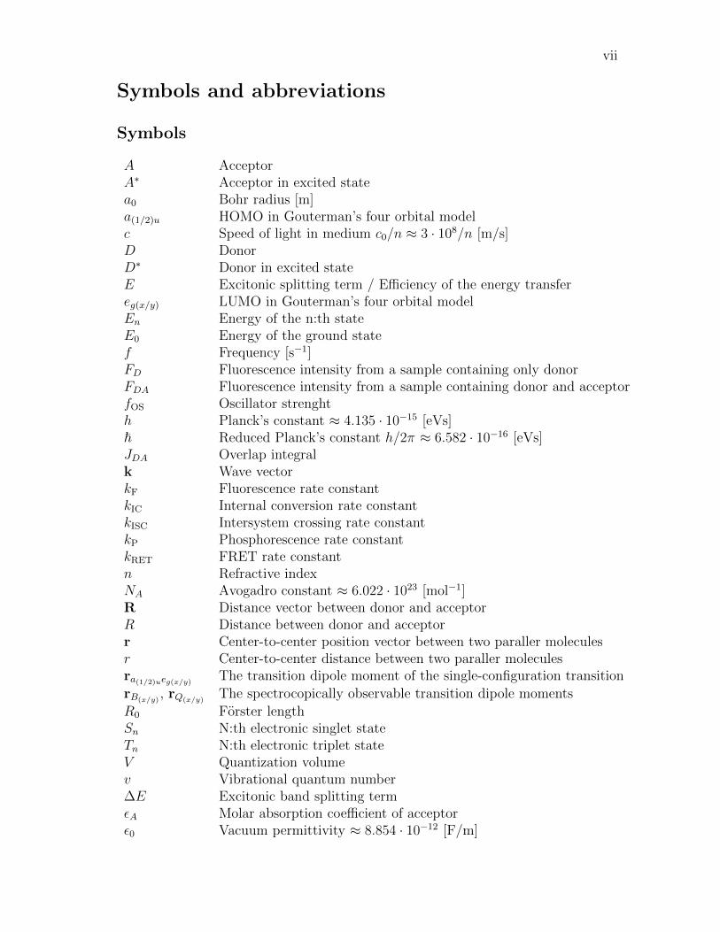
A AcceptorA∗ Acceptor in excited statea0 Bohr radius [m]a(1/2)u HOMO in Gouterman’s four orbital modelc Speed of light in medium c0/n ≈ 3 · 108/n [m/s]D DonorD∗ Donor in excited stateE Excitonic splitting term / Efficiency of the energy transfereg(x/y) LUMO in Gouterman’s four orbital modelEn Energy of the n:th stateE0 Energy of the ground statef Frequency [s−1]FD Fluorescence intensity from a sample containing only donorFDA Fluorescence intensity from a sample containing donor and acceptorfOS Oscillator strenghth Planck’s constant ≈ 4.135 · 10−15 [eVs]~ Reduced Planck’s constant h/2π ≈ 6.582 · 10−16 [eVs]JDA Overlap integralk Wave vectorkF Fluorescence rate constantkIC Internal conversion rate constantkISC Intersystem crossing rate constantkP Phosphorescence rate constantkRET FRET rate constantn Refractive indexNA Avogadro constant ≈ 6.022 · 1023 [mol−1]R Distance vector between donor and acceptorR Distance between donor and acceptorr Center-to-center position vector between two paraller moleculesr Center-to-center distance between two paraller moleculesra(1/2)ueg(x/y) The transition dipole moment of the single-configuration transition
rB(x/y), rQ(x/y)
The spectrocopically observable transition dipole moments
R0 Forster lengthSn N:th electronic singlet stateTn N:th electronic triplet stateV Quantization volumev Vibrational quantum number∆E Excitonic band splitting termεA Molar absorption coefficient of acceptorε0 Vacuum permittivity ≈ 8.854 · 10−12 [F/m]
viii
θ Inclination angle between two paraller transition dipole momentsλ Wavelength [m]λ Reduced wavelength λ/2π [m]κ Forster orientation factorµ Transition dipole moment vectorπ Ground state of the π-orbitalπ∗ Excited state of the π-orbitalσ Absorption cross-sectionτB Bulk recombination lifetimeτeff Effective lifetime of the minority carriersτF Surface recombination lifetimeτS Effective lifetime of the minority carriersΦa(1/2)ueg(x/y) Single-configuration excitations in Gouterman’s four orbital model
φD Quantum yield of donorφF Fluorescence quantum yieldΨB(x/y), ΨQ(x/y) Spectrocopically observable excited states
Operators
ak,λ Annihilation operatorHbath Bath Hamiltonian
a†k,λ Creation operator
µ Electric dipole operator / Dipole moment operator
d⊥ Displacement operatorH Hamiltonian operatorHint Hamiltonian operator for the Coulumb interactionHrad Hamiltonian operator for the quantized radiation fieldHmol Molecular Hamiltonian operatorek,λ Polarization operator
ix
Abbreviations
Abs AbsorptionATP Adenosine triphosphateBChl BacteriochlorophyllBIBO Bismuth tribonateCa CalciumCar CarotenoidChl ChlorophyllCWPL Continuous-wave photoluminescence spectroscopyCI Configuration interactionDCM DichloromethaneDFB Distributed feedbackDSC Dye-sensitized solar cellFarn FarnesylF FluorescenceFRET Forster / Fluorescent resonant energy transferGaAs Gallium arsenideHOMO Highest occupied molecular orbitalIC Internal conversionISC Intersystem crossingIUPAC International union of pure and applied chemistryLED Light-emitting diodeLi LithiumLUMO Lowest unoccupied molecular orbitalK PotassiumMS Mass spectrometryNa SodiumNd:YVO4 Neodymium:Yttrium vanadateNIR Near-infraredNR Non-radiativeNMR Nuclear magnetic resonanceMg MagnesiumPS PhotosystemPDT Photodynamic therapyPMMA Poly(methyl methacrylate)Pyro a Zn-methyl-pyro-pheophorbide aP4VP Poly(4-vinylpyridine)OH-Pyro a Zn-31-OH-methyl-pyro-pheophorbide aOLED Organic light-Emitting diodePheo PheophorbidePhy PhytylP PhosphorescencePL Photoluminescence

x
RC Reaction centerRET Resonance energy transferROS Reactive oxygen speciesTHF TetrahydrofuranTRPL Time resolved photoluminesce spectroscopyQD Quantum dotQED Quantum electrodynamicsQW Quantum wellSNOM Scanning near-field optical microscopeSTM Scannning tunneling microscopeUv-Vis Ultraviolet-visibleVR Vibrational relaxationXPS Photoelectron spectroscopyZn Zinc

1
1 Introduction
“Man cannot give a true reason for the grass under his feet why it should begreen rather than red or any other color.”
Sir Walter RaleighHistory of the world: Preface (1614)
The study of chlorophylls has attracted the attention of many bright scientists inthe past. In 1844, F. Verdeil was the first person to suggest a relationship be-tween green chlorophyll and red blood pigment, haem, which was known to containiron. Shortly after this in 1880, Felix Hoppe-Seyler gave additional proof to thishypothesis by showing spectral resemblances between hematoporphyrin and an aciddegration product of chlorophyll. After the work of Verdeil and Hoppe-Seyler, itwas suggested that chlorophylls also contained iron. However, this erroneous beliefwas corrected by Richard Willstatter in 1913, who identified chlorophylls as waterinsoluble magnesium compound with ester groups of methyl and phytyl alcohol. In1915, Richard Willstatter received a Nobel prize in chemistry “for his researches onplant pigments, especially chlorophyll”. The final steps in the structural elucidationsof chlorophyll molecules culminated in the work of Hans Fischer who showed that fortwo hydrogen atoms red would be green and only two more hydrogen atoms wouldhave ensured blood to be blue. In 1930, Hans Fischer also received a Nobel prizein chemistry “for his researches into the constitution of haemin and chlorophyll andespecially for his synthesis of haemin”.
The structural similarity of heme (iron-porphyrin) and chlorophyll (Mg-phytochlorin)is not a coincidence. Through the evolutionary process, plants have utilized chloro-phyll molecules in converting and storing the Sun’s solar energy into chemical energy.Also for many organisms, the means by which oxygen is transported, stored, reducedand activated are mediated by the heme proteins. [1] Consequently, porphyrins andchlorins are the central molecules on this planet to which all lifeforms directly relyon.
Photosynthetic process is one of the vital processes that sustains life on earth. Theprocess transforms carbon dioxide (CO2) to sugars with the help of energy from theSun. Organisms on earth that are capable of performing photosynthesis are plants,algae and some bacteria. [2] Sunlight on earth’s surface has it’s intensity maximumaround the visible wavelengths (380-750 nm) of the electromagnetic spectrum. Alsoa significant contribution of radiation exists in the near infrared area (750-1000nm) [3, 4]. To utilize this usable spectral band, the photosynthesizing organismshave developed a wide range of different light absorbing pigments. These pigmentsin plants are chlorophylls (Chl), carotenoids and bacteriochlorophylls (BChl) inbacteria. Naturally, earth contains a diverse collection of different chromophoresand the aforementioned pigments cover only a small part from the total amount.
Chlorophyll molecules are the most sensitive and efficient light-capturing pigmentsfound from nature. They perform the three important functions in photosyntheticprocess. First, they act as light-harvesting antennas that harvest light extremely
2
efficiently. Secondly, they transfer the excitation energy to the reaction center (RC)with high quantum efficiency via resonance energy transfer (RET), which is goingto be discussed in more detail in Chapter 4. Third, they participate in the chargeseparation across photosynthetic membrane in the reaction center. [2]
In plants Chl molecules have a strong absorption in blue and yellow wavelengths,hence giving the green colour for the plant. Because of this distinct feature, themolecules have inherited their name from Greek words (chloros “green”) and (phyllos“leaf”). However, bacteriochlorophylls (BChl) have a different colour than Chl,because they partially hydrogenated pyrrole rings that shift absorption to the nearinfrared region. Typically, plants and algae have two different chlorophyll moleculesparticipating in the photosynthetic process; Chl a and Chl b. Chl a is found in thereaction centers and core antennas. On the other hand, Chl b is only found in outerantennas. Since Chl b has different absorption maxima from Chl a, it broadens theavailable spectral bandwidth for photosynthesis.
One of the promising applications that bears a striking similarity with the photo-synthetic process is the Gratzel solar cell also called Dye-sensitized solar cell (DSC),which was published in Nature 1991 [5]. The inventors of DSC are Professor MichaelGratzel and Brian O’Regan. This invention also brought Prof. Gratzel the Mille-nium prize in 2010. The similarities of DSC with the plants lies in the manner,which the energy is created and also in the fact that both are able to create energyeven without direct sunlight in cloudy conditions.
In addition to photosynthetic process and chlorophylls, another interesting aspect,which is not directly related to this thesis, but necessary concerning the future workwith this subject lies in the realm of semiconductors. Quantum heterostructures(QHS) are artificially created semiconductor structures, which include QuantumWells (QW), Quantum Wires and Quantum Dots (QD). The small size of thesestructures gives rise to quantum confinement leading to the formation of discreteenergy levels that the charge carries can populate. More specifically, the quantumconfinement decreases the density of states in these structures. Therefore, thesestructures behave more like atoms or molecules, but can still have a size much largercompared to atomic dimensions. QHS are especially important for optoelectronicdevices, where they are used in the fabrication of short wavelength light-emittingdiodes (LED), diode laser and high-efficiency solar cells. [6]
Devices that utilize RET and are composed of biological and inorganic semiconduc-tor quantum heterostructures have been created previously. Usually these devicesare formed of colloidal QDs instead of planar structures [7], but planar devices alsoexists [8]. Nonetheless, the research in this field is rich ranging from theoretical toapplied approaches.
The first aim of this thesis is to develop a method to passivate and functionalizea semiconductor surface, which in this case is GaAs. Passivation is critical for theperformance of the QHS device improving the long-term stability of the device andthe quantum confinement of the QHS. With a stronger quantum confinement, thethickness of the barrier layer situated between the organic layer and the QHS can

3
be decreased, which in turn increases the coupling. In addition, it provides a se-lectively sensitized surface for the chlorophyll pigments. Secondly, to monitor thecoupling and energy transfer from the organic layer to the inorganic matrix, a signalneeds to be generated. The easiest way to achieve this goal is by spectroscopic mea-surements, and hence the organic layer is optimized to fluoresce. For this purpose,the fluorescence of PMMA-Chl, P4VP-Chl complexes and pure Chl aggregates arecompared with each other to find the optimal configuration. The samples are spincoated on a glass substrates and characterized by different spectroscopic methods,e.g., UV-Vis absorption, continous wave and time-resolved photoluminescence andfluorescence spectoscopy.
The structure of the thesis is following: Chapter 2 provides the basic aspects relatedto excitation dynamics of molecules that are required later on this thesis. Chapter 3is devoted for the properties of different chlorophyll molecules. The most importantcontent lies in the optical properties and the aggregation of chlorophylls. Chapter 4presents the principles needed to undestand the phenomena called Resonance EnergyTransfer (RET). Also in this chapter a unified theory of RET is presented. Chapters5 and 6 will be covering the experimental techniques and preparation of samples.Finally, the last two chapters present the results and the conclusions.
2 Light induced processes in molecules
This Chapter presents some important details and aspects involved in the interac-tions between light and molecules. Also the influences of the molecular environmentsto the excitated state dynamics of molecules will be discussed.
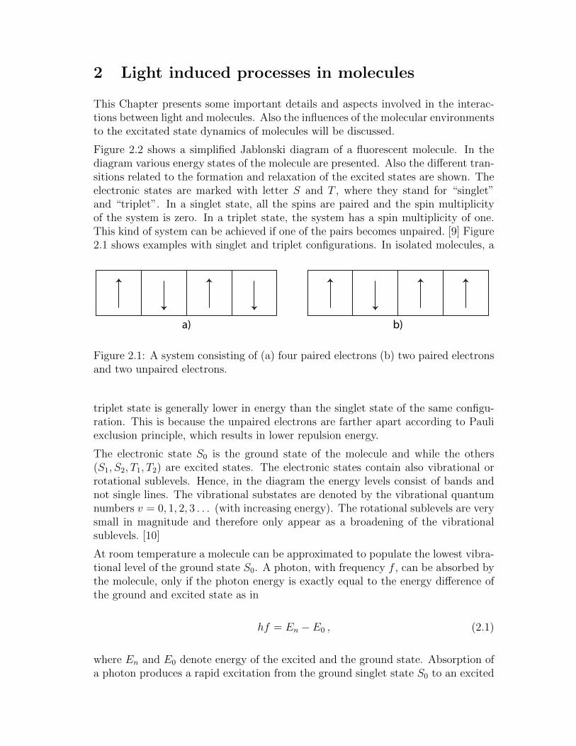
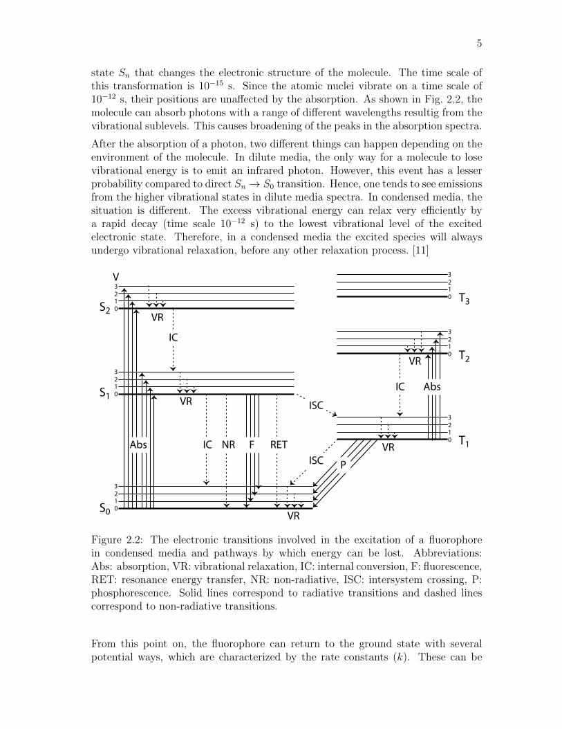
Figure 2.2 shows a simplified Jablonski diagram of a fluorescent molecule. In thediagram various energy states of the molecule are presented. Also the different tran-sitions related to the formation and relaxation of the excited states are shown. Theelectronic states are marked with letter S and T , where they stand for “singlet”and “triplet”. In a singlet state, all the spins are paired and the spin multiplicityof the system is zero. In a triplet state, the system has a spin multiplicity of one.This kind of system can be achieved if one of the pairs becomes unpaired. [9] Figure2.1 shows examples with singlet and triplet configurations. In isolated molecules, a
a) b)
Figure 2.1: A system consisting of (a) four paired electrons (b) two paired electronsand two unpaired electrons.
triplet state is generally lower in energy than the singlet state of the same configu-ration. This is because the unpaired electrons are farther apart according to Pauliexclusion principle, which results in lower repulsion energy.
The electronic state S0 is the ground state of the molecule and while the others(S1, S2, T1, T2) are excited states. The electronic states contain also vibrational orrotational sublevels. Hence, in the diagram the energy levels consist of bands andnot single lines. The vibrational substates are denoted by the vibrational quantumnumbers v = 0, 1, 2, 3 . . . (with increasing energy). The rotational sublevels are verysmall in magnitude and therefore only appear as a broadening of the vibrationalsublevels. [10]
At room temperature a molecule can be approximated to populate the lowest vibra-tional level of the ground state S0. A photon, with frequency f , can be absorbed bythe molecule, only if the photon energy is exactly equal to the energy difference ofthe ground and excited state as in
hf = En − E0 , (2.1)
where En and E0 denote energy of the excited and the ground state. Absorption ofa photon produces a rapid excitation from the ground singlet state S0 to an excited
5
state Sn that changes the electronic structure of the molecule. The time scale ofthis transformation is 10−15 s. Since the atomic nuclei vibrate on a time scale of10−12 s, their positions are unaffected by the absorption. As shown in Fig. 2.2, themolecule can absorb photons with a range of different wavelengths resultig from thevibrational sublevels. This causes broadening of the peaks in the absorption spectra.
After the absorption of a photon, two different things can happen depending on theenvironment of the molecule. In dilute media, the only way for a molecule to losevibrational energy is to emit an infrared photon. However, this event has a lesserprobability compared to direct Sn → S0 transition. Hence, one tends to see emissionsfrom the higher vibrational states in dilute media spectra. In condensed media, thesituation is different. The excess vibrational energy can relax very efficiently bya rapid decay (time scale 10−12 s) to the lowest vibrational level of the excitedelectronic state. Therefore, in a condensed media the excited species will alwaysundergo vibrational relaxation, before any other relaxation process. [11]
S0
S1
S2
T1
T2
T3
Abs FIC
IC
NR RET
V
0123
VR
VR0123
0123
0123
0123
0123
VR
VRISC
ISC
P
IC Abs
VR
Figure 2.2: The electronic transitions involved in the excitation of a fluorophorein condensed media and pathways by which energy can be lost. Abbreviations:Abs: absorption, VR: vibrational relaxation, IC: internal conversion, F: fluorescence,RET: resonance energy transfer, NR: non-radiative, ISC: intersystem crossing, P:phosphorescence. Solid lines correspond to radiative transitions and dashed linescorrespond to non-radiative transitions.
From this point on, the fluorophore can return to the ground state with severalpotential ways, which are characterized by the rate constants (k). These can be
6
divided roughly to two different distinct cases: intramolecular and intermoleculardeactivation.
The intramolecular deactivation processes include radiative and non-radiative tran-sitions. When the molecule returns from the lowest vibrational level of the excitedstate Sn to the ground state S0 by emitting a photon, it is called fluorescence (kF).When this transition occurs from the triplet state Tn to the singlet ground state S0
it is referred to as phosphorescence (kP). The lifetime of an excited singlet state isroughly 10−9 s, which also corresponds to the lifetime of the fluorescence.
Non-radiative mechanisms include internal conversion, intersystem crossing and pho-tophysical processes. Internal conversion (kIC) occurs when a vibrational states ofthe excited and ground states are coupled together and the molecule relaxes tothe ground state, while dissipating all excess energy as heat. Through intersystemcrossing (ISC) (kISC) the singlet state can be changed to the triplet manifold. Thisprocess involves a change in the spin multiplicity of the molecule. Therefore, ISCis quantum mechanically forbidded according to the selection rules for electronictransitions. This means that all transitions S0 → Tn or Tn → S0 are highly un-likely, but still possible. The probability for ISC is increased if the excited statelifetime is long and in the presence of heavy atoms. Resulting from this phosphores-cence lifetimes are also very long. [12] Finally, the excited state can be deactivatedintramolecularly by photophysical processes that include photoisomerization andphotobleaching. [9, 10]
Since immediately after the absorption the molecule undergoes vibrational relax-ation, the emitted photon will have lower energy compared to the quanta absorbed.This shifts the maxima of the fluorescence spectrum to longer wavelengths relativeto the absorption maxima. This phenomenon is termed as the Stokes shift. Themaximum of the phosphorescence spectrum is located at even higher wavelengths,since phosphorescence originates from the non-vibronically excited T1 state, whichlower in energy than the excited S1 state.
Intermolecular deactivation pathways include energy transfer to another moleculeand quenching. The quenching can happen by molecular collision or by forminga complex. The long-range interaction between molecules is termed as Forstermechanism (kRET), which is discussed more in Chapter 4 and the short-range in-teraction energy transfer termed as Dexter mechanism (kDEX). Dexter mechanismrequires a wavefunction overlap and therefore can only occur at distances of order10− 20 A. [13]
Each of the these processes can occur in parallel, and measuring the rate constantsof one process can be used to determine the rate constants of other processes.

7
3 The chlorophylls
This section is divided in to four major parts. Section starts by introducing somebasic properties of various chlorophyll (Chl) molecules and their natural occurrency.The next section contains some of the basic chemical and structural properties ofChls. Third part introduces the optical properties of chlorophylls, e.g., absorptionand emission. Since the optical properties arise from the intrinsic electronic structureof the molecules, the most popular physical models used in the description of theconjugated π-electron system are presented, concentrating especially in the four-orbital model. Last part is devoted to the examination of aggregation properties ofChl complexes. Special attention is given to the optical properties of Chl aggregates.
3.1 Natural occurrence and basic properties
The most abundant colouring pigments found in nature comprise from differentpyrrole pigments (porphyrins, (bacterio)chlorohylls, haem, vitamin B12, bile pig-ments) [14]. Chlorophylls and bacteriochlorophylls are the photosynthetic pigmentsthat can be found only from plants, bacteria and algae. Chls are all chlorins with theexception of Chl c, which is a phytoporphyrin type. The different Chl c’s are pho-tosynthetic pigments found from marine lifeforms. The most abundant Chls foundin nature are Chl a and Chl b, which usually occur in ratio of 3:1 [2]. These twochromophores are the major photosynthetic pigments in the plant kingdom. Nearly100 different Chls and BChls are known today. Majority of these pigments existin anoxygenic bacteria [15]. The term ‘anoxygenic’ is used for bacteria that do notproduce oxygen in the photosynthetic process. Bacteria that belong to this groupare purple bacteria, green sulphur bacteria and heliobacteria.
A second very important pigment found in photosynthetic organisms is the carotenoidmolecule. Carotenoids absorb light ranging from blue to orange and also take partin light-harvesting. In addition, another important function of carotenoid moleculesis in removing harmful triplets created by the long-lived excited states of Chl andBChl molecules. These triplet states are very lethal to living organisms, since theyreact with available oxygen and produce singlet oxygen, which is a very strong freeradical. Interfering with this mechanism is the basis of many herbicides. This formof oxygen is called reactive oxygen species (ROS). [2]
Because of this Chls offer a tempting possibility in photodynamic therapy (PDT).PDT is used in the therapy of cancer to kill cancer cells. The strong absorp-tion of Chls at long wavelengths is particularly beneficial, since at the wavelengths650 - 850 nm the light penetration into living tissue is maximixed. Unfortunatelymost natural Chl molecules are water-insoluble and very unstable in the presenceof light. However, chemically modified Chl molecules usually show better stabilityand tunability for the needs of PDT. Hence Chl derivates are used as sensitizersin photodynamic therapy. Chl derivatives can also be applied as natural biocidesutilizing the same principles as used in PDT. [16]

8
Chemically, Chls are unstable in the presence both acids and bases. Also oxida-tion and light can degrade the Chl molecules. They have a significant tendency foraggregation and interaction with their molecular environments. Their optical prop-erties are characterized by long-lived excited states and intense absorption in thespectral range of 330 - 800 nm. In aggregates or in vivo this range can be extendedto 1020 nm [2].
The structure of Chl molecules and their derivates is very often investigated by X-raydiffraction [17], nuclear magnetic resonance (NMR) spectroscopy [18, 19] and massspectroscopy (MS). Especially a combination of NMR and MS is usefull in deter-mining the structural information. From the optical techniques, UV-Vis absorptiongives qualitative information about aggregation degree of the samples and also iden-tification of the chromophores. Photoluminescence measurements can be used toprobe the electronical structure of chromophores. Circular dichroism spectroscopycan yield additional information about the stereochemistry of Chls in solutions andaggregates.
3.2 Structure
Chlorophylls belong to the family of molecules called porphyrins. Porphyrin moleculesare aromatic heterocyclic macrocycles composed of four pyrrole molecules connectedtogether with methine bridges (−−CH−). Figure 3.1a-b shows the pyrrole and por-phine molecules. Porphine molecule is rarely met in this form, but it functions as asimplified model, e.g., in ab initio calculations of molecular orbitals.
NH
a)
NH HN
N N
c)
NH HN
N N
d)b)
NH HN
N N
NH HN
N N
O OH O OH
e)
Figure 3.1: (a) Pyrrole. (b) Porphine. (c) Chlorin. (d) Bacteriochlorin. (e) Proto-porphyrin IX.
In porphyrins, when the double bond between C-17 and C-18 is saturated, i.e., thedouble bond is reduced to a single bond, chlorin macrocycle is formed. Here theletter C stands for asymmetric carbon and the numbering is performed accordingto Fig. 3.2. Furthermore, the saturation of the bond between C-7 and C-8 forms

9
N N
NN
R7
R8
R12
R3
O
O OR17
R132α
A B
CD
E
MR20
R132β
Phytyl (Phy)
Farnesyl (Farn)
H
H
N N
NN
R3
O
O OR17
A B
CD
EH
H
H
R8β
R8α
M
R132αR132β
Phytochlorin type Bacteriophytochlorin type
1
2
34
5
6
7
8
9
10
1112
13
14
21 22
131132
2324
15
1617
18
19
20
1
2
34
5
67
8
9
10
1112
13
14
21 22
131132
2324
15
1617
18
19
20
1
23
4
5
67
8
9
1011
13
1415
12 16
Figure 3.2: Molecule on the left shows a phytochlorin type of molecule and on theright side is the bacteriophytochlorin. On the bottom of the figure two of the mostcommon “tails” are shown connecting to the position R17. The structural variantsof different chlorohyll molecules are presented in Table 3.1. Numbering accordingto IUPAC-UIB nomenclature (1988).
the bacteriochlorin macrocycle. Chlorin and bacterichlorin macrocycles are shown inFig. 3.1c and d. These three different macrocycles form the basis of the variety of thechlorophyll molecules found in the nature. Figure 3.1e shows a protoporphyrin IXmolecule that is very close to another important organic molecule haem, responsiblefor the oxygen binding properties of blood and also its distinctive red colour. Asthe prefix “proto” implies, protoporhyrin IX is also the prototype form, from whichthe variety of different (B)Chl molecules are formed. Furthermore, the IUPAC-IUBnomenclature in Fig. 3.2 emphasizes the fact that the isocyclic ring E in phytochlorinand bacteriophytochlorin types is derived from the C-13 propionic acid side chainof protoporphyrin IX.
Chlorophylls are chlorin derivates, where a fifth isocyclic pyrrole molecule is fusedinto the porphine structure. This additional pyrrole molecule gives the prefix “phyto”for porphyrin and chlorin type of molecules. Hence they are called phytoporphyrinand phytochlorin. For example, Chl c has phytoporhyrin macrocycle and Chl a andChl b have a phytochlorin macrocycle. Occasionally, phytochlorin is referred to asphorbin by some authors, but this name will not be used in this thesis. Chls gen-erally have Mg as the central metal and sesqui- (C15) or di-terpenoid (C20) alcoholesterified to the C-17 propionic acid chain, but there exist exceptions to both ofthese characteristics. For example, Pheophytin a, which is involved in the electron
10
transfer in the type II reaction centers, does not have the central metal. In otheraspects, Pheo a is exactly like Chl a.
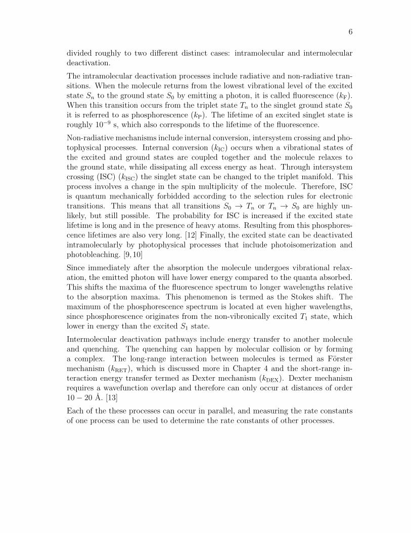
Table 3.1: Various peripheral substituents of chlorophyll and bacteriochlorophyllmolecules corresponding to Fig. 3.2. Data taken from [2].
Pigment R3 R7 R8 ( R8α/8β)a R12 R132α/132β R17 R20 M
Chl a C2H3 CH3 C2H5 CH3 COOCH3/H Phy H MgChl b C2H3 CHO C2H5 CH3 COOCH3/H Phy H MgChl c1
b - CH3 C2H5 - - H H MgChl d CHO CH3 C2H5 CH3 COOCH3/H Phy H MgPheo ac C2H3 CH3 C2H5 CH3 COOCH3/H Phy H H2
BChl ad COCH3 - H/C2H5 - COOCH3/H Phy - MgBChl b COCH3 - -/−−CH−CH3 - COOCH3/H Phy - MgBChl c CHOHCH3 CH3 CH2CHn(CH3)3−n
e CH3/C2H5
d
H/H Farn CH3 Mg
BChl f CHOHCH3 CHO CH2CHn(CH3)3−nd CH3/
C2H5e
H/H Farn H Mg
a Phytochlorin type has only R8-coordination, but bacteriochlorin type has two differentbranches emerging from R8 denoted as α and β.
b Chl c has a phytoporphyrin macrocycle. Chl c are also called as chlorophyllides (Chlides),where the “-ide” ending denotes an unesterified acid side chain at C-17.
c Pheo a stands for Pheophytin a. It has the same structure as Chl a, but is missing thecentral metal.
d BChl stands for bacteriochlorophyll.e Complex mixture of pigments with varying substituents at C8 and C12.
Phytochlorins contain four asymmetric (chiral) centers, which are located in C-132,C-17, C-18 and in the central metal. The phytol chain contains two asymmetriccenters in C-7 and C-11 (notice different numbering in phytyl tail and phytochlorinmacrocycle), which results in six asymmetric centers in phytochlorins containingphytyl chains. Bacteriophytochlorins have additional asymmetric centers in C-7and C-8, hence giving it eight chiral centers with phytyl tails. [20]
3.2.1 The macrocycle and the electronic structure
The large macrocycle is the basis for both optical and redox chemistry of Chls.The electronic structure in porphyrins and (bacterio)chlorins is based on a planarmacrocycle of 20 carbon atoms surrounding a central core of four nitrogen atoms.This configuration supports highly stable conjugated π-orbital electronic structure,which has alternating single and double bonds between the carbon atoms. The pla-narity of the macrocycle ensures a maximum overlap between the adjacent π-orbitals.Therefore, the π-electrons are free to move to neighboring π-orbital resulting in thedelocalization of the π-electrons around the whole macrocycle.

11
The planarity of the macrocycle and the delocalization of π-electrons are the twoclassical criteria found in organic chemistry for aromacity. Consequently, since por-phyrin and (bacterio)chlorin macrocycles are aromatic they naturally follow Huckel’srule. Huckel’s rule state that aromatic molecule must have 4n+2 π-electrons, wheren is zero or an integer. When placed in to external magnetic field, these delocalizedπ-electrons induce global ring currents that circulate around the whole macrocycle.In porphine, there exists many different bifurcations in the circulation of the ringcurrents since the pyrrole subunits remain unsaturated. However, in chlorins andbacteriochlorins the pyrrole subunits are saturated, which in turn limits the possiblepathways for the ring currents. Figure 3.3a shows the tradional 18π-[18]annulenearomatic pathway for a porphine macrocycle. This delocalization pathway can alsobe applied in chlorins and bacteriochlorins [21]. However, recent studies suggest thatin reality all the π-electrons in the macrocycle participate in the aromatic delocal-ization, and the total delocalization pathway is a linear combination of all possible(4n+ 2) pathways [22].
N NH
NNH
N NH
NNH
NN
NN
NHNH
NHNH
y
xa) b)
Figure 3.3: A porphine macrocycle showing (a) the the traditional 18π-[18]annulenedelocalization pathway in porphyrins and chlorins (b) the diagonal arrows as thetwo orthogonal symmetry axes denoted as x and y.
Many quantum mechanical models from a simple quantum wire model to moredetailed models exist to explain the electronic properties of porphyrins and (bac-terio)chlorins. However, the first model to give a satisfactory picture of the opti-cal properties of porphyrins and chlorins was the four-orbital model developed byGouterman [23, 24]. In addition, the four-orbital model has provided the basis forthe theoretical work concerning the electronic and spectroscopic properties of theporphyrin molecules. [2]. In spite of the problems in Gouterman’s model accordingto the newest research [25, 26], it still provides a reasonably realistic picture of theoscillator strengths and transition energies. In Gouterman’s four-orbital model onlythe two highest occupied molecular orbitals (HOMO-1, HOMO) and two lowest un-occupied molecular orbitals (LUMO and LUMO+1 ) are considered. As an example,these orbitals are shown shown in Fig. 3.4 for a porphine macrocycle. The HOMOs

12
c1(egx) c2(egy)
b1(a2u) b2(a1u)
Figure 3.4: The HOMOs (b1 and b2) and LUMOs (c1 and c2) of a porphine macro-cycle used in the Gouterman’s four-orbital model. Solid and dashed circles indicatethe sign. Symmetry nodes drawn in heavy lines. Picture taken from [27].
are labeled as b1, b2 and LUMOs c1,c2 to allow them to be followed into systemswith less than D4h symmetry. Furthermore, the two LUMOs are divided from eachother by using the two orthogonal symmetry axes defined in Fig. 3.3b and denotedas egx and egy.
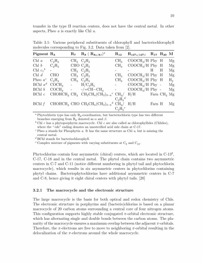
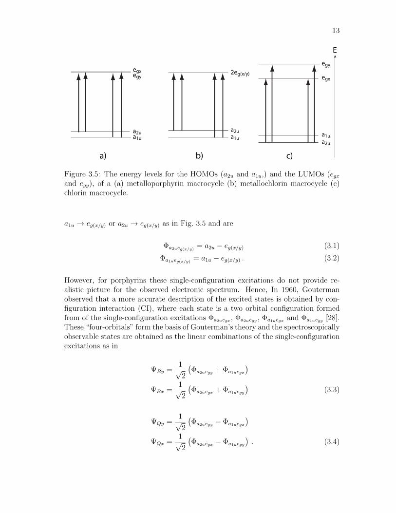
The structure of the macrocycle contribute substantially to the degeneracy andthe energy of the orbitals. For example, a free-base porphine has D2h symmetryaccording to the Schonflies notation and the LUMO levels are almost degenerate.The introduction of a metal in the porphine macrocycle increases the symmetryand hence metalloporphyrin macrocycle has D4h symmetry. Resulting from thisthe LUMOs are exactly degenerate, but a1u is shifted to lower energy. However inchlorins, the saturation one of the pyrrole subunits reduces the symmetry of themolecule and chlorin macrocycles have C2v symmetry. This causes the LUMO andHOMO energy levels to spread apart.
Figure 3.5 shows the energy levels for the two HOMOs and LUMOs for a (a) free-baseporphine, (b) metalloporphyrin and (c) chlorin macrocycle respectively. The arrowsin Fig. 3.5 represent all the allowed electric-dipole transitions between the HOMOand the LUMO [2, 28]. In molecular theory, the electronic spectrum is interpretedin terms of single-electron transitions from occupied to unoccupied orbitals. Thusaccording to Fig. 3.5, the single-configuration excitations are described by transitions
13
a2ua1u
2eg(x/y)
b)a)
E
c)
a2u
a1u
egy
egx
a2ua1u
egyegx
Figure 3.5: The energy levels for the HOMOs (a2u and a1u,) and the LUMOs (egxand egy), of a (a) metalloporphyrin macrocycle (b) metallochlorin macrocycle (c)chlorin macrocycle.
a1u → eg(x/y) or a2u → eg(x/y) as in Fig. 3.5 and are
Φa2ueg(x/y) = a2u − eg(x/y) (3.1)
Φa1ueg(x/y) = a1u − eg(x/y) . (3.2)
However, for porphyrins these single-configuration excitations do not provide re-alistic picture for the observed electronic spectrum. Hence, In 1960, Goutermanobserved that a more accurate description of the excited states is obtained by con-figuration interaction (CI), where each state is a two orbital configuration formedfrom of the single-configuration excitations Φa2uegx , Φa2uegy , Φa1uegx and Φa1uegy [28].These “four-orbitals” form the basis of Gouterman’s theory and the spectroscopicallyobservable states are obtained as the linear combinations of the single-configurationexcitations as in
ΨBy =1√2
(Φa2uegy + Φa1uegx
)ΨBx =
1√2
(Φa2uegx + Φa1uegy
)(3.3)
ΨQy =1√2
(Φa2uegy − Φa1uegx
)ΨQx =
1√2
(Φa2uegx − Φa1uegy
). (3.4)
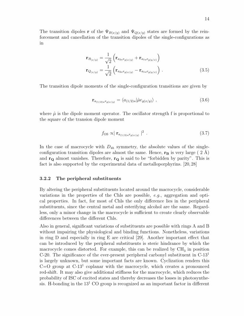
14
The transition dipoles r of the ΨB(x/y) and ΨQ(x/y) states are formed by the rein-forcement and cancellation of the transition dipoles of the single-configurations asin
rB(x/y)=
1√2
(ra2ueg(x/y) + ra1ueg(y/x)
)rQ(x/y)
=1√2
(ra2ueg(x/y) − ra1ueg(y/x)
). (3.5)
The transition dipole moments of the single-configuration transitions are given by
ra(1/2)ueg(x/y) = 〈a(1/2)u|µeg(x/y)〉 , (3.6)
where µ is the dipole moment operator. The oscillator strength f is proportional tothe square of the transion dipole moment
fOS ∝| ra(1/2)ueg(x/y) |2 . (3.7)
In the case of macrocycle with D4h symmetry, the absolute values of the single-configuration transition dipoles are almost the same. Hence, rB is very large ( 2 A)and rQ almost vanishes. Therefore, rQ is said to be “forbidden by parity”. This isfact is also supported by the experimental data of metalloporphyrins. [20,28]
3.2.2 The peripheral substituents
By altering the peripheral substituents located around the macrocycle, considerablevariations in the properties of the Chls are possible, e.g., aggregation and opti-cal properties. In fact, for most of Chls the only difference lies in the peripheralsubstituents, since the central metal and esterifying alcohol are the same. Regard-less, only a minor change in the macrocycle is sufficient to create clearly observabledifferences between the different Chls.
Also in general, significant variations of substituents are possible with rings A and Bwithout impairing the physiological and binding functions. Nonetheless, variationsin ring D and especially in ring E are critical [29]. Another important effect thatcan be introduced by the peripheral substituents is steric hindrance by which themacrocycle comes distorted. For example, this can be realized by CH3 in positionC-20. The significance of the ever-present peripheral carbonyl substituent in C-131
is largely unknown, but some important facts are known. Cyclization renders thisC−−O group at C-131 coplanar with the macrocycle, which creates a pronouncedred-shift. It may also give additional stiffness for the macrocycle, which reduces theprobability of ISC of excited states and thereby decreases the losses in photosynthe-sis. H-bonding in the 131 CO group is recognized as an important factor in different
15
interaction with proteins. [2]
3.2.3 The central metal
The most important aspect of chlorophyll type of molecules is their metal-bindingability [14]. It has decisive influence on the excited state kinetics, and this in turnaffects how they perform in the photosynthetic process. Through the evolutionaryprocess, nature has selected Mg as the central metal. This maximizes the excitedstate lifetime, while still maintaining low intersystem crossing to the triplet state.Transition metals with open d-shells and heavy metals would exhibit a large inter-system crossing probability, hence they would not function properly. Other metalslike K, Na, Li and Ca can form unstable complexes, while trivalent metals intro-duce an extra charge. Thus, the only possible metals that remain are Mg++, Zn++
and 2H+, and in fact they are the only possible central metals found in nature. [2].The most common bound metals that are found in nature are magnesium and iron,which gives additional selectional advantage for Mg. Other reason why Mg is pre-ferred over Zn in photosynthetic systems could originate from the lower mass of Mg,which in turn lowers the probability for radionless relaxation by ISC. However, inother aspects Zn-Chls seem to be very similar to Mg-Chls, and Zn-Chls can replaceMg-Chls in all complexes [30,31].
3.2.4 The esterifying alcohol
The esterifying alcohol is located in C-17 as shown in Fig. 3.2. For most (B)Chlsthis is phytyl or farnesyl, but other alcohols also exist. Phytyl and farnesyl chainsare presented in Fig. 3.2. Of all the structural features, least is known about thefunctional significance of this long-chain esterifying alcohol. The influence of alco-hol in the electronic structure of the molecule is negligible, since the macrocycleand central metal are mainly responsible for the properties [25]. In mono-dispersesolutions, it has a very minor effect in the absorption properties.
Nevertheless, the alcohol moiety has a considerable effect in the interactions be-tween the Chl molecules and its environment including the apo-protein, other Chls,carotenoids and lipids. For example, since the phytyl chain is hydrophobic it makesChl a (and other Chls containing phytyl-chain) water insoluble. It is also notewor-thy to mention that the alcohol chain has a considerable influence in the aggregationproperties of Chls, especially in micellar systems [32]. Alcohol is also an importantpacking factor determining the spacing and orientation of Chls with respect to eachother. This is a remarkably important aspect in photosynthetic systems where thedistance and orientation between chromophores influence the efficiency of the en-ergy transfer. All available structures determined by X-ray diffraction measurementssupport the spacing function created by the alcohol moiety [33].
16
3.3 Optical properties
Conjugated molecules usually exhibit strong absorption in the wavelength range of220-1500 nm [10] and Chls are not exceptions in this sense. The absorption spectrum
400 500 600 700Wavelength (nm)
Abs
orba
nce
(rel
ativ
e)
QyQy
BxBy
Bx,y
By
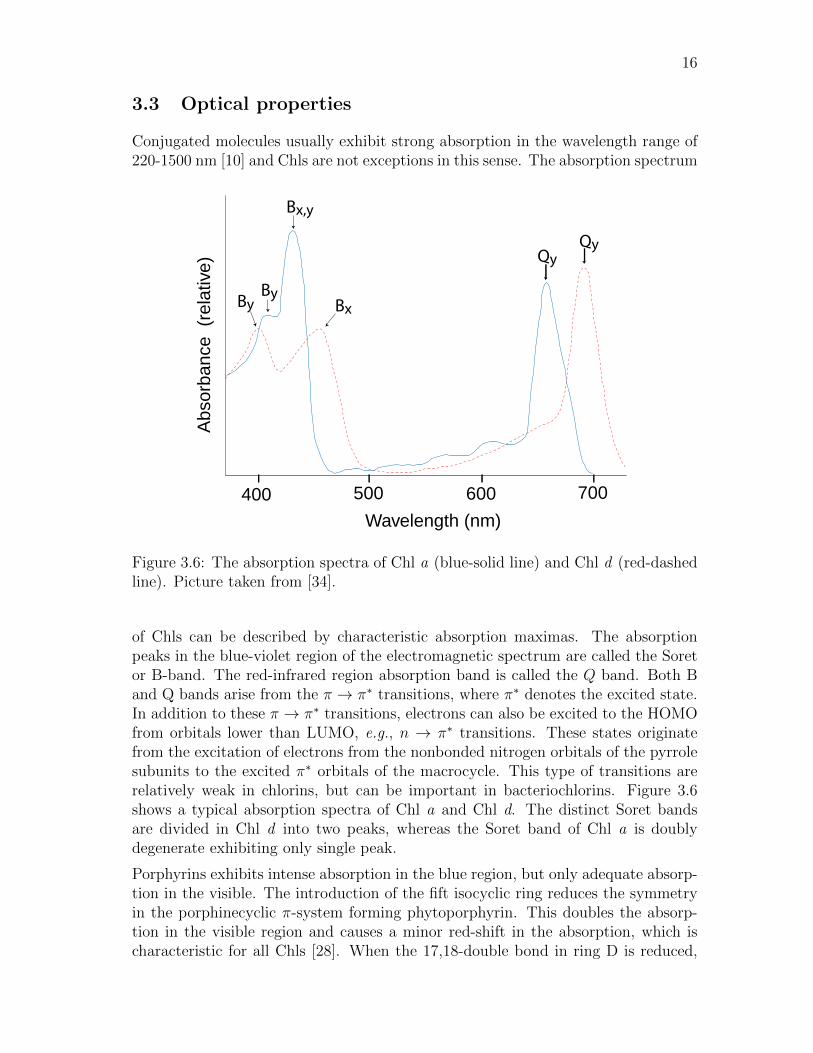
Figure 3.6: The absorption spectra of Chl a (blue-solid line) and Chl d (red-dashedline). Picture taken from [34].
of Chls can be described by characteristic absorption maximas. The absorptionpeaks in the blue-violet region of the electromagnetic spectrum are called the Soretor B-band. The red-infrared region absorption band is called the Q band. Both Band Q bands arise from the π → π∗ transitions, where π∗ denotes the excited state.In addition to these π → π∗ transitions, electrons can also be excited to the HOMOfrom orbitals lower than LUMO, e.g., n → π∗ transitions. These states originatefrom the excitation of electrons from the nonbonded nitrogen orbitals of the pyrrolesubunits to the excited π∗ orbitals of the macrocycle. This type of transitions arerelatively weak in chlorins, but can be important in bacteriochlorins. Figure 3.6shows a typical absorption spectra of Chl a and Chl d. The distinct Soret bandsare divided in Chl d into two peaks, whereas the Soret band of Chl a is doublydegenerate exhibiting only single peak.
Porphyrins exhibits intense absorption in the blue region, but only adequate absorp-tion in the visible. The introduction of the fift isocyclic ring reduces the symmetryin the porphinecyclic π-system forming phytoporphyrin. This doubles the absorp-tion in the visible region and causes a minor red-shift in the absorption, which ischaracteristic for all Chls [28]. When the 17,18-double bond in ring D is reduced,
17
blue light
red light
IC
FluorescenceRET IC
ISCTripletState
S2
S1
S0
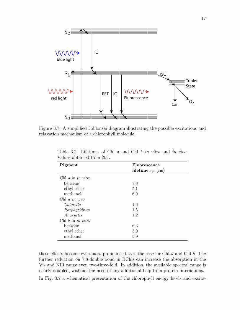
CarO2
Figure 3.7: A simplified Jablonski diagram illustrating the possible excitations andrelaxation mechanism of a chlorophyll molecule.
Table 3.2: Lifetimes of Chl a and Chl b in vitro and in vivo.Values obtained from [35].
Pigment Fluorescencelifetime τF (ns)
Chl a in in vitrobenzene 7,8ethyl ether 5,1methanol 6,9
Chl a in vivoChlorella 1,6Porphyridium 1,5Anacystis 1,2
Chl b in in vitrobenzene 6,3ethyl ether 3,9methanol 5,9
these effects become even more pronounced as is the case for Chl a and Chl b. Thefurther reduction on 7,8-double bond in BChls can increase the absorption in theVis and NIR range even two-three-fold. In addition, the available spectral range isnearly doubled, without the need of any additional help from protein interactions.
In Fig. 3.7 a schematical presentation of the chlorophyll energy levels and excita-

18
tion and relaxation dynamics is shown.The Figure shows that only two dominantexcitation wavelengths exist corresponding to the Soret (S0 → S2) and Q (S0 → S1)absorption bands. Once the electron is excited from the ground state S0 either to thefirst S1 or the second S2 energy level, a part of the energy can be released by VR tothe lowest vibrational level within the excited state or by IC to a lower energy state.From the first energy level S1 electron has many possible pathways to the groundstate, which are IC, fluorescence, FRET to another molecule or a triplet state viaISC. This triplet state produces reactive oxygen species or may be deactivated bya carotenoid molecule. Also only the transition between the levels S1-S0 can beused in photosynthesis. The reason for this is that the charge transfer performedby the photosystem can be realized only at wavelengths 680 nm (PSII) or 700 nm(PSI) [36].
Table 3.3: Absorption and fluorescence spectra maximas of photosyntheticpigments in different solvents. Values obtained from [2].
Pigment Absorptionin situ
Absorptionin solutionλmax(ε)[solvent]a
Emissionin solutionλmax[solvent]
Chl a ∼440, 670-720 430, 662(78.8)[A] 668[A]430, 662(90)[D] 666[D]
Chl b ∼460, 630-680 457, 646(46.6)[A] 652[A]454, 644(56.3)[D] 646[D]
Chl d ∼440, ∼690 447, 668(98.3)[D] 695[D]454, 644(56.3)[D] 646[D]
Pheo a ∼680 408, 505, 534, 667(55.2)[D] 673[D]
BChl a ∼440,∼690, 800 357, 391, 573, 772(91)[D] 800-960 365, 608, 772(60)[M]
BChl b <400,∼600, 800 368, 408, 579, 794(106)[D] 810-1020 368, 407, 582, 795[A]
BChl c ∼460, 730-760 432, 622, 660(92.7)[D] 667[D]435, 620, 670(70.9)[M]
a λmax in nm, ε in cm−1mM−1, solvent abbreaviations: A = acetone, D =diethylether and M= methanol.
According the Fig. 3.7, the fluorescence quantum yield can be expressed using therate constants as [37]
φF =kF
kF + kIC + kISC + kRET
, (3.8)
where kF is the probability for spontaneous emission S1 → S0, kIC is the probablityfor non-radiative transition S1 → S0, kISC is the probability for transition S1 → T1
and kRET is the probability for energy transfer to another molecule. For example,
19
when two molecules are brought close to each other, kRET and kISC are increased,which in turn decreases φF according to Eq. 3.8.
Hence, the optical properties of (B)Chls are exceptionally sensitive to the molecularenvironments [38]. In Table 3.2 the lifetimes of Chl a and Chl b in vivo and in vitroare listed. As can be seen from the values, the lifetimes are order of nanosecond evenin vivo. These long lifetimes of the excited singlet state give rise to a high probabilityfor ISC. Therefore, singlet to triplet transitions and ROS pose a problem when usingChls. In addition, the smaller fluorescence lifetimes in vivo is a clear indication ofan efficient energy transfer between the Chl molecules (Eq. 3.8) [39]. Table 3.3demonstrates the differences in the absorption and fluorescence spectra in differentmolecular envinroments. Even more pronounced variations can be induced by adirect protein-pigment or pigment-pigment interactions [40].
3.4 Aggregation
In nature, Chls are found in both aggregated forms and in protein-pigments com-plexes. In protein-pigment complexes, the protein matrix acts as the supportingstructure for the Chls. It also ensures an optimal distance and orientation betweenthe chromophores, since dense packing of chromophores has a danger called con-centration quenching. This phenomena can be understood as a statistical process.There is always a chance that the pigment molecule is defective in such a way thatthe excited state of the molecule is short lived and relaxes by rapid internal con-version into ground state. If this defective molecule is isolated, then this process isnegligible. But when this molecule is coupled to other molecules, they can act as asink, which degrades the excitations of the light-harvesting unit to heat [20].
However, again, an exception can be found from the green photosynthetic bacteria,which grow in low light intensity envinroments. The light-harvesting organelle ofthese bacterias, called “chlorosome”, is most efficient natural antenna system formedby the self-assembly of BChls. It has developed to increase the light absorption perunit volume and to decrease the amount of protein per chromophore thus savingresources for the bacteria [41]. Similar kind of tubular structures have been syn-thetically fabricated in vitro by simply utilizing the self-assembling properties ofBChls [42].
Resulting from their molecular architecture, Chls can very easily function as a build-ing blocks for supramolecular interactions. These interactions have a non-covalentnature and the strongest of interactions is the metal ligation. For a long time it wasknown that Mg binds the extra ligands so strongly that it is practically never fourcoordinate. Removal of the extra ligand in unpolar solvents gives rise to increasedaggregation where another Chl is donating a ligand. The central metal is also in-volved in the interactions between Chls and their apo-proteins [28]. In the crystalstructures formed by Chl molecules, a variety of ligands have been identified: in morethan 50% of known binding sites the ligand is histidine, but glutamine, asparagine,C−−O groups and even water are known to be ligated [33,43]. These interactions may

20
be considered very important in the self-organized assembly of Chl molecules espe-cially in hydrophobic environments. Ligand interactions are also known to changethe electron density of the macrocycle and hence the properties of the molecule [44].
Second strongest bonding in the hierarchy of the supramolecular interactions is thehydrogen bonding. In the presence of multiple of hydrogen bonds, a very strongand directional bonding can be induced. Also nearly all (B)Chls carry a carbonylgroup (C−−O) in the C-131 and C-132 position, which can act as acceptor group forthe hydrogen bonding.
Figure 3.8: Stack of paraller oriented Chls with the phytyl tail replaced by a methylgroup. The 31-OH group can ligate with the central metal (M) and function asa hydrogen bond donor. The carboxyl group may function as a hydrogen bondacceptor.
The aromatic macrocycle is also an important reason for the pronounced tendencyof aggregation of Chls via π-π interactions also referred to as π-π-stacking. π-π-interactions arise from the intermolecular overlapping of the π-orbitals in thearomatic moieties. This type of bonding is strong and π-π interactions play asubstantial role in the interactions between Chls and proteins in photosyntheticcomplexes [20,45].
Since all of these interaction mechanisms are simultaneouslya ctive, the stabilizedsupramolecular assembly can be much more stable in comparison with individualnon-covalent interactions [46]. Figure 3.8 shows one possible set of Chl-Chl aggre-gation when the chromophores are aligned paraller to each other.
Chlorophyll aggregates usually show diminished fluorescence and shortening of theexcited state lifetimes compared to monomeric moieties. [20] The decrease in fluo-rescence can be explained with efficient energy transfer between the molecules andwith concentration quenching, but a more thorough inspection requires the help ofexcitonic theory of molecular crystals developed by Davydov in 1946. [47] Accordingto the theory, the aggregation also increases the probability for ISC and thus en-hances the lowest triplet state excitation in certain cases. [48] Generally, the degree

21
Monomerlevels
Head-to-tail
e’
e’’
Paraller
g
e
g0 90(deg)
Dimerlevels
r
∆E
Figure 3.9: A schematic presentation of a exciton energy band for a dimer or identicalmolecules with paraller transition dipoles. The dashed line with the red crossescorresponds to the forbidden out-of-phase dipole arrangement. Adapter from [48].
of aggregation is observed from the spectral shifts in the absorption spectra. Thesespectral shifts can be qualitively explained by the exciton model applied for molec-ular spectroscopy introduced by Kasha et al [48]. In this approach, the Coulumbicinteractions between the closely-packed chromohopres induce excitonic splitting ofthe excites states with different transition energies and oscillator strenghts. For ex-ample, a dimer with paraller transition dipole moments the excitonic splitting termin the point-dipole point-dipole approximation is given by
E =µu · µv
r3− 3
(µu · r) (µv · r)r5
, (3.9)
where µu/v is the transition dipole moment of the molecule u/v and r is center-to-center position vector between the molecules, when u is placed in the origin. Whenthe dimer composes of identical chromophores the use of Eq. 3.9 yields the excitonicband splitting term:
∆E =2 | µge |2
r3
(1− 3 cos2 θ
), (3.10)
where θ is the inclination angle between the molecules. This situation is illustratedin Fig. 3.9, where the effect of the excitonic interaction to the dimer energy levels ispresented. The orientation of the chromophore dipole moments determines whetherthe excitonic coupling results in a higher (H-type) or lower (J-type) transition energy
22
compared to monomeric moeities. Also, Fig. 3.9 shows that the transition betweenthe H-aggregate and the J-aggregate takes place at an angle θ = 54.7. At this anglethe band splitting is zero no matter what the separation between the chromophoresmight be.
Furthermore, the difference in the optical behaviour of H-type and J-type aggre-gates is not limited to absorption spectra. For example, H-aggregates exhibit fluo-rescence quenching [48], which can be disadvantageous for optical systems, whereasJ-aggregates may show even improved fluorescence compared to monomeric species.[49] Nevertheless, above models are only good approximations, since the aggregatesare bound to exist in many different forms (dimers, trimers, oligomers) and orienta-tions. Hence, the spectral shifts can be only used to detect the onset of aggregation,but do not allow for a quantitative inspection of the molecular structure.

23
4 Resonance energy transfer
Fluorescence or Forster resonance energy transfer (FRET, RET) is a process, whereenergy is transferred between atoms or molecules over distances that are longer thanatomic (or moleculer) radii. In the near field that ranges from less than 10 A to 100A, the transfer is radiationless and characterized by the inverse sixth-power depence.In the far field the transfer is radiative and is characterized by the inverse squarelaw.
In 1920 it was known that fluorescence polarization started to decrease from solu-tions, when the concentration of fluorophores reached a critical value. Jean Perrinwas the first to explain this effect by a Coulomb dipole-dipole interaction between themolecules [50]. This theory helped to undestand how the energy could be transferredto another molecule across some gap, even when there was not any wavefunctionoverlap between the molecules. However, Perrin made an error in his calculations,by assuming sharp resonances absortion and emission spectra. It took some yearsbefore Theodor Forster formulated the correct results taking into account the broad-ening of the spectra [51,52]. He also derived the current form of the theory and alsoverified it by experimental data. [53]
RET is a widely used technique in medical, biological and physical sciences. Us-ing RET, researchers have created colloidal QDs for chemical sensors [7, 54, 55], insitu monitoring of proteins in a living cell [56] and molecular rules for biologicalapplications [57]. Artificial reaction centers have been created using cascading QDstructures, where the funnel-like band gap profiles guide the exciton efficiently tothe lowest band gap QD [58].
In section 4.1 the basic principles about RET are explained. Section 4.2 deals aboutthe unified theory of RET, which can be derived using quantum electrodynamics(QED), which connects both the near- and far field regimes. Section 4.3 deals withorientational aspects between chromophores that affect the effiency of the RET.
4.1 Basic considerations
Resonance energy transfer requires two probes, a fluorescent donor (D) and anacceptor (A), which does not need to be fluorescent. When the donor is irradiatedwith appropriate energy, this creates an oscillating dipole, which can resonate withthe acceptor in the near field. This resonating dipole-dipole interaction negotiatesthe energy from the donor to the acceptor. These interacting chromophores aretreated as point dipoles, but more accurate models also exist. [59] The elementrayRET process can be summarized with the following reaction formula
D∗ + A→ D + A∗ , (4.1)
where the donor, which was initially in an excited state D∗, undergoes a transitionto the electronic ground state, while the acceptor is promoted from its ground state

24
to an excited state A∗.
For an effective energy transfer to occur in the near field some requirements have tobe fulfilled. First, the fluorescence spectrum of D and the absorbtion spectrum ofA should adequately overlap. Also the quantum yield of donor (φD) and the molarabsorption coefficient of acceptor (εA ≥ 1000) have to be large enough. Thirdly, thetransition dipole vector have to be favorably oriented to each other. [59,60]
The most common formulae found in literature associated with RET are the ef-ficiency of the energy transfer and rate constant (kRET). These formulae can bederived using classical approach with the Coulombic multipolar expansion, but withthis approach they only apply in the near field. [61–63]
The efficiency of the energy transfer is a measure how much energy is transferredfrom D to A. It is essentially a quantum yield of the energy transfer, which isdefined as
E =The number of quanta transferred from D to A
The number of quanta absorbed by D. (4.2)
E can be measured in many ways including steady-state or time-resolved methods.However, the most popular method is the use of steady-state measurements andmeasuring the fluorescence intensity from a sample containing only D (FD) andfluorescence intensity of A from a sample containing both D and A. Using thefluorescent intensities Eq. 4.2 can be defined as
E = 1− FDAFD
. (4.3)
If the values FD and FA are normalized to their respective concentration of D, Eq. 4.3can also be expressed as [59]
E =1
1 + (R/R0)6. (4.4)
where R0 is the Forster length, which relates to the donor-acceptor distance whenthe efficiency given by Eq. 4.4 is 50 %. Forster length can also be defined as
R60 =
9000 ln(10)
128π5NA
κ2n−4φDJDA , (4.5)
where NA ≈ 6, 022·1023 mol−1 is the Avogadro constant, κ2 is the Forster orientationfactor, φD is the quantum efficiency of D, n is refractive index of the material (whichis usually assumed isotropic and non-dispersive) and JDA is the overlap of the Dfluorescence spectrum with the A absorption spectrum. The Forster orientation

25
factor is defined as [59]
κ = ~nA · ~nD − 3(~nR · ~nD)(~nR · ~nR) , (4.6)
where ~nD,A = µD,A/ | µD,A | are the corresponding unit vectors of the acceptor anddonor transition dipole moments and ~nD is the unit vector pointing from donor toacceptor. The effect of κ will be discussed in more detail in Chapter 4.3.
The overlap integral is defined as
JDA =
∞∫0
FD(λ)εA(λ)λ4 dλ/
∞∫0
FD(λ)dω (M−1cm3) , (4.7)
where FD(ω) is the donor fluorescence per unit wavelength interval and εA(λ) is theacceptor molar absorption coefficient at waveleght λ. Usually the donor fluorescenceis normalized to unity, which simplifies the overlap integral to
JDA =
∞∫0
FD(λ)εA(λ)λ4 dλ (M−1cm3) . (4.8)
The constant in the Eq. 4.5 depends on the used units. For example, the acceptorabsorption spectrum can be expressed with the molar absorption coefficient ε or asthe absorption cross-section σ, which are connected by
σ = 1000 ln(10)ε
NA
(M−1cm2) . (4.9)
In Fig. 4.1, a plot of RET efficiency (E) is presented as a function of distance R.The efficiency has been calculated with Eq. 4.4. The different R0 values are takenfrom Ref. [64]. From the graph one can see that when the distance is ≤ 0.5R0 thecurve becomes flat. Also the maximum efficiency in this relationship is reached moreabruptly than its minimum. Because of this, longer distances may be determinedslightly more accurately than shorter distances.
The second commonly used formula is the rate of the energy transfer, which is givenby
kRET =1
τD
(R0
R
)6
. (4.10)
26
0 20 40 60 80 1000
0.2
0.4
0.6
0.8
1
Distance between donor and acceptor (Å)
Ener
gy tr
ansf
er e
ffic
ienc
y
D=ANT-AMP (nucleotide), A=Tb(III) (Ca Site), R0 = 5 ÅD=DCI (Lys), A=DDPM (Cys), R0 = 21.9 ÅD=e-ADP (nucleotide), A=TNP-ADP (nucleotide), R0 = 51 Å
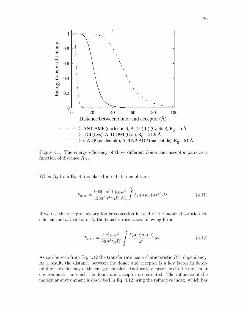
Figure 4.1: The energy efficiency of three different donor and acceptor pairs as afunction of distance RDA.
When R0 from Eq. 4.5 is placed into 4.10, one obtains
kRET =9000 ln(10)φDκ
2
128π5n4τDR6NA
∞∫0
FD(λ)εA(λ)λ4 dλ . (4.11)
If we use the acceptor absorption cross-section instead of the molar absorption co-efficient and ω instead of λ, the transfer rate takes following form
kRET =9c4φDκ
2
8πn4τDR6
∞∫0
FD(ω)σA(ω)
ω4dω . (4.12)
As can be seen from Eq. 4.12 the transfer rate has a characteristic R−6 dependency.As a result, the distance between the donor and acceptor is a key factor in deter-mining the efficiency of the energy transfer. Another key factor lies in the molecularenvironments, in which the donor and acceptor are situated. The influence of themolecular environment is described in Eq. 4.12 using the refractive index, which has
27
n−4 dependency. Naturally, if other molecules are in the vicinity of donor and accep-tor, they induce losses or alternative pathways for energy transfer and thus decreasethe transfer rate between donor and acceptor. It is also noteworthy to state thatEq. 4.11 is more practical when chemical information about the fluorescent speciesis known and Eq. 4.12 is more usable when spectroscopic data is available. However,all of the variables used in both equations can be determined with relative ease usingproper equipment.
4.2 Quantum electrodynamical inspection of RET
Using the semiclassical inspection of the phenomenom does not not fully solve theproblem, since it only applies for the near field. Hence, the semiclassical theoryis only an approximation. Using Quantum Electrodynamics (QED) theory, whereboth the matter and photons are quantized, one can obtain a unified theory for theradiative and radiationless energy transfer. With this theory, the different near- andfar field behaviours are the limiting cases for a more general mechanism that operatesover all distances. In classical theories, radiationless energy transfer contains anassumption that energy is transferred instantaneously from D to A, but this isjustified only in the near zone, i.e., when the distance between the donor and theacceptor is less than the reduced wavelength λ = λ/2π, where λ is the wavelengthcorresponding to the energy transfer.
Usually the molecules that participate in the energy transfer are surrounded by othermolecules. Naturally, this affects the transfer dynamics. This formulation uses thecommon multipolar (Power-Zienau-Woolley) form of QED. The key point of thistheory is the cancellation of all longitudinal Coulumbic interactions [65]. Whenusing this formulation any interaction between electronically neutral species invokesthe creation and annihilation of photons.
To examine the energy transfer between two selected molecules D and A, the wholesystem is divided into two parts. One subsystem consists of the selected moleculepair of D and A. The other subsystem consists of quantized radiation field and theremaining molecules that are situated in the surrounding medium, which is referredto as the “polariton bath”. In this formulation the interaction between D and A ismediated by the bath polaritons.
When the system is unperturbed, it is desribed by the zeroth-order Hamiltonian(H0). The excitation of the system can be treated as a perturbation of system, whichis given by the interaction term (V ). Using these notations the total Hamiltonianis [59, 65]
H = H0 + V , (4.13)
28
where
H0 = Hbath +Hmol(D) +Hmol(A) (4.14)
V = Hint(D) +Hint(A) . (4.15)
Hbath is the “bath” Hamiltonian that contains the radiation Hamiltonian and thecontributions of all other molecules except D and A. It is given by
Hbath = Hrad +∑ξ 6=D,A
(Hmol(ξ) +Hint(ξ)) , (4.16)
where ξ denotes the molecule ξ. For the sake of simplicity, only the energy transferbetween donor-acceptor pair in vacuum will be examinded, since the mathematicaltreatment is simpler. However, the examination of the effect of dielectric mediumsurrounding the molecular pair follows the same logic as in vacuo. The only differ-ence is that the energy is not mediated by the bath polaritons, but virtual photons.The photons are deemed virtual, since at small distances between D and A their life-time is short according to the uncertainty principle. However, when the interaction-pair separation is increased this uncertainty is reduced and photons gain a realcharacter, which is characterized by the radiative transfer in the far zone. Whenexamining the transfer dynamics in vacuo, the effects of surrounding molecules arediscarded in Eq. 4.16 and the zeroth-order Hamiltonian is reduced to
H0 = Hrad +Hmol(D) +Hmol(A) + V . (4.17)
Since the interaction term V in Eq. 4.15 stays the same, the total Hamiltonian isgiven by
H = Hrad +Hmol(D) +Hmol(A) +Hint(D) +Hint(A) . (4.18)
The Hamiltonian for the quantized radiation field, which can be expressed using thecreation- and annihilation operators (a†k,λ, ak,λ) corresponding to wavevector k andpolarization state of a photon λ (λ = 1, 2) [65,66]
Hrad =∑k,λ
~ck(a†k,λak,λ1 + evac
), (4.19)
where∑k,λ
is a shorthand notation of∑k
∑λ
, ak,λ is a shorthand notation of aλ(k)
and evac is the vacuum energy (usually evac = 1/2). The creation- and annihilation

29
operators obay the following relations
[ak ,λ
, a†k′ ,λ′
] = δk,k′δλ,λ′ , nk,λ = a†k,λak,λ (4.20)
a†k,λak,λ = n |nk,λ〉 , n = 0, 1, 2, . . . (4.21)
ak,λ =√n |n− 1〉 , n = 1, 2, 3, . . .
ak,λ |0〉 = 0 (4.22)
ak,λ |n〉 =√n+ 1 |n+ 1〉 , n = 0, 1, 2, . . . (4.23)
where |0〉 is the vacuum state, i.e., a state without photons.
The interaction Hamiltonian describes the interaction between the quantized radi-ation field and the molecule ξ. When the dipole-dipole coupling (E1-E1 coupling)is allowed, the electric dipole approximation of the interaction Hamiltonian is suffi-cient. The reason for this is that the higher-order electric coupling and magnetic mul-tipolar couplings are comparatively small. Nevertheless, one example when this ap-proximation is not valid can be found in plants. Coupling between two chromophoresin plants, carotenoid and chlorophyll molecules, is not E1-E1 allowed. In such caseshigher-order multipole coupling have to be taken into consideration. [67, 68] Againfor simplicity, processes are assumed to be E1-E1 allowed, and within this approxi-mation the electric dipole interaction Hamiltonian is
Hint = −ε−10 µ(ξ) · d⊥(Rξ) , (4.24)
where d⊥(Rξ) is the electric displacement operator of molecule ξ positioned at placeRξ and µ is the electric dipole operator of molecule ξ. Displacement operator canbe written as the mode expansion [65]
d⊥(R) = i∑k,λ
(~ckε02V
)(ek,λak,λe
ik·R − e−k,λa†k,λe
−ik·R), (4.25)
where the sum has been taken over radiation modes characterized by the wave-vectork and polarization λ, e k,λ is the polarization vector, e−k,λ is the complex conjugate ofthe polarization vector, V is an arbitrary quantization volume and R is the positionof the molecule.
With the help of Eq. 4.1, the transfer process can be split into initial and final states,which consists of three state vectors: donor, acceptor and the radiation field. Theinitial state of the system is described by the state vector |I〉. In the initial state, the

30
donor is excited and the acceptor is in the ground state. The final state is describedby the state vector |F 〉 D being in the ground state and A excited. Radiationfield is in both cases in the ground state, since the virtual photon that mediatesenergy exists only between these states. Hence the radiation field is described bythe vacuum state |0〉. State vectors of donor and acceptor are assumed to implicitlycontain the vibrational contributions, which are separable from the electronic stateson the basis of the Born-Oppenheimer principle as
|D〉 = |Del〉 |ϕ(n)D 〉 , |D∗〉 = |D∗el〉 |ϕ
(r)D∗〉 (4.26)
|A〉 = |Ael〉 |ϕ(m)A 〉 , |A∗〉 = |A∗el〉 |ϕ
(p)A∗〉 , (4.27)
where subscript “el” refers to the electronic part of the state vectors, indices n, r,m and p specifying the vibrational, rotational or other sublevels of D or A.
The initial (|I〉) and final (|F 〉) states of the whole system (molecules plus radiation)can be presented as the product wavefuntion
|I〉 = |D∗〉 |A〉 |0〉 , |F 〉 = |D〉 |A∗〉 |0〉 , (4.28)
with corresponding energies
EI = eD∗ + eA + evac, EF = eD + eA∗ + evac . (4.29)
Since the energy transferred has to satisfy the energy convervation, i.e., initial andfinal states have to have the same energy, the total energy transferred in the processis EI = EF = ~cK. In the presence of a surrounding medium, this would notnecessarily be the case, since the presence of other molecules could induce losses.
The energy transfer is a second-order process, where the energy is mediated by thevirtual photons as discussed before. This process is presented in Fig. 4.2. Accordingto Fig. 4.2, two intermediate states are possible in the energy transfer. Figure 4.2acorresponds to the situation (q = 1), where the transition D∗ → D precedes thetransition A → A∗, when in the the second case (q = 2) the order is opposite,as in Fig. 4.2b. The latter process presents a rather anomalous situation, wherethe transition A → A∗ produces a virtual photon and the annilation of the photoninduces a downward transition of D. Nevertheless, both processes must be taken intoaccount when using the time-dependent perturbation theory. First order processesare the absorption of a photon and the emission of a photon, which are shown inFig. 4.3. First order prosesses can be described with first order perturbation theory,but they do not contribute to the transfer process and can be neglected. The rateof the transfer of excitation energy from the donor to the acceptor is given by the

31
D* A
D A*
k, λ
D* A
D A*
k, λ
a) b)
Figure 4.2: Time-ordered Feynman diagrams for the resonant energy transfer, wheretime is progressing upward. In both cases a virtual photon labeled k, λ transfersenergy from the initially excited donor D∗ to the acceptor A.
a) b) A
A*
D*
D
Figure 4.3: Time-ordered Feynman diagrams for a) photoabsorption and b) photoe-mission. Again time progressing upwards.
Fermi’s Golden Rule [66]
ΓFI =2π
ρ~ | 〈F |V |I〉 |2 δ(EI − EF ) , (4.30)

32
where ρ is the density of final states. The matrix element 〈F |V |I〉 can be definedusing second order perturbation theory as follows [69,70]
〈F |V |I〉 =2∑q=1
〈F |V |Mq〉 〈Mq|V |I〉EI − Eq
=〈F |Hint |M1〉 〈M1|Hint |I〉
eD∗ − eD︸ ︷︷ ︸~cK
−~ck+〈F |Hint |M2〉 〈M2|Hint |I〉
eA − eA∗︸ ︷︷ ︸−~cK
−~ck, (4.31)
where M1 and M2 correspond to intermediate states, in which either both donorand acceptor are in ground (q = 1) or excited (q = 2) state. In both states a virtualphoton with energy ~ck exists. The energies corresponding to these states are givenby
E1 = eD + eA + ~ck, E2 = eD∗ + eA∗ + ~ck (4.32)
and the state vectors|M1〉 = |D〉 |A〉 |1〉 (4.33)
and|M2〉 = |D∗〉 |A∗〉 |1〉 , (4.34)
where|1〉 = a†k,λ |0〉 , (4.35)
is the radiation field promoted to one photon state.Since solving of the matrix elements defined in Eq. 4.30 requires some extensivecalculations, the derivation is presented in Appendix A. The result is
〈F |V |I〉 = µfulli (D)Vij(K,R)µfull
j (A) , (4.36)
where Vij is the retarded dipole-dipole coupling tensor between the donor and ac-ceptor. In the presence of other molecules, the only difference would be in Vij, butotherwise the derivation would be the same.
Vij(K,R) =K3eiKR
4πε0
[(δij − 3~Ri
~Rj
)( 1
K3R3− i
K2R2
)− (δij − ~Ri
~Rj)1
KR
],
(4.37)
where ~R = R/R. The above electromagnetic tensor contains the R−3 term charac-teristic for the near zone, R−1 for the far zone and also R−2 term for the intermediatedistances between near and far zone. Notice that the orientational factors of nearand far field are different leading to range dependence in fluorescence anisotropy.
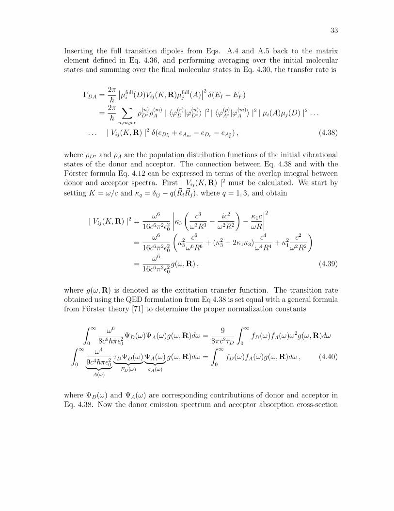
33
Inserting the full transition dipoles from Eqs. A.4 and A.5 back to the matrixelement defined in Eq. 4.36, and performing averaging over the initial molecularstates and summing over the final molecular states in Eq. 4.30, the transfer rate is
ΓDA =2π
~∣∣µfulli (D)Vij(K,R)µfull
j (A)∣∣2 δ(EI − EF )
=2π
~∑n,m,p,r
ρ(n)D∗ρ
(m)A | 〈ϕ(r)
D |ϕ(n)D∗〉 |
2 | 〈ϕ(p)A∗ |ϕ
(m)A 〉 |
2 | µi(A)µj(D) |2 . . .
. . . | Vij(K,R) |2 δ(eD∗n + eAm − eDr − eA∗p) , (4.38)
where ρD∗ and ρA are the population distribution functions of the initial vibrationalstates of the donor and acceptor. The connection between Eq. 4.38 and with theForster formula Eq. 4.12 can be expressed in terms of the overlap integral betweendonor and acceptor spectra. First | Vij(K,R) |2 must be calculated. We start by
setting K = ω/c and κq = δij − q(~Ri~Rj), where q = 1, 3, and obtain
| Vij(K,R) |2 =ω6
16c6π2ε20
∣∣∣∣κ3
(c3
ω3R3− ic2
ω2R2
)− κ1c
ωR
∣∣∣∣2=
ω6
16c6π2ε20
(κ2
3
c6
ω6R6+ (κ2
3 − 2κ1κ3)c4
ω4R4+ κ2
1
c2
ω2R2
)=
ω6
16c6π2ε20g(ω,R) , (4.39)
where g(ω,R) is denoted as the excitation transfer function. The transition rateobtained using the QED formulation from Eq 4.38 is set equal with a general formulafrom Forster theory [71] to determine the proper normalization constants
∫ ∞0
ω6
8c6~πε20ΨD(ω)ΨA(ω)g(ω,R)dω =
9
8πc2τD
∫ ∞0
fD(ω)fA(ω)ω2g(ω,R)dω∫ ∞0
ω4
9c4~πε20︸ ︷︷ ︸A(ω)
τDΨD(ω)︸ ︷︷ ︸FD(ω)
ΨA(ω)︸ ︷︷ ︸σA(ω)
g(ω,R)dω =
∫ ∞0
fD(ω)fA(ω)g(ω,R)dω , (4.40)
where ΨD(ω) and ΨA(ω) are corresponding contributions of donor and acceptor inEq. 4.38. Now the donor emission spectrum and acceptor absorption cross-section

34
can be defined as
σA(ω) =ω2µ2
A
3ε0c2√π~
∑m,p
ρ(m)A | 〈ϕ(p)
A∗ |ϕ(m)A 〉 |
2 δ(eAM− eA∗p + ~ω) (4.41)
FD(ω) =ω2µ2
D
3ε0c2√π~
∑n,r
ρ(m)D | 〈ϕ(r)
D |ϕ(n)D∗〉 |
2 δ(eD∗n − eDr − ~ω) . (4.42)
The entities 〈ϕ(p)A∗ |ϕ
(m)A 〉 and 〈ϕ(r)
D |ϕ(n)D∗〉 can be identified as the Frank-Condon factors
of the acceptor and donor respectively. With the defined variables, the transfer rateis
ΓDA =9
8πc2τD
∞∫0
FD(ω)σA(ω)ω2g(ω,R)dω . (4.43)
If we examine the energy transfer in the near zone (KR 1), the excitation transferfunction in Eq. 4.39 becomes
g(ω,R) =
(κ2
3
c6
ω6R6+ (κ2
3 − 2κ1κ3)c4
ω4R4+ κ2
1
c2
ω2R2
)≈ κ2
3
c6
ω6R6, (4.44)
and Eq. 4.43 is reduced to
ΓDA =9c4κ2
3
8πτDR6
∞∫0
FD(ω)σA(ω)
ω4dω . (4.45)
This is exactly the same equation as Eq. 4.12, which was obtained by the classicaltreatment in vacuum, i.e, n ≈ 1. In the far field (KR 1) the excitation transferfunction in Eq. 4.39 becomes
g(ω,R) ≈ κ21
c2
ω2R2, (4.46)
and Eq. 4.43 is reduced to
ΓDA =9κ2
1
8πτDR2
∞∫0
FD(ω)σA(ω)dω . (4.47)

35
With the help of QED a unified theory of energy transfer can be developed. Theresults given by QED prove that the radiationless and the radiative processes arebased exactly on the same physical process. The only difference between these pro-cesses lies in the interaction distance between the donor and acceptor. Furthermore,different interaction distances are enough to yield totally different orientational be-haviour in near and farfield.
Another interesting phenomenon associated in the resonance energy transfer is calledthe surface energy transfer (SET), in which either the donor or acceptor is a surface,e.g., a quantum well. In this case the donor-to-acceptor separation distance has ainverse 4th power dependence, hence enabling much longer interaction distancesbetween the donor and acceptor. [57]
Altogether, resonance energy transfer is a crucial intermolecular excitation transfermechanism in biological and synthetic systems. For example, it plays a substantialrole as a conduction mechanism in conductive polymers, which are used to fabricateorganic light emitting diodes (OLED) or polymer solar cells. [10]
4.3 Orientational aspects
As found out in the previous sections, the energy transfer depends also from theorientational factor κ, which is dependent on three variables. These variables weredefined previously in the Forster orientation factor from Eq. 4.6 as
κ = ~nA · ~nD − 3(~nR · ~nD)(~nR · ~nR) ,
where ~nD is the unit vector along the emission transition moment of the donor, ~nAis the unit vector along the absorption transition moment of the acceptor and ~nr isthe unit vector along a line, which is a line drawn from the centers of D to A. Thisis further illustrated in Fig. 4.4.
As seen in the Section 4.2, the orientational factors are different in the near, interme-diate and far zones. This leads to a completely different fluorescence depolarizationbehaviour in these three cases. For the Forster energy transfer, the transfer dependsonly weakly on the average mutual orientation of the donor and acceptor. This is thereason for the considerable reduction (1/25) of fluorescence anisotrophy followingthe energy transfer in isotropic or randomly oriented systems. Photon reabsorptionis even seven times greater in the raditionless case, when compared to the raditiativetransfer. Instead in the far zone, the energy transfer between molecules with paralleltransition dipoles is preferred leading to a smaller loss of polarization in a randomlyoriented system. [71]
There exists three common ways to express κ2 as a function of various angles related

36
nrnD_
_nA_
Figure 4.4: The three unit vectors ~nD, ~nA and ~nr.
to the orientation of the molecules further illustrated in Fig. 4.5:
κ2 =(
cos(θT )− 3 cos(θD) cos(θA))2
(4.48)
κ2 =(
sin(θD) sin(θA) cos(ϕ)− 2 cos(θD) cos(θA))2
(4.49)
κ2 = cos2(ω)(1 + 3 cos2(θD)
)2. (4.50)
The angle between ~nD and ~nr is θD and the same logic applies to the angle θA. θTcorresponds to the angle between ~nD and ~nA. ϕ is the angle between the projectionsof ~nD and ~nA on a plane perpendicular to ~nr. ω is the angle between ~nA and theelectric dipole field induced by the donor transition moment. These vectors andtheir angles are further illustrated in Fig. 4.5. The highest value that κ2 can attain
nD_
θD
DR-PLANE DR-PLANE DR-PLANE
ϕ
DA-PLANE
DR-PLANEDR-PLANE
AR-PLANE
AR-PLANE
AR-PLANE
ωEDA-
PLANEnr_
nA_
θA
nD_ nA
_
θT θD
nA_
nD_
eD_
Figure 4.5: A figure illustrating the different polar angles and planes associated inRET. Picture modified from [59].
is 4, which occurs if both ~nD and ~nA are paraller or antiparaller to ~nr. The lowestvalue is 0, which corresponds to a situation, where ~nA is perpendicular to the electricfield produced by the donor (or vice versa). The case κ2 = 4 can only occur in a

37
few ways, but κ2 = 0 can be realized in an infinite number of ways. Straighforwardcalculation of the rotational average from the Eq. 4.50 yields the value 2/3, sincethe average value of cos2 taken from a polar angle is 1/3.
That is often the reason why κ2 is replaced by the value of 2/3 in scientific stud-ies, but this is justified only when the chromophores are spherical, or behave likea sphere because they rapidly diffuse through all possible orientations. If the chro-mophores are not rapidly diffusing or diffusing through a limited set of orientations,this approximation can lead to significant errors. [72]
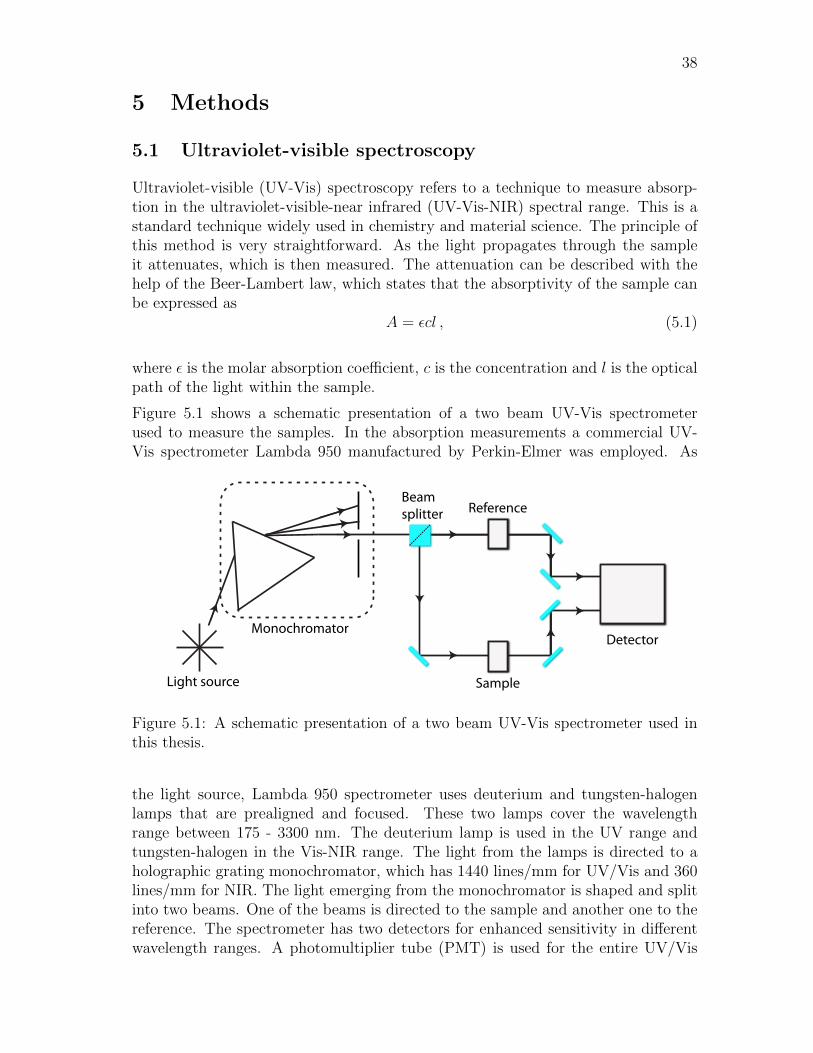
38
5 Methods
5.1 Ultraviolet-visible spectroscopy
Ultraviolet-visible (UV-Vis) spectroscopy refers to a technique to measure absorp-tion in the ultraviolet-visible-near infrared (UV-Vis-NIR) spectral range. This is astandard technique widely used in chemistry and material science. The principle ofthis method is very straightforward. As the light propagates through the sampleit attenuates, which is then measured. The attenuation can be described with thehelp of the Beer-Lambert law, which states that the absorptivity of the sample canbe expressed as
A = εcl , (5.1)
where ε is the molar absorption coefficient, c is the concentration and l is the opticalpath of the light within the sample.
Figure 5.1 shows a schematic presentation of a two beam UV-Vis spectrometerused to measure the samples. In the absorption measurements a commercial UV-Vis spectrometer Lambda 950 manufactured by Perkin-Elmer was employed. As
Monochromator
Beamsplitter
Detector
Light source
Reference
Sample
Figure 5.1: A schematic presentation of a two beam UV-Vis spectrometer used inthis thesis.
the light source, Lambda 950 spectrometer uses deuterium and tungsten-halogenlamps that are prealigned and focused. These two lamps cover the wavelengthrange between 175 - 3300 nm. The deuterium lamp is used in the UV range andtungsten-halogen in the Vis-NIR range. The light from the lamps is directed to aholographic grating monochromator, which has 1440 lines/mm for UV/Vis and 360lines/mm for NIR. The light emerging from the monochromator is shaped and splitinto two beams. One of the beams is directed to the sample and another one to thereference. The spectrometer has two detectors for enhanced sensitivity in differentwavelength ranges. A photomultiplier tube (PMT) is used for the entire UV/Vis
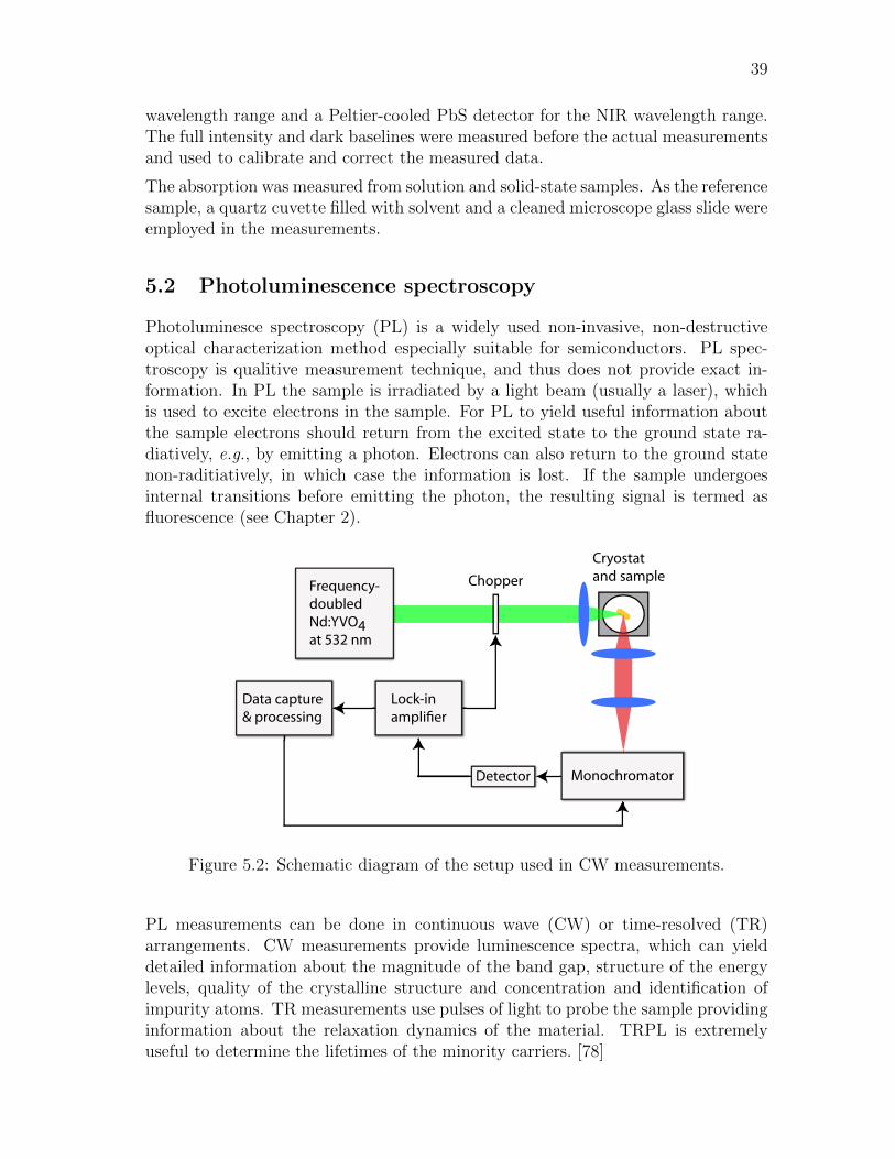
39
wavelength range and a Peltier-cooled PbS detector for the NIR wavelength range.The full intensity and dark baselines were measured before the actual measurementsand used to calibrate and correct the measured data.
The absorption was measured from solution and solid-state samples. As the referencesample, a quartz cuvette filled with solvent and a cleaned microscope glass slide wereemployed in the measurements.
5.2 Photoluminescence spectroscopy
Photoluminesce spectroscopy (PL) is a widely used non-invasive, non-destructiveoptical characterization method especially suitable for semiconductors. PL spec-troscopy is qualitive measurement technique, and thus does not provide exact in-formation. In PL the sample is irradiated by a light beam (usually a laser), whichis used to excite electrons in the sample. For PL to yield useful information aboutthe sample electrons should return from the excited state to the ground state ra-diatively, e.g., by emitting a photon. Electrons can also return to the ground statenon-raditiatively, in which case the information is lost. If the sample undergoesinternal transitions before emitting the photon, the resulting signal is termed asfluorescence (see Chapter 2).
Frequency-doubled Nd:YVO4 at 532 nm
Cryostatand sample
Detector Monochromator
Data capture & processing
Lock-in amplier
Chopper
Figure 5.2: Schematic diagram of the setup used in CW measurements.
PL measurements can be done in continuous wave (CW) or time-resolved (TR)arrangements. CW measurements provide luminescence spectra, which can yielddetailed information about the magnitude of the band gap, structure of the energylevels, quality of the crystalline structure and concentration and identification ofimpurity atoms. TR measurements use pulses of light to probe the sample providinginformation about the relaxation dynamics of the material. TRPL is extremelyuseful to determine the lifetimes of the minority carriers. [78]
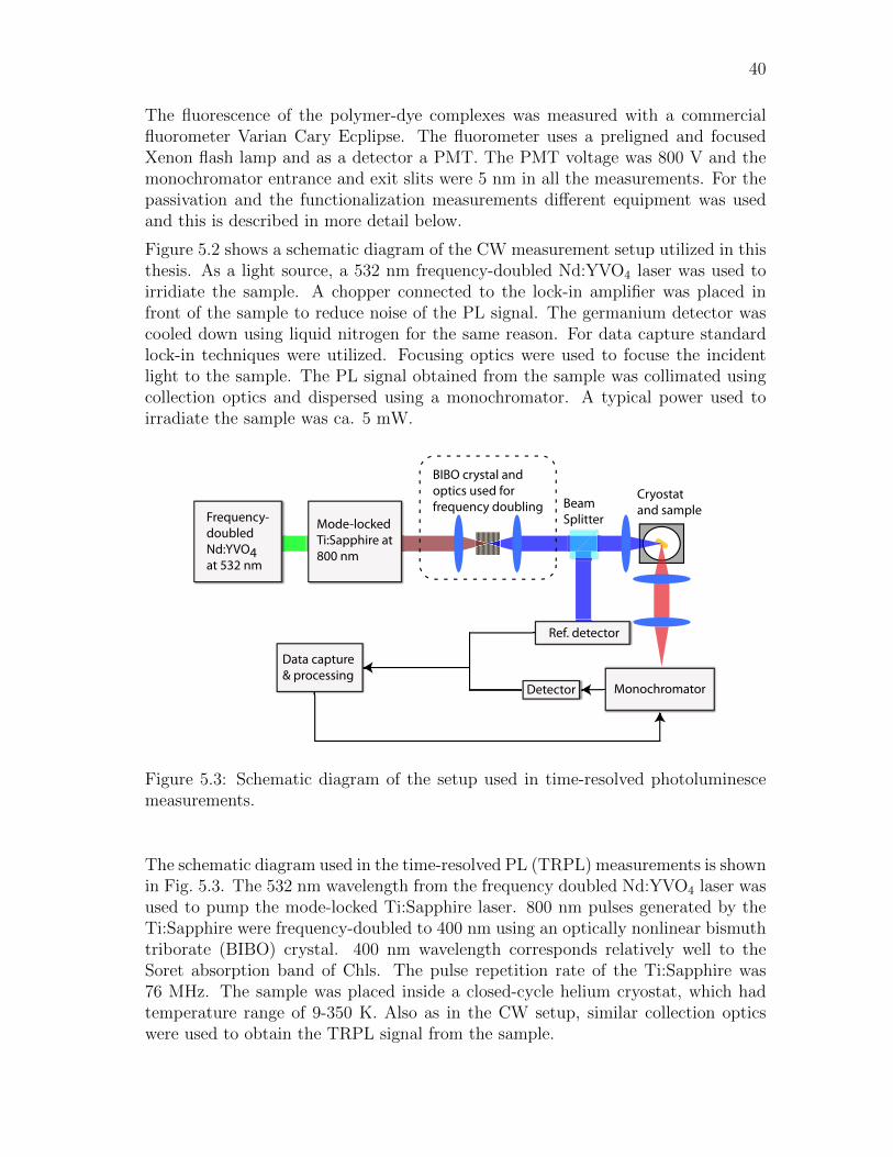
40
The fluorescence of the polymer-dye complexes was measured with a commercialfluorometer Varian Cary Ecplipse. The fluorometer uses a preligned and focusedXenon flash lamp and as a detector a PMT. The PMT voltage was 800 V and themonochromator entrance and exit slits were 5 nm in all the measurements. For thepassivation and the functionalization measurements different equipment was usedand this is described in more detail below.
Figure 5.2 shows a schematic diagram of the CW measurement setup utilized in thisthesis. As a light source, a 532 nm frequency-doubled Nd:YVO4 laser was used toirridiate the sample. A chopper connected to the lock-in amplifier was placed infront of the sample to reduce noise of the PL signal. The germanium detector wascooled down using liquid nitrogen for the same reason. For data capture standardlock-in techniques were utilized. Focusing optics were used to focuse the incidentlight to the sample. The PL signal obtained from the sample was collimated usingcollection optics and dispersed using a monochromator. A typical power used toirradiate the sample was ca. 5 mW.
Cryostatand sample
BIBO crystal andoptics used for frequency doubling
Frequency-doubled Nd:YVO4 at 532 nm
Detector Monochromator
Data capture & processing
Mode-locked Ti:Sapphire at 800 nm
Ref. detector
BeamSplitter
Figure 5.3: Schematic diagram of the setup used in time-resolved photoluminescemeasurements.
The schematic diagram used in the time-resolved PL (TRPL) measurements is shownin Fig. 5.3. The 532 nm wavelength from the frequency doubled Nd:YVO4 laser wasused to pump the mode-locked Ti:Sapphire laser. 800 nm pulses generated by theTi:Sapphire were frequency-doubled to 400 nm using an optically nonlinear bismuthtriborate (BIBO) crystal. 400 nm wavelength corresponds relatively well to theSoret absorption band of Chls. The pulse repetition rate of the Ti:Sapphire was76 MHz. The sample was placed inside a closed-cycle helium cryostat, which hadtemperature range of 9-350 K. Also as in the CW setup, similar collection opticswere used to obtain the TRPL signal from the sample.

41
6 Materials
6.1 The fabrication of Zn-31-OH-pyro a
The process starts by extracting chlorophyll molecules from sprirulina algae, whichcontains only Chl a. Extraction can also be done from other various plants, e.g.,spinach, but these sources can also contain Chl b. The extraction is done in a 1:1solution of acetone ((CH3)2CO) and methanol (CH3OH or MeOH), which is leftto react for 3 days. This will destroy the cellular-wall and elutes Chl a into theorganic solvent. Also the central metal Mg is lost in this process. The end productwill be filtered through a glass-sinter couple of times, which removes most of theextra organic material, but preserves the Chl molecules. The remaining solvent isvaporized by a rotary evaporator. In Fig. 6.1 this procedure stands for step 1.
Step 2 consists of transesterification and purifying procedures. In the transester-ification process the phytol tail is removed and replaced by a methylesther. Thiscan be achieved by diluting the isolated Chl a in a 5% solution of sulphuric acid(H2SO4) and methanol. The solution is left in dark for two days. After the trans-
N HN
NNH
O
O OMeO
N N
NN
OO
Mg
OMeO
extraction from spirulina algaetransesterification (5% H2SO4 in MeOH)
Chl a(Chlorophyll a)
Pheo a(methyl-pheophorbide a)
OMeO
pyrolysisH2O
N
Figure 6.1: A schematic illustration of the Chl a extraction, transesterification andpurifying to create Pheo a from spirulina algae using steps 1 and 2. The abbreviationand name of the compound are found below the corresponding molecule.
esterification, the solution is diluted with distilled water and then neutralized withsaturated sodium bicarbonate (NaHCO3). Resulting solution is then eluated todichloromethane (CH2Cl2 or DCM) to form an organic phase, which is then washedwith water and saturated sodium chloride (NaCl) solution. This procedure is re-peated a couple of times. The solution is dried by using sodium sulfate (Na2SO4),which efficiently absorbs water from the solution. Sodium sulfate is left to ab-sorb water for roughly an hour. After that, sodium sulfate is filtered off from thesolution and remaining solvents evaporated. Next, all unwanted organic material
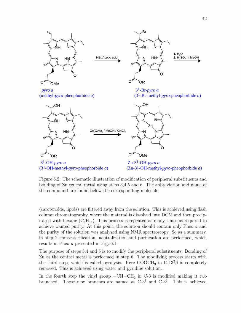
42
N HN
NNH
O
O OMe
N HN
NNH
O
OR
Br
O
N HN
NNH
O
OR
OH
O
N N
NN
O
O OMe
OH
Zn
31-OH-pyro a(31-OH-methyl-pyro-pheophorbide a)
pyro a(methyl-pyro-pheophorbide a)
Zn-31-OH-pyro a(Zn-31-OH-methyl-pyro-pheophorbide a)
31-Br-pyro a(31-Br-methyl-pyro-pheophorbide a)
HBr/Acetic acid1. H2O2. H2SO4 in MeOH
Zn(OAc)2 / MeOH / CHCl3
Figure 6.2: The schematic illustration of modification of peripheral substituents andbonding of Zn central metal using steps 3,4,5 and 6. The abbreviation and name ofthe compound are found below the corresponding molecule
(carotenoids, lipids) are filtered away from the solution. This is achieved using flashcolumn chromatography, where the material is dissolved into DCM and then precip-itated with hexane (C6H14). This process is repeated as many times as required toachieve wanted purity. At this point, the solution should contain only Pheo a andthe purity of the solution was analyzed using NMR spectroscopy. So as a summary,in step 2 transesterification, neutralization and purification are performed, whichresults in Pheo a presented in Fig. 6.1.
The purpose of steps 3,4 and 5 is to modify the peripheral substituents. Bonding ofZn as the central metal is performed in step 6. The modifying process starts withthe third step, which is called pyrolysis. Here COOCH3 in C-132β is completelyremoved. This is achieved using water and pyridine solution.
In the fourth step the vinyl group −CH−−CH2 in C-3 is modified making it twobranched. These new branches are named as C-31 and C-32. This is achieved
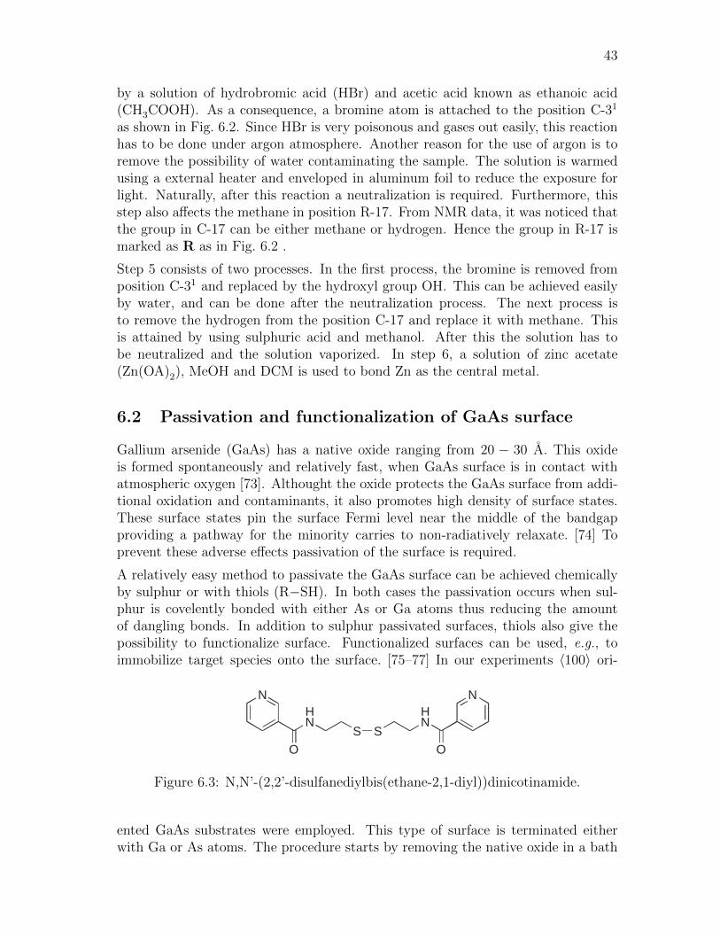
43
by a solution of hydrobromic acid (HBr) and acetic acid known as ethanoic acid(CH3COOH). As a consequence, a bromine atom is attached to the position C-31
as shown in Fig. 6.2. Since HBr is very poisonous and gases out easily, this reactionhas to be done under argon atmosphere. Another reason for the use of argon is toremove the possibility of water contaminating the sample. The solution is warmedusing a external heater and enveloped in aluminum foil to reduce the exposure forlight. Naturally, after this reaction a neutralization is required. Furthermore, thisstep also affects the methane in position R-17. From NMR data, it was noticed thatthe group in C-17 can be either methane or hydrogen. Hence the group in R-17 ismarked as R as in Fig. 6.2 .
Step 5 consists of two processes. In the first process, the bromine is removed fromposition C-31 and replaced by the hydroxyl group OH. This can be achieved easilyby water, and can be done after the neutralization process. The next process isto remove the hydrogen from the position C-17 and replace it with methane. Thisis attained by using sulphuric acid and methanol. After this the solution has tobe neutralized and the solution vaporized. In step 6, a solution of zinc acetate(Zn(OA)2), MeOH and DCM is used to bond Zn as the central metal.
6.2 Passivation and functionalization of GaAs surface
Gallium arsenide (GaAs) has a native oxide ranging from 20 − 30 A. This oxideis formed spontaneously and relatively fast, when GaAs surface is in contact withatmospheric oxygen [73]. Althought the oxide protects the GaAs surface from addi-tional oxidation and contaminants, it also promotes high density of surface states.These surface states pin the surface Fermi level near the middle of the bandgapproviding a pathway for the minority carries to non-radiatively relaxate. [74] Toprevent these adverse effects passivation of the surface is required.
A relatively easy method to passivate the GaAs surface can be achieved chemicallyby sulphur or with thiols (R−SH). In both cases the passivation occurs when sul-phur is covelently bonded with either As or Ga atoms thus reducing the amountof dangling bonds. In addition to sulphur passivated surfaces, thiols also give thepossibility to functionalize surface. Functionalized surfaces can be used, e.g., toimmobilize target species onto the surface. [75–77] In our experiments 〈100〉 ori-
N
O
HN
S
N
O
HN
S
Figure 6.3: N,N’-(2,2’-disulfanediylbis(ethane-2,1-diyl))dinicotinamide.
ented GaAs substrates were employed. This type of surface is terminated eitherwith Ga or As atoms. The procedure starts by removing the native oxide in a bath
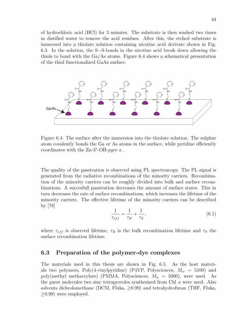
44
of hydrochloric acid (HCl) for 3 minutes. The substrate is then washed two timesin distilled water to remove the acid residues. After this, the etched substrate isimmersed into a thiolate solution containing nicotine acid derivate shown in Fig.6.3. In the solution, the S−S-bonds in the nicotine acid break down allowing thethiols to bond with the Ga/As atoms. Figure 6.4 shows a schematical presentationof the thiol functionalized GaAs surface.
N
OHN
S
N
OHN
S
N
OHN
S
N
OHN
S
N
OHN
S
N
OHN
S
N
OHN
S
N
OHN
S
N
OHN
S
N
OHN
S
N
OHN
S
N
OHN
SGa/As
Figure 6.4: The surface after the immersion into the thiolate solution. The sulphuratom covalently bonds the Ga or As atoms in the surface, while pyridine efficientlycoordinates with the Zn-31-OH-pyro a .
The quality of the passivation is observed using PL spectroscopy. The PL signal isgenerated from the radiative recombinations of the minority carriers. Recombina-tion of the minority carriers can be roughly divided into bulk and surface recom-binations. A succesfull passivation decreases the amount of surface states. This inturn decreases the rate of surface recombinations, which increases the lifetime of theminority carriers. The effective lifetime of the minority carriers can be describedby [78]
1
τeff=
1
τB+
1
τS, (6.1)
where τeff is observed lifetime, τB is the bulk recombination lifetime and τS thesurface recombination lifetime.
6.3 Preparation of the polymer-dye complexes
The materials used in this thesis are shown in Fig. 6.5. As the host materi-als two polymers, Poly(4-vinylpyridine) (P4VP, Polysciences, Mw = 5100) andpoly(methyl methacrylate) (PMMA, Polysciences, Mw = 5000), were used. Asthe guest molecules two zinc tetrapyrroles synthesized from Chl a were used. Alsosolvents dichrolomethane (DCM, Fluka, ≥0.99) and tetrahydrofuran (THF, Fluka,≥0.99) were employed.
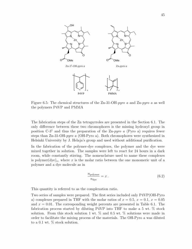
45
n
P4VPn
PMMA
N N
NN
O
O OMe
OH
Zn
Zn-31-OH-pyro a
N N
NN
O
O OMe
Zn
Zn-pyro a
Figure 6.5: The chemical structures of the Zn-31-OH-pyro a and Zn-pyro a as wellthe polymers P4VP and PMMA
The fabrication steps of the Zn tetrapyrroles are presented in the Section 6.1. Theonly difference between these two chromophores is the missing hydroxyl group inposition C-31 and thus the preparation of the Zn-pyro a (Pyro a) requires fewersteps than Zn-31-OH-pyro a (OH-Pyro a). Both chromophores were synthesized inHelsinki University by J. Helaja’s group and used without additional purification.
In the fabrication of the polymer-dye complexes, the polymer and the dye weremixed together in solution. The samples were left to react for 24 hours in a darkroom, while constantly stirring. The nomenclature used to name these complexesis polymer(dye)x, where x is the molar ratio between the one monomeric unit of apolymer and a dye molecule as in
npolymer
ndye
= x . (6.2)
This quantity is referred to as the complexation ratio.
Two series of samples were prepared. The first series included only P4VP(OH-Pyroa) complexes prepared in THF with the molar ratios of x = 0.5, x = 0.1, x = 0.05and x = 0.01. The corresponding weight percents are presented in Table 6.1. Thefabrication process started by diluting P4VP into THF to make a 5 wt. % stocksolution. From this stock solution 1 wt. % and 0.5 wt. % solutions were made inorder to facilitate the mixing process of the materials. The OH-Pyro a was dilutedto a 0.1 wt. % stock solution.

46
Table 6.1: Series 1 - P4VP(OH-Pyro a)x complexesin THF. The complexation ratios and correspondingweight percent of the dye.
x Weight percent (wt. %)
0.5 75.90.1 38.60.05 230.01 5.5
In the second series, PMMA(Pyro a) and P4VP(Pyro a) complexes were preparedin order to study the effect of the host material in the fluorescence properties of thedye. The second series had in total 14 samples that composed of following weightpercents 1%, 2%, 4%, 6%, 8%, 10% and 12%. As the solvent DCM was used insteadof THF, since PMMA is insoluble in THF. First, both the polymers were diluted inDCM to prepare a 5 wt. % stock solution. The dye, Pyro a was diluted in DCM toprepare 0.1 wt. % stock solution.
All samples were cast on a glass substrate by spin coating, where a two step programwas utilized. In the first step, material was applied to the substrate and spinnedwith a rotation speed of 500/1000 revolutions per minute (rpm) for 40 seconds. Thesecond step consisted of drying the solvent with a rotation speed of 5000 rpm for30 seconds. In the first series the samples were spinned using two different rotationspeeds to study the relationship between the rotation speed and the film quality andthickness. In the second series the samples were spinned only with 1000 rpm rotationspeed. The thicknesses of the spinned films were analyzed by a Veeco Dektak 6Msurface profilometer.
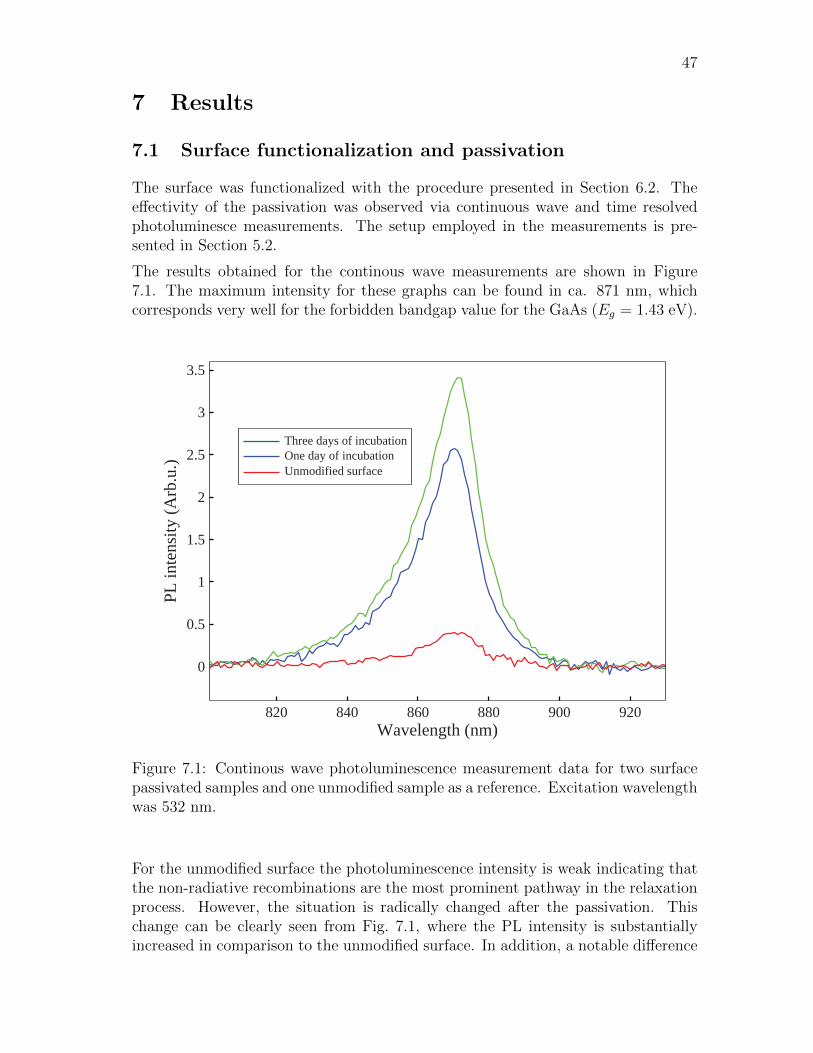
47
7 Results
7.1 Surface functionalization and passivation
The surface was functionalized with the procedure presented in Section 6.2. Theeffectivity of the passivation was observed via continuous wave and time resolvedphotoluminesce measurements. The setup employed in the measurements is pre-sented in Section 5.2.
The results obtained for the continous wave measurements are shown in Figure7.1. The maximum intensity for these graphs can be found in ca. 871 nm, whichcorresponds very well for the forbidden bandgap value for the GaAs (Eg = 1.43 eV).
820 840 860 880 900 920
0
0.5
1
1.5
2
2.5
3
3.5
PL in
tens
ity (A
rb.u
.)
Wavelength (nm)
Three days of incubationOne day of incubationUnmodified surface
Figure 7.1: Continous wave photoluminescence measurement data for two surfacepassivated samples and one unmodified sample as a reference. Excitation wavelengthwas 532 nm.
For the unmodified surface the photoluminescence intensity is weak indicating thatthe non-radiative recombinations are the most prominent pathway in the relaxationprocess. However, the situation is radically changed after the passivation. Thischange can be clearly seen from Fig. 7.1, where the PL intensity is substantiallyincreased in comparison to the unmodified surface. In addition, a notable difference
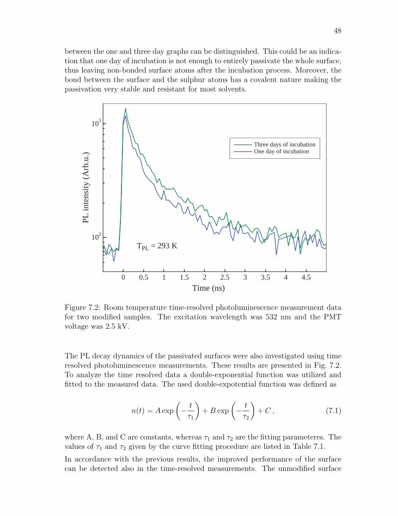
48
between the one and three day graphs can be distinguished. This could be an indica-tion that one day of incubation is not enough to entirely passivate the whole surface,thus leaving non-bonded surface atoms after the incubation process. Moreover, thebond between the surface and the sulphur atoms has a covalent nature making thepassivation very stable and resistant for most solvents.
PL in
tens
ity (A
rb.u
.)
Time (ns)0 0.5 1 1.5 2 2.5 3 3.5 4 4.5
102
103
TPL = 293 K
Three days of incubationOne day of incubation
Figure 7.2: Room temperature time-resolved photoluminescence measurement datafor two modified samples. The excitation wavelength was 532 nm and the PMTvoltage was 2.5 kV.
The PL decay dynamics of the passivated surfaces were also investigated using timeresolved photoluminescence measurements. These results are presented in Fig. 7.2.To analyze the time resolved data a double-exponential function was utilized andfitted to the measured data. The used double-expotential function was defined as
n(t) = A exp
(− t
τ1
)+B exp
(− t
τ2
)+ C , (7.1)
where A, B, and C are constants, whereas τ1 and τ2 are the fitting parameteres. Thevalues of τ1 and τ2 given by the curve fitting procedure are listed in Table 7.1.
In accordance with the previous results, the improved performance of the surfacecan be detected also in the time-resolved measurements. The unmodified surface
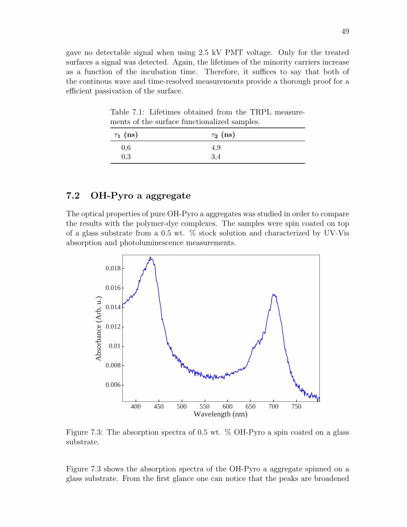
49
gave no detectable signal when using 2.5 kV PMT voltage. Only for the treatedsurfaces a signal was detected. Again, the lifetimes of the minority carriers increaseas a function of the incubation time. Therefore, it suffices to say that both ofthe continous wave and time-resolved measurements provide a thorough proof for aefficient passivation of the surface.
Table 7.1: Lifetimes obtained from the TRPL measure-ments of the surface functionalized samples.
τ1 (ns) τ2 (ns)
0,6 4,90,3 3,4
7.2 OH-Pyro a aggregate
The optical properties of pure OH-Pyro a aggregates was studied in order to comparethe results with the polymer-dye complexes. The samples were spin coated on topof a glass substrate from a 0.5 wt. % stock solution and characterized by UV-Visabsorption and photoluminescence measurements.
Wavelength (nm)400 450 500 550 600 650 700 750
0.006
0.008
0.01
0.012
0.014
0.016
0.018
Abs
orba
nce
(Arb
. u.)
Figure 7.3: The absorption spectra of 0.5 wt. % OH-Pyro a spin coated on a glasssubstrate.
Figure 7.3 shows the absorption spectra of the OH-Pyro a aggregate spinned on aglass substrate. From the first glance one can notice that the peaks are broadened

50
enveloping the smaller details under them. Another important detail is a very strongred shift of the Q band. This peak has shifted to ca. 710 nm, whereas the monomerQ band peak lies in 660 nm. All of these details reveal that the OH-Pyro a moleculesare in aggregated form and also that the aggregate is in amorphous state [41].
0.5
1
1.5
2
2.5
3
3.5
4
4.5
PL in
tens
ity (A
rb.u
.)
640 660 680 700 720 740Wavelength (nm)
Spin coated (Tmea = 30 K)Spin coated (Tmea = 293 K)
In solution (Tmea = 293 K)
640 660 680 700 720 740
0.02
0.06
0.1
0.14 Magnification
Figure 7.4: The photoluminescence spectra of 0.5 wt. % OH-Pyro a in THF solutionand spin coated on a glass substrate. Excitation wavelength was 400 nm.
Figure 7.4 shows the results obtained from the photoluminescence measuremets. TheCWPL measurements were done for two different samples: OH-Pyro a in solutionand spin coated films on glass. In addition, the spin coated sample was measuredin room temperature (Tmea = 293 K) and in cryo temperature (Tmea = 30 K). InFig. 7.4, the spin coated sample exhibit insignificant fluorescence in comparison tomolecules in a solution. Nevertheless, a magnified view of the graphs reveals twodistinct peaks in the sample when measured in a cryo temperature. The values ofthese peaks are ca. 660 nm and 710-760 nm. The 660 nm peak corresponds to theS1 → S0 transition and the broader peak around 710-760 nm could correspond tothe aggregate enhanced T1 → S0 transition. These same features are also observablein the data measured in the room temperature both the signal to noise ratio is muchmore worse.
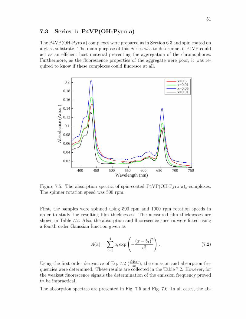
51
7.3 Series 1: P4VP(OH-Pyro a)
The P4VP(OH-Pyro a) complexes were prepared as in Section 6.3 and spin coated ona glass substrate. The main purpose of this Series was to determine, if P4VP couldact as an efficient host material preventing the aggregation of the chromophores.Furthermore, as the fluorescence properties of the aggregate were poor, it was re-quired to know if these complexes could fluoresce at all.
400 450 500 550 600 650 700 750
0.02
0.04
0.06
0.08
0.1
0.12
0.14
0.16
0.18
0.2
Wavelength (nm)
Abs
orba
nce
(Arb
.u.)
x=0.5x=0.01x=0.05x=0.01
Figure 7.5: The absorption spectra of spin-coated P4VP(OH-Pyro a)x-complexes.The spinner rotation speed was 500 rpm.
First, the samples were spinned using 500 rpm and 1000 rpm rotation speeds inorder to study the resulting film thicknesses. The measured film thicknesses areshown in Table 7.2. Also, the absorption and fluorescence spectra were fitted usinga fourth order Gaussian function given as
A(x) =4∑i=1
ai exp
(−(x− b1)2
c21
). (7.2)
Using the first order derivative of Eq. 7.2 (dA(x)dx
), the emission and absorption fre-quencies were determined. These results are collected in the Table 7.2. However, forthe weakest fluorescence signals the determination of the emission frequency provedto be impractical.
The absorption spectras are presented in Fig. 7.5 and Fig. 7.6. In all cases, the ab-

52
Wavelength (nm)
Abs
orba
nce
(Arb
.u.)
400 450 500 550 600 650 700 7500
0.02
0.04
0.06
0.08
0.1
0.12
0.14
0.16
0.18
0.2
x=0.5x=0.01x=0.05x=0.01
Figure 7.6: The absorption spectra of spin-coated P4VP(OH-Pyro a)x-complexes.The spinner rotation speed was 1000 rpm.
Table 7.2: The measured physical and optical properties of the spin coatedP4VP(OH-Pyro a) films.
Molar ratio Thickness (nm) Soret (nm) Q (nm) Emission (nm)
1000 rpm:
0.5 30 433.9 658.3 -0.1 35 433.4 656.4 6620.05 55 432.7 655.8 661.80.01 120 431.7 655 660.4
500 rpm:
0.5 20 434.5 658.9 -0.1 37 433.3 656.5 -0.05 125 432.3 655.9 6630.01 205 431.4 655.0 660.2
sorption spectra resembles more monomeric than aggregate absorption. In addition,the aggregate peak around 710 nm is missing. These details demonstrate that P4VPefficiently coordinates with the OH-Pyro a molecules preventing aggregation. Fur-thermore, the absorption of the aggregate is much more weaker in comparison to theP4VP(OH-Pyro a) complexes, albeit the amount of absorbing chromophores lying inthe light path is roughly equal. Therefore, this could indicate that the uncontrolledaggregation is also detrimental for the absorption properties of the substance.

53
From Table 7.2 it can be seen that the thickness of the film is increased as thedye concentration is decreased. Hence, the viscosity of the polymer-dye solution isproportional to the concentration of the dye. In most of the cases, the absorptionis increased as the film thickness increases. The only exception for this case canbe found in Fig. 7.5 for the x = 0.01, but a plausible result for this anomaly couldoriginate from bad beam aligment in the measurement. Additionally, the films werethicker with 500 rpm rotation speed, but surprisingly the absorption was roughlythe same. In addition, as the dye concentration decreases the peaks exhibit a
630 640 650 660 670 680 690 7000
50
100
150
200
250
300
350
400
450
500
Wavelength (nm)
Fluo
resc
ence
inte
nsity
(Arb
.u.)
x=0.5x=0.01x=0.05x=0.01
Figure 7.7: The fluorescence spectra of spin-coated P4VP(OH-Pyro a)x-complexes.The spinner rotation speed was 500 rpm, excitation wavelength was 420 nm andPMT voltage 800 V.
blueshift indicating that the excitonic coupling between the chromophores weakensas depicted by Eq. 3.9. This is again very reasonable, since statistically the distancebetween the chromophores should increase with decreasing dye concentration.
Figure 7.7 and 7.8 show the measured fluorescence spectra of the spin coated sam-ples. In the data a systematic error was present, which raised the signal bottomlevel. This was corrected by adjusting the zero level same for all the graphs. Inboth Figures, significant fluorescence signal can be detected only with the smallestdye concentration, i.e., with x = 0.01. Other dye concentrations exhibit a minimalfluorescence signal, but this very small in comparison to the x = 0.01 case. In addi-tion, the fluorescence signal detected from sample x = 0.01 is very strong comparedto the values obtained in the literature [79,80]. These reported results utilize weightconcentrations in the range of 0.5-2 wt. %. Therefore, P4VP(OH-Pyro a) complexesoffer a very tempting possibility as a gain material for lasers.

54
Wavelength (nm)
Fluo
resc
ence
inte
nsity
(Arb
.u.)
630 640 650 660 670 680 690 7000
100
200
300
400
500
600
x=0.5x=0.01x=0.05x=0.01
Figure 7.8: The fluorescence spectra of spin-coated P4VP(OH-Pyro a)x-complexes.The spinner rotation speed was 1000 rpm, excitation wavelength was 420 nm andPMT voltage 800 V.
7.4 Series 2: P4VP(Pyro a) vs. PMMA(Pyro a)
400 450 500 550 600 650 700 7500
0.05
0.1
0.15
0.2
0.25
0.3
0.35
Wavelength (nm)
Abs
orba
nce
(Arb
.u.)
1 wt. %2 wt. %4 wt. %6 wt. %8 wt. %10 wt. %12 wt. %
Figure 7.9: The absorption spectra of spin-coated P4VP(Pyro a)x-complexes.
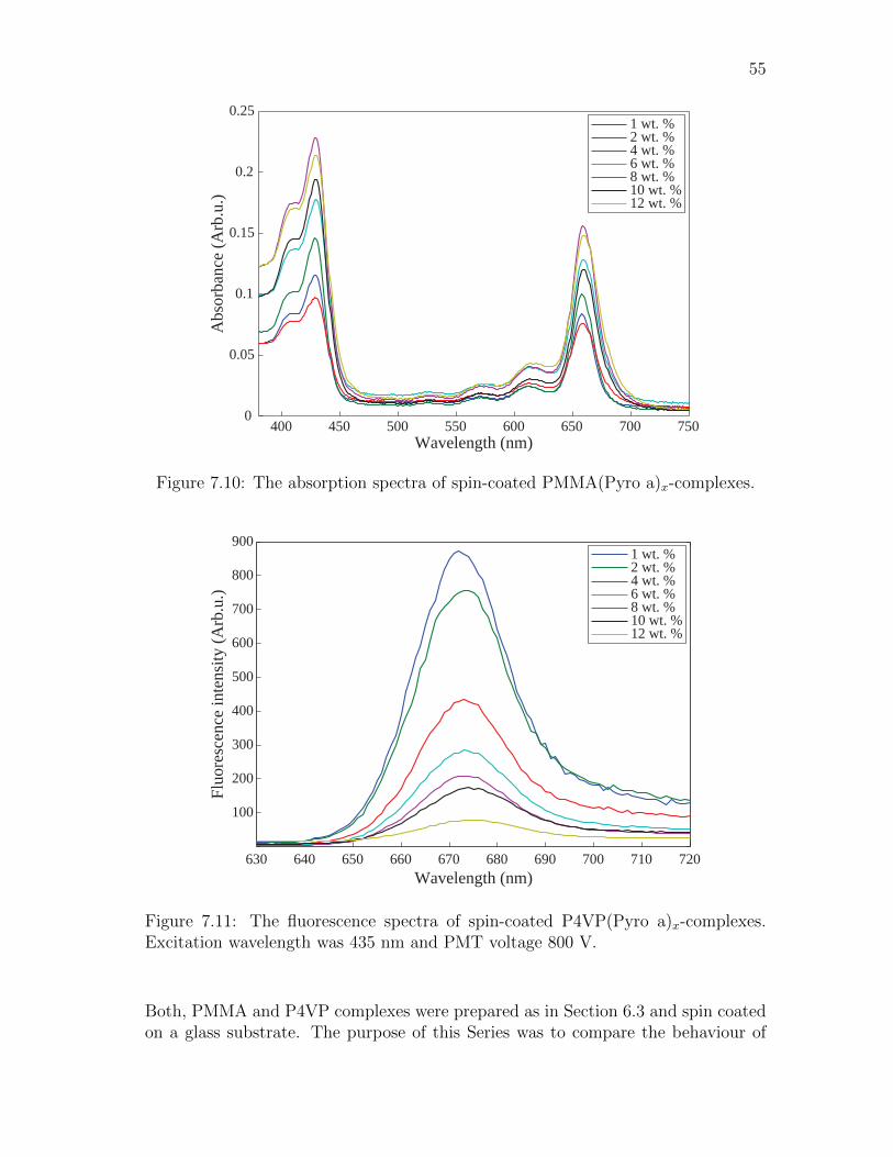
55
400 450 500 550 600 650 700 7500
0.05
0.1
0.15
0.2
0.25
Wavelength (nm)
Abs
orba
nce
(Arb
.u.)
1 wt. %2 wt. %4 wt. %6 wt. %8 wt. %10 wt. %12 wt. %
Figure 7.10: The absorption spectra of spin-coated PMMA(Pyro a)x-complexes.
630 640 650 660 670 680 690 700 710 720
100
200
300
400
500
600
700
800
900
Wavelength (nm)
Fluo
resc
ence
inte
nsity
(Arb
.u.)
1 wt. %2 wt. %4 wt. %6 wt. %8 wt. %10 wt. %12 wt. %
Figure 7.11: The fluorescence spectra of spin-coated P4VP(Pyro a)x-complexes.Excitation wavelength was 435 nm and PMT voltage 800 V.
Both, PMMA and P4VP complexes were prepared as in Section 6.3 and spin coatedon a glass substrate. The purpose of this Series was to compare the behaviour of

56
two different host materials. The hypothesis was that PMMA complexes shouldexhibit worse optical properties, since the coordination with the dye is more weaker.In addition, a different dye was utilized than in Series 1 in order to study, if thehydroxyl bond had any pronounced effect in the formation of the coordination bondbetween the dye and the molecule.
630 640 650 660 670 680 690 700 710 720
100
200
300
400
500
600
Wavelength (nm)
Fluo
resc
ence
inte
nsity
(Arb
.u.)
1 wt. %2 wt. %4 wt. %6 wt. %8 wt. %10 wt. %12 wt. %
Figure 7.12: The fluorescence spectra of spin-coated PMMA(Pyro a)x-complexes.Excitation wavelength was 435 nm and PMT voltage 800 V.
The absorption spectra of the P4VP(Pyro a) and PMMA(Pyro a) complexes isshown in Figs. 7.9 and 7.10 respectively. The Soret and Q absorption peaks weredetermined by fitting Eq. 7.2 as described earlier. Surprisingly, PMMA films do notexhibit any signs of aggregation. Somekind of sign of aggregation was expected, sincethe coordination bond between the carbonyl group of the polymer and the centralmetal of Pyro a is weak. However, the concentration of the dye is small, which couldmake the aggregation effects difficult to detect. Higher dye concentrations might beneeded to demonstrate this effect.
Another interesting difference found in the P4VP absorption spectra in Fig. 7.9 isa very large (ca. 10 nm) redshift in comparison to PMMA(Pyro a) and P4VP(OH-Pyro a) complexes (Figs. 7.10, 7.5 and 7.6). Since position C-31 is situated relativelyfar from the macrocycle, removing the hydroxyl group should not have a largeeffect in the electronic properties of the molecule. This assumption is supportedby the data obtained from the PMMA complexes, which do not exhibit any kindof red shift in comparison to P4VP(OH-Pyro a) complexes. The reason behindthis redshift, could lie in the efficient coordination bond between the Zn and the

57
pyridine, since strong coordination of the central metal has been shown to affectthe electronic structure of the macrocycle [20, 28]. To verify this a solvent spectrawould be required. Also, additional measurements between OH-Pyro a and Pyro achromophores could elucidate this phenomenon.
The fluorescence spectra of the P4VP(Pyro a) and PMMA(Pyro a) complexes areshown in Figs. 7.11 and 7.12 respectively. The fluorescence of the P4VP complexesis much stronger in all cases when compared to the PMMA complexes. Hence,even though the aggregation effects were not noticiable from the absorption spectra,fluorescence spectra clearly demonstrates the inferior performance of the PMMAas a host. Furtmermore, the observed redshift in the absorption spectra for theP4VP(Pyro a) complex, is also visible in the fluorescence spectra.
Table 7.3: Wavelengths of the absorption and emission peaksof the spinned P4VP(Pyro a) and PMMA(Pyro a) films.
Weight percent Soret (nm) Q (nm) Emission (nm)
P4VP(Pyro a):
1 wt. % 436.9 666.1 672.32 wt. % 437.2 666 673.64 wt. % 437 666.1 673.16 wt. % 436.9 666.3 673.78 wt. % 437 666.1 673.310 wt. % 437 666.4 67412 wt. % 437.3 666.6 674.3
PMMA(Pyro a):
1 wt. % 428.3 658.3 664.72 wt. % 428.6 658.5 664.64 wt. % 428.7 659 667.26 wt. % 429.2 659.8 667.18 wt. % 428.9 659.5 667.610 wt. % 429 659.8 668.712 wt. % 429.2 660.3 -
58
8 Conclusions
In this thesis, the first steps to integrate Zinc tetrapyrrole molecules with modernsemiconductor devices are taken. This thesis introduces crucial concepts and prop-erties required to understand the properties of molecular aggregates and guest-hostmaterials. Also the underlying theory of energy transfer is presented. Althought,RET is a known phenomenon the information concerning the QED treatment isfragmented and obtaining a general view can be difficult. Hence, the author wantedto collect the available information and present it in a cohesive and understandablemanner for others to study, and enjoy learning as much as I have.
The preliminary results demonstrated in this thesis appear promising. The en-visioned device exploting the introduced concepts and results, could consist ofAlGaAs/GaAs/AlGaAs quantum well with organic layer situated on top. Crucialfactor in this device lies in the barrier thickess. Usually the barriers need to beatleast twice the thickness of the QW itself. If the barrier is not thick enough, thequantum confinement is not strong enough and tunneling of the electron out fromthe QW could occur. However, if the barrier is too thick, the coupling between theorganic layer and the QW will not be sufficiently strong, since the energy transferbetween a QW and a molecule has the characteristic R−4 distance dependency. Butwith the developed passivation technique this problem might hopefully be circum-vented, since it allows the fabrication of even thinner barriers exhibiting the samequantum confinement as the thicker counterparts.
The results from the passivation could be still investigated more thoroughly by scan-ning tunneling microscope (STM) or photoelectron spectroscopy (XPS). Especially,XPS could yield additional information about the bonding strenghts between thethiol and the Ga/As atoms. With the help of STM the pyridine molecules could beidentified on top the surface. This could be used to identify the surface topographywith an atomic resolution. In addition, the deposition of a Zn tetrapyrroles on tothe functionalized surface appears to be intesting possibility, since the functionalizedsurface offers the possibility to deposit a monolayer of target molecules on top ofthe substrate. Therefore, this possibility will most likely be tested in future.
The fluorescence studies of the polymer-dye complexes could also be judged suc-cesfull. With the help of supramolecular design, the optical properties of the chro-mophores can be drastically improved when compared to pure Zn tetrapyrrole ag-gregates. Hence, polymer-dye complexes seem to be the most prominent candi-date in creating sufficient fluorescence in solid state. Furthermore, when comparingP4VP and PMMA with each other, P4VP is a much better host material for Zntetrapyrroles. The underlying reason for this difference most probably lies in theefficient ligation between central metal and pyridine, which reduces the aggregationof the molecules.
PMMA is the most commonly used host material in solid state lasers and the rho-damine family molecules are the most employed fluorophores. However, as statedearlier the used dye concentrations are very small in comparison to the results ob-
59
tained in this thesis. Therefore, Zn tetrapyrroles and P4VP could offer new in-teresting possibilities in this area. In addition, the used Zn tetrapyrroles exhibitan ideal three-state system behaviour reducing the reabsorbtion effects present inrhodamine dyes. Furthermore, with a relative small modifications to the moleculethe lasing wavelength can be changed offering the possibility for tailorability in thelaser application. Finally, the fabrication process, i.e., spin coating of the materialon top of the substrate, is ideal for distributed feedback (DFB) lasers.
The pure aggregates exhibit peculiar and interesting properties, e.g., self-assembly inlarger supramolecular structures. These kind of assemblies could posses very rapidconduction mechanisms or even charge transfer as in their natural counterparts.In addition, combining these photosynthetic pigments with plasmonics could offernew sensor possibilities or waveguides. However, to monitor these effects requires aspecilized tool, such as scanning near-field optical microscope (SNOM).
The results presented in this thesis will most likely be published in a peer reviewedjournal, especially the work done with the fluorescent polymer-dye complexes. Nextgoal is to fabricate a proof of concept laser utilizing the earlier discussed benefits.The final aim of this reseach project is to developing a device, capable of collectingthe excitation energy of the chromophores and transform it to electricity.
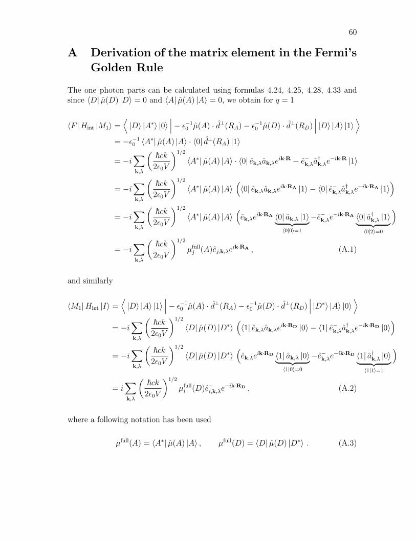
60
A Derivation of the matrix element in the Fermi’s
Golden Rule
The one photon parts can be calculated using formulas 4.24, 4.25, 4.28, 4.33 andsince 〈D| µ(D) |D〉 = 0 and 〈A| µ(A) |A〉 = 0, we obtain for q = 1
〈F |Hint |M1〉 =⟨|D〉 |A∗〉 |0〉
∣∣∣− ε−10 µ(A) · d⊥(RA)− ε−1
0 µ(D) · d⊥(RD)∣∣∣ |D〉 |A〉 |1〉⟩
= −ε−10 〈A∗| µ(A) |A〉 · 〈0| d⊥(RA) |1〉
= −i∑k,λ
(~ck
2ε0V
)1/2
〈A∗| µ(A) |A〉 · 〈0| ek,λak,λeik·R − e−k,λa†k,λe
−ik·R |1〉
= −i∑k,λ
(~ck
2ε0V
)1/2
〈A∗| µ(A) |A〉(〈0| ek,λak,λeik·RA |1〉 − 〈0| e−k,λa
†k,λe
−ik·RA |1〉)
= −i∑k,λ
(~ck
2ε0V
)1/2
〈A∗| µ(A) |A〉(ek,λe
ik·RA 〈0| ak,λ |1〉︸ ︷︷ ︸〈0|0〉=1
−e−k,λe−ik·RA 〈0| a†k,λ |1〉︸ ︷︷ ︸
〈0|2〉=0
)
= −i∑k,λ
(~ck
2ε0V
)1/2
µfullj (A)ej,k,λe
ik·RA , (A.1)
and similarly
〈M1|Hint |I〉 =⟨|D〉 |A〉 |1〉
∣∣∣− ε−10 µ(A) · d⊥(RA)− ε−1
0 µ(D) · d⊥(RD)∣∣∣ |D∗〉 |A〉 |0〉⟩
= −i∑k,λ
(~ck
2ε0V
)1/2
〈D| µ(D) |D∗〉(〈1| ek,λak,λeik·RD |0〉 − 〈1| e−k,λa
†k,λe
−ik·RD |0〉)
= −i∑k,λ
(~ck
2ε0V
)1/2
〈D| µ(D) |D∗〉(ek,λe
ik·RD 〈1| ak,λ |0〉︸ ︷︷ ︸〈1|0〉=0
−e−k,λe−ik·RD 〈1| a†k,λ |0〉︸ ︷︷ ︸
〈1|1〉=1
)
= i∑k,λ
(~ck
2ε0V
)1/2
µfulli (D)e−i,k,λe
−ik·RD , (A.2)
where a following notation has been used
µfull(A) = 〈A∗| µ(A) |A〉 , µfull(D) = 〈D| µ(D) |D∗〉 . (A.3)
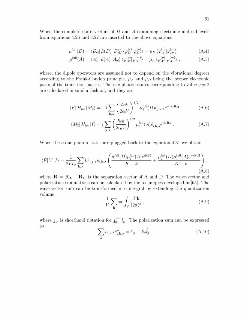
61
When the complete state vectors of D and A containing electronic and sublevelsfrom equations 4.26 and 4.27 are inserted to the above equations
µfull(D) = 〈Del| µ(D) |D∗el〉 〈ϕ(r)D |ϕ
(n)D∗〉 = µD 〈ϕ(r)
D |ϕ(n)D∗〉 (A.4)
µfull(A) = 〈A∗el| µ(A) |Ael〉 〈ϕ(p)A∗ |ϕ
(m)A 〉 = µA 〈ϕ(p)
A∗ |ϕ(m)A 〉 , (A.5)
where, the dipole operators are assumed not to depend on the vibrational degreesaccording to the Frank-Condon principle, µA and µD being the proper electronicparts of the transition matrix. The one photon states corresponding to value q = 2are calculated in similar fashion, and they are
〈F |Hint |M2〉 = −i∑k,λ
(~ck
2ε0V
)1/2
µfullj (D)ej,k,λe
−ik·RD (A.6)
〈M2|Hint |I〉 = i∑k,λ
(~ck
2ε0V
)1/2
µfulli (A)e−i,k,λe
ik·RA . (A.7)
When these one photon states are plugged back to the equation 4.31 we obtain
〈F |V |I〉 =1
2V ε0
∑k,λ
ke−i,k,λej,k,λ
(µfulli (D)µfull
j (A)eik·R
K − k+µfullj (D)µfull
i (A)e−ik·R
−K − k
),
(A.8)where R = RA − RD is the separation vector of A and D. The wave-vector andpolarization summations can be calculated by the techniques developed in [65]. Thewave-vector sum can be transformed into integral by extending the quantizationvolume
1
V
∑k
⇒∫V
d3k
(2π)3, (A.9)
where∫V
is shorthand notation for∫∞
0
∫Ω
. The polarization sum can be expressedas ∑
λ
ei,k,λe−j,k,λ = δij − ~ki~kj , (A.10)
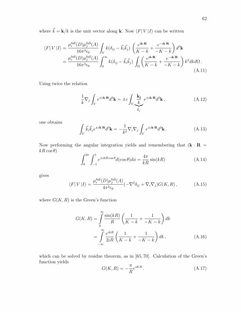
62
where ~k = k/k is the unit vector along k. Now 〈F |V |I〉 can be written
〈F |V |I〉 =µfulli (D)µfull
j (A)
16π3ε0
∫V
k(δij − ~ki~kj)(eik·R
K − k+
e−ik·R
−K − k
)d3k
=µfulli (D)µfull
j (A)
16π3ε0
∫ ∞0
k(δij − ~ki~kj)∫
Ω
(eik·R
K − k+
e−ik·R
−K − k
)k2dkdΩ .
(A.11)
Using twice the relation
1
k∇j
∫V
e±ik·Rd3k = ±i∫V
kj
k︸︷︷︸~kj
e±ik·Rd3k , (A.12)
one obtains ∫V
~ki~kje±ik·Rd3k = − 1
k2∇i∇j
∫V
e±ik·Rd3k . (A.13)
Now performing the angular integration yields and remembering that (k · R =kR cos θ) ∫ 2π
0
∫ 1
−1
e±ikR cos θd(cos θ)dφ =4π
kRsin(kR) (A.14)
gives
〈F |V |I〉 =µfulli (D)µfull
j (A)
4π2ε0(−∇2δij +∇i∇j)G(K,R) , (A.15)
where G(K,R) is the Green’s function
G(K,R) =
∞∫0
sin(kR)
R
(1
K − k+
1
−K − k
)dk
=
∞∫−∞
eikR
2iR
(1
K − k+
1
−K − k
)dk , (A.16)
which can be solved by residue theorem, as in [65, 70]. Calculation of the Green’sfunction yields
G(K,R) = − πReiKR . (A.17)

63
Completing the vector calculus in A.15 results in an expression
〈F |V |I〉 = µfulli (D)Vij(K,R)µfull
j (A)
= µfulli (D)µfull
j (A)K3eiKR
4πε0
[(δij − 3~Ri
~Rj
)( 1
K3R3− i
K2R2
)− (δij − ~Ri
~Rj)1
KR
].
(A.18)
64
References
[1] A.M. Humphrey. Chlorophyll. Food Chemistry, Vol. 5, Issue 1, pp. 57-67, 1980.
[2] B. Grimm, R. J. Porra, W. Rudiger and H. Scheer. Chlorophylls and Bacteri-ochlorophylls. Netherlands, Springer, 2006.
[3] T. Markvart and L. Castaner. Practical Handbook of Photovoltaics: Fundamen-tals and Applications. United Kingdom, Elsevier, 2003.
[4] W. S. Steed and J. L. Atwood. Supramolecular Chemistry. United Kingdom,Wiley, 2000.
[5] B. O’Regan and M. Gratzel. A low-cost, high-efficiency solar cell based on dye-sensitized colloidal TiO2 films. Nature, Vol. 353, pp. 737-740, 1991.
[6] P. Bhattacharya. Semiconductor Optoelectronic Devices. United States,Prentice-Hall Inc., 2nd. Edition, 1997.
[7] I. L. Medintz, A. R. Clapp, H. Mattoussi, E. L. Goldman, B. Fisher and J.M. Mauro. Self-assembled nanoscale biosensors based on quantum dot FRETdonors. Nature, Vol. 2, pp. 630-638, 2003.
[8] M. Achermann, M. A. Petruska, S. Kos, D. L. Smith, D. D. Koleske and V.Klimov. Energy-Transfer pumping of nanocrystals using an epitaxial quantumwell. Nature, Vol. 429, pp. 642-646, 2004.
[9] P. Atkins and J. de Paula. Atkins’ Physical Chemistry. United Kingdom, OxfordUniversity Press, 8th. Edition 2006.
[10] A. Sharma and S. G. Schulman. Introduction to fluorescence spectroscopy.United States, Wiley, 1999.
[11] J. M. Hollas. Modern Spectroscopy. United Kingdom, Wiley, 4th. Edition, 2003.
[12] B. Valeur. Molecular Fluorescence - Principles and Applications. Germany, Wi-ley, 2002.
[13] W. Schnabel. Polymers and light. Germany, Wiley, 2007.
[14] M. Warren and A. Smith. Tetrapyrroles: Birth, Life and Death. United King-dom, Springer, 2009.
[15] F. Salisbury and C. Ross. Plant Physiology. United Kingdom, Brooks Cole, 4th.Edition, 1991.
[16] H. Scheer, Chlorophylls. CRC Press, Boca Raton, 1991
[17] J. Deisenhofer, O. Epp, K. Miki, R. Huber and H. Michel. Structure of theprotein subunits in the photosynthetic reaction centre of Rhodopseudomonasviridis at 3 A resolution. Nature, Vol. 318, pp. 618-624, 1985.
65
[18] J. Helaja, K. Hyvarinen, S. Heikkinen, I. Kilpelainen and P. H. Hynninen.Solution structures of 132-methoxychlorophyll a epimers. Journal of MolecularStructure, Vol. 354, Issue 1, pp. 71,74-75,78, 1995.
[19] J. Helaja, A. Y. Tauber, I. Kilpelainen and P. H. Hynninen. Novel Model Com-pounds for Photoinduced Electron Transfer; Structures of the Folded Conform-ers of Zinc(II)-Pyropheophytin-Anthraquinone Dyads. Magnetic Resonance inChemistry, Vol. 35, pp. 619-628, 1997.
[20] L. P. Vernon and G. R. Seely. The Chlorophylls. New York, Academic Press,1966.
[21] C. B. Storm and Y. Teklu. Nitrogen-hydrogen tautomerism in porphyrines andchlorines. Journal of American Chemical Society, Vol. 94, Issue 5, pp. 1745-1747, 1972.
[22] J. Juselius and D. Sundholm. The aromatic pathways of porphins, chlorins andbacteriochlorins. Physical Chemistry Chemical Physics, Vol. 2, pp. 2145-2151,2000.
[23] M. Gouterman. Spectra of porphyrins. Journal of Molecular Spectroscopy, Vol.6, pp. 138-163, 1961.
[24] M. Gouterman. Spectra of porphyrins: Part III. Self-consistent molecular or-bital calculations of porphyrin and related ring systems. Journal of MolecularSpectroscopy, Vol. 16, Issue 2, pp. 415-450, 1965.
[25] D. Sundholm. Density functional theory calculations of the visible spectrum ofchlorophyll a. Chemical Physics Letters, Vol. 302, Issues 5-6, pp. 480-484, 1999.
[26] J. Hasegawa, Y. Ozeki, K. Ohkawa, M. Hada and H. Nakatsuji. TheoreticalStudy of the Excited States of Chlorin, Bacteriochlorin, Pheophytin a, andChlorophyll a by the SAC/SAC-CI Method. The Journal of Physical ChemistryB, Vol. 102 (7), pp. 1320-1326, 1998.
[27] L. R. Milgrom. The Colours of Life: An Introduction to the Chemistry of Por-phyrins and Related Compounds. United Staes, Oxford University Press, 1997.
[28] D. Dolphin. The Porphyrins III, Physical Chemistry, Part A. New York, Aca-demic Press, 1978.
[29] D. Vavilin, H. Xu, S. Lin and W. Vermaas. Energy and electron transfer in pho-tosystem II of a chlorophyll b-containing Synechocystis sp. PCC 6803 mutant..Biochemistry, Vol. 42, pp. 1731-1746, 2003.
[30] H. Tamiaki, T. Miyatake, R. Tanikaga, A. R. Holzwarth and K. Schaffner. Self-Assembly of an Artificial Light-Harvesting Antenna: Energy Transfer from aZinc Chlorin to a Bacteriochlorin in a Supramolecular Aggregate. AngewandteChemie International, Vol. 35, Issue 7, pp. 772-774, 2003.
66
[31] R. Blankenship, M. T. Madigan and C. E. Bauer. Anoxygenic PhotosyntheticBacteria. Dordrecht, Kluwer Academic Publishers, 1995.
[32] G. Blauer and H. Sund. Optical Properties and Structure of Tetrapyrrols. Lon-don, De Gruyter, 1985.
[33] J. P. Allen, G. Feher, T. O. Yeates, H. Komiya and D. C. Rees. Structure ofthe reaction center from Rhodobacter sphaeroides R-26: The protein subunits.PNAS, Vol. 84, pp. 6162-6166, 1987.
[34] A. W.D. Larkum and M. Kuhl. Chlorophyll d: the puzzle resolved. Trends inPlant Science, Vol. 10, Issue 8, pp. 355-357, 2005.
[35] S. S. Brody and E. Rabinowitch. Excitation Lifetime of Photosynthetic Pig-ments in vitro and in vivo. Science, Vol. 125, pp. 555-557, 1957.
[36] H. Van Amerongen, L. Valkunas and R. Van Grondelle. Photosynthetic Exci-tons. Singapore, World Scientific Publishing, 2000.
[37] K. N. Solovyov and E. A. Borisevich. Intramolecular heavy-atom effect in thephotophysics of organic molecules. Physics-Uspekhi, Vol. 48 (3), pp. 231-253,2005.
[38] L. L. Shipman, J. R. Norris and J. J. Katz. Quantum mechanical formalismfor computation of the electronic spectral properties of chlorophyll aggregates.Journal of Phyrical Chemistry, Vol. 80, pp. 877-882, 1976.
[39] G. C. Papageorgiou and R. Van Govindjee. Chlorophyll a Fluorescence. Nether-lands, Springer, 2004.
[40] J. C. de Paula, J. H. Robblee and R. F. Pasternacka. Aggregation of chlorophylla probed by resonance light scattering spectroscopy. Biophysical Journal, Vol.68, Issue 1, pp. 335-341, 1995.
[41] T. S. Balaban, H. Tamiaki, A. R. Holzwarth. Chlorins Programmed for Self-Assembly. Topics in Current Chemistry, Vol. 258, pp. 1-38, 2005.
[42] V. Huber, S. Sengupta and F. Wurhner. Structure-Property Relationships forSelf-Assembled Zinc Chlorin Light-Harvesting Dye Aggregates. Chemistry - AEuropean Journal, Vol. 14, Issue 26, pp. 7791-7807, 2008.
[43] J. Standfuss, A. C. Terwisscha van Scheltinga, M. Lamborghini and W.Kuhlbrandt. Mechanisms of photoprotection and nonphotochemical quenchingin pea lightharvesting complex at 2.5 A resolution. European Molecular BiologyOrganization (EMBO) Journal, Vol. 24, pp. 919-928, 2005.
[44] J. Matysik, C. Soede-Huijbregts, M. Baldus, J. Raap, J. Lugtenburg, P. Gast,H. J.. van Gorkom, A. J. Hoff and H. J. M. de Groot. Ultrahigh Field MAS

67
NMR Dipolar Correlation Spectroscopy of the Histidine Residues in Light-Harvesting Complex II from Photosynthetic Bacteria Reveals Partial InternalCharge Transfer in the B850/His Complex. Journal of American Chemical So-ciety, Vol. 123, Issue 20, pp. 4803-4809, 2001.
[45] H. Kirchoff. H.-J. Hinz and J. Rosgen. Aggregation and fluorescence quench-ing of chlorophyll a of the light-harvesting complex II from spinach in vitro.Biochimica et Biophysica Acta (BBA) - Bioenergetics, Vol. 1606, Issues 1-3,pp. 105-116, 2003.
[46] T. S. Balaban, J. Leitich, A. R. Holzwarth and K. Schaffner. AutocatalyzedSelf-Aggregation of (31R)-[Et,Et]Bacteriochlorophyll cF Molecules in NonpolarSolvents. Analysis of the Kinetics. Journal of Physical Chemistry B, Vol. 104,pp. 1362-1372, 2000.
[47] A. S. Davydov. The theory of molecular excitons. Soviet Physics Uspekhi, Vol.82, pp. 393-448, 1964.
[48] M. Kasha, H. R. Rawls and M. A. El-Bayoumi. The exciton model in molecularspectroscopy. Pure and Applied Chemistry, Vol. 11, No. 3-4, pp. 371-392, 1965.
[49] D. Mobius. Scheibe aggregates. Advanced Materials, Vol. 7, Issue 5, pp. 437-444,1995.
[50] F. Perrin. Theorie quantique des transferts d’activation entre molecules dememe espece. Cas des solutions fluorescentes. Ann. Phys., Vol. 17, pp. 283-314, 1932.
[51] T. Forster. Energiewanderung und Fluoreszenz (Energy transfer and fluores-cence). Naturwissenschaffen, Vol. 6, pp. 166-175, 1946.
[52] T. Forster. Zwischenmolekulare Energiewanderung und Fluoreszenz (Inter-molecular energy migration and fluorescence). Ann. Phys., Vol. 2, pp. 55-75,1948.
[53] T. Forster. Experimentelle und theoretische Untersuchung des zwischenmoleku-laren Ubergangs von Elektronenanregunngsenergie (Experimental and theoreti-cal study of the intermolecular transfer of excitation energy). Z. Naturforsch,Vol. 4A, pp. 321-327, 1949.
[54] Y. P. Ho, H. H. Chen, K. W. Leong and T-H. Wang. Evaluating the intracellularstability and unpacking of DNA nanocomplexes by quantum dots-FRET. Journalof Controlled Release, Vol. 116, Issue 1, pp. 83-89, 2006.
[55] B. Tang, L. Cao, K. Xu, L. Zhuo, J. Ge, Q. Li and L. Yu. A New Nanobiosensorfor Glucose with High Sensitivity and Selectivity in Serum Based on Fluores-cence Resonance Energy Transfer (FRET) between CdTe Quantum Dots andAu Nanoparticles. Chemistry - A European Journal, Vol. 14, Issue 12, pp. 3637-3644, 2008.
68
[56] P. I. Bastiaens and T. M. Jovin. Microspectroscopic imaging tracks the intra-cellular processing of a signal transduction protein: fluorescent-labeled proteinkinase C beta I. PNAS, Vol. 93, no. 16, pp. 8407-8412, 1996.
[57] C. S. Yun, A. Yavier, T. Jennings, M. Fisher, S. Hira, S. Peterson B. Hopkins,N. O. Reich, and G. F. Strouse. Nanometal Surface Energy Transfer in OpticalRulers, Breaking the FRET Barrier. Journal of American Chemical Society,Vol. 127, pp. 3115-3119, 2005.
[58] T. Franzl, T. A. Klar, S. Schietinger, A. L. Rogach and J. Feldmann. ExcitonRecycling in Graded Gap Nanocrystal Structures. Nano Letters, Vol. 4, pp.1599-1603, 2004.
[59] D. L. Andrews and A. A. Demidov. Resonance Energy Transfer. United King-dom, Wiley, 1999.
[60] P. G. Wu and L. Brand. Resonance Energy Transfer: Methods and Applications.Analytical Biochemistry, Vol. 218, no. 1, pp. 1-13, 1994.
[61] T. Forster. Fluoreszenz organischer Verbindungen (Fluorescence of organiccompounds). Gottingen: Vandenhoeck & Ruprecht, pp. 312, 1951.
[62] L. Novotny and B. Hecht. Principles of Nano-Optics. United Kingdom, Cam-bridge University Press, 2006.
[63] R. M. Clegg. Fluorescence resonance energy transfer. Current Opinion inBiotechnology, Vol. 6, Issue 1, pp. 103-110, 1995.
[64] B. W. Van Der Meer, G. I. Coker and S.-Y. Chen. Resonance Energy Transfer,Theory and Data. New York, Wiley, 1994.
[65] D. P. Craig and T. Thirunamachandran. Molecular Quantum Electrodynamics.United Kingdom, Dover Publications, 1998.
[66] F. Schwabl. Quantum Mechanics. The Netherlands, Springer, 3rd. Edition,2002.
[67] A. Salam. A General Formula for the Rate of Resonant Transfer of EnergyBetween two Electric Multipole Moments of Arbitrary Order Using MolecularQuantum Electrodynamics. Journal of Chemical Physics, Vol. 122, 044112, 2005.
[68] D. L. Andrews and J. M. Leeder. Resonance Energy Transfer: When a DipoleFails. Journal of Chemical Physics, Vol. 130, 184504, 2009.
[69] F. Schwabl. Advanced Quantum Mechanics. Germany, Springer, 2nd. Edition,2000.
[70] G. J. Daniels, R. D. Jenkins, D. S. Bradshaw and D. L. Andrews. ResonanceEnergy Transfer: The Unified Theory Revisited. Journal of Chemical Physics,Vol. 119, Number 4, 2003.
69
[71] M. D. Galaninin. Luminescence of molecules and crystals. United Kingdom,Cambridge International Science Publishing, 1996.
[72] R. E. Dale, J. Eisinger and W. E. Blumberg. The orientational freedom ofmolecular probes. The orientation factor in intramolecular energy transfer. Bio-physical Journal, Vol. 26, pp.161-193, 1979.
[73] D. A. Allwood, R. T. Carlineb, N. J. Masona, C. Pickeringb, B. K. Tannercand P. J. Walkera. Characterization of oxide layers on GaAs substrates. ThinSolid Films, Vol. 364, Issues 1-2, pp. 33-39, 2000.
[74] C. J. Sandroff, R. N. Nottenburg. J.-C. Bischoff and R. Bhat. Dramatic en-hancement in the gain of a GaAs/AlGaAs heterostructure bipolar transistorby surface chemical passivation. Applied Physics Letters, Vol. 51, Issue 1, pp.33-35, 1987.
[75] V. Bessolova, M. Lebedeva, A. Ivankovb, W. Bauhoferb and D. Zahnc. Elec-tronic properties of GaAs(100) surface passivated in alcoholic sulfide solutions.Applied Surface Science, Vol. 133, Issues 1-2, pp. 17-22, 1998.
[76] A. Dreas-Wlodarczak, M. Mullneritsch, T. Juffmann, C. Cioffi, M. Arndtand M. Mayor. Immobilization of Zinc Porphyrin Complexes on Pyridine-Functionalized Glass Surfaces. Langmuir, Vol. 26 (13), pp. 10822-10826, 2010.
[77] J. J. Dubowski, R. Voznyy and G. M. Mashall. Molecular self-assembly andpassivation of GaAs (0 0 1) with alkanethiol monolayers: A view towards bio-functionalization. Applied Surface Science, Vol. 256, Issue 19, pp. 5714-5721,2010.
[78] D. K. Schoder. Semiconductor Material and Device Characterization. New Jer-sey, Wiley, 3rd. Edition, 2006.
[79] S. Balslev, A. Mironov, D. Nilsson and A. Kristensen. Micro-fabricated singlemode polymer dye laser. Optics Express, Vol. 4, Issue 6, pp. 2170-2177, 2006.
[80] T. Voss, D. Scheel and W. Schade. A microchip-laser-pumped DFB-polymer-dyelaser. Applied Physics B: Lasers and Optics, Vol. 73, Number 2, pp. 105-109,2001.