Embed Size (px)
Citation preview

Visit us online to register your warrantywww.thermoscientific.com/labwarranty
User M
anual
CRYO Plus 1, 2, 3, and 4Model 7400 Series Liquid Nitrogen Storage SystemOperating and Maintenance Manual 7007400 Rev. 21

Thermo Scientific
MANUAL NO. 7007400
21 40080/FR-2782 9/25/15 Added RJ-11 cable to Parts List on page 6-1 ccs
20 40080/40131 4/2/15 Added lid closure warnings, gas spring note and RJ-11 to parts list ccs
19 30520/SI-12108 3/12/14 Added T/C probe replacement kit numbers to pg 6-2 ccs
18 30510/FR-2563 10/24/13 Updated spring part numbers and added lid magnet on Parts List. ccs
17 30016/FR-2488 5/29/13 Corrected switch position on pg 3-4 ccs
16 29194/FR-2440 1/23/13 Updated schematics to current production, no TS outlet, misc. ccs
15 28511/FR-2371 7/26/12 Corrected elec schematics (RS-232 connector wiring), RS-232 & remote alarm connectors - Section 1, opt. printer kit - pg 2-6 ccs
14 26806/SI-10941 9/22/11 Updated schematics with level sensors, various other clarifications ccs
13 27339 7/5/11 Revised pgs 1-3 through 1-6, 2-1, 5-1 and removed accessories from Section 6 ccs
12 25696 10/6/10 Added S1 settings to pg 3-4 per D. Ponder ccs
11 25763/FR-2099 10/29/09 Added vent port warnings and thawing notes (pgs 2-2 & 4-3) ccs
Preface
7400 Series Cryoplus i

Thermo Scientificii 7400 Series Cryoplus
Preface
Contains Parts and Assemblies
Susceptible to Damage by
Electrostatic Discharge (ESD)
CAUTION
Important Read this instruction manual. Failure to read, understand and follow the instructions in this manualmay result in damage to the unit, injury to operating personnel, and poor equipment performance. s
Caution All internal adjustments and maintenance must be performed by qualified service personnel. s
Material in this manual is for information purposes only. The contents and the product it describes are subjectto change without notice. Thermo Fisher Scientific makes no representations or warranties with respect to thismanual. In no event shall Thermo be held liable for any damages, direct or incidental, arising out of or related tothe use of this manual.
Note This equipment is Installation (Overvoltage) Category II, Pollution Degree 2. s
©1998 Thermo Fisher Scientific. All rights reserved.

Thermo Scientific 7400 Series Cryoplus iii
Preface
Important operating and/or maintenance instructions. Read the accompanying text carefully.
Potential electrical hazards. Only qualified persons should perform procedures associated with thissymbol.
Extreme temperature hazards. Only qualified persons should perform procedures associated with thissymbol.
Equipment being maintained or serviced must be turned off and locked off to prevent possible injury.
Potential biological hazards. Proper protective equipment and procedures must be used.
Marking of electrical and electronic equipment, which applies to electrical and electronic equipmentfalling under the Directive 2002/96/EC (WEEE) and the equipment that has been put on the marketafter 13 August 2005.
This product is required to comply with the European Union’s Waste Electrical & ElectronicEquipment (WEEE) Directive 2002/96/EC. It is marked with the WEEE symbol. Thermo FisherScientific has contracted with one or more recycling/disposal companies in each EU Member StateEuropean Country, and this product should be disposed of or recycled through them. Furtherinformation on Thermo’s compliance with this directive, the recyclers in your country andinformation on Thermo Scientific products will be available at www.thermofisher.com.
Warning Whenever working with liquid nitrogen storage equipment in a closed environment, the useof personal O2 detection equipment is strongly recommended. s
4 Always use the proper protective equipment (clothing, gloves, goggles, etc.)
4 Always dissipate extreme cold or heat and wear protective clothing.
4 Always follow good hygiene practices.
4 Each individual is responsible for his or her own safety.

Thermo Scientificiv 7400 Series Cryoplus
Preface
Do You Need Information or Assistance on
Thermo Scientific Products?
If you do, please contact us 8:00 a.m. to 6:00 p.m. (Eastern Time) at:
1-740-373-4763 Direct
1-800-438-4851 Toll Free, U.S. and Canada
1-877-213-8051 FAX
http://www.thermoscientific.com Internet Worldwide Web Home Page
[email protected] Tech Support Email Address
Certified Service Web Page
Thermo Fisher Scientific
401 Millcreek Road, Box 649
Marietta, OH 45750
Our staff can provide information on pricing and give you quotations. We can
take your order and provide delivery information on major equipment items or make
arrangements to have your local sales representative contact you. Our products are listed on the
Internet and we can be contacted through our Internet home page.
Our staff can supply technical information about proper setup, operation or
troubleshooting of your equipment. We can fill your needs for spare or replacement parts or
provide you with on-site service. We can also provide you with a quotation on our Extended
Warranty for your Thermo Scientific products.
Whatever Thermo Scientific products you need or use, we will be happy to discuss your
applications. If you are experiencing technical problems, working together, we will help you
locate the problem and, chances are, correct it yourself...over the telephone without a service
call.
When more extensive service is necessary, we will assist you with direct factory trained
technicians or a qualified service organization for on-the-spot repair. If your service need is
covered by the warranty, we will arrange for the unit to be repaired at our expense and to your
satisfaction.
Regardless of your needs, our professional telephone technicians are available to assist you
Monday through Friday from 8:00 a.m. to 6:00 p.m. Eastern Time. Please contact us by
telephone or fax. If you wish to write, our mailing address is:
International customers, please contact your local Thermo Scientific distributor.
Sales Support
Service Support
www.unitylabservices.com

7400 Series Cryoplus vThermo Scientific
Table of Contents
Quick Start-Up . . . . . . . . . . . . . . . . . . . . . . . . . . . . . . . . . . . . . . . . . . . . . . .1-1Connect Liquid Nitrogen Transfer Hose . . . . . . . . . . . . . . . . . . . . . .1-2Attach Power Cord . . . . . . . . . . . . . . . . . . . . . . . . . . . . . . . . . . . . . .1-2Connect Lid Strap (Model 7406/7407) . . . . . . . . . . . . . . . . . . . . . . .1-4Connect to Electrical Supply . . . . . . . . . . . . . . . . . . . . . . . . . . . . . . .1-4Install Optional Platform Riser . . . . . . . . . . . . . . . . . . . . . . . . . . . . .1-5Install Temperature Sleeve . . . . . . . . . . . . . . . . . . . . . . . . . . . . . . . . .1-5Fill Unit . . . . . . . . . . . . . . . . . . . . . . . . . . . . . . . . . . . . . . . . . . . . . . .1-5Remote Alarm Connector . . . . . . . . . . . . . . . . . . . . . . . . . . . . . . . . .1-6RS-232 Interface Connector . . . . . . . . . . . . . . . . . . . . . . . . . . . . . . .1-7Installation Verification . . . . . . . . . . . . . . . . . . . . . . . . . . . . . . . . . . .1-7
Operation . . . . . . . . . . . . . . . . . . . . . . . . . . . . . . . . . . . . . . . . . . . . . . . . . . . .2-1Bar Graph . . . . . . . . . . . . . . . . . . . . . . . . . . . . . . . . . . . . . . . . . . . . .2-3Program Controller . . . . . . . . . . . . . . . . . . . . . . . . . . . . . . . . . . . . . .2-3
Change High Level (Stop Filling) Setpoint . . . . . . . . . . . . . . . . . . .2-4Change Low Level (Start Filling) Setpoint . . . . . . . . . . . . . . . . . . .2-4Set Microprocessor Internal Clock . . . . . . . . . . . . . . . . . . . . . . . . .2-5Change High Temperature Alarm Setpoint . . . . . . . . . . . . . . . . . .2-5
The Optional Control Printer Kit . . . . . . . . . . . . . . . . . . . . . . . . . . .2-6
Troubleshooting the Alarms . . . . . . . . . . . . . . . . . . . . . . . . . . . . . . . . . . .3-1
Section 1
Section 2
Section 3

vi 7400 Series Cryoplus Thermo Scientific
Maintenance . . . . . . . . . . . . . . . . . . . . . . . . . . . . . . . . . . . . . . . . . . . . . . . .4-1General Cleaning . . . . . . . . . . . . . . . . . . . . . . . . . . . . . . . . . . . . . . . .4-2Defrosting the Vent Port . . . . . . . . . . . . . . . . . . . . . . . . . . . . . . . . . .4-3Defrosting the Storage Tank . . . . . . . . . . . . . . . . . . . . . . . . . . . . . . .4-3
Specifications . . . . . . . . . . . . . . . . . . . . . . . . . . . . . . . . . . . . . . . . . . . . . . .5-1
Parts List . . . . . . . . . . . . . . . . . . . . . . . . . . . . . . . . . . . . . . . . . . . . . . . . . . . .6-1
Electrical Schematics . . . . . . . . . . . . . . . . . . . . . . . . . . . . . . . . . . . . . . . .7-1
Warranty Information . . . . . . . . . . . . . . . . . . . . . . . . . . . . . . . . . . . . . . . . .8-1
Handling Liquid Nitrogen . . . . . . . . . . . . . . . . . . . . . . . . . . . . . . . . . . . . . .9-1Introduction . . . . . . . . . . . . . . . . . . . . . . . . . . . . . . . . . . . . . . . . . .9-1
Table of Contents
Section 4
Section 5
Section 6
Section 8
Section 7
Appendix A

7400 Series Cryoplus 1-1Thermo Scientific
Section 1 Quick Start-Up
Locate the storage container in a well ventilated area of the laboratory,with adequate work space available for loading and unloading specimens.Allow for adequate lid opening clearance.
This unit is designed to operate in the following environmental conditions:Temperature: 5°C (41°F) to 40°C (104°F)Humidity: 80% at <31°C, decreasing linearly to 50% at 40°C.Altitude: < 2,000 meters (6,650 feet)
Warning Whenever working with liquid nitrogen storage equipment in aclosed environment, the use of personal O2 detection devices is stronglyrecommended. Refer to “Handling Liquid Nitrogen” in the appendix atthe end of this manual. s
Warning Ensure there are no physical objects that can contact the open lidand cause an accidental closure. If the unit is not placed against a solidwall, verify a physical barrier is installed at the base to prevent unitmovement while working in it. s
Tank Vent ControlPanel
Bypass Vent
Bar GraphScale
Lid Lock
LN Connector2
Power Switch\Circuit Breaker
Power CordSocket
Remote AlarmConnector
RS-232 Connector(RJ11)
Lid Stop
Lid Stop
Figure 1-1. Component Locations

1-2 7400 Series Cryoplus Thermo Scientific
Section 1Quick Start-Up
Attach Power Cord
The container should be located near the liquid nitrogen supply, allowingenough space for nitrogen source tank replacement. Arrangements shouldbe made to collect the condensate, which will form on the transfer hose.
A four foot nitrogen transfer hose with a 1/2" flare fittings is suppliedwith Model 7400/7401. A six foot hose is standard with Models7402/7403, 7404/7405 and 7406/7407. The use of a transfer hose longerthan six feet may degrade system performance.
Caution The flair connection on the ends of the transfer hose does notrequire any sealant. Pipe dope or sealing tape may cause contamination ofthe liquid fill solenoid, or leaks at the hose connections. s
The storage system requires a user supplied low pressure regulated (22PSIG) liquid nitrogen supply. Anything higher than 22 PSI will degradeperformance of the CryoPlus storage container.
Connect the transfer hose packed with the CryoPlus unit between the lowpressure, liquid outlet of the liquid nitrogen supply tank (22 PSIG) andthe storage container.
After the transfer hose has been connected, open the supply tank valveand check the connections for leaks.
1. Loosen screw located on the power cord retainer. Spread the retainer.
2. Insert the power cord into the power outlet module. Tighten screw onthe power cord retainer.
3. Fit the power cord/outlet module assembly into the connection onthe unit. Tighten the module screws to secure the cord to the unit.
Connect LiquidNitrogen Transfer Hose
Retainer screw
Power outlet
module
Module
screw
Cord connection
on unit
Power cord
Figure 1-2. Power Cord

Low
LN
Leve
l2
Vent
- D
o no
tco
nnec
t or
ope
n(
63
.5)
25
7
(17
.7)
6
(15
.2)
5
(12
.7)
4
(10
.1)
3
(7.6
)
2
(5.1
)
(50
.8)
20
(38
.1)
15
(25
.4)
10
(12
.7)
5
Sele
ct
Scale
inch
es (
cen
tim
ete
rs)
Ala
rm in
dica
tor
2 in
ch t
o 7
inch
low
(vap
or) s
cale
1 in
ch t
o 25
inch
high
(liq
uid)
sca
le
Cho
ose
high
(liq
uid)
or lo
w (v
apor
)
phas
e sc
ale
Leve
l
indi
cato
r
Level
Sen
so
rF
ill
Valv
e
Byp
ass
Valv
eO
pen
Valv
eB
yp
ass
Sen
so
r
Tem
pera
ture
Co
LN
So
urc
e2
Silen
ce
Silen
ce
Silen
ce
Silen
ce
Lo
ck
Hig
hL
ev
el
Hig
hTe
mp
Ma
nu
al
Fil
l
Fil
l V
alv
eO
pe
n
Lo
wL
ev
el
En
ter
Lock
pos
itio
n
of k
ey s
wit
ch
Prog
ram
min
g ac
cess
pos
itio
n
of k
ey s
wit
ch
Fill
Valv
e O
pen
indi
cato
r lig
ht
Man
ual F
ill
butt
on
Hig
h Te
mp
butt
on
Low
Lev
el
butt
on
Hig
h Le
vel
butt
on
Dow
n ar
row
Up
arro
w
Ente
r
butt
on
Dis
play
Ope
n Va
lve
faul
t in
dica
tor
LNS
ourc
e
faul
t in
dica
tor
2
Ala
rm
indi
cato
r
Sile
nce
butt
on
Byp
ass
Valv
e
faul
t in
dica
tor
Fill
Valv
e
faul
t in
dica
tor
Leve
l Sen
sor
faul
t in
dica
tor
Byp
ass
Sen
sor
faul
t in
dica
tor
Con
trol
Pan
el
No
mo
re t
ha
n 6
ft
in d
ista
nce
No
seal
er
Sup
ply
22 P
SI
Liqu
id s
ide
Ope
n va
lve
afte
r bo
th e
nds
of t
hetr
ansf
er h
ose
are
conn
ecte
d
No
seal
er
Sto
rag
e
Plat
form
Ris
er(o
ptio
nal)
Ve
nt
- D
o n
ot
blo
ck
!
Plat
form
VA
PO
R S
TAT
E
Hig
h LN
Leve
l2

Connect to ElectricalSupply
Included with each unit is a lid strap for the user’s convenience.
1. Remove the protective white nylon screws from the areas indicated.Discard these screws.
2. Install the strap as shown below, using the screws included with thestrap.
With the power switch turned OFF, connect the unit to a groundedelectrical outlet. See the data plate on the back of the unit, or the electricalschematics included in this manual, for voltage and full load amps.
The power switch on the back of the unit is the mains disconnect and isalso a reset-type circuit breaker. If an overload condition occurs, the built-in circuit breaker will trip and the power switch will turn off. Turning thepower switch on resets the circuit breaker. If the circuit breaker trips againwithin a short time period, the unit should be checked by a qualifiedelectrician.
Warning Use only a grounded electrical receptacle. Failure to ground theunit can result in serious injury. s
Figure 1-3. Lid Strap Installation
Connect Lid Strap(Model 7406/7407)
1-4 7400 Series Cryoplus Thermo Scientific
Section 1Quick Start-Up

7400 Series Cryoplus 1-5Thermo Scientific
Section 1Quick Start-Up
Fill Unit
Install TemperatureSleeve
Depending on the inventory control system chosen, install the platformriser (if applicable) as shown in Figure 1-4.
Note In the liquid phase, the standard platform remains in the bottom ofthe tank. s
A Temperature Sleeve is designed to assist the temperature gradient withinthe unit so that in a normal vapor phase setting of 3-5 inches of liquid, theair temperature encompassed within the sleeve remains below -130°C. Thesleeve is standard on all CryoPlus units and is installed when shipped fromthe factory.
When properly installed, the ends of the sleeve are aligned with thetemperature probe at the rear of the tank, and the square holes in thebottom of the sleeve are aligned with the fill and pressure ports.
Caution It is imperative that the positioning of the sleeve not block eitherthe fill or liquid level tube orifices located at the bottom rear of the tank.Should blockage occur, it will cause filling and liquid level indicatorproblems. s
When shipped from the factory, the liquid nitrogen level settings of allCryoPlus units are set at Vapor Phase settings of five inches high limit,three inches low limit (factory defaults). It is not recommended that thesesettings be changed until the unit has been filled for the first time andallowed to stabilize.
Caution The lid must remain open throughout the initial filling of thestorage container. s
LidTankVent
Plug
LN
Level
2Platform
Platform
Inventory
Racks
w/boxes
Platform Riser
Vapor Phase
Storage
Fill
Tube
Tank
LidTankVent
Plug
LN
Level
2Inventory
Racks
w/boxes
Liquid Phase
Storage
Fill
Tube
Level
Tube
Figure 1-4. Platform Riser
Install OptionalPlatform Riser

Remote AlarmConnector
When electric power and LN2 have been connected, open the lid and turnon the power switch to begin filling the unit. Because the unit must gofrom ambient room temperature to -196°C, considerable boiling of theliquid nitrogen takes place, turning into super-cooled nitrogen gas whichflows over the side of the open chamber. As this occurs, frost becomesvisible around the top of the unit. This is normal during the initial fillwith the lid open and disappears once the unit has stabilized.
As the unit fills, the bar graph on the front of the cabinet monitors theprogress by displaying the liquid level (green lights), the high and low limitset points (flashing orange). Refer to Section 2. The storage container fillsuntil the liquid Nitrogen reaches the high level set point and the 5-inchflashing orange LED changes to flashing red. The LN2 storage container isnow in full automatic operation.
After the initial fill is complete, close the lid and allow the unit to stabilizefor a minimum of 8 hours, before changing the high or low level setpointsor adding inventory.
Caution Some popping or cracking noises may be heard after the unit isinitially filled and the lid is opened and closed the first few times. This isnormal and quickly disappears. s
Note If the lid is opened frequently, condensation can occur on the ventport, causing icing of the port. See the maintenance section for defrostinformation. s
The CryoPlus control system provides remote alarm contacts, wired to anRJ-11 connector on the back of the cabinet. Figure 1-4 identifies the pindesignations.
Fill (continued)
1-6 7400 Series Cryoplus Thermo Scientific
Section 1Quick Start-Up
Alarm Contacts30V max / 1A max
RS-232Interface
(2) COM
(3) N.O. (4) N.C.
(2) SIG. GRD
(3) TXD
(4) RXD
Figure 1-4. RS232 and Remote AlarmConnector Pin Designations
(COM)green wire
(NO)yellow wire
Stock #190392RJ-11 to screw
terminal converter
Alarm ContactsJunction Box
All outputs shownin alarm state
(NC)black wire
(NO)red wire
Figure 1-5. Optional Alarm Contacts JunctionBox Wiring

7400 Series Cryoplus 1-7Thermo Scientific
Section 1Quick Start-Up
InstallationVerification
The CryoPlus storage system is equipped with an RS-232 SerialCommunication Interface for the remote transmission of data. An RJ-11telephone style connector is located on the rear of the cabinet. Figure 1-4identifies the pin designations.
The RS-232 provides information to a serial printer or terminal via thefollowing protocol:
9600 Baud1 Stop BitNo Parity8 Data Bits
The following procedures test key elements of the CryoPlus Freezer systemand verify the unit's installation. These tests can be performed at theoperator's discretion. If any of these tests fail, contact the Technical ServiceDepartment or your local Thermo sales representative.
LN2 SupplyThe source tank should indicate that it is full and the pressure to theCryo unit regulated at 22 PSIG. Check all connections.
Temperature SleeveWhen installed, the ends of the sleeve must align with the temperatureprobe at the back of the tank and the pressure and fill ports are visiblethrough the square holes at the bottom of the sleeve.
Power SwitchTurn the unit on with the power switch located on the back of the unit.Under normal conditions, all LEDs on the control panel and bar graph,with the exception of the alarm LEDs illuminates for approximately 2-3seconds. The power switch is the main disconnect for the system.
KeypadPress each button on the control panel, listening for a "beep" response.
Control Panel Key SwitchTurn the key switch to the Programming Access position (.). Controlpanel temperature display indicates alarm setpoint temperature. Turnthe key to Lock position and the display shows actual chamber tempera-ture.
RS-232 InterfaceConnector

LED Test
Turn the unit off. Turn the key switch to the Programming Access posi-tion. Turn the unit on while pressing and holding the Low Level buttonfor four seconds. Press Manual Fill to begin the test. When all LEDshave cycled, turn the unit off to reset the system.
Remote Alarm Contacts
With the contacts wired to a remote alarm, turn the unit on, wait a fewseconds, then turn the unit off. The alarm should activate immediately.
Manual Fill
Turn the key switch to the Programming Access position. Press theManual Fill but-ton. The fill indicator will light and the unit will beginfilling the cham-ber. If the LN2 level is more than one inch below thehigh level setpoint, the liquid nitrogen will continue to flow afterManual Fill is released until the high level setpoint is reached. To stopfilling before high level, turn the unit off, then on. If LN2 is already inthe tank and the level is less than one inch below the high level setpoint,filling will stop when Manual Fill is released.
Programming Access Test
With the unit turned on, turn the key to the Programming Access posi-tion. The control panel display shows the high temperature alarm set-point. Press High Level, then the up or down arrow. The setpoint movesaccordingly. Press Low Level, then the up or down arrow. The setpoint movesaccordingly. Return the key to Lock. The control panel display showsthermocouple temperature and bar graph shows new high and low levelsetpoints.
Note The unit returns to factory default settings unless setpoints weresaved in above tests by pressing Enter. sDip Level Test
This test compares the liquid level shown on the bar graph with theactual level in the tank, using the ruler supplied with the unit. With thetank filled and stable, lower the ruler along the edge of the tank until itis at the bottom. (Take subsequent measurements at this same location.)When the LN2 stops boiling, pull out the ruler. The actual liquid levelwill be approximately one inch lower than the frost line on the ruler.Compare this with the level shown on the bar graph. Measuring toler-ance for the low scale (2" to 7") is ±1/2 inch. Measuring tolerance forthe high scale (1" to 25") is ±1 inch.
Caution Some shrinkage of the ruler may occur, depending on the level ofliquid nitrogen in the tank. s
1-8 7400 Series Cryoplus Thermo Scientific
Section 1Quick Start-Up
InstallationVerification (cont.)

7400 Series Cryoplus 2-1Thermo Scientific
Section 2 Operation
All functions of this CryoPlusstorage unit are controlled by aprogrammable microprocessor.Commands to the controlsystem are given using thecontrol panel on the cabinetlid (Figure 2-1). A multi-colored bar graph on the frontof the cabinet shows the statusof the system, indicating theliquid level inside the chamber,and the high level (stop fill)and low level (start fill) points.See Figure 2-2.
Warning Do not use the unitas a work surface. The lidshould be closed except duringloading and unloading. s
LevelSensor
FillValve
BypassValve
OpenValve
BypassSensor
Temperature Co
LNSource
2
SilenceSilenceSilenceSilence
Lock
HighLevel
HighTemp
ManualFill
Fill ValveOpen
LowLevel
Enter
Lock position
of key switch
Programming access position
of key switch
Fill Valve Open
indicator light
Manual Fill
button
High Temp
button
Low Level
button
High Level
button
Down arrow
Up arrow
Enter
button
Display
Open Valve
fault indicator
LN Source
fault indicator
2
Alarm
indicator
Silence
button
Bypass Valve
fault indicator
Fill Valve
fault indicator
Level Sensor
fault indicator
Bypass Sensor
fault indicator
Figure 2-1. Control Panel Elements
( 63.5) 257 (17.7)
6 (15.2)
5 (12.7)
4 (10.1)
3 (7.6)
2 (5.1)
(50.8) 20
(38.1) 15
(25.4) 10
(12.7) 5
SelectScale
inches (centimeters)
Alarm indicator
2 inch to 7 inch
low (vapor) scale
1 inch to 25 inch
high (liquid) scale
Choose high (liquid)
or low (vapor)
phase scale
Figure 2-2. Level Indicators and Setpoints

2-2 7400 Series Cryoplus Thermo Scientific
Section 2Operation
The elements on the left side of the control panel illuminate when faultconditions occur, providing information about the alarm state. Refer toSection 3 of this manual.
A three element alarm bar illuminates during an alarm condition tovisually alert the operator. The Silence button is used to silence the audiblealarm. Refer to the alarm descriptions and corrective actions in Section 3of this manual.
Other elements of the control panel are:
• A three digit display, showing the thermocouple temperature when thekeyswitch is in the Lock position. The thermocouple junction islocated 4½ to 5½ inches below the lid on Models 7400 through 7405,and 5½ to 6½ inches below the lid on Models 7406 through 7407.When the key is in the Programming Access (.) position, the displayshows the High Temperature Alarm set point.
• Enter button, used to send programming changes to themicroprocessor.
• Up and down arrows that change the high and low level settings whenmaking programming changes, are also used to change the hightemperature alarm setpoints.
• High Level button, changing the level at which the system stops filling.
• Low Level button, pressed to change the level at which the systemstarts filling.
• High Temp button, changing the temperature at which the hightemperature alarm activates.
• Manual Fill button, pressed to manually fill the tank. The level mustbe at least 1-1/4 inches below the high level setpoint to start a manualfill.
• Fill Valve Open light, indicating the fill valve is open.
• Key switch, used to allow program changes when the key is in the (.)Programming Access position and to protect the system fromtampering or accidental button presses when the key is in the Lockposition.

Program Controller
7400 Series Cryoplus 2-3Thermo Scientific
Section 2Operation
Located on the front of the CryoPlus cabinet, the tri-color, 24 light bargraph displays the liquid level inside the chamber, and (start fill) low leveland (stop fill) high level setpoints (Figure 2-2).
A Scale Select button at the base of the bar graph toggles the scale betweenthe high (liquid phase) and low (vapor phase) scales. Refer to Figure 2-2.Numbers in parenthesis are the metric equivalents.
The left side scale is for settings from 1-inch to 25-inches in 1 inchincrements.
The right side scale is for settings from 2-inches to 7-inches in 1/4"increments (vapor scale). The three light bars at the top of the level panelare visible alarm lights that coincide with the alarms indicated on the topcontrol panel on the lid.
The three colors of the bar graph (Figure 2-3) are:
Orange (steady) indicates the remainingspace above the high level setpoint.
Orange (flashing): Under normal conditions,the flashing upper LED is the high level(stop fill) setpoint, and the flashing lowerLED is the low level (start fill) setpoint.
Green indicates the actual liquid Nitrogenlevel.
Red (steady) indicates the amount of spacebelow or above setpoint from the actualliquid level.
Red (flashing) indicates that the liquid levelis above or below the level set points. Apossible alarm condition is pending.
Single Red (flashing) after a fill operation indicates that the liquid level isat the high level setpoint. This is not an alarm condition.
Caution The Key Switch must be in the Programming Access (.) positionto program the controller or to access any Touch Pad function. TheController will automatically return to the lock position, even though thekey is in the Access (.) Position, if no entry is made on the key pad withinfour (4) minutes. On the high scale (left side, 2"- 25"), the high and lowlevel setpoints must be at least 3" apart. On the low scale (right side, 1.5"-7.25"), the high and low level setpoints must be at least 1.25" apart. s
green
orange
green
flashingorange
flashingred
high levelsetpoint
low levelsetpoint
Figure 2-3. Bar Graph Colors
Bar Graph

Change Low Level (Start Filling) Setpoint
Refer to Figures 2-1 and 2-2.
1. Turn the key switch to the Programming Access position (.) and verifythat the desired scale is selected on the Bar Graph.
2. If the yellow Fill Valve Open indicator is lit, the system is in FillMode.
3. Press High Level.
4. Press the up arrow to raise the high level setpoint. A flashing orangeLED will begin to move upward. Release the up arrow when it reachesthe desired level on the bar graph. If lowering the high level (stopfilling) setpoint, press the down arrow. The flashing orange LED willbegin to move downward.
5. Release the down arrow when the stop filling (high level) setpoint isreached.
6. Press Enter to store the new setting in the microprocessor memory.Return the key switch to the Lock position.
Refer to Figures 2-1 and 2-2.
1. Turn the key switch to the Programming Access position (.) and verifythat the Bar Graph is set to the desired scale.
2. If the yellow Fill Valve Open indicator is lit, the system is in the fillmode.
3. Press Low Level.
4. Press the up arrow to raise the low level (start filling) setpoint. Aflashing orange LED will begin to move upward. Release the up arrowwhen it reaches the desired level on the bar graph.
5. If lowering the low level (start filling) setpoint, press the Down Arrow.The flashing orange LED will begin to move downward. Release theDown Arrow when the low level (start filling) setpoint is reached.
6. Press Enter to store the new setting in the microprocessor memory.Return the key switch to the Lock position.
Note Depending on the new setpoints, filling will not begin until thechamber liquid level falls below the new low level setpoint. s
2-4 7400 Series Cryoplus Thermo Scientific
Section 2Operation
Change High Level (Stop Filling) Setpoint

The High Temperature Alarm Setpoint is the temperature at which thehigh temperature alarm activates.
1. Turn the key switch to the Programming Access position (.). Thedigital display will indicate the current High Temperature Alarm setpoint.
2. Press High Temp. Three decimal points in the digital display will flashon and off.
3. Press the up arrow to raise the temperature alarm setpoint or the downarrow to lower it.
4. The Enter button must be pressed after the desired high temperaturealarm point is displayed.
When programming is complete, turn the key switch to the Lock position[.]. The thermocouple temperature will be displayed once again, and thecontroller will now operate at the new setpoint.
The "real time” internal clock enables alarms, program changes, andcurrent system status to be printed relative to the actual time and date ofoccurrence. This information is made available through the RS-232 dataport.
The factory default setting is Eastern Standard Time (USA).
To set the clock, start with the unit turned off.
1. Turn the key switch to Full Access (.). Press the High Level button onthe key pad while turning on the power switch located on the back ofthe unit.
2. Starting from the bottom of the bar graph, the first LED on the bargraph lights and the numeric display on the control panel shows thecurrent time hundredths of seconds.
3. Press the up arrow (to increase) or down arrow (to decrease) thesetting.
7400 Series Cryoplus 2-5Thermo Scientific
Section 2Operation
Change High TemperatureAlarm Setpoint
Set MicroprocessorInternal Clock

The Optional ControlPrinter Kit
4. Press the Enter key to lock in the value and advance to the next setting.The chart below shows the settings in sequence.
LED lights* . . . . . . . . . . . . . . . . . . .Clock Setting1 . . . . . . . . . . . . . . . . . . . . .hundredths of seconds2 . . . . . . . . . . . . . . . . . . . . . . . . . . . . . . . . .seconds3 . . . . . . . . . . . . . . . . . . . . . . . . . . . . . . . .minutes4 . . . . . . . . . . . . . . . . . . . .hours (in military time)5 . . . . . . . . . . . . . . . . . . . . . . . . . .day of the week6 . . . . . . . . . . . . . . . . . . . . . . . . .day of the month7 . . . . . . . . . . . . . . . . . . . . . . . . . . . . . . . . .month8 . . . . . . . . . . . . . . . . . . . . . . . . . . . . . . . . . . .year
*LED on the Bar Graph, starting at the bottom of the graph and countingupward.
Note Install the Modular Line Filter included with the kit into the RS-232interface connector on the rear of the unit. s
The printer (kit P/N 4000565 US/4000665 EU) provides the followinginformation:
Note All functions and error codes, when printed, include the current LN2
level, temperature, time, and date. s
• Power up
• Auto fill cycle
• Manual fill start and scale selection
• Manual fill stop and scale selection
• Changes in program settings
• Cover opened (tank lid opened)
• All error codes
Note Automatic printing every two hours is the factory default. Thisfeature can be programmed to occur from once every hour to once every24 hours. Contact the Technical Services Department. s
2-6 7400 Series Cryoplus Thermo Scientific
Section 2Operation
Set Clock (continued)
7400 Series Cryoplus 3-1Thermo Scientific
Section 3 Troubleshooting the Alarms
Refer to the alarm descriptions, probable causes and corrective actioninformation at the end of this section. Use the above system illustration forreference.
Warning Potential electrical hazards exist in this equipment. Onlyqualified persons should perform the instructions and procedures describedin this section. s
Warning Ultra low temperatures are associated with this equipment.Instructions in this section should only be carried out when using specialhanding equipment or when wearing special, protective clothing. s
0123456789
10111213141516171819202122232425
28
To circuit board
pressure transducer To LN2source
inch
es
To temp probeconnector
LidTankVent
Plug
TemperatureSensor
PressurePort
FillPort
FillTube
Figure 3-1. Component Locations

3-2 7400 Series Cryoplus Thermo Scientific
Section 3Troubleshooting the Alarms
In addition to the protection provided by the power switch/ circuitbreaker, two North American UL and/or CSA, 125 mA, 250 VAC Slo-Blow fuses (P/N 230173) are located on the microprocessor circuit board.Refer to Figure 3-2. To access these fuses, remove the cabinet back panel.
Warning This service should only be performed by qualified personnel. s
1801
79 R
EV 0
F2F1
11 22
115V
Pressure transducerconnector (reverse side)
Connector for RS232and remote alarm
Ribbon connector tocontrol panel
Ribbon connector tobar graph display
High voltage inconnector
Voltageselector
Fuses F1 and F2125 mA (P/N 230173)
copper silver
Temperature probeconnector
Bypass probeconnector
copper silver
Temperature probeDIP switch
Figure 3-2. Microprocessor Circuit Board

7400 Series Cryoplus 3-3Thermo Scientific
Section 3Troubleshooting the Alarms
Access the control panel circuit board (below) by lifting off the plasticframe surrounding the front of the panel and removing the Phillips screws.
J1
1801
79 R
EV0
1801
79 R
EV0
+
C41
U30
U30
F2J3J3
3433331 2
115V11
5V
Fo
rma S
cie
nti
fic
Fo
r ma S
cie
nt i
fic
coppersilver
silver copper
B A
Microprocessor board and access panels,
covers removed
Hose must connect
to “B” port only
to pressure
transducer
Microprocessor board and access panels,
as seen from inside the unit
Figure 3-3. Inserting Connectors From Inside the Cabinet
LD7LD4LD2
LD6LD3LD1
R3
AL1J2
LD10LD8 LD9
R4 R6 R7 R8 R9 R10 R11
R1 R2
R5
LABEL
LD5
R12 R13 R14 R15 R16 R17 R18 R19
1
6
J3
LD11
1
2
39
40J1
Figure 3-4. Control Panel Circuit Board

Access the bar graph circuit board(right) by lifting off the plastic framesurrounding the front of the panel andremoving the Phillips screws.
3-4 7400 Series Cryoplus Thermo Scientific
Section 3Troubleshooting the Alarms
Bypass Valve
From LN
Source2
To Tank Fill
Tube
Vent
Bypass Sensor
Fill Valve
Connectors
Pressure
Relief Valve
Optional Gas Bypass
Components -
P/N 195021 - 120VAC
P/N 195023 - 220VAC
P/N 195700 - 120VAC
P/N 195701 - 220VAC
P/N 195008 - all versions
Factory Installed
Replacement Bypass Solenoid Kit
Qualified Field Installation
Replacement Bypass Probe Kit
P/N 1950704 - 120VAC
P/N 1950705 - 220VAC
Figure 3-5. Mechanical Block Diagram
LD31
R31
R32
R33
R34
LD32
R35
R36
R37
R38
LD33
R39
R40
R41
R42
LD34
LD35
R43
R44
R45
R46
R47
R48
R49
R50
R54
R53
R51
R52
LD36
J2
12
LD4
LD2
LD1
180181 REV B
R62
R61
R60
R59
R58
R57
R23
R24
R25
R26
R27
R28
R29
R30
LD6
LD29
LD28
LD30
LD27
LD26
LD25
LD24
LD23
LD22
LD21
LD20
LD19
LD18
LD17
LD16
LD15
LD14
LD7
LD8
LD9
LD10
LD11
LD12
LD13
R55
R56
R6
R5
R3
R4
R7
R8
R9
R10
R11
R12
R13
R14
R15
R16
R17
R18
R19
R20
R21
R22
LD5
LD3
R1
R2
LABEL
34
33 1
2
J1
Figure 3-6. Bar Graph Circuit Board
DIP Switch Settings
No By-pass With By-pass
1. Up 1. Down
2. Down 2. Up
3. Up 3. Up

7400 Series Cryoplus 3-5Thermo Scientific
Section 3Troubleshooting the Alarms
Leve
l
Se
nso
r
Fill
Va
lve
Byp
ass
Va
lve
Op
en
Va
lve
Byp
ass
Se
nso
r
LN
So
urc
e2
Sil
en
ce
Top
th
ree
war
nin
g la
mp
s fl
ash
.
Th
e al
arm
bar
s li
ght.
Th
e au
dib
le
alar
m s
oun
ds.
Th
e F
ill an
d B
ypas
s va
lves
clos
e. Rem
ote
alar
m c
onta
cts
acti
vate
imm
edia
tely
.
Pri
nte
r p
rin
ts E
rror
Cod
e 1.
Bad
AC
in
pu
t er
ror.
Tu
rn t
he
un
it o
ff f
or f
ive
to t
en m
inu
tes
and
tu
rn i
t
bac
k on
. If
ala
rm c
ond
itio
n p
ersi
sts,
cal
l th
eT
ech
nic
al
Serv
ices
Dep
artm
ent.
1
alar
m7a
.cdr
Fro
nt
Pa
ne
l A
larm
Ala
rm D
esc
rip
tio
n
an
d
Pro
ba
ble
Ca
use
Sys
tem
Re
spo
nse
Pri
nte
r
Err
or
Co
de
Co
rre
cti
ve A
cti
on
Th
e a
ud
ible
ala
rm c
an
on
ly b
e s
ile
nc
ed
wit
h t
he
ke
y sw
itc
h i
n t
he
Pro
gra
mm
ing
Ac
ce
ss p
osi
tio
n.
Re
turn
th
e k
ey
swit
ch
to
th
e L
oc
k p
osi
tio
n a
fte
r si
len
ce
.
Ala
rms
do
no
t ri
ng
ba
ck
ex
ce
pt
wh
ere
no
ted
.
Bot
tom
th
ree
war
nin
g la
mp
s
flas
h a
nd
th
e al
arm
bar
s li
ght.
Th
e
aud
ible
ala
rm s
oun
ds.
Fil
l an
d B
ypas
s va
lves
clo
se.
Rem
ote
alar
m c
onta
cts
act
ivat
e
imm
edia
tely
.
Pri
nte
r p
rin
ts E
rror
Cod
e 2.
An
alog
to
dig
ital
pow
er
con
vert
er e
rror
.
Tu
rn t
he
un
it o
ff f
or f
ive
to t
en m
inu
tes
and
tu
rn i
t
bac
k on
. If
ala
rm c
ond
itio
n p
ersi
sts,
cal
l th
eT
ech
nic
al
Serv
ices
Dep
artm
ent.
2Le
vel
Se
nso
r
Fill
Va
lve
Byp
ass
Va
lve
Op
en
Va
lve
Byp
ass
Se
nso
r
LN
So
urc
e2
Sil
en
ce
Fil
lVal
ve w
arn
ing
lam
p a
nd
th
e
alar
m b
ars
ligh
t.T
he
aud
ible
alar
m s
oun
ds.
Fil
l an
d B
ypas
s va
lves
clo
se.
Th
e re
mot
e al
arm
con
tact
s se
t to
acti
vate
in
30 m
inu
tes.
Pri
nte
r p
rin
ts E
rror
Cod
e 3.
Syst
em d
oes
not
det
ect
that
the
valv
e is
con
nec
ted
or
oper
atin
g.
Val
ve c
oil m
ay b
e op
en.
Wir
es m
ay b
e cu
t or
bro
ken
.
Ele
ctri
cal co
nn
ecto
r m
ay
be
un
plu
gged
fro
m t
he
valv
e
or f
rom
th
e ci
rcu
it b
oard
(Fig
ure
s 3-2
an
d 3
-4).
Ch
eck
con
nec
tors
on
th
e va
lve
and
on
th
e ci
rcu
it
boa
rd. C
hec
k al
l w
ires
for
cu
ts o
r bre
aks.
Ch
eck
the
elec
tric
al c
onti
nu
ity
of t
he
fill v
alve
coi
l. R
epai
r or
rep
lace
as
nec
essa
ry.
3Le
vel
Se
nso
r
Fill
Va
lve
Byp
ass
Va
lve
Op
en
Va
lve
Byp
ass
Se
nso
r
LN
So
urc
e2
Sil
en
ce

3-6 7400 Series Cryoplus Thermo Scientific
Section 3Troubleshooting the Alarms
Fro
nt
Pa
ne
lA
larm
Ala
rm D
esc
rip
tio
n /
Sys
tem
Re
spo
nse
Pro
ba
ble
Ca
use
Pri
nte
r
Err
or
Co
de
Co
rre
cti
ve A
cti
on
LN
2 S
ourc
e w
arn
ing
lam
p a
nd
the
alar
m b
ars
ligh
t, i
nd
icat
ing
that
no
liqu
id n
itro
gen
is
flow
ing
to t
he
un
it.
Fil
l an
d B
ypas
s va
lves
clo
se.
Th
e au
dib
le a
larm
sou
nd
s.
Th
e re
mot
e al
arm
con
tact
s se
t to
acti
vate
in
30 m
inu
tes.
Th
is a
larm
wil
l ri
ng
bac
k in
30
min
ute
s if
th
e al
arm
con
dit
ion
is
not
cor
rect
ed.
Liq
uid
Nit
roge
n t
ank
is
emp
ty.
Byp
ass
valv
e is
op
en b
ut
the
syst
em d
oes
not
see
a ¼
-
inch
ris
e of
LN
2 i
n 2
0
min
ute
s P
rin
ter
pri
nts
Err
or
Cod
e 4.
Lis
ten
for
flo
w o
f ga
s or
liq
uid
.
Ch
eck
the
sup
ply
tan
k fo
r L
N2.
Rev
iew
an
y ch
ange
s or
con
dit
ion
s w
hic
h m
ay
hav
e im
pac
t on
th
e sy
stem
, su
ch a
s:
Lon
ger
hos
es o
r p
ipes
in
stal
led
.
Flo
w o
bst
ruct
ing
or r
estr
icti
ng
fitt
ings
in
stal
led
.
Hea
t em
itti
ng
sou
rce
mov
ed t
o p
roxi
mit
y of
syst
em.
Not
e: A
n L
N2 S
ourc
e A
larm
is
nor
mal
ly a
LN
2
sup
ply
pro
ble
m a
nd
not
a f
ault
of
the
Cry
o P
lus
Stor
age
Syst
em. R
efer
to
Sect
ion
1.2
of
this
man
ual
an
d m
ake
sure
th
at t
he
un
it i
s re
ceiv
ing
nit
roge
n a
nd
not
ju
st n
itro
gen
.li
quid
gas
4
ala
rm1a.c
dr
Leve
l
Se
nso
r
Fill
Va
lve
Byp
ass
Va
lve
Op
en
Va
lve
Byp
ass
Se
nso
r
LN
So
urc
e2
Sil
en
ce
Se
t p
oin
t
Re
d L
ED
's
and
Th
e a
ud
ible
ala
rm c
an
on
ly b
e s
ile
nc
ed
wit
h t
he
ke
y sw
itc
h i
n t
he
Pro
gra
mm
ing
Ac
ce
ss P
osi
tio
n.
Re
turn
th
e k
ey
swit
ch
to
th
e L
oc
k p
osi
tio
n a
fte
r si
len
ce
.
Ala
rms
do
no
t ri
ng
ba
ck
ex
ce
pt
wh
ere
no
ted
.
Op
enV
alve
w
arn
ing
lam
p a
nd
the
alar
m b
ars
ligh
t.T
he
aud
ible
alar
m s
oun
ds.
Fil
l an
d B
ypas
s va
lves
att
emp
t
to c
lose
.
Th
e R
emot
e al
arm
con
tact
s
acti
vate
im
med
iate
ly
Ala
rm s
yste
m r
eset
s if
con
dit
ion
corr
ects
.
Pri
nte
r p
rin
ts E
rror
Cod
e 5.
Ope
nV
alve
war
ning
lam
pfla
shes
and
theal
arm
bars
light
.The
audi
bleal
arm
soun
ds.
Fill
and
Byp
assv
alve
satte
mpt
toclos
e.
The
Rem
oteal
arm
cont
acts
sett
o
activ
atein
30m
inut
es.
Prin
terp
rints
Err
orC
ode5.
Th
e co
mm
and
to
clos
e h
as
bee
n g
iven
to
the
fill v
alve
bu
t th
e le
vel of
LN
i
n t
he
un
it c
onti
nu
es t
o ri
se.
Th
e sy
stem
wil
l go
in
to
alar
m i
f th
e li
qu
id n
itro
gen
rise
s m
ore
than
1/4
-in
ch
abov
e th
e h
igh
lim
it s
etp
oin
t
wit
hin
3-1
0 m
inu
tes
afte
r th
e
fill v
alve
clo
ses.
2
Th
e fi
ll c
omm
and
has
bee
n
issu
ed b
y th
e m
icro
pro
cess
or,
bu
t th
e sy
stem
sen
ses
a fa
ilu
re
in t
he
fill c
ircu
it.
Seei
fLN
2or
gasi
sstil
lbein
gin
jecte
din
toth
etan
k.If
so,t
urn
offt
heta
nk.
Disa
ssem
blea
ndch
eck
thef
illva
lvef
orice
,dirt
,oro
ther
cont
amin
ates
.(R
efer
toSe
ctio
n4)
Ifis
NO
Tbe
ing
injec
ted
into
thet
ank
and
thef
illva
lve
appe
arst
obe
close
d,ve
rify
that
the
supp
lyta
nkpr
essu
reis
22
psio
rles
s.A
high
pres
sure
LNso
urce
may
caus
ethe
unit
to
over
fillp
astt
hehi
ghlev
else
tpoi
nt.
Not
e:T
hisc
ondi
tion
can
resu
ltw
hen
seve
rals
tora
gera
cksa
re
plac
edin
toth
econ
tain
er,r
aisin
gth
elev
elof
thel
iqui
dni
troge
n
abov
ethe
Hig
hLe
vels
etpo
int,
with
in10
min
utes
ofaf
ill.
LN2
LN2
2
Tu
rn o
ff t
he
un
it f
or 1
0 t
o 15 m
inu
tes,
th
en t
urn
it b
ack
on. If
th
e al
arm
sta
te p
ersi
sts,
cal
l th
e
Tec
hn
ical
Ser
vice
Dep
artm
ent.
5 5
Leve
l
Se
nso
r
Fill
Va
lve
Byp
ass
Va
lve
Op
en
Va
lve
Byp
ass
Se
nso
r
LN
So
urc
e2
Sil
en
ce
Leve
l
Se
nso
r
Fill
Va
lve
Byp
ass
Va
lve
Op
en
Va
lve
Byp
ass
Se
nso
r
LN
So
urc
e2
Sil
en
ce

7400 Series Cryoplus 3-7Thermo Scientific
Section 3Troubleshooting the Alarms
Fro
nt
Pa
ne
l A
larm
Ala
rm D
es
cri
pti
on
an
d
Pro
ba
ble
Ca
use
Sys
tem
Re
spo
nse
Pri
nte
r
Err
or
Co
de
Co
rre
cti
ve A
cti
on
LN
Sou
rce
war
nin
g la
mp
an
d
the
alar
m b
ars
ligh
t, i
nd
icat
ing
that
no
liqu
id n
itro
gen
is
flow
ing
to t
he
un
it.
Fil
l an
d B
ypas
s va
lves
clo
se.
Th
e au
dib
le a
larm
sou
nd
s.
Th
e re
mot
e al
arm
con
tact
s se
t to
acti
vate
in
30 m
inu
tes.
Th
is a
larm
wil
l ri
ng
bac
k in
30
min
ute
s if
th
e al
arm
con
dit
ion
is
not
cor
rect
ed.
2L
Nle
vel d
oes
not
rea
ch t
he
setp
oin
t in
60 m
inu
tes.
Pri
nte
r
pri
nts
Err
or C
ode
6.
2
Th
e B
ypas
s Se
nso
r d
oes
not
see
the
sup
ply
lin
e te
mp
dro
p
bel
ow -
130°C
in
60 m
inu
tes.
Pri
nte
r p
rin
ts E
rror
Cod
e 8.
Lis
ten
for
flo
w o
f ga
s or
liq
uid
.
Ch
eck
the
sup
ply
tan
k fo
r L
N.
Rev
iew
an
y ch
ange
s or
con
dit
ion
s w
hic
h m
ay h
ave
imp
act
on t
he
syst
em, su
ch a
s:
Lon
ger
hos
es o
r p
ipes
in
stal
led
.
Flo
w o
bst
ruct
ing
or r
estr
icti
ng
fitt
ings
in
stal
led
.
Hea
t em
itti
ng
sou
rce
mov
ed t
o p
roxi
mit
y of
sys
tem
.
2
Not
e: A
n L
NSo
urc
e A
larm
is
nor
mal
ly a
LN
sup
ply
pro
ble
m a
nd
not
a f
ault
of
the
Cry
o P
lus
Stor
age
Syst
em.
Ref
er t
o Se
ctio
n 1
.2 o
f th
is m
anu
al a
nd
mak
e su
re t
hat
th
e
un
it i
s re
ceiv
ing
nit
roge
n a
nd
not
ju
st n
itro
gen
.
22
liqu
idga
s
6 8
ala
rm1a.c
dr
Leve
l
Se
nso
r
Fill
Va
lve
Byp
ass
Va
lve
Op
en
Va
lve
Byp
ass
Se
nso
r
LN
So
urc
e2
Silen
ce
Silen
ce
Silen
ce
Silen
ce
Se
tpo
int
Re
d L
ED
's
and
Th
e a
ud
ible
ala
rm c
an
on
ly b
e s
ile
nc
ed
wit
h t
he
ke
y sw
itc
h i
n t
he
Pro
gra
mm
ing
Ac
ce
ss P
osi
tio
n.
Re
turn
th
e k
ey
swit
ch
to
th
e L
oc
k p
osi
tio
n a
fte
r si
len
ce
.
Ala
rms
do
no
t ri
ng
ba
ck
ex
ce
pt
wh
ere
no
ted
.
Byp
ass
Val
ve w
arn
ing
lam
p a
nd
the
alar
m b
ars
ligh
t.T
he
aud
ible
alar
m s
oun
ds.
Th
e R
emot
e al
arm
con
tact
s se
t to
acti
vate
in
30 m
inu
tes.
Byp
ass
valv
e cl
oses
.
Pri
nte
r p
rin
ts E
rror
Cod
e 7.
Th
e sy
stem
doe
s n
ot d
etec
t
that
th
e va
lve
is c
onn
ecte
d o
r
oper
atin
g.
Val
ve c
oil m
ay b
e op
en.
Wir
es m
ay b
e cu
t or
bro
ken
.
.T
he
elec
tric
al c
onn
ecto
r m
ay
be
un
plu
gged
fro
m t
he
valv
e or
from
th
e ci
rcu
it b
oard
(F
igu
res
3-2
an
d 3
-4).
Ch
eck
the
con
nec
tors
on
th
e va
lve
and
on
th
e ci
rcu
it
boa
rd. (F
igu
res
3-2
an
d 3
-4)
Ch
eck
all w
irin
g fo
r cu
ts o
r bre
aks.
Ch
eck
the
elec
tric
al c
onti
nu
ity
of t
he
valv
e co
il.
If t
he
alar
m s
tate
can
not
be
corr
ecte
d, ca
ll t
he
Tec
hn
ical
Ser
vice
s D
epar
tmen
t.
7Le
vel
Se
nso
r
Fill
Va
lve
Byp
ass
Va
lve
Op
en
Va
lve
Byp
ass
Se
nso
r
LN
So
urc
e2
Silen
ce
Silen
ce
Silen
ce
Silen
ce
3-8 7400 Series Cryoplus Thermo Scientific
Section 3Troubleshooting the Alarms
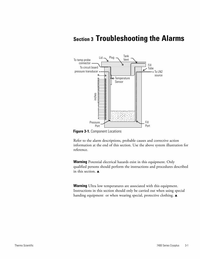
Byp
ass
Sen
sor
and
Op
enV
alve
war
nin
g la
mp
s fl
ash
an
d t
he
alar
m b
ars
ligh
t.T
he
aud
ible
alar
m s
oun
ds.
Fil
l an
d B
ypas
s va
lves
clo
se.
Rem
ote
alar
m c
onta
cts
set
to
acti
vate
in
30 m
inu
tes.
Pri
nte
r p
rin
ts E
rror
Cod
e 9.
Byp
ass
Sen
sor
and
Op
enV
alve
war
nin
g la
mp
s an
d t
he
alar
m b
ars
ligh
t. A
ud
ible
ala
rm s
oun
ds.
Fil
l an
d B
ypas
s va
lves
clo
se.
Rem
ote
alar
m c
onta
cts
acti
vate
imm
edia
tely
.
Pri
nte
r p
rin
ts E
rror
Cod
e 9.
Fil
l co
mm
and
has
bee
n
issu
ed b
y th
e m
icro
pro
cess
or,
bu
t th
e sy
stem
sen
ses
a fa
ilu
re
in t
he
byp
ass
circ
uit
.
Dir
t or
ice
in
th
e fi
ll v
alve
.
Tu
rn o
ff t
he
un
it f
or 1
0 t
o 15 m
inu
tes,
th
en t
urn
it
bac
k on
. If
th
e al
arm
sta
te r
ecu
rs, ca
llT
ech
nic
al
Serv
ices
Dep
artm
ent.
If liq
uid
nit
roge
n r
un
s ou
t of
th
e byp
ass
valv
e,
shu
t of
f th
e L
N2 s
up
ply
sou
rce,
th
en r
emov
e an
d
refu
rbis
h o
r re
pla
ce t
he
fill v
alve
.
9 9
alar
m4a
.cdr
Leve
l
Sen
sor
Leve
l
Sen
sor
Fill
Valv
e
Fill
Valv
e
Byp
ass
Valv
e
Byp
ass
Valv
e
Ope
n
Valv
e
Op
en
Valv
e
Byp
ass
Sen
sor
Byp
ass
Sen
sor
LN
Sou
rce
LN
Sou
rce2 2
Sil
en
ce
Fron
t Pa
nel A
larm
Ala
rm D
esc
rip
tio
n
an
d
Prob
able
Cau
seS
yste
m R
espo
nse
Prin
ter
Erro
r
Cod
eC
orre
ctiv
e A
ctio
n
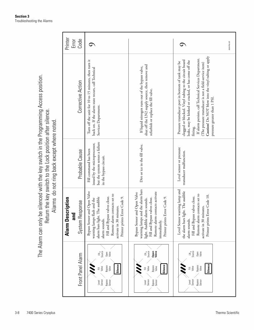
The
Ala
rm c
an o
nly
be s
ilenc
ed w
ith
the
key
swit
ch in
the
Pro
gram
min
g A
cces
s po
siti
on.
Ret
urn
the
key
swit
ch t
o th
e Lo
ck p
osit
ion
afte
r si
lenc
e.
Ala
rms
do
not
ring
bac
k ex
cept
whe
re n
oted
.
Leve
l
Sen
sor
Fill
Valv
e
Byp
ass
Valv
e
Ope
n
Valv
e
Byp
ass
Sen
sor
LN
Sou
rce2
Lev
el S
enso
r w
arn
ing
lam
p a
nd
the
alar
m b
ars
ligh
t.T
he
aud
ible
alar
m s
oun
ds.
Fil
l an
d B
ypas
s va
lves
clo
se.
Rem
ote
alar
m c
onta
cts
set
to
acti
vate
in
30 m
inu
tes.
Pri
nte
r p
rin
ts E
rror
Cod
e 10.
Lev
el s
enso
r or
pre
ssu
re
tran
sdu
cer
mal
fun
ctio
n.
Pre
ssu
re t
ran
sdu
cer
por
t in
bot
tom
of
tan
k m
ay b
e
clog
ged
or
blo
cked
.Vin
yl t
ubin
g to
th
e ci
rcu
it b
oard
leak
s, m
ay b
e ki
nke
d o
r cr
acke
d, or
has
com
e of
f th
e
fitt
ing.
If a
larm
per
sist
s, c
allT
ech
nic
al S
ervi
ces
Dep
artm
ent.
(Th
e p
ress
ure
tra
nsd
uce
r is
not
a f
ield
-ser
vice
ite
m)
Do
NO
T b
low
in
to t
he
vin
yl t
ubin
g or
ap
ply
pre
ssu
re g
reat
er t
han
1 P
SI.
Cau
tio
n!
Sil
en
ce
Sil
en
ce

7400 Series Cryoplus 3-9Thermo Scientific
Section 3Troubleshooting the Alarms
Hig
h t
emp
erat
ure
ala
rm:
Th
e al
arm
bar
s li
ght
and
th
e
tem
per
atu
re d
isp
lay
flas
hes
th
e
ther
moc
oup
le t
emp
erat
ure
.Th
e
aud
ible
ala
rm s
oun
ds.
Rem
ote
alar
m c
onta
cts
set
to
acti
vate
in
30 m
inu
tes.
Ala
rm s
yste
m r
eset
s if
con
dit
ion
corr
ects
.
Pri
nte
r p
rin
ts E
rror
Cod
e 11.
Th
e th
erm
ocou
ple
tem
per
atu
re i
s w
arm
er t
han
the
hig
h t
emp
erat
ure
setp
oin
t.
Th
e li
d h
as b
een
op
en t
oo
lon
g.
An
exc
essi
ve h
eat
load
(war
m p
rod
uct
) h
as b
een
pla
ced
in
to t
he
cham
ber
.
Mak
esu
reth
ete
mpe
ratu
resle
eve
ispr
oper
lyin
stal
led
tolo
wer
the
cham
bert
empe
ratu
re.
Rai
seth
ehi
ghte
mpe
ratu
rese
tpoi
nt.
The
tem
pera
ture
ism
easu
red
usin
ga
T-t
ype
ther
moc
oupl
ew
ithan
accu
racy
of±3
Cfo
r196
C.T
he
tem
pera
ture
grad
ient
with
inth
eta
nkis
depe
nden
tupo
n
chan
gest
oth
eL
N2
whi
chaf
fect
sit’s
stab
iliza
tion
(fill
,
evap
orat
ion,
intr
oduc
tion
ofw
arm
erpr
oduc
t,et
c.).
The
high
erth
ele
velo
fLN
,the
cold
erth
eun
itw
illbe
.Mak
e
sure
the
high
tem
pera
ture
alar
mse
tpoi
ntis
notl
ower
than
the
heig
htof
the
LN
isca
pabl
eof
mai
ntai
ning
.
2
2
11
ala
rm5a.c
dr
Leve
l
Se
nso
r
Fill
Va
lve
Byp
ass
Va
lve
Op
en
Va
lve
Byp
ass
Se
nso
r
LN
So
urc
e2
Sil
en
ce
Te
mp
era
ture
C
o
(Ch
am
be
r te
mp
era
ture
dis
pla
y f
lash
es)
and
Th
e A
larm
ca
n o
nly
be
sil
en
ce
d w
ith
th
e k
ey
swit
ch
in
th
e P
rog
ram
min
g A
cc
ess
po
siti
on
.
Re
turn
th
e k
ey
swit
ch
to
th
e L
oc
k p
osi
tio
n a
fte
r si
len
ce
.
Ala
rms
do
no
t ri
ng
ba
ck
ex
ce
pt
wh
ere
no
ted
.
Leve
l
Se
nso
r
Fill
Va
lve
Byp
ass
Va
lve
Op
en
Va
lve
Byp
ass
Se
nso
r
LN
So
urc
e2
Sil
en
ce
e
tem
per
atu
re d
isp
lay
flas
hes
.h
e
dis
pla
y sh
ows
+199.T
he
aud
ible
alar
m s
oun
ds.
Rem
ote
alar
m c
onta
cts
set
to
acti
vate
in
30 m
inu
tes.
Ala
rm s
yste
m r
eset
s if
con
dit
ion
corr
ects
.
Pri
nte
r p
rin
ts E
rror
Cod
e 12.
Th
e al
arm
bar
s li
ght
and
th T
Tem
per
atu
re p
robe
wir
es
cut
or b
roke
n.
Th
eT
emp
erat
ure
pro
be
con
nec
tor
is u
np
lugg
ed f
rom
the
circ
uit
boa
rd. (F
igu
re 3
-2)
Pro
be
circ
uit
fai
lure
.
Rep
lace
or
rep
air
the
tem
per
atu
re p
robe
wir
es.
Ver
ify
the
circ
uit
boa
rd c
onn
ecto
r.12
Te
mp
era
ture
C
o
+19
9
and
Leve
l
Se
nso
r
Fill
Va
lve
Byp
ass
Va
lve
Op
en
Va
lve
Byp
ass
Se
nso
r
LN
So
urc
e2
Sil
en
ce
Lev
el S
enso
r w
arn
ing
lam
p
flas
hes
an
d t
he
alar
m b
ars
ligh
t.
Th
e au
dib
le a
larm
sou
nd
s.
Fil
l an
d B
ypas
s va
lves
clo
se.
Rem
ote
alar
m c
onta
cts
set
to
acti
vate
in
30 m
inu
tes.
Pri
nte
r p
rin
ts E
rror
Cod
e 10.
Lev
el s
enso
r or
pre
ssu
re
tran
sdu
cer
out
of c
alib
rati
on.
Pre
ssure
tran
sduce
rpor
tin
bott
omof
tan
km
aybe
clog
ged
orbl
ocke
d.V
inyl
tubi
ng
toth
eci
rcuit
boar
d
may
leak
,be
kin
ked
orcr
acke
d,o
rh
asbe
com
e
dis
con
nec
ted
from
the
fitt
ing.
Ifal
arm
per
sist
s,ca
llT
ech
nic
alSe
rvic
esD
epar
tmen
t.
(Th
epre
ssure
tran
sduce
ris
not
afi
eld-s
ervi
ceit
em.)
Do
NO
Tbl
owin
toth
evi
nyl
tubi
ng
or
apply
pre
ssure
grea
ter
than
1P
SI.
Cau
tion
!
Fro
nt
Pa
ne
lA
larm
Ala
rm D
esc
rip
tio
n /
Sys
tem
Re
spo
nse
Pro
ba
ble
Ca
use
Pri
nte
r
Err
or
Co
de
Co
rre
cti
ve A
cti
on
10

3-10 7400 Series Cryoplus Thermo Scientific
Section 3Troubleshooting the Alarms
Leve
l
Se
nso
r
Fill
Va
lve
Byp
ass
Va
lve
Op
en
Va
lve
Byp
ass
Se
nso
r
LN
So
urc
e2
Sil
en
ce
Byp
ass
Sen
sor
war
nin
g la
mp
and
th
e al
arm
bar
s li
ght.
Th
e
aud
ible
ala
rm s
oun
ds.
Th
e R
emot
e al
arm
con
tact
s
set
to a
ctiv
ate
in 3
0 m
inu
tes.
Th
e A
larm
sys
tem
res
ets
if
the
con
dit
ion
cor
rect
s.
Wh
en t
he
syst
em r
ecog
niz
es a
byp
ass
circ
uit
fai
lure
, it
wil
l n
ot
open
th
e B
ypas
sV
alve
an
d
con
tin
ue
the
fill w
ith
out
the
byp
ass
acti
ve.
Th
e sy
stem
doe
s n
ot
det
ect
that
th
e se
nso
r is
con
nec
ted
or
oper
atin
g.
Wir
es m
ay b
e cu
t or
bro
ken
.
Th
e el
ectr
ical
con
nec
tor
may
be
un
plu
gged
fro
m t
he
circ
uit
boa
rd (
Fig
ure
3-2
).
Ch
eck
all w
irin
g fo
r cu
ts o
r bre
aks.
Ver
ify
that
th
e se
nso
r co
nn
ecto
r is
sec
ure
on
th
e
circ
uit
boa
rd (
Fig
ure
3-2
).
Th
e al
arm
is
clea
red
by
turn
ing
the
key
swit
ch t
o
Fu
ll A
cces
s an
d b
ack
to L
ock.
Th
e sy
stem
wil
l go
into
th
e al
arm
sta
te t
he
nex
t ti
me
an L
N2 f
ill
com
man
d i
s is
sued
if
the
byp
ass
fau
lt i
s n
ot
corr
ecte
d.
If t
he
alar
m s
tate
can
not
be
corr
ecte
d, ca
ll t
he
Tec
hn
ical
Ser
vice
s D
epar
tmen
t.
13
ala
rm2a.c
dr
Fro
nt
Pa
ne
l A
larm
Ala
rm D
esc
rip
tio
n
an
d
Pro
ba
ble
Ca
use
Sys
tem
Re
spo
nse
Pri
nte
r
Err
or
Co
de
Co
rre
cti
ve A
cti
on
Th
e a
ud
ible
ala
rm c
an
on
ly b
e s
ile
nc
ed
wit
h t
he
ke
y sw
itc
h i
n t
he
Pro
gra
mm
ing
Ac
ce
ss p
osi
tio
n.
Re
turn
th
e k
ey
swit
ch
to
th
e L
oc
k p
osi
tio
n a
fte
r si
len
ce
.
Ala
rms
do
no
t ri
ng
ba
ck
ex
ce
pt
wh
ere
no
ted
.
Leve
l
Se
nso
r
Fill
Va
lve
Byp
ass
Va
lve
Op
en
Va
lve
Byp
ass
Se
nso
r
LN
So
urc
e2
Sil
en
ce
All w
arn
ing
lam
ps
ligh
t.
Syst
em w
ill n
ot o
per
ate.
Pri
nte
r p
rin
ts E
rror
Cod
e 14.
Th
e m
icro
pro
cess
or s
ees
a ci
rcu
it b
oard
fau
lt o
n
init
ial p
ower
up
an
d t
he
sum
ch
eck
is w
ron
g.
Tu
rn t
he
syst
em o
ff f
or f
ive
to t
en m
inu
tes,
th
en
turn
it
bac
k on
.T
he
syst
em s
hou
ld r
eset
by
rest
orin
g d
efau
lt lim
its.
If s
yste
m d
oes
not
sel
f-co
rrec
t, c
all th
eT
ech
nic
al
Serv
ices
Dep
artm
ent.
14

7400 Series Cryoplus 3-11Thermo Scientific
Section 3Troubleshooting the Alarms
Th
e li
qu
id n
itro
gen
lev
el i
s on
e
inch
or
mor
e ab
ove
the
hig
h lev
el
set
poi
nt.
Th
e re
mot
e co
nta
cts
set
to
acti
vate
in
30
min
ute
s.
Th
e al
arm
sys
tem
res
ets
if t
he
alar
m c
ond
itio
n c
orre
cts.
Pri
nte
r p
rin
ts E
rror
15.
Th
e li
qu
id n
itro
gen
lev
el i
s
one
inch
or
mor
e ab
ove
the
hig
h lev
el s
et p
oin
t.
Mov
e th
e h
igh
lev
el s
et-p
oin
t to
th
e cu
rren
t L
N le
vel.
(Th
e se
t-p
oin
t ca
n b
e ch
ange
d b
ack
aft
er t
he
LN
h
as
evap
orat
ed t
o th
e d
esir
ed lev
el.)
2 215
alar
m6a
.cdr
Fron
t Pa
nel A
larm
Ala
rm D
esc
rip
tio
n
an
d
Prob
able
Cau
seS
yste
m R
espo
nse
Prin
ter
Erro
r
Cod
eC
orre
ctiv
e A
ctio
n
The
Ala
rm c
an o
nly
be s
ilenc
ed w
ith
the
key
sw
itch
in t
he P
rogr
amm
ing
Acc
ess
posi
tion
.
Ret
urn
the
key
swit
ch t
o th
e Lo
ck p
osit
ion
afte
r si
lenc
e.
Ala
rms
do
not
ring
bac
k ex
cept
whe
re n
oted
.
gree
n
gree
n
flas
hing
oran
ge
red
red
high
leve
l
setp
oint
low
leve
l
setp
oint


7400 Series Cryoplus 4-1Thermo Scientific
Section 4 Maintenance
Valve maintenance is described below.
Warning These procedures must be performed by qualified servicetechnicians. s
OperationNormally closed: Valve is closed when solenoid is de-energized, valve isopen when solenoid is energized.
Positioning/MountingThe valve is designed to perform properly when mounted in any posi-tion. However, for optimum life and performance, the solenoid shouldbe mounted upright to reduce the possibility of foreign matter accumu-lating in the core tube area.
Maintenance
Warning Turn OFF electrical power supply and de-pressurize valve beforemaking repairs. It is not necessary to remove valve from pipe line forrepairs. s
CleaningA periodic cleaning of all solenoid valves(s) is desirable. The timebetween cleanings will vary, depending upon media and service condi-tions. Generally, if the voltage to the coil is correct, sluggish valve opera-tion, excessive noise, or leakage will indicate that cleaning is required.
Valve Disassembly and ReassemblyDe-pressurize valve and turn OFF electrical power supply. Proceed inthe following manner:
1. Remove retaining clip and slide entire solenoid enclosure fromsolenoid base sub-assembly.
Caution When metal retaining clip disengages, it springs upward. s
2. Unscrew solenoid base sub-assembly and remove body gasket, coreassembly with rider ring and core spring attached.

4-2 7400 Series Cryoplus Thermo Scientific
Section 4Maintenance
3. Clean and assemble in reverse order of disassembly, paying carefulattention to exploded view provided (Figure 4-1) for identificationand placement of parts.
Note Use thread sealant, not Teflon tape. Tape could get into valve. s
4. After maintenance, operate the valve a few times to ensure properopening and closing.
Protective clothing and gloves should be worn whenever cleaning theinside of this unit. Follow established laboratory procedures. Allow theinterior of the unit to warm to ambient and use an appropriate germicide.
Freezing chamberThe interior of the CryoPlus unit is made of high quality stainless steeland should not be cleaned with any cleanser containing chlorine.
Exterior cabinetWash the outside of the cabinet with a mild detergent.
Figure 4-1. Exploded View of Valve
Housing
Spring Washer
Coil
Solenoid Base Sub-assembly
Core Assembly with Rider Ring
Core Spring
Body Gasket
Valve Body
General Cleaning
Valve Seat

To defrost the storage tank, remove the product and LN2 from the tank.Allow the tank to warm at room temperature.
Caution Do not attempt to speed up LN2 evaporation, or frost removal, byblowing direct heat. Avoid using a heater or blowing compressed air intothe storage tank. s
To defrost the vent port, open the lid and allow to warm at roomtemperature. See Caution above.
The opening of the storage container can be loosely covered while the ventport thaws.
After the port has thawed, remove all moisture from the vent port areabefore returning the tank to service.
The gas springs should be checked periodically, and ideally every sixmonths. The opening force, as measured from the front lip from a closedposition, should be below 100 N (22.5 lbf) maximum. If the force is abovethis value, the gas springs should be replaced. If a force measurement isnot possible, the gas springs should be replaced every two years.
7400 Series Cryoplus 4-3Thermo Scientific
Section 4Maintenance
Defrosting theStorage Tank
Defrosting the VentPort
Gas Springs


7400 Series Cryoplus 5-1Thermo Scientific
Section 5 Specifications
Series CryoPlus 1 CryoPlus 2 CryoPlus 3 CryoPlus 4
LN2 capacity (liters) 90 200 340 552
Static evaporation rate (liters/day)* 3 5 8 10
Static Holding Time (days) 30 40 42.5 55
Exterior Height 41.0" (104.1 cm) 41.0" (104.1 cm) 41.0" (104.1 cm) 47.0" (119.4 cm)***
Exterior W x D 21.5"W x 26.0" F-B** 28.5"W x 34.0" F-B** 34.5"W x 41.5" F-B** 43.5"W x 50.0" F-B**
(54.6 cm x 66.0 cm) (72.4 cm x 86.4 cm) (87.6 cm x 105.4 cm) (110.5 cm x 127.0 cm)
Usable Interior Height 27.5" (69.9 cm) 27.5" (69.9 cm) 27.5" (69.9 cm) 29.5" (74.9 cm)
Usable Interior Diameter 16.0" (40.6 cm) 24.0" (61.0 cm) 31.0" (78.7 cm) 39.5" (100.3 cm)
Electrical 100 - 120 VAC, 1 PH, 50/60 Hz, 0.8 FLA (Operating Range 90-132V)
200 - 230 VAC, 1 PH, 50/60 Hz, 0.5 FLA (Operating Range 180-253V)
Utility Connections 1/2" 45° Flare 1/2" 45° Flare 1/2" 45° Flare 1/2" 45° Flare
4-foot hose 6-foot hose 6-foot hose 6-foot hose
Weight Empty 194.0 lbs. (88.0 kg) 325.0 lbs. (147.4 kg) 416.0 lbs. (188.7 kg) 680.0 lbs. (308.4 kg)
Weight Full 354.0 lbs.(160.6 kg) 680.0 lbs. (308.4 kg) 1021.0 lbs.(463.1 kg) 1620.0 lbs. (734.8 kg)
Shipping Weight 260.0 lbs. (117.9 kg) 400.0 lbs. (181.4 kg) 540.0 lbs. (244.9 kg) 892.0 lbs. (404.6 kg)
Continuing research and improvements may result in specification changes at any time.* Static evaporation rates are based on new container performance, no product load, styrofoam plug/lid, and no lid openings. Actual working performance mayvary with individual applications, ambient conditions, and/or scale accuracy; excludes supply tank evaporation.
** Add 5.0" (12.7 cm) for utilities and lid opening
*** 93.5" (237.5 cm) total unit height of CryoPlus 4 with lid open
Table 5-1. Specifications


Section 6 Parts List
7400 Series Cryoplus 6-1Thermo Scientific
Table 6-1. Parts List
Models
Stock No. Description 7400/7401 7402/7403 7404/7405 7406/7407
103067 Tank trim gasket 5-foot 7-foot 8.5-foot 11-foot
107406 Lid seal gasket 5-foot 7-foot 8.5-foot 11-foot
120054 Dual wheel caster 4 4 4
120059 Caster 4
122010 Lid tumbler lock 1 1 1 1
129063 Lid pneumatic spring 1
129064 Lid pneumatic spring 2
129065 Lid pneumatic spring 2
129066 Lid pneumatic spring (210 lbs.) 2
190526 CryoPlus microprocessor board 1 1 1 1
195000 Ribbon cable - level to main 1 1 1 1
195721 Ribbon cable - control board to main 1 1 1 1
195002 CryoPlus main wiring harness 1 1 1 1
195007 CryoPlus temperature probe 1 1 1
195214 CryoPlus temperature probe 1
195024 120V valve assy. 7400,7402, 7404, 7406 1 1 1 1
195025 220V valve assy. 7401,7403, 7405, 7407 1 1 1 1
400142 RJ-11 output cable 1 1 1 1
195027 CryoPlus control panel assembly 1 1 1 1
195028 CryoPlus level panel assembly 1 1 1 1

6-2 7400 Series Cryoplus Thermo Scientific
Section 6Parts List
Table 6-1. Parts List (continued)
Models
Stock No. Description 7400/7401 7402/7403 7404/7405 7406/7407
251008 Pressure relief valve 1/4" MPT 1 1 1 1
990027 Magnetic lid gasket 1
990028 Magnetic lid gasket 1
990029 Magnetic lid gasket 1
990031 Magnetic lid gasket 1
180143 LN2 dip measuring ruler 1 1 1 1
4000400 4 foot transfer hose 1
4000401 6 foot transfer hose 1 1 1
195884 Lid closing strap 1 1 1 1
123037 Lid magnet 1 1 1 1
4000412 T/C Probe Tubing Replacement Kit (12”) 1 1 1
4000413 T/C Probe Tubing Replacement Kit (15”) 1
400142 RJ-11 Cable 1

7400 Series Cryoplus 7-1Thermo Scientific
Section 7Electrical Schematics

7-2 7400 Series Cryoplus Thermo Scientific
Section 7Electrical Schematics

7400 Series Cryoplus 7-3Thermo Scientific
Section 7Electrical Schematics

7-4 7400 Series Cryoplus Thermo Scientific
Section 7Electrical Schematics

7400 Series Cryoplus 8-1Thermo Scientific
Section 8Warranty Information
TH
ER
MO
FIS
HE
R S
CIE
NT
IFIC
STA
ND
AR
D P
RO
DU
CT
WA
RR
AN
TY
(LN
2V
acu
um
)T
he W
arr
anty
Period s
tart
s t
wo w
eeks f
rom
the d
ate
your
equip
ment
is s
hip
ped f
rom
our
facili
ty.
This
allo
ws f
or
ship
pin
g
tim
e s
o t
he w
arr
anty
will
go i
nto
effect
at
appro
xim
ate
ly t
he s
am
e t
ime y
our
equip
ment
is d
eliv
ere
d.
The w
arr
anty
pro
tec-
tion e
xte
nds t
o a
ny s
ubsequent
ow
ner
during t
he f
irst
year
warr
anty
period.
During the first year, c
om
ponent part
s p
roven to b
e n
on-c
onfo
rmin
g in m
ate
rials
or
work
manship
will
be r
epaired o
r re
pla
ced
at
Therm
o's
expense,
labor
inclu
ded.
LN2
Vacu
um I
nteg
rity
is c
over
ed f
or t
wo
year
s.In
sta
llation a
nd c
alib
ration a
re n
ot
covere
d b
y this
warr
anty
agre
em
ent. T
he T
echnic
al S
erv
ices D
epart
ment m
ust be c
onta
cte
d for
warr
anty
dete
rmin
ation a
nd
direction p
rior
to p
erf
orm
ance o
f any r
epairs.
Expendable
ite
ms,
gla
ss,
filters
and g
askets
are
exclu
ded f
rom
this
warr
anty
.
Repla
cem
ent
or
repair o
f com
ponents
part
s o
r equip
ment
under
this
warr
anty
shall
not
exte
nd t
he w
arr
anty
to e
ither
the
equip
ment or
to the c
om
ponent part
beyond the o
rigin
al w
arr
anty
period. T
he T
echnic
al S
erv
ices D
epart
ment m
ust giv
e p
rior
appro
val
for
retu
rn o
f any c
om
ponents
or
equip
ment. A
t T
herm
o's
option,
all
non-c
onfo
rmin
g p
art
s m
ust
be r
etu
rned t
o
Therm
o p
osta
ge p
aid
and r
epla
cem
ent
part
s a
re s
hip
ped F
OB
destination.
TH
IS W
AR
RA
NT
Y I
S E
XC
LU
SIV
E A
ND
IN
LIE
U O
F A
LL
OT
HE
R W
AR
RA
NT
IES
, W
HE
TH
ER
WR
ITT
EN
, O
RA
L O
R
IMP
LIE
D.
NO
WA
RR
AN
TIE
S O
F M
ER
CH
AN
TA
BIL
ITY
OR
FIT
NE
SS
FO
R A
PA
RT
ICU
LA
R P
UR
PO
SE
SH
AL
L A
PP
LY
.
Therm
o s
hall
not
be lia
ble
for
any indirect
or
consequential dam
ages inclu
din
g,
without
limitation,
dam
ages r
ela
ting t
o lost
pro
fits
or
loss o
f pro
ducts
.
Your
local
Therm
o S
ale
s O
ffic
e i
s r
eady t
o h
elp
with c
om
pre
hensiv
e s
ite p
repara
tion i
nfo
rmation b
efo
re y
our
equip
ment
arr
ives.
Printe
d instr
uction m
anuals
care
fully
deta
il equip
ment
insta
llation,
opera
tion a
nd p
reventive m
ain
tenance.
If e
quip
ment
serv
ice
is r
equired,
ple
ase c
all
your
Technic
al S
erv
ices D
epart
ment
at
1-8
00-4
38-4
851 (
US
A a
nd C
anada)
or
1-7
40-3
73-4
763.
We're re
ady to
answ
er
your
questions on equip
ment
warr
anty
, opera
tion,
main
tenance,
serv
ice and
specia
l applic
ation.
Outs
ide t
he U
SA
, conta
ct
your
local dis
trib
uto
r fo
r w
arr
anty
info
rmation.
Rev.
4
4/0
9
ISO
9001
REGI
STER
ED

8-2 7400 Series Cryoplus Thermo Scientific
Section 8Warranty Information
TH
ER
MO
FIS
HE
R S
CIE
NT
IFIC
IN
TE
RN
AT
ION
AL
DE
AL
ER
WA
RR
AN
TY
The W
arr
anty
Period s
tart
s t
wo m
onth
s f
rom
the d
ate
your
equip
ment
is s
hip
ped f
rom
our
facili
ty.
This
allo
ws f
or
ship
pin
g
tim
e s
o t
he w
arr
anty
will
go into
effect
at
appro
xim
ate
ly t
he s
am
e t
ime y
our
equip
ment
is d
eliv
ere
d.
The w
arr
anty
pro
tec-
tion e
xte
nds t
o a
ny s
ubsequent
ow
ner
during t
he f
irst
year
warr
anty
period.
Deale
rs w
ho s
tock o
ur
equip
ment
are
allo
wed
an a
dditio
nal six
month
s for
deliv
ery
and insta
llation, pro
vid
ed the w
arr
anty
card
is c
om
ple
ted a
nd r
etu
rned to the T
echnic
al
Serv
ices D
epart
ment.
During the first year,
com
ponent part
s p
roven to b
e n
on-c
onfo
rmin
g in
mate
rials
or
work
manship
will
be r
epaired o
r re
pla
ced
at T
herm
o's
expense, la
bor
exclu
ded. In
sta
llation a
nd c
alib
ration a
re n
ot covere
d b
y this
warr
anty
agre
em
ent. T
he T
echnic
al
Serv
ices D
epart
ment
must
be c
onta
cte
d f
or
warr
anty
dete
rmin
ation a
nd d
irection p
rior
to p
erf
orm
ance o
f any r
epairs.
Expendable
ite
ms,
gla
ss,
filters
, re
agents
, tu
bin
g,
and g
askets
are
exclu
ded f
rom
this
warr
anty
.
Repla
cem
ent
or
repair o
f com
ponents
part
s o
r equip
ment
under
this
warr
anty
shall
not
exte
nd t
he w
arr
anty
to e
ither
the
equip
ment or
to the c
om
ponent part
beyond the o
rigin
al w
arr
anty
period. T
he T
echnic
al S
erv
ices D
epart
ment m
ust giv
e p
rior
appro
val
for
retu
rn o
f any c
om
ponents
or
equip
ment. A
t T
herm
o's
option,
all
non-c
onfo
rmin
g p
art
s m
ust
be r
etu
rned t
o
Therm
o p
osta
ge p
aid
and r
epla
cem
ent
part
s a
re s
hip
ped F
OB
destination.
TH
IS W
AR
RA
NT
Y I
S E
XC
LU
SIV
E A
ND
IN
LIE
U O
F A
LL
OT
HE
R W
AR
RA
NT
IES
, W
HE
TH
ER
WR
ITT
EN
, O
RA
L O
R
IMP
LIE
D.
NO
WA
RR
AN
TIE
S O
F M
ER
CH
AN
TA
BIL
ITY
OR
FIT
NE
SS
FO
R A
PA
RT
ICU
LA
R P
UR
PO
SE
SH
AL
L A
PP
LY
.
Therm
o s
hall
not
be lia
ble
for
any indirect
or
consequential dam
ages inclu
din
g,
without
limitation,
dam
ages r
ela
ting t
o lost
pro
fits
or
loss o
f pro
ducts
.
Your
local
Therm
o S
ale
s O
ffic
e i
s r
eady t
o h
elp
with c
om
pre
hensiv
e s
ite p
repara
tion i
nfo
rmation b
efo
re y
our
equip
ment
arr
ives.
Printe
d instr
uction m
anuals
care
fully
deta
il equip
ment
insta
llation,
opera
tion a
nd p
reventive m
ain
tenance.
Conta
ct
your
locald
istr
ibuto
r fo
r w
arr
anty
info
rmation.
We’re r
eady t
o a
nsw
er
your
questions o
n e
quip
ment
warr
anty
, oper-
ation,
main
tenance,
serv
ice a
nd s
pecia
l applic
ation.
Rev.
4
2/0
9
ISO
9001
REGI
STER
ED

7400 Series Cryoplus 9-1Thermo Scientific
Section 9Appendix
Handling Liquid Nitrogen
Warning Contact of liquid nitrogen or cold gas with the skin or eyes maycause serious freezing (frostbite) injury. s
Handle liquid nitrogen carefully. The extremely low temperature can freeze human flesh very rapidly.When spilled on a surface, the liquid tends to cover it completely andintimately, cooling a large area. The gas issuing from the liquid is alsoextremely cold. Delicate tissue, such as that of the eyes, can be damagedby an exposure to the cold gas which would be too brief to affect theskin of the hands or face.
Never allow any unprotected part of your body to touch objects cooled byliquid nitrogen. Such objects may stick fast to the skin and tear the flesh when youattempt to free yourself. Use tongs to withdraw objects immersed in theliquid, and handle the object carefully.
Wear protective clothing. Protect your eyes with a face shield or safety goggles (safety glasses with-out side shields do not give adequate protection). Always wear gloveswhen handling anything that is, or may have been, in immediate contactwith liquid nitrogen. Insulated gloves are recommended, but heavyleather gloves may also be used. The gloves should fit loosely, so thatthey can be thrown off quickly if liquid should splash into them. Whenhandling liquid in open containers, it is advisable to wear high-topshoes. Trousers (which should be cuffless if possible) should be wornoutside the shoes.
Introduction
The safe handling and use of liquid nitrogen in cryogenic refrigerators anddewar flasks is largely a matter of knowing the potential hazards and usingcommon-sense procedures based on that knowledge. There are twoimportant properties of liquid nitrogen that present potential hazards:
1. It is extremely cold. At atmospheric pressure, liquid nitrogen boils at -320° F (-196° C).
2. Very small amounts of liquid vaporize into large amounts of gas. Oneliter of liquid nitrogen becomes 24.6 cu. ft. (0.7 m3) of gas.

9-2 7400 Series Cryoplus Thermo Scientific
Section 9Appendix
The safety precautions in this manual must be followed to avoid potentialinjury or damage which could result from these two characteristics. Do notattempt to handle liquid nitrogen until you read and fully understand thepotential hazards, their consequences, and the related safety precautions.Keep this booklet handy for ready reference and review.
Note Because argon is an inert gas whose physical properties are very similarto those of nitrogen, the precautions and safe practices for the handling anduse of liquid argon are the same as those for liquid nitrogen. s
Use containers designed for low temperature liquids.Cryogenic containers are specifically designed and made of materials thatcan withstand the rapid changes and extreme temperature differencesencountered in working with liquid nitrogen. Even these special contain-ers should be filled SLOWLY to minimize the internal stresses that occurwhen any material is cooled. Excessive internal stresses can damage thecontainer.
Do not cover or plug the entrance opening of any liquid nitrogen refrigera-tor or dewar. Do not use any stopper or other device that would inter-fere with venting of gas. These cryogenic liquid containers are generally designed to operate withlittle or no internal pressure. Inadequate venting can result in excessive gaspressure which could damage or burst the container. Use only the loose-fitting necktube core supplied or one of the approved accessories for clos-ing the necktube. Check the unit periodically to be sure that venting isnot restricted by accumulated ice or frost.
Use proper transfer equipment. Use a phase separator or special filling funnel to prevent splashing andspilling when transferring liquid nitrogen into or from a dewar or refrigera-tor. The top of the funnel should be partly covered to reduce splashing.Use only small, easily-handled dewars for pouring liquid. For the larger,heavier containers, use a cryogenic liquid withdrawal device to transfer liq-uid from one container to another. Be sure to follow instructions suppliedwith the withdrawal device. When liquid cylinders or other large storagecontainers are used for filling, follow the instructions supplied with thoseunits and their accessories.
Do not overfill containers. Filling above the bottom of the necktube (or specified maximum level)can result in overflow and spillage of liquid when the necktube core orcover is placed in the opening.

7400 Series Cryoplus 9-3Thermo Scientific
Section 9Appendix
Never use hollow rods or tubes as dipsticks. When a warm tube is inserted into liquid nitrogen, liquid will spoutfrom the top of the tube due to gasification and rapid expansion of liq-uid inside the tube.
Warning Nitrogen gas can cause suffocation without warning! s
Store and use liquid nitrogen only in a well-ventilated place.As the liquid evaporates, the resulting gas tends to displace the normalair from the area. In closed areas, excessive amounts of nitrogen gasreduce the concentration of oxygen and can result in asphyxiation.Because nitrogen gas is colorless, odorless and tasteless, it cannot bedetected by the human senses and will be breathed as if it were air.Breathing an atmosphere that contains less than 18% oxygen can causedizziness and quickly result in unconsciousness and death.
Note The cloudy vapor that appears when liquid nitrogen is exposed tothe air is condensed moisture; not the gas itself. The issuing gas isinvisible. s
Never dispose of liquid nitrogen in confined areas or places where othersmay enter.Disposal of liquid nitrogen should be done outdoors in a safe place.Pour the liquid slowly on gravel or bare earth where it can evaporatewithout causing damage. Do not pour the liquid on pavement.
If a person seems to become dizzy or loses consciousness while workingwith liquid nitrogen, move to a well-ventilated area immediately. Ifbreathing has stopped, apply artificial respiration. If breathing is difficult,give oxygen. Call a physician. Keep warm and at rest.
If exposed to liquid or cold gas, restore tissue to normal body temperature(98.6°F) as rapidly as possible, followed by protection of the injured tissuefrom further damage and infection.
Remove or loosen clothing that may constrict blood circulation to thefrozen area. Call a physician. Rapid warming of the affected part is bestachieved by using water at 108°F. Under no circumstance should thewater be over 112°F, nor should the frozen part be rubbed either before orafter rewarming. The patient should neither smoke nor drink alcohol.
First Aid


Thermo Fisher Scientific401 Millcreek RoadMarietta, Ohio 45750United States
www.thermofisher.com