Embed Size (px)
Citation preview

Critical Design Review Report:
SpeakerBus
May 13th, 2016
Andrew Coles
Aaron Grace
Jennifer Hu
Sergio Lara
1

Table of Contents
Executive Summary ----------------------------------------------------------------------------------------- 3
Background --------------------------------------------------------------------------------------------------- 4
Problem Analysis -------------------------------------------------------------------------------------------- 6
Design ---------------------------------------------------------------------------------------------------------- 8
Test & Validation -------------------------------------------------------------------------------------------- 11
Data Analysis ------------------------------------------------------------------------------------------------- 14
Problems Encountered ------------------------------------------------------------------------------------- 21
Schedule and Budget ---------------------------------------------------------------------------------------- 22
Risk Analysis ------------------------------------------------------------------------------------------------- 23
Conclusions --------------------------------------------------------------------------------------------------- 24
Appendices ---------------------------------------------------------------------------------------------------- 25
2

Executive Summary
SpeakerBus will provide home theater system users with increased versatility and excellent performance by allowing users to augment existing installations with additional speaker units. The primary objective for SpeakerBus shall be to send power and multiple audio signals along one common pair of shared wires.
The introduction of home theater systems has created a large market for those who seek superior audio quality in their entertainment, whether that be television, movies, or music. With the abundance of quality systems available on the market, one might have trouble deciding which system best fits their individual needs. The majority of home theater systems are very similar to one another in terms of required speaker location and receiver-speaker communication standards. To design a custom surround sound environment at home, a receiver would be purchased and placed centrally, usually underneath the television. A receiver’s purpose is to process audio signals, amplify them, and send them to the individual speakers. Pre-packaged systems are popular, as they allow for simple plug and play operation with a variety of different audio output devices including televisions, cable boxes, game consoles, Blu-ray players, and others. In addition to the receiver, speakers are required to broadcast the content of each audio channel (left, right, high frequency, low frequency, etc.) The composition of each of these channels varies from manufacturer to manufacturer, however, and the consumer is generally locked into one standard once they install their system. In order to reduce clutter in the home environment, the cables that connect each speaker to the receiver are often run through walls and ceilings. This is often the most difficult aspect of installing a home theater system.
To reduce the amount of cables needed for an ideal home theater design, SpeakerBus will provide power to speakers and send a multiplexed signal (containing every channel’s audio signal, multiplexed together) over a common pair of wires. With this reduction of wires (from two wires for each individual speaker to two two for the entire system) needed for the system to operate, SpeakerBus will provide convenience without sacrificing quality to consumers. Our transmitter will receive two analog audio inputs, digitize them, multiplex them together, and transmit this pulse code modulated (PCM) stream along with power over a common pair of wires to each receiver-speaker combination. The receiver will demodulate the digitized signal for the appropriate channel (for example, the right receiver will isolate the right channel’s data) and convert it back to an analog signal to be played through the attached speaker as well as provide power to the speaker.
3

Background
The goal of SpeakerBus is to model a system which can be used to create a standalone system that can be integrated into homes and professional theater applications to expand versatility in any listening environment. The mission is to test and build a system that streams two audio inputs and dc power across a common pair of speaker wires. The receiving end will then output the two audio signals to two separate speakers, with each speaker playing an audio signal that is within 15% error of the original signal.
Current surround sound speaker systems, such as 5.1, 5.2, 7.1, 9.1, and so on, require each speaker to be individually wired to one transmitter. The 5, 7, and 9 refer to the number of normal speakers, while the .1 (or occasionally .2) refers to a subwoofer. The typical arrangement places one speaker directly in the center, with two to four on the left and right of center, and two to four behind the viewer. These arrangements are excellent at providing surround sound for music, television, and films. It can be difficult to install in homes.
Fig. 1: Standard 5.1 layout, with each orange line representing a direct wired path to the transmitter
In the first phase of development spanning the Fall and Spring semesters of the 2015-2016
academic year, SpeakerBus attempted to utilize GNU Radio software, a free, open source toolkit used with software defined radios and maintained by the GNU project. GNU Radio operates on a graphical flowchart input, creating a python file which is then executed by GNU Radio, and drives the software defined radio (SDR).
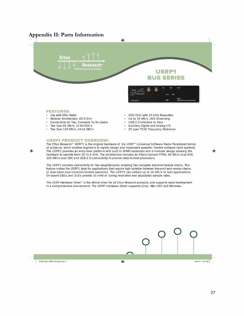
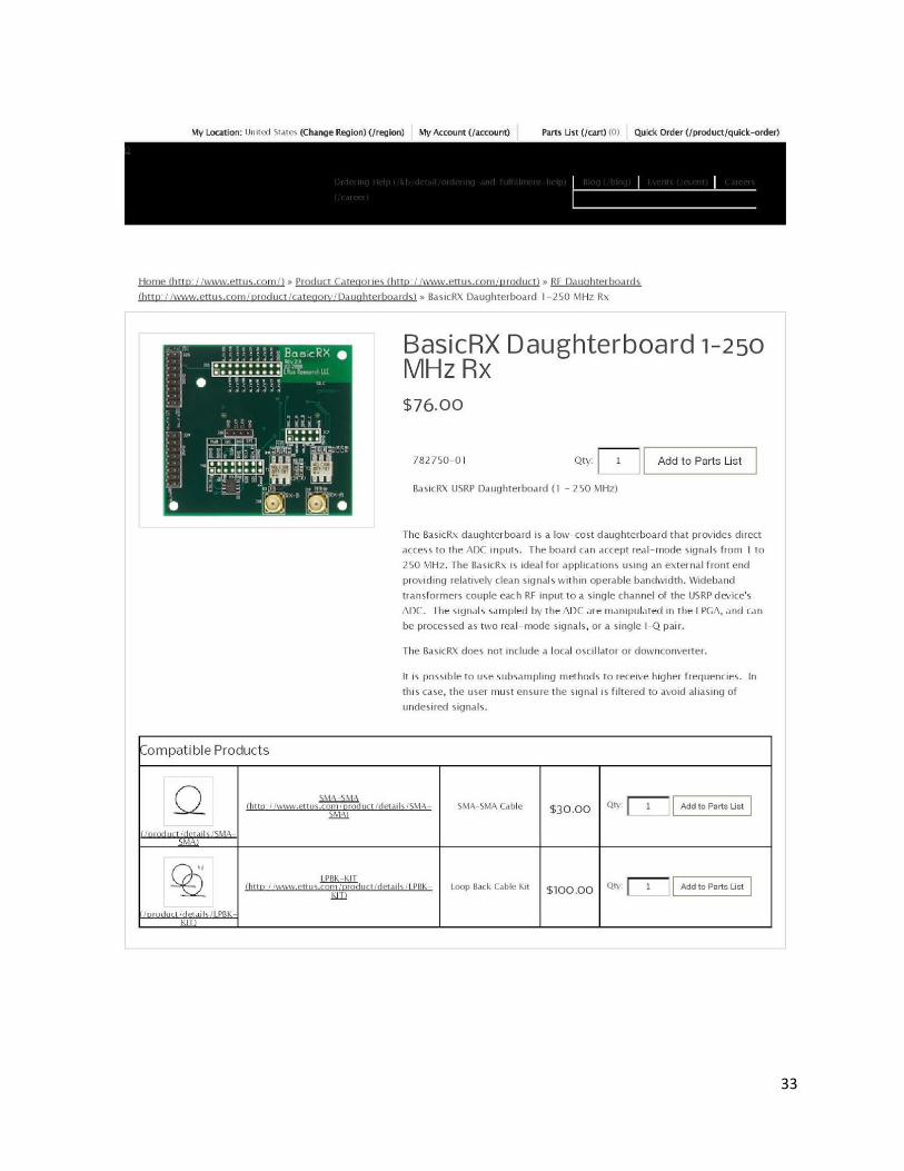
The SDR that was utilized for SpeakerBus is a package acquired from Ettus Research, an SDR development company based in California. SpeakerBus was developed using two USRP1 (Universal Software Radio Peripheral) units, each of which contains a USRP1 motherboard coupled with a LFRX daughterboard, a low frequency receiver, and a LFTX daughterboard, a low frequency transmitter. Detailed information, including data sheets from Ettus Research about the Ettus hardware, can be found in the Appendix.
4

Competing technologies include the broad field of power-line communications (PLC), which uses ac power lines in private homes in order to communicate internet data. In homes where wireless communication via WI-FI is not practical due to building materials, large distances, etc., a PLC transmitter can be plugged in near the modem or power outlets throughout the house. The outlets are equipped with a decoder which removes the ac power from the signal, and outputs the transmitted data.
As a capstone project, this venture is not currently in use and exists primarily as a proof of concept. Proof of concept will primarily be tested and simulated using existing software defined radio technology.
5

Problem Analysis SpeakerBus is based on the use of common, two conductor speaker wire, as pictured below.
Fig. 2: Common speaker bi-wire
The task at hand is to multiplex audio inputs from two sources onto a single pair of wires
along with the requisite power for the two receiver-speaker units. In simple terms, the project involves transmitting two different audio signals and power to two separate dc powered speakers with one common pair of wire connecting all components. Throughout the duration of the first phase of development, the project will be demonstrated using software defined radio software and hardware that will digitize two analog audio inputs, and modulate the two digital audio signals and 2.5W (5V, 500mA) of dc power, and transmit the resultant digital signal across a common pair of wires to the receiving end of another SDR unit and outputted to two sets of two dc powered speakers (four total).
The primary objective of this project is to utilize one pair of speaker wires in order to transmit two audio streams to two speakers (along with utilizing the available SDR technologies.) A secondary goal, outside of the scope of the original capstone, which is accomplishable using the technological basis being developed, is to use available speaker wires in order to extend existing sound installations to include more speakers. SpeakerBus will allow for the maximization of existing connections such that the sound system is optimized for a given home. For example, SpeakerBus could be used to extend the spectral range of a given set of speakers by augmenting an existing speaker installation with additional high or low frequency speakers. This creates a sonic environment wherein there is an improved range of frequency being played from all angles.
The existing wires in place in houses could be used better. It is possible to utilize existing audio system components (speakers, speaker wires, etc.) such that transmission of CD quality music becomes trivial, no matter what the physical location of the speakers is, as long as the newly installed speakers are relatively close to existing installed speakers.
6

Fig. 3: Augmenting existing speaker installation using SpeakerBus’s receiver-speaker combination
7

Design
The basic design of the project consists of one transmitter and two receiver-speaker pairs.
The transmitter will transmit multiple signals along a common pair of wire along with dc voltage to power up the receiver and the speakers, respectively. The receivers will demodulate the signals which are then passed to the speakers to be amplified and played back.
Fig. 4: System Block diagram
The transmitter will consist of a PC running GNU Radio software connected to a USRP1
motherboard and two LFTX daughterboards which each digitize one of two unique analog inputs and modulate this digital signal using frequency shift keying (FSK). The outputs of the LFTX1 and LFTX2 can be seen above in Fig. 4 in red. After modulation, the two signals will be multiplexed using a combination circuit developed by the original SpeakerBus team. This circuit is pictured in Fig. 5 in more detail.
The breadboarded combination circuit consists of the two inputs from the LFTX1 and LFTX2 (brought onto the breadboard by specially made SMA coaxial to 16 AWG speaker wire to breadboard wire connectors) and two LM324-N op amps (there are four op amps per LM324-N IC package), one in adding configuration and one in inverting configuration. The output from this dual op-amp circuit is dc coupled via capacitor to the dc power supply. The power supply in the original phase is a 12V, 500 mA wall plug (120V adapter) which is regulated using a L78S05CV 12 V to 5 V dc regulator. Using speaker wires soldered to standard breadboard wire, the speaker wire carries the +5 V biased signal across another section of the breadboard where the filtering circuit was modeled.
8

Fig. 5: Combination circuit from Fig. 4
The receivers will consist of a filtering circuit as seen in
Fig. 4 which will separate the signal into its ac and dc constituents. This is accomplished with simple, RC filters, one high pass and one low pass. They were designed with a 45 kHz cutoff frequency in mind. The circuit diagram can be seen in Fig. 6 to the right. Note that there is a capacitor between V2 in Fig. 5 and V3 in Fig. 6. The output from Vl will provide dc power at 5V, 500mA and the output from Vh will provide the LFRX1 and LFRX2 with the time-varying signal to be demodulated. Each speaker will play different signals which are received from the PC running GNU Radio connected to the LFRX daughterboards via the USRP1 as in Fig. 4, each daughterboard will be able to retrieve the correct information from the one, multiplexed signal from Vh.
Fig. 6: Receiver Circuit
The design of the software will be discussed more thoroughly in the test and validation
section, as it was never fully completed, but briefly, the designed software was run on two Ubuntu PCs, each of which was running one instance of the open source GNU Radio software. This
9

software was the primary design challenge, and the largest stumbling block in the SpeakerBus project. The individual software block parameters were not configurable to the degree required for successful implementation. Due to the nature of open-source software projects like GNU being primarily developed by hobbyists, students, or other non-professionals, documentation is scarce, generalizability is extremely limited, and individual blocks are not guaranteed or even expected to “play well” with one another. The GNU Radio software package is only one of many available to interface with the Ettus USRP family of SDRs. Some other software packages include those available in MATLAB via Simulink in R2014b as well as LabVIEW.
The transmitter end was most successfully implemented in the following configuration: a sinusoidal signal source was created by the software, modulated using a simple frequency modulation block, (with one parameter in the block, seemingly unrelated to carrier frequency) and transmitted from the LFTX to the LFRX via an SMA coaxial cable connection. The process was monitored in several places with the GNU Radio QT GUI (graphical user interface) Sink, which allowed for monitoring of the signal in both the time and Fourier domain. The receiving software was very similar in design, but reversed. This entailed the USRP source as an input, followed by an FM demodulator coupled to an audio sink and another QT GUI Sink to monitor the results. In a successful implementation of the project, the software would likely be very similar, with FSK modulation blocks in place of the FM modulation blocks of the current test implementation and the microphone as input rather than a sinusoidal source.
10

Test and Validation
The transmitter and the receiver are to be tested independently of each other. Ensuring the success of each subsystem will facilitate the completion of the project by allowing the team to isolate where failure is most likely to occur. Similarly, the hardware-side (analog filtering components) and software-side components (including the Ettus board hardware) shall be tested separately before being coupled together, in order to minimize potential damage to the expensive Ettus hardware. It is vital to ensure that the power being absorbed by the Ettus hardware is within the operational recommendations from the manufacturer.
The transmitters (LFTX1 and LFTX2) shall be tested using an oscilloscope to ensure that the antenna is outputting what the software indicates. The receivers are to be tested in their ability to demultiplex and demodulate the signal by listening to the signal being created in the software. Additionally, the two audio signals being sent to the speakers shall each be tested by using an oscilloscope to measure both the output (to speaker) analog signal and the corresponding input (to transmission PC) analog signal and subtracting the two measurements to ensure the error magnitude is within 15% of the input and output analog signals.
The transmitter is responsible for modulating, multiplexing, and transmitting the signal, along with power, to the receivers. To test the transmitter, a signal will be generated using the GNU Software Defined Radio which will then be digitized. The digital signal is then modulated using the Frequency Modulation block transmitted to the receivers using coaxial cable.
Fig. 7: Frequency modulation (FM) and demodulation simulated with GNU Radio. To test the modulation of the signals, a control signal is created using the Signal Source
block found under the Waveform Generators list in GNU Radio. The signal source block allows users to specify the sampling rate, type of waveform, amplitude, frequency, and offset. The generated signal is then passed to the frequency modulation block found under the Modulation list. The frequency modulation block only has one parameter, “sensitivity” and it is defined as radians per sample over amplitude. It is unclear what this parameter refers to, exactly, due to its ambiguous name and lack of documentation. For this reason, it is seemingly impossible to specify the carrier
11

frequency. Gaussian Frequency Shift Keying (GFSK) was originally the chosen modulation scheme. The GFSK block is not documented and after extensive testing, the modulation block was labeled as non working and was replaced with frequency modulation.
From the modulation block, the signal is passed to the Frequency Demodulation block, found under the Modulation list, to be demodulated. In the demodulation block, the channel rate and the audio decimation parameters have to specified. Channel rate is defined as the sampling of the incoming signal and the audio decimation is defined as an integer decimation rate. From the demodulation block, the resulting signal is passed to QT GUI Sink found under the Instrumentation list. The QT GUI Sink has different scopes which can be used to analyze signals. The FFT spectrum analyzer and the waterfall scope are the most useful.
Fig. 8: FM modulation and transmission implemented with GNU Radio
Transmission of the signals is tested by creating a control signal, modulating the signal, and transmitting the signal to the transmitter boards. To transmit the modulated signal, it must first be interpolated to the sampling rate required by the transmitting board using the rational resampler block found under the resampler list. The resampler block has two parameters, decimation and interpolation. The USRP1 paired with the LFTX boards require a sampling rate of 250,000 samples per second and are able to transmit at carrier frequencies starting at dc to 30 MHz. The generated signal was originally sampled at 50,000 samples per second adding the need for the resampler. The resampler was used to interpolate the signal by 5, increasing the sampling rate to 250,000. From the resampler, the resampled signal is sent to the UHD: USRP Sink found under the UHD list. The UHD:USRP Sink block sends the signal to the LFTX board using the specified parameters. The daughterboard is then connected to an oscilloscope and analyzed.
In the USRP Sink, the center frequency is specified along with the sampling rate. It is worth noting that the block allows user to specify the sampling rate, but upon execution of the flowchart, the USRP1 motherboard will run at 250,000 samples per second regardless of the sampling rate specified. There are two ways to specify the transmission ports on the USRP Sink. The method depends on the type of daughter boards used. For the LFTX, the subdevice specifications is used to define the port. The input to the parameter is a 3 character string where the first letter specifies the slots in the USRP1 where the daughterboard is placed. The first letter is followed by a colon which
12

is then followed by the letter of the port in the daughterboard being used. Other types of daughterboards used the antenna parameter in the USRP sink.
Testing the receiver consist on receiving a modulated signal and demodulating the signal accurately. The signal is received from the LTRX boards using the UHD:USRP Source found under the UHD list. The parameters in the USRP Source block are similar to those in the USRP Sink. The center frequency and sampling rate need to match those in the UHD: USRP Source block in order to receive the signal. The incoming signal is decimated to 50,000 samples per second using the resampler block to decimate by 5. The resampled signal is then demodulated using the frequency demodulation block and send to the audio sink and the QT GUI Sink blocks. The audio blocks allow the signal to be played on speakers connected to the computers using a 3.5 mm auxiliary cable. The demodulated signal is then compared to the generated signal.
Multiple signals can be created, modulated, and transmitted at the same times using different carrier frequencies.
Fig. 9: FM receiving and demodulation implemented with GNU Radio
13

Data Analysis
Fig. 10: Signal generated using the GNU Software Defined Radio: 50 Hz cosine amplitude of 5
Fig. 11: Frequency Spectrum of the original signal
14

Fig. 12: Frequency Spectrum of the GFSK modulated signal.
Fig. 13: Demodulated signal on the transmitter side
15

Fig. 14: Frequency Spectrum of the demodulated signal.
The modulation of the signal is working correctly. A cosine at a frequency of 50 Hz with an
amplitude of 5 was created and modulated. After demodulating the modulated signal, the output was close to the original signal. The frequency spectrum on the demodulated signal had a peak at 50 Hz which represents the frequency of the cosine and from the scope, the amplitude of the demodulated signal was really close to 5, which demonstrated that the signal was demodulated correctly, as can be seen from the amplitude.
Fig. 15: GFSK Modulated input to the receiver
16

Fig. 16: Demodulated signal output
Fig. 17: Frequency spectrum of the demodulated signal.
The demodulation is working correctly. A cosine at a frequency of 50 Hz with amplitude of
5 was modulated and passed to the receiver. The receiver demodulates the input signal and was able to recover the cosine accurately. The frequency spectrum displayed the frequency to be 50 Hz and the scope revealed the amplitude of the cosine signal to be 5, which is really close to the original signal.
17

Fig. 18: Artificial LFTX1 and LFTX2 outputs to test combination circuit
The above, Fig. 18, displays the voltage levels of two sinusoidal signals (100 kHz in blue and
200 kHz in yellow) input to the the analog combination circuit in order to test it for effectiveness. These are simplified versions of what the LFTX outputs would look like, in order to evaluate the combination circuit more effectively.
Fig. 19: Combination of two signals from Fig. 18
The result of the first stage of the op amp circuit (V1 from Fig. 5). This is inverted from the
orientation of the desired, combined signal, due to the negative feedback used in the combination circuit of Fig. 5. This is then un-inverted, as can be seen in the second stage of the combination circuit, and demonstrated successfully by Fig. 20 below.
18

Fig. 20: Adder and inverter output op amp power: ±15V Rf = 22kΩ
Fig. 20 demonstrates the results of the original test from calculations and simulations made
before construction of the combination circuit. The input is in yellow and the output in blue. The values of voltage and resistance found above worked in TopSPICE simulation, but when constructed on the breadboard produced the distorted waveform seen above.
Fig. 21: Adder and inverter output op amp power: ±6V Rf = 300kΩ
Fig. 21, above, demonstrates the results of different voltage values used to power the op amp to combine and invert the multiple inputs. This was a result of increasing the resistance from 22kΩ to 300kΩ in order to decrease the necessary power for the op amp from ±15V to ±6V. In addition to lessening the power requirement (and opening up the option of using a 12V wall power adapter), the signal was far less distorted at its peaks. These are the voltage and resistance values used in the current design.
19

Testing indicates, at the time of the writing of this report, the analog combination and filtering circuits are successful at combining and isolating signals and dc power in the range required. Testing the filtering circuit entailed sending the waveform from Fig. 21, biased by the 5V regulated voltage via DC coupling, through the two RC filters, set to filter above and below 45 kHz for input to the LFRXs and powering the speakers, respectively. The filters successfully removed the high frequency components from the power and vice versa, providing the correct amount of power to the speakers.
Fig. 22: Reflection (top row) and Transmission Loss (bottom row) For 14,16, and 18 AWG cables
Fig. 22, above, represents data taken from a spectrum analyzer testing three different gauges
of speaker wire. The top row represents the reflection against a 50Ω load with each different gauge across a 0 to 30 MHz frequency sweep, while the bottom row represent the data from transmission losses measured in each specific gauge, across the same frequency sweep.
20

Problems Encountered
As stated earlier, the primary problem encountered in SpeakerBus was one of software. The GNU Radio software, like other open-source repositories, is not well maintained, robustly programmed, or well documented. It is likely that many of the blocks that were used were originally developed by hobbyists or students for particular uses, without concern over whether or not they would interface with other blocks or other hardware peripherals than those which were originally used. The next capstone group to work on this project would be served well by attempting to learn Python, the language which GNU Radio uses to run the blocks, in order to write custom blocks for the project, or at least better understand existing blocks.
There was a significant amount of noise introduced into the FM test scenario, despite the fact that the boards were directly wired together. This problem is likely, again, due to software, and so the previous recommendation to devote a large amount of time to the Python code in order to more fully understand the software.
Another manifestation of the pervasive software issue is the somewhat troubling fact that the receiving PC was unable to receive from multiple daughterboards. This is likely due to incorrectly valued parameters, as it is noted on the Ettus website that multiple LFRX boards are able to be used concurrently in one GNU Radio flowchart.
Due to the fact that the combination, dc coupling, and filtering circuits were never tested with actual audio signals, and only oscilloscopes, it is likely that there exists deformation of overall signal integrity. The resistor and capacitor values, along with the choice of op amp, may need to be slightly tweaked in order to permit better signal integrity.
21

Schedule The following table displays the milestones that the SpeakerBus capstone group accomplished in Fall 2015 and Spring 2016.
Milestone Date Completed
Begin project August 28th, 2015
System Critical Review (SCR) September 18th, 2015
Preliminary Design Review (PDR) October 16th, 2015
Completed Simulations November 20th, 2015
Critical Design Review (CDR) December 4th, 2015
Fall Semester Final Report December 11th, 2015
Prototype Completed March 25th, 2016
Video and Poster Completed May 4th, 2016
Intermediate Design Review May 5th, 2016
Final Design Review May 10th, 2016
Final Report May 11th, 2016
Project Completion May 11th, 2016
Budget
Given Budget $1,000.00
Parts $597.19
Misc (Poster, Report Binding) $160.00
Total $757.19
22

Risk Analysis
Receiver Software Transmitter Power Overall
Performance
Schedule
Cost
Safety
Testing
Manpower
Facilities
Overall
In the course of this capstone project, a few risks have developed in each of the subsystems:
receiver, software, transmitter, and power. Due to the limited GNU radio documentation and the learning curve associated with using the GNU Radio software, time was not an ally. Many of the problems encountered in GNU Radio were discussed in the section, Problems Encountered. The time leftover from the initial design was not enough for the software development, which encompassed writing Python code and debugging every block in the GNU radio. Time was the biggest risk that inhibited the group from delivering a functional product. Delaying goals or milestones, as set forth by the schedule, proved harmful to the overall schedule of completion. Most of the project progresses and advancements are based on completing previously set goals.
Since the software was not fully functioning to meet the requirements of the project, the hardware was not able to be fully tested. The hardware and the software aspects of the project were correlated with each other. Therefore, the receiver and transmitters are inhibit the success of the project. Throughout the span of this project, the hardware, software, and power didn’t pose a safety hazard.
This project requires the group members apply knowledge learned both in class and through individual research. Research is key to the success of SpeakerBus. Each subsystem is susceptible to the risk of failure from inadequate. Purchasing incorrect parts was a low risk for each subsystem. This risk was mitigated by reading the data sheets carefully and simulating the system thoroughly. The parts arrived quickly.
The budget is always a risk, but plans to mitigate overspending by allocating a portion of the budget for any unforeseen circumstances have been recorded. For instance, there is a portion of the budget would to be used for damaged components or speakers. The risk will be lessened by buying decently-priced parts, in order to safeguard against receiving poor-quality parts. At the end of the Spring 2016 semester, $757.19 of the allocated budget was spent.
23

Conclusions Due to unforeseen difficulties in using the GNU Radio software with regard to designing
and implementing a working product, the project is incomplete. However, that is not to say that progress was not made towards accomplishing the ultimate goal. The most progress occurred in the design of the analog combination, dc coupling, and filtering components. This aspect of the project was demonstrated to be in working order, and will likely only need minimal changes to accommodate to another capstone group.
It is imperative that new task allocations are designated, in order to design a final product from multiple engineering or computer science foci. Partitioning the load of the final system into one that solves the software problems, and one that focuses especially on reducing interference and noise from the final product, for a SpeakerBus that lives up to its original design specifications of CD quality audio transmitted with power along one set of speaker wires. Ideally, students focusing on individualized and unique challenges could provide for faster solutions and saved time. Once both elements of the project, hardware and software, have been successfully designed, tested, and validated, the integration of the two systems can begin.
The final implementation of SpeakerBus will be able to offer customers the versatility of contemporary audio paradigms like Dolby Atmos at a fraction of the cost. With its ease of integration, customers can design their ideal custom audio experience in the comforts of their own home, and install it quickly and easily.
This project was tremendously educational for all group members involved, in vastly different ways than any other class undertaken in the BSEE program. The ability to work together as a cohesive team is one often taken for granted by students who have not yet participated in a Capstone design class. However, these two semesters have clearly illustrated that not only is it more difficult than it seems on the surface, but also more rewarding. In addition to the interpersonal skills this project has provided, all group members involved have had an opportunity to apply theoretical knowledge learned over the course of their undergraduate degree to real-world problems and been successful to some extent, especially in regards to simulation, construction, and testing of analog circuit components. Being exposed to the problems borne of open source software generally, and GNU Radio specifically has proven to be a very educational experience for all group members, as it has illustrated the importance of asking for and utilizing help whenever available. Group members have spent a large amount of time wrestling with a complex, multi-faceted problem, and learned both about their own abilities and the abilities of their group-mates
24

Appendix I: Parts List
Description Part Number QTY Cost (ea) Shipping
Cost (Total)
LFRX Daughterboard 0-30 MHz Rx 782752-01 3 $76.00 $0.00 $228.00
LFTX Daughterboard 0-30 MHz Tx 782753-01 3 $76.00 $0.00 $228.00 Bullz Audio (BPS14.25PB) PRO Platinum/Blue 25' 14-Gauge Speaker Cable ASIN #: B00NQ8FD1Y 1 $7.26 $0.00 $7.26 Carwires SW1200-15 - 12-AWG High-Strand Car Speaker Wire (15 ft.) ASIN #: B0086NYLZ8 1 $14.99 $0.00 $14.99 Sewell 16-Gauge Speaker Wire, 50 ft ASIN #: B00B4ZNN5O 1 $10.95 $0.00 $10.95
RadioShack 60-ft. Speaker Wire - 18 Gauge ASIN #: B015JNGD7Q 1 $8.19 $0.00 $8.19
12V 1A DC power supply ASIN #: B00452YFZU 2 $5.57 $0.00 $11.14
L78S 12V to 5V regulator 511-L78S05CV 1 $0.67 $0.00 $0.67
DC Powered Speakers ASIN #: B00GHY5F3K 2 $11.99 $0.00 $23.98 Breadboard friendly 2.1mm DC barrel jack B00KLDQ3XO 2 $2.79 $ 3.55 $9.13
25

USB Type A Female Field Termination Connector USBAFT 3 $6.99 $10.95 $31.92 Cable Assembly SMA Male to SMA Male 1 Foot RG-174coax Cable 50 Ohm 163855 5 $4.09 $2.51 $22.96
*All amazon products have an individual ASIN # Total $597.19
26
Appendix II: Parts Information
27

28

29

30

31

32
33

34

35

36

37

38

39

40

41

42

43

44

45

46

47

48

49

50

51

52

53

54

LFTX Daughterboard Schematic
55

LFRX Daughterboard Schematic
56
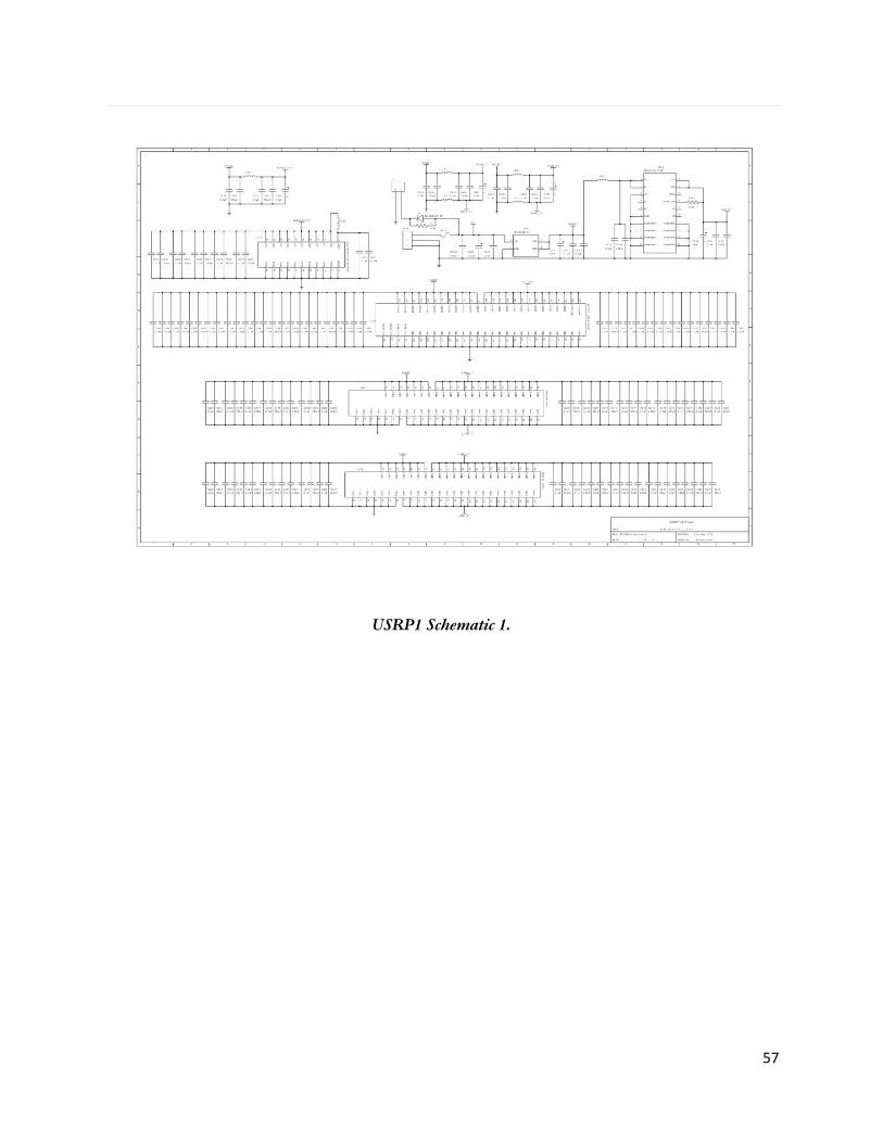
USRP1 Schematic 1.
57

USRP1 Schematic 2.
58

USRP1 Schematic 3.
59

USRP1 Schematic 4.
60