Embed Size (px)
Citation preview
Creating a Desktop Electric Motor Dynamometer System withTI’s C2000 Support Package and Model-Based DesignBy Kerry Grand, MathWorks
With nearly 50% of the world’s electricity consumed by electric motors, more and more companies and universities are researching anddeveloping energy-saving solutions like variable frequency drives (VFDs).
A VFD regulates motor speed and torque by varying motor input frequency, voltages, and currents. It usually consists of an embeddedcontroller, an inverter to convert DC voltage to three-phase AC voltage, and a three-phase motor. The motor typically is a permanentmagnet synchronous machine (PMSM) or an induction machine (IM). For both research and control law development, VFD systemsmust be tested on a dynamometer. A full-power dynamometer is a costly solution. It is, therefore, desirable to use a lower-costdynamometer system that is capable of running at lower DC bus voltage using a current limited supply, reducing safety and systemdamage concerns.
This article describes a workflow using Model-Based Design with MATLAB® and Simulink® to develop a desktop or lab dynamometer.We begin by outlining the hardware and software configuration used to create this closed-loop system, the physical equations governingthe IM, and the underlying control principles. We then describe the main steps in the workflow: developing and simulating the model,converting the control law to embedded target code, testing the motor controller software in speed or torque mode, and deploying thecode on a dynamometer test system.
Design Requirements and System Components
The fundamental goal of our dynamometer system is to provide a safe and low-cost test environment. Requirements include:
▪ The ability to supply a low-voltage (42 V or less) DC power supply for the inverter so as to reduce the energy potential of the DC bus,as well as shock hazards
▪ Safe mechanical housing and fixtures for the IM and DC motors, protecting the operator against coupling failure, unintended torquecommands, or other system failures
▪ Remote control and calibration capabilities
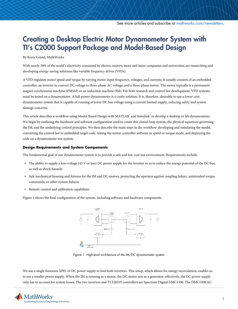
Figure 1 shows the final configuration of the system, including software and hardware components.
Figure 1. High-level architecture of the IM/DC dynamometer system.
We use a single Sorensen XPH-10 DC power supply to feed both inverters. This setup, which allows for energy recirculation, enables usto use a smaller power supply. When the IM is running as a motor, the DC motor acts as a generator; effectively, the DC power supplyonly has to account for system losses. The two inverters and TI F28335 controllers are Spectrum Digital DMC1500. The DMC1500 AC
See more articles and subscribe at mathworks.com/newsletters.
1
input is directly connected to the DC power supply, enabling the inverter DC bus voltage to be current-limited by the Sorensen powersupply. CAN-based control is achieved using the Vector CANcaseXL. The enclosed motors are supplied by the Motorsolver Dyno Kitand Torque Transducer.
Induction Motor Physical Equations
For this application, we will use field-oriented control (FOC). In FOC, the winding current can be regulated so that the torque isproportional to a torque constant multiplied by winding current.
To regulate FOC for an IM, we need to transform the three-phase currents into a two-phase equivalent and convert the two-phaseequivalent to a DC model. We begin by converting the three-phase currents ABC to a direct and quadrature axis. This is done using theClarke and Park transforms with the synchronous winding speed of ωsyn. Winding speed is the sum of the electrical rotor speed ωm andslip frequency ωslip. The subscripts s and r represent the stator and rotor, respectively.
The equations are as follows:
Clarke Transform:
Synchronous Speed and Angle:
Park Transform:
Note that the electrical rotor frequency ωm is measured in the electrical domain, which means it is the product of the mechanical rotorfrequency and machine pole pairs. In addition, in vector form, the governing equations of the induction machine that relates stator androtor voltages v, flux linkages λ, currents i, and electromagnetic torque Tem, follow the equation below. Finally, note that the per-phasemachine parameters p correspond to the number of machine poles. Lm corresponds to the magnetizing inductance, Ls corresponds to thestator combined leakage and magnetizing inductance, Lr corresponds to the rotor combined leakage and magnetizing inductance, Rs isthe rotor resistance, and Rr is the stator resistance.
2
We can further simplify the above equations. When the windings of the IM rotor are short-circuited, both vrd and vrq equal zero. ForFOC control, we will align the d-axis with the machine flux so that λrq and d/dt(λrq) both equal 0. Knowing this, we can calculate themachine slip ωslip and simplify the electromagnetic torque equations.
where
Finally, under steady-state operation (ird = 0) and at rated flux, we derive the DC motor torque equation.
Controlling the Induction Machine
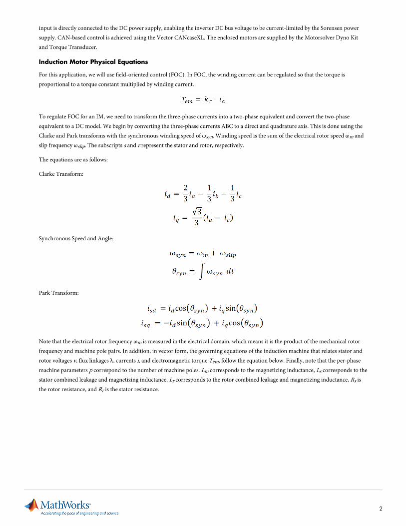
From the IM equations, we know that if we independently control the flux-producing current isd and torque-producing current isq, wewill generate the electromagnetic torque (Figure 2). We can make tradeoffs when selecting the ideal flux- and torque-producing currentcomponents. For example, at light loads it may be desirable to reduce the flux-producing current to reduce system losses, or to controlthe two currents to obtain the peak torque-per-machine ampere.
Figure 2. High-level diagram of the IM torque and flux control.
We will run the machine at its rated flux until field weakening occurs. After entering the rated speed for field weakening, we will reducethe current isd inversely as a function of rotor speed.
To control the machine we need to transform the stator feedback currents to their synchronous DC equivalents using mechanical speedand Clarke and Park transforms. Regulation of the stator currents requires the use of an induction machine motor model to estimate the
3
machine flux. Using proportional-integral (PI) control, we transform the two currents into the stator DQ voltages vsd and vsq. We thenuse vsd and vsq to calculate the duty cycle commands that feed the three-phase inverter using a space vector modulation technique.
Building and Implementing the Closed-Loop IM and DC Dynamometer System
To implement the dynamometer system, we do the following:
1. Extract IM parameters using finite element analysis (FEA)
2. Simulate a closed-loop system model consisting of the IM controller and the plant
3. Generate code to deploy the IM and DC motor controllers to the TI F28335
4. Control, calibrate, and monitor the system with a Vector CANalyzer
Determining Motor Parameters
Often, the first step in creating the dynamometer setup is the most difficult. This step entails calculating or measuring the followinginternal motor parameters: magnetizing inductance Lm, stator combined leakage and magnetizing inductance Ls, rotor combined leakageand magnetizing inductance Lr, rotor resistance Rs, stator resistance Rr, rated mechanical speed, rated voltage, and rated slip speed.
There are two common approaches to the determination of motor parameters: calculating from a finite element analysis model, andtaking a physical measurement with load and no-load tests. We will use the FEA approach, which enables us to obtain the rotor- andstator- rated voltages, currents, and flux, decomposed to the direct and quadrature axis. Once we know the relationship between flux andcurrent, we can calculate the rated stator d-axis current from the equations.
When the motor parameters are established, we convert them into Simulink data objects. We can then specify numerical value, validranges, data types, and other important attributes, and tune model gains without manipulating the model files.
Creating the System Model
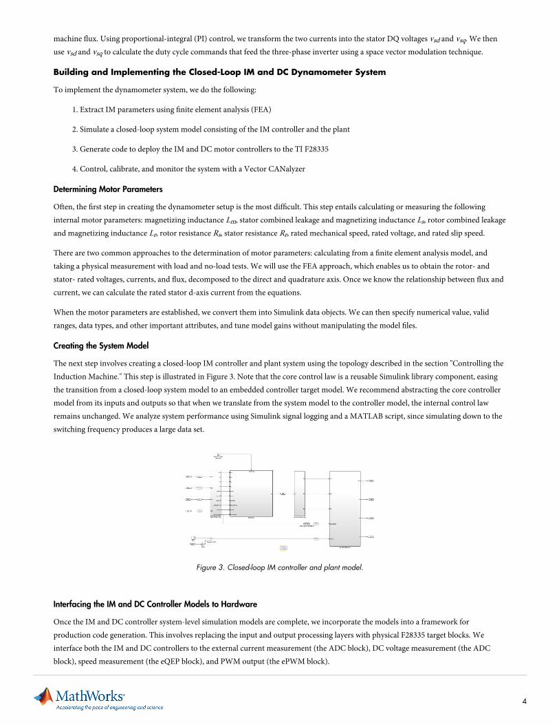
The next step involves creating a closed-loop IM controller and plant system using the topology described in the section "Controlling theInduction Machine." This step is illustrated in Figure 3. Note that the core control law is a reusable Simulink library component, easingthe transition from a closed-loop system model to an embedded controller target model. We recommend abstracting the core controllermodel from its inputs and outputs so that when we translate from the system model to the controller model, the internal control lawremains unchanged. We analyze system performance using Simulink signal logging and a MATLAB script, since simulating down to theswitching frequency produces a large data set.
Figure 3. Closed-loop IM controller and plant model.
Interfacing the IM and DC Controller Models to Hardware
Once the IM and DC controller system-level simulation models are complete, we incorporate the models into a framework forproduction code generation. This involves replacing the input and output processing layers with physical F28335 target blocks. Weinterface both the IM and DC controllers to the external current measurement (the ADC block), DC voltage measurement (the ADCblock), speed measurement (the eQEP block), and PWM output (the ePWM block).
4
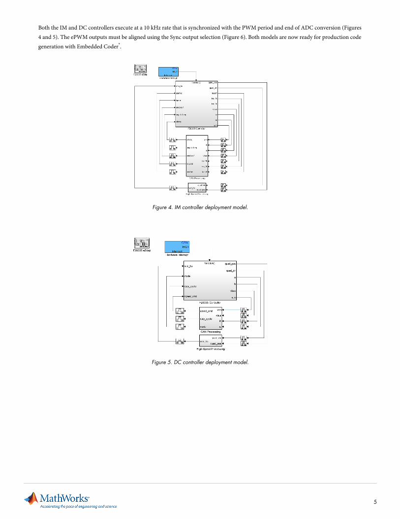
Both the IM and DC controllers execute at a 10 kHz rate that is synchronized with the PWM period and end of ADC conversion (Figures4 and 5). The ePWM outputs must be aligned using the Sync output selection (Figure 6). Both models are now ready for production codegeneration with Embedded Coder®.
Figure 4. IM controller deployment model.
Figure 5. DC controller deployment model.
5
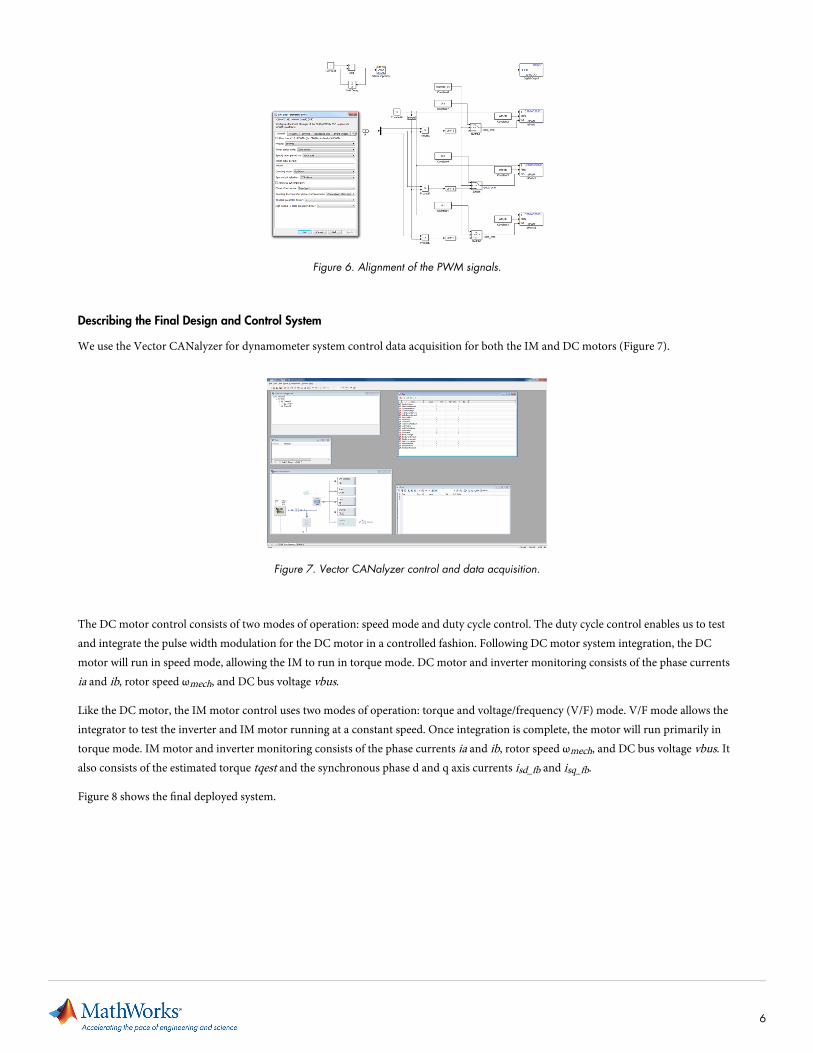
Figure 6. Alignment of the PWM signals.
Describing the Final Design and Control System
We use the Vector CANalyzer for dynamometer system control data acquisition for both the IM and DC motors (Figure 7).
Figure 7. Vector CANalyzer control and data acquisition.
The DC motor control consists of two modes of operation: speed mode and duty cycle control. The duty cycle control enables us to testand integrate the pulse width modulation for the DC motor in a controlled fashion. Following DC motor system integration, the DCmotor will run in speed mode, allowing the IM to run in torque mode. DC motor and inverter monitoring consists of the phase currentsia and ib, rotor speed ωmech, and DC bus voltage vbus.
Like the DC motor, the IM motor control uses two modes of operation: torque and voltage/frequency (V/F) mode. V/F mode allows theintegrator to test the inverter and IM motor running at a constant speed. Once integration is complete, the motor will run primarily intorque mode. IM motor and inverter monitoring consists of the phase currents ia and ib, rotor speed ωmech, and DC bus voltage vbus. Italso consists of the estimated torque tqest and the synchronous phase d and q axis currents isd_fb and isq_fb.
Figure 8 shows the final deployed system.
6
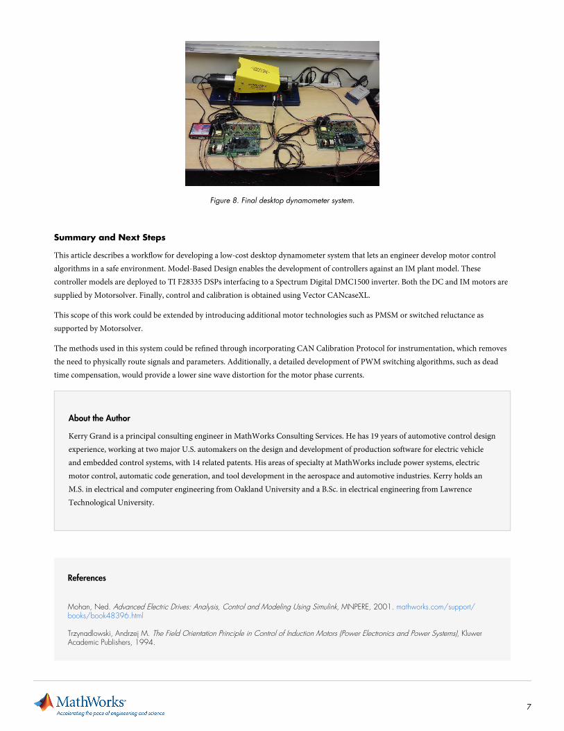
Figure 8. Final desktop dynamometer system.
Summary and Next Steps
This article describes a workflow for developing a low-cost desktop dynamometer system that lets an engineer develop motor controlalgorithms in a safe environment. Model-Based Design enables the development of controllers against an IM plant model. Thesecontroller models are deployed to TI F28335 DSPs interfacing to a Spectrum Digital DMC1500 inverter. Both the DC and IM motors aresupplied by Motorsolver. Finally, control and calibration is obtained using Vector CANcaseXL.
This scope of this work could be extended by introducing additional motor technologies such as PMSM or switched reluctance assupported by Motorsolver.
The methods used in this system could be refined through incorporating CAN Calibration Protocol for instrumentation, which removesthe need to physically route signals and parameters. Additionally, a detailed development of PWM switching algorithms, such as deadtime compensation, would provide a lower sine wave distortion for the motor phase currents.
About the Author
Kerry Grand is a principal consulting engineer in MathWorks Consulting Services. He has 19 years of automotive control designexperience, working at two major U.S. automakers on the design and development of production software for electric vehicleand embedded control systems, with 14 related patents. His areas of specialty at MathWorks include power systems, electricmotor control, automatic code generation, and tool development in the aerospace and automotive industries. Kerry holds anM.S. in electrical and computer engineering from Oakland University and a B.Sc. in electrical engineering from LawrenceTechnological University.
References
Mohan, Ned. Advanced Electric Drives: Analysis, Control and Modeling Using Simulink, MNPERE, 2001. mathworks.com/support/books/book48396.html
Trzynadlowski, Andrzej M. The Field Orientation Principle in Control of Induction Motors (Power Electronics and Power Systems), KluwerAcademic Publishers, 1994.
7

Products Used
▪ MATLAB
▪ Simulink
▪ Embedded Coder
Learn More
▪ Advanced Electric Drives: Analysis, Control and Modeling
Using Simulink
▪ The Field Orientation Principle in Control of Induction Motors
▪ Embedded Code Generation for AC Motor Controllers
See more articles and subscribe at mathworks.com/newsletters.
Published 201392129v00
mathworks.com© 2013 The MathWorks, Inc. MATLAB and Simulink are registered trademarks of The MathWorks, Inc. See www.mathworks.com/trademarksfor a list of additional trademarks. Other product or brand names may be trademarks or registered trademarks of their respective holders.
8