Embed Size (px)
Citation preview

1530
E031019 000823
CPUs to the process modulesCPUs to the process modules
systron® S 200 - S 250 - S 250csystron® S 200 - S 250 - S 250c
With these CPUs, the system works as a small modular PLC.With its programming interface RS 232 the PLC is programmable with allPCs without need of a special interface.Programming is done according to IEC 1131-3 with instruction list, functiondiagram or ladder diagram.Program modules including counters, timers, PID loop controllers and manymore are integrated in the operating system.
Stand-alone PLC
With S 200, the system works as a small, modular PLC.Expandable with I/O modules, systron® PM is the solution for PLCapplications where small mechanical size is critical.
CP
U s
ystr
on
® S
200
- S
250
- S
250c
Decentral intelligence at the fieldbus
Combining a bus module with a CPU S 250 or S 250c results in a fieldbusstation with its own intelligence.
It is a slave at the bus, but able to process a separate program.It is possible to preprocess data, to execute function parts, or to enableprocesses in case of bus failures.
Both CPUs can be used as stand-alone PLCs - for processes that requiremore complex performance.
S 250 and S 250c offer memory of 2 k instructions. S 250c additionally hasindirect, retentive memory of over 6100 flag words - ideal in cases where alarge data memory is needed.S 250c additionally contains a real-time clock as a program module in itsoperating system.
Easy to use software according to IEC 1131-3
45 mm width Flexible and expandable Easy to use software for bus connection (S 250/ S 250c)

1531
Technical data
Accessories P/N:
Micro PLCs P/N:
systron® S 200 2 423 410 00
E031020 000823
Supply power Vv = 24 V DCReference potential, Ground of Vv
GND
Operating mode LED
ERROR LED
LED indicates high-speed counter active
LED indicates dataexchange at E- Bus
Programmable logiccontroller systron® S 200
Operation
The S 200 is the CPU for process modules.Per application requirements, connect I/Omodules and intelligent modules by a flat ribboncable.S 200 contains an operating memory (EEPROM)for 2k instructions and a full range of programmingcommands. The programming system iscompatible with the WINDOWS operating systemand complies with IEC 1131-3.
Design
Approvals:
Supply voltage 20...30 V DCPower consumption 60...320 mA at 24 V, depending on configurationResidual ripple < 10%Reverse polarity protection diodeSupply for expansion modules 500 mA up to 45 °C
400 mA up to 55 °CBuilt-in memory 4 KByte EEPROM/2048 InstructionsMaximum configurationInputs digital 48Inputs analog 24Outputs digital Transistor 48
Relay 24Outputs analog 24Timers 32Counters 32High-speed counter 1, 10 kHzInstructions 2 KFlags bit 512Flags word 256Retentive flag words 16Cycle time Bit/ 2.4 ms/ K
Word 4 ms/ KProgramming interface RS 232, electrically isolated
Socket, 8-pin, Mini-DINDisplay of operating statusPOWER green LEDERROR red LEDExpansion bus (E-Bus) green LEDHigh-speed counter (Counter) green LEDRUN green LEDDielectric withstandExternal connections against internal connections acc. to VDE 0160, 500 V ACVibration and shock acc. to IEC 68-2-6 10...57 Hz constant amplitude 0.15 mm
57...150 Hz constant acceleration 2 GNoise immunity acc. to IEC 801-2
acc. to IEC 801-4Operating temperature 0 ... +55 °CStorage temperature - 25 ... +75 °CTerminals, screw max. 2 x 14 AWG (2 x 2.5 mm2)Weight 0.44 lb (200 g)Dimensions (W x H x D) 45 x 82.5 x 100 mm
Integrated EEPROM memory for 2048 instructionsExpandable with up to 12 expansion modulessystron® PMProgramming interface RS 232High-speed counter input (max. 10 kHz)Electrical isolation between external supply, processor,programming interface and high-speed counter
POWERLED
Programminginterface
Marker
High-speedcounter(up to 10 kHz)
Maximum configuration
12 Expansion modules total max. 6 of each type internal supply for expansion modules
400 mA max.
Max. no. of expansion modules per S 200
48 digital inputs with 6 PMI modules48 digital outputs with 6 PMO transistor
modulesormixed configuration with PMO Relay,but 6 PMO modules maximum
24 digital outputs with 6 PMO Relay modules24 analog inputs with 6 PMAI24 analog outputs with 6 PMAO4 high-speed counters PMC8 BALLUFF linear displacement transducers
with 2 PMT24 potentiometers with 6 potentiometer
modules PMP24 values with 6 measuring and monitoring
relays PMM
Integrated functions
max. 48 inputs / 48 outputs digitalmax. 24 inputs/ 24 outputs analog512 bit- and 256 word flags32 timers, 32 counterscycle time 2.4 ms for 1024 binary instructionsarithmetics and PID controller integrated inthe operating system
Connection cable S 200 - PC 2 423 419 00Programming software prosys200acc. to IEC 1131-3 German 2 423 405 50
English 2 423 405 51French 2 423 405 52
System Manual systron® S 200/ S 250German 2 423 402 50English 2 423 402 51French 2 423 402 52

1532
RS 232
RS 485
MODBUS
E031021 000802
systron® S 250 and S 250c - Intelligence at the bussystron® S 250 and S 250c - Intelligence at the bus
S 250:
4 k instructions up to 12 expansion modules to be connected for use with or without fieldbus module
Data pre-processing for bus communication Continues processing if bus fails
Powerful PLC single station
S 250c:
Also includes real-time clock integrated as program module high-capacitive retentive data storage 10 years buffer time without external supply voltage

1533
Technical data
Accessories P/N:
Micro PLCs P/N:systron® S 250 2 423 411 00systron® S 250c 2 423 411 10
E031022 000823
PLCs for bus connectionsystron® S 250 and S 250c
Operation
The CPUs S 250 and S 250c offer the samefunctions as the S 200 - and more: the ability toconnect them to a bus system.Further, both PLCs have a 4 k memory whichmakes them suitable also as a stand-alone PLCfor more complex applications.
S 250 - decentral intelligence at the bus
S 250 can preprocess data which makes buscommunication much faster.S 250 can also be used where processes mustcontinue in case of bus failures.Data exchange between bus module and PLC isdone by a defined flag word range.
S 250c - with clock and high capacity datamemory
S 250c additionally offers an integrated real-timeclock and a retentive memory range of 5887 flagwords - ideal for receipt management and similarapplications.
Design
Integrated functions
max. 48 inputs/48 outputs digital max. 24 inputs/24 outputs analog 512 bit- and 256 word flags 32 timers, 32 counters cycle time 2.4 ms for 1024 binary instructions arithmetics and PID controller integrated inthe operating system, S 250c has anadditional clock module
Approvals:
Integrated EEPROM memory for 4096 instructionsCan be connected to bus modules and interface modulessystron® PMAt S 250c:real-time clock integratedhigh-capacity retentive memoryExpandable with up to 12 expansion modulessystron® PMProgramming interface RS 232High-speed counter input (max. 10 kHz)Electrical isolation between external supply, processor,programming interface, and high-speed counter
Max. no. of expansion modulesper S 250/ S 250c12 Expansion modules maximum;max. 6 expansion modules per type
PMI 6PMO 6PMAI 6PMAO 6PMC 4PMT 2PMM 6PMP 6PMSC 4 (only with S250c)PMBM 1PMCI 2No. of modules also depend on powerconsumption.
Bus systems and S 250/ S 250c
The combining of bus system <-> S 250/ S 250cis done by a bus module systron® PM.Data to be exchanged are offered in a defined flagword range of the S 250.It is therefore not possible to access directly toI/O modules. If this is neccessary, I/O modulescan be placed between a bus module and a PLC.Following combinations are possible:INTERBUS S 250(c)PROFIBUS-DPMODBUSCANopenDeviceNet
Interface modulesRS 232 andRS 485
Supply power Vv = 24 V DCReference potential, Ground of Vv
GNDBus connectioncable
POWERLED
Programminginterface
Marker
high-speedcounter(up to 10 kHz)
Operating mode LED
ERROR LED
BUSY LED
LED indicates high-speed counter active
LED indicates dataexchange at E- Bus
Connection cable S 200 - PC 2 423 419 00Programming software prosys200acc. to IEC 1131-3 German 2 423 405 50
English 2 423 405 51French 2 423 405 52
System Manual systron® S 200/ S 250German 2 423 402 50English 2 423 402 51French 2 423 402 52
Supply voltage 20...30 V DCPower consumption 60...320 mA at 24 V, depending on configurationResidual ripple < 10%Reverse polarity protection diodeSupply for expansion modules 500 mA up to 45 °C
400 mA up to 55 °CBuilt-in memory 8 KByte/4096 InstructionsType of memory S 250: EEPROM
S 250c: NVSRAM (int. battery,life > 10 years)Maximum configurationInputs digital 48Inputs analog 24Outputs digital Transistor 48
Relay 24Outputs analog 24Timers 32Counters 32High-speed counter 1, 10 kHzInstructions 4 KFlags Bit / word 512 / 256Retentive flag words S 250: 48 S 250c: 6143 (5887 rem.)Retentivity buffer 10 years without external supply powerCycle time Bit/ 2.4 ms/ K
Word 4 ms/ KProgramming interface RS 232, electrically isolated
Socket, 8-pin, Mini-DINDielectric withstandExternal connections <-> internal connections acc. to VDE 0160, 500 V ACVibration and shock acc. to IEC 68-2-6 10...57 Hz constant amplitude 0,15 mm
57...150 Hz constant acceleration 2 GNoise immunity acc. to IEC 801-2
acc. to IEC 801-4Degree of protection Terminals IP 20
Housing IP 50Ambient temperatureOperating temperature 0 ... +55 °CStorage temperature - 25 ... +75 °CTerminals, screw max. 2 x 14 AWG (2 x 2.5 mm2)Weight 0.44 lb (200 g)Dimensions (W x H x D) 45 x 82.5 x 100 mm

1534
000823FL_00008
CAN-MasterCAN-MasterCAN-MasterCAN-MasterCAN-Master
Maximum configuration
Per PM CAN module
48 digital inputs with 6 PMI modules48 digital outputs 6 PMO transistor modules
ora mixed configuration with PMO relay,but 6 PMO modules maximum
24 digital outputs with 6 PMO relay modules16 analog inputs with 4 PMAI16 analog outputs with 4 PMAO2 counter modules PMC8 BALLUFF linear displacement transducers
with 2 positioning modules PMT-> max. 2 PMT or 4 PMAI/ PMAO modules
total6 potentiometer modules PMP1 PLC S 250 or S 250c
Supply voltage Vv = 24 V DCCommon
GND
POWER ONLED
LED indicatesdata exchangeon bus
Marker
Cable shield,connected capacitivelywith protectiveconductor
CAN busconnection
Equipotentialbonding
Station- ID
LED indicatesdata exchangeon E-Bus
systron® PM Bus moduleCAN-Master
Operation
The bus module CAN-Master, combined with I/Omodules systron® PM, processes data of sensorsand actuators from various manufacturers, thusenabling communication by a simple protocol.
PM CAN-Master works together with an S 250 orS 250c.CAN-Master is able to start a CAN bus system.Data can be exchanged by Process Data Objects.
Design
Can start-up a CAN bus systemWorks together with a S 250 or S 250cAutomatic baud rate detectionHigh transmission reliabilityExtremely short reaction times
System ManualGerman 2 423 403 50English 2 423 403 51French 2 423 403 52
Bus module CAN-Master 2 423 427 10
Complying with DS301/ DS-401Supply voltage 24 V DCVoltage range including ripple 20...30 V DCPower consumption 60...320 mAReverse polarity protection DiodeElectrical isolation L+/ L- <-> internal supply DC/ DC convertersCAN <-> internal bus OptocouplerReaction to supply interrruption 10 ms bypass time at 24 V rated voltageInterface ISO/ DIS 11898Protocol CANopen Min-Boot-upDevice profile -Recommended cable CANTransmission rate 20 kbps / 125 kbps / 250 kbps / 500 kbpsExpansion max. 1000 m at 20 kbps
max. 100 m at 500 kbpsSystem configurationNumber of stations max. 127Address setting DIP switchesInternal supply for expansion modules0° ... +55° C 400 mAPLC Interface S 250 (c)Noise immunity acc. IEC 1000-4-4, class 3, 2 kVElectrical isolationSupply/ CPU yesCAN bus/ CPU yesDielectric withstanding voltage acc. to VDE 0160External <-> internal connections 500 V ACExternal <-> CAN connections 500 V ACAmbient temperatureOperating temperature 0 ... +55°CStorage temperature -25 ... +75°CDegree of protectionTerminals IP 20Housing IP 50Terminals, screw max. 2 x 14 AWG (2 x 2.5 mm2)Weight approx. 0.44 lb (200 g)Dimensions (W x H x D) 45 x 82.5 x 100 mm
Technical data
Accessories P/N:
Bus modules systron® PM P/N:
Approvals:

1535
000823FL_00006
Supply voltage Vv = 24 V DCReference potential
GND
Shield connectionwith capacitanceground
Terminals for E/A-Bus (RS 485)DGND:Data reference potentialRS 485
Expansionaddress LEDs
Expansionactive LED
Expansionfault LED
systron® PMBM ExpansionSchiele E/A-Bus master
Operation
The systron® PMBM Schiele I/O bus mastermodule provides a link on a two-wire cablebetween the S 250c CPU and a remote stationsuch as the S 400, Man Machine InterfaceIMM 40-70 (except IMM 20) and processmodule PM E/A.A maximum of 7 remote expansions with a totalof 112 logical Inputs, 112 logical Outputs and56 Analog Inputs and Outputs and 7 high speedcounters are allowed.These remote I/Os are automatically seen bythe S 250c as their own I/Os. The network isprogrammed with the usual programmingsoftware of the S 250c.
Design
Simple protocol E/A bus MasterUp to 7 expansion units connectable to systron®
S 250 and S250c
Supply voltage 24 V DCVoltage range including ripple 20...30 V DCPower consumptionexternal (onto 24 V DC) ≤ 30...50 mAinternal (from PM) ≤ 80 mAInterface RS 485Transmission rate 187.5 kBaudDistance to- next station max. 600 m- total max. 600 mSystem configurationNumber of slave stations 7 expansions like S 400, PM E/A or IMMAmount of remote I/O operands 7 Digital Input and Output words
56 Analog Input and Output words7 Input words for high speed counters
Display of operational statusPOWER (Power) green LEDERROR (Error) red LEDSystem OK (Busy) green LEDExpansion address (Address) 3 x green LEDExpansion active (Active) green LEDExpansion fault (Fault) red LEDNoise immunity acc. to IEC 1000-4-4, class 3, 2 kVElectrical isolationSupply/ CPU yesE/A bus/ CPU yesDielectric withstanding according to VDE 0160External <-> internal connections 500 V AC, 1 minuteExternal <-> bus connections 500 V AC, 1 minuteAmbient temperatureOperating temperature 0 ... +55°CStorage temperature -25 ... +75°CDegree of protectionTerminals IP 20Housing IP 50Terminals, screw max. 2 x 14 AWG (2 x 2.5 mm2)Weight approx. 0.55 lb (250 g)Dimensions (W x H x D) 45 x 82.5 x 100 mm
POWERLED
ERRORLED
System ok.LED
Bus termination
Marker
Maximum configuration
Up to 7 remote expansions with a total I/O amountof (remote I/O operands):
112 digital Inputs (7 Input words) 112 digital Outputs (7 Output words) 56 analog Inputs and Outputs (112 I/O words) 7 high speed counters (7 Input words)
depending on the number of locallyconnected I/Os onto the S 250 CPU
Approvals: in process
Bus module Schiele E/A-Bus master 2 423 476 00
Accessories P/N:
Modules systron® PMBM P/N:
Technical data
System Manual systron® S 200 / S 250German 2 423 402 50English 2 423 402 51French 2 423 402 52

1536
E033004 000623
All terminals are plug-in type.
Automation system systron® S 400
Outputs
Fuse for transistor outputs(internal)
Battery and address switches
Analog I/O interface
Plug for EEPROM
Programming interfaceRS 232 at the basic unitorFieldbusor interfacecommunication
Input LEDs
Inputs
Input supplyDC versions: external input 24 VDCneeded
AC versions:+24 VDC power supply (short-circuitproof), for input section electronics, isbuilt-into the product.
Marker field foroutputs
Output LEDs
PLC Status
PLC reference number
Marker field forinputs
Fuse
Power supply terminals
I/O bus terminals
Automation system systron® S 400
+24 V for transistoroutputs wiredinternally from LEDsupply

1537
Technical data
systron® S 400
E033005 000823
Approval: Nr. 91294 HH
Supply voltage 24 V DC or 230 V ACUp to 7 units on Schiele E/A-Bus.Process modules and IMM also connectable to E/A-BusUp to 28 PLC systems with optional INTEL BitbusComplete flexibility with plug-in terminals and plug-inEEPROMReal-time clock integrated in operating systemOptional:4 analog inputs and 1 analog outputPID controller integrated in the operating systemBitbus interfaceRS 232 interfaceRS 485-MODBUS interfaceProgramming interface RS 232
Operation
S 400 is a powerful, compact PLC which isavailable with several expansion ranges:
- 1 k or 4 k instructions- 8 inputs / 8 outputs: relay
8 inputs/ 8 outputs: transistor16 inputs/ 16 outputs: transistor16 inputs/ 12 outputs: relay
S 400 offers a user friendly range of commandsintegrated into the operating system.
S 400 is programmed directly with a standard PC;a plug-in card is not necessary.Two programming software types are available: software running with DOS instruction list and
ladder diagram IEC 1131-3 running with MS-WINDOWS for
instruction list, ladder diagram and functionlist.
Expandability
Schiele E/A-Bus
With the Schiele E/A-Bus, up to 7 stations can beconnected within a distance of up to 600 meters.
Connectable devices
The following devices can be connected to theE/A-Bus:- systron® S 400 as an expansion device- Process modules systron® PM- Interfaces Man-Machine IMM 40,
IMM 50 and IMM 70
Networking with Bitbus
With Bitbus, it is possible to connect S 400 to- advanced systems- systems from other manufacturers- larger systems- intelligent bus-connectable sensors and
actuators
-> 28 PLC systems in Multimaster mode-> up to 63 in Standard mode.
Supply voltage 24 V DC 230 V ACVoltage ranges 19.5...29 V DC 187...252 V ACFuse 1.6 A slow 160 mA slowPower consumption 20 VAInputs 8 or 16 x 24 V DCInput current 8 mA typ.Input delay 3 ms typ.Relay outputs 8 or 12 x 250 V AC/ 2 A with RC circuitResidual current < 5 mAElectric circuit 2 outputs with common connectionOhmic load 24 V DC/ 2 A 230 V AC/ 2 AInductive load 24 V DC/ 1.5 A 230 V AC/ 0.2 AElectrical life, max. 3 x 10⁵ operationsMechanical life, max. 30 x 106 operationsTransistor outputs 8 or 16 x 24 V DC ± 20 %, 0.5 A PNP
Parallel connection up to 4 outputs permissibleResidual ripple < 10 %Power consumption 90 mA typ.Residual current < 0.2 mAPermissible total current, max. 4 A
short-circuit proof, overload messageAnalog inputs 4 x 0...10 VResolution 8 BitInput resistance > 100 KΩConstant voltage for analog inputs +10 V DC/ 20 mA, short-circuit proofAnalog outputs 1 x 0...10 VResolution 8 BitInternal resistance 270 ΩTimers 32 internal timers, 10 ms ... 18.2 h,
16 timers with retentive memoryCounters 32 internal counters, 0... 65535
16 counters with retentive memory1 high-speed counter 10 kHz
Cycle time Bit typ. 3 ms/ k instructions,Bit and word typ. 5 ms
additional 3ms per expansion unitInterfaces RS 232 as programming interface
optional 2nd RS 232 as communication interfaceE/A-Bus RS 485 , 2-wire data cable, up to 600 mFieldbus RS 485, 9pin Min-D plugBuffer battery Lithium battery, approx. 5 years lifeMemory 1 k or 4 k instructions/ RAM,
plug-in EEPROM optionalVibration test 2 G, 10...100 HzShock test 15 G, 20 msTerminals plug-in, for 16 AWG (1.5 mm2)Operating temperature 0...+55 °C, at more than +40 °C ventilation requiredStorage temperature -40°C ... +75 °CWeight approx. 3.3 lb (1.5 kg) (230 V vers.) approx. 2.2 lb (1 kg ) (24 V vers.)Dimensions (W x H x D) 167 mm x 258 mm x 64 mm

1538
E033006 000823
221.
2
225.
7
150
154.5
167
M425
856
64
systron® S 400
Versions: Basic unit or Expansion unit
Inputs/ outputs Memory Supply voltage Ref. no.
16 E/ 12 A (Relay) 4 K instructions 230 V AC 2 407 400 2124 V DC 2 407 400 01
16 E/ 16 A (0.5 A, 24 V DC) 4 K instructions 230 V AC 2 407 401 2124 V DC 2 407 401 01
8 E / 8 A (Relay) 1 K instructions 230 V AC 2 407 405 2024 V DC 2 407 405 00
8 E/ 8 A (0.5 A, 24 V DC) 1 K instructions 230 V AC 2 407 406 2024 V DC 2 407 406 00
16 E/ 12 A (Relay) + PID + Field bus interface 4 K instructions 230 V AC 2 407 440 2624 V DC 2 407 440 06
With option: 4 Analog inputs/ 1 Analog output
Inputs/ outputs Memory Supply voltage Ref. no.
16 E/ 12 A (Relay) 4 K instructions 230 V AC 2 407 410 2124 V DC 2 407 410 01
16 E/ 16 A (0.5 A, 24 V DC) 4 K instructions 230 V AC 2 407 411 2124 V DC 2 407 411 01
8 E / 8 A (Relay) 1 K instructions 230 V AC 2 407 415 2024 V DC 2 407 415 00
8 E/ 8 A (0.5 A, 24 V DC) 1 K instructions 230 V AC 2 407 416 2024 V DC 2 407 416 00
16 E/ 12 A (Relay) + PID 4 K instructions 230 V AC 2 407 410 2624 V DC 2 407 410 06
16 E/ 16 A (0.5 A, 24 V DC) + PID 4 K instructions 230 V AC 2 407 411 2624 V DC 2 407 411 06
16 E/ 16 A (Transistor) + PID + RS 232 4 K instructions 230 V AC 2 407 431 2624 V DC 2 407 431 06
16 E/ 16 A (0.5 A, 24 V DC) + PID + Bitbus interface 4 K instructions 230 V AC 2 407 421 2624 V DC 2 407 421 06
16 E/ 16 A (0.5 A, 24 V DC) + PID+ RS 232 MODBUS/ RTU Slave 4 K instructions 24 V DC 2 407 451 06
16 E/ 16 A (0.5 A, 24 V DC) + PID+ RS 485 MODBUS/ RTU Slave 4 K instructions 24 V DC 2 407 461 06
Order references
Accessories
Ref. no.
Programming cable PC <-> S 400 2 407 521 00
Poti module (analog) 2 407 516 00
Remote potentiometer10 kΩ 22.5 mm 3 701 805 00
EEPROM 4 K,write protection switchable 2 407 482 35
Data lineAnalog interfacelength 1 m) 2 407 524 00
Battery 4 412 821 00
Level converter 20 mA/ 10 V 2 407 517 00
User Manual S 400English 2 408 803 10German 2 408 803 00
Dimensions in mm
1539
E033007 000823
Programming
prosys 200 acc. to IEC 1131-3 English 2 423 405 51German 2 423 405 50French 2 423 405 52
prosys 200 demo version English 2 423 405 71also available on internet: German 2 423 405 70www. entrelec.com French 2 423 405 72
sh400 English 2 408 804 30German 2 408 804 10
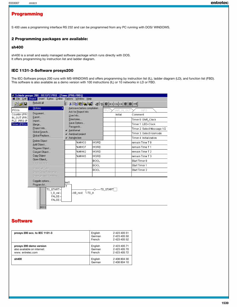
S 400 uses a programming interface RS 232 and can be programmed from any PC running with DOS/ WINDOWS.
2 Programming packages are available:
sh400
sh400 is a small and easily managed software package which runs directly with DOS.It offers programming by instruction list and ladder diagram.
IEC 1131-3-Software prosys200
The IEC-Software prosys 200 runs with MS-WINDOWS and offers programming by instruction list (IL), ladder diagram (LD), and function list (FBD).This software is also available as a demo version with 100 instructions (IL) or 10 networks in LD or FBD.
SoftwareSoftware
Programming

1540
0901T 010330
Integrated Workstations
PC based controland display
CoDeSys® software PC card to matchbus system
• Compact PC based control• Pentium PC processor• High brightness, anti-glare, flat panel touch screen display• External CD and 3.5" floppy drive• Ethernet card (selected models)• CoDeSys® PC control software• Selectable PC cards to match your bus system• High speed serial ports and bi-directional parallel port
Programming Screen Sample
Operation
Select our integrated workstations for a variety of PC basedgraphical operator interfaces. Systems are offered in bench andpanel mount configurations with full touch screen displays andfeature complete open access for expansion and service.
The PC features a compact 3 slot chassis, external CD andfloppy drives, and a shock mounted hard drive for reliableindustrial operation. The touch screen is rated IP 65,NEMA 4X, and NEMA 12X.
The software package, designated “CoDeSys®”, offers a fullimplementation of the IEC 1131-3 standard. CoDeSys programmethods include instruction list, ladder logic, structured text,functional block diagram, and sequential flow chart. The run-timesoftware, the develop package, and the man machine graphicsoftware are included. In addition, CoDeSys offers a built-ingraphic package, animated graphics, and a built-in DDE serverand OPC for interface with other software.
To avoid limiting system I/O, the CoDeSys software does nothave “tag limits.” CoDeSys features extensive libraries thatinclude many standard and special purpose modules.Contact Entrelec for further details.
Integrated Workstation P/N(standard model)Pentium PC with 0360 004 45 12" color touch screenExternal CD drive 0360 004 47External 3.5" floppy drive 0360 004 46Ethernet card 0360 004 48CoDeSys® PC control software 2 423 407 01PC card (bus system compatible) Contact EntrelecConfiguration software 2 423 408 50
Contact Entrelec for part numbers of other models.See data sheet on next page.
1541
0902T 010330
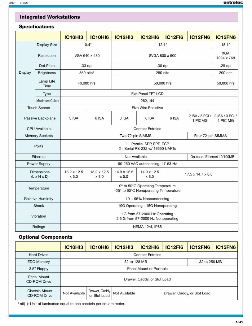
Integrated Workstations
Specifications
Optional Components
IC10HI3 IC10HI6 IC12HI3 IC12HI6 IC12FI6 IC12FN6 IC15FN6Display Size 10.4" 12.1" 15.1"
Resolution VGA 640 x 480 SVGA 800 x 600XGA
1024 x 768
Dot Pitch .33 dpi .30 dpi .29 dpi
Brightness 350 nits1 250 nits 200 nits
Lamp Life 40,000 hrs 50,000 hrs 50,000 hrsTime
Type Flat Panel TFT LCD
Maximum Colors 262,144
Touch Screen Five Wire Resistive
Passive Backplane 3 ISA 6 ISA 3 ISA 6 ISA 6 ISA2 ISA / 3 PCI / 2 ISA / 3 PCI /
1 PICMG 1 PIC MG
CPU Available Contact Entrelec
Memory Sockets Two 72-pin SIMMS Four 72-pin SIMMS
Ports1 - Parallel SPP, EPP, ECP
2 - Serial RS-232 w/ 16550 UARTs
Ethernet Not Available On board Ethernet 10/100MB
Power Supply 90-260 VAC autosensing, 47-63 Hz
Dimensions 13.2 x 12.5 13.2 x 12.5 14.9 x 12.5 14.9 x 12.5(L x H x D) x 5.0 x 8.0 x 5.0 x 8.0
17.5 x 14.7 x 8.0
Temperature0º to 50°C Operating Temperature
-25º to 60ºC Nonoperating Temperature
Relative Humidity 10 ~ 95% Noncondensing
Shock 10G Operating - 15G Nonoperating
Vibration1G from 57-2000 Hz Operating
2.5 G from 57-2000 Hz Nonoperating
Ratings NEMA 12/4, IP65
IC10HI3 IC10HI6 IC12HI3 IC12HI6 IC12FI6 IC12FN6 IC15FN6Hard Drives Contact Entrelec
EDO Memory 32 to 128 MB 32 to 256 MB
3.5” Floppy Panel Mount or Portable
Panel MountDrawer, Caddy, or Slot Load
CD-ROM Drive
Chassis MountNot Available
Drawer, CaddyNot Available Drawer, Caddy, or Slot Load
CD-ROM Drive or Slot Load
1 nit(1): Unit of luminance equal to one candela per square meter.
Display
1542
E031023 000823
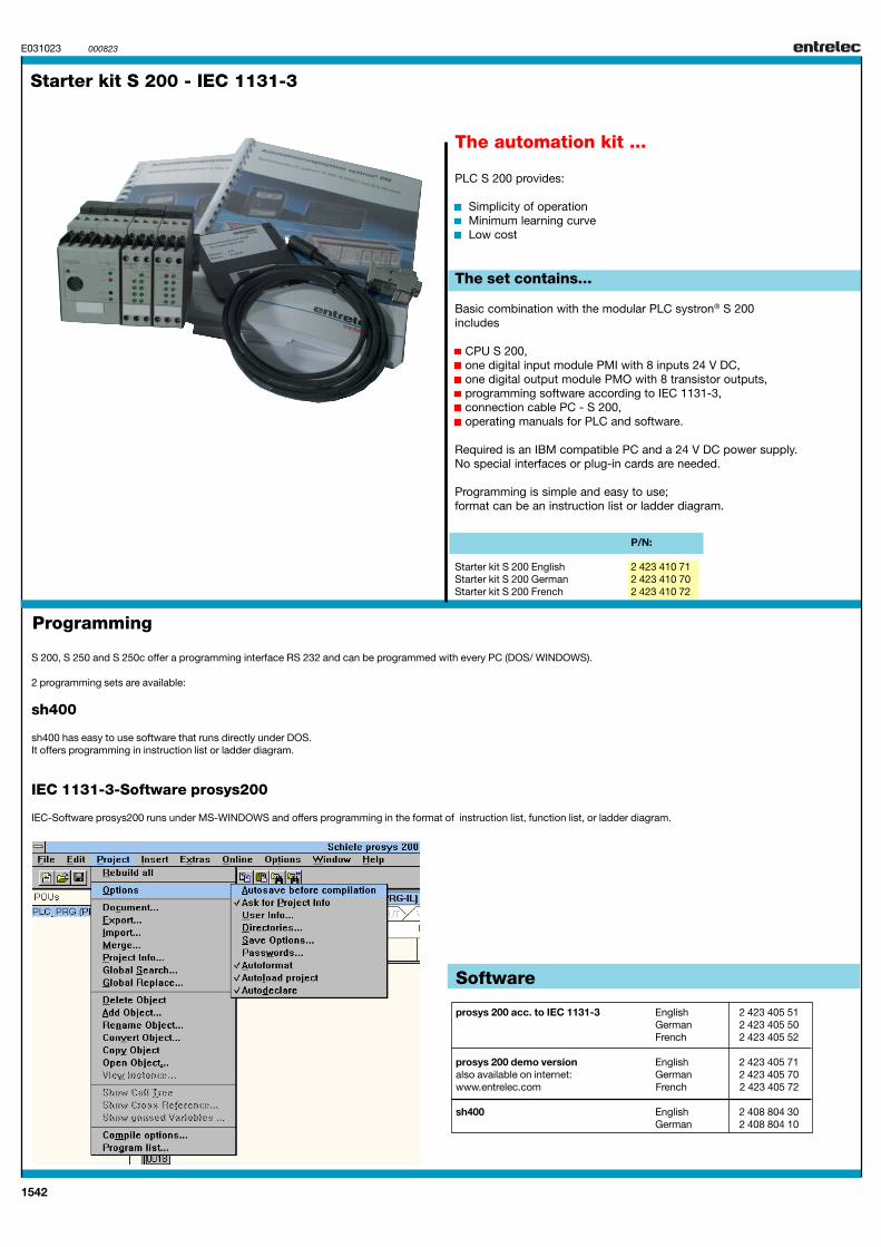
Starter kit S 200 - IEC 1131-3
The automation kit ...
PLC S 200 provides:
Simplicity of operation Minimum learning curve Low cost
The set contains...
Basic combination with the modular PLC systron® S 200includes
CPU S 200,one digital input module PMI with 8 inputs 24 V DC,one digital output module PMO with 8 transistor outputs,programming software according to IEC 1131-3,connection cable PC - S 200,operating manuals for PLC and software.
Required is an IBM compatible PC and a 24 V DC power supply.No special interfaces or plug-in cards are needed.
Programming is simple and easy to use;format can be an instruction list or ladder diagram.
P/N:
Starter kit S 200 English 2 423 410 71Starter kit S 200 German 2 423 410 70Starter kit S 200 French 2 423 410 72
Programming
S 200, S 250 and S 250c offer a programming interface RS 232 and can be programmed with every PC (DOS/ WINDOWS).
2 programming sets are available:
sh400
sh400 has easy to use software that runs directly under DOS.It offers programming in instruction list or ladder diagram.
IEC 1131-3-Software prosys200
IEC-Software prosys200 runs under MS-WINDOWS and offers programming in the format of instruction list, function list, or ladder diagram.
Software
prosys 200 acc. to IEC 1131-3 English 2 423 405 51German 2 423 405 50French 2 423 405 52
prosys 200 demo version English 2 423 405 71also available on internet: German 2 423 405 70www.entrelec.com French 2 423 405 72
sh400 English 2 408 804 30German 2 408 804 10
1543
E031024 000823
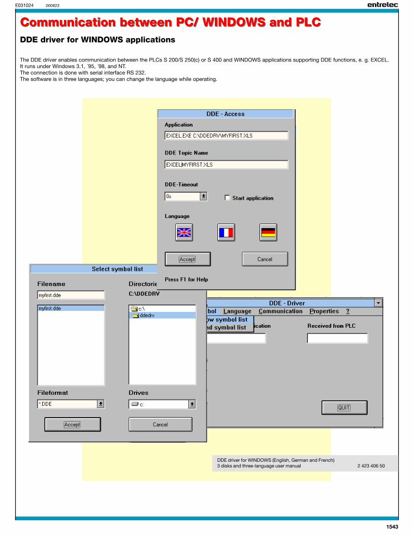
The DDE driver enables communication between the PLCs S 200/S 250(c) or S 400 and WINDOWS applications supporting DDE functions, e. g. EXCEL.It runs under Windows 3.1, ´95, ´98, and NT.The connection is done with serial interface RS 232.The software is in three languages; you can change the language while operating.
Communication between PC/ WINDOWS and PLCCommunication between PC/ WINDOWS and PLCDDE driver for WINDOWS applications
DDE driver for WINDOWS (English, German and French)3 disks and three-language user manual 2 423 406 50

1544
NOTES

1545
NOTES