Embed Size (px)
Citation preview

Course on Design of Steel Structures Prof. Damodar Maity
Department of Civil Engineering Indian Institute of Technology Kharagpur
Mod01 lecture 01Introduction to Limit State Design of Steel Structures
I welcome to the limit state design of steel structure class. The limit state design of steel
structure has been introduced in our Indian code in 2007. Before that, we used to design the
steel structure by the use of Working Stress Method and from 2007 onwards, the codel
provision has been changed and in 2007, the IS 800-2007 has been published where the entire
code has been discussed based on Limit State Design method.
Now coming to this course, today I will discuss about the probable content of the course,
which I am going to cover in next 60 lectures. I will inform what are the books you can
follow and what are the codes required for learning this course, and I will show you some
steel rolled section. What are their properties, how the parameters vary, how the parameters
are considered? Which parameters are considered? Which are given in the IS handbook SP-
6, I will just give you touch on that.
Now coming to the Limit State Design of steel structure, one thing we can say that now a
days, in every city or every country, wherever you see some skyscrapers, these are mostly
built with the steel. Steel has lot of advantages, which I will come later, and because of its
advantageous properties, we, the designer prefer for designing the structure with the steel.
Steel sections are massively used particularly in bridge structure and in transmission tower,
refinery well structure. Sometimes some water tanks, some high rise buildings, many
industrial buildings, sheds are made of steels. Steel is much stronger than the conventional
construction material like concrete, its strength to weight ratio is very high i.e. its weight is
very less and strength is very high. It is much ductile compared to concrete and, because of
its advantages designer prefers steel structure, though it is costly.
So if we design properly in a cost effective way, the cost can be minimized without
compromising the safety. Therefore, we need to know the design procedure properly and
may be in later, by knowing the design procedure we can make a computer code, we can
generate some computer algorithm, by the use of matlab or any other standard language like
C language, C++, java or we can use excel sheet also. In steel design, we need to iterate the
design process. We will assume certain member with certain dimensions and we will check

from limit state point of view, from ultimate strength point of view, from serviceability
criteria point of view. We will check certain steps and if we see these are not satisfied then we
have to increase the size and if we see it is satisfied then we can go for this particular section.
In case of limit state design, there are lot of procedures and calculations. Hence, it is very
difficult to perform manual calculation. Therefore, if you can develop a computer algorithm
of if you can develop an excel sheet then just by putting the value you can check, whether it
is okay or not. In some cases we have seen that when the designer is saying that the assumed
section is okay then they simply go with that section, but that is not economic, because may
be with some lesser section under the same loading, it may be safe.
Therefore, we must go for the lesser section, though sometime designers do not go for it,
because lot of calculations have to be done. It is a tedious process. But I will suggest you that
if you know the design algorithm, if you understand the design process of a particular
member then you make a customized program at your own requirement and then go for this
program for the design of the section and in that way you can make that design optimized,
economic and cost effective.
(Refer Slide Time: 5:44)
Now coming to the anatomy of the structure we will see that any steel structures are having
these types of members, as one is beam. Beam is a flexural member where the flexural action
come into picture. Therefore, we need to know the design of a flexural member of the beam,
and then the load will come to the column. Column takes basically the compressive load
along with certain eccentric load, so sometimes moment also come into picture, therefore
column has to be designed accordingly. Floor carries the load and that load is transferred to
the beam and column. Bracing system is an important system in case of steel structure.
Bracings has been provided just to increase the load carrying capacity in terms of horizontal
load. Now the entire super structural load are going to the foundation, so we need to know the
foundation design also. Therefore, in foundation we will see the slab base, gusset base, base
plate and how the load from the super structure has been transferred to the sub-structure by
the use of base plate and other members. An important part, which we do not generally come
across in case of RCC structure, is connection.
These connections are very important in the sense, that we know the rolled steel sections are
available or some other type of sections also can be made available in terms of built up
section etc., but it required to be joined properly. Therefore, beam and column need to be
joined properly by the use of bolt, rivet or weld connection.
So, when I will be going to teach this subject, I will discuss about the connection at first,
because if we know connection then we can go for further in design. In steel design as a
whole, connection plays a very important role. We do not give much importance to the
connection, though, I will recommend that when we are going to design a entire system we
have to specially look for the connections and we have to design connections properly, so that
load is transferred from one system to another system, one member to another member
properly. Sometimes moment also has to be transferred, sometimes only axial force.
Therefore, based on the requirement we have to decide what type of connections we will be
going for.
(Refer Slide Time: 9:08)

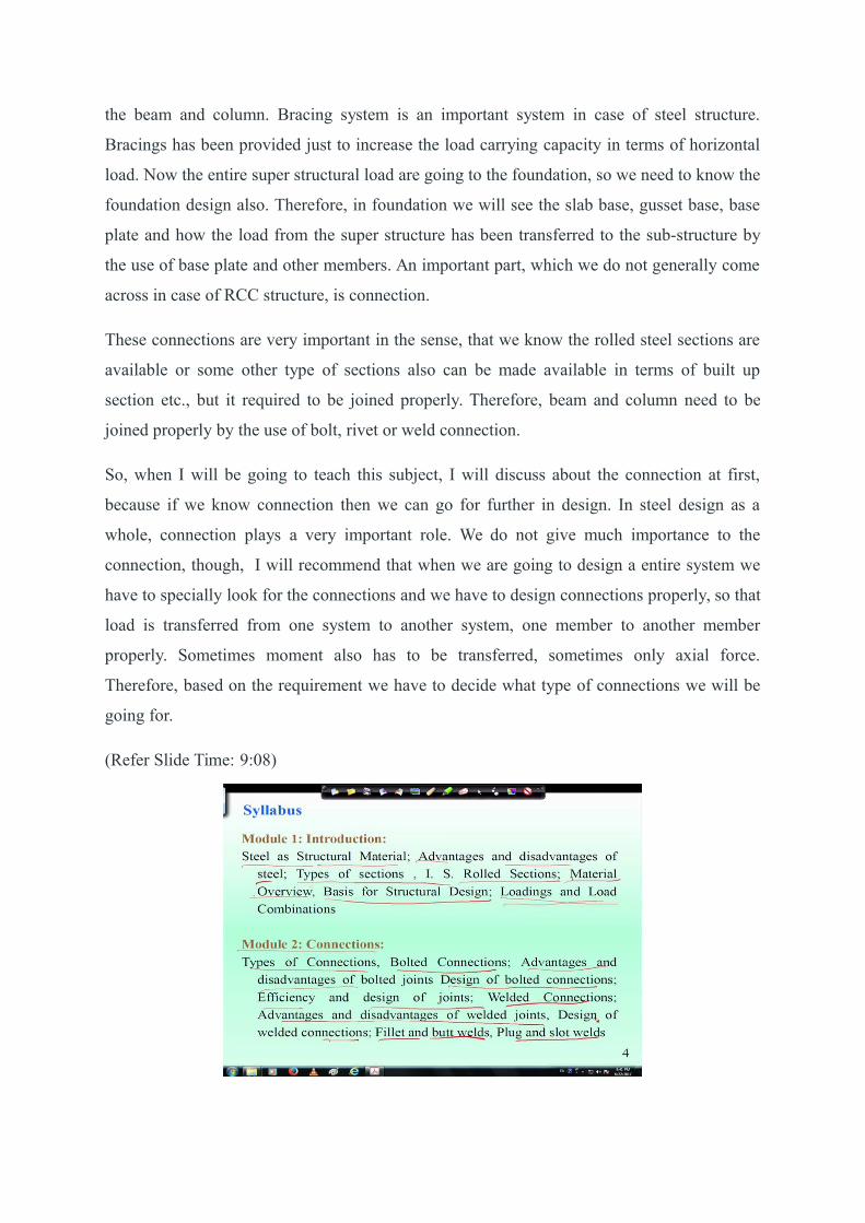
Therefore, I am briefly discussing the syllabus, which I am going to cover, but it is tentative,
because I do not know how much time I will get to finish. So first module will be
introduction, we will discuss about steel as a structural material and we will discuss its
advantages and disadvantages, because unless we know the disadvantages of steel we will not
make use of it properly. Then we will go for different types of sections, I. S. rolled sections,
which are available in the market, and their properties are given in the code. Then we will go
for some material overview, means how the steel behaves with the increase of load, how
stress strain varies in case of steel and how the mechanical properties are dependent on
chemical properties of the steel that we will discuss. Then basis for structural design will be
discussed means what type of structural design we are going for in this course.
Then we will come to the module 2, which comprises of connections. So different types of
connections will be discussed and in that connection we will discuss about the bolted
connections, its advantages and disadvantages, then design of bolted connections, its
efficiency and design of joints, then welded connections, advantages and disadvantages of
welded joints, design of weld connections, fillet weld, butt or group weld, plug and slot weld.
So these are the probable topics, I am going to cover.
(Refer Slide Time: 11:38)
Then in next module, we will discuss about the eccentric connections, because sometimes
connections become eccentric in terms of its loading. So, different types of eccentric
connections are observed, so we will discuss about bolted and welded connection with load
lying in plane of joint and load lying perpendicular to the plane of joint.

Then we will discuss about the design of eccentric connection using bolts and weld. In
module 4, we will discuss about the design of tension members. In tension member, we will
first come into different types of failures, we will find out the gross and net sectional area,
then rupture of critical section then strength calculation, block shear failure, then slenderness
ratio of the member and then we will come to design of tension members, considering all this
and then gusset plates, lug angle, tension splices, design of tension members subjected to
axial and bending, those things will be discussed
(Refer Slide Time: 13:24)
In module 5, we will discuss about the compression members. In compression member, first
we will see what are the types of failure occur in case of compression member and
accordingly the strength calculation will be discussed. Then how to calculate slenderness
ratio of the compression member, we will find out and then design of the compression
member and design of eccentrically loaded compression member that means when moment
also will come into picture.
Sometimes the rolled steel section is not sufficient for withstanding the huge amount of load.
So, in that case we will go for built-up compression member, their design procedure will be
discussed. Then in built-up compression member, we need to add the lacing systems. So
design of lacing system and design of batten plates will also be discussed in this module.
In module 6, we will discuss about the flexural member which is called beam. So we will
give you some introduction to flexural member and then design procedure of beam. Beam
will be basically two types, laterally supported beam and laterally un-supported beam, for

both the cases, design procedure will be discussed. Built-up beams and design of purlins also
will be introduced in this module.
Then we will come to column base, design of the gusseted base and slab base along with base
plate will be discussed here. If we get time then we will discuss about the gantry girder,
because in steel structure gantry girder is an important component, which we need to know.
So in last module we will discuss about the design aspects of gantry girder, various type of
loads will be there. Therefore, what are the loads coming into gantry girder and how to design
the gantry girder will be discussed.
(Refer Slide Time: 16:17)

Now I would suggest to follow these two books along with my lectures. These books are very
well written; one book is design of steel structure written by Dr. Subramanian Narayanan
who has directly involved with the development of I. S. 800 2007 code. He has written this
book which is very exhaustively written and well documented. Another book also you can
follow that is written by S. K. Duggal, Tata McGraw Hill publication, limit state design of
steel structure and the first book is published by Oxford publication.
So, other than these two books you can follow some other books also if you want, but I have
seen many books are available in which design calculations are not given properly. However,
in these two books the design calculation and procedures and very well documented in a
simplified manner. You can go for some reference also like design of steel structure by Elias
Abu-Saba, this is CBS publication, you can use this book as a reference book.
Then design of steel structure by E. H. Gaylord et al. by McGraw Hill and structural steel
work by S. S. Ray, Blackwell science. However I will suggest you to at least follow one text
book which has been suggested earlier in earlier slide that is either Dr. Subramananyn’s book
or S. K. Duggals’ book.

(Refer Slide Time: 18:15)
Now these codes are required while learning the design of steel structure, first is the earlier
code IS: 800, 1984 which was based on working this method. Now the codel provision has
been changed and in IS 800-2007, the code of practice for general construction in steel has
been given, in which the limit state design method has been followed. Therefore, when you
follow my lecture I will suggest you to sit with this code, because lot of codal provisions are
there, which has to be followed while listening my lecture. If you follow the codes at the
same time, it will be easier to understand the lecture. There is a handbook that is SP 6(1)-
1964 for structural engineers where the Indian steel rolled section properties are given.
All the standard rolled section (I section, channel section, T section, angle sections)
properties are given in that IS handbook. So we should follow that and also we can follow the
IS 808-1989 where certain properties are given. You can use steel table of any standard
publication where the properties are given. Other than that, I will suggest you to follow IS
875-part I to part IV for design loads other than earthquake for buildings and structures. I will
come with this code in details later and also IRC code vehicle load in bridge structures may
be useful apart from this for seismic consideration IS 1893-2002 .
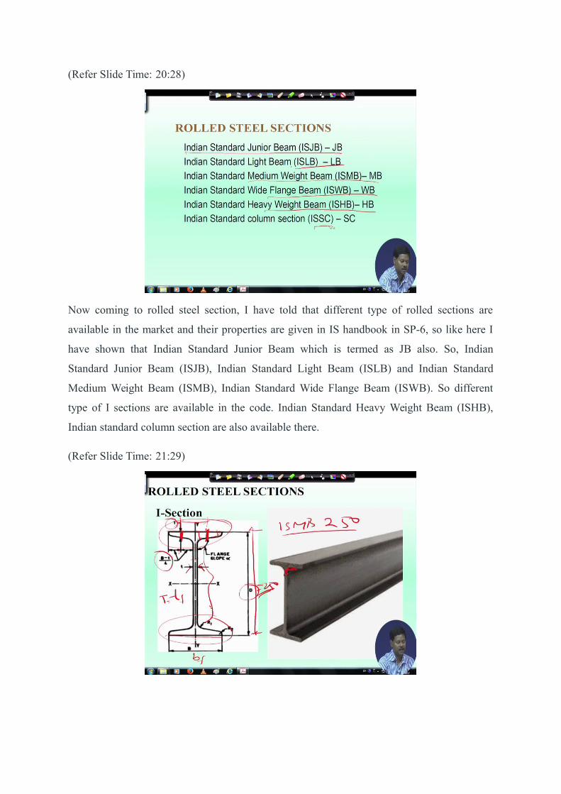
(Refer Slide Time: 20:28)
Now coming to rolled steel section, I have told that different type of rolled sections are
available in the market and their properties are given in IS handbook in SP-6, so like here I
have shown that Indian Standard Junior Beam which is termed as JB also. So, Indian
Standard Junior Beam (ISJB), Indian Standard Light Beam (ISLB) and Indian Standard
Medium Weight Beam (ISMB), Indian Standard Wide Flange Beam (ISWB). So different
type of I sections are available in the code. Indian Standard Heavy Weight Beam (ISHB),
Indian standard column section are also available there.
(Refer Slide Time: 21:29)

Now, the overall depth of I section is called D, in the SP-6, the properties of I sections are
given. If you say ISMB 250 that means it will refer to a particular I section of medium beam
ISMB, that 250 means the overall depth of the section will be 250. Therefore, this D will be
250 overall depth.
The width of flange is called B and sometimes we call bf also, and web thickness is called t or
tw. Thickness of flange is measured at (B - t)/4 distance and we mention the thickness of the
flange is T or tf.
So if you see in the SP-6, the properties of I section suppose if it is ISMB 250 then its depth
is 250, its weight, its cross sectional area and the geometrical properties everything is
mentioned there. Not only the geometrical properties, but also Ixx, (moment of inertia about x-
axis), Iyy (moment of inertia about y-axis), Rxx (radius of gyration about x-axis), Ryy (radius of
gyration about y-axis), section modulus Ze, Zp, gauge distance can be found. Therefore, that
gauge distance is also standard for particular section. So all the relevant properties can be
found out from that code.
(Refer Slide Time: 25:10)
This channel section are mainly used for column. Indian standard junior channel (ISJC),
ISLC Indian standard light channel (ISLC) Indian standard medium weight channel ISMC,
different types of channel section are available in code. Here, ISMC 400 means the overall
depth D will be 400. Once depth is known, other properties can be found out from SP-6.
The width of the flange is termed as bf and the thickness of the flange T or tf is defined at a
distance (B-t)/4, tw is the thickness of web, R1 and R2 are the radius of curvature. Then Cxx, Cyy

, flange slop, α are also given in SP-6. In the code, ZZ is written in place of XX, so Ixx is
represented by Izz.
(Refer Slide Time: 27:26)
Angle sections are of two types, one is Indian standard equal angle and another is Indian
standard unequal angle. Equal angle means leg length of both of the legs are same, but if leg
lengths are unequal then it is unequal angle. So standard way of writing is ISA 90 × 90 × 6,
that means both of the leg length is 90, thickness of the leg is 6 mm.
(Refer Slide Time: 28:23)

(Refer Slide Time: 29:26)
This is another section, which is called Tee section, Indian standard normal Tee section and in
case of Tee section, the total h is the depth.
(Refer Slide Time: 29:52)
There are rolled steel bars, which is called Indian Standard Round Section (ISRO) and this is
Indian Standard Square Section (ISSQ).

(Refer Slide Time: 30:13)
ISRO100 means it is a round section of diameter 100, again ISSQ50 means it is a square
section of each side 50 mm. So, this is how it is designated.
(Refer Slide Time: 30:42)
Then rolled steel sheet and strips are also used, those are termed as Indian Standards steel
sheet section and Indian Standard steel strip section. 50 F 8 represent a flat of width 50 mm
and thickness of 8 mm are used.
(Refer Slide Time: 31:30)

Square hollow sections and hollow pipe sections are also used in design of steel members. So
in this first lecture it is shown that different Indian rolled sections are available for designing
and their geometrical properties are given in SP-6 which will be frequently used for design of
structural members.