Embed Size (px)
Citation preview
Highway IDEA Program
Corrosion Resistant, Structurally Reinforced, Thermal Spray Coatings for In
Situ Repair of Load Bearing Structures
Final Report for
Highway IDEA Project 155
Prepared by:
Sanjay Sampath and Toshio Nakamura
Stony Brook University
November 2012

Innovations Deserving Exploratory Analysis (IDEA) Programs
Managed by the Transportation Research Board
This IDEA project was funded by the NCHRP IDEA Program.
The TRB currently manages the following three IDEA programs:
The NCHRP IDEA Program, which focuses on advances in the design, construction, and maintenance
of highway systems, is funded by American Association of State Highway and Transportation
Officials (AASHTO) as part of the National Cooperative Highway Research Program (NCHRP).
The Safety IDEA Program currently focuses on innovative approaches for improving railroad safety
or performance. The program is currently funded by the Federal Railroad Administration (FRA).
The program was previously jointly funded by the Federal Motor Carrier Safety Administration
(FMCSA) and the FRA.
The Transit IDEA Program, which supports development and testing of innovative concepts and
methods for advancing transit practice, is funded by the Federal Transit Administration (FTA) as part
of the Transit Cooperative Research Program (TCRP).
Management of the three IDEA programs is coordinated to promote the development and testing of
innovative concepts, methods, and technologies.
For information on the IDEA programs, check the IDEA website (www.trb.org/idea). For questions,
contact the IDEA programs office by telephone at (202) 334-3310.
IDEA Programs
Transportation Research Board
500 Fifth Street, NW
Washington, DC 20001
“Corrosion Resistant, Structurally Reinforced, Thermal Spray Coatings for In
Situ Repair of Load Bearing Structures”
Project NCHRP-155
Final Report
November, 2012
Sanjay Sampath
Toshio Nakamura
Stony Brook University
Center for Thermal Spray Research
130 Heavy Engineering Building
Stony Brook, NY 11794-2275
NCHRP IDEA PROGRAM COMMITTEE CHAIR SANDRA Q. LARSON
Iowa DOT
MEMBERS
DUANE BRAUTIGAM
Florida DOT
ANNE ELLIS
Arizona DOT
GARY A. FREDERICK
New York State DOT
GEORGENE GEARY
Georgia DOT
JOE MAHONEY
University of Washington
MAGDY MIKHAIL
Texas DOT
MICHAEL MILES
California DOT
TOMMY NANTUNG
Indiana DOT
VALERIE SHUMAN
Shuman Consulting Group LLC
JAMES SIME
Connecticut DOT (Retired)
L. DAVID SUITS
North American Geosynthetics Society
FHWA LIAISON DAVID KUEHN
Federal Highway Administration
TRB LIAISON RICHARD CUNARD
Transportation Research Board
COOPERATIVE RESEARCH PROGRAM STAFF CRAWFORD F. JENCKS
Deputy Director, Cooperative Research Programs
IDEA PROGRAMS STAFF
STEPHEN R. GODWIN
Director for Studies and Special Programs
JON M. WILLIAMS
Program Director, IDEA and Synthesis Studies
INAM JAWED
Senior Program Officer
DEMISHA WILLIAMS
Senior Program Assistant
EXPERT REVIEW PANEL
GARY FREDERICK, NY State DOT
RICHARD CAUSIN, NY State DOT
KRIS KITCHEN, Nooter Corporation
RICHARD SCHMID, Sulzer Metco Management, Inc.
1
Table of Contents
Table of Contents…….................................................................................................................... 1
Executive Summary........................................................................................................................ 2
HVOF Thermal Spray Process........................................................................................................ 3
Uniaxial Tensile Testing................................................................................................................. 5
HVOF Sprayed Fe- and Ni-Based Coatings................................................................................... 6
Corrosion Properties....................................................................................................................... 8
Modified HVOF Sprayed Ni Coatings........................................................................................... 9
Tensile Tests of Coated Specimens.............................................................................................. 11
Computational Analysis of Coated Specimens............................................................................. 19
Conclusions .................................................................................................................................. 24
References .................................................................................................................................... 27
2
1. Executive Summary
This project is developing and laying the groundwork for in-situ reclamation of corroded
components in load bearing infrastructures (e.g., bridges) imparting robust corrosion protection
using high-velocity thermal spray. This novel approach may provide interim or even potentially
long term solution to material loss and continued degradation of certain infrastructure
components and provide the Department of Transportation a new tool in infrastructure
maintenance.
The project was initiated in February 2011 and optimization for high-velocity oxy-fuel (HVOF)
processing has begun to determine the parameters necessary to produce a fill coating with
residual compressive stresses. In addition, steel dog bone tensile test bars have been acquired.
The gauge section has been reduced in thickness allowing for buildup of the gauge with HVOF-
sprayed material. In the second quarter, exploration of both Fe- and Ni-based powders occurred
to determine how high velocity oxy-fuel (HVOF) processing can be used to impart compressive
stresses in the surface of reclaimed structures.
During the 1st year, detail comparisons between Fe and Ni coatings were made. At thin coatings,
the Ni deposited ones presented a better performance compared to the Fe-based ones, since they
were able to endure excessive loads and displacements without delamination. However, both
coatings presented an increased load bearing capacity compared to virgins –uncoated- tensile test
specimens. At thick coatings, new spraying parameters were required in order to produce more
compressive coatings, as they were showing premature failure. The new compressive Ni coatings
presented the highest load bearing capacities, compared to all coatings and virgin tensile
specimens. During the fourth quarter, a new design of virgin, un-grooved, tensile test specimens
(dogbones) was introduced. The new design was adopted to serve two purposes. First, to address
weaknesses found in the grooved specimens design and second to investigate the potential of
raising the initial load bearing ability of the tensile test specimens by depositing additional
compressed material. Besides the substrate influence, new coating materials, process parameters,
and fixtures were tested, in order to elucidate the interaction mechanisms between coating and
substrate.
During the final two quarters, extensive experimental analysis was conducted including
specimen geometry material type, testing and characterization. These results allowed further
improvement in process parameters to enhance the reclaimed material properties. Computational
models were also refined to closely follow the experimental tests. In the simulations,
Concentrations of stress and deformation in coated specimens were identified and the effects of
coating area were quantified in the analysis. These studies are valuable in understanding possible
delamination (between coating and base metal) behavior. In summary, the results to date are very
encouraging suggesting that this approach could offer solutions for critical DoT applications. In
fact interest has already been generated from commercial bridge restorers and more notably from
chemical plants where the effects of corrosion on structure are far more severe. Issues of
scalability, cost and life cycle benefit assessment will need to be considered for full exploitation
of the IDEA results. The team is actively seeking funding to take the next steps. Our industrial
partners through the consortium have also been engaged in this development to ensure success.
3
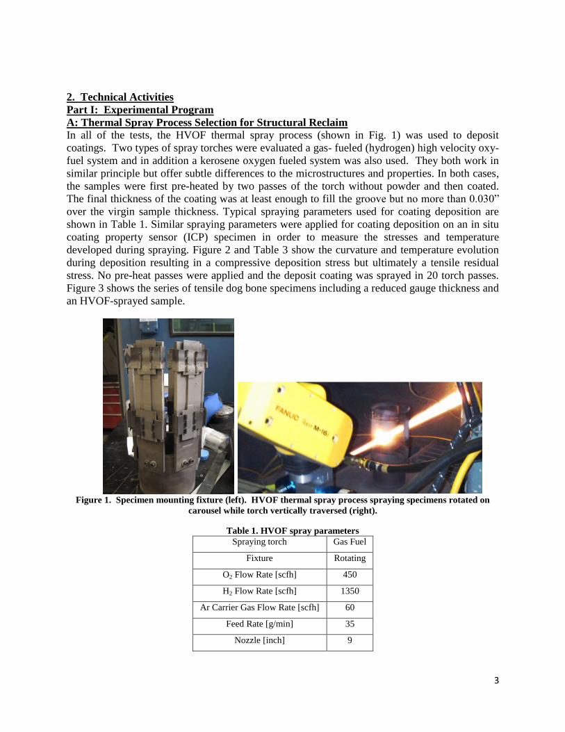
2. Technical Activities
Part I: Experimental Program
A: Thermal Spray Process Selection for Structural Reclaim
In all of the tests, the HVOF thermal spray process (shown in Fig. 1) was used to deposit
coatings. Two types of spray torches were evaluated a gas- fueled (hydrogen) high velocity oxy-
fuel system and in addition a kerosene oxygen fueled system was also used. They both work in
similar principle but offer subtle differences to the microstructures and properties. In both cases,
the samples were first pre-heated by two passes of the torch without powder and then coated.
The final thickness of the coating was at least enough to fill the groove but no more than 0.030”
over the virgin sample thickness. Typical spraying parameters used for coating deposition are
shown in Table 1. Similar spraying parameters were applied for coating deposition on an in situ
coating property sensor (ICP) specimen in order to measure the stresses and temperature
developed during spraying. Figure 2 and Table 3 show the curvature and temperature evolution
during deposition resulting in a compressive deposition stress but ultimately a tensile residual
stress. No pre-heat passes were applied and the deposit coating was sprayed in 20 torch passes.
Figure 3 shows the series of tensile dog bone specimens including a reduced gauge thickness and
an HVOF-sprayed sample.
Figure 1. Specimen mounting fixture (left). HVOF thermal spray process spraying specimens rotated on
carousel while torch vertically traversed (right).
Table 1. HVOF spray parameters
Spraying torch Gas Fuel
Fixture Rotating
O2 Flow Rate [scfh] 450
H2 Flow Rate [scfh] 1350
Ar Carrier Gas Flow Rate [scfh] 60
Feed Rate [g/min] 35
Nozzle [inch] 9
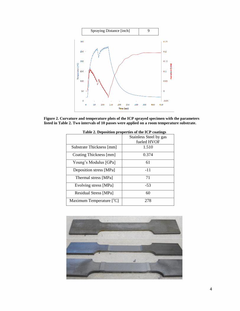
4
Spraying Distance [inch] 9
Figure 2. Curvature and temperature plots of the ICP sprayed specimen with the parameters
listed in Table 2. Two intervals of 10 passes were applied on a room temperature substrate.
Table 2. Deposition properties of the ICP coatings
Stainless Steel by gas
fueled HVOF
Substrate Thickness [mm] 1.510
Coating Thickness [mm] 0.374
Young’s Modulus [GPa] 61
Deposition stress [MPa] -11
Thermal stress [MPa] 71
Evolving stress [MPa] -53
Residual Stress [MPa] 60
Maximum Temperature [oC] 278

5
Figure 3. Tensile specimens (top: virgin sample, middle: 0.032” grooved, bottom: 0.032” grooved and coated).
B: Uniaxial Tensile Testing of Virgin and Grooved Samples
To investigate the mechanical responses of coated specimens, the tensile testing rig (Instron)
shown in Figure 4 was used. In all tests, the displacement rate of the tensile machine was set to
0.1 mm/s and allowed to run until the specimen failed.
Figure 4. Tensile testing rig with sample in place.
From the test of the virgin tensile specimen, the maximum allowable load was found to be
~31.3kN. The virgin specimen fractured near the beginning of the gauge length. Set one of
grooved and uncoated specimens showed a lower allowable force, ~22.5kN. All of the uncoated
specimens failed at the beginning of the gauge length. Shown in Figure 5 are the force vs.
displacement plots and images of the typical specimens.
Figure 5. Force-Displacement curve of virgin specimen and set one grooved specimens (left). Image of
fractured specimens after testing (right).
6
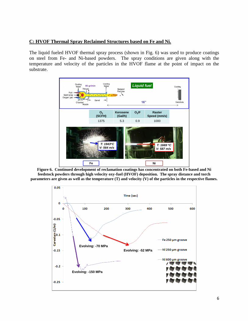
C: HVOF Thermal Spray Reclaimed Structures based on Fe and Ni.
The liquid fueled HVOF thermal spray process (shown in Fig. 6) was used to produce coatings
on steel from Fe- and Ni-based powders. The spray conditions are given along with the
temperature and velocity of the particles in the HVOF flame at the point of impact on the
substrate.
Liquid fuel
16’’
O2
(SCFH)
Kerosene
(Gal/h)
O2/F Raster
Speed (mm/s)
1375 5.3 0.9 1000
80 gr/min
Fe Ni
T: 1943oC
V: 564 m/s T: 1669 oC
V: 587 m/s
Figure 6. Continued development of reclamation coatings has concentrated on both Fe-based and Ni
feedstock powders through high velocity oxy-fuel (HVOF) deposition. The spray distance and torch
parameters are given as well as the temperature (T) and velocity (V) of the particles in the respective flames.
Evolving: -52 MPa
Evolving: -70 MPa
Evolving: -150 MPa
7
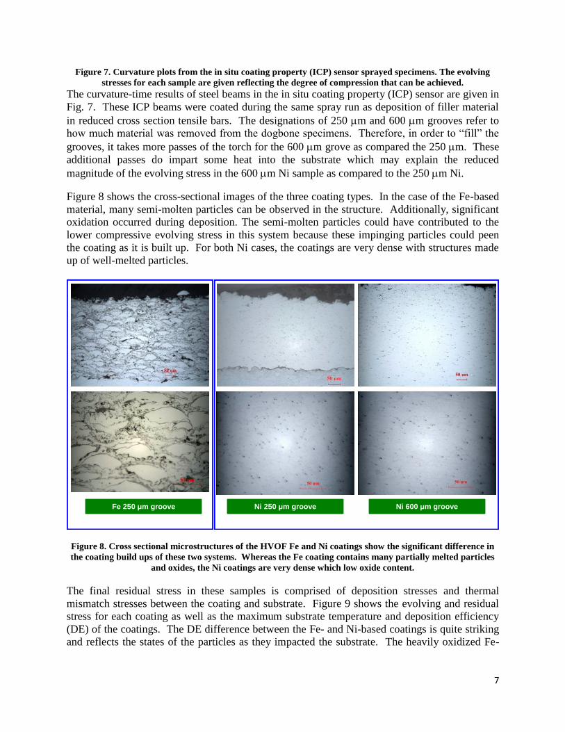
Figure 7. Curvature plots from the in situ coating property (ICP) sensor sprayed specimens. The evolving
stresses for each sample are given reflecting the degree of compression that can be achieved.
The curvature-time results of steel beams in the in situ coating property (ICP) sensor are given in
Fig. 7. These ICP beams were coated during the same spray run as deposition of filler material
in reduced cross section tensile bars. The designations of 250 m and 600 m grooves refer to
how much material was removed from the dogbone specimens. Therefore, in order to “fill” the
grooves, it takes more passes of the torch for the 600 m grove as compared the 250 m. These
additional passes do impart some heat into the substrate which may explain the reduced
magnitude of the evolving stress in the 600 m Ni sample as compared to the 250 m Ni.
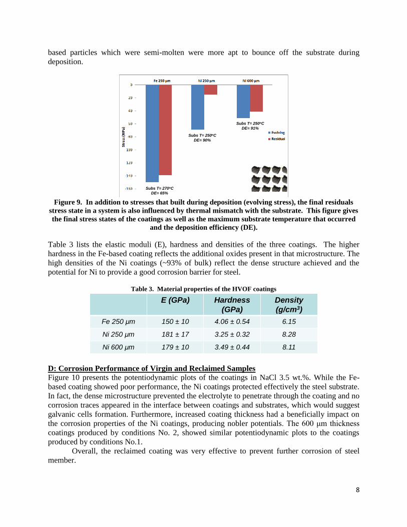
Figure 8 shows the cross-sectional images of the three coating types. In the case of the Fe-based
material, many semi-molten particles can be observed in the structure. Additionally, significant
oxidation occurred during deposition. The semi-molten particles could have contributed to the
lower compressive evolving stress in this system because these impinging particles could peen
the coating as it is built up. For both Ni cases, the coatings are very dense with structures made
up of well-melted particles.
Fe 250 μm groove Ni 600 μm grooveNi 250 μm groove
Figure 8. Cross sectional microstructures of the HVOF Fe and Ni coatings show the significant difference in
the coating build ups of these two systems. Whereas the Fe coating contains many partially melted particles
and oxides, the Ni coatings are very dense which low oxide content.
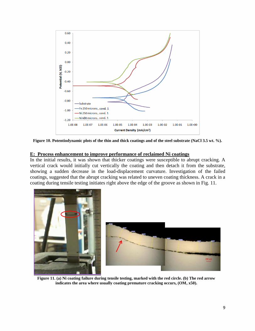
The final residual stress in these samples is comprised of deposition stresses and thermal
mismatch stresses between the coating and substrate. Figure 9 shows the evolving and residual
stress for each coating as well as the maximum substrate temperature and deposition efficiency
(DE) of the coatings. The DE difference between the Fe- and Ni-based coatings is quite striking
and reflects the states of the particles as they impacted the substrate. The heavily oxidized Fe-
8
based particles which were semi-molten were more apt to bounce off the substrate during
deposition.
Subs T= 270oC
DE= 65%
Subs T= 250oC
DE= 90%
Subs T= 250oC
DE= 91%
Figure 9. In addition to stresses that built during deposition (evolving stress), the final residuals
stress state in a system is also influenced by thermal mismatch with the substrate. This figure gives
the final stress states of the coatings as well as the maximum substrate temperature that occurred
and the deposition efficiency (DE).
Table 3 lists the elastic moduli (E), hardness and densities of the three coatings. The higher
hardness in the Fe-based coating reflects the additional oxides present in that microstructure. The
high densities of the Ni coatings (~93% of bulk) reflect the dense structure achieved and the
potential for Ni to provide a good corrosion barrier for steel.
Table 3. Material properties of the HVOF coatings
E (GPa) Hardness
(GPa)
Density
(g/cm3)
Fe 250 μm 150 ± 10 4.06 ± 0.54 6.15
Ni 250 μm 181 ± 17 3.25 ± 0.32 8.28
Ni 600 μm 179 ± 10 3.49 ± 0.44 8.11
D: Corrosion Performance of Virgin and Reclaimed Samples
Figure 10 presents the potentiodynamic plots of the coatings in NaCl 3.5 wt.%. While the Fe-
based coating showed poor performance, the Ni coatings protected effectively the steel substrate.
In fact, the dense microstructure prevented the electrolyte to penetrate through the coating and no
corrosion traces appeared in the interface between coatings and substrates, which would suggest
galvanic cells formation. Furthermore, increased coating thickness had a beneficially impact on
the corrosion properties of the Ni coatings, producing nobler potentials. The 600 μm thickness
coatings produced by conditions No. 2, showed similar potentiodynamic plots to the coatings
produced by conditions No.1.
Overall, the reclaimed coating was very effective to prevent further corrosion of steel
member.
9
Figure 11. (a) Ni coating failure during tensile testing, marked with the red circle. (b) The red arrow
indicates the area where usually coating premature cracking occurs, (OM, x50).
Figure 10. Potentiodynamic plots of the thin and thick coatings and of the steel substrate (NaCl 3.5 wt. %).
E: Process enhancement to improve performance of reclaimed Ni coatings In the initial results, it was shown that thicker coatings were susceptible to abrupt cracking. A
vertical crack would initially cut vertically the coating and then detach it from the substrate,
showing a sudden decrease in the load-displacement curvature. Investigation of the failed
coatings, suggested that the abrupt cracking was related to uneven coating thickness. A crack in a
coating during tensile testing initiates right above the edge of the groove as shown in Fig. 11.
10
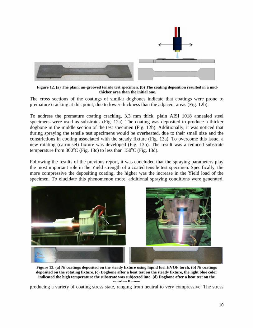
The cross sections of the coatings of similar dogbones indicate that coatings were prone to
premature cracking at this point, due to lower thickness than the adjacent areas (Fig. 12b).
To address the premature coating cracking, 3.3 mm thick, plain AISI 1018 annealed steel
specimens were used as substrates (Fig. 12a). The coating was deposited to produce a thicker
dogbone in the middle section of the test specimen (Fig. 12b). Additionally, it was noticed that
during spraying the tensile test specimens would be overheated, due to their small size and the
constrictions in cooling associated with the steady fixture (Fig. 13a). To overcome this issue, a
new rotating (carrousel) fixture was developed (Fig. 13b). The result was a reduced substrate
temperature from 300oC (Fig. 13c) to less than 150
oC (Fig. 13d).
Following the results of the previous report, it was concluded that the spraying parameters play
the most important role in the Yield strength of a coated tensile test specimen. Specifically, the
more compressive the depositing coating, the higher was the increase in the Yield load of the
specimen. To elucidate this phenomenon more, additional spraying conditions were generated,
producing a variety of coating stress state, ranging from neutral to very compressive. The stress
Figure 12. (a) The plain, un-grooved tensile test specimen. (b) The coating deposition resulted in a mid-
thicker area than the initial one.
Figure 13. (a) Ni coatings deposited on the steady fixture using liquid fuel HVOF torch. (b) Ni coatings
deposited on the rotating fixture. (c) Dogbone after a heat test on the steady fixture, the light blue color
indicated the high temperature the substrate was subjected into. (d) Dogbone after a heat test on the
rotating fixture.
11
state produced during each spraying condition, along with the measured particle velocity and
surface temperature, measured by the Accuraspray sensor (Tecnar, Canada) are listed in Table 4.
Table 4. Coating evolving stress state as indicated by deposition on an ICP sensor.
(Spraying distance: 16 in, powder: Ni, powder feed rate: 80 gr/min)
Coating stress
state
Mean Velocity
(m/s)
Mean
Temperature
(oC)
c04 Compressive 659 1639
c09 Slightly
compressive 587 1669
c10 Neutral 560 1638
c11 Very
Compressive 676 1648
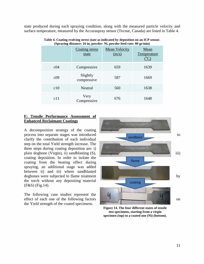
F: Tensile Performance Assessment of
Enhanced Reclaimant Coatings
A decomposition strategy of the coating
process into separate stages was introduced to
clarify the contribution of each individual
step on the total Yield strength increase. The
three steps during coating deposition are: i)
plain dogbone (Virgin), ii) sandblasting (S), iii)
coating deposition. In order to isolate the
coating from the heating effect during
spraying, an additional stage was added
between ii) and iii) where sandblasted
dogbones were subjected to flame treatment by
the torch without any depositing material
(F&S) (Fig.14).
The following case studies represent the
effect of each one of the following factors on
the Yield strength of the coated specimens.
sandblast
flame
coating
Figure 14. The four different states of tensile
test specimens, starting from a virgin
specimen (top) to a coated one (Ni) (bottom).

12
Effects of Coating Materials
Fig. 15 is indicative of the increasing load bearing ability of the tensile test specimens at the
consecutive stages of substrate preparation and coating deposition. In this case, different coatings
(Cu and Ni) of similar thickness (250 μm) were deposited under the same torch parameters (c04)
on the steady dogbones fixture. It is evident that, while the sandblasting stage did not induce any
significant change in the Yield point of the specimens, the third stage (F&S) increased the Yield
point by approximately 13% compared to the virgin correspondent. Finally, the application of
different coatings seemed to influence the overall performance with nickel demonstrating a
higher load bearing ability.
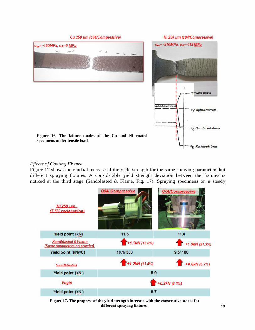
Figure 16 is indicative of the failure that occurred in the dogbones of Fig. 15. While the Cu
deposited specimen failed inside the coated area, the Ni deposited specimen failed in the
uncoated area adjacent to the coated one. As it is shown, the residual stress (R) of the Ni coating
was more compressive than the Cu’s correspondent. During Ni spraying, it is anticipated also
that the substrate surface and sub-superficial layers are under compressive stress as the first
particles impact on them. As Fig. 16 shows, that resulted in a stress gradient formation in the
substrate between the coated and adjacent uncoated area. As additional tensile stress was
imposed during testing, the combined (residual and applied) stress of the uncoated area exceeded
the Ultimate Tensile Stress (UTS) of the steel and failed first. The absence of compressive
residual stress in the Cu case prevented the substrate stress gradient from occurring.
Figure 15. The progress of the yield strength changes with the consecutive stages for different
materials (starting from the bottom).
13
Effects of Coating Fixture
Figure 17 shows the gradual increase of the yield strength for the same spraying parameters but
different spraying fixtures. A considerable yield strength deviation between the fixtures is
noticed at the third stage (Sandblasted & Flame, Fig. 17). Spraying specimens on a steady
Figure 16. The failure modes of the Cu and Ni coated
specimens under tensile load.
Figure 17. The progress of the yield strength increase with the consecutive stages for
different spraying fixtures.
14
fixtures results in a higher substrate temperature, which raises the yield point, whereas a lower
substrate temperature comes with a less increased yield point. The coating addition in the last
stage seems to produce similar results for both fixtures. It is noticeable that the load-
displacement plots for virgin and only sandblasted specimens, (Fig. 14) coincide, suggesting a
minor impact due to steel work hardening induced by sandblasting (Fig. 18).
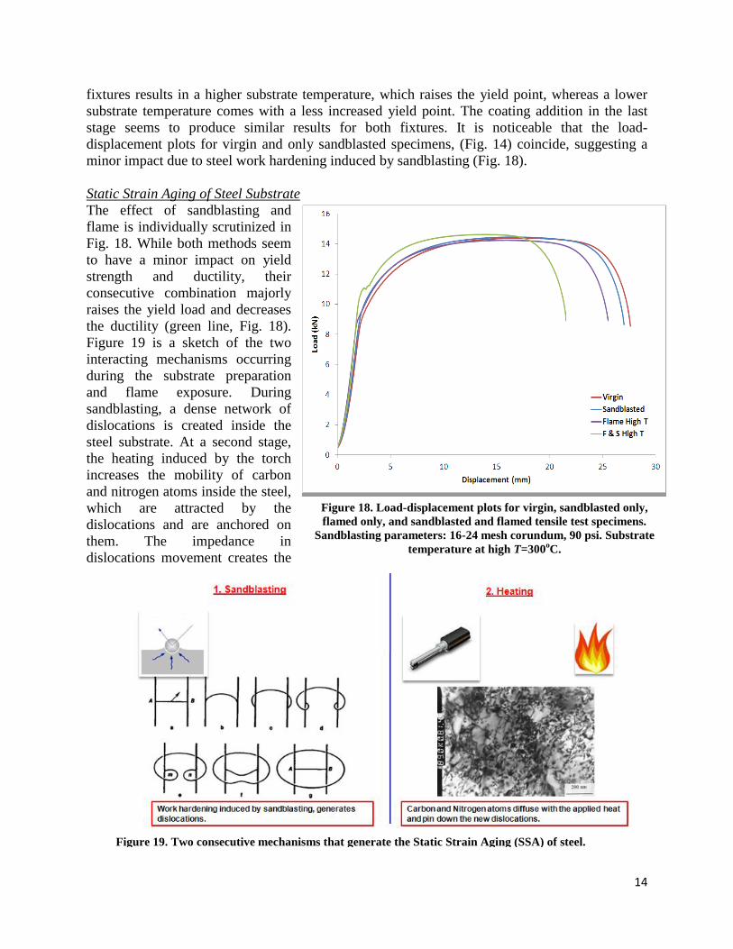
Static Strain Aging of Steel Substrate
The effect of sandblasting and
flame is individually scrutinized in
Fig. 18. While both methods seem
to have a minor impact on yield
strength and ductility, their
consecutive combination majorly
raises the yield load and decreases
the ductility (green line, Fig. 18).
Figure 19 is a sketch of the two
interacting mechanisms occurring
during the substrate preparation
and flame exposure. During
sandblasting, a dense network of
dislocations is created inside the
steel substrate. At a second stage,
the heating induced by the torch
increases the mobility of carbon
and nitrogen atoms inside the steel,
which are attracted by the
dislocations and are anchored on
them. The impedance in
dislocations movement creates the
Figure 18. Load-displacement plots for virgin, sandblasted only,
flamed only, and sandblasted and flamed tensile test specimens.
Sandblasting parameters: 16-24 mesh corundum, 90 psi. Substrate
temperature at high T=300oC.
Figure 19. Two consecutive mechanisms that generate the Static Strain Aging (SSA) of steel.
15
increased Yield strength. It is conceivable that higher or extended heat will mobilize more atoms
and anchor more dislocations, resulting in an increased Yield strength. This phenomenon is
reported in literature as Static Strain Aging (SSA) [1, 2].
However, beyond the raised yield strength, the sand/grit-blasted and flamed specimens
demonstrated decreased ductility. That can be explained through the representative sketch in Fig.
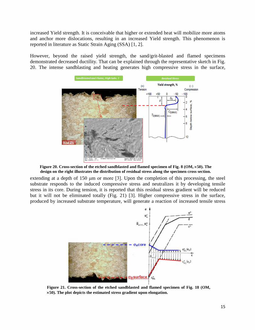
20. The intense sandblasting and heating generates high compressive stress in the surface,
extending at a depth of 150 μm or more [3]. Upon the completion of this processing, the steel
substrate responds to the induced compressive stress and neutralizes it by developing tensile
stress in its core. During tension, it is reported that this residual stress gradient will be reduced
but it will not be eliminated totally (Fig. 21) [3]. Higher compressive stress in the surface,
produced by increased substrate temperature, will generate a reaction of increased tensile stress
Figure 20. Cross-section of the etched sandblasted and flamed specimen of Fig. 8 (OM, 50). The
design on the right illustrates the distribution of residual stress along the specimen cross section.
Figure 21. Cross-section of the etched sandblasted and flamed specimen of Fig. 18 (OM,
50). The plot depicts the estimated stress gradient upon elongation.
16
in the interior of the steel, resulting in premature failure during elongation, thus reduced
ductility.
Effects of Torch Parameters
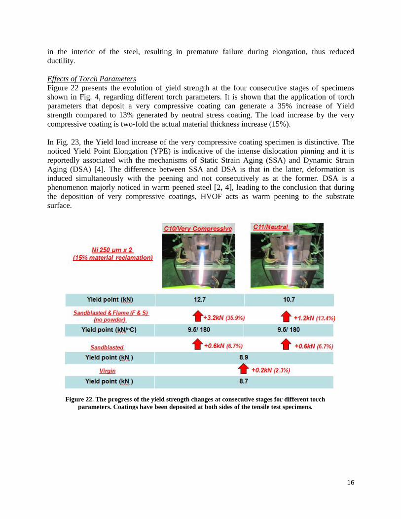
Figure 22 presents the evolution of yield strength at the four consecutive stages of specimens
shown in Fig. 4, regarding different torch parameters. It is shown that the application of torch
parameters that deposit a very compressive coating can generate a 35% increase of Yield
strength compared to 13% generated by neutral stress coating. The load increase by the very
compressive coating is two-fold the actual material thickness increase (15%).
In Fig. 23, the Yield load increase of the very compressive coating specimen is distinctive. The
noticed Yield Point Elongation (YPE) is indicative of the intense dislocation pinning and it is
reportedly associated with the mechanisms of Static Strain Aging (SSA) and Dynamic Strain
Aging (DSA) [4]. The difference between SSA and DSA is that in the latter, deformation is
induced simultaneously with the peening and not consecutively as at the former. DSA is a
phenomenon majorly noticed in warm peened steel [2, 4], leading to the conclusion that during
the deposition of very compressive coatings, HVOF acts as warm peening to the substrate
surface.
Figure 22. The progress of the yield strength changes at consecutive stages for different torch
parameters. Coatings have been deposited at both sides of the tensile test specimens.

17
Effects of Coating Thickness
Figure 24 shows the impact of depositing different coating thickness under the same spraying
parameters, fixture and material. It is shown that thicker coatings can increase the load bearing
ability up to a certain degree.
Figure 23. Load-displacement plots for virgin, sandblasted and flamed at low temperature, neutral and
very compressive Ni coated specimens.
Figure 24. The progress of the yield strength increase with the consecutive stages for different coatings
thicknesses. Coatings have been deposited at both sides of the tensile test specimens.
18
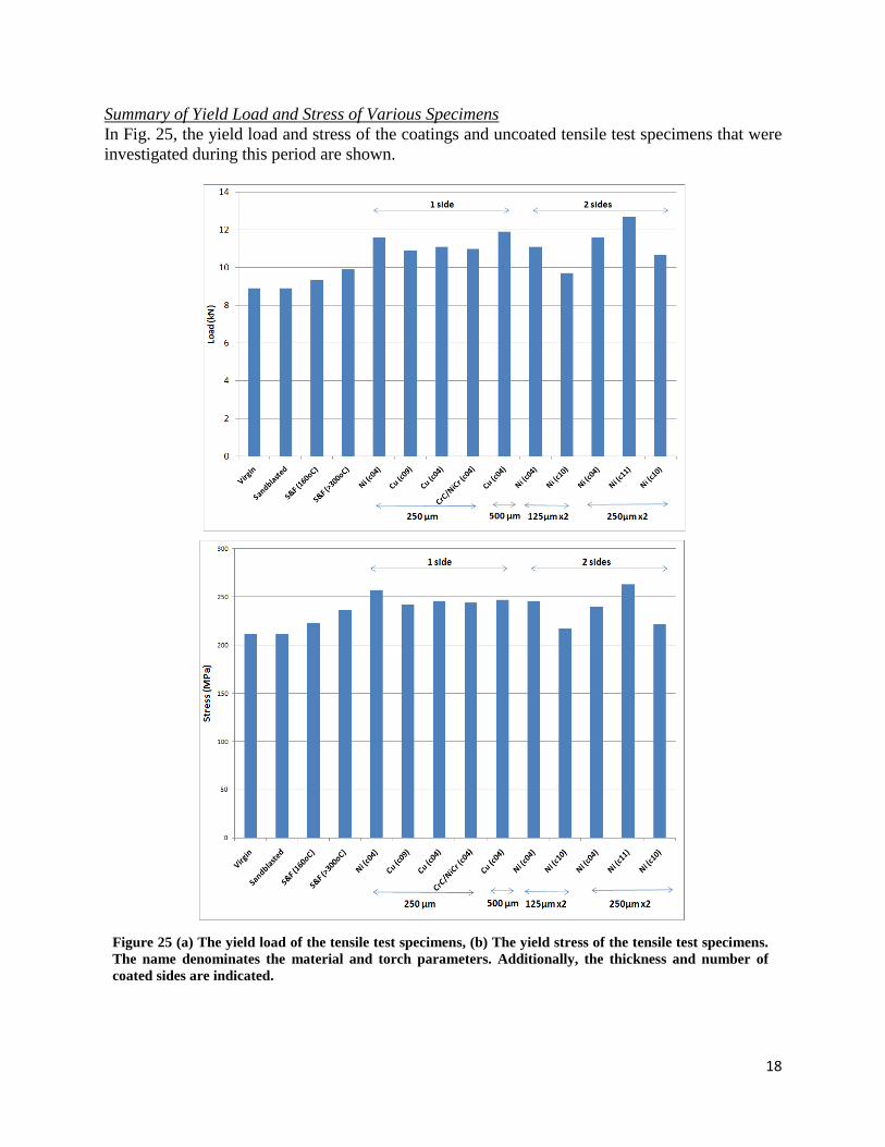
Summary of Yield Load and Stress of Various Specimens
In Fig. 25, the yield load and stress of the coatings and uncoated tensile test specimens that were
investigated during this period are shown.
Figure 25 (a) The yield load of the tensile test specimens, (b) The yield stress of the tensile test specimens.
The name denominates the material and torch parameters. Additionally, the thickness and number of
coated sides are indicated.

19
Part II: Computational Analysis of Coated Specimens
Detailed model were made in the finite element analysis to probe and elucidate the load carrying
mechanisms within the coated specimens. A major change is made on the modeling of material
properties for the substrate steel and the thermal sprayed Ni coatings. The new stress-strain
relation of steel substrate properly includes the static strain gaining effects. The simulations
elucidate load transfer mechanisms that are otherwise not apparent in the experimental
investigations
Material Models
As described in the earlier section, we have determined stiffening behavior of steel when it is
subjected to grit-blasting and high temperature due to the mechanism known static strain aging.
Using the tensile testing of steel specimens without coatings but exposed to grit-blasting and
high-heat, a new elastic-plastic property of substrate was identified as shown in Fig. 26. The
proper stress-strain relation of HVOF Ni coating was also determined from the simulations. Here
a few iterations were carried out to best match the tensile load test results of Ni coated specimen
as shown in Fig. 17. The Young’s modulus of E = 150GPa and the yield stress of o = 350MPa
Displacement [mm]
Experiment
Lo
ad
[kN
]
Simulation
0 0.2 0.4 0.6 0
5
10
15
Steel substrate
E = 205GPa
= 0.3
Y = 251 MPa
UTS
= 365 MPa
Strain
Str
ess [
MP
a]
0.000 0.005 0.010 0.015 0.020 0
100
200
300
400
500
Fig. 16. Elastic-plastic stress-strain relation of steel substrate was determined by matching the
uniaxial tensile test of uncoated specimen.

20
Material Models
As described in the earlier section, we have determined stiffening behavior of steel when it is
subjected to grit-blasting and high temperature due to the mechanism known static strain aging.
Using the tensile testing of steel specimens without coatings but exposed to grit-blasting and
high-heat, a new elastic-plastic property of substrate was identified as shown in Fig. 16. The
proper stress-strain relation of HVOF Ni coating was also determined from the simulations. Here
a few iterations were carried out to best match the tensile load test results of Ni coated specimen
as shown in Fig. 17. The Young’s modulus of E = 150GPa and the yield stress of o = 350MPa
Displacement [mm]
Experiment
Lo
ad
[kN
]
Simulation
0 0.2 0.4 0.6 0
5
10
15
Steel substrate
E = 205 GPa
= 0.3
Y = 251 MPa
UTS
= 365 MPa
Strain
Str
ess [
MP
a]
0.000 0.005 0.010 0.015 0.020 0
100
200
300
400
500
Figure 26. Elastic-plastic stress-strain relation of steel substrate was determined by matching the uniaxial tensile
test of uncoated specimen.
0 0.0 0.2 0.4
0
Str
ess [
MP
a]
Steel
Ni coatings Y= 350 MPa
Strain 0.000 0.005 0.010 0.015 0.020
0
100
200
300
400
Figure 27. Elastic-perfectly plastic stress-strain relation is assumed for TS Ni coating. The yield stress is
determined from matching the tensile test of coated specimen.
500
5
10
15
Lo
ad
[kN
]
Displacement [mm]
21
were identified after a few iterations of
tensile test simulations. The resulting
load-displacement curve match very well
with the experimental data.
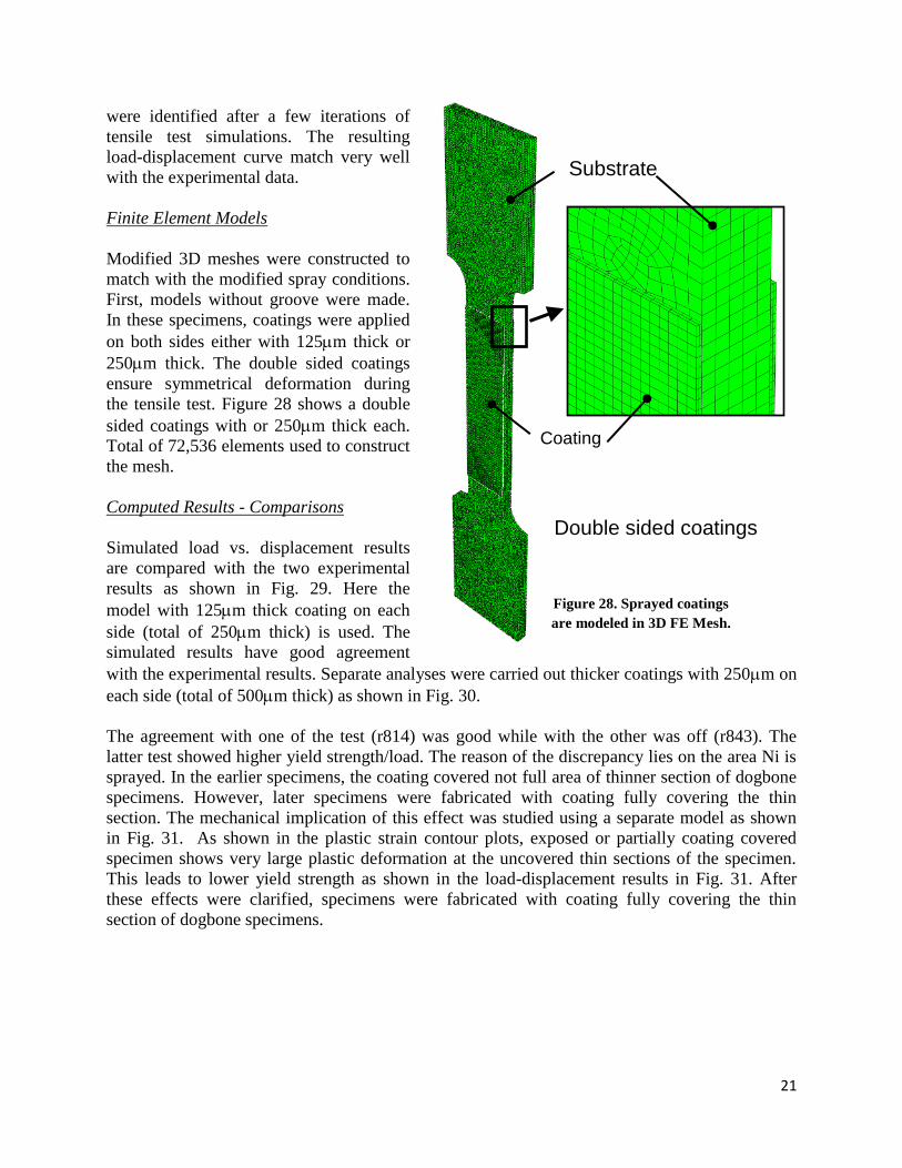
Finite Element Models
Modified 3D meshes were constructed to
match with the modified spray conditions.
First, models without groove were made.
In these specimens, coatings were applied
on both sides either with 125m thick or
250m thick. The double sided coatings
ensure symmetrical deformation during
the tensile test. Figure 28 shows a double
sided coatings with or 250m thick each.
Total of 72,536 elements used to construct
the mesh.
Computed Results - Comparisons
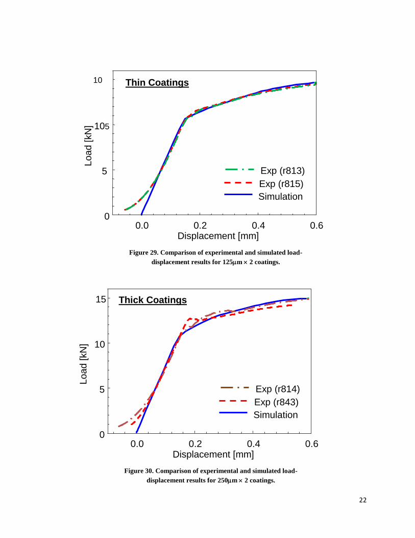
Simulated load vs. displacement results
are compared with the two experimental
results as shown in Fig. 29. Here the
model with 125m thick coating on each
side (total of 250m thick) is used. The
simulated results have good agreement
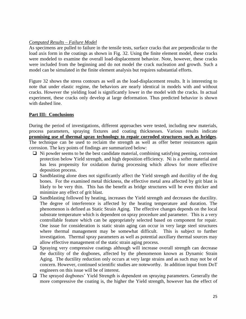
with the experimental results. Separate analyses were carried out thicker coatings with 250m on
each side (total of 500m thick) as shown in Fig. 30.
The agreement with one of the test (r814) was good while with the other was off (r843). The
latter test showed higher yield strength/load. The reason of the discrepancy lies on the area Ni is
sprayed. In the earlier specimens, the coating covered not full area of thinner section of dogbone
specimens. However, later specimens were fabricated with coating fully covering the thin
section. The mechanical implication of this effect was studied using a separate model as shown
in Fig. 31. As shown in the plastic strain contour plots, exposed or partially coating covered
specimen shows very large plastic deformation at the uncovered thin sections of the specimen.
This leads to lower yield strength as shown in the load-displacement results in Fig. 31. After
these effects were clarified, specimens were fabricated with coating fully covering the thin
section of dogbone specimens.
Substrate
Coating
Double sided coatings
Figure 28. Sprayed coatings
are modeled in 3D FE Mesh.
22
Displacement [mm]
Lo
ad
[kN
]
0.0 0.2 0.4 0.6 0
5
105
10
Simulation
Exp (r815)
Exp (r813)
Figure 29. Comparison of experimental and simulated load-
displacement results for 125m 2 coatings.
Thin Coatings
Displacement [mm]
Lo
ad
[kN
]
0.0 0.2 0.4 0.6 0
5
10
Simulation
Exp (r843)
Exp (r814)
Figure 30. Comparison of experimental and simulated load-
displacement results for 250m 2 coatings.
15
Thick Coatings

23

24
Figure 31. Comparisons of coatings fully covering thin section and
coatings exposing ends of thin section are shown. In the latter,
large deformation develops in the exposed sections.
Fully covered coatings
Exposed coatings
Exposed coatings
Fully covered coatings
0.0 0.2 0.4 0.6 0.8
5
10
15
20
Displacement [mm]
Lo
ad
[kN
Figure 32. Simulations of surface cracked coating. These cracks not only lower the maximum
tensile load and generate stress concentration in the substrate.
Lo
ad
[kN
]
Displacement [mm]
Cracked model
Uncracked model
0 0.1 0.2 0.4 0.6 0.8 1.0
0
2
4
6
8
10
12
Estimated combined behavior
25
Computed Results – Failure Model
As specimens are pulled to failure in the tensile tests, surface cracks that are perpendicular to the
load axis form in the coatings as shown in Fig. 32. Using the finite element model, these cracks
were modeled to examine the overall load-displacement behavior. Note, however, these cracks
were included from the beginning and do not model the crack nucleation and growth. Such a
model can be simulated in the finite element analysis but requires substantial efforts.
Figure 32 shows the stress contours as well as the load-displacement results. It is interesting to
note that under elastic regime, the behaviors are nearly identical in models with and without
cracks. However the yielding load is significantly lower in the model with the cracks. In actual
experiment, these cracks only develop at large deformation. Thus predicted behavior is shown
with dashed line.
Part III: Conclusions
During the period of investigations, different approaches were tested, including new materials,
process parameters, spraying fixtures and coating thicknesses. Various results indicate
promising use of thermal spray technology to repair corroded structures such as bridges.
The technique can be used to reclaim the strength as well as offer better resistances again
corrosion. The key points of findings are summarized below:
Ni powder seems to be the best candidate material, combining satisfying peening, corrosion
protection below Yield strength, and high deposition efficiency. Ni is a softer material and
has less propensity for oxidation during processing which allows for more effective
deposition process.
Sandblasting alone does not significantly affect the Yield strength and ductility of the dog
bones. For the examined metal thickness, the effective metal area affected by grit blast is
likely to be very thin. This has the benefit as bridge structures will be even thicker and
minimize any effect of grit blast.
Sandblasting followed by heating, increases the Yield strength and decreases the ductility.
The degree of interference is affected by the heating temperature and duration. The
phenomenon is defined as Static Strain Aging. The effective changes depends on the local
substrate temperature which is dependent on spray procedure and parameter. This is a very
controllable feature which can be appropriately selected based on component for repair.
One issue for consideration is static strain aging can occur in very large steel structures
where thermal management may be somewhat difficult. This is subject to further
investigation. Thermal spray parameters as well as potential auxillary thermal sources may
allow effective management of the static strain aging process.
Spraying very compressive coatings although will increase overall strength can decrease
the ductility of the dogbones, affected by the phenomenon known as Dynamic Strain
Aging. The ductility reduction only occurs at very large strains and as such may not be of
concern. However, continued scientific studies are noteworthy. In addition input from DoT
engineers on this issue will be of interest.
The sprayed dogbones’ Yield Strength is dependent on spraying parameters. Generally the
more compressive the coating is, the higher the Yield strength, however has the effect of
26
some reduction in ductility. Given our knowledge of the process this can be effectively
manipulated across different size and scales.
Spraying both sides of the tensile test specimens did not increase the load bearing ability of
the dogbones, instead it decreased the Yield stress as the overall thickness was increased.
This is subject to further investigation via both modeling and experiments.
Using the finite element analysis, the mechanical properties of steel substrate and sprayed
Ni coatings were accurately estimated. The analysis confirmed the load bearing capacity of
the coating and the overall increase in strength of the coated composite.
The tensile test simulation results of the composite model (substrate and coating) match
closely with the experimental results.
Concentrations of stress and deformation in coated specimens were identified and the
effects of coating area were quantified in the analysis. These initial results will provide a
framework for design analysis of scaled up structures. This can be considered jointly with
structural design engineers.
In Summary, the Stony Brook University TRB IDEA project has met or exceeded most goals
indicating the feasibility of the proposed approach for localized Bridge structure repair and
reclamation. Follow up discussions will be held with NY DoT, other state DoTs, FHWA, Army
corps of Engineers and even chemical plants to take the next steps towards transition.
Part IV: Transition Challenges and Path Forward:
The results presented in this report is based on a 18 month feasibility study funded at the level of
a $135K academic IDEA program from Transportation Research Board. The results to date
demonstrate at least at the laboratory level as to the feasibility of the IDEA. i.e. it is feasible to
reclaim lost metal due to corrosion via thermal spray localized application. A concomitant
benefit which was serendipitous finding is that it is feasible to recover the strength of the parent
metal through judicious process engineering via activating the static strain aging process. This is
useful but not necessary as the experiments and model show that the robustly applied metal via
HVOF thermal spray can actually carry some of the load in the reclaimed composite.
The technical feasibility demonstrated to date has clearly been accomplished only at the coupon
level. Clearly questions on scalability, cost and system level consideration remain to be
addressed in future programs. However, some general statements can be made:
(a) Scalability: Thermal spray is a layer by layer deposition process. It does not need vacuum
chambers, it is portable and can readily be applied on site. There is much precedence to field
applications on large structures (e.g. Boilers, Large Yankee dryer rolls, Naval ship deck surfaces
etc.) Several companies specialize in “portable thermal spray trucks” that can transport the torch
and ancillary equipment to the site to apply coating. The infrastructure required for field
applications are straightforward
- The surface preparation is same as that already used by bridge restorers for painting (i.e.
scaffolding to prep the site and grit blasting the corroded metal). HVOF thermal spray
requires kerosene, oxygen and compressed air, all of which can be brought to site. A new
technology has emerged in thermal spray HVAF (for air fuel) which will make the whole
process even easier as we only need now compressed air and kerosene. This new process also
allows for insitu grit blasting. Other innovations such as cold spray which uses no fuel can
27
also be contemplated, although cold spray can be somewhat more expensive at the present
time.
- Depending on the size of the structure, restoration can be done manually or via a Gantry type
arrangement. The thermal spray center at Stony Brook as long ago as 1994 conducted
demonstration of thermal spray corrosion protection concepts on the Triborough Bridge in NY
and on the Exit 72 overpass of the Long Island Expressway. A photograph of this
demonstration is included below for reference (this was provided in the original proposal).
Technology has come a long way in the last 20 years that will allow ease of implementation of
such concepts. Indeed such flexibility can go a long way in making the process scalable. In
some sense thermal spray is very similar to welding which is widely used in the construction
industry.
(b) Cost: Determination of cost has many facets. First it’s an assessment of value proposition,
cost of replacement of the structure vs restoration of the structure. The latter will certainly be
significantly lower. The set-up costs which is likely going to be the most significant cost
element with whatever solution is being contemplated will be common. The surface prep costs
are also common. As such the only additional element is the cost of material and application. Ni
proposed here will be more expensive than steel but with limited use and localized application,
this cost will likely be insignificant.
Specific costs will of course be dependent on both the job and overall life cycle. This is
difficult to assess without conducting a true demonstration project. As such thermal spray is
In the early 1990s, CTSR Stony Brook through sponsorship from Army Core of Engineers and support of local
DoT and TBTA, conducted wide ranging investigations of thermal spray coatings for corrosion control. Pictured
above are surface preparation of a rusted steelplate with vacuum grit blast followed by deposition in open air.
Also shown are actual demonstration conducted in Long Island Expressway overpass exit 72.
Pictures of polymer thermal spraying in Bronx section by Stony Brook
personnel of the Triborough bridge. Zinc metallization and lead paint
devirtrification tests were also conducted
28
within the family of processes that generally found to be scalable and cost effective and widely
embraced by industry.
Transition Plans:
Considerable efforts are underway to get interest from various DoT, NY Bridge Authority as
well as potential contractors. Applications stem from not only DoT but steel structures in
general in chemical plants, US Navy among others. The work has now been presented in many
forums and significant general interest has been garnered. In addition, Stony Brook is
introducing the idea to its industrial consortium members to further promote the technology and
“spread the word”. A detailed technical article is also under preparation.
There is much precedence to this. [The reviewer may not have seen the original proposal
where we have shown Stony Brook’s past experience in working with Army Corps of Engineers
and the Triborough Bridge Authority]. Finally, collaborations have been initiated with a
Japanese Materials Institute to see if this technology can be further developed through
international collaboration.
References 1. I. Altenberger, B. Scholtes, Scripta Materialia, Vol. 41, No. 8, pp. 873–881, 1999.
2. Rainer Menig, Volker Schulze and OtmarVohringer, Effect of Short-Time Annealing on Fatigue
Strength of Shotpeened AISI 4140 in a Quenched and Tempered Material State, Institut
fiirWerkstoffkunde I, Universttht Karlsruhe (TH), Karlsruhe, Germany.
3. H. Hanagarth, O. Vohringer and E. Macherauch, Relaxation of shot peening residual stresses of the
steel 42CrMo4 by tensile or compressive deformation, Institut fiirWerkstoffkunde I, Universttht
Karlsruhe (TH), Karlsruhe, Germany.
4. H. Sehitoglou, Fatigue of low carbon steels as influenced by repeated strain aging, Fracture Control
Program Report 40, College of Engineering, University of Illinois, 1981