Embed Size (px)
Citation preview

CORPS OF ENGINEERS PLAN OF ACTION FOR DISSOLVED
GAS MONITORING IN 2008
February 2008


Corps of Engineers Plan of Action for Dissolved Gas Monitoring in 2008
TABLE OF CONTENTS 1.0 INTRODUCTION ……………………………………………………………………..… 1 2.0 GENERAL APPROACH…………………………………………………………….……. 1 3.0 DISTRICT/DIVISION RESPONSIBILITIES……………………………………….…. 2
3.1 Portland, Seattle, and Walla Walla Districts’ Functions ……………………………… 2 3.2 Division’s Functions……………………………………………………………….…. 3
4.0 2008 ACTION PLAN………………………………………………………………….…. 3
4.1 Phase 1: Program Start-Up……………………………………………….………. 4 4.2 Phase 2: Instrument Installation…………………….……………………….….… 4 4.3 Phase 3: In-Season Monitoring and Problem Fixing…………………………....…. 5 4.3.1 Data Quality Process……………………………………………………. 6 4.3.1.1 Data Quality Criteria ………………………………………………..……. 6 4.4 Phase 4: Instrument Removal and Storage…………………………….………..…. 10 4.5 Phase 5: Fall-Winter Monitoring ……………………………………...………..…. 11 4.6 Phase 6: Data Compilation, Analysis, and Storage………………………………… 11 4.7 Phase 7: Program Evaluation and Summary Report……………….………………. 11 4.8 Phase 8: Special Field Studies…………………………………………………...…. 11
5.0 COOPERATION WITH PARTICIPATING AGENCIES………………………………. 11
LIST OF TABLES Table 1 2008 Dissolved Gas Monitoring Network ……………………………..…………….. 13 Table 2 List of Contact Persons in 2008 ………………………………………………………. 15
LIST OF FIGURES Figure 1 2008 Dissolved Gas Monitoring Network ………………...……..……………….…. 16 Figure 2 Graphs for Data Review……………………..…………………..……………..……. 17


CORPS OF ENGINEERS PLAN OF ACTION FOR DISSOLVED GAS MONITORING IN 2008
1.0 INTRODUCTION The U.S. Army Corps of Engineers (USACE) operates many hydropower projects within the Columbia River Basin. One of the impacts of the operation of these hydropower projects is hyper-aeration of the water flowing through the dam spillways, which can lead to gas bubble disease in fish and other biota. The extent of total dissolved gas (TDG) supersaturation depends not only on the magnitude and frequency of spill, but also on the TDG exchange properties at a given structure. In order to improve juvenile salmon passage and survival past dams on the lower Columbia and Snake rivers, water is spilled through the spillway gates. Passage of juvenile salmon through the spill gates is thought to be a safer passage route as compared to passage through the turbines. This spilling of water, sometimes referred to as “voluntary spill,” has been provided at some projects since 1977. Currently, the Corps of Engineers (Corps) spills water at the four Lower Columbia River projects and the four Lower Snake River projects as part of its implementation of the NOAA Fisheries Federal Columbia River Power System Biological Opinion (2004) for salmonids. If the total dissolved gas (TDG) generated by spill exceeds a biological tolerance threshold, the benefits of spill may be negated due to the development of gas bubble trauma (GBT) in the fish and other aquatic biota. To prevent excessive levels of TDG to develop in the rivers, spill is managed so that the average of the twelve highest TDG levels that occur in a single calendar day does not exceed 120% in the tailwaters of a project or 115% in the forebay of the next project downstream. Therefore, in order to effectively manage spill so that so that these TDG levels are not exceeded, a monitoring program has been established. The purpose of this Plan of Action is to outline the details of the overall Corps TDG monitoring program and summarize the role and responsibilities of the Corps as they relate to dissolved gas monitoring. This Plan also identifies channels of communication with other cooperating agencies and interested parties. The Plan summarizes what to measure, how, where, and when to take the measurements and how to analyze and interpret the resulting data. It also provides for periodic review and alteration or redirection of efforts when monitoring results and/or new information from other sources justifies a change. Some information on the complementary activities of other participating agencies is provided at the end of this document. This plan covers the TDG monitoring activities from April 1st, 2008 through March 31st, 2009. 2.0 GENERAL APPROACH The total dissolved gas (TDG) monitoring program consists of a range of activities designed to provide management information about dissolved gas and spill conditions. These activities include time-series measurements, data analysis, synthesis and interpretation, and calibration of numerical models. Four broad categories of objectives are involved:
1) Data acquisition, to provide decision-makers with synthesized and relevant information to control dissolved gas supersaturation on a real-time basis,
2) Real-time monitoring, to ascertain how project releases affect water quality relative to ESA Biological Opinion measures and existing state and tribal dissolved gas standards;
3) Trend monitoring, to identify long-term changes in basin wide dissolved gas saturation levels resulting from water management decisions; and
4) Model refinement, to enhance predictive capability of existing models used to evaluate management objectives.
1
Portland, Seattle and Walla Walla Districts have direct responsibilities for TDG monitoring at their respective projects, including data collection, transmission, and analysis and reporting. The Division's Reservoir Control Center (RCC) will coordinate this activity with the Districts and other State and Federal agencies and private parties as needed to insure the information received meet all real-time operational and regulatory requirements. Districts and Division roles and functions are described in more detail in later sections of this document. The Corps considers TDG monitoring a high priority activity with considerable potential for adversely affecting reservoir operations and ongoing regional efforts to protect aquatic biota. It will make all reasonable efforts toward achieving at least a data quality and reliability level comparable to that provided in previous years. Furthermore, the Corps believes it is important to maintain a two-way communication between those conducting the monitoring and the users of monitoring information. These interactions give decision-makers and managers an understanding of the limitations of monitoring and, at the same time, provide the technical staff with an understanding of what questions should be answered. Therefore, comments and recommendations received from users were and continue to be very useful in establishing monitoring program priorities and defining areas requiring special attention. 3.0 DISTRICTS/DIVISION RESPONSIBILITIES 3.1 Portland, Seattle and Walla Walla Districts FunctionsPortland, Seattle and Walla Walla Districts will perform all the activities required at their TDG monitoring sites. Data will be collected and transmitted from those sites systematically and without interruption to the Columbia River Operational and Hydromet Management System (CROHMS) operational database (data can be accessed from the Dataquery website at:: http://www.nwd-wc.usace.army.mil/perl/dataquery.pl). Some of the gauges will record year round while others will be seasonal (see Table 4 at the end of this appendix). For seasonal gauges, TDG data may be collected outside of the prescribed time periods. The amount of data collected outside the time period will depend upon when the gauge is initiated (gauges are often installed several weeks prior to the initiation date to ensure for reliable data at the start of the season) and when the gauge is removed at the end of the season (some gauges are left in intentionally to monitor special operations or unusual environmental conditions and some are left in well past the end of the season simply due to unavailability of technicians to remove the gauge). However, data acquired outside of the specified season may not be reliable because maintenance of these gauges outside of the season is often limited. District responsibilities include but are not limited the following tasks:
• Assist the Division office in the preparation of the annual Plan of Action For Dissolved Gas Monitoring and schedule for gauge installation
• procuring data collection/transmission instruments • preparing and awarding equipment and service contracts • performing initial instrument installation and testing • setting up and removal of permanent monitoring installations, if requested • evaluate existing stations to ensure that measured TDG levels are representative of true river
conditions • collecting and transmitting TDG data to CROHMS • reviewing data for early detection of instrument malfunction • conducting periodic calibration, service and maintenance calls. • providing emergency service calls as needed and/or when so notified
2

• performing special TDG measurements, if needed • keeping records of instrument calibration and/or adjustments • retrieving, servicing, and storing instruments at the end of the season • providing final data corrections to the Division office • preparing an annual activity report • document and report QA/QC performance
All three Districts will also be responsible for (1) preparing an annual report on instrument performances, and (2) providing the necessary material including test and data analyses, charts, maps, etc. for incorporation in the Corps’ Annual TDG Report, which will be finalized by the Division. Additional monitoring at selected locations may be required on an “as needed” basis and depending upon available funding. Dissemination of data to outside users will remain a Division responsibility to avoid duplication and uncoordinated service. To better understand the physical process of dissolved gas distribution across the reservoirs and its dissipation along the various pools, selected transect studies will continue to be conducted on an as-needed/as-funded basis. An additional objective for this activity is to be able to define how representative readings from current monitoring sites really are with respect to the entire river reach. 3.2 Division's FunctionsThe Division will be responsible for overall coordination of the TDG monitoring program with the Districts, other State and Federal agencies and cooperating parties. The Team Leader of the Water Quality Unit, CENWD-PDW-R, is the designated TDG Division Program Coordinator reporting through the chain of command through Chief, Reservoir Control Center and Chief, Columbia Basin Water Management Division to the Directorate of Programs. The Division TDG Program Coordinator will provide overall guidance to District counterparts to ensure that the monitoring program is carried out in accordance with the plan outlined in this document, including close adherence to a general schedule and operating QA/QC protocols. The Program Coordinator will be the main point of contact for all technical issues related to the TDG monitoring at Corps projects, will refer problems of common regional interest to relevant forums such as the Regional Forum Water Quality Team (WQT) for peer review and open discussion, and will facilitate final decision-making on technical issues based on all relevant input from interested parties. The Division TDG Program Coordinator will coordinate with District counterparts in late January or early February to discuss and firm up a detailed implementation plan and schedule for the current year. Discussion will cover monitoring sites, equipment, data collection and transmission procedures, service and maintenance, budget, communication needs, etc. A set of specific performance measures will be jointly prepared as a basis for reviewing and monitoring District performances. A post-season review meeting will be held annually to provide a critique of the operations and identify areas needing changes and/or improvements. 4.0 2008 ACTION PLAN The 2008 Action Plan consists of the following eight phases observed in previous years, plus fall-winter monitoring. These phases are as follows: (1) Program start-up; (2) Instrument Installation; (3) In-season Monitoring and Problem Fixing;
3

(4) Instrument Removal and Storage; (5) Fall-Winter Monitoring; (6) Data Compilation, Analysis and Storage; (7) Program Evaluation and Report; and (8) Special Field Studies The Plan of Action for all three Districts during the spring and summer spill seasons is identical to the one in 2007. This is in accordance with the United States District Court order issued on February 25th, 2008 with regards to 2008 FCRPS operations. 4.1 Phase 1: Program Start-Up After the monitoring plan has been coordinated with the Regional Forum Water Quality Team, responsible parties (See Table 3 at the end of this appendix) will coordinate the details of the plan of action in late January or early February. This will ensure a good mutual understanding of the most current objectives of the dissolved gas monitoring program, including data to be collected, instrument location, procedures to be used, special requirements, etc. All three Districts will ensure that adequate funding is available for 2008 monitoring activities. Portland District, having decided to continue to use the service of the USGS (Portland Office) in 2008, will prepare the necessary contracts to secure those services and provide for rental and associated maintenance of the USGS's Sutron data collection platforms (DCP’s). Walla Walla District will again be using the services of the USGS (Pasco Office) in 2008; will also prepare the necessary contracts to secure those services. Seattle will issue a solicitation for total dissolved gas monitoring services in 2008 and will prepare the necessary contracts to secure those services. All maintenance and service contracts should be completed at least two weeks before the instruments are installed in the field. Where applicable, the Districts will ensure that real estate agreements and right of entry are finalized between the landowners and the Corps. All paper work for outside contracting will be completed no later than 31 January (subject to funding constraints and availability). To date, the Districts have been initiating the necessary contracts to continue operation and maintenance of the FMS’s through the 2007-2008 fall-winter monitoring season and the 2008 spring/summer monitoring season. Districts and Northwestern Division have finalized the current QA/QC protocols. Thermistor strings that monitor temperature at several depths throughout the year and report data hourly have been placed in Dworshak Reservoir, Lower Granite Reservoir, Lake Bryan (Little Goose Reservoir), Lake Herbert G. West (Lower Monumental Reservoir), Lake Sacajawea (Ice Harbor Reservoir), and Lake Wallula (McNary Reservoir). Discussions between Districts, division and contractors are expected to continue through February, at which time a final plan of action will be produced. It is also understood that the following entities will continue to operate their monitoring instruments in 2008: • U.S. Bureau of Reclamation, below Hungry Horse, at the International Boundary and above and
below Grand Coulee Dam; • Mid-Columbia PUDs (Douglas, Chelan and Grant Counties), above and below all five PUD dams on
the Columbia River; and • Idaho Power Company, in the Hells Canyon area (as part of its Federal Energy Regulatory
Commission’s license renewal requirement). 4.2 Phase 2: Instrument Installation Instruments to be installed and their assigned locations are listed in Table 1 and shown in Figure 1 at the end of this document. Some of them are already in place for the 2007-2008 fall-winter monitoring. The Corps network will essentially remain the same as in 2007.
4

All instruments are scheduled to be in place and duly connected to their Sutron, Zeno, or Geomation DCP's no later than 1 April for all stations except the stations downstream of Bonneville dam (Camas-Washougal, Cascades Island, and Warrendale) which will need to be activated earlier to be consistent with the Oregon TDG rule modification issued to the U.S. Fish and Wildlife Service in conjunction with the Spring Creek hatchery release. The Warrendale gauge will be kept active until late May to facilitate monitoring of TDG impacts on chum redds below Bonneville dam. Corps stations that remain in service during the 2007-2008 fall-winter season will continue their operation with minimum interruption into the spring, following the necessary instrument service and maintenance check-up and site equipment (piping) upgrades. These stations include the tailwater monitor at each Lower Columbia and Lower Snake River project. An assessment of monitoring site integrity will be conducted; any damages that may have occurred over the fall-winter will be fixed before proceeding on to calibration and testing. Selected project personnel may be requested to assist on this task as needed. 4.3 Phase 3: In-season Monitoring and Problem Fixing Actual data collection and transmission will begin in early March at the monitoring stations below Bonneville Dam in conjunction with the Spring Creek Hatchery release. Otherwise, the data collection and transmission will begin no later than 1 April for the entire monitoring network.. The exact starting date will be coordinated with the Corps' Reservoir Control Center (CENWD-PDW-R), project biologists and cooperating agencies, based on run-off, spill, and fish migration conditions. The following data will be collected approximately every hour:
• Water Temperature (oC) • Barometric Pressure (mm of Hg) • Total Dissolved Gas Pressure (mm of Hg) • Gauge depth (feet)
Data will be collected at least hourly and transmitted at least every four hours. If feasible, the previous 12 hours of data will also be sent to improve the capability of retrieving any data that may have been lost during the preceding transmission. For Portland, Seattle (see below), and Walla Walla Districts, data transmission will be done via the GOES Satellite, to the Corps' ground-receive station in Portland. After decoding, all data will be stored in the CROHMS database. Per their contracts with Portland and Walla Walla Districts, the USGS is planning to have the satellite data going into CROHMS and ADAPS (the USGS’s internal Automated Data Processing System) simultaneously to allow for some pre-screening. Data transmission at Libby and Albeni Falls (gauges operated by the Seattle District) will be done via radio to the NWS HEC-DSS database and the data sent via file transfer protocol (ftp) to the CROHMS database. Given their direct relevance to fish mortality, the first three parameters (Temperature, Barometric Pressure, and TDG) will be collected on a first priority basis. Daily reports summarizing TDG and related information will be posted on the Technical Management Team's (TMT) home page. Information provided on the homepage will include some or all of the following data:
• Station Identifier • Date and Time of the Probe Readings
5

• Water Temperature, °C • Barometric Pressure, mm of Hg • TDG Pressure, mm of Hg • Calculated TDG Saturation Percent (%) • Project Hourly Spill, Kcfs (QS) • Project Total Hourly Outflow (Total River Flow), Kcfs (QR) • Probe depth, ft • Calculated Compensation Depth, ft
The Reservoir Control Center staff will perform reconciliation of data received to CROHMS based on input from the field before the data are permanently stored in the Corps’ Water Quality Data Base. Additional data posting in the TMT home page will continue. 4.3.1 Data Quality Process The Final UPA and the 2004 BiOp stipulate that the "Action Agencies shall monitor the effects of TDG." Additional detail provided in the Data Quality Criteria report includes a discussion of Quality Control and Quality Assurance including redundant and backup monitoring, bi-weekly calibration, and spot-checking of monitoring equipment. In an effort to address these concerns the US Army Corps of Engineers has established Data Quality Criteria for the fixed monitoring stations at its projects. These Data Quality Criteria describe the accuracy, precision and completeness of the data needed at each station. The fixed monitoring stations will be assessed at the end of the monitoring season against these criteria and a performance report will be created. These reports will be included in the annual Total Dissolved Gas and Water Temperature Report. Adjustments will be made to the individual fixed monitoring stations that do not perform to the objectives described. As a general overview, the Data Quality criteria for fixed monitoring stations (FMS) include having two dedicated TDG probes for each site, which provides redundancy instead of redundant stations. The “extra” TDG probe for each site is lab calibrated before its regular rotation into the field. For Portland and Walla Walla District gauges, this rotation will occur once every three weeks during the spill season and monthly during the fall-winter months. For Seattle District, this rotation will occur bi-monthly during the spill season. Seattle District does not operate their TDG gauges during the fall-winter months. Once it is deployed, it is again calibrated and/or checked. The data from the FMS operated by the Portland and Walla Walla Districts is sent to USGS and USACE-NWD. The USGS reviews this data and performs corrections. The Seattle District reviews and corrects their data. There is a goal of 95% data completeness. 4.3.1.1 Data Quality CriteriaThe proposed data quality criteria for fixed monitoring station cover three main parts:
A. Calibration Protocols: laboratory and field calibrations B. Reviewing Data Quality: data quality checks and dealing with suspect data C. Completeness of Data
The items are described as following: A. Calibration ProtocolsThere are two general types of calibrations performed on Fixed monitoring stations (FMS): lab calibrations and field calibration.
6
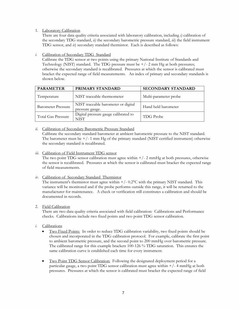
1. Laboratory CalibrationThere are four data quality criteria associated with laboratory calibration, including i) calibration of the secondary TDG standard, ii) the secondary barometric pressure standard, iii) the field instrument TDG sensor, and iv) secondary standard thermistor. Each is described as follows:
i. Calibration of Secondary TDG Standard Calibrate the TDG sensor at two points using the primary National Institute of Standards and Technology (NIST) standard. The TDG pressure must be +/- 2 mm Hg at both pressures; otherwise the secondary standard is recalibrated. Pressures at which the sensor is calibrated must bracket the expected range of field measurements. An index of primary and secondary standards is shown below.
PARAMETER PRIMARY STANDARD SECONDARY STANDARD
Temperature NIST traceable thermometer Multi-parameter probe
Barometer Pressure NIST traceable barometer or digital pressure gauge. Hand held barometer
Total Gas Pressure Digital pressure gauge calibrated to NIST TDG Probe
ii. Calibration of Secondary Barometric Pressure Standard
Calibrate the secondary standard barometer at ambient barometric pressure to the NIST standard. The barometer must be +/- 1 mm Hg of the primary standard (NIST certified instrument) otherwise the secondary standard is recalibrated.
iii. Calibration of Field Instrument TDG sensor
The two point TDG sensor calibration must agree within +/- 2 mmHg at both pressures, otherwise the sensor is recalibrated. Pressures at which the sensor is calibrated must bracket the expected range of field measurements.
iv. Calibration of Secondary Standard Thermistor
The instrument's thermistor must agree within +/- 0.2°C with the primary NIST standard. This variance will be monitored and if the probe performs outside this range, it will be returned to the manufacturer for maintenance. A check or verification still constitutes a calibration and should be documented in records.
2. Field Calibration
There are two data quality criteria associated with field calibration: Calibrations and Performance checks. Calibrations include two fixed points and two point TDG sensor calibration.
i. Calibrations
• Two Fixed Points: In order to reduce TDG calibration variability, two fixed points should be chosen and incorporated in the TDG calibration protocol. For example, calibrate the first point to ambient barometric pressure, and the second point to 200 mmHg over barometric pressure. The calibrated range for this example brackets 100-126 % TDG saturation. This ensures the same calibration curve is established each time for every instrument.
• Two Point TDG Sensor Calibration: Following the designated deployment period for a
particular gauge, a two point TDG sensor calibration must agree within +/- 4 mmHg at both pressures. Pressures at which the sensor is calibrated must bracket the expected range of field
7

measurements. If the pressure is not +/- 4 mmHg of the standard, the data will considered “suspect” and handled as described in “Reviewing Data Quality”.
ii. Performance checks (Portland and Seattle Districts)
There are four data quality criteria associated with performance checks: TDG pressure compared to secondary standard; standby probes deployed; thermistor compared to secondary standard; and field barometer compared to secondary standard. Each is described as follows:
• TDG Pressure Compared to Secondary Standard: After the deployment period, prior to removal
of the field instrument, the TDG pressure will be compared to the secondary standard. The actual decision point regarding adjusting the data would be in the lab following the two point TDG sensor calibration described in field instrument post calibration. The field comparison actually involves sampling precision and should not be used as a decision point for shifting data.
• Standby Probe Deployed: During initial deployment of a new TDG probe, after sufficient time
for equilibration (up to one hour), the TDG pressure must be +/- 10 mmHg of the secondary standard otherwise another (standby) probe is deployed.
• Thermistor Compared to Secondary Standard: During initial deployment of the new instrument,
the thermistor will be +/- 0.4°C of the secondary standard, corrected for calibration, or the instrument will be replaced with a standby.
• Field Barometer Compared to Secondary Standard: At each visit the field barometer reading
should the same as the secondary standard or the field barometer will be calibrated. iii. Performance checks (Walla Walla District)
There are three data quality criteria associated with performance checks: TDG pressure and water temperature compared to a replacement sonde (which is considered a secondary standard) and field barometer compared to a secondary standard. Each is described as follows:
• TDG Pressure Compared to Replacement Sonde: After the deployment period, the TDG
pressure will be compared to that of the replacement sonde. Comparisons are made using one of two methods: 1) the replacement sonde will be deployed nearby the in-place field sonde if possible or 2) the field sonde will be removed from the deployment tube and both it and the replacement sonde will be tied together and deployed for comparison. After sufficient time for equilibration, the TDG pressures must be +/- 10 mmHg of each other, otherwise another replacement sonde is deployed for comparison. After the comparisons are made, the field sonde is removed and the replacement sonde is deployed.
• Thermistor Compared to Replacement Sonde: Thermistors will be +/- 0.4°C of each other,
corrected for calibration, otherwise another replacement sonde is deployed for comparison. The sensor must be deployed to a depth where the compensation depth is sufficient to accommodate the change in pressure relative to the atmosphere, otherwise the TDG measurements may be underestimated. If the site does not accommodate maintaining the probe at greater than the compensation depth for more than 95% of the measuring cycle, investigations will begin to re-locate the fixed monitoring station. 3. Repair of Malfunctioning Gauges: The Corps, or their contractors, will have an adequate inventory of spare instruments that will be maintained to ensure that at least one backup monitor will be made available for deployment as
8

necessary. A malfunctioning instrument will generally be repaired within 24 to 48 hours from the time that the malfunction has been detected, depending on the remoteness of the instrument location and TDG conditions. A gauge malfunction that occurs during the weekend may require a longer response time depending upon when the detection of the malfunction has occurred and availability of capable technician/equipment). High priority will be placed on fixing a faulty instrument when TDG are or expected to be in excess of the current state standards. Corps staff and/or contractors will maintain TDG instruments. Instruments needing repairs that are beyond the staff's capability will be shipped to the manufacturer. In-house water quality and information management will do repairs of communication network systems. USGS Stennis Center (MS) staff will handle Service and repairs of the Sutron DCPs. Service and repairs of the Zeno DCPs will be performed by a contractor. To help reduce response time in determining whether an emergency field visit is needed, the following decision-making procedure was developed by the WQT:
• No emergency trips are made for the parameter of temperature.
• For gas and barometric pressure, if more than 25% of the hourly values are missing, then an
emergency trip is needed.
• If the difference in values between two consecutive stations is larger than 20 mm Hg for gas pressure, or 14 mm Hg for barometric pressure, then an emergency trip is triggered. This criterion does not apply if:
a. there is a transient “spike” for a parameter. b. if the higher-than-expected gas pressure value is associated with spill operations.
• If gas parameters at a station do not fall within any of the Corps Engineering Research and Development Laboratory (ERDC) generated/RCC generated gas production curves, are not caused from operational or structural changes, and these data persist for over 48 hours, then an emergency visit is triggered.
If there is uncertainty with an abnormal reading at a fixed monitoring station that is expected to persist for more than 48 hours, the COE will notify a WQT chairperson as soon as possible via email. The WQT should develop a recommendation to TMT, and to IT if necessary. If the COE plans to change fish passage actions because of the uncertainty, it should notify both the TMT & WQT members of the proposed change. TMT members will determine whether or not a meeting or conference call is needed and advise the COE of this need. The COE will then convene a TMT meeting, if requested to do so. If an abnormal reading at the gas monitoring station persists for more than 48 hours, the Corps will adopt the 2000 Plan of Action language on the subject. According to the May 2, 2000 letter from the Corps to NMFS, "If the WQT chairs determine a water quality issue exists, the issue will be framed by the WQT and forwarded from the chairs of the WQT to the chair of TMT or IT, as appropriate. Each state's fishery and water quality agencies and tribes will work together prior to any TMT meeting on this issue to balance and assure consistency of the proposed actions with fishery management requirements and state water quality standards." B. Reviewing Data QualityThe data from the fixed monitoring stations will be sent to the USACE-NWD’s CROHMS database which stores the raw data. At the same time, data from the FMS operated by the Portland and Walla Walla Districts is sent to the USGS’s ADAP database. The USGS performs the review, correction and deletion process described below on ADAP’s data, thus storing corrected data.
9

1. Reviewing DataOnce data are received, one or more of the following review processes occur:
• Visually look at the tables of data: There are certain signs in the data that may indicate mechanical problems. An instance, when the TDG pressure rises to 1,000 mmHg suddenly, and remains at that level, there may be a membrane tear. If there are extreme changes in any parameter, this shows that the data is erroneous.
• A data checklist is completed. The data quality checklist shown below provides an example of
questions that can be used to assist in identifying problems with data.
• Review graphs of the data. Creating graphs of the data can show unusual spikes in a parameter and draw attention to potentially erroneous data quickly. Spikes in graphed data can suggest further investigation may be necessary. For instance, a sudden rise of 5o C in one hour stands out and is suspect. Figure 2 is an example of what is currently used.
2. Dealing with Suspect Data Once suspect data are identified, one of the following actions can be taken:
• Correct the data: If there is a constant amount of shift or a continual drift, the data can be corrected using the USGS NWIS software. This is not usually the case. Sensor drift can be handled using a linearly prorated correction.
• Delete the data: If there appears to be no means of correcting the data, then it is deleted from
the USGS ADAPS database and they inform the Corps of the erroneous data. The Corps can then decide what to do with the erroneous data.
If data recorded by the fixed sensors are different from those recorded during the calibration procedure, appropriate correction will be made to the current as well as past data already stored in CROHMS as soon as possible. Data corrections will be provided to the USACE-NWD on an on-going basis so that they can be incorporated into the database. C. Completeness of Data: Completeness of data includes method of calculation and the data quality criteria goal. 1. Completeness Calculation The calculation of data set completeness is based on temperature and %TDG, which encompasses barometric pressure and TDG pressure. Data completeness is not based on the completeness of one parameter but of an entire suite. 2. Completeness Goal Data collected at each site will be 95% of the data that could have been collected during the defined monitoring period. Only “verified” data will be considered to be part of the 95% and any suspect data will have been deleted. 4.4 Phase 4: Instrument Removal and Storage The seasonal water quality monitors will be removed shortly after the end of the monitoring season (31 August) by Corps staff or the USGS, except for those that are slated for continued fall-winter monitoring. Those removed will be serviced by the maintenance and service contractors and stored at a
10

convenient location until the beginning of the next monitoring season. A selected number of monitors and spare DCPs will be available for off-season special monitoring activities upon request. Seattle District owns its Sutron and Geomation DCPs, and maintains and stores them as needed. 4.5 Phase 5: Fall-Winter Monitoring. Fall-Winter monitoring of TDG will be consistent with what was recommended in the TDG TMDL’s for the Lower Columbia and the Lower Snake rivers. A TDG monitor will be installed in the tailraces of each project. 4.6 Phase 6: Data Compilation, Analysis and Storage Time and resource permitting, Corps staff and contractors will fill data gaps, perform statistical analyses, and develop trends and relationships between spill and TDG saturation. Efforts will be made to use the SYSTDG model, and finding ways to facilitate and/or improve user access to the TDG and TDG-related database. The SYSTDG model (developed by ERDC) will be available for in-season gas production predictions and screening. Data collected at and transmitted from all network stations will be ultimately stored at CENWD-CM-WR-N, where they can be accessed through a data management system such as HEC-DSS or download the information from the TMT website. 4.7 Phase 7: Program Evaluation and Summary Report An annual report will be prepared after the end of the normal (spring and summer) monitoring season to summarize the yearly highlights of the TDG monitoring program. Preparation for the annual report will begin with a post-season review, with participation by the Northwest Division Office, the three Corps Districts, the Bureau of Reclamation, the Mid-Columbia PUD’s, and the Regional Forum WQT. The report will include a general program evaluation of the adequacy and timeliness of the information received from the field, and how that information is used to help control TDG supersaturation and high water temperature in the Columbia River basin. Information on the performance of the instruments (including accuracy, precision and bias associated with each parameter) and the nature and extent of instrument failures will be documented. This summary should include statistics on data confidence limits. Division staff will prepare the Annual TDG Monitoring Report based on field input, other material provided by each District, and recommendations by the WQT. This report will also contain suggestions and recommendations to improve the quality of the data during the FY2006 monitoring program. 4.8 Phase 8: Special Field Studies As provided for in Phase 3, additional monitoring of dissolved gas saturation will be conducted on an as-needed basis. 5.0 COOPERATION WITH PARTICIPATING AGENCIES The Bureau of Reclamation, Douglas County PUD, Chelan County PUD, and Grant County PUDs currently monitor for total dissolved gases at their mainstem projects and have maintained a cooperative effort with the Corps in collecting and reporting total dissolved gas and related water quality parameters. It is expected that this cooperation will extend through the 2008 spill season. Idaho Power Company is believed to have been collecting some TDG information in the Hells Canyon Complex for use in numerical modeling for FERC re-licensing efforts. However, this information has not been as widely disseminated as the data from the rest of the TDG monitoring network. The following is a summary of the action plans for the cooperating agencies.
11

12
Bureau of Reclamation. Bureau of Reclamation TDG monitoring will continue at International Boundary and the Grand Coulee forebay and tailrace, and the Hungry Horse sites in 2008. Hourly data transmission to CROHMS will continue via the GOES satellite. Douglas County PUD. TDG monitoring will continue at the forebay and tailrace of Wells Dam in 2008. Hourly data from both of these stations will continue to be sent to the Corps. Chelan County PUD. Chelan County PUD will continue to monitor TDG in the forebays and tailraces of Rocky Reach and Rock Island dams in 2008. Hourly data from these four stations will continue to be posted in the Corps of Engineers’ CROHMS database. Public Utility District No. 2 of Grant County (Grant PUD). Grant PUD currently operates and maintains four fixed-site water quality monitoring stations that monitor depth (m), barometric pressure (mmHg), total dissolved gas (TDG; percent saturation), temperature (oC), dissolved oxygen (DO; mg/L), pH (units), and turbidity (NTU). Depth, barometric pressure, TDG, and temperature are monitored on an hourly basis throughout the year, while DO, pH, and turbidity are monitored on a bi-weekly basis throughout the year. Fixed site monitors are located midway across the river channel in the forebay and tailrace of each dam. Each fixed site water quality monitoring station is equipped with a Hydrolab Corporation Model DS4A®, DS4® or Minisonde® multi-probe enclosed in a submerged conduit. Multi-probes are connected to an automated system that allows Grand PUD to monitor depth, barometric pressure, temperature, and TDG on an hourly basis (year-round). A barometer is located at each fixed site and provides the atmospheric pressure readings necessary to correct the partial pressure readings taken by the Hydrolab multi-probes. Data is collected and recorded onto a Sutron 8210 DCP at the top of the hour. A PCBase2 operating system transmits hourly water quality data via radio/antenna links to a PC at each dam. Data is transferred from the PC to an Access database from which daily reports can be generated and distributed. Grab-sample readings of pH, turbidity, and DO are taken during each bi-weekly calibration throughout the year. Multi-probe calibration and maintenance for fixed monitoring sites follow established guidelines by U.S. Geological Survey (personal communication with Dwight Tanner) and Hydrolab Corporation. Fixed site multi-probes are exchanged bi-weekly (year-round) with a previously calibrated (12-72 hours) probe. Calibration is conducted in a controlled laboratory environment using certified equipment and recommended standard solutions. A secondary probe (QA) is deployed at each site for quality assurance/quality control (QA/QC) during maintenance and calibration. The QA probe is used to monitor probe sensor deviation and suggest future deployment or recalibration maintenance, and to collect grab sample readings of pH, turbidity, and DO Grant PUD currently posts total dissolved gas, temperature, discharge (kcfs), spill (kcfs) and spill percentage (%) data to its web-site: (www.gcpud.org/stewardship/waterquality.htm) on a daily basis. The data is generally posted by 12:00 pm each day for the previous day (1-day lag during weekdays and a 3-day lag over weekends). The one-day lag-time is necessary to conduct a QA/QC on all water quality data. Specific details of Grand PUD’s fixed site water quality monitors, maintenance and calibration procedures, and quality assurance methods can be reviewed in Grant PUD’s Final License Application, License Technical Appendix E-3.F (Duvall and Dresser 2003)..

Table 1: 2008 Dissolved Gas Monitoring Network
CALIBRATION FREQUENCY
STATION NAME STATION
CODE OWNER d,e,fDATES OF
OPERATION
FALL-WINTER a
SPRING-SUMMER b
Albeni Falls Forebay ALFI USACE-NWS April 1 – September 15 N/A 2 Weeks Albeni Falls Tailwater ALQI USACE-NWS April 1 – September 15 N/A 2 Weeks
Anatone ANQW USACE-NWW April 1 – August 31 N/A 3 Weeks Bonneville Forebay BON USACE-NWP April 1 – August 31 N/A 3 Weeks
Boundary CIBW USBR Year Round Monthly 2 WeeksCamas-Washougal CWMW USACE-NWP April 1 – August 31 N/A 3 Weeks
Cascades Island CCIW USACE-NWP March 1 – August 31 N/A 3 Weeks Chief Joseph Forebay CHJ USACE-NWS April 1 – September 15 N/A 2 Weeks Chief Joseph Tailwater CHQW USACE-NWS April 1 – September 15 N/A 2 Weeks Dworshak Tailwater DWQI USACE-NWW Year Round Monthly 3 Weeks
Grand Coulee Forebay FDRW USBR Year Round Monthly 2 Weeks Grand Coulee Tailwater GCGW USBR Year Round Monthly 2 Weeks Hungry Horse Tailwater HGHM USBR April 1 – September 30 N/A 2 Weeks
Ice Harbor Forebay IHRA USACE-NWW April 1 – August 31 N/A 3 Weeks Ice Harbor Tailwater IDSW USACE-NWW Year Round Monthly 3 Weeks
John Day Forebay JDY USACE-NWP April 1 – August 31 N/A 3 Weeks John Day Tailwater JHAW USACE-NWP Year Round Monthly 3 Weeks
Lewiston LEWI USACE-NWW April 1 – August 31 N/A 3 Weeks Libby Tailwater LBQM USACE-NWS April 1 – September 15 N/A 2 Weeks
Little Goose Forebay LGSA USACE-NWW April 1 – August 31 N/A 3 Weeks Little Goose Tailwater LGSW USACE-NWW Year Round Monthly 3 Weeks Lower Granite Forebay LWG USACE-NWW April 1 – August 31 N/A 3 Weeks Lower Granite Tailwater LGNW USACE-NWW Year Round Monthly 3 Weeks
Lower Monumental Forebay LMNA USACE-NWW April 1 – August 31 N/A 3 Weeks
13

14
CALIBRATION FREQUENCY
STATION NAME STATION
CODE OWNER a,b,cDATES OF
OPERATION
FALL-WINTER d
SPRING-SUMMER e
Lower Monumental Tailwater LMNW USACE-NWW Year Round Monthly 3 Weeks
McNary Forebay MCNA USACE-NWW April 1 – August 31 N/A 3 Weeks McNary Tailwater MCPW USACE-NWW Year Round Monthly 3 Weeks
Pasco PAQW USACE-NWW April 1 – August 31 N/A 3 Weeks Peck PAQW USACE-NWW April 1 – August 31 N/A 3 Weeks
Priest Rapids Forebay PRD Grant County PUD Year Round 2 Weeks 2 Weeks Priest Rapids Tailwater PRXW Grant County PUD Year Round 2 Weeks 2 Weeks Rock Island Forebay RIS Chelan County PUD April 1 – August 31 N/A Monthly Rock Island Tailwater RIGW Chelan County PUD April 1 – August 31 N/A Monthly Rocky Reach Forebay RRH Chelan County PUD April 1 – August 31 N/A Monthly Rocky Reach Tailwater RRDW Chelan County PUD April 1 – August 31 N/A Monthly
The Dalles Forebay TDA USACE-NWP April 1 – August 31 N/A 3 Weeks The Dalles Tailwater TDDO USACE-NWP Year Round Monthly 3 Weeks Wanapum Forebay WAN Grant County PUD Year Round 2 Weeks 2 Weeks Wanapum Tailwater WANW Grant County PUD Year Round 2 Weeks 2 Weeks
Warrendale WRNO USACE-NWP September 1 – May 31 Monthly 3 Weeks f
Wells Forebay WEL Douglas County PUD April 1 – August 31 N/A Monthly Wells Tailwater WELW Douglas County PUD April 1 – August 31 N/A Monthly
a. USACE = U.S. Army Corps of Engineers (NWP = Portland District, NWS = Seattle District, NWW = Walla Walla District) b. USBR = U.S. Bureau of Reclamation c. Data for all TDG monitoring stations is available at; http://www.nwd-wc.usace.army.mil/tmt/ d. For the purposes of Corps of Engineers TDG monitoring, “Fall-Winter Season” is defined as September 1 through March 31.
For the purposes of Bureau of Reclamation TDG monitoring, “Fall-Winter Season” is defined as October 1 through March 31. e. For the purposes of Corps of Engineers TDG monitoring, “Spring-Summer Season” is defined as April 1 through August 31.
For the purposes of Bureau of Reclamation TDG monitoring, “Spring-Summer Season” is defined as April 1 through September 30. f. The Warrendale TDG monitor will be recalibrated every three weeks from March 1 through May 31.

Table 2. List of Contact Persons in 2008
Project Name Position Phone # E-Mail
Norbert Cannon Chemist (208) 334-1540 [email protected]
Bryan Horsburgh Water Quality Regional Coordinator
(208) 378-5035 [email protected] Internat’l Bndry., Hungry Horse, Grand Coulee
Jim Doty Hydromet Data Transmission (208) 378-5272 [email protected]
Kent Easthouse Oversight (206) 764-6926 [email protected] Chief Joseph, Albeni
Falls, Libby Ray Strode Trouble-
shooting (206) 764-3529 [email protected]
Wells (Douglas) Rick Klinge Coordinator (509) 884-7191 [email protected]
Waikele (Kelee) Hampton Coordinator (509) 663-8121
x 4627 [email protected] Rocky Reach and Rock Island (Chelan County PUD) Mike
Blalock Data Manager (509) 669-1732
Ross Hendrick Limnologist (509) 754-5088 Ext. 2468 [email protected]
Priest Rapids and Wanapum (Grant County PUD) Tom Dresser
Manager of Fish, Wildlife, and Water Quality Program
(509) 754-5088 Ext. 2312 [email protected]
Steve Juul Coordinator (509) 527-7281 [email protected]
Russ Heaton Oversight (509) 527-7282 [email protected]
Dworshak, Low. Granite, Little Goose, Low. Monumental, Ice Harbor, McNary, Pasco, Anatone Greg Ruppert USGS/
Oversight (509) 527-2571 [email protected]
Jim Britton Coordinator (503) 808-4888 [email protected]
Joe Rinella USGS/ Contract Coordinator
(503) 251-3278 [email protected]
John Day, The Dalles, Bonneville, Warrendale, Skamania, Camas
Dwight Tanner USGS/ Oversight (503) 251-3289 [email protected]
Jim Adams Coordinator (503) 808-3938 [email protected]
Laura Hamilton Oversight (503) 808-3939 [email protected]
COE Northwest Division Program Coordination
Tina Lundell Data Manager (503) 808-3937 [email protected]
15

Figure 1: 2008 Dissolved Gas Monitoring
16

Figure 2: Graphs for Data Review
17