Embed Size (px)
Citation preview

Copyright
by
Michael Christopher Wehr
1995

TESTS ON THE INSTALLATION CHARACTERISTICS OF HIGH
STRENGTH FASTENERS IN LAP SPLICE JOINTS
by
MICHAEL CHRISTOPHER WEHR, B.S.C.E.
THESIS
Presented to the Faculty of the Graduate School
of The University of Texas at Austin
in Partial Fulfillment
of the Requirements
of the Degree of
Master of Science in Engineering
The University of Texas at Austin
May, 1995

TESTS ON THE INSTALLATION CHARACTERISTICS OF HIGH
STRENGTH FASTENERS IN LAP SPLICE JOINTS
APPROVED BY THE
SUPERVISING COMMITTEE:
________________________________ Michael D. Engelhardt
________________________________ Karl H. Frank

This thesis is dedicated to my partner for life
Deborah Dianne Kalisz Wehr
“one war, two children, three moves, and anything in the future...”

v
ACKNOWLEDGMENTS
I should begin by thanking my sponsor, the US Army, but that's a bit too
impersonal. The individual paratroopers who were willing to follow me and kept me
motivated get the first thanks. I would not be here if it were not for them.
Once here, there are many people who helped me make it to this day of writing a
note of thanks. Dr. Michael Engelhardt, my advisor convinced me that I had a chance to
make it through the curriculum even though I could not tell him the difference between
LRFD and ASD when he asked me what I had studied 10 years ago. You have my sincere
appreciation for instilling confidence. Dr. Frank was the first professor I met and the last
signature on this thesis. Thank you for your insights on my true interest in steel structures.
I am indebted to Darin Riggleman for his patience in assisting me in getting started
on the research for this thesis.
The staff of Ferguson laboratory provided everything a new research assistant
needed to survive. Wayne Fontenot, Wayne Little and Pat Ball helped me get oriented with
all the equipment I used. Ryan Green and Ray Madonna were critical due to my slow but
eventual understanding of electronic equipment. Blake Stasney kept me on track with just
the strange looks he would give me if I was trying something I shouldn't. I was always
impressed with the way everyone was willing to answer the numerous and redundant
questions of all students. A special thanks goes out to Laurie Golding, the expert in
logistics. Every officer in the Army would be lost without someone to keep the supplies on
line. Thanks again. Beth Miller, thank you for your dedication to helping any student in
need of assistance.
I would like to point out my gradatude towards Ranjit Gupta and Mike Gilroy.
Without them I would be here another semester still drilling bolts. Actually, their friendship
and patience is as valued as all their long hours of work.
As with any challenging experience, there are a few people I have been lucky
enough to share the struggle with. I am truly indebted to them for making my short time in
graduate school very rewarding. Jeff Schmitz has been invaluable as a friend and source of
motivation. Sarah, Valerie, and Reagan have been true inspirations for achievement. With
the help of Dr. Bollinger and Eric Soderberg I have avoided many possible set-backs. I

vi
want to thank Chad Corsten for his help and inspiration to stay up all those nights to finish
this thesis. Mike Smart was a great inspiration for working hard from the very beginning.
Thanks Vince for all the late night discussions on life and engineering in general. Best of
luck to you. Also, Kevin Moore enjoy the city by the bay, I'll be there someday. A special
thanks to Willie Ramirez and Robert Frosch for their friendship and photographic assistance.
Also, Rob Zorbel and Brad Wood, best of luck to you both. Joe Muscarella, thanks for your
friendship and mentorship, best of luck at West Point.
It is important for me to remember the people who are responsible from the
beginning for any success I enjoy. My parents and brothers and sisters are a constant source
of inspiration and love. Thank you.
As always, I have tried to thank everyone, yet without mention of my family. My
wife, Deborah and children, Rachel and baby Chuck, have helped me the most in getting me
through school, as with any challenge in my life. You have my heart.
Michael C. Wehr
December, 1994
ABSTRACT
vii
TESTS ON THE INSTALLATION CHARACTERISTICS OF HIGH
STRENGTH FASTENERS IN LAP SPLICE JOINTS
by
MICHAEL CHRISTOPHER WEHR, M.S.E.
The University of Texas at Austin, 1995
SUPERVISOR: Dr. Michael D. Engelhardt
The proper performance of slip-critical bolted joints requires adequate fastener
tensions. The Research Council on Structural Connections of the Engineering Foundation
requires minimum fastener tensions for these slip-critical connections. Past research done in
the field and laboratory indicates variations in final fastener tension. Different methods of
tightening fasteners and different conditions of the joined materials result in various final
fastener tensions.
This thesis describes the research of various methods of tightening fasteners by
conducting experiments on joints with instrumented fasteners. Electronic strain gauges
provide information that translates into real time fastener tension. The turn-of-nut and
calibrated wrench installation methods provide the main delineation between tests. Both of
these methods of installation rely upon a “snug tight” condition before application of a final
tightening pass. Tests conducted provide information on the adequacy of different “snug
tight” conditions. Also, variations in connected material thickness and out-of-flatness affects
final fastener tensions. Twenty-nine tests evaluate the results of using different
combinations of tightening and material conditions.
TABLE OF CONTENTS
ACKNOWLEDGMENTS .............................................................................................. v

viii
ABSTRACT ................................................................................................................... vii
LIST OF TABLES .......................................................................................................... ix
LIST OF FIGURES ........................................................................................................ xi
CHAPTER 1: INTRODUCTION ................................................................................... 1
1.1 GENERAL .................................................................................................... 1
1.2 CURRENT METHODS OF FASTENER INSTALLATION ........................... 2
1.3 SUMMARY OF PREVIOUS RESEARCH ...................................................... 3
1.4 OBJECTIVES OF RESEARCH ........................................................................ 5
1.5 OVERVIEW OF RESEARCH CONDUCTED ................................................ 5
1.6 ORGANIZATION OF REPORT ...................................................................... 6
CHAPTER 2: MEASURING OF PLATE DEFORMATION ........................................ 6
2.1 GENERAL .................................................................................................... 6
2.2 METHOD OF BENDING PLATES ................................................................. 10
2.3 DEFORMATION MEASUREMENTS BEFORE AND AFTER TESTS ....................................................................................... 12
2.4 DURING TEST MEASUREMENTS ............................................................... 12
2.5 GAP HISTORIES FOR TESTS ........................................................................ 14
CHAPTER 3: BEHAVIOR OF THE BTM STRAIN GAUGE ...................................... 15
3.1 GENERAL .................................................................................................... 15
3.2 CALIBRATION TESTS ON CONVENTIONAL A325 FASTENERS ........... 18
3.2.1 OVERVIEW OF TESTS PERFORMED ......................................... 18
3.2.2 RESULTS OF CALIBRATION TESTS .......................................... 21
3.3 STRAIN GAUGE IN BENDING, TORSION, AND YIELDING.................... 22
3.3.1 OVERVIEW OF TESTS PERFORMED ......................................... 26
3.3.2 RESULTS OF BENDING, TORSION, AND YIELDING TESTS .................................................................. 29
3.3.3 CONCLUSIONS FROM TESTS ..................................................... 40
CHAPTER 4: CONNECTION TESTS WITH CONVENTIONAL A325 FASTENERS .................................................................................................... 44
4.1 GENERAL .................................................................................................... 44
ix
4.2 3MM DEFORMED PLATES ........................................................................... 49
4.2.1 TURN-OF-NUT INSTALLATION METHOD ............................... 50
4.2.2 CALIBRATED WRENCH INSTALLATION METHOD .............. 59
4.2.3 TIGHTENING METHOD COMPARISON .................................... 66
4.3 6MM DEFORMED PLATES ........................................................................... 66
4.3.1 TURN-OF-NUT INSTALLATION METHOD ............................... 66
4.3.2 CALIBRATED WRENCH INSTALLATION METHOD .............. 70
4.3.3 TIGHTENING METHOD COMPARISON .................................... 74
4.4 PLATE DEFORMATION COMPARISON ..................................................... 76
CHAPTER 5: CONNECTION TESTS WITH HUCK C50L FASTENERS ................. 77
5.1 GENERAL .................................................................................................... 77
5.2 3MM DEFORMED PLATES ........................................................................... 81
5.2.1 SINGLE PASS INSTALLATION METHOD, WITH CONVENTIONAL BOLT SNUG ..................................................... 81
5.2.2 TIGHTENING METHOD COMPARISON .................................... 83
5.3 6MM DEFORMED PLATES ........................................................................... 85
5.3.1 SINGLE PASS INSTALLATION METHOD, NO SNUG ............. 85
5.3.2 PLATE DEFORMATION COMPARISON .................................... 86
CHAPTER 6: OVERALL SUMMARY AND CONCLUSIONS .................................. 87
APPENDIX A: GRIP HISTORIES FOR TESTS........................................................... 95
APPENDIX B: RESULTS OF CONNECTION TESTS WITH CONVENTIONAL A325 FASTENERS ................................................................ 132
APPENDIX C: RESULTS OF CONNECTION TESTS WITH HUCK C50L FASTENERS .................................................................................... 213
BIBLIOGRAPHY .......................................................................................................... 227
VITA ............................................................................................................................. 228
LIST OF TABLES
2.1 Plate thicknesses for three grip lengths ................................................................... 7
4.1 Summary of fastener loads for CD3TN12_.MTO series, snugging pass ................ 53

x
4.2 Summary of fastener loads for CD3TN12_.MTO series, tightening pass ............... 53
4.3 Summary of fastener loads for CD3TN12_.LTR series, snugging pass .................. 55
4.4 Summary of fastener loads for CD3TN12_.LTR series, tightening pass ................ 55
4.5 Summary of fastener loads for CD3TN12_.OTM series, snugging pass ................ 57
4.6 Summary of fastener loads for CD3TN12_.OTM series, tightening pass ............... 57
4.7 Summary of fastener loads for CD3CW25_.MTO series, snugging pass ............... 60
4.8 Summary of fastener loads for CD3CW25_.MTO series, tightening pass .............. 60
4.9 Summary of fastener loads for CD3CW25_.MTO series, touch-up pass ................ 60
4.10 Summary of fastener loads for CD3CW12_.LTR series, snugging pass ................. 62
4.11 Summary of fastener loads for CD3CW12_.LTR series, tightening pass ............... 62
4.12 Summary of fastener loads for CD3CW12_.LTR series, touch-up pass ................. 62
4.13 Summary of fastener loads for CD3CW12_.OTM series, snugging pass ............... 64
4.14 Summary of fastener loads for CD3CW12_.OTM series, tightening pass .............. 64
4.15 Summary of fastener loads for CD6TN12_.MTO series, snugging pass ................ 69
4.16 Summary of fastener loads for CD6TN12_.MTO series, 1st tightening pass ......... 69
4.17 Summary of fastener loads for CD6TN12_.MTO series, 2d tightening pass .......... 69
4.18 Summary of fastener loads for CD6TN254.MTO series, 25k snugging pass ......... 71
4.19 Summary of fastener loads for CD6TN254.MTO series, visual snug pass ............. 71
4.20 Summary of fastener loads for CD6TN254.MTO series, tightening pass ............... 71
4.21 Summary of fastener loads for CD6CW12_.MTO series, snugging pass ............... 72
4.22 Summary of fastener loads for CD6CW12_.MTO series, tightening pass .............. 72
4.23 Summary of fastener loads for CD6CW12_.MTO series, touch-up pass ................ 72
4.24 Summary of fastener loads for CD6CW25_.MTO series, snugging pass ............... 75
4.25 Summary of fastener loads for CD6CW25_.MTO series, tightening pass .............. 75
4.26 Summary of fastener loads for CD6CW25_.MTO series, touch-up pass ................ 75
5.1 Average Final Fastener Tension for Huck Fasteners, 3mm deformed plates .......... 84
5.2 Average Initial Fastener Tension for Huck Fasteners, 3mm deformed plates ......... 85
5.3 Summary of all 2” grip Huck Fastener Tests ........................................................... 87
6.1 Summary of fastener tensions - 2” grip, 3mm deformed plate tests ........................ 90

xi
6.2 Summary of fastener tensions - 3” grip, 3mm deformed plate tests ........................ 91
6.3 Summary of fastener tensions - 4” grip, 3mm deformed plate tests ........................ 92
6.4 Summary of fastener tensions - 2” grip, 6mm deformed plate tests ........................ 93
6.5 Summary of fastener tensions - 3” grip, 6mm deformed plate tests ........................ 93
6.6 Summary of fastener tensions - 4” grip, 6mm deformed plate tests ........................ 94
LIST OF FIGURES
2.1 All plates used for the three double shear lap splices .......................................... 8
2.2 Lap splice in test set-up ....................................................................................... 8
2.3 Dimensions of lap splice ...................................................................................... 9
2.4 Bars used for plate bending ................................................................................. 11
2.5 600 kip Satec test machine bending plate ............................................................ 11

xii
2.6 Flat reference bar on plate ................................................................................... 13
2.7 Calipers measuring the total thickness of flat bar, plate, and gap ........................ 13
2.8 During test gap measurements with feeler gauge ................................................ 15
3.1 Sheldon 10” horizontal lathe, 2mm drill bits also shown .................................... 17
3.2 M-Bond materials, acetone, syringe, BTM gauge, bolt, scale ............................. 17
3.3 Calibration of strain gauged fastener in the bolt tension jig ................................ 19
3.4 Bolt tension jig with fastener configuration ......................................................... 20
3.5 Variation of calibration factor, 4-1/4” conventional fasteners at different temperatures .................................................................................. 23
3.6 Variation of calibration factor in 3-1/4” conventional fasteners all warm ........... 24
3.7 Variation of calibration factor, 4-1/4” conventional fasteners all warm .............. 25
3.8 Variation of calibration factor in 5-1/4” conventional fasteners all warm ........... 25
3.9 Skidmore-Wilhelm bolt tension indicator ............................................................ 27
3.10 Initial snugging of fastener in Skidmore-Wilhelm with calibrated torque wrench .................................................................................................... 27
3.11 Hydraulic set-up for releasing pressure in Skidmore-Wilhelm during strain gauge test ................................................................................................. 28
3.12 BTM gauge and Skidmore load comparison lubricated nut and flat washer ............................................................................ 31
3.13 Torque wrench values for each tightening of fastener lubricated nut and flat washer ............................................................................ 31
3.14 Before / after diameters in plane A, lubricated nut, flat washer .......................... 32
3.15 Before / after diameters in plane B, lubricated nut, flat washer ........................... 32 3.16 Before / after diameters in plane C, lubricated nut, flat washer ........................... 32
3.17 Necking from TORQUED TENSION TEST WITH LUBRICATED NUT bending from TORQUED TENSION TEST WITH UNLUBRICATED NUT AND BEVELED WASHER .............................................................................. 33
3.18 Beveled washer and 8 flat washers in Skidmore-Wilhelm tension indicator ....... 35
3.19 BTM gauge and Skidmore load comparison lubricated nut and beveled washer ..................................................................... 36
3.20 Torque wrench values for each tightening of fastener lubricated nut and beveled washer ..................................................................... 36
3.21 Before / after diameters in plane A, lubricated nut, beveled washer ................... 37

xiii
3.22 Before / after diameters in plane B, lubricated nut, beveled washer .................... 37 3.23 Before / after diameters in plane C, lubricated nut, beveled washer .................... 37
3.24 BTM gauge and Skidmore load comparison unlubricated nut and flat washer ........................................................................ 38
3.25 Torque wrench values for each tightening of fastener unlubricated nut and flat washer ........................................................................ 38
3.26 Before / after diameters in plane A, unlubricated nut, flat washer ...................... 39 3.27 Before / after diameters in plane B, unlubricated nut, flat washer ....................... 39 3.28 Before / after diameters in plane C, unlubricated nut, flat washer ....................... 39
3.29 BTM gauge and Skidmore load comparison unlubricated nut and beveled washer ................................................................. 42
3.30 Torque wrench values for each tightening of fastener unlubricated nut and beveled washer ................................................................. 42
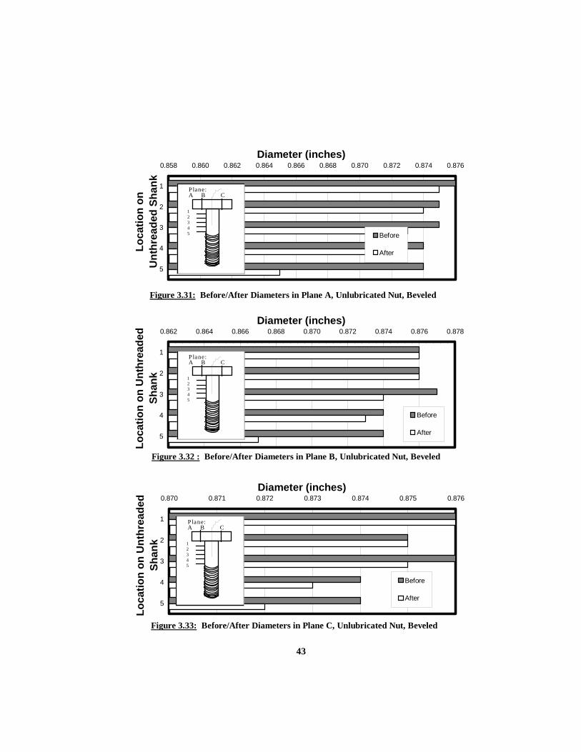
3.31 Before / after diameters in plane A, unlubricated nut, beveled washer ............... 43 3.32 Before / after diameters in plane B, unlubricated nut, beveled washer ................ 43 3.33 Before / after diameters in plane C, unlubricated nut, beveled washer ................ 43
4.1 Bolt lengths and grip lengths ............................................................................... 44
4.2 Rows of fasteners ................................................................................................. 45
4.3 Typical test set-up: bolted connection, support frame, and data acquisition system ............................................................................... 47
4.4 Support frame for bolted connection during test ................................................. 47
4.5 Bolt numbering template and tightening pattern sequence .................................. 48
4.6 4 foot pipe extension for turn-of-nut tightening .................................................. 51
4.7 600 ft lb calibrated torque wrench used for calibrated wrench tightening ........... 51
5.1 Fastener lengths and grip thickness ..................................................................... 77
5.2 Fastener numbering template and installation sequence ...................................... 79
5.3 Four conventional fasteners (41 kips of tension) before installation of Huck fasteners ............................................................................................... 83
Appendix A Index of Figures ......................................................................................... 96
Appendix B Index of Figures ......................................................................................... 133

xiv
Appendix C Index of Figures ......................................................................................... 214
1
1. CHAPTER 1 INTRODUCTION
1.1 GENERAL This thesis describes the methods and results of various tests performed to measure
fastener tension in a structural steel lap splice with deformed plates. Fastener tension is
critical to the performance of a steel slip-critical connection. Slip-critical connections
transmit applied loads using the frictional forces between connected surfaces. Fastener
tension induces the frictional forces within the connection.
This research reflects an effort to evaluate fastener installation provisions in the
“Specification for Structural Joints Using ASTM A325 or A490 Bolts”[1], by the Research
Council on Structural Connections. This publication is referred to as the Bolt Specification.
The standards for joint assembly and tightening of slip-critical connections were
investigated. Twenty-five of the twenty-nine connection tests conducted in this study used
either turn-of-nut tightening or calibrated wrench tightening on conventional 7/8 inch A325
galvanized fasteners. The last four tests, using the lock-pin and collar fastener, evaluated the
installation method of alternative design bolts. The lock-pin and collar fasteners used in this
study were manufactured by Huck International Inc, and will be referred to as Huck
fasteners in this study.
Four primary factors that affect fastener tension are the method of installation, the
sequence of tightening, the thickness and out-of-flat condition of the connected material, and
the degree of “snug tight” existing between the material before final tightening. The Bolt
Specification provides for four methods of fastener installation. The turn-of-nut and
calibrated wrench methods of installation provided a basis for fastener tension comparison
throughout this research. Each method of installation incorporated three different sequences
of tightening. One sequence followed the path of tightening fasteners from the middle of the
connection to the outside edges, as recommended in the Bolt Specification. Another
sequence involved tightening fasteners from one side of the connection to the other side.
Finally, the third sequence tightened fasteners on the outside of the connection followed by
tightening the middle fasteners. All tests used one of three connection thicknesses. All

2
connection tests used deformed plates. Specifically, the contour of the interior plate in the
lap splice was bent in single curvature to create a 3mm or 6mm gap. The two exterior plates
were flat. Three different snug tight conditions attempted to bring the deformed plates into
firm contact prior to final fastener tightening.
The study reported herein is continuation and extension of a similar study by
Riggleman (1994). The reader is referred to Riggleman’s thesis for further background on
this study.
1.2 CURRENT METHODS OF FASTENER INSTALLATION The Bolt Specification describes four methods of fastener installation for the
assembly of slip-critical connections. All methods must achieve at least the tension
identified as 70% of the minimum tensile strength of the fastener. For A325 bolts with a
diameter of 7/8”, the required minimum tension is 39 kips. Tightening may be done by
turning the bolt or the nut, provided one is held against rotation. The two methods of
installation evaluated in this research are the turn-of-nut and calibrated wrench methods.
The turn-of-nut method relies on a specified rotation of the nut to achieve a
minimum of 39 kips of tension. This turn-of-nut occurs after the plies of the material in the
connection are in firm contact. The Bolt Specification requires that a sample of three
fastener assemblies are tested in a device capable of measuring bolt tension. The tested
samples must achieve a tension not less than 41 kips, (5% greater than the minimum of 39
kips). The method of estimating the snug tight condition (when the plies are in firm contact)
must be verified. When snugging the plies together and when applying the turn-of-nut, the
sequence of fastener tightening should progress from the most rigid part of the connection to
the free edges. More than one snugging pass may be required to achieve the snug tight
condition. After achieving the snug tight condition, the amount of nut rotation depends on
the bolt length. For the length of fasteners used in this research, the rotation was either 1/3
or 1/2 of a turn.
The calibrated wrench method must achieve the same 41 kips of tension when
evaluated with three sample fasteners in a tension measuring device. The method must not
produce a rotation of the nut beyond what is required of the turn-of-nut method. A hardened
washer is required under the element being turned. The wrench must be calibrated at least

3
daily and if there is a change in the condition of the equipment or fasteners. The actual
tightening pass with a calibrated wrench occurs after the plies of the connection are in the
snug tight condition. The sequence follows the same path of moving from the most rigid
portion of the connection to the free edges. More than a single pass of tightening may be
required.
1.3 SUMMARY OF PREVIOUS RESEARCH The four primary factors affecting final fastener tensions have been addressed to
some degree in various publications. The literature search revealed two studies that focused
on field conditions and one study based mainly in the laboratory. The Bolt Specification [1]
and another design criteria publication make up the total of five publications with
information pertinent to this report.
The turn-of-nut and calibrated wrench methods of installation are directly compared
in the tests conducted in this report. Section 1.2 addressed the specifics of the two methods
as indicated in the Bolt Specification. Kulak, Fisher, and Struik [2] mention that the turn-of-
nut method achieves higher fastener tensions. This appears to be true if the process of
installation follows the Bolt Specification guidance of achieving firm contact between plates
before the final turn-of-nut. However, both field studies reviewed in the literature search
reveal the challenges of implementing the turn-of-nut method of installation. Kulak and
Obaia [3] documented the findings observed during the construction of three bridges. 7/8”
diameter A325 fasteners were installed using the turn-of-nut method. The bolting crews did
not follow the requirements of the Bolt Specification completely. Using an impact wrench,
fasteners were often completely tightened without a snugging pass to bring connected
materials together. Also, the actual rotation of the nut was not monitored closely. Based on
the sound of the impact wrench, a fastener was determined to be tight. However, despite
this, almost all fasteners were at the required minimum tensions upon inspection. The
critical observation at the end of this particular publication is that this result would not have
been obtained had the connected materials been deformed.
Notch [4] further exposes the problems with the turn-of-nut method encountered in
the field. Testing and observations focused on the installation of 1” diameter A490 fasteners
in oversized holes. In the process of investigating the effects of not having the proper

4
hardened washers, many fasteners were found to have below minimum tensions.
Observations indicated similar discontinuities in keeping track of the rotation of the nut.
Also, bolt crews often did not apply a snugging pass before the complete tightening of a
fastener.
Notch [4] makes an important point when comparing the turn-of-nut method and
the calibrated wrench method. While there were problems in the past with the calibrated
wrench method achieving dependable results, the turn-of-nut method has a potentially more
serious short fall. The turn-of-nut method is not effective unless a snug tight condition is
achieved first. This is demonstrated in some of the tests of this report. As will be discussed,
defining this snug tight condition may be more difficult than ensuring accurate calibrated
wrench tensions. Notch proposes a more stringent calibrated wrench method.
Foreman and Rumpf [5] did a series of tests with A325 bolts to validate the
capacities of bolted connections. The focus of their research was to prove the overly
conservative nature of replacing rivets with bolts, one for one. Almost as a side note,
mention was made of the need to touch-up fasteners with an additional turn-of-nut after the
first turn-of-nut pass. The method of determination involved the operator of the impact
wrench checking the tightness by the sound of the impact wrench. Very few fasteners
required additional rotation of the nut. However, the requirement of applying only one turn-
of-nut pass, as indicated in the Bolt Specification, precludes an operator from doing this
check. This offers some credence to the suggestion of Notch for a more stringent calibrated
wrench method.
The Bolt Specification requires that the snugging and tightening sequence must
progress from the most rigid part of the connection to the free edges. The field studies of
Kulak and Obaia [3] and Notch [4] indicate that this does not necessarily happen. Both
studies focus on other factors that were considered more critical in achieving the minimum
tensions. Therefore, one aspect of this current research is to investigate the differences
between tightening sequences.
Observations by Birkemoe [6] on the effects of out-of-flat plates within the
connection are of significant interest in regard to the research conducted for this report. The
publication produces evidence of low fastener tensions due to out-of-flat plates. The
connections tested are similar to those used throughout this report. Connections of the

5
publication consisted of single or triple curvature interior plates between two exterior flat
plates. The intent was to simulate the plate distortion that might occur due to welding,
handling, or erection. During the snugging pass and the tightening pass, fasteners were
found to loose significant amounts of tension. Normally, the fasteners first tightened lost the
most tension. Birkemoe also comments on the need for multiple snug passes to achieve the
snug tight condition called for in the Bolt Specification.
Notch [4] identifies the reliance the turn-of-nut method places on the snug tight
condition. The rotation of the nut required to achieve the minimum tensions is not clearly
apparent if the turn-of-nut is doing the job of a snugging pass. The Bolt Specification
indicates the need for the snug tight condition, however, Notch points out that the definition
of snug tight is “elusive”.
1.4 OBJECTIVES OF RESEARCH The proper performance of slip-critical bolted connections requires adequate
fastener tensions. Different methods of tightening fasteners within a connection result in
various final fastener tensions. The primary objective of this report is to evaluate the final
fastener tensions for each method of tightening. The two secondary objectives are to
validate the method of measuring fastener tensions and to describe the various degrees of
snug tight for each connection test. With the descriptions of snug tight and the results of the
tests, some correlation can be made to define the abstract definition of the snug tight
condition in the Bolt Specification. This research evaluates the effects of the installation
method, the tightening sequence, the connection thickness / deformation, and the snug tight
condition.
1.5 OVERVIEW OF RESEARCH CONDUCTED Three phases of research constitute the formulation of this report. They are outlined
below:
Phase I: Review of literature.
Phase II: Behavior of the strain gauge in measuring fastener tension.
Phase III: Examination of fastener tensions in connection tests.

6
The literature review of Phase I was detailed in Section 1.3 of this chapter. Phase II
consisted of a series of tests to verify the value of tension indicated by the strain gauge inside
a fastener. Specifically, the effects of bending, torsion, and fastener yielding were
investigated. Phase III constituted the majority of the research. Twenty-nine connection
tests provided detailed information on the various combinations of the installation method,
sequence of tightening, plate thickness / deformation, and the degree of the snug tight
condition.
1.6 ORGANIZATION OF REPORT Four chapters are dedicated to documenting Phases II and III mentioned in Section
1.5. Chapter 2 describes the type of connection used for all tests. A description of
measuring plate out-of-flatness and the snug tight condition for all tests is the primary
purpose of Chapter 2. Chapter 3 documents the behavior to the strain gauge used to measure
bolt tension. The effects of torsion, bending, and yielding are all investigated in Chapter 3.
Chapter 4 and Chapter 5 summarize the fastener tensions for conventional fastener tests and
lock-pin and collar fastener tests, respectively. For each test, these two chapters describe the
specific combination of the four primary factors that affect fastener tension. These factors
are the installation method, the tightening sequence, the plate thickness / deformation, and
the snug tight condition. Chapter 6 presents the summary and conclusions of this research.
2. CHAPTER 2 MEASURING OF PLATE DEFORMATION
2.1 GENERAL A connection test consisted of 12 fasteners installed in a three plate lap splice. The
splice was made up of a thick interior plate with thinner plates on the exterior. Specifically,
the middle plate was twice the thickness of an exterior plate. All tests involved the same
7
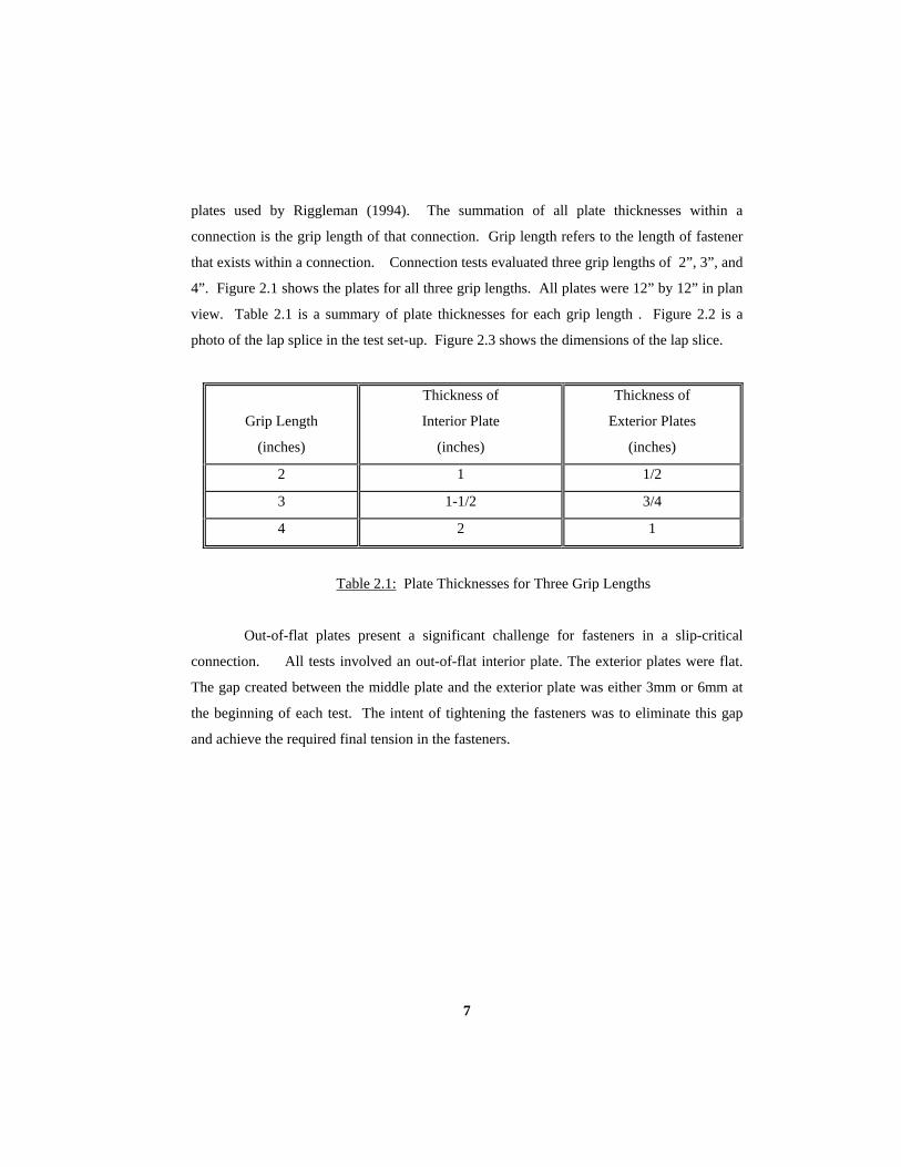
plates used by Riggleman (1994). The summation of all plate thicknesses within a
connection is the grip length of that connection. Grip length refers to the length of fastener
that exists within a connection. Connection tests evaluated three grip lengths of 2”, 3”, and
4”. Figure 2.1 shows the plates for all three grip lengths. All plates were 12” by 12” in plan
view. Table 2.1 is a summary of plate thicknesses for each grip length . Figure 2.2 is a
photo of the lap splice in the test set-up. Figure 2.3 shows the dimensions of the lap slice.
Grip Length
(inches)
Thickness of
Interior Plate
(inches)
Thickness of
Exterior Plates
(inches)
2 1 1/2
3 1-1/2 3/4
4 2 1
Table 2.1: Plate Thicknesses for Three Grip Lengths
Out-of-flat plates present a significant challenge for fasteners in a slip-critical
connection. All tests involved an out-of-flat interior plate. The exterior plates were flat.
The gap created between the middle plate and the exterior plate was either 3mm or 6mm at
the beginning of each test. The intent of tightening the fasteners was to eliminate this gap
and achieve the required final tension in the fasteners.

8
Figure 2.1: All plates used for the three double shear lap splices
Figure 2.2: Lap splice in test set-up

9
Section AA (front)
Figure 2.3: Dimensions of lap splice
1.5”
1.5”four rows at 3”
3”
3”
3”
3”
12”
AA
B
B
(plan)
3mm or 6mm gap
Section BB (right side)
t/2
t/2
t
longitudinal axis

10
It should be noted that the three grip lengths correspond to the three bent plate
thicknesses. Two grip lengths of equal total thickness, but with different thickness middle
plates will not produce the same test results. The intent of the three grip lengths is to
demonstrate the outcome of using three different thicknesses of bent plates. More force is
necessary to close the gap of a thicker bent interior plate.
This chapter describes the condition of the plates throughout the testing as well as
the preparation (Section 2.2) and measurement (Section 2.3) of each plate. Before every test,
each plate was measured and “shaped” as necessary through plastic bending. Exterior plates
were flattened to within 0.01”. Middle plates were bent to the required gap of 3mm (0.118”)
or 6mm (0.236”). All tests involved two methods of measuring the gap created by the shape
of the plates. The information from these two measuring methods is presented for each test
in Section 2.5. Plots in Appendix A graphically shows the change in gap around the
perimeter of the connection, after the snugging and tightening passes.
2.2 METHOD OF BENDING PLATES In preparation for every test, exterior plates had to be made flat and interior plates
had to be bent to the required gap. Cold bending changed the shape of the plates. To bend a
plate, two bars supported the edges of the plate while a load was applied along the span
between the supports. A 600 kip test machine applied the load necessary for bending as
pictured in Figure 2.4 and Figure 2.5. The supports and applied load were along the entire
length of the plate. The single curvature induced (or removed for flat plates) was opposite in
direction to the applied loading. This curvature is about the longitudinal axis of the lap
splice.
The initial gap measured between the middle plate and the top plate was 3mm for
21 tests and 6mm for 8 tests. Two of the four figures for each test in Appendix A
graphically show the shape of this curve for the front and back edges of the middle plate.
Depending on the locations of the holes, the front or back edge curves varied slightly from
each other. A flat bar resting on top of the plate provided a reference to measure the
curvature and flatness of the plate. Calipers measured the gap between the flat bar and the
plate. This process is described in Section 2.3.

11
Figure 2.4: Bars used for plate bending
Figure 2.5: 600 kip Satec test machine bending plate

12
2.3 DEFORMATION MEASUREMENTS BEFORE AND AFTER TESTS
The first method of gap measurement consisted of recording the bend that existed in
each plate before it was placed in the connection. This bend is described as the curve that
exists in a plate when looking at its front view. Relative to the alignment of the plate in the
connection, this curve is about the longitudinal axis of the splice connection. Eleven
locations at 1” intervals along the sides of each plate identify the gap measurement locations.
These eleven locations are seen in Figure 2.3, along the edges of the front and right side
views.
The front and back edges of each plate were measured for curvature. The left and
right edges remained fairly flat throughout all testing. Therefore, no initial measurements
were taken along these edges until the plates were in the connection test. Before each test, a
single flat bar (1/2”x15”x2”) provided a reference for all front and back edge deformation
measurements. As seen in Figure 2.6, the flat bar created a gap between itself and the curved
surface of a plate. Calipers measured the total thickness of the flat bar, the plate, and any
gap that existed between the two, as seen in Figure 2.7. Subtracting the known thicknesses
of the bar and the plate from each of these measurements produced the gap depth. Applying
a load as described in Section 2.4 shaped the plate to the necessary flatness or curvature.
The gap depth was measured both before and after each test. The gap depth measured before
the test provided the data for the “no load” gap for the figures of Appendix A. The gap
depth measurements described in the next section provided the data for the “snug” gap, the
“tight” gap and the “touch-up” gap for the figures of Appendix A.
2.4 DURING TEST MEASUREMENTS The measurement of the gap between plates during a connection test was a
challenge. Ideally, the gap that existed between plates throughout the connection could be
directly obtained. The particular gaps of interest would be the gap after a snug pass and the
gap after a tightening or touch-up pass. However, a method to “get inside the connection”
to measure the gap was beyond the scope of this research. The method actually used

13
Figure 2.6: Flat reference bar on plate
Figure 2.7: Calipers measuring the total thickness of flat bar, plate, and gap
obtained gap information around the perimeter of the connection with the use of a feeler
gauge.Figure 2.8 shows the method of using the feeler gauge. The previous method of using
a flat bar and calipers would not fit on the plates when they were in the connection support

14
frame. A feeler gauge measured the gaps that existed between the plates while in the
connection. The gaps were measured after the snug, tight, and touch-up pass. Two levels of
gap were measured, specifically, the gap between the middle and top plate and the gap
between the middle and bottom plate. Data was taken around the entire perimeter of the
connection. As mentioned previously, the edges of the plates were marked at 1” increments.
These markings provided the locations of gap measurement with the feeler gauge. Eleven
locations were measured on the front and back of the connection, while eight locations were
measured on the left and right sides of the connection. Figure 2.3 shows the locations of
measurement. The feeler gauge measured the depth of the gap to within 0.005" increments.
It should be noted that the gap was not measured with a feeler gauge before the
snug pass. Information from the flat bar measuring method provided this initial "no load"
gap data. The closing of the gap for each test is described in Section 2.5. Information from
both methods of gap measurement create the curves presented in Appendix A.
2.5 GAP HISTORIES FOR TESTS Using the gap information described above, four figures (Appendix A) for each test
present the change in gap between plates during a test. The test designations, such as
“CD2TN123.MTO” are defined in Chapter 4. While data was obtained for eight gaps in
each connection (four sides for both the interior / top plates and interior / bottom plates) only
the gaps of interest are presented. The front and back gaps between the interior and top plate
are presented first. Then the left and right side gaps between the interior and bottom plates
is presented. All data is plotted in reference to the location along the 1” increments of the
exterior plates. The eight points of measurement for the side gaps represent the overlap in
the lap slice of the interior and exterior plates. Each figure plots the gap at the edge of the
plates. Up to four lines exist on each plot. The orientation of the plots is just as the plates
would be viewed while in the connection support frame. The lines represent the edge of the
lower plate creating a gap with the upper plate. In other words, for the first two figures of
each test the plotted lines are the edge of the interior plate while the top x-axis represents the
edge of the top flat plate. For the second two figures, the plotted lines represent the bottom
plate with respect to the edge of the middle plate. The edge of the middle plate shown as the
top x-axis is physically above the bottom plate due to the initial curve of the middle plate.
15
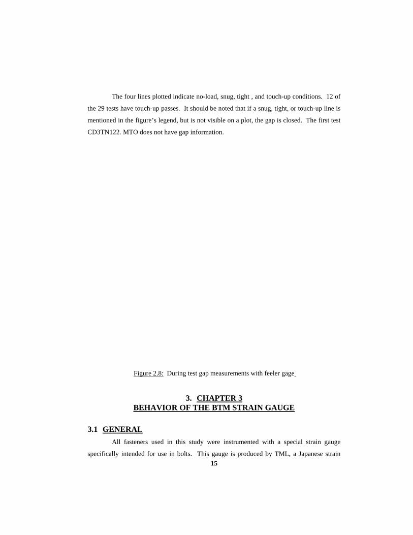
The four lines plotted indicate no-load, snug, tight , and touch-up conditions. 12 of
the 29 tests have touch-up passes. It should be noted that if a snug, tight, or touch-up line is
mentioned in the figure’s legend, but is not visible on a plot, the gap is closed. The first test
CD3TN122. MTO does not have gap information.
Figure 2.8: During test gap measurements with feeler gage
3. CHAPTER 3 BEHAVIOR OF THE BTM STRAIN GAUGE
3.1 GENERAL All fasteners used in this study were instrumented with a special strain gauge
specifically intended for use in bolts. This gauge is produced by TML, a Japanese strain

16
gauge manufacturer. This gauge is designated as type BTM-6C by TML, and will be
referred to simply as the BTM strain gauge in this report. The BTM gauge is installed in a
2mm diameter hole drilled through the head of the fastener, and is located along the
longitudinal axis of the fastener, in the upper unthreaded portion of the fastener. All tested
fasteners employed the method of gauge installation developed by Riggleman (1994). The
Sheldon 10" horizontal lathe used for drilling the 2mm diameter hole in the fasteners is
pictured in Figure 3.1. Also, all the materials and tools used for installing the gauge in the
2mm hole are pictured in Figure 3.2. These are the same materials specified by
Riggleman (1994).
Understanding the performance limits of the BTM strain gauge is essential to
research study. The calculation of bolt tension required an accurate method of converting
recorded strain (micro in/in) to a fastener tensile load measured in kips. Unique to each
fastener, a calibration factor converted strain to tensile load. Various tests with conventional
fasteners evaluated the accuracy of this calibration factor, as discussed in Section 3.2.
Fastener tension is the primary force sought after throughout all tests. The data
produced by the strain gauge in a fastener is the information required for calculating this
tension force. However, a fastener can experience torque, bending, and yielding depending
on the type of fastener, the condition of the plates, and the method of tightening. The effect
of these forces on the strain gauge data must be understood.
In an effort to simulate these three conditions, four tests evaluated the performance
of strain gauges in conventional fasteners. Torque occurs in conventional fasteners due to
the rotation of the nut. Any fastener can experience some amount of bending if the plates

17
Figure 3.1: Sheldon 10" horizontal lathe, 2mm drill bits also shown
Figure 3.2: M-Bond materials, acetone, syringe, BTM gauge, bolt, scale
are initially deformed. Conventional fasteners tightened with the turn-of-nut method usually
experienced the most yielding compared to calibrated wrench tightening and direct tension
Huck Fasteners. The set up and results of these four tests are discussed in Section 3.3.
Riggleman (1994) conducted a substantial number of tests to evaluate the accuracy
of the BTM strain gauge when used to measure tension in conventional and lock-pin and
collar fasteners. The additional calibration tests on conventional fasteners reported herein
are intended to supplement the work by Riggleman. The fasteners used in this current study
were taken from the same lots as those used by Riggleman.

18
3.2 CALIBRATION TESTS ON CONVENTIONAL A325 FASTENERS
3.2.1 OVERVIEW OF TESTS PERFORMED The calibration factor is the relationship between the fastener tension and strain
gauge output. For each fastener the load and strain data from a series of loadings established
a calibration factor. Specifically, a Satec Systems 600 kip tension / compression test
machine loaded a BTM strain gauged fastener in the fastener tension jig, as pictured in
Figure 3.3. The bolt tension jig with fastener configuration is also pictured in Figure 3.4.
The Satec machine was calibrated to a National Institute of Standards and Technology
certified load cell (NIST cell). The Satec loaded each conventional fastener to 40 kips using
10 kip increments. A digital data acquisition system consisting of a Hewlett Packard 3852
data acquisition unit (with digital voltmeter and multiplexer), constant voltage power supply,
and a 286 AT IBM compatible computer recorded the data. A total of nine readings
provided the data for the calibration factor. The nine readings for a conventional fasteners
were taken at the Satec dial readings of 0, 10, 20, 30, 40, 30, 20, 10, and finally 0 kips.
These nine readings are referred to as the cycle of calibration loading. A regression analysis
of the load and strain data produced a best fit slope of the load versus the strain. The
regression line was forced through the origin. This slope is the value used for the

19
Figure 3.3: Calibration of strain gauged fastener in the bolt tension jig

20
Figure 3.4: Bolt tension jig with fastener configuration

21
calibration factor, measured in kips. This calibration factor, when multiplied by the
recorded strains of the fastener, equates to tensile loads measured in kips. Figures 3.5a and
3.5b show sample plots used for this regression.
Initially, fasteners were cycled only once to obtain data for the calibration factor.
When a fastener was cycled for a second time, slight variation in this calibration factor was
observed. This indicated that the tension and strain relationship for other fasteners might be
different when loaded for a second time, as in a connection test. To evaluate this variance,
single fasteners were cycled numerous times. The 14 tests discussed in Section 3.2.2 show
some possible reasons for calibration factor variance, and indicate the steps taken to reduce
this variance.
3.2.2 RESULTS OF CALIBRATION TESTS The evaluation of calibration factor variance involved using 14 conventional
fasteners. As described in Section 3.2, a cycle of loading (0, 10, 20, 30, 40, 30, 20, 10, 0
kips) produced the data to calculate the calibration factor. Each fastener experienced
between 5-12 cycles of loading to investigate the changes in its calibration factor.
Initially, three 4-1/4” conventional fasteners were cycled eight times through the
calibration loading. Each displayed different trends in calibration factor variance.
Figure 3.5 shows the % change of the calibration factor between each cycle. Initially, the
temperature of the fastener was not considered a factor in the accuracy of the calibration
factor. However, a cold fastener demonstrated a jump in the calibration factor of
approximately 3% between the first cycle and the second cycle. The description of cold is
used to indicate a fastener at an air conditioned temperature of 70-75 degrees, Fahrenheit.
The description of “warm” is used to indicate a fastener at lab temperature, between 85-95
degrees, Fahrenheit.
There are two possible explanations for this influence of temperature on the
calibration factor. The cold fasteners exhibited more initial strain per load. There may be
some slip between the adhesive and the steel of the fastener. The other possibility is that
there is some minor initial elongation in the fastener. More tests are needed to verify these
possibilities.

22
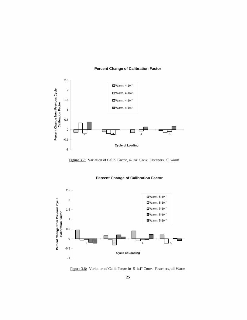
Based on this initial indication of calibration factor variance due to temperature, all
remaining fasteners were calibrated at lab temperature. All connections tests were conducted
at lab temperature. A series of 11 more fasteners were checked for calibration factor
stability. The results of these tests are plotted in Figures 3.6 through 3.8. There appeared to
be a general leveling off of the calibration factor after approximately 5 cycles. After making
this observation, the remaining fasteners in all subsequent connection tests used the
calibration factor from the fifth cycle of loading. In the presentation of connection test
results in Chapter 4, all tests used this fifth calibration factor, except the six tests in Sections
4.2.1.1 and 4.2.2.1.
Actual plots of the regression data for the warm and cold 4-1/4” fasteners is shown
in Figures 3.5a and 3.5b. These plots show the 1st and 5th calibration factors for these
fasteners. All four plots are fairly linear.
To maintain perspective in reference to the above discussion, the following two
points are made. For the six tests of Sections 4.2.1.1 and 4.2.2.1, only a few fasteners were
calibrated in the “cold” condition. Fasteners were usually moved from an air conditioned
room to the lab floor in groups of 12. After calibrating approximately 3 fasteners (30
minutes), the remainder should have been at approximately lab temperature. Therefore, only
about 25% of the fasteners in a connection test might have tension values that were low by
about 1 kip. Also, the second point is that the variance between the initial and fifth
calibration factor of a warm fastener resulted in about a 1/2 kip change in fastener tension
values. This 1/2 kip difference is noted at a load of 40 kips. Therefore, the six tests in
question might vary by about 1/2 kip, due to not using the fifth calibration factor.
3.3 STRAIN GAUGE IN BENDING, TORSION, AND YEILDING A total of four tests (one bolt each) investigated the effects of bending, torsion, and
yielding on the accuracy of the BTM strain gauge. For each test a strain gauged 4-1/4” long
7/8” A325 galvanized fastener was placed in a calibrated Skidmore-Wilhelm bolt tension
indicator as seen in Figure 3.9, (model # ML). This tension indicator was calibrated to the
Satec Systems 600 kip test machine, which was calibrated to the NIST cell mentioned
previously. A pressure transducer electronically measured the pressure in the Skidmore-.

23
Percent Change of Calibration Factor
-1
-0.5
0
0.5
1
1.5
2
2.5
2 3 4 5 6 7 8
Cycle of Loading
Perc
ent C
hang
e fr
om P
revi
ous
Cyc
le
Cal
ibra
tion
Fact
or
Warm, 4-1/4"
Unknown, 4-1/4"
Cold, 4-1/4"
Figure 3.5: Variation of Calib. Factor, 4-1/4" Conv. Fasteners at Different Temperatures
Figure 3.5a: 1st and 5th calibration factor (slope) for cold 4-1/4"
load v strain
0
10
20
30
40
0 1000 2000 3000microstrain =10E-6(in/in)
load
(kip
s)
Slope = 0.017365
load v strain
0
10
20
30
40
0 1000 2000 3000microstrain =10E-6(in/in)
load
(kip
s) Slope = 0.017845
1st Cycle 5th Cycle

24
Figure 3.5b: 1st and 5th calibration factor (slope) for warm 4-1/4"
load v strain
0
10
20
30
40
0 1000 2000 3000
load
(kip
s)load v strain
0
10
20
30
40
0 1000 2000 3000microstrain = 10E-6(in/in)
load
(kip
s)
Slope = 0.018196 Slope = 0.018221
microstrain = 10E-6(in/in)1st Cycle 5th Cycle
Percent Change of Calibration Factor
-1
-0.5
0
0.5
1
1.5
2
2.5
2 3 4 5 6 7 8 9 10 11 12
Cycle of Loading
Perc
ent C
hang
e fr
om P
revi
ous
Cyc
le
Cal
ibra
tion
Fact
or
Warm, 5-1/4"
Warm, 3-1/4"
Figure 3.6: Variation of Calib.Factor in 3-1/4" & 5-1/4" Conv. Fasteners, all Warm
25
Percent Change of Calibration Factor
-1
-0.5
0
0.5
1
1.5
2
2.5
2 3 4 5
Cycle of Loading
Perc
ent C
hang
e fr
om P
revi
ous
Cyc
le
Cal
ibra
tion
Fact
or
Warm, 4-1/4"
Warm, 4-1/4"
Warm, 4-1/4"
Warm, 4-1/4"
Figure 3.7: Variation of Calib. Factor, 4-1/4" Conv. Fasteners, all warm
Percent Change of Calibration Factor
-1
-0.5
0
0.5
1
1.5
2
2.5
2 3 4 5
Cycle of Loading
Perc
ent C
hang
e fr
om P
revi
ous
Cyc
le
Cal
ibra
tion
Fact
or
Warm, 5-1/4"
Warm, 5-1/4"
Warm, 5-1/4"
Warm, 5-1/4"
Warm, 5-1/4"
Figure 3.8: Variation of Calib.Factor in 5-1/4" Conv. Fasteners, all Warm

26
Wilhelm for both calibration and testing. This pressure was used to calculate the tension
indicated by the Skidmore-Wilhelm.
3.3.1 OVERVIEW OF TESTS PERFORMED The intent of each test was to simulate the loading that a fastener may experience
while being installed in a connection. The first aspect of loading was that most fasteners
were snugged to between 12 and 25 kips. The fastener would then lose some or most of this
preload as other fasteners in the connection were snugged. The next loading would be to
approximately 40 kips due to a tightening pass. Following that, with some more loss in
tension, there might be additional tightening due to a touch-up pass.
The sequence of loading for all six tests followed the same path. A calibrated
torque wrench initially snugged each fastener to 20 kips, as seen in Figure 3.10. Then the
tension in the fastener was brought to zero with a hydraulic pump releasing the pressure in
the Skidmore-Wilhelm. Figure 3.11 shows the hydraulic set-up. This release in tension was
to simulate the effect of other fasteners being snugged. The torque wrench then tightened
the fastener up to 40 kips. The tension in the fastener was then reduced to 20 kips to again
simulate the effects of tightening other fasteners. Following this, the torque wrench
simulated a touch-up pass with a series of one to three 1/4 turns of the nut. The 1/4 turn of
nut was used to get as much information as possible before possible fracture of the fastener.
At the point of apparent yielding, the load in the fastener was decreased to zero by
increments of 10 kips. In summary, all loading was done with a torque wrench, and all
unloading was done by lowering the pressure in the Skidmore with the hydraulic pump.
The value of torque was recorded for each specified load or nut rotation. Strain
gauge and pressure transducer readings were recorded at every change in tension. By
comparing the values of the strain gauge, the pressure transducer, and required torque, a
series of observations were made regarding the accuracy of the strain gauge readings. These
are discussed in Section 3.3.2.

27
Figure 3.9: Skidmore-Wilhelm bolt tension indicator
Figure 3.10: Initial snugging of fastener in Skidmore-Wilhelm with calibrated torque wrench

28
Figure 3.11: hydraulic pump set-up for releasing pressure in Skidmore-Wilhelm during strain gauge test

29
3.3.2 RESULTS OF BENDING, TORSION, AND YIELDING TESTS Each fastener was subjected to one of four distinct conditions to observe the effects
of torsion and bending. Using an ASTM A563 Grade DH nut (lubricated and galvanized) or
a non-galvanized and unlubricated nut constituted two conditions for torsion comparison.
The unlubricated nut was expected to induce higher torsion forces. The other two
conditions involved using a beveled washer in one test and only flat washers in the other test.
A beveled washer of 2.86 degrees simulated the maximum bending experienced by a
fastener in 3mm deformed plates. Five figures for each test illustrate the values of tension,
torque, and fastener yielding.
The initial figure for each test is a plot of BTM strain gauge loads and Skidmore-
Wilhelm loads measured with a pressure transducer. Both values are calibrated to the NIST
cell, and are measured in kips. They are plotted along the recorded load values indicated by
the dial of the Skidmore-Wilhelm. The dial served as a reference point for the initial target
loads of 0, 20, 0, 40, 20 kips and the unloading values of 40, 30, 20, and 0 kips. The three
1/4 turn-of-nut rotations occur after the hydraulic pressure release down to 20 kips. The
intent of the 1/4 turns is to simulate the loading of the fastener in a final tightening pass. The
value of 1/4 of a turn is used solely for the purpose of taking incremental readings of torque
and tension. The dial readings for each 1/4 rotation of the nut are on the longitudinal axis of
the plot between the initial target values and the unloading values.
The second figure for each test is a bar graph of torque required for each tightening.
For each test there are between five and six tightening passes done with the 600 ft lb torque
wrench. Each test required initial fastener tightening to the target loads of 20 and 40 kips.
The remaining fastener tightening was due to the subsequent 1/4 rotations of the nut. The
method of getting torque wrench values required gradual increases in the applied torque until
achieving the target loads or the 1/4 turn. Torque values above 600 ft lb required the use of
a 4X torque multiplier. The second figure of each test shows the torque required compared
to the same Skidmore-Wilhelm dial readings used in the first figure.
The final three figures for each test show the changes in the diameter of the
unthreaded shank of each fastener. This portion of the fastener is of particular interest
because the BTM strain gauge is located at the core of the unthreaded shank. It is indicated
on the diagram of each figure. The same type of calipers used to measure plate deformation

30
provided the information on diameter changes. Specifically, the diameter of the unthreaded
shank was measured at 15 locations. The six corners of the fastener head provided the
points for three imaginary planes cutting through the longitudinal side of the fastener. Five
levels (every 1/4” below the head of the bolt) along the longitudinal axis of the unthreaded
shank provided the location for measuring each of the diameters at the three planes. The
measurements of the diameter before and after the test provide the comparison illustrated in
the three figures. The comparison shows a reduction in diameter of the fastener. This
reduction of diameter is greatest near the threads. It is assumed that most of the yielding
occurs in the threads, however this shows some yielding in the unthreaded shank as well.
3.3.2.1 TORQUED TENSION TEST WITH LUBRICATED NUT As described in Section 3.3.1, a 4-1/4” conventional fastener was placed in the
Skidmore-Wilhelm for tension and strain gauge comparison. This test used a lubricated nut
with ten hardened flat washers. Figure 3.12 shows very close agreement between the tension
values of the BTM strain gauge and the pressure transducer in the Skidmore-Wilhelm. The
BTM gauge measured about 1-1.5 kips higher than the Skidmore value after the first 1/4
rotation of the nut. The Skidmore indicated a tension of 49 kips. After another 1/4 rotation
of the nut, apparent yielding in the threads caused a slight decrease in tension as indicated by
both the BTM gauge and the Skidmore. Upon complete unloading, no residual stress was
indicated in the BTM gauge. Figures 3.14 through 3.16 show that there was some
permanent necking of the unthreaded shank of the fastener, with no apparent effect on the
BTM gauge. Necking of the threaded portion of the fastener is visible in the Figure 3.17,
showing the tested fastener on the left. Also apparent is the amount of stretching that took
place compared to the other fastener in the picture.

31
0
10
20
30
40
50
60
0 20 0 40 20 48 50 47 46 40 30 20 10 0Skidmore-Wilhelm Dial (kips)
BTM
& P
ress
ure
Tran
sduc
er
Cal
ibra
ted
Load
(kip
s)
BTM Gauge
Skidmore-Wilhelm, PT
Figure 3.12: BTM Gauge and Skidmore Load Comparison, Lubricated Nut and Flat Washer
0100200300400500600700800900
1000
0 20 0 40 20 48 50 47 46 40 30 20 10 0
Skidmore-Wilhelm Dial (kips)
Torq
ue W
renc
h (ft
lb)
Figure 3.13: Torque for Each Tightening of Fastener, Lubricated Nut and Flat Washer
(releasing pressure)

32
0.865 0.866 0.867 0.868 0.869 0.870 0.871 0.872 0.873
1
2
3
4
5
Loca
tion
on U
nthr
eade
d Sh
ank
Diameter (inches)
Before
After
Figure 3.14: Before/After Diameters in Plane A, Lubricated Nut, Flat
0.864 0.865 0.866 0.867 0.868 0.869 0.870 0.871 0.872 0.873
1
2
3
4
5
Loca
tion
on U
nthr
eade
d Sh
ank
Diameter (inches)
Before
After
Figure 3.15: Before/After Diameters in Plane B, Lubricated Nut, Flat
0.864 0.865 0.866 0.867 0.868 0.869 0.870 0.871 0.872 0.873
1
2
3
4
5
Loca
tion
on U
nthr
eade
d Sh
ank
Diameter (inches)
Before
After
Figure 3.16: Before/After Diameters in Plane C, Lubricated Nut, Flat
A B C
12345
P lane:
A B C
12345
P lane:
A B C
12345
Plane:

33
Figure 3.17: Necking from TORQUED TENSION TEST WITH LUBRICATED NUT (left) Slight Bending from TORQUED TENSION TEST WITH UNLUBRICATED
NUT AND BEVELED WASHER (right)

34
3.3.2.2 TORQUED TENSION TEST WITH LUBRICATED NUT AND BENDING
This test used a lubricated nut, a beveled washer and 8 hardened flat washers.
Figure 3.18 shows a picture of the fastener and all washers in the Skidmore-Wilhelm
tension indicator. Figure 3.19 shows a consistent difference of about 1 kip between the
BTM strain gauge value and the value indicated by the Skidmore-Wilhelm. The BTM gauge
indicates the higher tension load. A residual strain corresponding to about 1 kip of fastener
tension also appeared in the BTM strain gauge upon complete unloading. In is not known as
to when this residual strain developed. Normally, residual strain is considered an indication
of yielding. However, this would indicate possible yielding at the initial 20 kip load. This
yielding may be due to the bending of the fastener. Figures 3.21 through 3.23 show that
there was some permanent necking of the unthreaded shank of the fastener. Also, the
fastener appeared to be permanently bent in the threaded portion of the fastener. This
bending is similar to the shape of fastener on the right side shown on Figure 3.17. The
actual fastener pictured is from the test described in Section 3.3.2.4.
3.3.2.3 TORQUED TENSION TEST WITH UNLUBRICATED NUT This test used an unlubricated nut with 9 hardened flat washers. Figure 3.24 shows
a variable difference of about 14-21 kips between the BTM strain gauge value and the
Skidmore-Wilhelm value for tension. This difference was apparent at the first 40 kip
loading of the fastener. The BTM gauge measured 62 kips of tension, indicating possible
yielding. A 16 kip value also appeared as residual strain in the BTM strain gauge upon
complete unloading. In is not known when this residual strain developed. The third curve
on Figure 3.24 is the original BTM gauge values with the residual load of 16 kips subtracted
from it. This “corrected” BTM gauge value does not match the Skidmore tension loads for
the dial values of 40, 20 and 45 kips. There is a 2-5 kip difference between the measured
loads. However, for the following two 1/4 turns and unloading increments, the values
agree very well.
At this point it is critical to note that this residual strain is subtracted from the strain
recorded in the fastener if an adjustment of over 1 kip results. This process was used

35
Figure 3.18: the beveled washer and 8 flat washers in Skidmore-Wilhelm tension indicator

36
05
101520253035404550
0 20 0 40 20 47 45 45 40 30 20 10 0Skidmore-Wilhelm Dial (kips)
BTM
& P
ress
ure
Tran
sduc
er
Cal
ibra
ted
Load
(kip
s)
BTM Gauge
Skidmore-Wilhelm, PT
Figure 3.19: BTM Gauge and Skidmore Load Comparison, Lubricated Nut and Beveled Washer
0100200300400500600700800900
0 20 0 40 20 47 45 45 40 30 20 10 0
Skidmore-Wilhelm Dial (kips)
Torq
ue W
renc
h (ft
lb)
Figure 3.20: Torque for Each Tightening of Fastener, Lubricated Nut and Beveled Washer
(releasing pressure)

37
0.870 0.871 0.872 0.873 0.874 0.875 0.876
1
2
3
4
5
Loca
tion
on
Unt
hrea
ded
Shan
kDiameter (inches)
Before
After
Figure 3.21: Before/After Diameters in Plane A, Lubricated Nut, Beveled
0.867 0.868 0.869 0.870 0.871 0.872 0.873 0.874 0.875 0.876
1
2
3
4
5
Loca
tion
on U
nthr
eade
d Sh
ank
Diameter (inches)
Before
After
Figure 3.22: Before/After Diameters in Plane B, Lubricated Nut, Beveled
0.870 0.871 0.872 0.873 0.874 0.875 0.876
1
2
3
4
5
Loca
tion
on U
nthr
eade
d Sh
ank
Diameter (inches)
Before
After
Figure 3.23: Before/After Diameters in Plane C, Lubricated Nut, Beveled
A B C
12345
P lane:
A B C
12345
P lane:
A B C
12345
P lane:

38
0
10
20
30
40
50
60
70
0 20 0 40 20 45 50 51 40 30 20 10 0Skidmore-Wilhelm Dial (kips)
BTM
& P
ress
ure
Tran
sduc
er
Cal
ibra
ted
Load
(kip
s)
BTM Gauge
Corrected BTM Gauge
Skidmore-Wilhelm, PT
Figure 3.24: BTM Gauge and Skidmore Load Comparison, Unlubricated Nut and Flat Washer
0
200
400
600
800
1000
1200
0 20 0 40 20 45 50 51 40 30 20 10 0
Skidmore-Wilhelm Dial (kips)
Torq
ue W
renc
h (ft
lb)
Figure 3.25: Torque for Each Tightening of Fastener, Unlubricated Nut and Flat Washer
Correction
(releasing pressure)

39
0.860 0.862 0.864 0.866 0.868 0.870 0.872 0.874 0.876
1
2
3
4
5
Loca
tion
on
Unt
hrea
ded
Shan
kDiameter (inches)
Before
After
Figure 3.26: Before/After Diameters in Plane A, Unlubricated Nut, Flat
0.860 0.862 0.864 0.866 0.868 0.870 0.872 0.874 0.876
1
2
3
4
5
Loca
tion
on U
nthr
eade
d Sh
ank
Diameter (inches)
Before
After
Figure 3.27: Before/After Diameters in Plane B, Unlubricated Nut, Flat
0.864 0.866 0.868 0.870 0.872 0.874 0.876 0.878 0.880 0.882
1
2
3
4
5
Loca
tion
on U
nthr
eade
d Sh
ank
Diameter (inches)
Before
After
Figure 3.28: Before/After Diameters in Plane C, Unlubricated Nut, Flat
A B C
12345
P lane:
A B C
12345
P lane:
A B C
12345
P lane:

40
for all tests. The residual strain is subtracted from all the strains of a fastener recorded after
the last tightening of the fastener. Any attempt to adjust values before the last tightening is
subject to error because the actual point of residual strain development is unknown. Figure
3.24 offers a good example of this. The values of load for the corrected BTM and pressure
transducer in the Skidmore do not really match until after the final 1/4 turn of nut.
It is interesting to note that the steady increase in torsion indicated in Figure 3.25
does not seem to affect the closeness of the BTM gauge load and Skidmore load. Figures
3.26 through 3.28 show that there was some permanent necking of the unthreaded shank of
the fastener. There seems to be evidence that this fastener had more of a reduction in the
diameter of the unthreaded shank when compared to the fastener in Section 3.3.2.1 Of the
15 measurements taken, 10 show a reduction in diameter as compared to 7 measurements for
the fastener of Section 3.3.2.1. This might be considered a way to evaluate the likelihood of
yielding in the unthreaded portion of the fastener when all load was removed.
3.3.2.4 TORQUED TENSION TEST WITH UNLUBRICATED NUT AND BENDING
This test used an unlubricated nut with beveled washer and 8 hardened flat washers.
Figure 3.29 shows minimal difference between the BTM strain gauge value and the
Skidmore-Wilhelm value for tension. In fact the only difference is at the 40 and 20 kip
loadings, as well as the first 1/4 rotation of the nut. The difference is between 1-2 kips.
There was no residual strain in the BTM strain gauge upon complete unloading. Figure 3.30
indicates the highest torque values of all 4 tests. This may indicate that torsion has little
effect on the BTM strain gauge under these conditions. Figures 3.31 through 3.33 show that
there was some permanent necking of the unthreaded shank of the fastener. Also, the
fastener was permanently bent in the threaded portion of the shank. Figure 3.17 shows the
fastener pictured on the right.
3.3.3 CONCLUSIONS FROM TESTS Of the three conditions induced (bending, torsion, and yielding), only yielding was
taken into account during the actual connection tests in Chapters 4 and 5. Bending does not
seem to affect the accuracy of the strain gauge, as evident in the tests with the beveled

41
washer. The increase in torsion for the tests with the unlubricated nut does not seem to
affect the strain gauge accuracy either.
During a connection test residual strain was evident in some fasteners after
complete unloading. This residual strain took the form of very small negative values and
sometimes larger positive values. The negative numbers, indicating the fastener had
somehow compressed, were ignored. However, if a positive residual strain equated to more
than 1 kip, it was subtracted from the point of suspected yielding. For example, using Figure
3.24, upon unloading the fastener at the end of a connection test, the strain gauge indicates a
positive residual strain. When this strain is multiplied by the calibration factor the result is
16 kips. This 16 kips is subtracted from all the tension loads experienced by the fastener
after and including when it was last tightened. Since the BTM gauge indicates 66 kips of
tension upon final tightening 16 kips would be subtracted from the 66 kips and all load
readings after. The result is a corrected load value. It is an assumption that the residual
strain developed at the point of last tightening.

42
05
101520253035404550
0 20 0 40 20 38 45 46 46 40 30 20 10 0Skidmore-Wilhelm Dial (kips)
BTM
& P
ress
ure
Tran
sduc
er
Cal
ibra
ted
Load
(kip
s)
BTM Gauge
Skidmore-Wilhelm, PT
Figure 3.29: BTM Gauge and Skidmore Load Comparison, Unlubricated Nut and Beveled Washer
0100200300400500600700800900
1000
0 20 0 40 20 38 45 46 46 40 30 20 10 0
Skidmore-Wilhelm Dial (kips)
Torq
ue W
renc
h (ft
lb)
Figure 3.30: Torque for Each Tightening of Fastener, Unlubricated Nut and Beveled Washer
(releasing pressure)
43
0.858 0.860 0.862 0.864 0.866 0.868 0.870 0.872 0.874 0.876
1
2
3
4
5
Loca
tion
on
Unt
hrea
ded
Shan
kDiameter (inches)
Before
After
Figure 3.31: Before/After Diameters in Plane A, Unlubricated Nut, Beveled
0.862 0.864 0.866 0.868 0.870 0.872 0.874 0.876 0.878
1
2
3
4
5
Loca
tion
on U
nthr
eade
d Sh
ank
Diameter (inches)
Before
After
Figure 3.32 : Before/After Diameters in Plane B, Unlubricated Nut, Beveled
0.870 0.871 0.872 0.873 0.874 0.875 0.876
1
2
3
4
5
Loca
tion
on U
nthr
eade
d Sh
ank
Diameter (inches)
Before
After
Figure 3.33: Before/After Diameters in Plane C, Unlubricated Nut, Beveled
A B C
12345
P lane:
A B C
12345
P lane:
A B C
12345
P lane:

44
4. CHAPTER 4 CONNECTION TESTS WITH CONVENTIONAL A325 FASTENERS
4.1 GENERAL All 25 conventional fastener tests consisted of 7/8” diameter high-strength ASTM
A325 galvanized bolts. Twelve bolts connected three plates of ASTM A572 Grade 50 steel,
producing a slip-critical lap splice connection. The mill test certificate indicated yield
stresses ranging from 59.2 ksi to 55.2 ksi for the plates. Three connection grips were
evaluated. Figure 4.1 identifies the three bolt lengths and their respective connection (grip)
thicknesses. Figure 4.2 highlights the dimensions of the connection and the numbered rows
of bolts.
Bolt Length
(inches)
Total Grip
(inches)
Thickness of
Interior Plate
(inches)
Thickness of
Exterior Plates
(inches)
3-1/4 2 1 1/2
4-1/4 3 1-1/2 3/4
5-1/4 4 2 1
Figure 4.1: Bolt Lengths and Grip Thickness
The bolts, nuts and washers satisfied the required ASTM specifications.
Specifically, the bolts met ASTM A325-93 standards. Direct tensions tests, rotational
capacity tests, and Rockwell hardness tests verified this compliance. Nuts were
manufactured to the requirements of ASTM A563 Grade DH, and washers were within the
standards of the ASTM A436 specifications. All fastener assemblies consisted only of
mechanically galvanized bolts, nuts and washers. All fastener components used in these
tests were from the same production lots as those used by Riggleman (1994).
All tests involved a deformed interior plate. As described in Chapter 2, the single
curvature interior plate produced a 3mm or 6mm gap between itself and the top exterior.
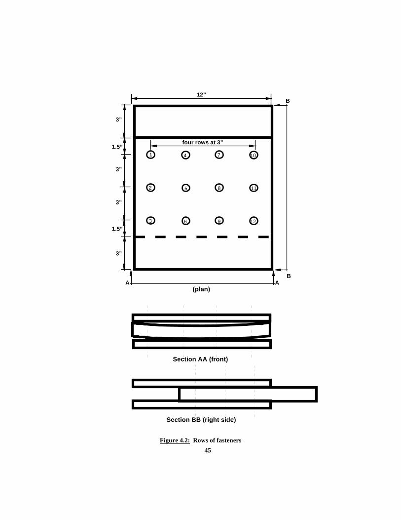
45Figure 4.2: Rows of fasteners
Section AA (front)
Section BB (right side)
1.5”
1.5”four rows at 3”
1
2
3
4
5
6
7
8
9
10
11
12
3”
3”
3”
3”
12”
AA
B
B
(plan)
46
plate. This out-of-flatness is well within the limit (9.5mm) that the ASTM A6 specification
allows for steel plates.
The three primary components of a test set-up were the bolted connection, the
support frame, and the data acquisition system. Figure 4.3 shows a typical layout of these
components. C-clamps and steel blocks braced the connection against rotation during
fastener tightening, as seen in Figure 4.4. Only the force of the tightening fasteners
influenced the joining of the plates. Each bolt in the connection had a BTM strain gauge
epoxied within the core of the unthreaded shank. Throughout the tightening sequence strain
readings were constantly recorded with the data acquisition system for computation of
fastener tensions.
The presentation of fastener tensions (test results) follows the same format for each
test. For each series of tests, summary tables indicate four statistics for each pass conducted
on the bolts. There were three possible passes for each test. The snugging pass was always
followed by a tightening pass. If the resulting tensions were low, a touch-up pass followed
the tightening pass. Of the four statistics, the first indicates the Average Final Fastener
Tension. This is the average tension that existed in all twelve fasteners upon completion of a
snugging, tightening, or touch-up pass. The second statistic identifies the average initial
tension experienced by each bolt after it was snugged, tightened, or touched-up. The third
and forth statistics show the average loss between an initial snugging, tightening, or touch-
up tension in each bolt and the final tension upon completing the pass. Specifically, the third
statistic is an average tension loss experienced by the first two rows snugged, tightened, or
touched-up. The forth statistic is the average tension loss experienced by the last two rows
snugged, tightened, or touched-up. All four statistics have their respective standard
deviations indicated.
Appendix B contains five figures per test that present tension measurements in each
bolt. The first figure shows the complete history of all bolt tensions throughout the
sequence of snugging, tightening, and touch-up during a test. The second figure is a bar
chart of final tensions for each bolt at the end of the test. The remaining three figures
graphically show the tension histories experienced by three selected fasteners. The tensile
load history of a fastener is plotted throughout a pass. The first fastener snugged is always

47
Figure 4.3: Typical test set-up: bolted connection, support frame, and data acquisition system
Figure 4.4 Support frame for bolted connection during test

48
one of the three bolts graphically represented. The pattern of tightening determines the
remaining two bolts.
Figure 4.5 illustrates the numbering template used for all tests. While this template
is the same for each test, the three patterns of tightening follow three different sequences of
tightening. The bolt numbers underlined and in bold print indicate the bolts that are
graphically presented in the tensile load history figures.
Tightening Pattern
Middle to Outside
Left to Right
Outside to Middle
Sequence of Tightening
4,5,6,7,8,9,1,2,3,10,11,12
1,2,3,4,5,6,7,8,9,10,11,12
1,2,3,10,11,12,4,5,6,7,8,9
Numbering Template
Figure 4.5: Bolt Numbering Template and Tightening Pattern Sequences
Six variables identify each of the specific tests. These variables indicate the type of
fastener, the amount of plate deformation, the tightening method used, the amount of
snugging applied before tightening, the grip thickness of the connection, and the pattern used
in tightening. The eleven digit syntax is defined below:
1st Digit: Type of fastener
C: Conventional fasteners (for all tests in this chapter)
H: Huck C50L fasteners (for all tests in Chapter 5)
2nd Digit: Plate condition
D: Deformed interior plate (for all tests)
F: Flat plates

49
3rd Digit: Middle gap created by single curvature interior plate before loading
3: 3mm gap between bent interior plate and top flat plate
6: 6mm gap between bent interior plate and top flat plate
4th & 5th Digits: Method of Installation
CW: Calibrated Wrench method
TN: Turn-of-Nut method
NS: No snug (for one Huck test only)
CS: Snug with 4 conventional fasteners before installing Huck fasteners
6th & 7th Digits: Snug tension applied before tightening method
12: 12 kip tension
25: 25 kip tension
41: 41 kip tension
8th Digit: Grip thickness of connection
2: 2 inch grip
3: 3 inch grip
4: 4 inch grip
9th - 11th Digits: Pattern of Tightening
MTO: Middle to Outside
LTR: Left to Right
OTM: Outside to Middle
The label of the first test is CD3TN122.MTO. This describes a conventional
fastener test with deformed plates (3mm). The method of tightening the fasteners was turn-
of-nut after a 12 kip snugging pass. The thickness of the grip was 2 inches (consisting of the
1 inch interior plate and the 1/2 inch thick exterior plates). The pattern of tightening was
from the middle fasteners to the outside fasteners.
4.2 3MM DEFORMED PLATES Eighteen tests involved the use of 3mm deformed plates. Prior to fastener
tightening, the 3mm gap existed between the bent interior plate and the flat exterior plate on
top. Two methods of fastener tightening joined the plates within the connection. Nine tests

50
evaluated the turn-of-nut tightening method and the remaining nine tests evaluated the
calibrated wrench tightening method. Each tightening method tested all three grip lengths
and all three patterns of tightening.
4.2.1 TURN-OF-NUT INSTALLATION METHOD The Bolt Specification states four critical conditions that must be met when using this
method. The first stipulation is that an initial snug tightening of the fasteners will bring the
deformed plates together in a “snug tight” condition. The second requirement is that fastener
tightening progress from the most rigid part of the connection (the middle two rows for
connection used in all tests) to the outside edges. The third stipulation is that subsequent
fastener loosening may require more than a single snugging pass of all fasteners. The fourth
and most critical requirement is that the method should achieve an initial minimum tension
of 39 kips in each bolt. The minimum tension of 39 kips applies to A325 bolts with a
diameter of 7/8”.
The following nine tests evaluated the effect of using a constant 12 kip tension
snugging pass followed by the stipulated rotation of the nut. No additional snugging was
applied. This is contrary to the Bolt Specification which stipulates follow on snugging
passes. A calibrated torque wrench produced a fairly consistent 12 kip tension snug. Before
each test, a Skidmore-Wilhelm bolt tension indicator verified the ability of the torque wrench
to deliver the specified 12 kip snug. By installing a minimum of 3 fastener assemblies in the
tension indicator, the setting on the adjustable torque wrench demonstrated a consistent 12
kip tension. A spud wrench with a 4 foot pipe extension, as seen in Figure 4.6, rotated the
subsequent 1/3 or 1/2 turn of the nut required. The 2” grip (3-1/4” fasteners = 3.71 bolt
diameters) required a 1/3 turn of the nut rotation after the snugging pass. The 3” grip (4-
1/4” fastener = 4.86 bolt diameters) and 4” grip (5-1/4” fastener = 6 bolt diameters) required
a 1/2 turn of the nut rotation.

51
Figure 4.6: 4 foot pipe extension for turn-of-nut tightening
Figure 4.7: 600 ft lb calibrated torque wrench used for calibrated wrench tightening

52
Two alternative tightening patterns produced results for comparison to the pattern
of progressing from the middle of the connection to the outside edges (MTO). These two
tightening patterns are described as going from left to right across the pattern (LTR) and as
going from the outside edges to the middle of the connection (OTM). All three patterns and
their respective tightening sequences appear in Figure 4.4 mentioned previously.
4.2.1.1 MIDDLE TO OUTSIDE, 12 KIP SNUG Three tests followed the middle to the outside tightening pattern, using 3mm
deformed plates applying a 12 kip snug before the turn of the nut tightening method.
CD3TN12_.MTO identifies this series of tests. The middle to outside tightening sequence is
intended to follow the requirement of progressing from the most rigid part of the connection
to the outside edges. Following the specified sequence, all twelve bolts received a 12 kip
snug with a calibrated torque wrench. The appropriate 1/3 or 1/2 turn-of-nut concluded the
tightening pass.
4.2.1.1.1 TEST RESULTS Tables 4.1 and 4.2 and Figures B.1 through B.15 summarize the results of the
CD3TN12_.MTO series of tests. Table 4.1 demonstrates an apparent decrease in final snug
fastener tension as the grip length increased. This occurred even though the average initial
snug tension was greater as the grip length increased. The average tension lost in both the
first two rows snugged and the last two rows snugged increased with greater grip thickness.
The first two rows tightened lost more tension than the last two rows tightened. This seems
to indicate that thickness of grip affects the ability of fasteners to maintain an initial snug of
12 kips.
Table 4.2 indicates similar results for the tightening pass. However, there is an
apparent discontinuity between the 2” grip and the 3” grip. This may be related to the jump
from 1/3 of a turn rotation to 1/2 of a turn rotation. The parameters for a 1/3 turn rotation
are for lengths less than or equal to four diameters, or 3.5” for 7/8” bolts. The 2” grip uses
3-1/4” bolts, very near the limit of the maximum length for 1/3 of a turn rotation. This
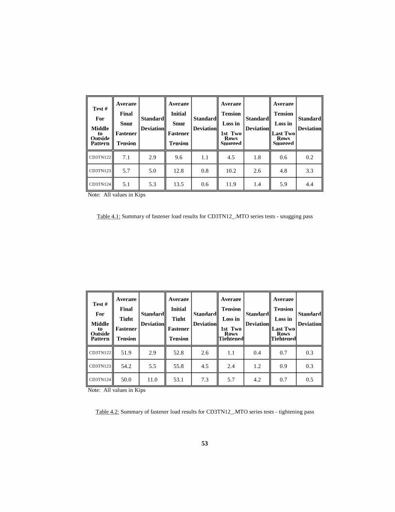
53
Average Average Average AverageTest #
Final Initial Tension TensionFor Standard Standard Standard Standard
Snug Snug Loss in Loss inMiddle Deviation Deviation Deviation Deviation
to Fastener Fastener 1st Two Last TwoOutside Rows RowsPattern Tension Tension Snugged Snugged
CD3TN122 7.1 2.9 9.6 1.1 4.5 1.8 0.6 0.2
CD3TN123 5.7 5.0 12.8 0.8 10.2 2.6 4.8 3.3
CD3TN124 5.1 5.3 13.5 0.6 11.9 1.4 5.9 4.4
Note: All values in Kips
Table 4.1: Summary of fastener load results for CD3TN12_.MTO series tests - snugging pass
Average Average Average AverageTest #
Final Initial Tension TensionFor Standard Standard Standard Standard
Tight Tight Loss in Loss inMiddle Deviation Deviation Deviation Deviation
to Fastener Fastener 1st Two Last TwoOutside Rows RowsPattern Tension Tension Tightened Tightened
CD3TN122 51.9 2.9 52.8 2.6 1.1 0.4 0.7 0.3
CD3TN123 54.2 5.5 55.8 4.5 2.4 1.2 0.9 0.3
CD3TN124 50.0 11.0 53.1 7.3 5.7 4.2 0.7 0.5
Note: All values in Kips
Table 4.2: Summary of fastener load results for CD3TN12_.MTO series tests - tightening pass

54
observation may explain the jump in average final tight fastener tension and the average
initial tight fastener tension when comparing the 2” grip and 3” grip. The average tension
loss in the 1st two rows tightened increased with grip thickness. The last two rows
experienced average losses in tension of less than 1 kip. The standard deviation for the 3”
and 4” grips indicates a large scatter in the tension values. There is an apparent increase in
this scatter with an increase in grip thickness.
Figure B.11 of test CD3TN124.MTO indicates a significant drop in the tension of
fastener #4 and fastener #6 after the completion of the tightening pass. With a snug tension
of 12 kips the thicker grip may allow a larger gap to exist between plates as compared to
thinner grips. This may be an indication of the limit of the turn-of-nut method following a
single 12 kip snugging pass. According to the Bolt Specification, the intent to the turn-of-
nut method is for a direct loading of the fastener, not the closing of a gap. Only the 4” grip
resulted in any fastener final tensions below 39 kips. Fasteners #4 and #6 were both below
39 kips at the completion of this test. The average final fastener tension, however, was well
above 39 kips.
4.2.1.2 LEFT TO RIGHT, 12 KIP SNUG Three tests followed the left to right tightening pattern, using 3mm deformed plates
applying a 12 kip snug before the turn-of-nut tightening method. CD3TN12_.LTR identifies
this series of tests. The left to right tightening sequence is in variance with the Bolt
Specification requirement of tightening from the most rigid portion of the connection to the
free edges. A calibrated torque wrench applied the 12 kip snug to all twelve bolts, followed
by the appropriate 1/3 or 1/2 turn-of-nut.
4.2.1.2.1 TEST RESULTS Tables 4.3 and 4.4 and Figures B.16 through B.30 summarize the results of the
CD3TN12_.LTR series of tests. Table 4.3 shows a decrease in Average Final Snug
Fastener Tension with an increase in grip thickness. This is more apparent between the 2”
grip and the 3” grip. The 3” and 4” grips have very similar values for final snug tensions
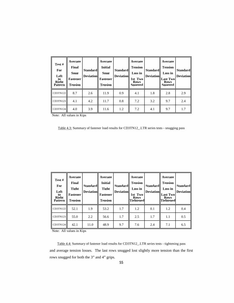
55
Average Average Average AverageTest #
Final Initial Tension TensionFor Standard Standard Standard Standard
Snug Snug Loss in Loss inLeft Deviation Deviation Deviation Deviationto Fastener Fastener 1st Two Last Two
Right Rows RowsPattern Tension Tension Snugged Snugged
CD3TN122 8.7 2.6 11.9 0.9 4.1 1.8 2.8 2.9
CD3TN123 4.1 4.2 11.7 0.8 7.2 3.2 9.7 2.4
CD3TN124 4.0 3.9 11.6 1.2 7.2 4.1 9.7 1.7
Note: All values in Kips
Table 4.3: Summary of fastener load results for CD3TN12_.LTR series tests - snugging pass
Average Average Average AverageTest #
Final Initial Tension TensionFor Standard Standard Standard Standard
Tight Tight Loss in Loss inLeft Deviation Deviation Deviation Deviationto Fastener Fastener 1st Two Last Two
Right Rows RowsPattern Tension Tension Tightened Tightened
CD3TN122 52.1 1.9 53.2 1.7 1.2 0.1 1.2 0.4
CD3TN123 55.0 2.2 56.6 1.7 2.5 1.7 1.1 0.5
CD3TN124 42.1 11.0 48.9 9.7 7.6 2.4 7.1 6.5
Note: All values in Kips
Table 4.4: Summary of fastener load results for CD3TN12_.LTR series tests - tightening pass and average tension losses. The last rows snugged lost slightly more tension than the first
rows snugged for both the 3” and 4” grips.

56
Table 4.4 shows a consistent increase in average tension loss with an increase in
grip thickness. There is a jump in the Average Final Tight Fastener Tension of the 3” grip
when compared to the 2” grip. The average tension loss of rows tightened is very low,(1-3
kips) for both the 2” and 3” grips. The 4” grip has an average tension loss of over 7 kips for
both rows.
Figure B.27 for test CD3TN124.LTR shows an interesting limit regarding the left to
right tightening pattern. Fasteners #4, #7, and #10 all fell well below the minimum final
tension of 39 kips. These fasteners were the first of their respective rows to be tightened.
4.2.1.3 OUTSIDE TO MIDDLE, 12 KIP SNUG Three tests followed the outside to middle tightening pattern, using 3mm deformed
plates applying a 12 kip snug before the turn-of-nut tightening method. CD3TN12_.OTM
identifies this series of tests. The outside to middle tightening sequence is also at variance
with the Bolt Specification requirement of tightening from the most rigid portion of the
connection to the free edges. Each test received a snugging pass of 12 kips and a tightening
pass of the appropriate 1/3 or 1/2 turn-of-nut.
4.2.1.3.1 TEST RESULTS Tables 4.5 and 4.6 and Figures B.31 through B.45 summarize the results of the
CD3TN12_.OTM series of tests. Table 4.5 shows a similar trend of decreasing average final
snug fastener tensions with an increase in grip thickness. Also, average tension loss of
snugged fasteners increased with grip thickness. While the 2” grip test had similar tension
losses for both the first two and last two rows tightened, the 3” and 4” grips had greater
losses in the first two rows tightened.
Table 4.6 reiterates the trend of increasing tension loss with increasing grip
thickness. It may be possible to think of the outside to middle tightening pattern as

57
Average Average Average AverageTest #
Final Initial Tension TensionFor Standard Standard Standard Standard
Snug Snug Loss in Loss inOutside Deviation Deviation Deviation Deviation
to Fastener Fastener 1st Two Last TwoMiddle Rows RowsPattern Tension Tension Snugged Snugged
CD3TN122 7.7 2.9 11.1 1.5 3.7 1.9 3.9 1.9
CD3TN123 4.7 3.6 11.6 1.2 8.3 2.8 6.5 3.4
CD3TN124 4.4 3.8 11.7 0.9 8.4 3.0 7.5 3.0
Note: All values in Kips
Table 4.5: Summary of fastener load results for CD3TN12_.OTM series tests - snugging pass
Average Average Average AverageTest #
Final Initial Tension TensionFor Standard Standard Standard Standard
Tight Tight Loss in Loss inOutside Deviation Deviation Deviation Deviation
to Fastener Fastener 1st Two Last TwoMiddle Rows RowsPattern Tension Tension Tightened Tightened
CD3TN122 51.8 3.3 52.6 3.6 1.0 0.5 0.9 0.2
CD3TN123 53.2 9.1 54.4 9.3 0.7 0.4 2.0 1.3
CD3TN124 39.5 20.3 46.2 14.6 8.9 8.8 5.3 3.5
Note: All values in Kips
Table 4.6: Summary of fastener load results for CD3TN12_.OTM series tests - tightening pass

58
“trapping” a gap between tightened rows. Average tension losses in the first row are more
than losses for the last row of fasteners tightened.
Figure B.42 of test CD3TN124 .OTM indicates a significant tension loss in
fasteners #10, #11, and #12. This resulted in all three being below 39 kips after the test was
completed. This outside edge of fasteners indicates that the “trapped” gap may have shifted
to the outside edge of the connection as the last two middle rows of fasteners are tightened.
4.2.1.4 TIGHTENING PATTERN COMPARISION The first nine tests of the turn-of-nut method provide comparisons between the
three tightening patterns for all three grip lengths. For the 2” grip, the difference between
the Average Initial Snug Fastener Tension and the Average Final Snug Fastener Tension
increases in the order of middle to outside (MTO), left to right (LTR) and outside to middle
(OTM). The differences are 2.5 kips, 3.2 kips, and 3.5 kips. In other words the loss of
fastener tension seems to be the greatest for the OTM pattern of tightening. The results for
the 3” grip are not in the same sequence. The OTM pattern had the least difference between
the Average Initial Snug Fastener Tension and the Average Final Snug Fastener Tension.
For the MTO, LTR, and OTM the differences are 7.1 kips, 7.7 kips, 6.9 kips respectively.
Finally, the 4” grip had the opposite trend of the 2” grip. The MTO, LTR, OTM differences
are 8.4 kips, 7.6 kips, and 7.3 kips respectively. Therefore, the results do not seem to
appreciatively favor any pattern of tightening for the snugging pass.
For the tightening pass, the 2” and 3” grips do not offer any differences greater than
1 kip between the tightening patterns. However, the 4” grip shows more than double the
tension loss for the LTR and OTM patterns when compared to the MTO pattern. The
differences between the Average Initial Tight Fastener Tensions and the Average Final Tight
Fastener Tensions are 3.1 kips, 6.8 kips, and 6.7 kips for the MTO, LTR, OTM patterns
respectively. This could be evidence in support of the Middle to Outside tightening pattern,
at least for thicker connections.
All fasteners in the 2” grip for each of the three patterns met the required 39 kip
minimum after the tightening pass. The 3” grip had only one fastener fall below the 39 kip
minimum as noted in Figure B.37 for the OTM test series. The 4” grip saw 3 fastener
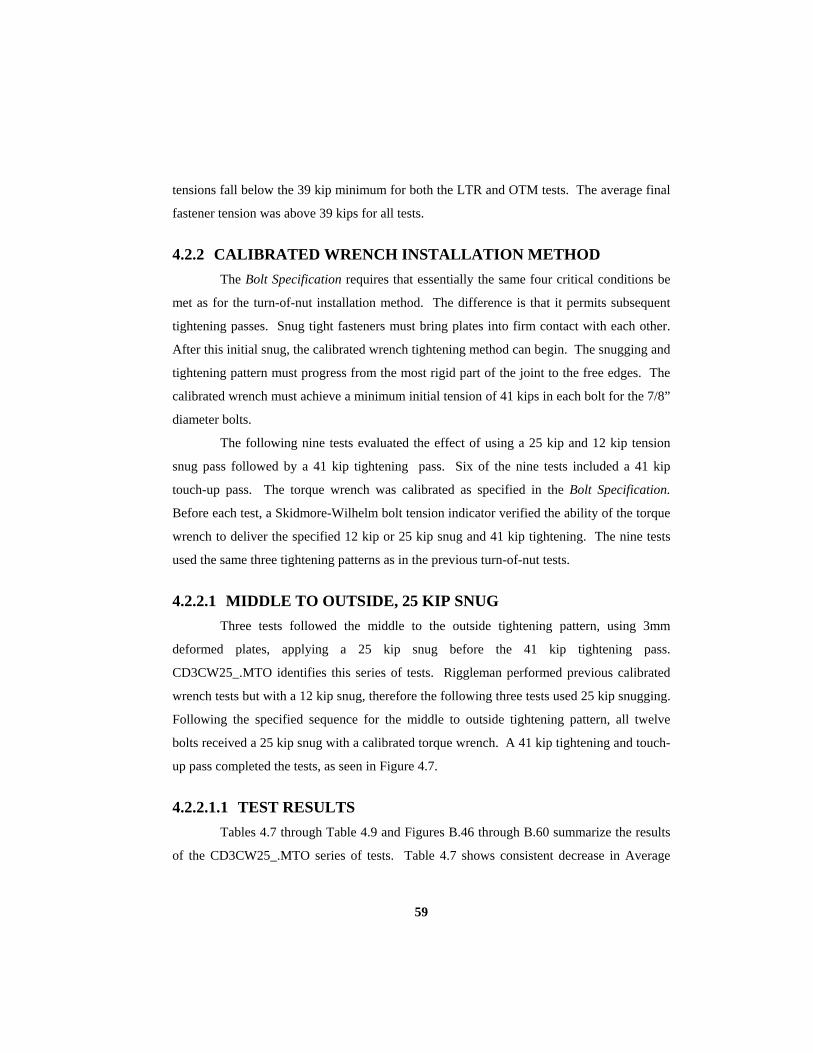
59
tensions fall below the 39 kip minimum for both the LTR and OTM tests. The average final
fastener tension was above 39 kips for all tests.
4.2.2 CALIBRATED WRENCH INSTALLATION METHOD The Bolt Specification requires that essentially the same four critical conditions be
met as for the turn-of-nut installation method. The difference is that it permits subsequent
tightening passes. Snug tight fasteners must bring plates into firm contact with each other.
After this initial snug, the calibrated wrench tightening method can begin. The snugging and
tightening pattern must progress from the most rigid part of the joint to the free edges. The
calibrated wrench must achieve a minimum initial tension of 41 kips in each bolt for the 7/8”
diameter bolts.
The following nine tests evaluated the effect of using a 25 kip and 12 kip tension
snug pass followed by a 41 kip tightening pass. Six of the nine tests included a 41 kip
touch-up pass. The torque wrench was calibrated as specified in the Bolt Specification.
Before each test, a Skidmore-Wilhelm bolt tension indicator verified the ability of the torque
wrench to deliver the specified 12 kip or 25 kip snug and 41 kip tightening. The nine tests
used the same three tightening patterns as in the previous turn-of-nut tests.
4.2.2.1 MIDDLE TO OUTSIDE, 25 KIP SNUG Three tests followed the middle to the outside tightening pattern, using 3mm
deformed plates, applying a 25 kip snug before the 41 kip tightening pass.
CD3CW25_.MTO identifies this series of tests. Riggleman performed previous calibrated
wrench tests but with a 12 kip snug, therefore the following three tests used 25 kip snugging.
Following the specified sequence for the middle to outside tightening pattern, all twelve
bolts received a 25 kip snug with a calibrated torque wrench. A 41 kip tightening and touch-
up pass completed the tests, as seen in Figure 4.7.
4.2.2.1.1 TEST RESULTS Tables 4.7 through Table 4.9 and Figures B.46 through B.60 summarize the results
of the CD3CW25_.MTO series of tests. Table 4.7 shows consistent decrease in Average

60
Average Average Average AverageTest #
Final Initial Tension TensionFor Standard Standard Standard Standard
Snug Snug Loss in Loss inMiddle Deviation Deviation Deviation Deviation
to Fastener Fastener 1st Two Last TwoOutside Rows RowsPattern Tension Tension Snugged Snugged
CD3CW252 22.6 3.0 24.3 1.9 3.2 2.4 0.2 0.2
CD3CW253 18.9 8.4 26.2 2.3 13.5 3.6 1.3 1.0
CD3CW254 11.0 8.9 25.0 1.5 20.6 5.0 9.1 5.9Note: All values in Kips
Table 4.7: Summary of fastener load results for CD3CW25_.MTO series tests - snugging pass
Average Average Average AverageTest #
Final Initial Tension TensionFor Standard Standard Standard Standard
Tight Tight Loss in Loss inMiddle Deviation Deviation Deviation Deviation
to Fastener Fastener 1st Two Last TwoOutside Rows RowsPattern Tension Tension Tightened Tightened
CD3CW252 40.9 2.0 41.4 2.1 0.7 0.1 0.5 0.1
CD3CW253 41.0 3.7 41.5 2.9 0.8 1.5 0.5 0.2
CD3CW254 40.8 3.9 42.7 3.1 3.4 2.4 0.4 0.2Note: All values in Kips
Table 4.8: Summary of fastener load results for CD3CW25_.MTO series tests - tightening pass
Average Average Average AverageTest #
Final Initial Tension TensionFor Standard Standard Standard Standard
Touch-up Touch-up Loss in Loss inMiddle Deviation Deviation 1st Two Deviation Last Two Deviation
to Fastener Fastener Rows RowsOutside Touched- Touched-Pattern Tension Tension up up
CD3CW252 42.3 1.4 42.6 1.3 0.2 0.1 0.2 0.1
CD3CW253 40.2 2.4 40.2 2.4 0.0 0.2 0.1 0.1
CD3CW254 41.3 3.3 41.5 3.5 0.4 0.0 0.2 0.1Note: All values in Kips
Table 4.9: Summary of fastener load results for CD3CW25_.MTO series tests - touch-up pass
61
Final Snug Fastener tensions as the grip thickness increased, even with a fairly consistent
Average Initial Snug Fastener Tensions. The average tension loss is dramatic in the first two
rows snugged.
Table 4.8 indicates the Average Final Tight Fastener Tensions slightly exceeded the
required 39 kips for all grips. The touch-up pass was not really necessary. The minimum 39
kip tension was developed in at least 32 of the 36 bolts tested in the three tests. The average
tension loss in the first two rows tightened is minor for all three tests. Table 4.9 shows
slight changes in the Average Final Touch-up Fastener Tensions. The 2” and 4” grips have
an increase of Average Final Touch-up Fastener Tensions while the 3” grip shows a
decrease. All changes are barely more than one kip in magnitude. There is less average
tension loss in the rows during the touch-up pass. This is expected with plates in firm
contact.
Figures B.46 through B.60 demonstrate a consistent maintenance of tension load
after the tightening pass. Of the nine Tensile Load Histories plotted for the
CD3CW25.MTO series of tests, not one shows a drop in tension below 39 kips upon
completion of the tightening pass.
4.2.2.2 LEFT TO RIGHT, 12 KIP SNUG Three tests followed the left to right tightening pattern, using 3mm deformed plates
applying a 12 kip snug before the 41 kip calibrated wrench tightening method.
CD3CW12_.LTR identifies this series of tests. These tests offer a comparison to the results
of the CD3TN12_.LTR tests. The differences are the tightening method and the fact that
the CD3TN12_.LTR tests did not have a touch-up pass. Following the specified sequence
for the left to right tightening pattern, all twelve bolts received a 12 kip snug with a
calibrated torque wrench. A 41 kip tightening and touch-up pass completed the test.
4.2.2.2.1 TEST RESULTS Table 4.10 through 4.12 and Figures B.61 through B.75 show the results of the
CD3CW12_.LTR series of tests. The snug statistics of Table 4.10 are almost the same as
those of Table 4.3. This is noted as a verification of consistency in the 12 kip snugging

62
Average Average Average AverageTest #
Final Initial Tension TensionFor Standard Standard Standard Standard
Snug Snug Loss in Loss in
Left Deviation Deviation Deviation Deviationto Fastener Fastener 1st Two Last Two
Right Rows RowsPattern Tension Tension Snugged Snugged
CD3CW122 8.9 3.3 12.5 1.6 5.1 1.8 2.5 2.6
CD3CW123 4.1 4.2 11.3 1.3 6.1 3.8 9.8 2.3
CD3CW124 4.5 3.4 11.8 0.6 6.5 2.9 9.9 1.6Note: All values in Kips
Table 4.10: Summary of fastener load results for CD3CW12_.LTR series tests - snugging pass
Average Average Average AverageTest #
Final Initial Tension TensionFor Standard Standard Standard Standard
Tight Tight Loss in Loss inLeft Deviation Deviation Deviation Deviationto Fastener Fastener 1st Two Last Two
Right Rows RowsPattern Tension Tension Tightened Tightened
CD3CW122 39.9 2.5 40.6 2.4 0.8 0.1 0.7 0.2
CD3CW123 41.7 3.7 43.7 2.2 2.9 2.6 1.3 0.8
CD3CW124 31.4 7.2 41.6 2.0 11.4 1.5 10.7 7.9Note: All values in Kips
Table 4.11: Summary of fastener load results for CD3CW12_.LTR series tests - tightening pass
Average Average Average AverageTest #
Final Initial Tension TensionFor Standard Standard Standard Standard
Touch-up Touch-up Loss in Loss inLeft Deviation Deviation 1st Two Deviation Last Two Deviationto Fastener Fastener Rows Rows
Right Touched- Touched-Pattern Tension Tension up up
CD3CW122 41.6 2.7 41.7 2.7 0.2 0.0 0.1 0.0
CD3CW123 43.2 3.3 43.2 3.3 0.0 0.1 0.0 0.1
CD3CW124 40.1 2.8 40.4 2.6 0.5 0.4 0.2 0.2Note: All values in Kips
Table 4.12: Summary of fastener load results for CD3CW12_.LTR series tests - touch-up pass
63
pass. For the first tightening pass of the 4” grip, Table 4.11 indicates an Average Final
Tight Fastener Tension 7.6 kips below the minimum of 39 kips. Only the last three fasteners
of the tightening pass held a tension above 39 kips for the 4” grip. The calibrated wrench
method does not supply much tension beyond it’s intended 41 kip load. Riggleman had
similar results for the first tightening pass of his 12 kip snug, calibrated wrench test. As
expected for the 4” grip, the average tension loss in the first and second rows tightened is
greater than that of the 2” and 3” grips.
As recommended by the Bolt Specification, Table 4.12 indicates that the Average
Final Touch-up Fastener Tension meets the 39 kip requirement for all grips. However, even
after this touch-up pass, there was one bolt below the 39 kip minimum for the 2” and 3”
grips. There were four bolts that were just below the 39 kip tension for the 4” grip.
4.2.2.3 OUTSIDE TO MIDDLE, 12 KIP SNUG Three tests followed the outside to middle tightening pattern, using 3mm deformed
plates applying a 12 kip snug before the 41 kip calibrated wrench tightening method.
CD3CW12_.OTM identifies this series of tests. Following the sequence for the outside to
middle tightening pattern, all twelve bolts received a 12 kip snug with a calibrated torque
wrench. A 41 kip tightening pass completed the test. A touch-up pass was not conducted.
4.2.2.3.1 TEST RESULTS Tables 4.13 through 4.14 and Figures B.76 through B.90 show the results of the
CD3CW12_.OTM series of tests. An increase in grip thickness caused increased tension
loss after the snugging pass. Most tension loss was in the first two rows tightened (on the
outside). The tightening pass reflects the same trend as the snugging pass. The Average
Final Tight Fastener Tensions for the 2” and 3” grips are above 39 kips. After the tightening
pass the 2" grip had one fastener that did not maintain the 39 kip minimum. The 3" and 4"
grips had 4 and 8 fasteners, respectively, that did not maintain the 39 kip minimum. The
Average Final Tight Fastener Tension for the 4” grip is 37 kips. The 4” grip clearly needed
a touch-up pass, however this was not conducted.

64
Average Average Average AverageTest #
Final Initial Tension TensionFor Standard Standard Standard Standard
Snug Snug Loss in Loss inOutside Deviation Deviation Deviation Deviation
to Fastener Fastener 1st Two Last TwoMiddle Rows RowsPattern Tension Tension Snugged Snugged
CD3CW122 8.6 2.3 11.6 1.2 2.8 1.6 3.7 2.0
CD3CW123 5.4 3.9 11.8 1.0 7.8 2.2 6.0 3.0
CD3CW124 4.4 4.2 12.4 0.9 8.9 2.3 8.5 3.3
Note: All values in Kips
Table 4.13: Summary of fastener load results for CD3CW12_.OTM series tests - snugging pass
Average Average Average AverageTest #
Final Initial Tension TensionFor Standard Standard Standard Standard
Tight Tight Loss in Loss inOutside Deviation Deviation Deviation Deviation
to Fastener Fastener 1st Two Last TwoMiddle Rows RowsPattern Tension Tension Tightened Tightened
CD3CW122 40.9 2.5 41.4 2.5 0.8 0.1 0.4 0.1
CD3CW123 39.9 3.9 40.9 3.1 0.3 0.2 2.2 1.8
CD3CW124 37.0 4.2 42.6 2.3 6.4 2.6 5.8 3.3
Note: All values in Kips
Table 4.14: Summary of fastener load results for CD3CW12_.OTM series tests - tightening pass

65
4.2.2.4 TIGHTENING PATTERN COMPARISION The first nine tests of the calibrated wrench method provide comparisons between
the three tightening patterns for all three grip lengths. Because the middle to outside (MTO)
tests (CD3CW25_.MTO) used a 25 kip snug, Riggleman’s CDCW series tests (12 kip snug)
will be used for the MTO comparison to the LTR and OTM tightening patterns. The
CD3CW25_.MTO series of tests permit evaluation of the difference between the 12 and 25
kips snugging for the MTO pattern. This will be discussed at the end of this section.
For the 2” and 3” grips, the difference between the Average Initial Snug Fastener
Tension and the Average Final Snug Fastener Tension does not vary more than 1.5 kips
between the MTO, LTR and OTM patterns. However, both the 2” and 3” grip indicate the
most tension loss for the LTR pattern. The 4” grip tests show that the LTR and OTM
patterns lost more tension than the MTO pattern of tightening. The differences between the
Average Initial Snug Fastener Tensions and the Average Final Snug Fastener Tensions are
6.4 kips, 7.4 kips, and 8.0 kips for MTO, LTR, and OTM respectively. The results do not
seem to appreciatively favor any pattern of tightening for the snugging pass. With a
comparison to the snugging pass of the turn-of-nut method, there does not seem to be any
trend for which pattern sustains the most tension after the 12 kip snug pass.
For the tightening pass, the 2” and 3” grips do not offer any differences between the
tightening patterns that exceed 1 kip. However, the 4” grip shows nearly double the tension
loss for the MTO and LTR patterns when compared to the OTM pattern. The differences
between the Average Initial Tight Fastener Tensions and the Average Final Tight Fastener
Tensions are 10.1 kips, 10.2 kips, and 5.6 kips for the MTO, LTR, OTM patterns
respectively. This could be evidence in support of the Outside to Middle tightening pattern,
at least for thicker connections. This is contrary to the findings of the turn-of-nut series of
tests.
For Riggleman’s MTO pattern of tests, the 2” grip had four fasteners under the
required 39 kip minimum after the tightening pass. The 3” and 4” grip MTO tests had 10
and 8 fasteners, respectively, below the 39 kip minimum. The 2”, 3” and 4” grips for the
LTR pattern of tightening had 2, 2, and 9 fasteners fall below the 39 kip minimum,
respectively. The OTM pattern of tightening faired slightly better with the 2” , 3” and 4”
grips having 1, 4, and 8 fasteners, respectively, below the 39 kip minimum. This is another
66
way to look at the results supporting the OTM pattern for the calibrated wrench tightening
method.
When comparing the 12 kip and 25 kip snug for the MTO tightening pattern, there
are clear indications of which provides a higher final fastener tension . The 2” and 3” grips
show similar tension losses to within 1-2 kips for both the snugging and tightening passes.
The Average Final Tight Fastener Tensions are higher for the 25 kip snug pass. The 2”, 3”
and 4” grip Average Final Fastener Tensions are 39.5, 35.4, and 30.4 for the 12 kip snug as
compared to 40.9, 41.0, and 40.8 for the 25 kip snug.
4.2.3 TIGHENING METHOD COMPARISION All the average final snug fastener tensions are fairly similar between the two
tightening methods. This is expected since the snugging pass is independent of the
subsequent tightening pattern. The Average Final Tight Fastener Tensions were
consistently higher for the turn-of-nut method. The turn-of-nut method averaged between
2.6 and 13.3 kips higher Average Final Tight Fastener Tensions for the 18 tests conducted.
All turn-of-nut methods produced Average Final Tight Fastener Tensions above 39 kips.
The calibrated wrench method resulted in 2 tests averaging below 39 kips. Both were with
the 4” grip.
4.3 6MM DEFORMED PLATES Seven tests involved the use of 6mm deformed plates. Prior to fastener tightening,
the 6mm gap existed between the bent interior plate and the flat exterior plate on top. Two
methods of fastener tightening joined the plates within the connection. Three tests
evaluated the turn-of-nut tightening method using 2”, 3”, and 4” grips. Four tests evaluated
the calibrated wrench tightening method using only the 3” and 4” grips.
4.3.1 TURN-OF-NUT INSTALLATION METHOD The three tests with the 6mm gap used the same turn-of-nut method described in
section 4.2.1. However, the “snug tight” intent of the Bolt Specification became very
apparent. Two tests (the 2” and 3” grips) used a single snug pass of 12 kips. The 3” grip
produced an average final tight fastener tension well below the minimum tension of 39 kips.

67
The 4” grip test followed the Bolt Specification more closely by snugging the fasteners to
where the plates appeared to be in firm contact. The fasteners received a total of 3 snugging
passes. The first snugging pass was with a calibrated wrench set at 25 kips. The second and
third passes consisted of a 1/6 rotation of the nut for each pass. The intent was to bring the
plates into visible contact.
Before each test, a Skidmore-Wilhelm bolt tension indicator verified the ability of
the torque wrench to deliver the specified 12 kip or 25 kip snug. By installing a minimum of
3 fastener assemblies in the tension indicator, the torque wrench was calibrated. A spud
wrench with a 4 foot pipe extension rotated the subsequent 1/3 or 1/2 turn-of -nut required.
The 2” grip required a 1/3 turn of the nut rotation after the snugging pass. The 3” and 4”
grips required a 1/2 turn of the nut rotation. The tests with the 6mm gap plates used only the
middle to outside tightening pattern.
4.3.1.1 MIDDLE TO OUTSIDE, 12 KIP SNUG Two tests followed the middle to the outside tightening pattern, using 6mm
deformed plates applying a 12 kip snug before the turn-of-nut tightening method.
CD6TN12_.MTO identifies this series of tests. The middle to outside tightening sequence is
intended to follow the requirement of progressing from the most rigid part of the connection
to the outside edges. Following the specified sequence, all twelve bolts received a 12 kip
snug with a calibrated torque wrench. The appropriate 1/3 or 1/2 turn-of-nut concluded the
tightening pass for the 2” and 3” grip tests, respectively.
4.3.1.1.1 TEST RESULTS Tables 4.15 through 4.17 and Figures B.91 through B.100 summarize the results of
the CD6TN12_.MTO series of tests. Table 4.15 indicates that the thicker the grip the lower
the Average Final Snug Fastener Tension. Most of the tension was lost in the first two rows
tightened.
Table 4.16 demonstrates similar results for the tightening pass. However, the
tension lost in the 3” grip was very substantial, resulting in an Average Final Tight Fastener
Tension of only 4.9 kips. The 12 kip snug did little to bring the plates into a “snug-tight”
condition. Even another 1/2 turn-of-nut produced a low 23.3 kip Average Final Touch-up

68
Fastener Tension as indicated in Table 4.17. Both the 1st tightening pass and 2d tightening
had Average Initial Fastener Tensions below the 41 kip requirement. Apparently, the 1/2
turn-of-nut was simply continuing to close the gap instead of applying sustainable tensions
to the fasteners.
This is a clear indication of the importance of more than one snugging pass to bring
the plates into firm contact before attempting the turn-of-nut tightening method. The next
test with the 4” grip explores the multiple snugging pass procedure.
4.3.1.2 MIDDLE TO OUTSIDE, “CODE” SNUG CD6TN254.MTO identifies this test. This test attempted to follow the Bolt
Specification’s criteria of having a “snug tight” condition before beginning the turn-of-nut
method. The middle to the outside tightening pattern was used. The middle plate had a
6mm gap in singular curvature. Initially, a 25 kip snug was applied to the fasteners.
Following this, two incremental 1/6 turn-of-nut snugging passes brought the plates into
visual contact. The result of the two 1/6 turns is called the visual snug pass. The code
specifies that the plates should be in firm contact. A discussion of the test results will
indicate that plates in visual contact may not be in firm contact. One tightening pass of 1/2
turn-of-nut rotation followed the apparent visual “snug-tight” condition. It should be noted
that all information on this test is presented in the form of three passes: the 25 kip snug pass,
the visual snug pass, and the tightening pass.
4.3.1.2.1 TEST RESULTS Tables 4.18 through Table 4.20 and Figures B.101 through B.105 summarize the
results of the CD6TN254.MTO test. The first snugging pass resulted in an average final
snug fastener tension of 7.5 kips. However, the first two rows tightened lost practically all

69
Average Average Average AverageTest #
Final Initial Tension TensionFor Standard Standard Standard Standard
Snug Snug Loss in Loss inMiddle Deviation Deviation Deviation Deviation
to Fastener Fastener 1st Two Last TwoOutside Rows RowsPattern Tension Tension Snugged Snugged
CD6TN122 5.9 4.2 11.5 2.0 8.5 2.4 3.2 2.2
CD6TN123 3.8 4.4 11.1 1.2 10.7 1.4 4.6 4.7Note: All values in Kips
Table 4.15: Summary of fastener load results for CD6TN12_.MTO series tests - snugging pass
Average Average Average AverageTest #
Final Initial Tension TensionFor Standard Standard Standard Standard
Tight Tight Loss in Loss inMiddle Deviation Deviation Deviation Deviation
to Fastener Fastener 1st Two Last TwoOutside Rows RowsPattern Tension Tension Tightened Tightened
CD6TN122 40.2 17.5 42.0 16.2 2.9 2.1 0.9 0.2
CD6TN123 4.9 5.0 14.6 4.8 14.2 4.0 6.1 4.8Note: All values in KipsTable 4.16: Summary of fastener load results for CD6TN12_.MTO series tests - 1st tightening pass
Average Average Average AverageTest #
Final Initial Tension TensionFor Standard Standard Standard Standard
Touch-up Touch-up Loss in Loss inMiddle Deviation Deviation 1st Two Deviation Last Two Deviation
to Fastener Fastener Rows RowsOutside Touched- Touched-Pattern Tension Tension up up
CD6TN122 N/A N/A N/A N/A N/A N/A N/A N/A
CD6TN123 23.3 17.4 31.6 16.0 14.4 2.2 2.6 3.5Note: All values in KipsTable 4.17: Summary of fastener load results for CD6TN12_.MTO series tests - 2d tightening pass
of the initial 25 kip snug tension applied. The second snugging pass showed improvements
in the ability to sustain a snug load. However, Table 4.20 indicates that even though an

70
average initial tight fastener tension was 44.1 kips, there was enough tension loss to result in
an average final tight fastener tension of only 35.4 kips. Six of the 12 fasteners were well
below the 39 kip minimum tension. This is shown in Figure B.102.
4.3.2 CALIBRATED WRENCH INSTALLATION METHOD Essentially, the same application of the calibrated wrench method of tightening as
described in section 4.2.2 was applied for 4 more tests. The 6mm gap was the main
difference from the previous tests. In an attempt to handle this increased gap, a 25 kip
snugging pass was used for two of the four tests. The snugging and tightening pattern
progressed from the most rigid part of the joint to the free edges (MTO). The calibrated
wrench method attempted to achieve a minimum tightening pass tension of 41 kips in each
bolt.
The following four tests evaluated the effect of using the set 12 kip and 25 kip
tension snug pass followed by a 41 kip tightening pass. All tests included a 41 kip touch-up
pass. The torque wrench was calibrated as specified in the Bolt Specification. Before each
test, a Skidmore-Wilhelm bolt tension indicator verified the ability of the torque wrench to
deliver the specified 12 kip or 25 kip snug and 41 kip tightening. The four tests used the
same tightening pattern of middle to outside.
4.3.2.1 MIDDLE TO OUTSIDE, 12 KIP SNUG Two tests followed the middle to the outside tightening pattern, using 6mm
deformed plates, applying a 12 kip snug before the 41 kip tightening pass.
CD6CW12_.MTO identifies this series of tests. A 41 kip touch-up pass completed each test.
The tests used only the 3” and 4” grips.

71
Average Average Average AverageTest #
Final Initial Tension TensionFor Standard Standard Standard Standard
Snug Snug Loss in Loss inMiddle Deviation Deviation Deviation Deviation
to Fastener Fastener 1st Two Last TwoOutside Rows RowsPattern Tension Tension Snugged Snugged
CD6TN254 7.5 10.4 25.6 3.6 25.0 4.4 13.4 9.4Note: All values in Kips
Table 4.18: Summary of fastener load results for CD6TN254.MTO test - 25k snug pass
Average Average Average AverageTest #
Final Initial Tension TensionFor Standard Standard Standard Standard
Re-Snug Re-Snug Loss in Loss inMiddle Deviation Deviation Deviation Deviation
to Fastener Fastener 1st Two Last TwoOutside Rows RowsPattern Tension Tension Re- Re-
Snugged SnuggedCD6TN254 13.0 15.2 17.5 13.2 6.4 1.9 3.0 3.2Note: All values in Kips
Table 4.19: Summary of fastener load results for CD6TN254.MTO series tests - visual snug pass
Average Average Average AverageTest #
Final Initial Tension TensionFor Standard Standard Standard Standard
Tight Tight Loss in Loss inMiddle Deviation Deviation 1st Two Deviation Last Two Deviation
to Fastener Fastener Rows RowsOutside Tightened TightenedPattern Tension Tension
CD6TN254 35.4 18.1 44.1 13.4 13.6 4.8 4.5 6.2Note: All values in Kips
Table 4.20: Summary of fastener load results for CD6TN254.MTO series tests - tightening pass

72
4.3.2.1.1 TEST RESULTS Table 4.21 through 4.23 and Figures B.106 through B.115 show the results of the
CD6CW12_.MTO series of tests. For the snugging pass the Average Final Snug Fastener
Tensions reflect the Average Initial Snug Fastener Tension. The 4” grip has an Average
Final Snug Fastener Tension of about 1 kip more than the 3” grip. The Average Initial Snug
Fastener Tension is also 1 kip greater for the 4” grip compared to the 3” grip. Tensions lost
were essentially the same between the two grips. Most tension loss occurred in the first two
rows tightened.
Tables 4.22 and 4.23 indicate that the 4” grip had an average final tight and touch-
up fastener tensions that were 6 and 3 kips lower than the 3” grip. Most tension loss
occurred in the first two rows tightened. Figure B.112 shows that six fasteners are below the
39 kip minimum. It would seem that the Average Final Tight Fastener Tension of 23 kips,
after the tightening pass should qualify as a “snug tight” condition. However, it should be
noted that Figure B.111 of Fastener Tensions shows that four of twelve fasteners are below
15 kips.
4.3.2.2 MIDDLE TO OUTSIDE, 25 KIP SNUG Two tests followed the middle to the outside tightening pattern, using 6mm
deformed plates, applying a 25 kip snug before the 41 kip tightening pass.
CD6CW25_.MTO identifies this series of tests. A 41 kip touch-up pass completed each test.
The tests used only the 3” and 4” grips.

73
Average Average Average AverageTest #
Final Initial Tension TensionFor Standard Standard Standard Standard
Snug Snug Loss in Loss inMiddle Deviation Deviation Deviation Deviation
to Fastener Fastener 1st Two Last TwoOutside Rows RowsPattern Tension Tension Snugged Snugged
CD6CW123 3.4 4.6 11.0 1.2 10.8 1.7 5.2 4.6
CD6CW124 4.5 5.2 12.1 0.9 10.8 1.5 5.3 5.4Note: All values in Kips
Table 4.21: Summary of fastener load results for CD6CW12_.MTO series tests - snugging pass
Average Average Average AverageTest #
Final Initial Tension TensionFor Standard Standard Standard Standard
Tight Tight Loss in Loss inMiddle Deviation Deviation Deviation Deviation
to Fastener Fastener 1st Two Last TwoOutside Rows RowsPattern Tension Tension Tightened Tightened
CD6CW123 29.0 12.3 42.1 3.5 23.4 4.4 3.3 1.4
CD6CW124 23.0 15.2 42.4 3.5 30.8 6.1 9.6 6.3Note: All values in Kips
Table 4.22: Summary of fastener load results for CD6CW12_.MTO series tests - tightening pass
Average Average Average AverageTest #
Final Initial Tension TensionFor Standard Standard Standard Standard
Touch-up Touch-up Loss in Loss inMiddle Deviation Deviation 1st Two Deviation Last Two Deviation
to Fastener Fastener Rows RowsOutside Touched- Touched-Pattern Tension Tension up up
CD6CW123 42.0 3.9 42.7 3.6 1.3 0.5 0.2 0.2
CD6CW124 38.9 5.2 39.9 4.6 1.6 0.9 0.2 0.1Note: All values in Kips
Table 4.23: Summary of fastener load results for CD6CW12_.MTO series tests - touch-up pass

74
4.3.2.2.1 TEST RESULTS Tables 4.24 through 4.26 and Figures B.116 through B.125 summarize the results
of the CD6CW25_.MTO series of tests. Table 4.24 shows consistent decrease in Average
Final Snug Fastener Tensions as the grip thickness increased, even with the same Average
Initial Snug Fastener Tensions. The average tension loss was extensive in the first two rows
snugged.
Table 4.25 indicates up to code average final tight fastener tensions for the 3” grip
only. The 4” grip depended on the touch-up pass to go from 36.4 kips to 41.9 kips. After
the touch-up passes only one fastener in each grip was below the 39 kip minimum. There
was less average tension loss in the rows after the touch-up pass. This is expected with
plates in firm contact.
4.3.2.3 KIP & 25 KIP SNUG COMPARISON The 25 kip snug produced higher average final fastener tensions for all three passes
when compared to the 12 kip snug. However, only the 3” grip met the minimum
requirement of 39 kip average after the first tightening pass using the 25 kip snug. Both the
3” and 4” grips using a 12 kip snug and the 4” grip using the 25 kip snug needed the touch-
up pass to get close to the minimum of 39 kips. The 4” grip with the 12 kip snug actually
only averaged 38.9 kips after this touch-up pass. Tension loss primarily came from the first
two rows tightened. The 25 kip snug tests showed much lower tension loss during the first
tightening pass when compared to the 12 kip snug tests.
4.3.3 TIGHTENING METHOD COMPARISION Of the seven tests conducted with 6mm gap plates, four offer a comparison of the
two tightening methods (turn-of-nut and calibrated wrench). CD6TN123.MTO and
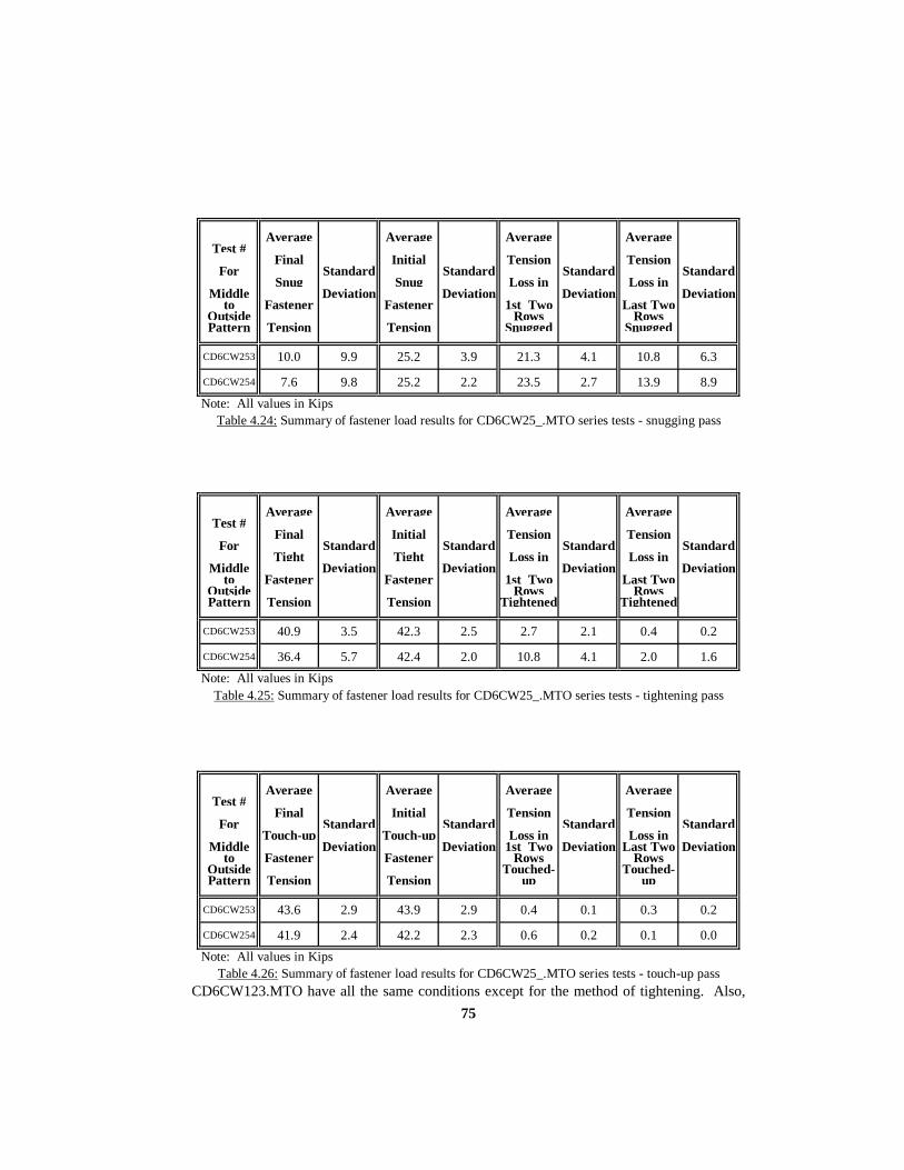
75
Average Average Average AverageTest #
Final Initial Tension TensionFor Standard Standard Standard Standard
Snug Snug Loss in Loss inMiddle Deviation Deviation Deviation Deviation
to Fastener Fastener 1st Two Last TwoOutside Rows RowsPattern Tension Tension Snugged Snugged
CD6CW253 10.0 9.9 25.2 3.9 21.3 4.1 10.8 6.3
CD6CW254 7.6 9.8 25.2 2.2 23.5 2.7 13.9 8.9Note: All values in Kips
Table 4.24: Summary of fastener load results for CD6CW25_.MTO series tests - snugging pass
Average Average Average AverageTest #
Final Initial Tension TensionFor Standard Standard Standard Standard
Tight Tight Loss in Loss inMiddle Deviation Deviation Deviation Deviation
to Fastener Fastener 1st Two Last TwoOutside Rows RowsPattern Tension Tension Tightened Tightened
CD6CW253 40.9 3.5 42.3 2.5 2.7 2.1 0.4 0.2
CD6CW254 36.4 5.7 42.4 2.0 10.8 4.1 2.0 1.6Note: All values in Kips
Table 4.25: Summary of fastener load results for CD6CW25_.MTO series tests - tightening pass
Average Average Average AverageTest #
Final Initial Tension TensionFor Standard Standard Standard Standard
Touch-up Touch-up Loss in Loss inMiddle Deviation Deviation 1st Two Deviation Last Two Deviation
to Fastener Fastener Rows RowsOutside Touched- Touched-Pattern Tension Tension up up
CD6CW253 43.6 2.9 43.9 2.9 0.4 0.1 0.3 0.2
CD6CW254 41.9 2.4 42.2 2.3 0.6 0.2 0.1 0.0Note: All values in Kips
Table 4.26: Summary of fastener load results for CD6CW25_.MTO series tests - touch-up passCD6CW123.MTO have all the same conditions except for the method of tightening. Also,
76
CD6TN254.MTO and CD6CW254.MTO will be compared. All tests included touch-up
passes.
For the 3” grip with 12 kip snug, the average snug tensions and tension losses are
the same, as expected. However, the tightening pass shows a definite difference in values.
The Average Final Tight Fastener Tension for the turn-of-nut method is well below the value
for the calibrated wrench method. The Average Initial Tight Tension of 14.6 kips is well
below the 42.1 kips of the calibrated wrench method. This indicates that the “snug
tight” condition is critical to the turn-of-nut method. This concept is reinforced in the touch-
up pass also.
The 25 kip snug tests indicate the same results. Even though 25 kips were used to
snug, the turn-of-nut method never achieves an average final touch-up fastener tension over
39 kips. This might be interpreted as a benefit in using the calibrated wrench method for the
larger deformed plates.
4.4 PLATE DEFORMATION COMPARISON The 3mm gap tests seem to support the turn-of-nut method and perhaps the middle
to outside tightening pattern for at least the thicker grip of 4”. All average final tight
fastener tensions were greater for the turn-of-nut method.
The 6mm gap tests support the calibrated wrench method over the turn-of-nut
method. However, the reason is due to the ambiguity in obtaining a “snug-tight” condition.
While the calibrated wrench method guarantees average initial tight fastener tensions of
about 41 kips, the turn-of-nut offers no such guarantee if the plates are not in firm contact.
The 6mm gap clearly exposes the need for firm plate contact. A single snug pass or even the
appearance of “snug tight” does not qualify as firm contact.

77
5. CHAPTER 5 CONNECTION TESTS WITH HUCK C50L FASTENERS
5.1 GENERAL The final 4 tests consisted of Huck International C50L lock-pin and collar
fasteners. The tests evaluated the same grip lengths as the previous tests that used
conventional fasteners. The Huck fasteners were also 7/8” in diameter
(part #C50LFR-DBR28) and of three lengths. The fasteners had grip numbers 28, 44, and 60
corresponding to the 2”, 3”, and 4” length grips. All lock-pins were mechanically
galvanized. Non-galvanized collars secured the lock-pins to form the connection.
Twelve fasteners connected three plates of ASTM A572 Grade 50 steel, producing
a slip-critical lap splice connection. Three connection grips were evaluated. Figure 5.1
identifies the three fastener lengths and their respective connection (grip) grips. Referring
back to Figure 4.2 reiterates the dimensions of the connection and the numbered rows of
fasteners.
Grip Number
Total Grip
(inches)
Thickness of
Interior Plate
(inches)
Thickness of
Exterior Plates
(inches)
28 2 1 1/2
44 3 1-1/2 3/4
60 4 2 1
Figure 5.1: Fastener Lengths and Grip Thickness
All tests involved a deformed interior plate. As described in Chapter 2, the single
curvature interior plate produced a 3mm or 6mm gap between itself and the top exterior
plate. This out-of-flatness is well within the maximum gap (9.5mm) that the ASTM A6
specification allows for milled steel plates.

78
The three primary components of a test set-up were the same as for the
conventional fastener tests. C-clamps and steel blocks braced the connection against
movement during fastener installation. Only the force of the tensioned fasteners influenced
the joining of the plates. Each lock-pin in the connection had a BTM strain gauge epoxied
within the core of the unthreaded shank. Throughout the installation sequence strain
readings were constantly recorded with the data acquisition system for future computation of
fastener tensions.
The presentation of fastener tensions (test results) follows the same general format
as for the conventional fastener tests conducted. The primary difference is that only one
pass of fastener tightening was conducted. Therefore, there is only one table for each series
of tests. For the Huck fasteners, one pass means that installation did not involve any
partial swaging of the collar. However, three tests incorporated a temporary snugging of the
plates using “snug-up” conventional fasteners before lock-pin and collar fasteners were
installed. The forth test had no snugging of the plates prior to complete lock-pin and collar
installation.
For each series of tests, the one summary table indicates the same final four
statistics as calculated for the conventional fastener tests. Of the four statistics, the first
indicates the Average Final Fastener Tension. This is the average tension that existed in all
twelve fasteners upon completion of installation pass. The second statistic identifies the
average initial tension experienced by each fastener right after it was installed. The third
and forth statistics show the average loss in tension between the initial installation tension in
each fastener and the final tension upon installing all twelve fasteners. Specifically, the third
statistic is an average tension loss experienced by the first two rows installed. These first
two rows were always the two interior rows for these tests. The forth statistic is the average
tension loss experienced by the last two rows installed. The last two rows were the exterior
rows. All four statistics have their respective standard deviations indicated.
In Appendix C, five figures for each test present fastener by fastener tensions. The
first figure shows the complete history of all fastener tensions throughout the sequence of
installation. The second figure is a bar chart of final tensions for each fastener at the end of
the test. The remaining three figures graphically show all the tensions experienced by three
selected fasteners. This tensile load history of a fastener is plotted throughout the

79
installation of all fasteners. The first fastener installed is always one of the three bolts
graphically represented. Fasteners #8 and #2 are the other two fasteners plotted, as per all
the other middle to outside tightening pattern tests.
Figure 5.2 illustrates the numbering template used for all tests. For the three tests
involving the 4 conventional fastener snug, the letters a, b, c, and d indicate the four bolts
used to bring the plates together in an attempted snug-tight condition. The one test that
involved no snugging uses the same numbering template, excluding the letters a,b,c, and d.
The pattern of installation for all tests follows the middle to outside sequence, going from the
most rigid part to the connection to the free edges. The fastener numbers underlined and in
bold print indicate the fasteners that are graphically presented in the tensile load history
figures.
Installation Pattern
Conventional Fasteners for
Snug
Huck Fasteners (* = removal of Conventional
Fasteners)
Sequence of Installation
a, b, c, d
5, a*, 4, b*, 6, c*, 7, 8, d*,9,
1,2,3,10,11,12
Numbering Template
Figure 5.2: Fastener Numbering Template Installation Sequences
The same six variables identify each of the specific tests. These variables indicate
the type of fastener, the amount of plate deformation, the tightening method used, the
amount of snugging applied before tightening, the grip thickness of the connection, and the
pattern used in tightening. For the four tests conducted with Huck fasteners, the eleven digit
syntax is defined below:
1st Digit: Type of fastener
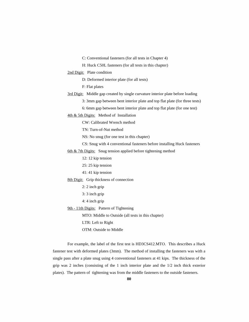
80
C: Conventional fasteners (for all tests in Chapter 4)
H: Huck C50L fasteners (for all tests in this chapter)
2nd Digit: Plate condition
D: Deformed interior plate (for all tests)
F: Flat plates
3rd Digit: Middle gap created by single curvature interior plate before loading
3: 3mm gap between bent interior plate and top flat plate (for three tests)
6: 6mm gap between bent interior plate and top flat plate (for one test)
4th & 5th Digits: Method of Installation
CW: Calibrated Wrench method
TN: Turn-of-Nut method
NS: No snug (for one test in this chapter)
CS: Snug with 4 conventional fasteners before installing Huck fasteners
6th & 7th Digits: Snug tension applied before tightening method
12: 12 kip tension
25: 25 kip tension
41: 41 kip tension
8th Digit: Grip thickness of connection
2: 2 inch grip
3: 3 inch grip
4: 4 inch grip
9th - 11th Digits: Pattern of Tightening
MTO: Middle to Outside (all tests in this chapter)
LTR: Left to Right
OTM: Outside to Middle
For example, the label of the first test is HD3CS412.MTO. This describes a Huck
fastener test with deformed plates (3mm). The method of installing the fasteners was with a
single pass after a plate snug using 4 conventional fasteners at 41 kips. The thickness of the
grip was 2 inches (consisting of the 1 inch interior plate and the 1/2 inch thick exterior
plates). The pattern of tightening was from the middle fasteners to the outside fasteners.

81
5.2 3MM DEFORMED PLATES Three tests involved the use of 3mm deformed plates. Prior to fastener installation,
the 3mm gap existed between the bent interior plate and the flat exterior plate on top. Four
conventional fasteners with 41 kips of tension brought the plates together before the
installation of the Huck fasteners, as seen in Figure 5.3. The tests evaluated each of the three
grip lengths. All three tests used the middle to outside tightening pattern.
5.2.1 SINGLE PASS INSTALLATION METHOD, WITH CONVENTIONAL BOLT SNUG
As noted by Riggleman, deformed plates present a significant challenge to the lock-
pin and collar fastener. Partial swaging of the collar, in an attempt to produce a “snug-tight”
condition in the plates, introduces a limit on the fastener's ability to close the gap upon
further swaging. Once the first few grooves of a collar are swaged, subsequent full swaging
must begin at the point of initial swaging. Swaging can only extend the finite length of the
collar. A gap may still exist after full swaging. The values of Average Final Tight Tension
for Riggleman's tests with partial swage snugging were 34.6 kips, 37.9 kips, and 33.1 kips
for the 2", 3", and 4" grips. It represented a slight improvement over the tests that involved
no snugging (38.9 kips, 32.5 kips, and 31.5 kips).
In an effort to follow the Bolt Specification, the four conventional fasteners with 41
kips of tension required a few passes with a torque wrench to bring the plates into firm
contact. Before each test, a Skidmore-Wilhelm bolt tension indicator verified the ability of
the torque wrench to deliver the specified 41 kip snug. During the snugging process,
tensions were monitored to indicate the need for subsequent passes. However, without a
monitoring device a few passes with a calibrated wrench will ensure a 41 kip tension in all
bolts. Once all four conventional fasteners had 41 kips of tension, the Huck fasteners were
installed. The intent was to avoid beginning the swaging process until a "snug-tight"
condition existed. Figure 5.3 shows the first Huck fastener just before swaging.
The following three tests evaluated the effectiveness of using the 4 conventional
bolt snug. Huck fasteners systematically filled the open holes or replaced the conventional
fasteners one at a time using one pass of complete swaging. The Bolt Specification requires
the same initial minimum tension of 41 kips in each fastener. This initial tension is 5%

82
greater than the minimum tension of 39 kips required of all fasteners in the connection after
the completion of the installation pass. The sequence of installation is described above in
Figure 5.2.
5.2.1.1 TEST RESULTS Table 5.1 and Figures C.1 through C.15 summarize the results of the
HD3CS41_.MTO series of tests. Table 5.1 shows a decrease in Average Final Fastener
Tension as the grip thickness increased. Only the 2" grip test sustained an average tension
above the 39 kip minimum. Most tension loss occurred in the first two rows of fasteners
installed for all the tests. The Average Initial Fastener Tensions for the 2" and 3" grips are
slightly lower for than the required 41 kips.
Figure C.1 of test HD3CS412.MTO shows that the fasteners maintained their initial
installation tension fairly well. The two out of three fasteners that did not finish the test with
tensions above 39 kips had low initial tensions to begin with. For all three tests, as the
conventional fastener #c was removed, the most recently installed Huck fastener #6 tended
to loss up to 1 kip of tension. As the other conventional fasteners were removed, most Huck
fasteners did not change tension. It is possible that the installation of fastener #8 prior to the
removal of #c would have kept tensions more consistent in fastener #6.
Figures C.7 and C.12 of the 3” and 4" grips indicate fasteners that fell well below
39 kips despite initial tensions above 41 kips. The HD3CS413.MTO test had 7 fasteners
below the 39 kip minimum, five of which had initial tensions above 39 kips (but all below
the 41 kip minimum). The HD3CS414.MTO test had ten fasteners fall below 39 kips by the
end of the test. Seven of the ten initially had tensions above 41 kips.

83
Figure 5.3: Four conventional fasteners (41 kips of tension) before installation of Huck fasteners
5.2.2 TIGHTENING METHOD COMPARISON Nine tests are available for comparison between the three tightening methods for
Huck fasteners. The results of Riggleman's two tightening methods (six tests) and the
tightening method used for the previous three tests are presented in Table 5.1. The tests
involved all three grip lengths. All tests used the 3mm deformed plates, and followed the
same middle to outside installation principle. When using the 4 conventional fasteners for
snugging, the first two fasteners (#4 and #5) were installed in reverse order to maintain at
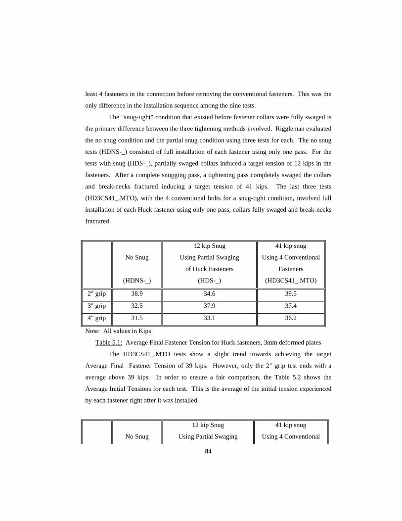
84
least 4 fasteners in the connection before removing the conventional fasteners. This was the
only difference in the installation sequence among the nine tests.
The "snug-tight" condition that existed before fastener collars were fully swaged is
the primary difference between the three tightening methods involved. Riggleman evaluated
the no snug condition and the partial snug condition using three tests for each. The no snug
tests (HDNS-_) consisted of full installation of each fastener using only one pass. For the
tests with snug (HDS-_), partially swaged collars induced a target tension of 12 kips in the
fasteners. After a complete snugging pass, a tightening pass completely swaged the collars
and break-necks fractured inducing a target tension of 41 kips. The last three tests
(HD3CS41_.MTO), with the 4 conventional bolts for a snug-tight condition, involved full
installation of each Huck fastener using only one pass, collars fully swaged and break-necks
fractured.
No Snug
(HDNS-_)
12 kip Snug
Using Partial Swaging
of Huck Fasteners
(HDS-_)
41 kip snug
Using 4 Conventional
Fasteners
(HD3CS41_.MTO)
2" grip 38.9 34.6 39.5
3" grip 32.5 37.9 37.4
4" grip 31.5 33.1 36.2
Note: All values in Kips
Table 5.1: Average Final Fastener Tension for Huck fasteners, 3mm deformed plates
The HD3CS41_.MTO tests show a slight trend towards achieving the target
Average Final Fastener Tension of 39 kips. However, only the 2" grip test ends with a
average above 39 kips. In order to ensure a fair comparison, the Table 5.2 shows the
Average Initial Tensions for each test. This is the average of the initial tension experienced
by each fastener right after it was installed.
No Snug
12 kip Snug
Using Partial Swaging
41 kip snug
Using 4 Conventional

85
(HDNS-_)
of Huck Fasteners
(HDS-_)
Fasteners
(HD3CS41_.MTO)
2" grip 39.2 36.4 40.1
3" grip 39.6 38.7 40.1
4" grip 42.5 41.0 41.5
Note: All values in Kips
Table 5.2: Average Initial Fastener Tension for Huck fasteners, 3mm deformed plates
These values indicate that regardless of the initial tension that each fastener had
upon installation, the grip thickness and the amount of snug prior to installation are
controlling factors in the Average Final Fastener Tensions. The method of using 4
conventional fasteners for "snug-tight" condition seems to provide higher Average Final
Tight Fastener Tensions. However, as stated earlier, this method is still not effective for the
3" and 4" grip tests.
5.3 6MM DEFORMED PLATES One Huck fastener test involved the use of 6mm deformed plates. Prior to fastener
installation, the 6mm gap existed between the bent interior plate and the flat exterior plate on
top. The method of fastener installation involved full swaging using only one pass. This test
used the 2" grip thickness. The intent was to evaluate the effect of the larger deformation on
a grip that seemed to be averaging fairly well with the other tightening methods.
5.3.1 SINGLE PASS INSTALLATION METHOD, NO SNUG This one test followed the middle to the outside tightening pattern, using 6mm
deformed plates, with a one pass complete installation without any snug. HD6NS--2.MTO
identifies this series of tests. The middle to outside tightening sequence is intended to follow
the requirement of progressing from the most rigid part of the connection to the outside
edges. Following the specified sequence as in Figure 4.4, all twelve fasteners joined the
plates in the connection.

86
5.3.1.1 TEST RESULTS Table 5.3 and Figures C.16 through C.20 show the results of this test. The Average
Final Fastener Tension was below 39 kips despite the 40.3 kip average for initial fastener
tension. Significant loss of tension occurred in the first two rows installed. Eleven of the
twelve fasteners installed fell below the 39 kip minimum for final fastener tension by the end
of the test. The lowest final fastener tension was that of fastener #7 at 22.4 kips.
5.3.2 PLATE DEFORMATION COMPARISON Four other 2" grip tests provide the basis for comparison of the HD6NS--2.MTO
test results. Riggleman performed three of these tests. The first test (HFNS-2) involved no
plate deformation and no snugging, simply a single full swage pass. The second test
(HDNS-2) used 3mm deformed plates and no snugging, also using only a full swage pass.
The third test (HDS-2) used partial swaging for an initial 12 kip snug pass followed by a full
swaging pass. The fourth test (HD3CS412) used only a full swage pass after 4 conventional
bolts provided an initial snug-tight condition. The four statistics for all five tests are
presented in Table 5.3.
Average Average Average Average Test #
Final Initial Tension Tension All Standard Standard Standard Standard
Fastener Fastener Loss in Loss in Middle Deviation Deviation Deviation Deviation
to Tension Tension 1st Two Last Two Outside Rows Rows Pattern Installed Installed
HFNS-2 38.4 0.8 38.4 0.7 0.4 (GAIN)
0.3 0.3 0.3
HDNS-2 38.9 1.6 39.2 1.7 0.5 0.7 0.0 0.2
HDS-2 34.6 full swage
1.5 36.4 full swage
1.7 2.7 0.6 1.2 0.3

87
HD3CS412 39.5 1.0 40.1 1.0 0.8 0.3 0.4 0.3
HD6NS--2 36.6 5.2 40.3 2.4 7.2 3.7 0.4 0.5
Note: All values in Kips
Table 5.3: Summary of all 2" Grip Huck Fastener Tests
Only the tightening method used in HD3CS412 meets the requirements of the Bolt
Specification. However, this method becomes less effective as the grip length increases, as
discussed in section 5.2.2. For the 2" grip, the single pass method begins to loose its
effectiveness for meeting the required 39 kip minimum tension as the gap increases. There
seems to be clear evidence that the snug-tight condition of the Bolt Specification is a critical
requirement for obtaining the final 39 kip minimum tension in fasteners.
6. CHAPTER 6
OVERALL SUMMARY AND CONLUSIONS
Four primary factors (the method of installation, the pattern of tightening, the
thickness and out-of-flat condition of the connected material, and the degree of “snug tight”
existing between the material before final tightening) provide a basis for an evaluation of the
installation characteristics of high strength fasteners. Table 6.1 through Table 6.6
summarize the results of all tests in the form of average initial and final tensions for the
snugging, tightening, and touch-up passes. The turn-of-nut and calibrated wrench methods
of installation represent the majority of tests.

88
For 3mm deformed plates, the turn-of-nut method of installation provided a more
consistent level of acceptable final fastener tension after the tightening pass. 9 tests used the
turn-of-nut method of installation with 3mm deformed plates. All tests averaged final
fastener tensions above 39 kips. The 9 tests using the calibrated wrench method of
installation averaged only 7 tests above 39 kips. The 3 alternative design fastener test had 1
of 3 tests that averaged above 39 kips.
For 6mm deformed plates, the calibrated wrench method of installation provided
consistently higher final fastener tensions after the tightening pass. The average of the 4
calibrated wrench tests was 32.3 kips compared to an average of 19.4 kips for the 3 turn-of-
nut tests. Both averages are after the tightening pass. The one alternative design test
averaged only 36.6 kips.
The three patterns of tightening were middle to outside, left to right, and outside to
middle. 6 tests of each pattern (3mm gap) provide a comparison of the three patterns. The
Middle to outside produces an almost 3 kip higher average final fastener tension after the
tightening pass. It should be noted that if only the 2” and 3” grip test results are considered,
there is only a difference of about 1 kip between the tightening patterns. However, when 4”
grip tests are compared, the middle to outside tightening pattern produced the higher final
fastener tensions.
The greater the thickness of the plates and the more the initial curvature of the
center plate, the lower the final average fastener tensions after the tightening pass. It is
noted that the calibrated wrench method of installation provides more dependable average
final fastener tensions for these cases.
A comparison of the data in Appendix A and Appendix B reveals two important
points. A turn of nut of 1/2 of a rotation moves the nut 0.053” for a 7/8” diameter bolt
(ignoring any elongation of the bolt). Almost all 3mm gap tests had gaps less than 0.05”
after the snugging pass. All tests had average final tight fastener tensions greater than 39
kips. The 6mm gap tests that resulted well below 39 kip averages had gaps greater than
0.05” after the snugging pass.
The second point is a suggestion on how to ensure the turn-of-nut method meets the
requirement of the code. For plate deformations creating gaps greater than 3mm the turn-of-
nut method should be checked after the tightening pass. A suggestion would be to check at

89
least the first few fasteners tightened (most likely to be loose) with a calibrated torque
wrench.
A 12 kip “snug tight” condition was used for 19 of the 29 tests. This proved fairly
satisfactory until plate deformations of 6mm were encountered. The turn-of-nut method of
installation, which relies heavily upon a snug tight condition, failed to meet the minimum of
39 kips final fastener tension. The calibrated wrench method a touch-up pass, as required in
the Bolt Specification, provided the most consistent final fastener tensions of at least 39 kips.
Install. Method
Average Initial Snug
Tension
Average Final Snug
Tension
Average
Initial “Tight” Tension
Average
Final “Tight” Tension
Average
Initial Touch-up Tension
Average
Final Touch-upTension
Turn-of-Nut 12 kip Snug
MTO
9.6
7.1
52.8
51.9
N/A
N/A
Turn-of-Nut 12 kip Snug
LTR
11.9
8.7
53.2
52.1
N/A
N/A
Turn-of-Nut 12 kip Snug
OTM
11.1
7.7
52.6
51.8
N/A
N/A

90
Calibrated Wrench
25 kip Snug MTO
24.3
22.6
41.4
40.9
42.6
42.3
Calibrated Wrench
12 kip Snug LTR
12.5
8.9
40.6
39.9
41.7
41.6
Calibrated Wrench
12 kip Snug OTM
11.6
8.6
41.4
40.9
N/A
N/A
Huck C50L 4 Bolt Snug
MTO
N/A
N/A
40.1
39.5
N/A
N/A
Note: All Values in Kips MTO = Middle to Outside Tightening Pattern LTR = Left to Right Tightening Pattern OTM = Outside to Middle Tightening Pattern
Table 6.1: Summary of fastener tensions - 2” grip, 3mm deformed plate tests
Install. Method
Average Initial Snug
Tension
Average Final Snug
Tension
Average
Initial “Tight” Tension
Average
Final “Tight” Tension
Average
Initial Touch-up Tension
Average
Final Touch-up Tension
Turn-of-Nut 12 kip Snug
MTO
12.8
5.7
55.8
54.2
N/A
N/A
Turn-of-Nut 12 kip Snug
LTR
11.7
4.1
56.6
55.0
N/A
N/A
Turn-of-Nut 12 kip Snug
OTM
11.6
4.7
54.4
53.2
N/A
N/A

91
Calibrated Wrench
25 kip Snug MTO
26.2
18.9
41.5
41.0
40.2
40.2
Calibrated Wrench
12 kip Snug LTR
11.3
4.1
43.7
41.7
43.2
43.2
Calibrated Wrench
12 kip Snug OTM
11.8
5.4
40.9
39.9
N/A
N/A
Huck C50L 4 Bolt Snug
MTO
N/A
N/A
40.1
37.4
N/A
N/A
Note: All Values in Kips MTO = Middle to Outside Tightening Pattern LTR = Left to Right Tightening Pattern OTM = Outside to Middle Tightening Pattern
Table 6.2: Summary of fastener tensions - 3” grip, 3mm deformed plate tests
Install. Method
Average Initial Snug
Tension
Average Final Snug
Tension
Average
Initial “Tight” Tension
Average
Final “Tight” Tension
Average
Initial Touch-up Tension
Average
Final Touch-upTension
Turn-of-Nut 12 kip Snug
MTO
13.5
5.1
53.1
50.0
N/A
N/A
Turn-of-Nut 12 kip Snug
LTR
11.6
4.0
48.9
42.1
N/A
N/A
Turn-of-Nut 12 kip Snug
OTM
11.7
4.4
46.2
39.5
N/A
N/A
Calibrated
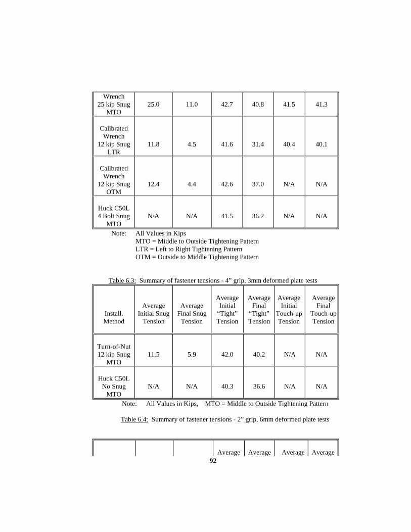
92
Wrench 25 kip Snug
MTO
25.0
11.0
42.7
40.8
41.5
41.3
Calibrated Wrench
12 kip Snug LTR
11.8
4.5
41.6
31.4
40.4
40.1
Calibrated Wrench
12 kip Snug OTM
12.4
4.4
42.6
37.0
N/A
N/A
Huck C50L 4 Bolt Snug
MTO
N/A
N/A
41.5
36.2
N/A
N/A
Note: All Values in Kips MTO = Middle to Outside Tightening Pattern LTR = Left to Right Tightening Pattern OTM = Outside to Middle Tightening Pattern
Table 6.3: Summary of fastener tensions - 4” grip, 3mm deformed plate tests
Install. Method
Average Initial Snug
Tension
Average Final Snug
Tension
Average
Initial “Tight” Tension
Average
Final “Tight” Tension
Average
Initial Touch-up Tension
Average
Final Touch-upTension
Turn-of-Nut 12 kip Snug
MTO
11.5
5.9
42.0
40.2
N/A
N/A
Huck C50L
No Snug MTO
N/A
N/A
40.3
36.6
N/A
N/A
Note: All Values in Kips, MTO = Middle to Outside Tightening Pattern
Table 6.4: Summary of fastener tensions - 2” grip, 6mm deformed plate tests
Average
Average
Average
Average

93
Install. Method
Average Initial Snug
Tension
Average Final Snug
Tension
Initial “Tight” Tension
Final “Tight” Tension
Initial Touch-up Tension
Final Touch-upTension
Turn-of-Nut 12 kip Snug
MTO
11.1
3.8
14.6
4.9
31.6
23.3
Calibrated Wrench
12 kip Snug MTO
11.0
3.4
42.1
29.0
42.7
42.0
Calibrated Wrench
25 kip Snug MTO
25.2
10.0
42.3
40.9
43.9
43.6
Note: All Values in Kips, MTO = Middle to Outside Tightening Pattern
Table 6.5: Summary of fastener tensions - 3” grip, 6mm deformed plate tests
Install. Method
Average Initial Snug
Tension
Average Final Snug
Tension
Average
Initial “Tight” Tension
Average
Final “Tight” Tension
Average
Initial Touch-up Tension
Average
Final Touch-upTension
Turn-of-Nut 25 kip Snug
then Code Snug
MTO
25.6
7.5
17.5
13.0
44.1
35.4
Calibrated Wrench
12 kip Snug MTO
12.1
4.5
42.4
23.0
39.9
38.9
Calibrated Wrench
25 kip Snug
25.2
7.6
42.4
36.4
42.2
41.9

94
MTO Note: All Values in Kips, MTO = Middle to Outside Tightening Pattern
Table 6.6: Summary of fastener tensions - 4” grip, 6mm deformed plate tests

95
APPENDIX A
GAP HISTORIES FOR ALL TESTS
INDEX OF FIGURES

96
A.1 Front gap between interior plate and top exterior plate
CD3TN123.MTO ......................................................................................... 104
A.2 Back gap between interior plate and top exterior plate
CD3TN123.MTO ......................................................................................... 104
A.3 Left side gap between interior plate and bottom exterior plate
CD3TN123.MTO ......................................................................................... 104
A.4 Right side gap between interior plate and bottom exterior plate
CD3TN123.MTO ......................................................................................... 104
A.5 Front gap between interior plate and top exterior plate
CD3TN124.MTO ......................................................................................... 105
A.6 Back gap between interior plate and top exterior plate
CD3TN124.MTO ......................................................................................... 105
A.7 Left side gap between interior plate and bottom exterior plate
CD3TN124.MTO ......................................................................................... 105
A.8 Right side gap between interior plate and bottom exterior plate
CD3TN124.MTO ......................................................................................... 105
A.9 Front gap between interior plate and top exterior plate
CD3TN122.LTR .......................................................................................... 106
A.10 Back gap between interior plate and top exterior plate
CD3TN122.LTR .......................................................................................... 106
A.11 Left side gap between interior plate and bottom exterior plate
CD3TN122.LTR .......................................................................................... 106
A.12 Right side gap between interior plate and bottom exterior plate
CD3TN122.LTR .......................................................................................... 106
A.13 Front gap between interior plate and top exterior plate
CD3TN123.LTR .......................................................................................... 107
A.14 Back gap between interior plate and top exterior plate
CD3TN123.LTR .......................................................................................... 107
A.15 Left side gap between interior plate and bottom exterior plate
CD3TN123.LTR .......................................................................................... 107

97
A.16 Right side gap between interior plate and bottom exterior plate
CD3TN123.LTR .......................................................................................... 107
A.17 Front gap between interior plate and top exterior plate
CD3TN124.LTR .......................................................................................... 108
A.18 Back gap between interior plate and top exterior plate
CD3TN124.LTR .......................................................................................... 108
A.19 Left side gap between interior plate and bottom exterior plate
CD3TN124.LTR .......................................................................................... 108
A.20 Right side gap between interior plate and bottom exterior plate
CD3TN124.LTR .......................................................................................... 108
A.21 Front gap between interior plate and top exterior plate
CD3TN122.OTM ......................................................................................... 109
A.22 Back gap between interior plate and top exterior plate
CD3TN122.OTM ......................................................................................... 109
A.23 Left side gap between interior plate and bottom exterior plate
CD3TN122.OTM ......................................................................................... 109
A.24 Right side gap between interior plate and bottom exterior plate
CD3TN122.OTM ......................................................................................... 109
A.25 Front gap between interior plate and top exterior plate
CD3TN123.OTM ......................................................................................... 110
A.26 Back gap between interior plate and top exterior plate
CD3TN123.OTM ......................................................................................... 110
A.27 Left side gap between interior plate and bottom exterior plate
CD3TN123.OTM ......................................................................................... 110
A.28 Right side gap between interior plate and bottom exterior plate
CD3TN123.OTM ......................................................................................... 110
A.29 Front gap between interior plate and top exterior plate
CD3TN124.OTM ......................................................................................... 111
A.30 Back gap between interior plate and top exterior plate
CD3TN124.OTM ......................................................................................... 111
A.31 Left side gap between interior plate and bottom exterior plate

98
CD3TN124.OTM ......................................................................................... 111
A.32 Right side gap between interior plate and bottom exterior plate
CD3TN124.OTM ......................................................................................... 111
A.33 Front gap between interior plate and top exterior plate
CD3CW252.MTO ....................................................................................... 112
A.34 Back gap between interior plate and top exterior plate
CD3CW252.MTO ....................................................................................... 112
A.35 Left side gap between interior plate and bottom exterior plate
CD3CW252.MTO ....................................................................................... 112
A.36 Right side gap between interior plate and bottom exterior plate
CD3CW252.MTO ....................................................................................... 112
A.37 Front gap between interior plate and top exterior plate
CD3CW253.MTO ....................................................................................... 113
A.38 Back gap between interior plate and top exterior plate
CD3CW253.MTO ....................................................................................... 113
A.39 Left side gap between interior plate and bottom exterior plate
CD3CW253.MTO ....................................................................................... 113
A.40 Right side gap between interior plate and bottom exterior plate
CD3CW253.MTO ....................................................................................... 113
A.41 Front gap between interior plate and top exterior plate
CD3CW254.MTO ....................................................................................... 114
A.42 Back gap between interior plate and top exterior plate
CD3CW254.MTO ....................................................................................... 114
A.43 Left side gap between interior plate and bottom exterior plate
CD3CW254.MTO ....................................................................................... 114
A.44 Right side gap between interior plate and bottom exterior plate
CD3CW254.MTO ....................................................................................... 114
A.45 Front gap between interior plate and top exterior plate
CD3CW122.LTR ......................................................................................... 115
A.46 Back gap between interior plate and top exterior plate
CD3CW122.LTR ......................................................................................... 115

99
A.47 Left side gap between interior plate and bottom exterior plate
CD3CW122.LTR ......................................................................................... 115
A.48 Right side gap between interior plate and bottom exterior plate
CD3CW122.LTR ......................................................................................... 115
A.49 Front gap between interior plate and top exterior plate
CD3CW123.LTR ......................................................................................... 116
A.50 Back gap between interior plate and top exterior plate
CD3CW123.LTR ......................................................................................... 116
A.51 Left side gap between interior plate and bottom exterior plate
CD3CW123.LTR ......................................................................................... 116
A.52 Right side gap between interior plate andbottom exterior plate
CD3CW123.LTR ......................................................................................... 116
A.53 Front gap between interior plate and top exterior plate
CD3CW124.LTR ......................................................................................... 117
A.54 Back gap between interior plate and top exterior plate
CD3CW124.LTR ......................................................................................... 117
A.54 Left side gap between interior plate and bottom exterior plate
CD3CW124.LTR ......................................................................................... 117
A.56 Right side gap between interior plate and bottom exterior plate
CD3CW124.LTR ......................................................................................... 117
A.57 Front gap between interior plate and top exterior plate
CD3CW122.OTM ....................................................................................... 118
A.58 Back gap between interior plate and top exterior plate
CD3CW122.OTM ....................................................................................... 118
A.59 Left side gap between interior plate and bottom exterior plate
CD3CW122.OTM ....................................................................................... 118
A.60 Right side gap between interior plate andbottom exterior plate
CD3CW122.OTM ....................................................................................... 118
A.61 Front gap between interior plate and top exterior plate
CD3CW123.OTM ....................................................................................... 119
A.62 Back gap between interior plate and top exterior plate

100
CD3CW123.OTM ....................................................................................... 119
A.63 Left side gap between interior plate and bottom exterior plate
CD3CW123.OTM ....................................................................................... 119
A.64 Right side gap between interior plate and bottom exterior plate
CD3CW123.OTM ....................................................................................... 119
A.65 Front gap between interior plate and top exterior plate
CD3CW124.OTM ....................................................................................... 120
A.66 Back gap between interior plate and top exterior plate
CD3CW124.OTM ....................................................................................... 120
A.67 Left side gap between interior plate and bottom exterior plate
CD3CW124.OTM ....................................................................................... 120
A.68 Right side gap between interior plate and bottom exterior plate
CD3CW124.OTM ....................................................................................... 120
A.69 Front gap between interior plate and top exterior plate
CD6TN122.MTO ......................................................................................... 121
A.70 Back gap between interior plate and top exterior plate
CD6TN122.MTO ......................................................................................... 121
A.71 Left side gap between interior plate and bottom exterior plate
CD6TN122.MTO ......................................................................................... 121
A.72 Right side gap between interior plate and bottom exterior plate
CD6TN122.MTO ......................................................................................... 121
A.73 Front gap between interior plate and top exterior plate
CD6TN123.MTO ......................................................................................... 122
A.74 Back gap between interior plate and top exterior plate
CD6TN123.MTO ......................................................................................... 122
A.75 Left side gap between interior plate and bottom exterior plate
CD6TN123.MTO ......................................................................................... 122
A.76 Right side gap between interior plate and bottom exterior plate
CD6TN123.MTO ......................................................................................... 122
A.77 Front gap between interior plate and top exterior plate
CD6TN254.MTO ......................................................................................... 123

101
A.78 Back gap between interior plate and top exterior plate
CD6TN254.MTO ......................................................................................... 123
A.79 Left side gap between interior plate and bottom exterior plate
CD6TN254.MTO ......................................................................................... 123
A.80 Right side gap between interior plate and bottom exterior plate
CD6TN254.MTO ......................................................................................... 123
A.81 Front gap between interior plate and top exterior plate
CD6CW123.MTO ....................................................................................... 124
A.82 Back gap between interior plate and top exterior plate
CD6CW123.MTO ....................................................................................... 124
A.83 Left side gap between interior plate and bottom exterior plate
CD6CW123.MTO ....................................................................................... 124
A.84 Right side gap between interior plate and bottom exterior plate
CD6CW123.MTO ....................................................................................... 124
A.85 Front gap between interior plate and top exterior plate
CD6CW124.MTO ....................................................................................... 125
A.86 Back gap between interior plate and top exterior plate
CD6CW124.MTO ....................................................................................... 125
A.87 Left side gap between interior plate and bottom exterior plate
CD6CW124.MTO ....................................................................................... 125
A.88 Right side gap between interior plate and bottom exterior plate
CD6CW124.MTO ....................................................................................... 125
A.89 Front gap between interior plate and top exterior plate
CD6CW253.MTO ....................................................................................... 126
A.90 Back gap between interior plate and top exterior plate
CD6CW253.MTO ....................................................................................... 126
A.91 Left side gap between interior plate and bottom exterior plate
CD6CW253.MTO ....................................................................................... 126
A.92 Right side gap between interior plate and bottom exterior plate
CD6CW253.MTO ....................................................................................... 126
A.93 Front gap between interior plate and top exterior plate

102
CD6CW254.MTO ....................................................................................... 127
A.94 Back gap between interior plate and top exterior plate
CD6CW254.MTO ....................................................................................... 127
A.95 Left side gap between interior plate and bottom exterior plate
CD6CW254.MTO ....................................................................................... 127
A.96 Right side gap between interior plate and bottom exterior plate
CD6CW254.MTO ....................................................................................... 127
A.97 Front gap between interior plate and top exterior plate
HD3CS412.MTO ......................................................................................... 128
A.98 Back gap between interior plate and top exterior plate
HD3CS412.MTO ......................................................................................... 128
A.99 Left side gap between interior plate and bottom exterior plate
HD3CS412.MTO ......................................................................................... 128
A.100 Right side gap between interior plate and bottom exterior plate
HD3CS412.MTO ......................................................................................... 128
A.101 Front gap between interior plate and top exterior plate
HD3CS413.MTO ......................................................................................... 129
A.102 Back gap between interior plate and top exterior plate
HD3CS413.MTO ......................................................................................... 129
A.103 Left side gap between interior plate and bottom exterior plate
HD3CS413.MTO ......................................................................................... 129
A.104 Right side gap between interior plate and bottom exterior plate
HD3CS413.MTO ......................................................................................... 129
A.105 Front gap between interior plate and top exterior plate
HD3CS414.MTO ......................................................................................... 130
A.106 Back gap between interior plate and top exterior plate
HD3CS414.MTO ......................................................................................... 130
A.107 Left side gap between interior plate and bottom exterior plate
HD3CS414.MTO ......................................................................................... 130
A.108 Right side gap between interior plate and bottom exterior plate
HD3CS414.MTO ......................................................................................... 130
103
A.109 Front gap between interior plate and top exterior plate
HD6NS--2.MTO .......................................................................................... 131
A.110 Back gap between interior plate and top exterior plate
HD6NS--2.MTO .......................................................................................... 131
A.111 Left side gap between interior plate and bottom exterior plate
HD6NS--2.MTO .......................................................................................... 131
A.112 Right side gap between interior plate and bottom exterior plate
HD6NS--2.MTO .......................................................................................... 131

Figure A.1: Front Gap Between Interior Plate and Top Exterior Plate CD3TN123.MTO
Figure A.2: Back Gap Between Interior Plate and Top Exterior Plate CD3TN123.MTO
Figure A.3: Left Side Gap Between Interior Plt. and Bottom Exterior Plt. CD3TN123.MTO
Figure A.4: Right Side Gap Between Interior Plt. and Bottom Exterior Plt. CD3TN123.MTO
.00
.02
.04
.06
.08
.10
.12
0 1 2 3 4 5 6 7 8 9 10 11 12
Tight
Snug
No Load
.00
.02
.04
.06
.08
.10
.12
0 1 2 3 4 5 6 7 8 9 10 11 12
Tight
Snug
No Load
.00
.02
.04
.06
.08
.10
.12
0 1 2 3 4 5 6 7 8 9 10 11 12
Tight
Snug
No Load
.00
.02
.04
.06
.08
.10
.12
0 1 2 3 4 5 6 7 8 9 10 11 12
Tight
Snug
No Load
Gap
, in
Location along Top Exterior Plate, in
Location along Top Exterior Plate, in
Location along Top Exterior Plate, in
Location along Top Exterior Plate, in
Gap
, in
Gap
, in
Gap
, in
104
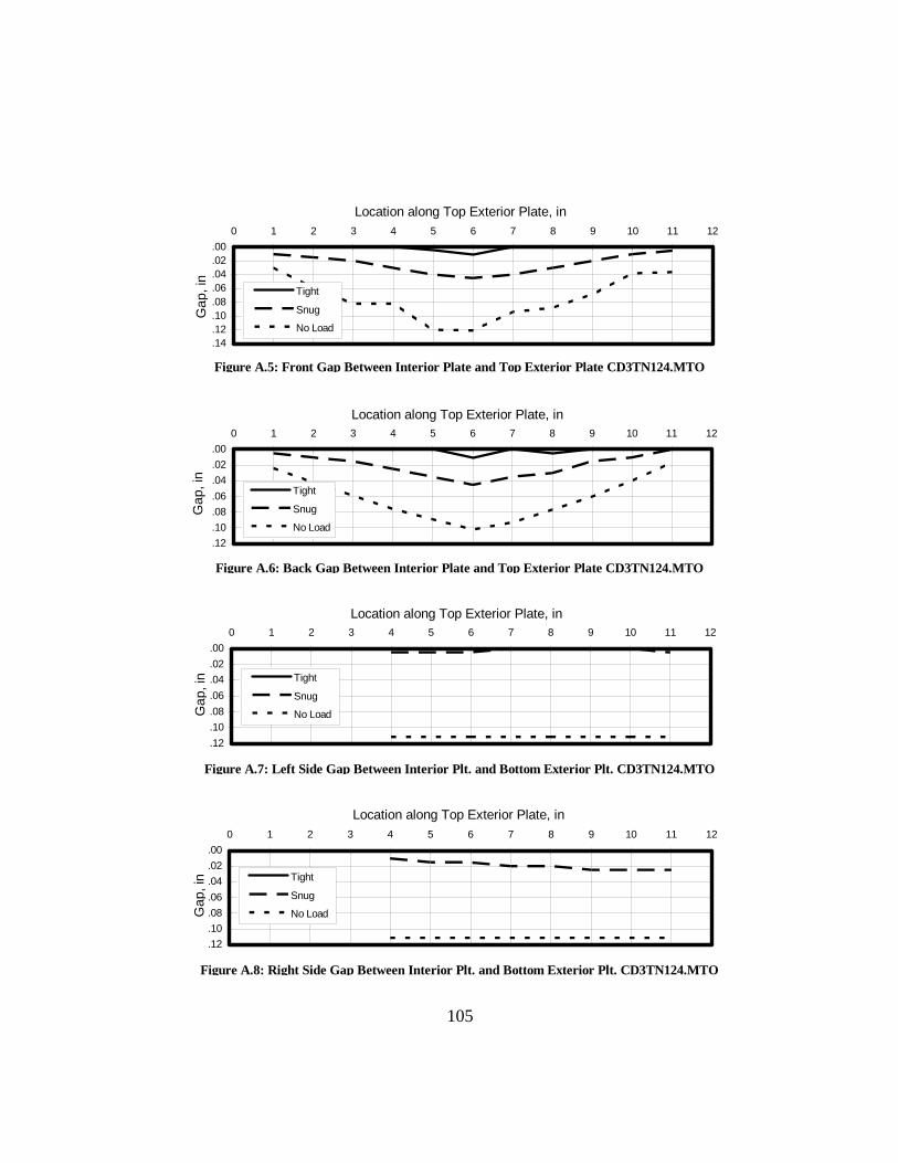
Figure A.5: Front Gap Between Interior Plate and Top Exterior Plate CD3TN124.MTO
Figure A.6: Back Gap Between Interior Plate and Top Exterior Plate CD3TN124.MTO
Figure A.7: Left Side Gap Between Interior Plt. and Bottom Exterior Plt. CD3TN124.MTO
Figure A.8: Right Side Gap Between Interior Plt. and Bottom Exterior Plt. CD3TN124.MTO
.00
.02
.04
.06
.08
.10
.12
.14
0 1 2 3 4 5 6 7 8 9 10 11 12
Tight
Snug
No Load
.00
.02
.04
.06
.08
.10
.12
0 1 2 3 4 5 6 7 8 9 10 11 12
Tight
Snug
No Load
.00
.02
.04
.06
.08
.10
.12
0 1 2 3 4 5 6 7 8 9 10 11 12
Tight
Snug
No Load
.00
.02
.04
.06
.08
.10
.12
0 1 2 3 4 5 6 7 8 9 10 11 12
Tight
Snug
No Load
Gap
, in
Location along Top Exterior Plate, in
Location along Top Exterior Plate, in
Location along Top Exterior Plate, in
Location along Top Exterior Plate, in
Gap
, in
Gap
, in
Ga p
, in
105
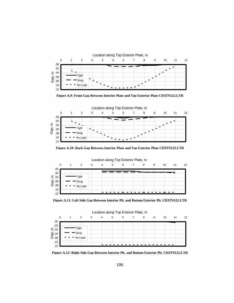
Figure A.9: Front Gap Between Interior Plate and Top Exterior Plate CD3TN122.LTR
Figure A.10: Back Gap Between Interior Plate and Top Exterior Plate CD3TN122.LTR
Figure A.11: Left Side Gap Between Interior Plt. and Bottom Exterior Plt. CD3TN122.LTR
Figure A.12: Right Side Gap Between Interior Plt. and Bottom Exterior Plt. CD3TN122.LTR
.00
.02
.04
.06
.08
.10
.12
0 1 2 3 4 5 6 7 8 9 10 11 12
Tight
Snug
No Load
.00
.02
.04
.06
.08
.10
.12
0 1 2 3 4 5 6 7 8 9 10 11 12
Tight
Snug
No Load
.00
.02
.04
.06
.08
.10
.12
0 1 2 3 4 5 6 7 8 9 10 11 12
Tight
Snug
No Load
.00
.02
.04
.06
.08
.10
.12
0 1 2 3 4 5 6 7 8 9 10 11 12
Tight
Snug
No Load
Gap
, in
Location along Top Exterior Plate, in
Location along Top Exterior Plate, in
Location along Top Exterior Plate, in
Location along Top Exterior Plate, in
Gap
, in
Gap
, in
Ga p
, in
106

Figure A.13: Front Gap Between Interior Plate and Top Exterior Plate CD3TN123.LTR
Figure A.14: Back Gap Between Interior Plate and Top Exterior Plate CD3TN123.LTR
Figure A.15: Left Side Gap Between Interior Plt. and Bottom Exterior Plt. CD3TN123.LTR
Figure A.16: Right Side Gap Between Interior Plt. and Bottom Exterior Plt. CD3TN123.LTR
.00
.02
.04
.06
.08
.10
.12
0 1 2 3 4 5 6 7 8 9 10 11 12
Tight
Snug
No Load
.00
.02
.04
.06
.08
.10
.12
.14
0 1 2 3 4 5 6 7 8 9 10 11 12
Tight
Snug
No Load
.00
.02
.04
.06
.08
.10
.12
0 1 2 3 4 5 6 7 8 9 10 11 12
Tight
Snug
No Load
.00
.02
.04
.06
.08
.10
.12
0 1 2 3 4 5 6 7 8 9 10 11 12
Tight
Snug
No Load
Gap
, in
Location along Top Exterior Plate, in
Location along Top Exterior Plate, in
Location along Top Exterior Plate, in
Location along Top Exterior Plate, in
Gap
, in
Gap
, in
Ga p
, in
107
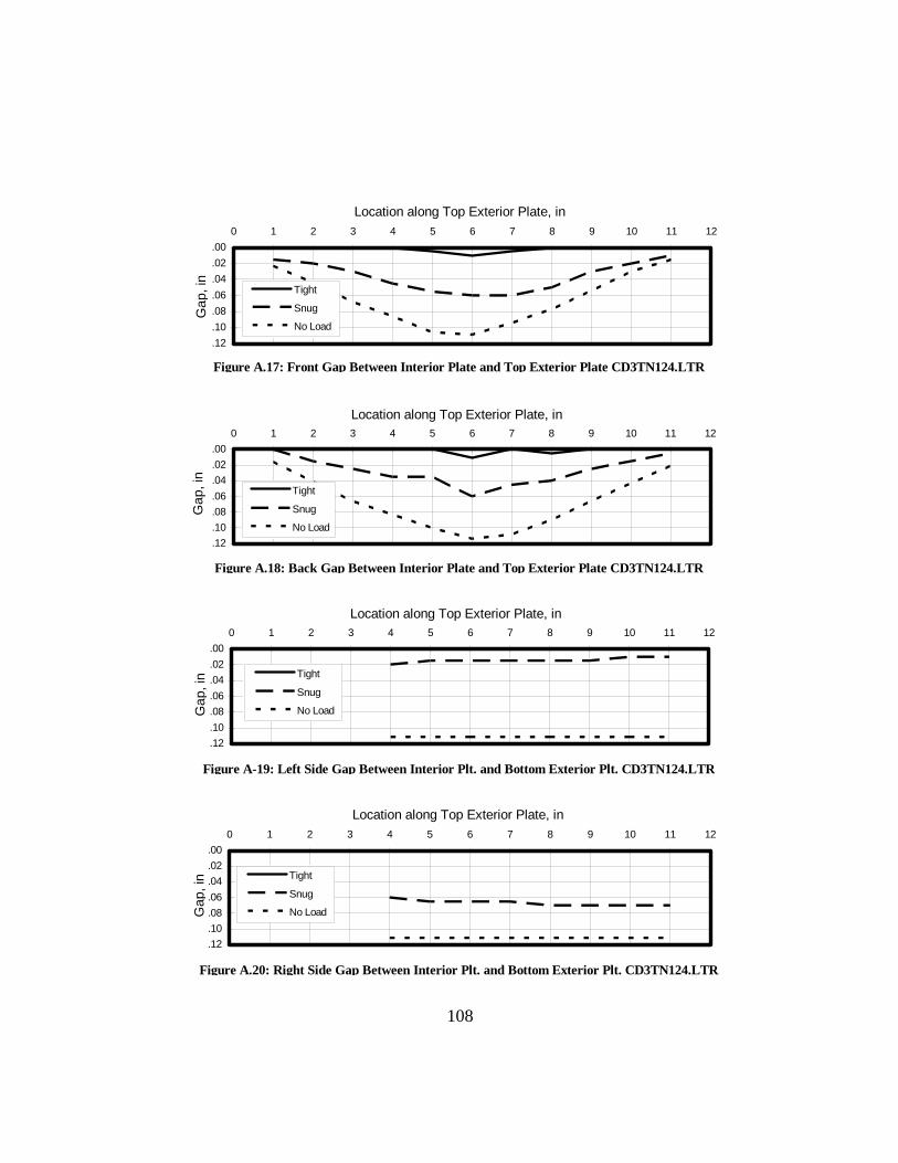
Figure A.17: Front Gap Between Interior Plate and Top Exterior Plate CD3TN124.LTR
Figure A.18: Back Gap Between Interior Plate and Top Exterior Plate CD3TN124.LTR
Figure A-19: Left Side Gap Between Interior Plt. and Bottom Exterior Plt. CD3TN124.LTR
Figure A.20: Right Side Gap Between Interior Plt. and Bottom Exterior Plt. CD3TN124.LTR
.00
.02
.04
.06
.08
.10
.12
0 1 2 3 4 5 6 7 8 9 10 11 12
Tight
Snug
No Load
.00
.02
.04
.06
.08
.10
.12
0 1 2 3 4 5 6 7 8 9 10 11 12
Tight
Snug
No Load
.00
.02
.04
.06
.08
.10
.12
0 1 2 3 4 5 6 7 8 9 10 11 12
Tight
Snug
No Load
.00
.02
.04
.06
.08
.10
.12
0 1 2 3 4 5 6 7 8 9 10 11 12
Tight
Snug
No Load
Gap
, in
Location along Top Exterior Plate, in
Location along Top Exterior Plate, in
Location along Top Exterior Plate, in
Location along Top Exterior Plate, in
Gap
, in
Gap
, in
Ga p
, in
108

Figure A.21: Front Gap Between Interior Plate and Top Exterior Plate CD3TN122.OTM
Figure A.22: Back Gap Between Interior Plate and Top Exterior Plate CD3TN122.OTM
Figure A.23: Left Side Gap Between Interior Plt. and Bottom Exterior Plt. CD3TN122.OTM
Figure A.24: Right Side Gap Between Interior Plt. and Bottom Exterior Plt. CD3TN122.OTM
.00
.02
.04
.06
.08
.10
.12
0 1 2 3 4 5 6 7 8 9 10 11 12
Tight
Snug
No Load
.00
.02
.04
.06
.08
.10
.12
0 1 2 3 4 5 6 7 8 9 10 11 12
Tight
Snug
No Load
.00
.02
.04
.06
.08
.10
.12
0 1 2 3 4 5 6 7 8 9 10 11 12
Tight
Snug
No Load
.00
.02
.04
.06
.08
.10
.12
0 1 2 3 4 5 6 7 8 9 10 11 12
Tight
Snug
No Load
Gap
, in
Location along Top Exterior Plate, in
Location along Top Exterior Plate, in
Location along Top Exterior Plate, in
Location along Top Exterior Plate, in
Gap
, in
Gap
, in
Ga p
, in
109

Figure A.25: Front Gap Between Interior Plate and Top Exterior Plate CD3TN123.OTM
Figure A.26: Back Gap Between Interior Plate and Top Exterior Plate CD3TN123.OTM
Figure A.27: Left Side Gap Between Interior Plt. and Bottom Exterior Plt. CD3TN123.OTM
Figure A.28: Right Side Gap Between Interior Plt. and Bottom Exterior Plt. CD3TN123.OTM
.00
.02
.04
.06
.08
.10
.12
0 1 2 3 4 5 6 7 8 9 10 11 12
Tight
Snug
No Load
.00
.02
.04
.06
.08
.10
.12
0 1 2 3 4 5 6 7 8 9 10 11 12
Tight
Snug
No Load
.00
.02
.04
.06
.08
.10
.12
0 1 2 3 4 5 6 7 8 9 10 11 12
Tight
Snug
No Load
.00
.02
.04
.06
.08
.10
.12
0 1 2 3 4 5 6 7 8 9 10 11 12
Tight
Snug
No Load
Gap
, in
Location along Top Exterior Plate, in
Location along Top Exterior Plate, in
Location along Top Exterior Plate, in
Location along Top Exterior Plate, in
Gap
, in
Gap
, in
Ga p
, in
110

Figure A.29: Front Gap Between Interior Plate and Top Exterior Plate CD3TN124.OTM
Figure A.30: Back Gap Between Interior Plate and Top Exterior Plate CD3TN124.OTM
Figure A.31: Left Side Gap Between Interior Plt. and Bottom Exterior Plt. CD3TN124.OTM
Figure A.32: Right Side Gap Between Interior Plt. and Bottom Exterior Plt. CD3TN124.OTM
.00
.02
.04
.06
.08
.10
.12
0 1 2 3 4 5 6 7 8 9 10 11 12
Tight
Snug
No Load
.00
.02
.04
.06
.08
.10
.12
0 1 2 3 4 5 6 7 8 9 10 11 12
Tight
Snug
No Load
.00
.02
.04
.06
.08
.10
.12
0 1 2 3 4 5 6 7 8 9 10 11 12
Tight
Snug
No Load
.00
.02
.04
.06
.08
.10
.12
0 1 2 3 4 5 6 7 8 9 10 11 12
Tight
Snug
No Load
Gap
, in
Location along Top Exterior Plate, in
Location along Top Exterior Plate, in
Location along Top Exterior Plate, in
Location along Top Exterior Plate, in
Gap
, in
Gap
, in
Ga p
, in
111

Figure A.33: Front Gap Between Interior Plate and Top Exterior Plate CD3CW252.MTO
Figure A.34: Back Gap Between Interior Plate and Top Exterior Plate CD3CW252.MTO
Figure A.35: Left Side Gap Between Interior Plt. and Bottom Exterior Plt. CD3CW252.MTO
Figure A.36: Right Side Gap Between Interior Plt. and Bottom Exterior Plt. CD3CW252.MTO
.00
.02
.04
.06
.08
.10
.12
0 1 2 3 4 5 6 7 8 9 10 11 12
Touch-upTightSnugNo Load
.00
.02
.04
.06
.08
.10
.12
0 1 2 3 4 5 6 7 8 9 10 11 12
Touch-upTightSnug No Load
.00
.02
.04
.06
.08
.10
.12
0 1 2 3 4 5 6 7 8 9 10 11 12
Touch-upTightSnug No Load
.00
.02
.04
.06
.08
.10
.12
0 1 2 3 4 5 6 7 8 9 10 11 12
Touch-upTightSnug No Load
Gap
, in
Location along Top Exterior Plate, in
Location along Top Exterior Plate, in
Location along Top Exterior Plate, in
Location along Top Exterior Plate, in
Gap
, in
Gap
, in
Ga p
, in
112

Figure A.37: Front Gap Between Interior Plate and Top Exterior Plate CD3CW253.MTO
Figure A.38: Back Gap Between Interior Plate and Top Exterior Plate CD3CW253.MTO
Figure A.39: Left Side Gap Between Interior Plt. and Bottom Exterior Plt. CD3CW253.MTO
Figure A.40: Right Side Gap Between Interior Plt. and Bottom Exterior Plt. CD3CW253.MTO
.00
.02
.04
.06
.08
.10
.12
0 1 2 3 4 5 6 7 8 9 10 11 12
Touch-upTightSnugNo Load
.00
.02
.04
.06
.08
.10
.12
.14
0 1 2 3 4 5 6 7 8 9 10 11 12
Touch-upTightSnug No Load
.00
.02
.04
.06
.08
.10
.12
.14
0 1 2 3 4 5 6 7 8 9 10 11 12
Touch-upTightSnug No Load
.00
.02
.04
.06
.08
.10
.12
.14
0 1 2 3 4 5 6 7 8 9 10 11 12
Touch-upTightSnug No Load
Gap
, in
Location along Top Exterior Plate, in
Location along Top Exterior Plate, in
Location along Top Exterior Plate, in
Location along Top Exterior Plate, in
Gap
, in
Gap
, in
Ga p
, in
113

Figure A.41: Front Gap Between Interior Plate and Top Exterior Plate CD3CW254.MTO
Figure A.42: Back Gap Between Interior Plate and Top Exterior Plate CD3CW254.MTO
Figure A.43: Left Side Gap Between Interior Plt. and Bottom Exterior Plt. CD3CW254.MTO
Figure A.44: Right Side Gap Between Interior Plt. and Bottom Exterior Plt. CD3CW254.MTO
.00
.02
.04
.06
.08
.10
.12
.14
0 1 2 3 4 5 6 7 8 9 10 11 12
Touch-upTightSnugNo Load
.00
.05
.10
.15
0 1 2 3 4 5 6 7 8 9 10 11 12
Touch-upTightSnug No Load
.00
.02
.04
.06
.08
.10
.12
.14
0 1 2 3 4 5 6 7 8 9 10 11 12
Touch-upTightSnug No Load
.00
.02
.04
.06
.08
.10
.12
.14
0 1 2 3 4 5 6 7 8 9 10 11 12
Touch-upTightSnug No Load
Gap
, in
Location along Top Exterior Plate, in
Location along Top Exterior Plate, in
Location along Top Exterior Plate, in
Location along Top Exterior Plate, in
Gap
, in
Gap
, in
Ga p
, in
114
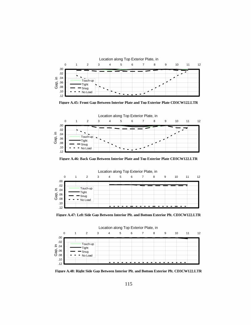
Figure A.45: Front Gap Between Interior Plate and Top Exterior Plate CD3CW122.LTR
Figure A.46: Back Gap Between Interior Plate and Top Exterior Plate CD3CW122.LTR
Figure A.47: Left Side Gap Between Interior Plt. and Bottom Exterior Plt. CD3CW122.LTR
Figure A.48: Right Side Gap Between Interior Plt. and Bottom Exterior Plt. CD3CW122.LTR
.00
.02
.04
.06
.08
.10
.12
0 1 2 3 4 5 6 7 8 9 10 11 12
Touch-upTightSnugNo Load
.00
.02
.04
.06
.08
.10
.12
0 1 2 3 4 5 6 7 8 9 10 11 12
Touch-upTightSnug No Load
.00
.02
.04
.06
.08
.10
.12
0 1 2 3 4 5 6 7 8 9 10 11 12
Touch-upTightSnug No Load
.00
.02
.04
.06
.08
.10
.12
0 1 2 3 4 5 6 7 8 9 10 11 12
Touch-upTightSnug No Load
Gap
, in
Location along Top Exterior Plate, in
Location along Top Exterior Plate, in
Location along Top Exterior Plate, in
Location along Top Exterior Plate, in
Gap
, in
Gap
, in
Ga p
, in
115
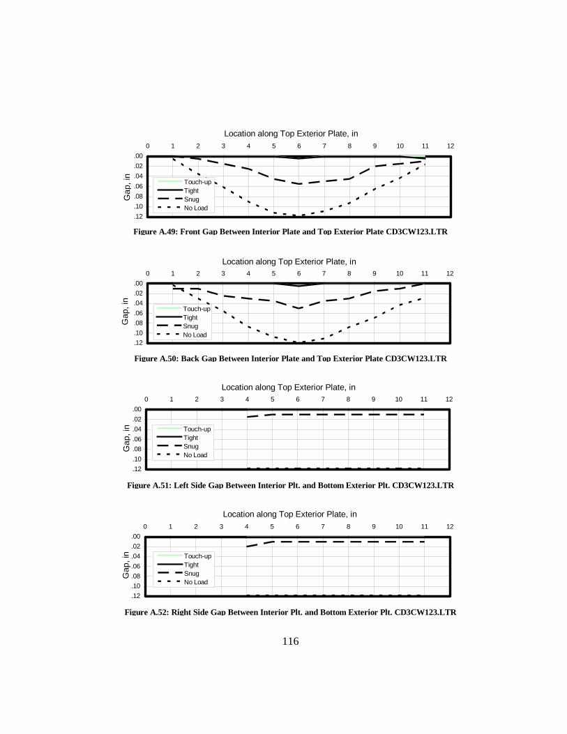
Figure A.49: Front Gap Between Interior Plate and Top Exterior Plate CD3CW123.LTR
Figure A.50: Back Gap Between Interior Plate and Top Exterior Plate CD3CW123.LTR
Figure A.51: Left Side Gap Between Interior Plt. and Bottom Exterior Plt. CD3CW123.LTR
Figure A.52: Right Side Gap Between Interior Plt. and Bottom Exterior Plt. CD3CW123.LTR
.00
.02
.04
.06
.08
.10
.12
0 1 2 3 4 5 6 7 8 9 10 11 12
Touch-upTightSnugNo Load
.00
.02
.04
.06
.08
.10
.12
0 1 2 3 4 5 6 7 8 9 10 11 12
Touch-upTightSnug No Load
.00
.02
.04
.06
.08
.10
.12
0 1 2 3 4 5 6 7 8 9 10 11 12
Touch-upTightSnug No Load
.00
.02
.04
.06
.08
.10
.12
0 1 2 3 4 5 6 7 8 9 10 11 12
Touch-upTightSnug No Load
Gap
, in
Location along Top Exterior Plate, in
Location along Top Exterior Plate, in
Location along Top Exterior Plate, in
Location along Top Exterior Plate, in
Gap
, in
Gap
, in
Ga p
, in
116

Figure A.53: Front Gap Between Interior Plate and Top Exterior Plate CD3CW124.LTR
Figure A.54: Back Gap Between Interior Plate and Top Exterior Plate CD3CW124.LTR
Figure A.55: Left Side Gap Between Interior Plt. and Bottom Exterior Plt. CD3CW124.LTR
Figure A.56: Right Side Gap Between Interior Plt. and Bottom Exterior Plt. CD3CW124.LTR
.00
.02
.04
.06
.08
.10
.12
0 1 2 3 4 5 6 7 8 9 10 11 12
Touch-upTightSnugNo Load
.00
.02
.04
.06
.08
.10
.12
.14
0 1 2 3 4 5 6 7 8 9 10 11 12
Touch-upTightSnug No Load
.00
.02
.04
.06
.08
.10
.12
0 1 2 3 4 5 6 7 8 9 10 11 12
Touch-upTightSnug No Load
.00
.02
.04
.06
.08
.10
.12
0 1 2 3 4 5 6 7 8 9 10 11 12
Touch-upTightSnug No Load
Gap
, in
Location along Top Exterior Plate, in
Location along Top Exterior Plate, in
Location along Top Exterior Plate, in
Location along Top Exterior Plate, in
Gap
, in
Gap
, in
Ga p
, in
117

Figure A.57: Front Gap Between Interior Plate and Top Exterior Plate CD3CW122.OTM
Figure A.58: Back Gap Between Interior Plate and Top Exterior Plate CD3CW122.OTM
Figure A.59: Left Side Gap Between Interior Plt. and Bottom Exterior Plt. CD3CW122.OTM
Figure A.60: Right Side Gap Between Interior Plt. and Bottom Exterior Plt. CD3CW122.OTM
.00
.02
.04
.06
.08
.10
.12
0 1 2 3 4 5 6 7 8 9 10 11 12
Touch-upTightSnugNo Load
.00
.02
.04
.06
.08
.10
.12
0 1 2 3 4 5 6 7 8 9 10 11 12
Touch-upTightSnug No Load
.00
.02
.04
.06
.08
.10
.12
0 1 2 3 4 5 6 7 8 9 10 11 12
Touch-upTightSnug No Load
.00
.02
.04
.06
.08
.10
.12
0 1 2 3 4 5 6 7 8 9 10 11 12
Touch-upTightSnug No Load
Gap
, in
Location along Top Exterior Plate, in
Location along Top Exterior Plate, in
Location along Top Exterior Plate, in
Location along Top Exterior Plate, in
Gap
, in
Gap
, in
Ga p
, in
118
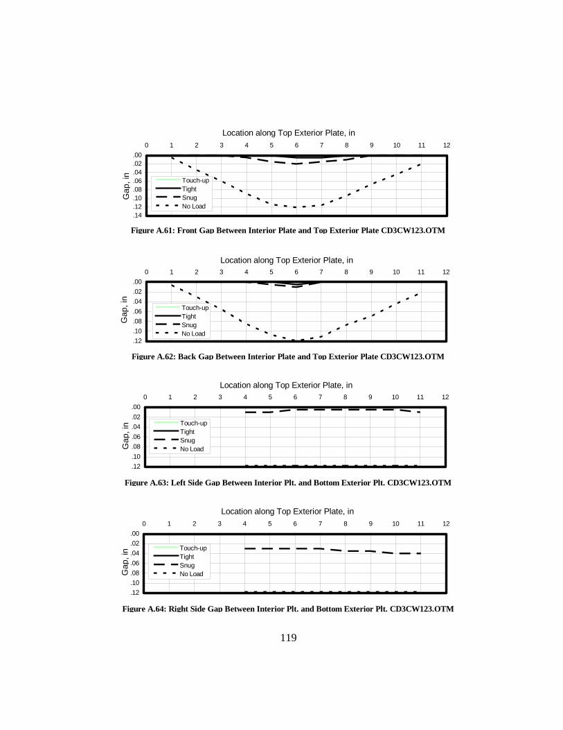
Figure A.61: Front Gap Between Interior Plate and Top Exterior Plate CD3CW123.OTM
Figure A.62: Back Gap Between Interior Plate and Top Exterior Plate CD3CW123.OTM
Figure A.63: Left Side Gap Between Interior Plt. and Bottom Exterior Plt. CD3CW123.OTM
Figure A.64: Right Side Gap Between Interior Plt. and Bottom Exterior Plt. CD3CW123.OTM
.00
.02
.04
.06
.08
.10
.12
.14
0 1 2 3 4 5 6 7 8 9 10 11 12
Touch-upTightSnugNo Load
.00
.02
.04
.06
.08
.10
.12
0 1 2 3 4 5 6 7 8 9 10 11 12
Touch-upTightSnug No Load
.00
.02
.04
.06
.08
.10
.12
0 1 2 3 4 5 6 7 8 9 10 11 12
Touch-upTightSnug No Load
.00
.02
.04
.06
.08
.10
.12
0 1 2 3 4 5 6 7 8 9 10 11 12
Touch-upTightSnug No Load
Gap
, in
Location along Top Exterior Plate, in
Location along Top Exterior Plate, in
Location along Top Exterior Plate, in
Location along Top Exterior Plate, in
Gap
, in
Gap
, in
Ga p
, in
119
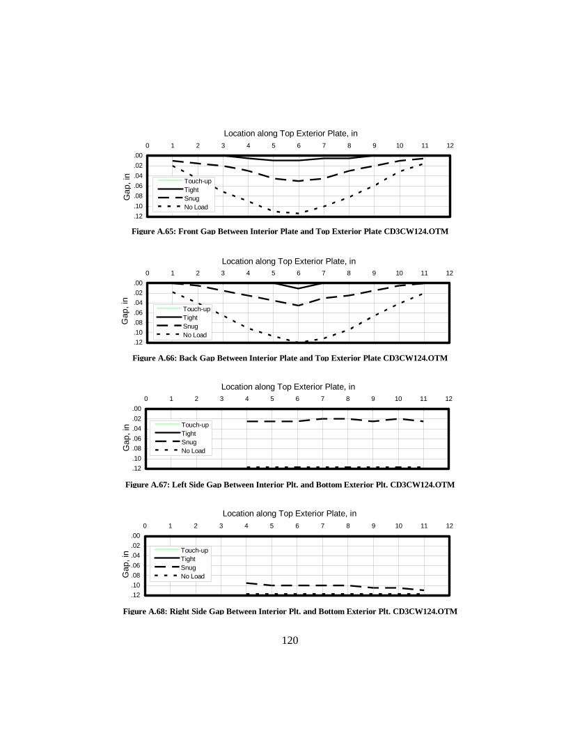
Figure A.65: Front Gap Between Interior Plate and Top Exterior Plate CD3CW124.OTM
Figure A.66: Back Gap Between Interior Plate and Top Exterior Plate CD3CW124.OTM
Figure A.67: Left Side Gap Between Interior Plt. and Bottom Exterior Plt. CD3CW124.OTM
Figure A.68: Right Side Gap Between Interior Plt. and Bottom Exterior Plt. CD3CW124.OTM
.00
.02
.04
.06
.08
.10
.12
0 1 2 3 4 5 6 7 8 9 10 11 12
Touch-upTightSnugNo Load
.00
.02
.04
.06
.08
.10
.12
0 1 2 3 4 5 6 7 8 9 10 11 12
Touch-upTightSnug No Load
.00
.02
.04
.06
.08
.10
.12
0 1 2 3 4 5 6 7 8 9 10 11 12
Touch-upTightSnug No Load
.00
.02
.04
.06
.08
.10
.12
0 1 2 3 4 5 6 7 8 9 10 11 12
Touch-upTightSnug No Load
Gap
, in
Location along Top Exterior Plate, in
Location along Top Exterior Plate, in
Location along Top Exterior Plate, in
Location along Top Exterior Plate, in
Gap
, in
Gap
, in
Gap
, in
120
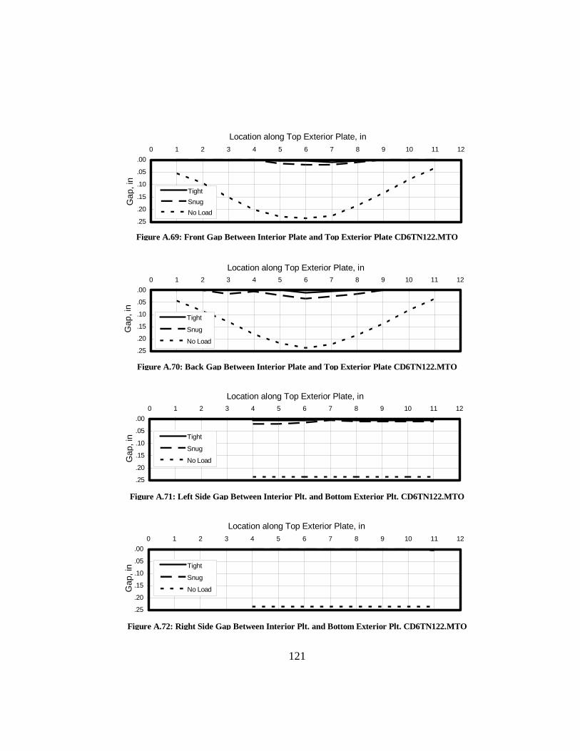
Figure A.69: Front Gap Between Interior Plate and Top Exterior Plate CD6TN122.MTO
Figure A.70: Back Gap Between Interior Plate and Top Exterior Plate CD6TN122.MTO
Figure A.71: Left Side Gap Between Interior Plt. and Bottom Exterior Plt. CD6TN122.MTO
Figure A.72: Right Side Gap Between Interior Plt. and Bottom Exterior Plt. CD6TN122.MTO
.00
.05
.10
.15
.20
.25
0 1 2 3 4 5 6 7 8 9 10 11 12
TightSnugNo Load
.00
.05
.10
.15
.20
.25
0 1 2 3 4 5 6 7 8 9 10 11 12
Tight
Snug
No Load
.00
.05
.10
.15
.20
.25
0 1 2 3 4 5 6 7 8 9 10 11 12
Tight
Snug
No Load
.00
.05
.10
.15
.20
.25
0 1 2 3 4 5 6 7 8 9 10 11 12
Tight
Snug
No Load
Gap
, in
Location along Top Exterior Plate, in
Location along Top Exterior Plate, in
Location along Top Exterior Plate, in
Location along Top Exterior Plate, in
Gap
, in
Gap
, in
Ga p
, in
121

Figure A.73: Front Gap Between Interior Plate and Top Exterior Plate CD6TN123.MTO
Figure A.74: Back Gap Between Interior Plate and Top Exterior Plate CD6TN123.MTO
Figure A.75: Left Side Gap Between Interior Plt. and Bottom Exterior Plt. CD6TN123.MTO
Figure A.76: Right Side Gap Between Interior Plt. and Bottom Exterior Plt. CD6TN123.MTO
.00
.05
.10
.15
.20
.25
0 1 2 3 4 5 6 7 8 9 10 11 12
2d 1/2 Turn1st 1/2 TurnSnugNo Load
.00
.05
.10
.15
.20
.25
0 1 2 3 4 5 6 7 8 9 10 11 12
2d 1/2 Turn1st 1/2 TurnSnug No Load
.00
.05
.10
.15
.20
.25
0 1 2 3 4 5 6 7 8 9 10 11 12
2d 1/2 Turn1st 1/2 TurnSnug No Load
.00
.05
.10
.15
.20
.25
0 1 2 3 4 5 6 7 8 9 10 11 12
2d 1/2 Turn1st 1/2 TurnSnug No Load
Gap
, in
Location along Top Exterior Plate, in
Location along Top Exterior Plate, in
Location along Top Exterior Plate, in
Location along Top Exterior Plate, in
Gap
, in
Gap
, in
Gap
, in
122

Figure A.77: Front Gap Between Interior Plate and Top Exterior Plate CD6TN254.MTO
Figure A.78: Back Gap Between Interior Plate and Top Exterior Plate CD6TN254.MTO
Figure A.79: Left Side Gap Between Interior Plt. and Bottom Exterior Plt. CD6TN254.MTO
Figure A.80: Right Side Gap Between Interior Plt. and Bottom Exterior Plt. CD6TN254.MTO
.00
.05
.10
.15
.20
.25
0 1 2 3 4 5 6 7 8 9 10 11 12
TightVisually Snug25 kip SnugNo Load
.00
.05
.10
.15
.20
.25
0 1 2 3 4 5 6 7 8 9 10 11 12
TightVisually Snug25 kip Snug No Load
.00
.05
.10
.15
.20
.25
0 1 2 3 4 5 6 7 8 9 10 11 12
TightVisually Snug25 kip Snug No Load
.00
.05
.10
.15
.20
.25
0 1 2 3 4 5 6 7 8 9 10 11 12
TightVisually Snug25 kip Snug No Load
Gap
, in
Location along Top Exterior Plate, in
Location along Top Exterior Plate, in
Location along Top Exterior Plate, in
Location along Top Exterior Plate, in
Gap
, in
Gap
, in
Ga p
, in
123

Figure A.81: Front Gap Between Interior Plate and Top Exterior Plate CD6CW123.MTO
Figure A.82: Back Gap Between Interior Plate and Top Exterior Plate CD6CW123.MTO
Figure A.83: Left Side Gap Between Interior Plt. and Bottom Exterior Plt. CD6CW123.MTO
Figure A.84: Right Side Gap Between Interior Plt. and Bottom Exterior Plt. CD6CW123.MTO
.00
.05
.10
.15
.20
.25
0 1 2 3 4 5 6 7 8 9 10 11 12
Touch-upTightSnugNo Load
.00
.05
.10
.15
.20
.25
0 1 2 3 4 5 6 7 8 9 10 11 12
Touch-upTightSnug No Load
.00
.05
.10
.15
.20
.25
0 1 2 3 4 5 6 7 8 9 10 11 12
Touch-upTightSnug No Load
.00
.05
.10
.15
.20
.25
0 1 2 3 4 5 6 7 8 9 10 11 12
Touch-upTightSnug No Load
Gap
, in
Location along Top Exterior Plate, in
Location along Top Exterior Plate, in
Location along Top Exterior Plate, in
Location along Top Exterior Plate, in
Gap
, in
Gap
, in
Gap
, in
124

Figure A.85: Front Gap Between Interior Plate and Top Exterior Plate CD6CW124.MTO
Figure A.86: Back Gap Between Interior Plate and Top Exterior Plate CD6CW124.MTO
FigureA.87: Left Side Gap Between Interior Plt. and Bottom Exterior Plt. CD6CW124.MTO
Figure A.88: Right Side Gap Between Interior Plt. and Bottom Exterior Plt. CD6CW124.MTO
.00
.05
.10
.15
.20
.25
0 1 2 3 4 5 6 7 8 9 10 11 12
Touch-upTightSnugNo Load
.00
.05
.10
.15
.20
.25
0 1 2 3 4 5 6 7 8 9 10 11 12
Touch-upTightSnug No Load
.00
.05
.10
.15
.20
.25
0 1 2 3 4 5 6 7 8 9 10 11 12
Touch-upTightSnug No Load
.00
.05
.10
.15
.20
.25
0 1 2 3 4 5 6 7 8 9 10 11 12
Touch-upTightSnug No Load
Gap
, in
Location along Top Exterior Plate, in
Location along Top Exterior Plate, in
Location along Top Exterior Plate, in
Location along Top Exterior Plate, in
Gap
, in
Gap
, in
Ga p
, in
125

Figure A.89: Front Gap Between Interior Plate and Top Exterior Plate CD6CW253.MTO
Figure A.90: Back Gap Between Interior Plate and Top Exterior Plate CD6CW253.MTO
Figure A.91: Left Side Gap Between Interior Plt. and Bottom Exterior Plt. CD6CW253.MTO
Figure A.92: Right Side Gap Between Interior Plt. and Bottom Exterior Plt. CD6CW253.MTO
.00
.05
.10
.15
.20
.25
0 1 2 3 4 5 6 7 8 9 10 11 12
Touch-upTightSnugNo Load
.00
.05
.10
.15
.20
.25
.30
0 1 2 3 4 5 6 7 8 9 10 11 12
Touch-upTightSnug No Load
.00
.05
.10
.15
.20
.25
0 1 2 3 4 5 6 7 8 9 10 11 12
Touch-upTightSnug No Load
.00
.05
.10
.15
.20
.25
0 1 2 3 4 5 6 7 8 9 10 11 12
Touch-upTightSnug No Load
Gap
, in
Location along Top Exterior Plate, in
Location along Top Exterior Plate, in
Location along Top Exterior Plate, in
Location along Top Exterior Plate, in
Gap
, in
Gap
, in
Gap
, in
126

Figure A.93: Front Gap Between Interior Plate and Top Exterior Plate CD6CW254.MTO
Figure A.94: Back Gap Between Interior Plate and Top Exterior Plate CD6CW254.MTO
Figure A.95: Left Side Gap Between Interior Plt. and Bottom Exterior Plt. CD6CW254.MTO
Figure A.96: Right Side Gap Between Interior Plt. and Bottom Exterior Plt. CD6CW254.MTO
.00
.05
.10
.15
.20
.25
0 1 2 3 4 5 6 7 8 9 10 11 12
Touch-upTightSnugNo Load
.00
.05
.10
.15
.20
.25
0 1 2 3 4 5 6 7 8 9 10 11 12
Touch-upTightSnug No Load
.00
.05
.10
.15
.20
.25
0 1 2 3 4 5 6 7 8 9 10 11 12
Touch-upTightSnug No Load
.00
.05
.10
.15
.20
.25
0 1 2 3 4 5 6 7 8 9 10 11 12
Touch-upTightSnug No Load
Gap
, in
Location along Top Exterior Plate, in
Location along Top Exterior Plate, in
Location along Top Exterior Plate, in
Location along Top Exterior Plate, in
Gap
, in
Gap
, in
Gap
, in
127

Figure A.97: Front Gap Between Interior Plate and Top Exterior Plate HD3CS412.MTO
Figure A.98: Back Gap Between Interior Plate and Top Exterior Plate HD3CS412.MTO
Figure A.99: Left Side Gap Between Interior Plt. and Bottom Exterior Plt. HD3CS412.MTO
Figure A.100: Right Side Gap Between Interior Plt. and Bottom Exterior Plt. HD3CS412.MTO
.00
.02
.04
.06
.08
.10
.12
0 1 2 3 4 5 6 7 8 9 10 11 12
TightSnugNo Load
.00
.02
.04
.06
.08
.10
.12
0 1 2 3 4 5 6 7 8 9 10 11 12
Tight
Snug
No Load
.00
.02
.04
.06
.08
.10
.12
0 1 2 3 4 5 6 7 8 9 10 11 12
Tight
Snug
No Load
.00
.02
.04
.06
.08
.10
.12
0 1 2 3 4 5 6 7 8 9 10 11 12
Tight
Snug
No Load
Gap
, in
Location along Top Exterior Plate, in
Location along Top Exterior Plate, in
Location along Top Exterior Plate, in
Location along Top Exterior Plate, in
Gap
, in
Gap
, in
Ga p
, in
128

Figure A.101: Front Gap Between Interior Plate and Top Exterior Plate HD3CS413.MTO
Figure A.102: Back Gap Between Interior Plate and Top Exterior Plate HD3CS413.MTO
Figure A.103: Left Side Gap Between Interior Plt. and Bottom Exterior Plt. HD3CS413.MTO
Figure A.104: Right Side Gap Between Interior Plt. and Bottom Exterior Plt. HD3CS413.MTO
.00
.02
.04
.06
.08
.10
.12
.14
0 1 2 3 4 5 6 7 8 9 10 11 12
TightSnugNo Load
.00
.02
.04
.06
.08
.10
.12
0 1 2 3 4 5 6 7 8 9 10 11 12
Tight
Snug
No Load
.00
.02
.04
.06
.08
.10
.12
.14
0 1 2 3 4 5 6 7 8 9 10 11 12
Tight
Snug
No Load
.00
.02
.04
.06
.08
.10
.12
.14
0 1 2 3 4 5 6 7 8 9 10 11 12
Tight
Snug
No Load
Gap
, in
Location along Top Exterior Plate, in
Location along Top Exterior Plate, in
Location along Top Exterior Plate, in
Location along Top Exterior Plate, in
Gap
, in
Gap
, in
Gap
, in
129

Figure A.105: Front Gap Between Interior Plate and Top Exterior Plate HD3CS414.MTO
Figure A.106: Back Gap Between Interior Plate and Top Exterior Plate HD3CS414.MTO
Figure A.107: Left Side Gap Between Interior Plt. and Bottom Exterior Plt. HD3CS414.MTO
Figure A.108: Right Side Gap Between Interior Plt. and Bottom Exterior Plt. HD3CS414.MTO
.00
.02
.04
.06
.08
.10
.12
0 1 2 3 4 5 6 7 8 9 10 11 12
TightSnugNo Load
.00
.02
.04
.06
.08
.10
.12
0 1 2 3 4 5 6 7 8 9 10 11 12
Tight
Snug
No Load
.00
.02
.04
.06
.08
.10
.12
0 1 2 3 4 5 6 7 8 9 10 11 12
Tight
Snug
No Load
.00
.02
.04
.06
.08
.10
.12
0 1 2 3 4 5 6 7 8 9 10 11 12
Tight
Snug
No Load
Gap
, in
Location along Top Exterior Plate, in
Location along Top Exterior Plate, in
Location along Top Exterior Plate, in
Location along Top Exterior Plate, in
Gap
, in
Gap
, in
Ga p
, in
130

131
Figure A.109: Front Gap Between Interior Plate and Top Exterior Plate HD6NS--2.MTO
FigureA.110: Back Gap Between Interior Plate and Top Exterior Plate HD6NS--2.MTO
Figure A.111: Left Side Gap Between Interior Plt. and Bottom Exterior Plt. HD6NS--2.MTO
Figure A.112: Right Side Gap Between Interior Plt. and Bottom Exterior Plt. HD6NS--2.MTO
.00
.05
.10
.15
.20
.25
0 1 2 3 4 5 6 7 8 9 10 11 12
Tight
No Load
.00
.05
.10
.15
.20
.25
0 1 2 3 4 5 6 7 8 9 10 11 12
Tight
No Load
.00
.05
.10
.15
.20
.25
0 1 2 3 4 5 6 7 8 9 10 11 12
Tight
No Load
.00
.05
.10
.15
.20
.25
0 1 2 3 4 5 6 7 8 9 10 11 12
Tight
No Load
Gap
, in
Location along Top Exterior Plate, in
Location along Top Exterior Plate, in
Location along Top Exterior Plate, in
Location along Top Exterior Plate, in
Gap
, in
Gap
, in
Gap
, in

132
APPENDIX B
RESULTS OF CONNECTION TESTS
WITH CONVENTIONAL FASTENERS

133
INDEX OF FIGURES
B-1 Fastener Tensions for Test CD3TN122.MTO .................................................. 138
B-2 Final Installed Tensions for Test CD3TN122.MTO ......................................... 139
B-3 Tensile Load History for Fastener # 4 - Test CD3TN122.MTO ..................... 139
B-4 Tensile Load History for Fastener # 8 - Test CD3TN122.MTO ..................... 140
B-5 Tensile Load History for Fastener # 2 - Test CD3TN122.MTO ...................... 140 B-6 Fastener Tensions for Test CD3TN123.MTO .................................................. 141
B-7 Final Installed Tensions for Test CD3TN123.MTO ......................................... 142
B-8 Tensile Load History for Fastener # 4 - Test CD3TN123.MTO ...................... 142
B-9 Tensile Load History for Fastener # 8 - Test CD3TN123.MTO ..................... 143
B-10 Tensile Load History for Fastener # 2 - Test CD3TN123.MTO ...................... 143 B-11 Fastener Tensions for Test CD3TN124.MTO .................................................. 144
B-12 Final Installed Tensions for Test CD3TN124.MTO ......................................... 145
B-13 Tensile Load History for Fastener # 4 - Test CD3TN124.MTO ..................... 145
B-14 Tensile Load History for Fastener # 8 - Test CD3TN124.MTO ..................... 146
B-15 Tensile Load History for Fastener # 2 - Test CD3TN124.MTO ...................... 146 B-16 Fastener Tensions for Test CD3TN122.LTR ................................................... 147
B-17 Final Installed Tensions for Test CD3TN122. LTR ......................................... 148
B-18 Tensile Load History for Fastener # 1 - Test CD3TN122. LTR ..................... 148
B-19 Tensile Load History for Fastener # 5 - Test CD3TN122. LTR ..................... 149
B-20 Tensile Load History for Fastener # 7 - Test CD3TN122. LTR ...................... 149 B-21 Fastener Tensions for Test CD3TN123. LTR .................................................. 150
B-22 Final Installed Tensions for Test CD3TN123. LTR ......................................... 151
B-23 Tensile Load History for Fastener # 1 - Test CD3TN123. LTR ...................... 151
B-24 Tensile Load History for Fastener # 5 - Test CD3TN123. LTR ...................... 152
B-25 Tensile Load History for Fastener # 7 - Test CD3TN123. LTR ...................... 152 B-26 Fastener Tensions for Test CD3TN124. LTR .................................................. 153
B-27 Final Installed Tensions for Test CD3TN124. LTR ......................................... 154
B-28 Tensile Load History for Fastener # 1 - Test CD3TN124. LTR ..................... 154

134
B-29 Tensile Load History for Fastener # 5 - Test CD3TN124. LTR ..................... 155
B-30 Tensile Load History for Fastener # 7 - Test CD3TN124. LTR ...................... 155 B-31 Fastener Tensions for Test CD3TN122.OTM .................................................. 156
B-32 Final Installed Tensions for Test CD3TN122.OTM ......................................... 157
B-33 Tensile Load History for Fastener # 1 - Test CD3TN122.OTM ...................... 157
B-34 Tensile Load History for Fastener # 10 - Test CD3TN122.OTM .................... 158
B-35 Tensile Load History for Fastener # 5 - Test CD3TN122.OTM ...................... 158 B-36 Fastener Tensions for Test CD3TN123.OTM .................................................. 159
B-37 Final Installed Tensions for Test CD3TN123.OTM ......................................... 160
B-38 Tensile Load History for Fastener # 1 - Test CD3TN123.OTM ...................... 160
B-39 Tensile Load History for Fastener # 10 - Test CD3TN123.OTM .................... 161
B-40 Tensile Load History for Fastener # 5 - Test CD3TN123.OTM ...................... 161 B-41 Fastener Tensions for Test CD3TN124.OTM .................................................. 162
B-42 Final Installed Tensions for Test CD3TN124.OTM ......................................... 163
B-43 Tensile Load History for Fastener # 1 - Test CD3TN124.OTM ...................... 163
B-44 Tensile Load History for Fastener # 10 - Test CD3TN124.OTM .................... 164
B-45 Tensile Load History for Fastener # 5 - Test CD3TN124.OTM ...................... 164 B-46 Fastener Tensions for Test CD3CW252.MTO ................................................. 165
B-47 Final Installed Tensions for Test CD3CW252.MTO ....................................... 166
B-48 Tensile Load History for Fastener # 4 - Test CD3CW252.MTO ..................... 166
B-49 Tensile Load History for Fastener # 8 - Test CD3CW252.MTO ..................... 167
B-50 Tensile Load History for Fastener # 2 - Test CD3CW252.MTO ..................... 167 B-51 Fastener Tensions for Test CD3CW253.MTO ................................................. 168
B-52 Final Installed Tensions for Test CD3CW253.MTO ....................................... 169
B-53 Tensile Load History for Fastener # 4 - Test CD3CW253.MTO ..................... 169
B-54 Tensile Load History for Fastener # 8 - Test CD3CW253.MTO ..................... 170
B-55 Tensile Load History for Fastener # 2 - Test CD3CW253.MTO ..................... 170 B-56 Fastener Tensions for Test CD3CW254.MTO ................................................. 171
B-57 Final Installed Tensions for Test CD3CW254.MTO ....................................... 172
B-58 Tensile Load History for Fastener # 4 - Test CD3CW254.MTO ..................... 172
B-59 Tensile Load History for Fastener # 8 - Test CD3CW254.MTO ..................... 173

135
B-60 Tensile Load History for Fastener # 2 - Test CD3CW254.MTO ..................... 173 B-61 Fastener Tensions for Test CD3CW122.LTR .................................................. 174
B-62 Final Installed Tensions for Test CD3CW122. LTR ........................................ 175
B-63 Tensile Load History for Fastener # 1 - Test CD3CW122. LTR .................... 175
B-64 Tensile Load History for Fastener # 5 - Test CD3CW122. LTR .................... 176
B-65 Tensile Load History for Fastener # 7 - Test CD3CW122. LTR ..................... 176 B-66 Fastener Tensions for Test CD3CW123. LTR ................................................. 177
B-67 Final Installed Tensions for Test CD3CW123. LTR ........................................ 178
B-68 Tensile Load History for Fastener # 1 - Test CD3CW123. LTR ..................... 178
B-69 Tensile Load History for Fastener # 5 - Test CD3CW123. LTR ..................... 179
B-70 Tensile Load History for Fastener # 7 - Test CD3CW123. LTR ..................... 179 B-71 Fastener Tensions for Test CD3CW124. LTR ................................................. 180
B-72 Final Installed Tensions for Test CD3CW124. LTR ........................................ 181
B-73 Tensile Load History for Fastener # 1 - Test CD3CW124. LTR .................... 181
B-74 Tensile Load History for Fastener # 5 - Test CD3CW124. LTR .................... 182
B-75 Tensile Load History for Fastener # 7 - Test CD3CW124. LTR ..................... 182 B-76 Fastener Tensions for Test CD3CW122.OTM ................................................. 183
B-77 Final Installed Tensions for Test CD3CW122.OTM ....................................... 184
B-78 Tensile Load History for Fastener # 1 - Test CD3CW122.OTM ..................... 184
B-79 Tensile Load History for Fastener # 10 - Test CD3CW122.OTM ................... 185
B-80 Tensile Load History for Fastener # 5 - Test CD3CW122.OTM ..................... 185 B-81 Fastener Tensions for Test CD3CW123.OTM ................................................. 186
B-82 Final Installed Tensions for Test CD3CW123.OTM ....................................... 187
B-83 Tensile Load History for Fastener # 1 - Test CD3CW123.OTM ..................... 187
B-84 Tensile Load History for Fastener # 10 - Test CD3CW123.OTM ................... 188
B-85 Tensile Load History for Fastener # 5 - Test CD3CW123.OTM ..................... 188 B-86 Fastener Tensions for Test CD3CW124.OTM ................................................. 189
B-87 Final Installed Tensions for Test CD3CW124.OTM ....................................... 190
B-88 Tensile Load History for Fastener # 1 - Test CD3CW124.OTM ..................... 190
B-89 Tensile Load History for Fastener # 10 - Test CD3CW124.OTM ................... 191
B-90 Tensile Load History for Fastener # 5 - Test CD3CW124.OTM ..................... 191

136
B-91 Fastener Tensions for Test CD6TN122.MTO .................................................. 192
B-92 Final Installed Tensions for Test CD6TN122.MTO ......................................... 193
B-93 Tensile Load History for Fastener # 4 - Test CD6TN122.MTO ..................... 193
B-94 Tensile Load History for Fastener # 8 - Test CD6TN122.MTO ..................... 194
B-95 Tensile Load History for Fastener # 2 - Test CD6TN122.MTO ...................... 194 B-96 Fastener Tensions for Test CD6TN123.MTO .................................................. 195
B-97 Final Installed Tensions for Test CD6TN123.MTO ......................................... 196
B-98 Tensile Load History for Fastener # 4 - Test CD6TN123.MTO ...................... 196
B-99 Tensile Load History for Fastener # 8 - Test CD6TN123.MTO ..................... 197
B-100 Tensile Load History for Fastener # 2 - Test CD6TN123.MTO ...................... 197 B-101 Fastener Tensions for Test CD6TN254.MTO .................................................. 198
B-102 Final Installed Tensions for Test CD6TN254.MTO ......................................... 199
B-103 Tensile Load History for Fastener # 4 - Test CD6TN254.MTO ..................... 199
B-104 Tensile Load History for Fastener # 8 - Test CD6TN254.MTO ..................... 200
B-105 Tensile Load History for Fastener # 2 - Test CD6TN254.MTO ...................... 200
B-106 Fastener Tensions for Test CD6CW123.MTO ................................................. 201
B-107 Final Installed Tensions for Test CD6CW123.MTO ....................................... 202
B-108 Tensile Load History for Fastener # 4 - Test CD6CW123.MTO ..................... 202
B-109 Tensile Load History for Fastener # 8 - Test CD6CW123.MTO ..................... 203
B-110 Tensile Load History for Fastener # 2 - Test CD6CW123.MTO ..................... 203 B-111 Fastener Tensions for Test CD6CW124.MTO ................................................. 204
B-112 Final Installed Tensions for Test CD6CW124.MTO ....................................... 205
B-113 Tensile Load History for Fastener # 4 - Test CD6CW124.MTO ..................... 205
B-114 Tensile Load History for Fastener # 8 - Test CD6CW124.MTO ..................... 206
B-115 Tensile Load History for Fastener # 2 - Test CD6CW124.MTO ..................... 206 B-116 Fastener Tensions for Test CD6CW253.MTO ................................................. 207
B-117 Final Installed Tensions for Test CD6CW253.MTO ....................................... 208
B-118 Tensile Load History for Fastener # 4 - Test CD6CW253.MTO ..................... 208
B-119 Tensile Load History for Fastener # 8 - Test CD6CW253.MTO ..................... 209
B-120 Tensile Load History for Fastener # 2 - Test CD6CW253.MTO ..................... 209 B-121 Fastener Tensions for Test CD6CW254.MTO ................................................. 210

137
B-122 Final Installed Tensions for Test CD6CW254.MTO ....................................... 211
B-123 Tensile Load History for Fastener # 4 - Test CD6CW254.MTO ..................... 211
B-124 Tensile Load History for Fastener # 8 - Test CD6CW254.MTO ..................... 212
B-125 Tensile Load History for Fastener # 2 - Test CD6CW254.MTO ..................... 212
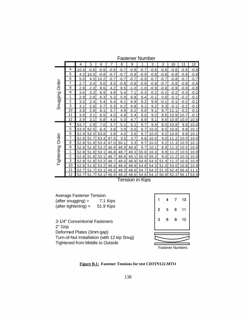
138
Fastener Number4 5 6 7 8 9 1 2 3 10 11 12
4 10.4 -0.6 -0.6 -0.6 -0.7 -0.8 -0.7 -0.6 -0.6 -0.6 -0.5 -0.65 4.3 10.0 -0.8 -0.7 -0.7 -0.9 -0.9 -0.8 -0.8 -0.8 -0.8 -0.86 5.0 4.5 10.2 -0.7 -0.7 -0.7 -0.9 -0.7 -0.7 -0.8 -0.7 -0.77 2.7 3.4 9.6 8.5 -0.8 -0.8 -0.9 -0.8 -0.7 -0.8 -0.8 -0.88 2.8 2.3 8.6 4.2 8.5 -1.0 -1.0 -0.9 -0.8 -0.9 -0.9 -0.89 3.6 3.2 6.9 4.8 5.4 7.1 -0.3 -0.2 -0.2 -0.2 -0.3 -0.21 2.9 2.6 6.3 5.3 5.9 6.8 9.4 -0.1 0.0 -0.1 -0.2 -0.12 3.2 2.4 5.4 5.4 6.1 6.9 9.2 9.9 -0.1 -0.1 -0.2 -0.13 3.1 2.6 5.7 5.3 6.2 6.8 9.1 9.2 9.3 -0.1 -0.2 -0.110 3.9 2.9 6.1 3.7 4.9 6.2 9.0 9.1 8.7 11.1 -0.2 -0.111 3.9 3.1 6.5 4.0 4.8 5.4 9.0 9.2 8.6 10.9 10.7 -0.112 3.9 3.1 6.8 4.0 5.0 4.7 8.9 9.1 8.6 10.8 10.0 10.54 53.7 2.9 7.0 3.7 5.1 5.1 9.7 9.4 8.5 10.8 9.8 10.05 53.0 52.5 6.4 3.8 3.9 5.0 9.7 10.0 8.5 10.8 9.8 10.16 52.9 52.0 53.8 3.8 4.0 3.6 9.7 10.0 9.2 10.8 9.8 10.17 52.8 51.7 53.3 47.5 3.5 3.7 9.6 10.0 9.0 11.2 10.0 10.08 52.8 51.8 53.4 47.0 50.1 3.3 9.7 10.0 9.2 11.3 10.5 10.19 52.8 51.8 53.2 46.9 48.9 49.9 9.7 10.1 8.9 11.3 10.5 10.91 52.8 51.8 53.1 46.8 48.7 49.3 55.6 10.3 8.9 11.2 10.5 10.92 52.8 51.8 53.1 46.7 48.6 49.1 55.0 55.2 9.0 11.2 10.5 10.93 52.8 51.8 53.2 46.7 48.5 48.9 54.9 54.5 51.4 11.2 10.5 10.910 52.8 51.8 53.2 46.6 48.4 48.8 54.8 54.3 51.0 53.0 10.8 10.911 52.7 51.7 53.1 46.5 48.3 48.6 54.7 54.2 51.0 52.4 56.4 11.112 52.7 51.7 53.1 46.5 48.2 48.6 54.6 54.1 50.9 52.2 56.1 53.9
Tension in Kips
Average Fastener Tension (after snugging) = 7.1 Kips(after tightening) = 51.9 Kips
3-1/4" Conventional Fasteners2" GripDeformed Plates (3mm gap)Turn-of-Nut Installation (with 12 kip Snug)Tightened from Middle to Outside
Fastener Numbers
Snu
ggin
g O
rder
Tigh
teni
ng O
rder
Figure B.1: Fastener Tensions for test CD3TN122.MTO

139
0
10
20
30
40
50
60
4 5 6 7 8 9 1 2 3 10 11 12Fastener Number
Fina
l Ins
talle
d Te
nsio
n (K
ips)
39 Kips
Figure B.2: Final Installed Tensions for Test CD3TN122.MTO
0
10
20
30
40
50
60
4 5 6 7 8 9 1 2 3 10 11 1Installed Fastener Number
Tens
ile L
oad
(Kip
s)
2
Snug
Tight
39 Kip Min.
Figure B.3: Tensile Load History for Fastener #4 - Test CD3TN122.MTO

140
0
10
20
30
40
50
60
4 5 6 7 8 9 1 2 3 10 11 1Installed Fastener Number
Tens
ile L
oad
(Kip
s)
2
Snug
Tight
39 Kip Min.
Figure B.4: Tensile Load History for Fastener #8 - Test CD3TN122.MTO
0
10
20
30
40
50
60
4 5 6 7 8 9 1 2 3 10 11 1Installed Fastener Number
Tens
ile L
oad
(Kip
s)
2
Snug
Tight
39 Kip Min.
Figure B.5: Tensile Load History for Fastener #2 - Test CD3TN122.MTO
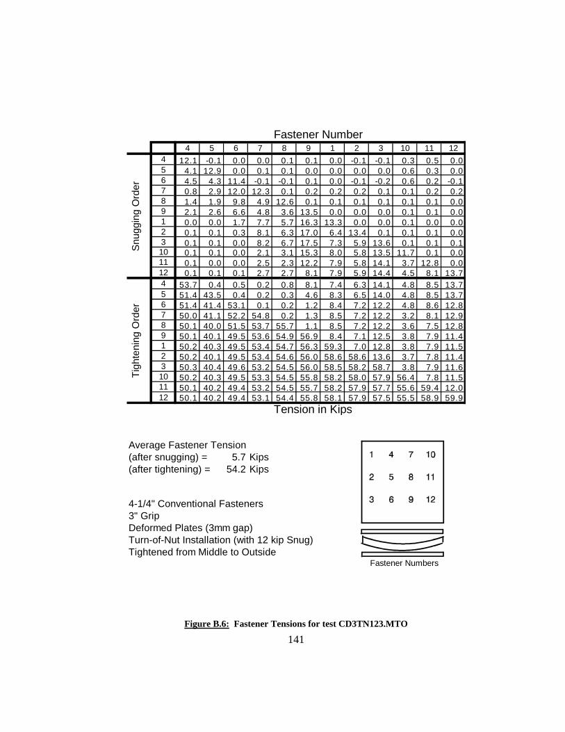
141
Fastener Number4 5 6 7 8 9 1 2 3 10 11 12
4 12.1 -0.1 0.0 0.0 0.1 0.1 0.0 -0.1 -0.1 0.3 0.5 0.05 4.1 12.9 0.0 0.1 0.1 0.0 0.0 0.0 0.0 0.6 0.3 0.06 4.5 4.3 11.4 -0.1 -0.1 0.1 0.0 -0.1 -0.2 0.6 0.2 -0.17 0.8 2.9 12.0 12.3 0.1 0.2 0.2 0.2 0.1 0.1 0.2 0.28 1.4 1.9 9.8 4.9 12.6 0.1 0.1 0.1 0.1 0.1 0.1 0.09 2.1 2.6 6.6 4.8 3.6 13.5 0.0 0.0 0.0 0.1 0.1 0.01 0.0 0.0 1.7 7.7 5.7 16.3 13.3 0.0 0.0 0.1 0.0 0.02 0.1 0.1 0.3 8.1 6.3 17.0 6.4 13.4 0.1 0.1 0.1 0.03 0.1 0.1 0.0 8.2 6.7 17.5 7.3 5.9 13.6 0.1 0.1 0.110 0.1 0.1 0.0 2.1 3.1 15.3 8.0 5.8 13.5 11.7 0.1 0.011 0.1 0.0 0.0 2.5 2.3 12.2 7.9 5.8 14.1 3.7 12.8 0.012 0.1 0.1 0.1 2.7 2.7 8.1 7.9 5.9 14.4 4.5 8.1 13.74 53.7 0.4 0.5 0.2 0.8 8.1 7.4 6.3 14.1 4.8 8.5 13.75 51.4 43.5 0.4 0.2 0.3 4.6 8.3 6.5 14.0 4.8 8.5 13.76 51.4 41.4 53.1 0.1 0.2 1.2 8.4 7.2 12.2 4.8 8.6 12.87 50.0 41.1 52.2 54.8 0.2 1.3 8.5 7.2 12.2 3.2 8.1 12.98 50.1 40.0 51.5 53.7 55.7 1.1 8.5 7.2 12.2 3.6 7.5 12.89 50.1 40.1 49.5 53.6 54.9 56.9 8.4 7.1 12.5 3.8 7.9 11.41 50.2 40.3 49.5 53.4 54.7 56.3 59.3 7.0 12.8 3.8 7.9 11.52 50.2 40.1 49.5 53.4 54.6 56.0 58.6 58.6 13.6 3.7 7.8 11.43 50.3 40.4 49.6 53.2 54.5 56.0 58.5 58.2 58.7 3.8 7.9 11.610 50.2 40.3 49.5 53.3 54.5 55.8 58.2 58.0 57.9 56.4 7.8 11.511 50.1 40.2 49.4 53.2 54.5 55.7 58.2 57.9 57.7 55.6 59.4 12.012 50.1 40.2 49.4 53.1 54.4 55.8 58.1 57.9 57.5 55.5 58.9 59.9
Tension in Kips
Average Fastener Tension (after snugging) = 5.7 Kips(after tightening) = 54.2 Kips
4-1/4" Conventional Fasteners3" GripDeformed Plates (3mm gap)Turn-of-Nut Installation (with 12 kip Snug)Tightened from Middle to Outside
Fastener Numbers
Snu
ggin
g O
rder
Tigh
teni
ng O
rder
Figure B.6: Fastener Tensions for test CD3TN123.MTO
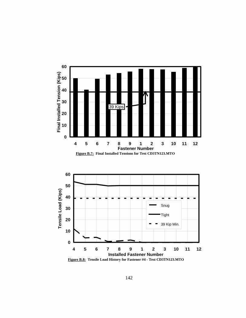
142
0
10
20
30
40
50
60
4 5 6 7 8 9 1 2 3 10 11 12Fastener Number
Fina
l Ins
talle
d Te
nsio
n (K
ips)
39 Kips
Figure B.7: Final Installed Tensions for Test CD3TN123.MTO
0
10
20
30
40
50
60
4 5 6 7 8 9 1 2 3 10 11 1Installed Fastener Number
Tens
ile L
oad
(Kip
s)
2
Snug
Tight
39 Kip Min.
Figure B.8: Tensile Load History for Fastener #4 - Test CD3TN123.MTO

143
0
10
20
30
40
50
60
4 5 6 7 8 9 1 2 3 10 11 1Installed Fastener Number
Tens
ile L
oad
(Kip
s)
2
Snug
Tight
39 Kip Min.
Figure B.9: Tensile Load History for Fastener #8 - Test CD3TN123.MTO
0
10
20
30
40
50
60
4 5 6 7 8 9 1 2 3 10 11 1Installed Fastener Number
Tens
ile L
oad
(Kip
s)
2
Snug
Tight
39 Kip Min.
Figure B.10: Tensile Load History for Fastener #2 - Test CD3TN123.MTO

144
Fastener Number
4 5 6 7 8 9 1 2 3 10 11 124 13.1 -0.1 0.0 0.0 -0.1 -0.1 -0.1 -0.1 0.0 0.1 2.0 0.05 5.2 12.6 0.0 0.0 -0.1 -0.2 -0.1 0.0 0.0 0.1 2.3 -0.16 5.4 3.8 12.6 0.0 -0.1 -0.2 -0.1 0.0 0.0 0.0 2.2 0.07 0.9 1.7 11.0 14.4 -0.1 -0.2 -0.1 0.0 0.1 -0.1 -0.1 -0.18 1.6 1.1 8.1 6.3 12.9 -0.1 -0.1 -0.1 0.0 -0.1 -0.1 -0.19 2.6 1.7 4.6 5.3 5.0 13.2 -0.1 -0.1 -0.1 -0.1 -0.2 -0.11 -0.1 -0.2 0.8 7.5 6.9 16.5 13.7 -0.1 0.0 -0.1 -0.2 -0.22 -0.1 -0.2 0.0 8.0 6.8 16.8 4.9 14.0 0.0 0.0 -0.2 -0.13 -0.1 -0.3 -0.1 8.3 7.0 15.6 4.8 7.1 13.6 -0.1 -0.2 -0.210 -0.1 -0.2 -0.1 1.0 3.1 13.5 6.2 7.8 14.1 14.1 -0.1 -0.111 -0.1 -0.3 0.0 1.6 1.0 9.1 6.5 8.1 14.7 5.7 13.8 -0.112 -0.1 -0.3 0.0 2.7 1.1 3.8 6.6 8.3 15.0 6.0 3.8 14.44 36.6 -1.4 -1.1 -1.0 -1.2 0.1 1.3 4.7 13.6 4.8 2.3 13.55 27.7 52.7 -1.1 -1.0 -1.3 -1.4 2.3 3.4 10.6 5.3 1.8 12.56 28.0 48.2 40.0 -0.9 -1.2 -1.3 2.5 4.5 8.4 5.6 2.3 11.27 23.1 46.7 39.3 52.3 -1.2 -1.3 2.9 4.7 8.5 0.3 0.5 11.28 23.3 44.9 37.7 50.1 54.9 -1.3 3.0 4.8 8.6 0.1 -0.8 7.59 23.4 45.0 32.6 50.3 52.7 56.9 3.0 5.0 9.2 0.3 -1.0 3.21 23.5 45.2 32.7 50.1 52.5 56.4 59.7 2.7 8.8 0.3 -0.9 3.32 23.8 45.4 33.0 50.2 52.5 56.4 59.1 58.9 6.5 0.4 -0.9 3.33 23.8 45.5 32.9 50.0 52.4 56.4 59.1 58.0 56.4 0.3 -0.9 3.410 23.9 45.5 33.0 49.3 52.1 56.4 59.1 58.3 56.3 53.7 -1.3 1.811 23.9 45.5 33.0 49.4 51.8 56.2 59.1 58.3 56.2 53.1 55.8 -0.612 23.9 45.4 33.2 49.5 52.0 55.6 59.0 58.3 56.3 53.1 54.4 59.0
Tension in Kips
Average Fastener Tension (after snugging) = 5.1 Kips(after tightening) = 50.0 Kips
5-1/4" Conventional Fasteners4" GripDeformed Plates (3mm gap)Turn-of-Nut Installation (with 12 kip Snug)Tightened from Middle to Outside
Fastener Numbers
Snu
ggin
g O
rder
Tigh
teni
ng O
rder
Figure B.11: Fastener Tensions for test CD3TN124.MTO
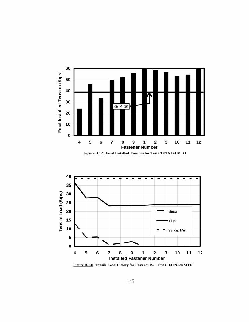
145
0
10
20
30
40
50
60
4 5 6 7 8 9 1 2 3 10 11 12Fastener Number
Fina
l Ins
talle
d Te
nsio
n (K
ips)
39 Kips
Figure B.12: Final Installed Tensions for Test CD3TN124.MTO
0
5
10
15
20
25
30
35
40
4 5 6 7 8 9 1 2 3 10 11 12Installed Fastener Number
Tens
ile L
oad
(Kip
s)
Snug
Tight
39 Kip Min.
Figure B.13: Tensile Load History for Fastener #4 - Test CD3TN124.MTO

146
0
10
20
30
40
50
60
4 5 6 7 8 9 1 2 3 10 11 1Installed Fastener Number
Tens
ile L
oad
(Kip
s)
2
Snug
Tight
39 Kip Min.
Figure B.14: Tensile Load History for Fastener #8 - Test CD3TN124.MTO
0
10
20
30
40
50
60
4 5 6 7 8 9 1 2 3 10 11 1Installed Fastener Number
Tens
ile L
oad
(Kip
s)
2
Snug
Tight
39 Kip Min.
Figure B.15: Tensile Load History for Fastener #2 - Test CD3TN124.MTO

147
Fastener Number
1 2 3 4 5 6 7 8 9 10 11 121 12.1 0.1 0.1 0.0 0.0 0.1 0.1 0.1 0.0 0.5 0.6 0.02 7.3 11.9 0.0 0.0 0.0 0.0 0.0 0.0 0.0 0.5 0.7 0.03 7.5 8.7 12.4 0.0 0.0 0.0 0.0 0.0 0.0 0.6 0.6 0.04 8.5 8.5 11.9 11.3 0.0 0.1 0.0 0.1 0.0 0.3 0.6 0.05 8.9 9.4 10.4 7.8 12.5 0.2 0.1 0.1 0.2 0.4 0.3 0.16 8.6 9.4 10.1 8.0 8.5 10.4 0.0 0.0 0.0 0.3 0.1 0.07 8.6 9.4 10.0 5.1 7.0 9.7 12.8 0.0 0.0 0.0 0.0 0.08 8.6 9.5 10.0 5.2 5.0 8.1 8.4 11.7 0.0 0.0 0.0 0.09 8.6 9.5 10.2 5.4 5.1 5.0 8.4 7.1 11.0 0.0 0.0 0.010 8.6 9.5 10.2 6.1 5.6 5.5 6.5 5.7 9.8 13.3 0.1 0.111 8.9 9.6 10.3 6.2 5.8 5.9 6.8 5.9 9.2 13.7 12.7 0.212 8.7 9.6 10.1 6.1 5.8 6.0 6.7 6.2 8.7 13.6 12.4 10.61 57.2 9.6 9.9 5.4 5.6 5.8 6.6 6.0 8.1 13.1 11.8 10.02 56.4 53.7 10.3 5.5 6.0 5.9 6.6 6.0 8.1 13.1 11.8 10.03 56.4 53.1 53.0 5.5 6.1 6.4 6.7 6.1 8.1 13.1 11.9 10.14 56.4 52.8 52.2 51.4 5.2 6.4 5.0 5.6 8.1 13.1 11.9 10.05 56.4 52.8 52.1 50.6 53.4 5.9 5.1 4.5 7.8 13.1 11.9 10.16 56.4 52.8 52.1 50.5 52.6 52.6 5.1 4.6 6.3 13.1 11.9 10.07 56.3 52.7 52.0 50.4 52.4 51.8 52.6 4.2 6.4 13.5 12.0 10.08 56.3 52.7 52.0 50.4 52.4 51.7 51.8 52.8 5.9 13.5 12.4 10.19 56.3 52.7 51.9 50.3 52.4 51.6 51.6 51.9 51.3 13.5 12.4 10.710 56.2 52.5 51.8 50.2 52.2 51.4 51.3 51.3 50.3 55.1 12.6 10.711 56.3 52.6 51.8 50.2 52.2 51.4 51.2 51.3 50.2 54.6 51.1 10.912 56.2 52.5 51.7 50.1 52.1 51.3 51.1 51.1 50.1 54.4 50.3 53.8
Tension in Kips
Average Fastener Tension (after snugging) = 8.7 Kips(after tightening) = 52.1 Kips
3-1/4" Conventional Fasteners2" GripDeformed Plates (3mm gap)Turn-of-Nut Installation (with 12 kip Snug)Tightened from Top Left to Bottom Right
Fastener Numbers
Snu
ggin
g O
rder
Tigh
teni
ng O
rder
Figure B.16: Fastener Tensions for test CD3TN122.LTR

148
0
10
20
30
40
50
60
1 2 3 4 5 6 7 8 9 10 11 12Fastener Number
Fina
l Ins
talle
d Te
nsio
n (K
ips)
39 Kips
Figure B.17: Final Installed Tensions for Test CD3TN122.LTR
0
10
20
30
40
50
60
1 2 3 4 5 6 7 8 9 10 11 1Installed Fastener Number
Tens
ile L
oad
(Kip
s)
2
Snug
Tight
39 Kip Min.
Figure B.18: Tensile Load History for Fastener #1 - Test CD3TN122.LTR

149
0
10
20
30
40
50
60
1 2 3 4 5 6 7 8 9 10 11 1Installed Fastener Number
Tens
ile L
oad
(Kip
s)
2
Snug
Tight
39 Kip Min.
Figure B.19: Tensile Load History for Fastener #5 - Test CD3TN122.LTR
0
10
20
30
40
50
60
1 2 3 4 5 6 7 8 9 10 11 1Installed Fastener Number
Tens
ile L
oad
(Kip
s)
2
Snug
Tight
39 Kip Min.
Figure B.20: Tensile Load History for Fastener #7 - Test CD3TN122.LTR

150
Fastener Number1 2 3 4 5 6 7 8 9 10 11 12
1 11.1 0.0 0.0 0.0 0.0 0.0 0.0 0.0 0.0 0.6 1.8 1.52 6.7 11.7 0.0 0.0 0.0 0.1 0.0 0.0 0.0 0.6 2.3 2.03 6.8 5.9 12.0 0.0 0.0 0.0 0.0 0.0 -0.1 0.6 2.6 2.44 2.9 2.8 9.4 11.6 0.0 0.0 0.0 0.0 -0.1 0.1 2.1 2.95 2.8 1.7 7.8 4.7 12.1 0.0 0.0 0.0 -0.1 0.0 1.6 2.06 3.1 1.8 5.4 4.9 5.1 12.0 0.0 0.0 -0.1 0.2 1.5 1.17 3.6 2.0 6.2 0.0 1.4 10.6 10.3 0.0 -0.2 -0.1 -0.1 0.08 4.1 2.1 7.4 0.0 0.4 6.1 5.1 12.2 -0.1 0.0 0.0 0.09 4.1 2.4 8.2 0.1 0.3 1.5 6.3 4.3 11.2 0.0 -0.1 -0.110 5.0 2.5 8.8 1.4 1.5 4.0 0.0 0.3 6.6 13.1 -0.1 -0.111 4.9 2.4 9.5 1.9 1.8 5.2 0.0 0.0 2.5 5.8 10.7 0.012 4.7 2.6 10.7 2.3 2.1 4.6 0.3 0.0 0.1 7.1 1.5 12.71 54.9 1.2 11.2 0.3 1.3 4.8 0.1 0.0 0.0 6.9 1.6 12.22 54.6 58.4 8.0 0.3 0.5 4.0 0.1 0.0 -0.1 6.9 1.6 12.13 54.4 58.5 57.4 0.3 0.4 0.7 0.1 0.0 -0.3 6.9 1.6 12.14 54.4 58.3 56.7 56.7 0.0 0.2 0.0 0.0 -0.4 5.4 1.6 12.35 54.3 58.0 55.4 53.7 56.0 -0.1 0.0 0.0 -0.5 5.8 1.6 11.76 54.3 58.2 55.6 53.8 53.8 58.1 0.1 0.0 -0.5 6.0 2.0 11.07 54.2 58.1 55.5 52.6 53.5 57.3 57.6 0.0 -0.5 0.3 0.8 11.18 54.1 58.0 55.3 52.7 52.4 56.5 56.4 57.1 -0.6 0.1 0.0 8.59 54.0 58.0 55.4 52.6 52.5 54.1 56.3 56.3 53.1 0.4 0.0 4.210 54.0 58.0 55.4 52.6 52.4 54.1 55.9 56.0 52.5 58.1 0.1 3.211 54.1 58.0 55.3 52.6 52.4 54.1 55.9 55.9 52.1 57.6 54.3 1.612 54.1 58.0 55.3 52.6 52.4 54.1 55.9 56.0 51.8 57.5 53.8 57.9
Tension in Kips
Average Fastener Tension (after snugging) = 4.1 Kips(after tightening) = 55.0 Kips
4-1/4" Conventional Fasteners3" GripDeformed Plates (3mm gap)Turn-of-Nut Installation (with 12 kip Snug)Tightened from Top Left to Bottom Right
Fastener Numbers
Snug
ging
Ord
erTi
ghte
ning
Ord
er
Figure B.21: Fastener Tensions for test CD3TN123.LTR

151
0
10
20
30
40
50
60
1 2 3 4 5 6 7 8 9 10 11 12Fastener Number
Fina
l Ins
talle
d Te
nsio
n (K
ips)
39 Kips
Figure B.22: Final Installed Tensions for Test CD3TN123.LTR
0
10
20
30
40
50
60
1 2 3 4 5 6 7 8 9 10 11 1Installed Fastener Number
Tens
ile L
oad
(Kip
s)
2
Snug
Tight
39 Kip Min.
Figure B.23: Tensile Load History for Fastener #1 - Test CD3TN123.LTR

152
0
10
20
30
40
50
60
1 2 3 4 5 6 7 8 9 10 11 1Installed Fastener Number
Tens
ile L
oad
(Kip
s)
2
Snug
Tight
39 Kip Min.
Figure B.24: Tensile Load History for Fastener #5 - Test CD3TN123.LTR
0
10
20
30
40
50
60
1 2 3 4 5 6 7 8 9 10 11 1Installed Fastener Number
Tens
ile L
oad
(Kip
s)
2
Snug
Tight
39 Kip Min.
Figure B.25: Tensile Load History for Fastener #7 - Test CD3TN123.LTR

153
Fastener Number
1 2 3 4 5 6 7 8 9 10 11 121 13.0 0.0 0.0 0.0 0.0 0.0 0.0 0.0 0.0 0.3 0.2 1.72 8.2 11.9 0.0 0.0 0.0 0.0 0.0 0.0 0.0 0.5 0.2 2.23 8.0 6.4 10.7 0.0 0.0 0.0 0.0 0.0 0.0 0.7 0.3 2.24 2.6 4.0 9.4 12.2 0.0 0.0 0.0 0.0 0.0 0.1 0.0 1.65 2.3 2.7 6.8 4.9 13.4 0.0 0.0 0.0 -2.0 0.0 0.0 0.66 2.8 2.9 3.7 4.7 5.9 10.8 0.0 0.0 -2.0 0.0 0.0 0.07 2.8 4.1 5.7 0.1 2.0 8.3 11.8 0.0 -2.0 0.0 0.0 0.08 3.2 4.3 6.7 0.1 0.9 4.2 5.8 10.9 -1.9 0.0 0.0 0.09 3.5 5.1 6.8 0.2 0.7 1.0 6.0 4.4 9.2 0.0 0.0 0.010 5.0 5.9 8.2 1.0 1.6 2.5 0.2 1.1 6.1 12.0 0.0 0.011 5.2 6.2 9.6 1.4 1.9 3.4 0.3 0.0 1.5 4.1 12.6 0.012 5.2 6.6 10.7 1.7 2.0 3.0 0.5 0.0 -1.3 4.7 4.2 10.91 56.9 0.6 9.1 -0.4 0.1 1.8 -0.2 -0.1 -1.4 4.5 3.9 10.52 52.2 58.0 1.5 -0.3 -0.1 0.1 -0.1 -0.1 -1.1 4.3 3.4 10.73 51.8 53.5 56.9 -0.3 -0.1 -0.2 -0.1 -0.1 -1.1 4.5 3.5 9.14 48.5 51.7 55.4 42.5 -0.1 -0.2 -0.1 -0.1 -1.0 3.4 3.0 9.45 49.0 51.7 53.2 35.0 51.8 -0.2 -0.1 -0.1 -1.0 3.6 2.4 8.56 49.0 52.4 51.8 34.8 45.8 52.8 -0.1 -0.1 -1.0 4.0 2.5 6.67 49.2 52.5 51.9 29.9 44.2 52.1 34.6 -0.1 -1.0 -0.1 0.6 6.28 49.2 52.6 52.0 30.3 42.1 50.0 25.4 56.0 -0.9 -0.1 -0.1 1.29 49.2 52.6 52.3 30.6 42.6 45.0 24.2 47.4 48.4 -0.1 -0.1 -0.110 49.1 52.6 52.2 31.2 42.7 45.2 18.3 43.5 45.4 26.9 -0.1 -0.111 49.1 52.6 52.2 31.2 42.7 45.2 19.0 43.1 44.0 25.4 53.3 -0.112 49.1 52.6 52.2 31.2 42.8 45.3 19.1 43.4 43.9 25.5 51.8 48.2
Tension in Kips
Average Fastener Tension (after snugging) = 4.0 Kips(after tightening) = 42.1 Kips
5-1/4" Conventional Fasteners4" GripDeformed Plates (3mm gap)Turn-of-Nut Installation (with 12 kip Snug)Tightened from Top Left to Bottom Right
Fastener Numbers
Snu
ggin
g O
rder
Tigh
teni
ng O
rder
Figure B.26: Fastener Tensions for test CD3TN124.LTR

154
0
10
20
30
40
50
60
1 2 3 4 5 6 7 8 9 10 11 12Fastener Number
Fina
l Ins
talle
d Te
nsio
n (K
ips)
39 Kips
Figure B.27: Final Installed Tensions for Test CD3TN124.LTR
0
10
20
30
40
50
60
1 2 3 4 5 6 7 8 9 10 11 12Installed Fastener Number
Tens
ile L
oad
(Kip
s)
Snug
Tight
39 Kip Min.
Figure B.28: Tensile Load History for Fastener #1 - Test CD3TN124.LTR

155
0
10
20
30
40
50
60
1 2 3 4 5 6 7 8 9 10 11 1Installed Fastener Number
Tens
ile L
oad
(Kip
s)
2
Snug
Tight
39 Kip Min.
Figure B.29: Tensile Load History for Fastener #5 - Test CD3TN124.LTR
0
5
10
15
20
25
30
35
40
1 2 3 4 5 6 7 8 9 10 11 1Installed Fastener Number
Tens
ile L
oad
(Kip
s)
2
Snug
Tight
39 Kip Min.
Figure B.30: Tensile Load History for Fastener #7 - CD3TN124.LTR

156
Fastener Number
1 2 3 10 11 12 4 5 6 7 8 91 11.4 0.0 0.0 0.0 0.0 0.1 0.0 0.0 0.0 0.0 0.0 0.02 6.8 11.1 0.0 0.0 0.1 0.0 0.0 0.0 0.1 0.0 0.0 0.03 6.3 6.1 11.3 0.0 0.0 -0.1 -0.1 -0.1 0.0 -0.1 -0.1 0.010 5.3 5.3 9.3 14.4 -0.1 -0.1 -0.1 -0.1 -0.1 -0.1 -0.1 -0.111 5.4 5.1 8.2 12.5 10.7 -0.1 -0.1 -0.1 -0.1 0.0 -0.1 -0.112 5.4 5.0 6.8 12.4 7.5 10.4 -0.1 -0.1 -0.2 -0.1 -0.1 -0.14 6.2 5.0 6.8 12.0 7.1 10.0 10.9 -0.1 -0.2 -0.1 -0.1 -0.15 6.4 5.1 6.3 12.0 6.8 9.2 8.5 7.8 -0.2 -0.1 -0.1 -0.16 6.4 5.3 5.8 12.1 6.9 8.6 8.8 4.7 11.6 -0.1 -0.1 -0.17 6.4 5.3 5.8 12.6 6.9 8.6 5.5 3.9 11.4 11.0 -0.1 -0.18 6.4 5.4 5.8 12.8 7.1 8.8 5.2 2.6 10.0 9.0 11.4 -0.19 6.4 5.5 6.0 12.7 7.3 9.3 5.3 2.5 6.6 9.0 9.6 11.71 43.1 5.7 5.9 12.6 7.2 9.1 5.8 2.6 BG 8.8 9.3 11.12 43.1 54.8 6.5 12.6 7.2 9.1 5.9 2.9 BG 8.8 9.4 11.13 43.1 54.0 52.3 12.6 7.2 9.2 5.9 2.9 BG 8.8 9.4 11.210 43.1 53.8 51.8 52.9 7.6 9.2 5.9 2.9 BG 9.2 9.5 11.211 43.1 53.5 51.4 52.1 55.0 9.6 5.9 2.9 BG 9.2 9.9 11.212 43.1 53.5 51.3 52.1 54.5 54.4 5.9 2.9 BG 9.2 10.0 11.74 43.1 53.5 51.2 52.0 54.2 53.6 54.6 2.3 BG 7.3 9.4 11.85 43.1 53.5 51.1 51.9 54.0 53.5 53.7 49.4 BG 7.4 7.9 11.56 43.1 53.4 51.2 51.8 54.0 53.4 53.5 48.9 BG 7.5 8.1 9.97 43.1 53.4 51.1 51.8 53.9 53.4 53.4 48.8 BG 53.6 7.5 10.08 43.0 53.4 51.0 51.7 53.9 53.3 53.4 48.8 BG 53.0 55.3 9.79 43.0 53.4 51.0 51.7 53.9 53.4 53.4 48.8 BG 52.8 54.5 53.4
Tension in Kips
Average Fastener Tension (after snugging) = 7.7 Kips(after tightening) = 51.8 Kips
3-1/4" Conventional Fasteners2" GripDeformed Plates (3mm gap)Turn-of-Nut Installation (with 12 kip Snug)Tightened from Outside to Middle
Fastener Numbers
Snu
ggin
g O
rder
Tigh
teni
ng O
rder
Figure B.31: Fastener Tensions for test CD3TN122.OTM
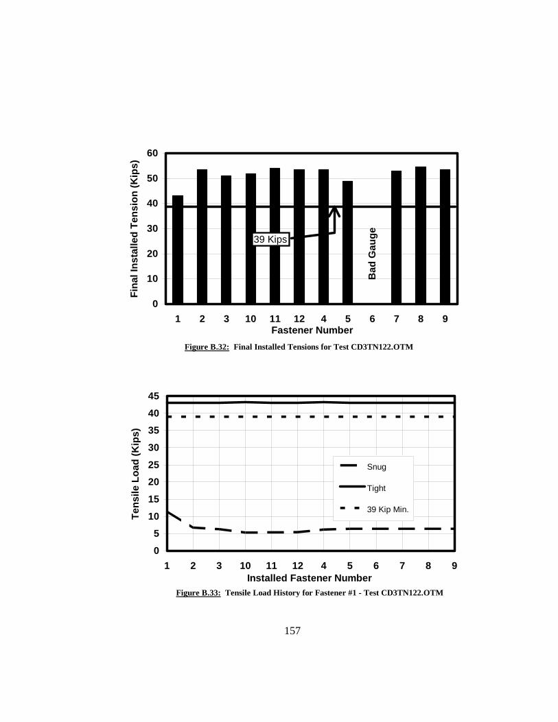
157
0
10
20
30
40
50
60
1 2 3 10 11 12 4 5 6 7 8 9Fastener Number
Fina
l Ins
talle
d Te
nsio
n (K
ips)
39 Kips
Bad
Gau
ge
Figure B.32: Final Installed Tensions for Test CD3TN122.OTM
0
510
15
2025
30
3540
45
1 2 3 10 11 12 4 5 6 7 8 9Installed Fastener Number
Tens
ile L
oad
(Kip
s)
Snug
Tight
39 Kip Min.
Figure B.33: Tensile Load History for Fastener #1 - Test CD3TN122.OTM

158
0
10
20
30
40
50
60
1 2 3 10 11 12 4 5 6 7 8Installed Fastener Number
Tens
ile L
oad
(Kip
s)
9
Snug
Tight
39 Kip Min.
Figure B.34: Tensile Load History for Fastener #10 - Test CD3TN122.OTM
05
101520253035404550
1 2 3 10 11 12 4 5 6 7 8 9Installed Fastener Number
Tens
ile L
oad
(Kip
s)
Snug
Tight
39 Kip Min.
Figure B.35: Tensile Load History for Fastener #5 - Test CD3TN122.OTM

159
Fastener Number1 2 3 10 11 12 4 5 6 7 8 9
1 13.3 0.1 0.0 2.0 0.0 1.6 0.0 0.0 0.0 0.0 0.0 0.02 8.8 9.6 0.0 2.4 0.0 2.3 0.0 0.0 0.0 0.0 0.0 0.03 8.6 5.2 13.4 2.6 0.0 2.8 0.0 0.0 0.0 0.0 0.0 0.010 7.7 4.5 11.9 10.8 0.0 0.0 0.0 0.0 0.0 0.0 0.0 0.011 7.7 4.2 11.5 1.0 12.7 0.0 0.0 0.0 0.0 0.0 0.0 0.012 7.5 4.2 11.2 2.5 1.5 12.2 0.0 0.0 0.0 0.0 0.0 0.04 3.1 3.3 10.1 1.9 1.5 11.9 10.9 0.0 0.0 0.0 0.0 0.05 3.5 2.5 8.4 2.1 1.3 11.3 4.6 12.0 0.0 0.0 0.1 0.06 3.7 2.6 6.0 2.3 1.6 10.6 4.7 6.6 9.9 0.0 0.0 0.07 4.7 2.8 6.2 0.0 0.4 10.7 1.1 4.0 8.7 11.9 0.0 0.08 4.9 2.9 6.5 0.0 0.0 9.0 0.8 2.6 6.3 8.4 11.6 0.09 4.9 3.3 6.8 0.0 0.3 6.7 0.9 2.3 3.2 8.9 8.7 10.91 57.9 2.2 7.3 0.0 0.3 6.9 0.6 2.6 3.5 9.1 8.7 10.32 57.4 56.5 5.5 0.0 0.3 7.0 0.7 2.1 3.5 9.2 8.8 10.43 57.3 56.8 59.4 0.1 0.4 7.2 0.8 2.5 2.4 9.3 8.9 10.510 57.0 56.3 58.5 25.2 0.0 3.0 1.4 3.0 2.7 3.8 5.7 11.111 56.9 56.1 58.3 24.7 56.8 0.2 1.5 3.2 2.9 4.3 4.6 9.912 56.8 56.1 58.3 24.7 56.2 55.0 1.5 3.4 2.8 4.5 5.0 5.94 57.1 56.3 58.2 24.7 56.2 54.4 59.7 1.6 2.7 0.9 3.0 6.05 57.1 56.2 58.1 24.7 56.1 54.2 58.3 56.4 1.3 0.7 1.1 4.36 57.1 56.4 58.2 24.7 56.1 54.1 58.3 55.2 54.3 0.8 1.1 1.67 57.1 56.3 58.2 24.8 56.2 54.0 57.2 54.9 53.8 55.6 0.7 1.68 57.0 56.2 58.1 24.9 56.3 54.0 57.2 53.8 53.2 55.0 58.4 1.39 57.0 56.2 58.1 24.9 56.3 54.2 57.2 53.9 50.7 54.8 57.7 57.2
Tension in Kips
Average Fastener Tension (after snugging) = 4.7 Kips(after tightening) = 53.2 Kips
4-1/4" Conventional Fasteners3" GripDeformed Plates (3mm gap)Turn-of-Nut Installation (with 12 kip Snug)Tightened from Outside to Middle
Fastener Numbers
Snu
ggin
g O
rder
Tigh
teni
ng O
rder
Figure B.36: Fastener Tensions for test CD3TN123.OTM

160
0
10
20
30
40
50
60
1 2 3 10 11 12 4 5 6 7 8 9Fastener Number
Fina
l Ins
talle
d Te
nsio
n (K
ips)
39 Kips
Figure B.37: Final Installed Tensions for Test CD3TN123.OTM
0
10
20
30
40
50
60
1 2 3 10 11 12 4 5 6 7 8 9Installed Fastener Number
Tens
ile L
oad
(Kip
s)
Snug
Tight
39 Kip Min.
Figure B.38: Tensile Load History for Fastener #1 - Test CD3TN123.OTM

161
0
5
10
15
20
25
30
35
40
1 2 3 10 11 12 4 5 6 7 8 9Installed Fastener Number
Tens
ile L
oad
(Kip
s)
Snug
Tight
39 Kip Min.
Figure B.39: Tensile Load History for Fastener #10 - Test CD3TN123.OTM
0
10
20
30
40
50
60
1 2 3 10 11 12 4 5 6 7 8Installed Fastener Number
Tens
ile L
oad
(Kip
s)
9
Snug
Tight
39 Kip Min.
Figure B.40: Tensile Load History for Fastener #5 - Test CD3TN123.OTM

162
Fastener Number
1 2 3 10 11 12 4 5 6 7 8 91 12.1 0.0 0.0 0.2 0.1 1.8 0.0 0.0 0.0 0.0 0.0 0.02 7.2 13.1 0.0 0.2 0.1 2.3 0.0 0.0 0.1 0.0 0.0 0.03 7.0 7.8 12.1 0.2 0.0 2.5 0.0 -0.1 0.0 0.0 0.0 0.010 5.5 7.5 13.0 11.5 -0.1 -0.1 -0.1 -0.1 -0.1 -0.1 -0.1 -0.111 5.8 7.3 13.0 2.9 12.6 0.0 0.0 0.0 0.0 0.0 0.0 0.012 6.0 7.6 12.5 3.7 2.4 11.0 -0.1 -0.1 -0.1 -0.1 0.0 -0.14 2.6 5.6 12.1 2.5 2.0 10.4 11.7 -0.1 0.0 0.0 0.0 0.05 2.9 4.1 10.4 2.5 1.7 9.4 6.1 11.3 0.0 0.0 0.0 0.06 3.4 4.3 7.5 2.7 1.9 7.8 5.6 5.1 9.9 0.0 0.0 0.07 3.8 4.9 8.0 0.7 0.8 7.8 1.5 2.6 8.3 11.4 0.0 -0.18 4.0 5.0 8.4 0.7 0.2 6.0 1.0 1.3 6.1 7.1 11.0 -0.19 4.2 5.5 8.4 0.9 0.2 3.1 1.0 0.8 2.6 7.2 6.1 12.81 58.0 0.5 6.9 1.5 0.5 3.6 0.2 0.3 2.5 4.8 5.0 12.12 55.7 57.8 1.8 1.6 0.6 4.2 0.2 0.0 1.1 4.1 3.8 11.13 55.8 56.0 57.1 1.7 0.8 4.8 0.2 0.0 0.0 4.3 3.6 7.410 55.7 55.9 56.7 15.6 0.0 1.1 0.1 0.0 0.1 0.1 0.8 7.711 55.6 55.7 56.5 1.4 25.5 -0.1 0.1 -0.2 0.4 0.1 -0.1 1.312 55.7 55.7 55.6 2.1 7.4 28.6 0.2 -0.2 0.1 0.5 -0.1 -0.14 54.3 55.2 55.5 1.6 6.4 27.8 49.2 -0.2 0.0 0.0 0.0 0.05 54.7 55.2 54.6 1.7 5.9 26.5 43.5 56.2 -0.1 -0.1 -0.1 0.06 54.7 55.6 53.9 1.7 6.3 25.2 43.6 52.3 49.2 -0.1 -0.1 -0.17 54.8 55.7 53.9 0.0 2.6 24.4 39.1 51.0 48.6 48.3 -0.2 -0.18 54.8 55.7 53.9 0.0 1.6 22.9 39.1 49.2 47.3 45.9 54.5 -0.19 54.9 55.8 54.1 0.0 1.9 22.6 39.2 49.2 43.2 46.0 53.1 54.6
Tension in Kips
Average Fastener Tension (after snugging) = 4.4 Kips(after tightening) = 39.5 Kips
5-1/4" Conventional Fasteners4" GripDeformed Plates (3mm gap)Turn-of-Nut Installation (with 12 kip Snug)Tightened from Outside to Middle
Fastener Numbers
Snu
ggin
g O
rder
Tigh
teni
ng O
rder
Figure B.41: Fastener Tensions for test CD3TN124.OTM

163
0
10
20
30
40
50
60
1 2 3 10 11 12 4 5 6 7 8 9Fastener Number
Fina
l Ins
talle
d Te
nsio
n (K
ips)
39 Kips
Figure B.42: Final Installed Tensions for Test CD3TN124.OTM
0
10
20
30
40
50
60
1 2 3 10 11 12 4 5 6 7 8 9Installed Fastener Number
Tens
ile L
oad
(Kip
s)
Snug
Tight
39 Kip Min.
Figure B.43: Tensile Load History for Fastener #1 - Test CD3TN124.OTM

164
0
5
10
15
20
25
30
35
40
1 2 3 10 11 12 4 5 6 7 8Installed Fastener Number
Tens
ile L
oad
(Kip
s)
9
Snug
Tight
39 Kip Min.
Figure B.44: Tensile Load History for Fastener #10 - Test CD3TN124.OTM
0
10
20
30
40
50
60
1 2 3 10 11 12 4 5 6 7 8 9Installed Fastener Number
Tens
ile L
oad
(Kip
s)
Snug
Tight
39 Kip Min.
Figure B.45: Tensile Load History for Fastener #5 - Test CD3TN124.OTM

165
Fastener Number4 5 6 7 8 9 1 2 3 10 11 12
4 24.5 0.1 0.1 0.1 0.1 0.1 0.1 0.0 0.1 0.1 0.1 0.75 18.0 22.2 0.0 0.0 -0.1 -0.1 0.0 0.0 0.0 0.0 0.0 0.46 18.1 19.3 25.6 0.0 0.0 0.0 0.0 0.0 0.1 0.1 0.1 0.47 18.2 19.2 25.3 24.5 0.1 0.1 0.0 0.1 0.1 0.1 0.0 0.18 18.2 19.4 25.3 20.1 25.4 -0.1 -0.1 0.0 0.0 -0.1 -0.1 -0.19 18.2 19.6 25.4 19.9 21.9 23.2 0.0 0.0 -0.1 0.0 -0.1 -0.11 18.4 19.4 25.0 20.0 21.9 22.7 23.7 0.1 0.1 0.1 0.1 0.12 18.5 19.7 24.7 20.0 22.0 22.8 23.6 23.6 0.1 0.2 0.1 0.23 18.5 19.8 25.0 19.9 21.9 22.7 23.5 23.6 21.6 0.1 0.1 0.110 18.5 19.8 25.1 18.5 21.3 22.4 23.4 23.5 21.3 27.4 0.1 0.211 18.5 19.8 25.1 18.6 21.4 22.0 23.4 23.5 21.2 27.5 27.6 0.212 18.5 19.9 25.1 18.7 21.5 22.3 23.4 23.5 21.2 27.4 27.5 22.44 45.1 19.9 25.0 18.7 21.5 22.2 23.0 23.2 20.8 27.0 27.0 21.55 44.6 39.4 25.0 18.7 21.5 22.2 23.0 23.2 20.8 27.0 27.0 21.56 44.6 39.2 41.7 18.8 21.6 22.2 23.0 23.2 20.8 27.0 27.0 21.57 44.5 39.1 41.4 42.2 21.5 22.2 23.0 23.2 20.8 27.0 27.0 21.58 44.5 39.0 41.3 41.9 44.2 22.2 23.0 23.2 20.8 27.0 27.0 21.49 44.4 39.0 41.2 41.7 43.8 42.3 23.0 23.2 20.8 27.0 27.0 21.51 44.4 39.0 41.2 41.7 43.7 41.9 38.7 23.2 20.8 27.1 27.1 21.52 44.4 39.0 41.2 41.7 43.6 41.7 38.4 42.2 20.8 27.0 27.1 21.53 44.4 38.9 41.2 41.6 43.5 41.7 38.3 41.9 37.6 27.0 27.1 21.610 44.4 38.9 41.1 41.6 43.4 41.5 38.2 41.7 37.1 41.3 27.0 21.511 44.3 38.9 41.1 41.6 43.4 41.5 38.2 41.7 37.1 41.1 40.8 21.612 44.4 38.9 41.1 41.6 43.4 41.5 38.2 41.7 37.0 41.0 40.5 41.14 44.6 38.8 40.9 41.4 43.2 41.3 37.8 41.3 36.7 40.6 40.0 40.35 44.5 42.1 40.9 41.4 43.1 41.2 37.8 41.3 36.7 40.6 40.0 40.36 44.5 42.0 41.6 41.3 43.2 41.3 37.8 41.3 36.7 40.6 40.0 40.37 44.5 42.0 41.5 42.9 43.2 41.2 37.8 41.3 36.7 40.6 40.0 40.38 44.5 41.9 41.5 42.9 44.0 41.2 37.8 41.3 36.7 40.6 40.0 40.39 44.5 42.0 41.5 42.9 44.0 42.8 37.9 41.3 36.7 40.6 40.0 40.31 44.5 41.9 41.5 42.8 44.0 42.7 41.8 41.3 36.7 40.6 40.0 40.32 44.5 41.9 41.4 42.8 43.9 42.7 41.6 43.7 36.7 40.5 39.9 40.23 44.5 41.9 41.4 42.8 43.9 42.6 41.5 43.6 39.7 40.6 40.0 40.210 44.4 41.8 41.4 42.7 43.8 42.6 41.3 43.4 39.4 42.5 39.9 40.211 44.5 41.8 41.4 42.7 43.8 42.6 41.3 43.5 39.5 42.4 43.3 40.212 44.4 41.8 41.4 42.7 43.8 42.6 41.3 43.4 39.4 42.4 43.2 41.5
Tension in KipsAverage Fastener Tension (after snugging) = 22.6 Kips(after tightening) = 40.9 Kips(after touch-up) = 42.3 Kips
3-1/4" Conventional Fasteners2" GripDeformed Plates (3mm gap)Cal. Wrench Installation (with 25 kip Snug)Tightened from Middle to Outside
Fastener Numbers
Snu
ggin
g O
rder
Tigh
teni
ng O
rder
Touc
h-up
Ord
er
Figure B.46: Fastener Tensions for test CD3CW252.MTO
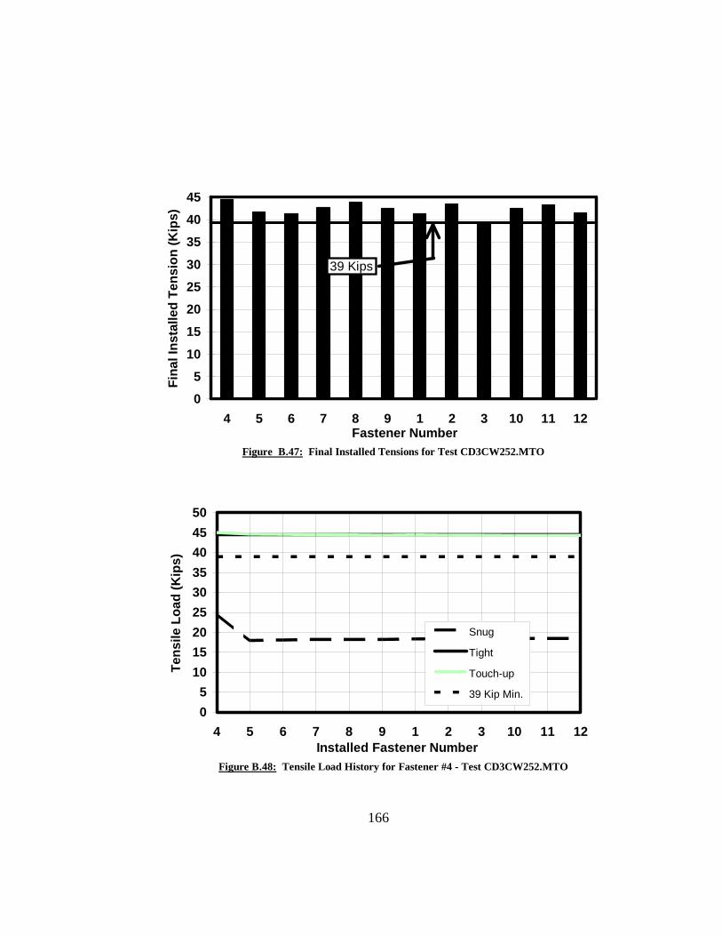
166
0
5
10
15
20
25
30
35
40
45
4 5 6 7 8 9 1 2 3 10 11 12Fastener Number
Fina
l Ins
talle
d Te
nsio
n (K
ips)
39 Kips
Figure B.47: Final Installed Tensions for Test CD3CW252.MTO
05
101520253035404550
4 5 6 7 8 9 1 2 3 10 11 12Installed Fastener Number
Tens
ile L
oad
(Kip
s)
Snug
Tight
Touch-up
39 Kip Min.
Figure B.48: Tensile Load History for Fastener #4 - Test CD3CW252.MTO
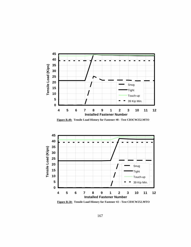
167
05
1015202530354045
4 5 6 7 8 9 1 2 3 10 11 1Installed Fastener Number
Tens
ile L
oad
(Kip
s)
2
Snug
Tight
Touch-up
39 Kip Min.
Figure B.49: Tensile Load History for Fastener #8 - Test CD3CW252.MTO
05
1015202530354045
4 5 6 7 8 9 1 2 3 10 11 1Installed Fastener Number
Tens
ile L
oad
(Kip
s)
2
Snug
Tight
Touch-up
39 Kip Min.
Figure B.50: Tensile Load History for Fastener #2 - Test CD3CW252.MTO

168
Fastener Number4 5 6 7 8 9 1 2 3 10 11 12
4 23.3 0.2 0.2 0.2 0.1 0.2 0.1 0.2 0.1 0.2 0.4 0.35 10.5 24.2 0.2 0.2 0.2 0.2 0.2 0.2 0.2 0.2 0.2 0.36 10.8 11.1 26.0 0.1 0.1 0.2 0.2 0.2 0.2 0.2 0.2 0.37 10.4 9.9 24.4 24.1 0.2 0.2 0.2 0.2 0.1 0.2 0.2 0.38 12.1 9.9 23.1 15.1 29.0 0.2 0.2 0.3 0.2 0.2 0.2 0.49 12.5 11.7 20.3 14.7 21.5 23.2 0.1 0.3 0.1 0.2 0.2 0.31 4.8 5.9 17.0 15.9 22.1 23.7 25.0 0.2 0.2 0.2 0.2 0.42 5.6 4.9 13.6 15.9 22.4 24.4 23.5 26.6 0.2 0.2 0.2 0.43 5.7 5.7 11.4 15.9 22.5 25.1 23.6 23.8 26.7 0.3 0.3 0.410 7.0 6.3 12.3 9.3 16.4 21.4 23.5 23.7 26.3 27.2 0.3 0.511 7.0 6.5 12.8 9.9 15.2 18.2 23.4 23.7 26.1 26.5 28.7 0.512 7.0 6.6 13.2 9.9 15.9 16.0 23.4 23.7 26.1 26.4 28.1 30.04 41.5 6.0 12.9 20.4 15.2 16.3 23.0 23.5 BG 25.9 27.5 28.45 41.0 39.9 12.3 22.6 13.5 16.0 23.2 23.5 BG 25.9 27.6 28.56 41.0 39.2 37.4 23.5 13.5 13.5 23.2 23.6 BG 25.9 27.7 28.47 40.2 39.1 36.9 45.7 13.6 13.6 23.2 23.6 BG 25.8 27.8 28.48 40.2 38.8 36.7 47.1 40.6 13.6 23.2 23.6 BG 25.9 27.8 28.59 40.2 38.8 34.5 46.9 40.3 41.8 23.1 23.6 BG 25.9 27.8 28.61 40.2 38.8 34.5 49.2 40.2 41.6 39.3 23.8 BG 25.9 27.9 28.72 40.2 38.7 34.6 47.5 40.2 41.5 39.2 41.8 BG 25.9 27.9 28.73 40.2 38.8 34.5 47.5 40.1 41.4 39.0 41.4 BG 25.9 27.8 28.710 40.2 38.8 34.5 48.0 40.1 41.4 39.0 41.3 BG 38.8 27.9 28.711 40.1 38.7 34.5 47.4 40.1 41.4 38.9 41.2 BG 38.4 43.3 28.712 40.1 38.7 34.5 47.4 40.1 41.4 38.9 41.1 BG 38.2 43.0 46.94 39.9 38.3 34.1 39.3 39.6 40.7 38.2 40.3 BG 37.1 42.2 44.55 39.8 38.5 34.1 38.8 39.6 40.7 38.2 40.3 BG 37.1 42.2 44.66 39.8 38.4 37.4 35.7 39.6 40.6 38.2 40.3 BG 37.1 42.2 44.57 39.8 38.4 37.1 38.0 39.6 40.6 38.2 40.3 BG 37.1 42.2 44.68 39.8 38.4 37.1 35.3 41.5 40.7 38.2 40.3 BG 37.1 42.2 44.69 39.9 38.4 37.1 36.8 41.5 41.5 38.2 40.3 BG 37.1 42.2 44.61 39.8 38.4 37.1 38.4 41.5 41.4 39.4 40.3 BG 37.2 42.3 44.62 39.8 38.4 37.1 37.5 41.4 41.4 39.4 40.7 BG 37.1 42.2 44.63 39.8 38.4 37.1 35.5 41.4 41.4 39.3 40.6 BG 37.1 42.2 44.610 39.8 38.4 37.1 33.6 41.4 41.4 39.3 40.6 BG 37.8 42.2 44.611 39.8 38.4 37.1 32.2 41.4 41.4 39.3 40.6 BG 37.8 42.4 44.612 39.8 38.4 37.0 38.4 41.4 41.4 39.3 40.6 BG 37.8 42.4 45.4
Tension in KipsAverage Fastener Tension (after snugging) = 18.9 Kips(after tightening) = 41.0 Kips(after touch-up) = 40.2 Kips
4-1/4" Conventional Fasteners3" GripDeformed Plates (3mm gap)Cal. Wrench Installation (with 25 kip Snug)Tightened from Middle to Outside
Fastener Numbers
Snu
ggin
g O
rder
Tigh
teni
ng O
rder
Touc
h-up
Ord
er
Figure B.51: Fastener Tensions for test CD3CW253.MTO

169
05
101520253035404550
4 5 6 7 8 9 1 2 3 10 11 12Fastener Number
Fina
l Ins
talle
d Te
nsio
n (K
ips)
39 Kips
Bad
Gau
ge
Figure B.52: Final Installed Tensions for Test CD3CW253.MTO
0
510
1520
2530
3540
45
4 5 6 7 8 9 1 2 3 10 11 1Installed Fastener Number
Tens
ile L
oad
(Kip
s)
2
Snug
Tight
Touch-up
39 Kip Min.
Figure B.53: Tensile Load History for Fastener #4 - Test CD3CW253.MTO

170
0
5
10
15
20
25
30
35
40
45
4 5 6 7 8 9 1 2 3 10 11 1Installed Fastener Number
Tens
ile L
oad
(Kip
s)
2
Snug
Tight
Touch-up
39 Kip Min.
Figure B.54: Tensile Load History for Fastener #8 - Test CD3CW253.MTO
0
5
10
15
20
25
30
35
40
45
4 5 6 7 8 9 1 2 3 10 11 1Installed Fastener Number
Tens
ile L
oad
(Kip
s)
2
Snug
Tight
Touch-up
39 Kip Min.
Figure B.55: Tensile Load History for Fastener #2 - Test CD3CW253.MTO

171
Fastener Number4 5 6 7 8 9 1 2 3 10 11 12
4 25.9 0.2 0.2 0.2 0.1 0.2 0.1 0.1 0.2 0.9 0.4 2.65 10.1 24.2 0.3 0.3 0.2 0.3 0.2 0.2 0.2 1.9 0.6 1.96 10.1 7.5 22.8 0.2 0.2 0.3 0.2 0.2 0.2 2.4 0.6 1.47 2.4 5.4 22.7 26.8 0.2 0.3 0.2 0.2 0.2 0.3 0.3 0.38 3.4 4.5 18.7 11.4 27.7 0.4 0.2 0.3 0.3 0.4 0.3 0.39 4.9 5.8 13.6 10.2 15.9 23.7 0.2 0.2 0.2 0.3 0.3 0.21 0.3 0.3 5.5 16.0 20.3 28.7 23.3 0.3 0.3 0.4 0.4 0.32 0.3 0.1 0.7 17.6 22.0 31.2 8.9 24.5 0.3 0.4 0.4 0.33 0.2 0.0 0.2 18.1 23.2 30.8 9.0 10.0 26.2 0.3 0.3 0.310 0.2 0.7 0.3 4.7 13.1 24.9 10.3 9.8 26.0 23.9 0.3 0.311 0.2 0.8 0.3 5.8 8.1 18.6 10.1 9.6 26.4 13.0 26.2 0.312 0.2 0.7 0.3 6.3 8.0 12.4 9.9 9.5 26.3 14.6 18.2 25.24 42.6 0.2 0.6 1.1 4.4 13.0 7.5 9.4 26.4 14.6 18.5 24.85 39.1 40.3 0.5 0.8 2.4 10.0 8.1 9.5 25.9 14.7 18.4 24.86 39.2 37.7 41.1 0.9 2.1 5.2 8.2 10.3 24.6 14.8 18.5 24.27 35.7 36.9 40.7 49.6 1.4 5.2 8.4 10.5 24.7 12.8 18.7 24.38 35.6 35.4 39.8 47.9 48.0 4.4 8.4 10.5 24.8 13.3 18.5 24.49 35.7 35.3 35.8 47.8 46.6 44.0 8.4 10.7 25.0 13.4 18.8 23.81 35.7 35.5 35.9 47.8 46.5 43.5 40.5 8.9 24.8 13.4 18.9 23.82 35.9 35.6 36.1 47.8 46.5 43.5 40.2 40.3 23.9 13.4 18.9 23.83 35.9 35.7 35.9 47.8 46.5 43.4 40.1 39.7 40.1 13.5 18.9 23.910 35.9 35.7 36.0 47.5 46.6 43.4 40.1 39.7 39.9 41.8 18.9 23.911 35.9 35.7 36.0 47.5 46.5 43.5 40.1 39.6 39.9 41.5 41.8 23.612 35.9 35.7 36.0 47.6 46.5 43.3 40.1 39.6 39.8 41.4 41.4 42.54 38.9 34.3 34.8 45.7 44.9 41.4 38.7 37.8 38.2 39.3 39.5 40.25 38.9 37.8 34.9 45.8 45.0 41.5 38.8 37.9 38.3 39.4 39.6 40.46 38.9 37.7 39.0 45.8 45.0 41.2 38.8 37.9 38.3 39.4 39.6 40.37 38.8 37.6 38.9 49.4 44.9 41.1 38.8 37.8 38.2 39.3 39.6 40.38 38.9 37.8 39.1 49.5 46.0 41.4 38.9 38.0 38.4 39.6 39.8 40.59 38.9 37.7 38.9 49.4 45.9 42.8 38.9 37.9 38.3 39.5 39.7 40.41 38.7 37.6 38.8 49.2 45.8 42.6 40.2 37.8 38.2 39.3 39.5 40.32 38.8 37.6 38.8 49.2 45.8 42.6 40.1 40.4 38.2 39.4 39.6 40.33 38.6 37.4 38.6 49.0 45.6 42.4 39.9 40.1 39.3 39.1 39.4 40.110 38.6 37.4 38.6 49.0 45.6 42.3 39.9 40.1 39.2 42.0 39.3 40.111 38.7 37.6 38.8 49.2 45.8 42.6 40.1 40.3 39.3 42.2 40.8 40.312 38.6 37.5 38.6 49.0 45.6 42.4 39.9 40.1 39.2 41.9 40.6 41.9
Tension in KipsAverage Fastener Tension (after snugging) = 11.0 Kips(after tightening) = 40.8 Kips(after touch-up) = 41.3 Kips
5-1/4" Conventional Fasteners4" GripDeformed Plates (3mm gap)Cal. Wrench Installation (with 25 kip Snug)Tightened from Middle to Outside
Fastener Numbers
Snu
ggin
g O
rder
Tigh
teni
ng O
rder
Touc
h-up
Ord
er
Figure B.56: Fastener Tensions for test CD3CW254.MTO

172
05
101520253035404550
4 5 6 7 8 9 1 2 3 10 11 12Fastener Number
Fina
l Ins
talle
d Te
nsio
n (K
ips)
39 Kips
Figure B.57: Final Installed Tensions for Test CD3CW254.MTO
0
510
1520
2530
3540
45
4 5 6 7 8 9 1 2 3 10 11 1Installed Fastener Number
Tens
ile L
oad
(Kip
s)
2
Snug
Tight
Touch-up
39 Kip Min.
Figure B.58: Tensile Load History for Fastener #4 - Test CD3CW254.MTO
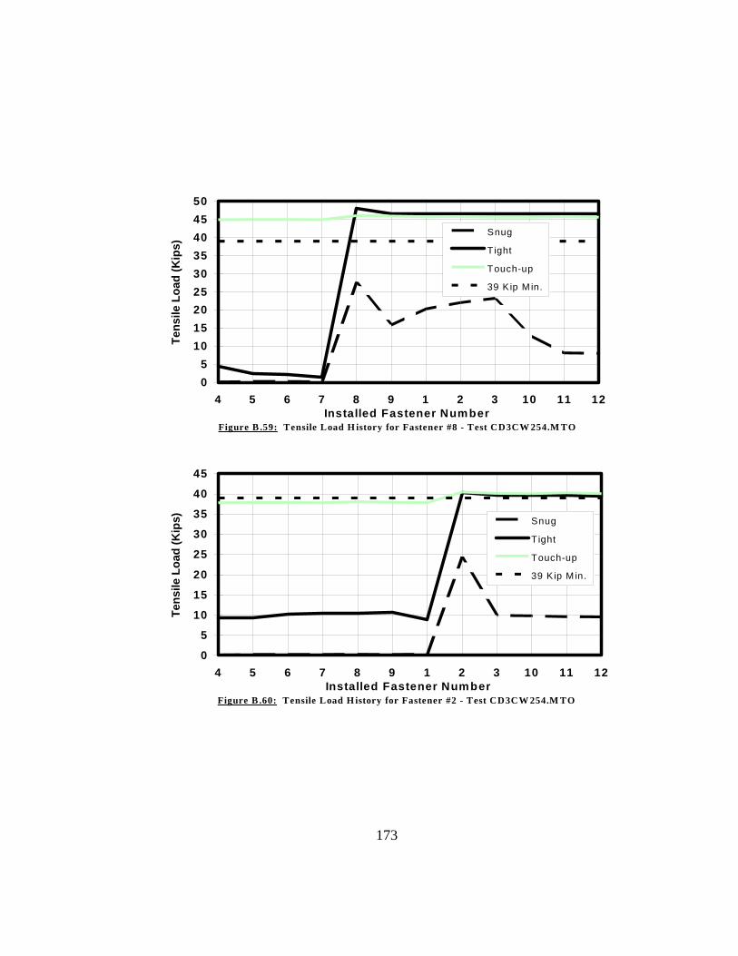
173
05
101520253035404550
4 5 6 7 8 9 1 2 3 10 11 1Installed Fastener Number
Tens
ile L
oad
(Kip
s)
2
Snug
Tight
Touch-up
39 Kip M in.
Figure B .59: Tensile Load H istory for Fastener #8 - Test CD3CW 254.M TO
0
5
10
15
20
25
30
35
40
45
4 5 6 7 8 9 1 2 3 10 11 1Installed Fastener Number
Tens
ile L
oad
(Kip
s)
2
Snug
Tight
Touch-up
39 Kip M in.
Figure B .60: Tensile Load H istory for Fastener #2 - Test CD3CW 254.M TO

174
Fastener Number1 2 3 4 5 6 7 8 9 10 11 12
1 11.1 0.0 0.0 0.0 0.0 0.0 0.0 0.0 0.0 0.0 0.3 0.52 6.0 12.1 0.0 0.0 -0.1 0.0 0.0 -0.1 0.0 0.0 0.4 0.53 5.8 7.8 12.0 0.0 0.0 0.0 0.0 0.0 0.0 0.0 0.5 0.34 6.3 7.3 11.4 13.1 0.0 0.0 0.0 0.0 0.0 0.0 0.1 0.55 6.4 7.9 10.0 9.0 12.0 0.0 0.0 0.0 0.0 0.0 0.0 0.26 6.5 8.2 9.5 9.3 7.8 13.5 0.1 0.1 0.0 0.0 0.0 0.07 6.4 8.3 9.4 6.8 6.5 12.5 8.9 0.0 0.0 0.0 0.0 0.08 6.3 8.2 9.4 6.5 4.2 10.2 5.2 13.8 -0.1 -0.1 -0.1 0.09 6.3 8.3 9.7 6.8 4.2 6.0 5.4 8.6 14.4 -0.1 0.0 0.010 6.4 8.4 9.7 7.6 4.7 6.4 4.5 7.3 13.3 13.6 0.0 0.011 6.4 8.3 9.7 7.5 4.8 6.6 4.6 7.5 12.7 13.5 14.2 0.012 6.4 8.3 9.7 7.5 4.8 6.7 4.6 7.6 12.5 13.3 14.1 11.61 41.2 8.1 9.2 7.5 4.5 6.4 4.3 7.3 12.5 12.5 13.3 10.62 40.8 43.6 9.5 7.6 4.8 6.5 4.3 7.3 12.5 12.5 13.3 10.63 40.5 42.8 39.0 7.6 4.9 6.9 4.4 7.4 12.6 12.6 13.3 10.64 40.6 42.8 38.5 42.2 4.0 6.9 2.8 6.7 12.7 12.6 13.3 10.65 40.6 42.9 38.5 41.8 39.8 6.5 2.9 5.5 12.5 12.7 13.4 10.76 40.6 42.9 38.4 41.7 39.5 40.9 2.9 5.6 11.6 12.6 13.4 10.77 40.5 42.9 38.3 41.4 39.3 40.6 34.5 5.0 11.6 13.0 13.4 10.68 40.5 42.8 38.2 41.4 39.2 40.4 33.8 42.0 11.3 12.9 13.7 10.69 40.4 42.8 38.2 41.3 39.2 40.4 33.7 41.5 43.0 12.9 13.7 10.910 40.4 42.7 38.1 41.3 39.1 40.3 33.6 41.3 42.5 41.2 13.8 10.911 40.5 42.8 38.1 41.3 39.1 40.3 33.6 41.3 42.3 40.8 38.8 11.212 40.4 42.7 38.0 41.2 39.1 40.2 33.5 41.2 42.2 40.6 38.4 41.51 40.3 42.4 37.8 40.9 38.7 39.9 33.1 40.7 41.6 39.9 37.7 40.32 40.2 43.7 37.8 40.9 38.7 39.9 33.1 40.7 41.6 39.9 37.7 40.33 40.2 43.6 39.9 43.6 41.2 39.9 33.1 40.7 41.6 39.9 37.7 40.24 40.2 43.6 39.8 43.5 41.1 43.0 33.1 40.7 41.6 39.9 37.7 40.25 40.1 43.5 39.8 43.5 41.1 42.9 33.1 40.7 41.6 39.9 37.7 40.26 40.2 43.5 39.8 43.4 41.0 42.9 33.1 40.7 41.6 39.9 37.7 40.27 40.2 43.5 39.7 43.4 41.0 42.9 34.5 40.7 41.6 39.9 37.7 40.28 40.1 43.5 39.7 43.4 41.0 42.9 34.4 42.7 44.8 39.9 37.7 40.29 40.2 43.5 39.7 43.4 41.0 42.9 34.4 42.7 44.7 39.9 37.7 40.210 40.1 43.5 39.7 43.4 40.9 42.8 34.3 42.6 44.6 42.6 37.7 40.211 40.2 43.5 39.7 43.4 40.9 42.8 34.3 42.6 44.6 42.5 41.5 43.312 40.2 43.5 39.7 43.4 40.9 42.8 34.3 42.6 44.6 42.4 41.4 43.2
Tension in KipsAverage Fastener Tension (after snugging) = 8.9 Kips(after tightening) = 39.9 Kips(after touch-up) = 41.6 Kips
3-1/4" Conventional Fasteners2" GripDeformed Plates (3mm gap)Cal. Wrench Installation (with 12 kip Snug)Tightened from Top Left to Bottom Right
Fastener Numbers
Snu
ggin
g O
rder
Tigh
teni
ng O
rder
Touc
h-up
Ord
er
Figure B.61: Fastener Tensions for test CD3CW122.LTR

175
0
5
10
15
20
25
30
35
40
45
1 2 3 4 5 6 7 8 9 10 11 12Fastener Number
Fina
l Ins
talle
d Te
nsio
n (K
ips)
39 Kips
Figure B.62: Final Installed Tensions for Test CD3CW122.LTR
0
5
10
15
20
25
30
35
40
45
1 2 3 4 5 6 7 8 9 10 11 1Installed Fastener Number
Tens
ile L
oad
(Kip
s)
2
Snug
Tight
Touch-up
39 Kip Min.
Figure B.63: Tensile Load History for Fastener #1 - Test CD3CW122.LTR

176
0
5
10
15
20
25
30
35
40
45
1 2 3 4 5 6 7 8 9 10 11 1Installed Fastener Number
Tens
ile L
oad
(Kip
s)
2
Snug
Tight
Touch-up
39 Kip Min.
Figure B.64: Tensile Load History for Fastener #5 - Test CD3CW122.LTR
0
5
10
15
20
25
30
35
40
1 2 3 4 5 6 7 8 9 10 11 1Installed Fastener Number
Tens
ile L
oad
(Kip
s)
2
Snug
Tight
Touch-up
39 Kip Min.
Figure B.65: Tensile Load History for Fastener #7 - Test CD3CW122.LTR

177
Fastener Number1 2 3 4 5 6 7 8 9 10 11 12
1 12.1 -0.1 -0.1 -0.1 -0.1 -0.1 -0.1 -0.1 -0.1 1.2 2.5 0.02 7.2 10.6 0.0 0.0 0.0 0.0 0.0 0.1 0.0 1.4 3.2 0.23 7.4 4.2 10.3 0.0 0.0 0.0 0.0 0.0 0.0 1.4 3.7 0.14 3.4 2.6 8.6 8.5 0.0 0.1 0.1 0.1 0.1 0.6 3.7 0.25 3.3 1.5 7.6 2.8 9.9 0.0 0.0 0.0 0.0 0.6 2.8 0.06 3.5 1.5 5.9 2.9 3.4 11.3 0.0 0.0 0.0 0.7 2.0 0.07 3.5 1.6 6.6 -0.1 0.7 9.4 12.1 -0.1 0.0 0.0 0.0 0.08 3.8 1.5 7.8 -0.1 0.0 4.9 5.5 10.7 0.0 0.0 -0.1 0.09 4.1 1.9 9.0 0.1 0.1 1.0 6.6 2.4 12.4 0.1 0.1 0.210 5.4 2.0 9.9 0.6 1.0 3.2 0.2 0.2 8.4 13.3 0.2 0.211 5.3 1.8 10.5 0.8 1.0 4.1 0.0 0.0 3.5 5.5 11.9 0.112 5.2 2.1 11.8 1.3 1.5 3.9 0.2 0.2 0.7 6.7 3.5 12.11 41.6 1.1 12.1 0.5 0.7 4.0 0.5 0.5 1.0 6.6 3.8 12.02 41.1 43.8 8.1 0.5 0.4 2.7 0.5 0.5 0.9 6.4 3.7 11.93 41.1 44.0 41.9 0.5 0.4 0.9 0.6 0.5 0.6 6.5 3.8 12.04 40.5 43.8 41.3 40.8 0.4 0.6 0.6 0.6 0.6 5.4 3.6 12.05 40.8 44.0 40.1 36.1 43.3 0.6 0.6 0.6 0.6 5.7 3.4 11.16 40.7 44.2 40.2 36.0 39.6 44.4 0.5 0.5 0.6 6.0 3.7 9.77 40.8 44.2 40.3 34.5 39.3 44.1 44.1 0.6 0.7 1.2 2.4 10.08 40.8 44.2 40.2 34.7 38.4 43.0 43.1 41.1 0.7 1.0 1.0 7.99 40.8 44.2 40.4 34.7 38.7 39.4 43.1 39.5 42.9 1.4 0.9 3.410 40.8 44.2 40.4 34.7 38.7 39.5 42.5 39.1 42.6 46.6 0.6 2.511 40.9 44.2 40.3 34.7 38.7 39.5 42.6 38.9 42.0 46.3 47.5 0.912 40.9 44.2 40.3 34.7 38.7 39.6 42.6 39.2 40.9 46.2 47.0 46.31 41.8 44.2 40.4 34.8 38.7 39.6 42.6 39.1 41.0 46.2 46.8 45.62 41.8 45.1 40.4 34.8 38.7 39.6 42.6 39.1 41.0 46.2 46.7 45.63 41.8 45.1 41.7 34.8 38.8 39.7 42.6 39.2 41.0 46.2 46.8 45.64 41.8 45.1 41.7 36.7 38.8 39.7 42.6 39.2 41.0 46.2 46.8 45.65 41.8 45.1 41.7 36.7 42.6 39.7 42.6 39.2 41.1 46.2 46.8 45.76 41.8 45.1 41.7 36.7 42.5 42.8 42.6 39.2 41.0 46.2 46.8 45.77 41.8 45.1 41.7 36.6 42.5 42.8 43.9 39.2 41.0 46.3 46.8 45.78 41.8 45.0 41.7 36.6 42.5 42.7 43.8 40.1 41.0 46.2 46.8 45.69 41.8 45.0 41.7 36.6 42.4 42.6 43.8 40.1 41.8 46.2 46.8 45.610 41.8 45.0 41.7 36.6 42.4 42.6 43.8 40.1 41.7 47.4 46.8 45.611 41.8 45.1 41.6 36.6 42.4 42.6 43.8 40.1 41.7 47.4 48.4 45.612 41.8 45.1 41.7 36.6 42.5 42.7 43.8 40.1 41.8 47.4 48.3 46.5
Tension in KipsAverage Fastener Tension (after snugging) = 4.1 Kips(after tightening) = 41.7 Kips(after 2nd tightening)= 43.2 Kips
4-1/4" Conventional Fasteners3" GripDeformed Plates (3mm gap)Cal. Wrench Installation (with 12 kip Snug)Tightened from Top Left to Bottom Right
Fastener Numbers
Snug
ging
Ti
ghte
ning
Ti
ghte
ning
Ord
er
Figure B.66: Fastener Tensions for test CD3CW123.LTR
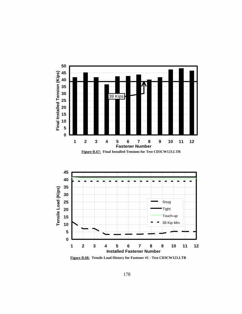
178
05
101520253035404550
1 2 3 4 5 6 7 8 9 10 11 12Fastener Number
Fina
l Ins
talle
d Te
nsio
n (K
ips)
39 Kips
Figure B.67: Final Installed Tensions for Test CD3CW123.LTR
0
510
1520
2530
3540
45
1 2 3 4 5 6 7 8 9 10 11 1Installed Fastener Number
Tens
ile L
oad
(Kip
s)
2
Snug
Tight
Touch-up
39 Kip Min.
Figure B.68: Tensile Load History for Fastener #1 - Test CD3CW123.LTR
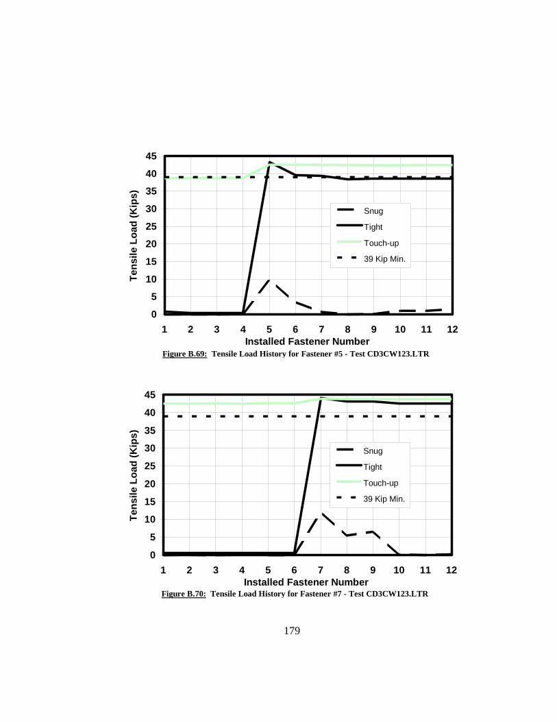
179
0
5
10
15
20
25
30
35
40
45
1 2 3 4 5 6 7 8 9 10 11 1Installed Fastener Number
Tens
ile L
oad
(Kip
s)
2
Snug
Tight
Touch-up
39 Kip Min.
Figure B.69: Tensile Load History for Fastener #5 - Test CD3CW123.LTR
0
5
10
15
20
25
30
35
40
45
1 2 3 4 5 6 7 8 9 10 11 1Installed Fastener Number
Tens
ile L
oad
(Kip
s)
2
Snug
Tight
Touch-up
39 Kip Min.
Figure B.70: Tensile Load History for Fastener #7 - Test CD3CW123.LTR

180
Fastener Number1 2 3 4 5 6 7 8 9 10 11 12
1 11.5 0.1 0.1 0.1 0.1 0.1 0.1 0.1 0.1 0.2 5.7 0.42 5.2 12.9 0.1 0.1 0.1 0.1 0.1 0.1 0.1 0.2 6.8 0.43 5.4 6.9 11.2 0.1 0.1 0.1 0.1 0.1 0.1 0.2 7.3 0.24 1.3 4.3 10.0 12.0 0.0 0.0 0.1 0.0 0.1 0.0 5.3 0.25 1.5 2.8 7.3 6.3 11.6 0.1 0.1 0.1 0.1 0.1 4.5 0.16 1.9 2.7 3.7 5.9 5.1 12.0 0.1 0.1 0.1 0.1 3.7 0.07 2.6 3.5 4.4 1.2 2.2 10.9 12.3 0.1 0.1 0.1 0.9 0.18 3.1 3.7 5.2 1.0 1.0 7.0 7.2 11.4 0.1 0.0 0.0 0.09 3.9 4.8 6.2 1.3 0.9 2.4 6.6 4.1 11.8 1.2 0.0 0.010 5.5 5.8 7.6 2.4 1.9 4.2 0.9 0.9 8.2 12.5 0.0 0.011 5.7 6.1 8.9 2.7 2.2 5.3 1.0 0.1 3.3 4.5 12.1 0.012 5.6 6.3 10.0 3.0 2.4 4.7 1.5 0.1 0.7 4.6 3.6 10.91 41.6 0.5 7.6 0.3 0.5 4.6 0.5 0.0 0.8 5.1 3.7 10.62 35.1 43.5 0.8 0.1 0.2 1.7 0.2 0.0 0.5 5.2 3.4 11.33 34.9 36.2 39.7 0.1 0.1 0.4 0.2 0.1 0.2 5.6 3.5 10.34 28.0 30.6 36.3 42.6 0.2 0.3 0.1 0.1 0.1 4.7 2.6 10.35 28.6 29.5 32.7 35.3 39.3 0.2 0.0 0.0 0.1 5.1 2.0 9.26 28.8 30.7 29.2 34.8 31.1 40.2 0.0 0.1 0.1 5.6 2.2 7.27 29.2 30.9 29.3 29.0 28.3 39.0 39.8 0.0 0.1 0.1 0.4 6.88 29.2 31.1 29.4 29.1 26.2 36.8 32.1 39.4 0.1 0.1 0.1 2.89 29.3 31.2 29.8 29.4 26.3 30.1 31.4 30.6 42.1 0.1 0.1 0.010 29.4 31.3 29.9 30.2 26.7 30.7 22.7 22.9 35.8 42.0 0.1 0.111 29.3 31.2 29.8 30.2 26.9 31.0 23.4 20.3 29.9 39.6 45.6 0.012 29.3 31.2 29.9 30.2 26.8 31.1 23.4 20.8 28.1 39.7 43.5 43.51 40.3 31.2 29.9 30.0 26.7 30.9 23.5 20.9 28.7 39.5 43.2 42.62 40.2 40.6 29.8 30.1 26.7 31.0 23.5 20.9 28.7 39.6 43.2 42.63 40.1 40.5 36.8 30.1 26.7 31.0 23.5 20.9 28.7 39.5 43.2 42.74 40.1 40.5 36.7 41.9 26.7 31.0 22.8 20.8 28.7 39.5 43.2 42.65 40.0 40.4 36.7 41.8 37.2 30.9 22.8 20.6 28.7 39.5 43.2 42.66 40.0 40.5 36.7 41.7 37.0 38.9 22.8 20.6 28.1 39.5 43.2 42.67 40.0 40.4 36.6 41.2 36.9 38.7 37.0 20.3 28.1 39.4 43.2 42.68 40.0 40.4 36.7 41.1 36.5 38.7 36.6 39.7 27.9 39.5 43.1 42.69 40.1 40.5 36.7 41.1 36.6 37.8 36.6 39.6 42.8 39.5 43.2 42.610 40.1 40.5 36.7 41.2 36.5 37.9 36.6 39.6 42.6 41.0 43.2 42.611 40.0 40.5 36.7 41.1 36.4 37.8 36.5 39.4 42.5 40.9 44.6 42.512 40.1 40.5 36.7 41.1 36.6 37.9 36.5 39.5 42.5 40.9 44.6 43.9
Tension in KipsAverage Fastener Tension (after snugging) = 4.5 Kips(after tightening) = 31.4 Kips(after touch-up) = 40.1 Kips
5-1/4" Conventional Fasteners4" GripDeformed Plates (3mm gap)Turn-of-Nut Installation (with 12 kip Snug)Tightened from Top Left to Bottom Right
Fastener Numbers
Snu
ggin
g O
rder
Tigh
teni
ng O
rder
Touc
h-up
Ord
er
Figure B.71: Fastener Tensions for test CD3CW124.LTR

181
0
5
10
15
20
25
30
35
40
45
1 2 3 4 5 6 7 8 9 10 11 12Fastener Number
Fina
l Ins
talle
d Te
nsio
n (K
ips)
39 Kips
Figure B.72: Tensile Load History for Fastener #1 - Test CD3CW124.LTR
0
510
1520
2530
3540
45
1 2 3 4 5 6 7 8 9 10 11 1Installed Fastener Number
Tens
ile L
oad
(Kip
s)
2
Snug
Tight
Touch-up
39 Kip Min.
Figure B.73: Tensile Load History for Fastener #1 - Test CD3CW124.LTR

182
0
5
10
15
20
25
30
35
40
1 2 3 4 5 6 7 8 9 10 11 1Installed Fastener Number
Tens
ile L
oad
(Kip
s)
2
Snug
Tight
Touch-up
39 Kip Min.
Figure B.74: Tensile Load History for Fastener #5 - Test CD3CW124.LTR
0
5
10
15
20
25
30
35
40
1 2 3 4 5 6 7 8 9 10 11 1Installed Fastener Number
Tens
ile L
oad
(Kip
s)
2
Snug
Tight
Touch-up
39 Kip Min.
Figure B.75: Tensile Load History for Fastener #7 - Test CD3CW124.LTR
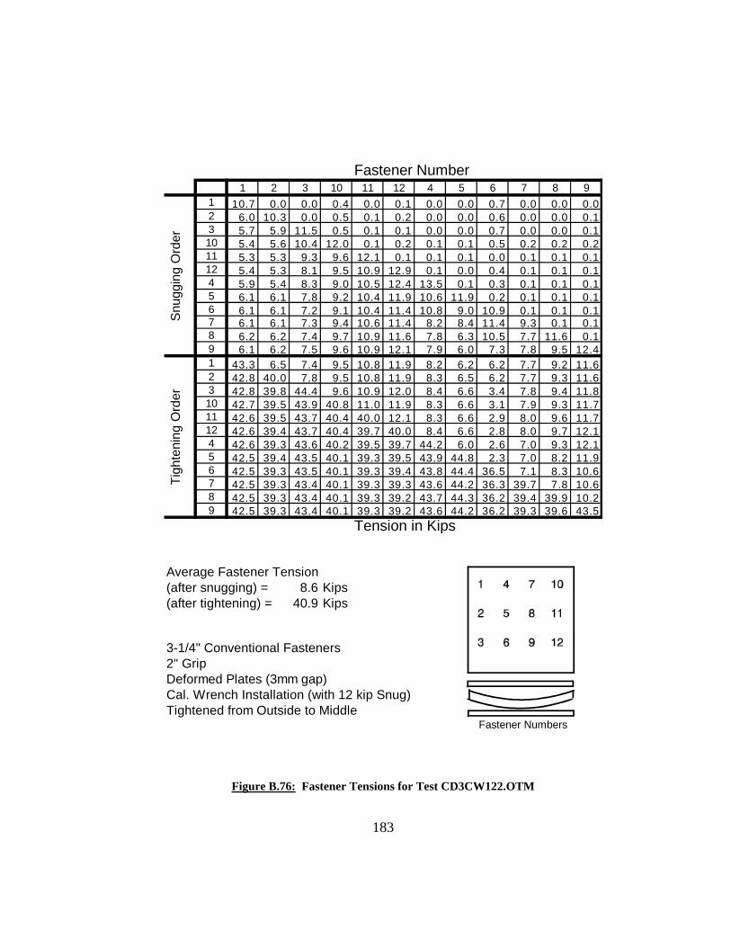
Fastener Number1 2 3 10 11 12 4 5 6 7 8 9
1 10.7 0.0 0.0 0.4 0.0 0.1 0.0 0.0 0.7 0.0 0.0 0.02 6.0 10.3 0.0 0.5 0.1 0.2 0.0 0.0 0.6 0.0 0.0 0.13 5.7 5.9 11.5 0.5 0.1 0.1 0.0 0.0 0.7 0.0 0.0 0.110 5.4 5.6 10.4 12.0 0.1 0.2 0.1 0.1 0.5 0.2 0.2 0.211 5.3 5.3 9.3 9.6 12.1 0.1 0.1 0.1 0.0 0.1 0.1 0.112 5.4 5.3 8.1 9.5 10.9 12.9 0.1 0.0 0.4 0.1 0.1 0.14 5.9 5.4 8.3 9.0 10.5 12.4 13.5 0.1 0.3 0.1 0.1 0.15 6.1 6.1 7.8 9.2 10.4 11.9 10.6 11.9 0.2 0.1 0.1 0.16 6.1 6.1 7.2 9.1 10.4 11.4 10.8 9.0 10.9 0.1 0.1 0.17 6.1 6.1 7.3 9.4 10.6 11.4 8.2 8.4 11.4 9.3 0.1 0.18 6.2 6.2 7.4 9.7 10.9 11.6 7.8 6.3 10.5 7.7 11.6 0.19 6.1 6.2 7.5 9.6 10.9 12.1 7.9 6.0 7.3 7.8 9.5 12.41 43.3 6.5 7.4 9.5 10.8 11.9 8.2 6.2 6.2 7.7 9.2 11.62 42.8 40.0 7.8 9.5 10.8 11.9 8.3 6.5 6.2 7.7 9.3 11.63 42.8 39.8 44.4 9.6 10.9 12.0 8.4 6.6 3.4 7.8 9.4 11.810 42.7 39.5 43.9 40.8 11.0 11.9 8.3 6.6 3.1 7.9 9.3 11.711 42.6 39.5 43.7 40.4 40.0 12.1 8.3 6.6 2.9 8.0 9.6 11.712 42.6 39.4 43.7 40.4 39.7 40.0 8.4 6.6 2.8 8.0 9.7 12.14 42.6 39.3 43.6 40.2 39.5 39.7 44.2 6.0 2.6 7.0 9.3 12.15 42.5 39.4 43.5 40.1 39.3 39.5 43.9 44.8 2.3 7.0 8.2 11.96 42.5 39.3 43.5 40.1 39.3 39.4 43.8 44.4 36.5 7.1 8.3 10.67 42.5 39.3 43.4 40.1 39.3 39.3 43.6 44.2 36.3 39.7 7.8 10.68 42.5 39.3 43.4 40.1 39.3 39.2 43.7 44.3 36.2 39.4 39.9 10.29 42.5 39.3 43.4 40.1 39.3 39.2 43.6 44.2 36.2 39.3 39.6 43.5
Tension in Kips
Average Fastener Tension (after snugging) = 8.6 Kips(after tightening) = 40.9 Kips
3-1/4" Conventional Fasteners2" GripDeformed Plates (3mm gap)Cal. Wrench Installation (with 12 kip Snug)Tightened from Outside to Middle
Fastener Numbers
Snu
ggin
g O
rder
Tigh
teni
ng O
rder
Figure B.76: Fastener Tensions for Test CD3CW122.OTM
183

05
1015202530354045
1 2 3 10 11 12 4 5 6 7 8 9Fastener Number
Fina
l Ins
talle
d Te
nsio
n (K
ips)
39 Kips
Figure B.77: Final Installed Tensions for Test CD3CW122.OTM
0
510
1520
2530
3540
45
1 2 3 10 11 12 4 5 6 7 8Installed Fastener Number
Tens
ile L
oad
(Kip
s)
9
Snug
Tight
39 Kip Min.
Figure B.78: Tensile Load History for Fastener #1 - Test CD3CW122.OTM
184

0
510
15
2025
30
3540
45
1 2 3 10 11 12 4 5 6 7 8Installed Fastener Number
Tens
ile L
oad
(Kip
s)
9
Snug
Tight
39 Kip Min.
Figure B.79: Tensile Load History for Fastener #10 - Test CD3CW122.OTM
0
510
1520
2530
3540
45
1 2 3 10 11 12 4 5 6 7 8 9Installed Fastener Number
Tens
ile L
oad
(Kip
s)
Snug
Tight
39 Kip Min.
Figure B.80: Tensile Load History for Fastener #5 - Test CD3CW122.OTM
185

Fastener Number1 2 3 10 11 12 4 5 6 7 8 9
1 11.4 0.0 0.0 1.3 0.0 0.8 0.0 0.0 0.0 0.0 0.0 0.02 7.7 12.5 0.0 1.6 0.1 1.2 0.1 0.0 0.1 0.0 0.0 0.03 7.4 8.6 13.0 1.7 0.2 1.4 0.0 0.0 0.0 0.0 0.0 0.110 6.9 6.7 12.3 9.5 0.0 0.0 0.0 0.0 0.0 0.0 0.0 0.011 7.0 5.7 11.8 2.5 11.1 0.0 0.0 0.0 0.0 0.0 0.0 0.112 7.0 5.1 11.6 3.9 0.9 12.0 0.0 0.0 0.0 0.0 0.0 0.04 3.7 3.6 11.1 2.8 0.8 11.4 11.5 0.0 0.1 0.0 0.0 0.05 4.2 2.8 9.8 2.8 0.8 10.6 7.0 11.7 0.1 0.1 0.1 0.16 4.3 3.3 7.4 2.8 0.9 9.4 7.1 6.4 11.3 0.0 0.1 0.17 5.0 3.2 7.5 0.3 0.5 9.3 3.8 4.6 10.8 12.6 0.0 0.18 5.1 3.3 7.7 0.2 0.2 7.8 3.5 2.7 8.6 9.8 13.1 0.19 5.0 3.4 8.0 0.4 0.3 5.3 3.6 2.4 4.4 10.1 9.9 12.31 39.6 3.0 8.8 0.0 0.3 5.4 3.3 2.9 4.7 10.2 9.8 11.82 39.6 41.6 6.6 0.0 0.3 5.4 3.5 2.4 4.8 10.2 9.9 11.83 39.5 41.7 45.3 0.0 0.2 5.6 3.5 2.7 3.4 10.3 9.9 12.010 39.4 41.6 44.9 34.4 0.0 2.5 4.7 3.4 3.8 4.2 6.8 12.311 39.3 41.5 44.6 33.8 42.7 0.1 4.8 3.7 4.6 4.7 5.5 10.912 39.3 41.4 44.6 33.7 42.1 45.0 4.7 3.8 4.7 4.7 6.2 7.24 39.5 41.5 44.5 33.8 42.0 44.8 38.4 2.2 4.6 1.9 4.8 7.35 39.6 41.5 44.6 33.8 42.1 44.7 36.7 41.1 2.5 1.8 2.7 5.96 39.6 41.6 44.8 33.8 42.1 44.5 36.7 39.9 37.7 1.8 2.4 3.07 39.6 41.7 44.8 34.0 42.3 44.6 35.6 39.7 37.6 41.7 2.1 3.08 39.5 41.6 44.8 34.0 42.3 44.5 35.6 38.6 36.9 41.5 42.4 2.49 39.5 41.6 44.8 34.0 42.4 44.6 35.6 38.6 33.1 41.4 41.8 41.4
Tension in Kips
Average Fastener Tension (after snugging) = 5.4 Kips(after tightening) = 39.9 Kips
4-1/4" Conventional Fasteners3" GripDeformed Plates (3mm gap)Cal. Wrench Installation (with 12 kip Snug)Tightened from Outside to Middle
Fastener Numbers
Snu
ggin
g O
rder
Tigh
teni
ng O
rder
Figure B.81: Fastener Tensions for Test CD3CW123.OTM
186
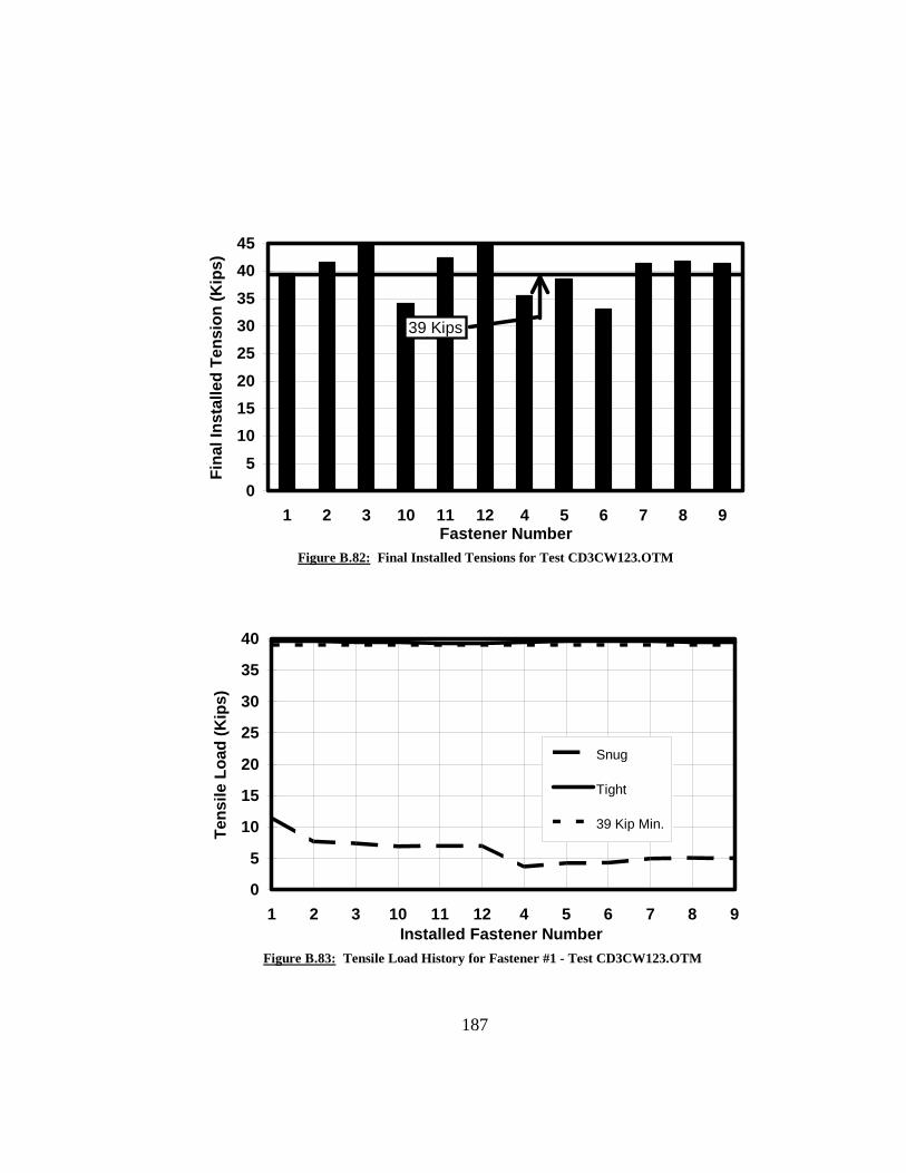
05
1015202530354045
1 2 3 10 11 12 4 5 6 7 8 9Fastener Number
Fina
l Ins
talle
d Te
nsio
n (K
ips)
39 Kips
Figure B.82: Final Installed Tensions for Test CD3CW123.OTM
0
5
10
15
20
25
30
35
40
1 2 3 10 11 12 4 5 6 7 8Installed Fastener Number
Tens
ile L
oad
(Kip
s)
9
Snug
Tight
39 Kip Min.
Figure B.83: Tensile Load History for Fastener #1 - Test CD3CW123.OTM
187

0
5
10
15
20
25
30
35
40
1 2 3 10 11 12 4 5 6 7 8Installed Fastener Number
Tens
ile L
oad
(Kip
s)
9
Snug
Tight
39 Kip Min.
Figure B.84: Tensile Load History for Fastener #10 - Test CD3CW123.OTM
0
510
15
2025
30
3540
45
1 2 3 10 11 12 4 5 6 7 8Installed Fastener Number
Tens
ile L
oad
(Kip
s)
9
Snug
Tight
39 Kip Min.
Figure B.85: Tensile Load History for Fastener #5 - Test CD3CW123.OTM
188

Fastener Number1 2 3 10 11 12 4 5 6 7 8 9
1 11.0 0.0 0.0 2.8 0.5 2.7 -0.1 0.0 0.0 0.0 0.0 0.02 4.6 12.2 0.0 3.2 0.9 3.4 0.0 0.0 0.0 0.0 0.0 0.03 4.7 5.0 13.8 3.5 1.2 3.2 0.0 0.0 0.0 0.0 0.0 0.010 4.5 5.0 14.0 11.5 0.0 0.0 -0.1 0.0 0.0 0.0 0.0 0.011 5.1 5.0 13.6 3.3 11.6 0.0 -0.1 0.0 0.0 0.0 0.0 0.012 5.4 5.5 13.4 3.6 1.5 12.4 0.0 0.0 0.0 0.0 0.0 0.04 1.6 3.8 12.7 2.4 1.1 11.7 12.1 0.0 0.0 0.0 0.0 0.05 1.8 2.6 10.1 2.4 0.9 10.6 6.0 12.4 0.0 0.0 0.0 0.06 2.3 2.7 6.0 2.6 1.0 9.1 5.6 5.7 12.7 0.0 0.0 0.07 2.9 3.5 6.8 0.3 0.2 8.7 1.6 3.1 11.3 12.6 0.0 0.08 3.2 3.6 7.6 0.1 0.0 6.7 1.1 1.6 8.0 8.0 11.8 0.09 3.4 4.2 8.1 0.3 0.0 3.3 1.1 1.0 2.6 8.2 6.4 14.21 38.5 0.2 5.5 0.9 0.0 3.9 0.0 0.1 2.2 6.7 5.3 13.82 34.6 43.9 0.4 1.0 0.0 4.6 -0.1 0.0 0.6 6.0 4.1 13.13 34.7 40.0 45.1 1.2 0.1 5.6 0.0 0.0 0.1 6.0 3.9 8.810 34.0 39.9 45.6 46.2 0.0 -0.1 -0.1 0.0 0.1 0.0 0.0 4.811 33.5 39.1 44.8 37.5 41.4 -0.2 -0.2 -0.1 -0.1 -0.1 -0.2 0.212 33.4 38.8 42.9 37.9 34.1 41.0 -0.3 -0.2 -0.2 -0.2 -0.2 -0.34 31.3 37.8 42.8 36.2 33.4 40.5 42.6 -0.2 -0.2 -0.2 -0.2 -0.25 31.8 37.7 41.5 36.0 33.2 39.6 38.3 39.9 -0.3 -0.2 -0.3 -0.36 31.9 38.4 40.0 36.1 33.3 38.4 38.3 34.9 41.3 -0.2 -0.3 -0.37 32.1 38.5 40.1 35.5 33.5 38.5 33.8 33.5 40.9 44.1 -0.2 -0.28 32.1 38.5 40.1 35.8 33.4 38.3 33.6 31.5 39.3 41.4 42.6 -0.39 32.0 38.5 40.2 35.7 33.6 37.9 33.6 31.3 34.3 41.4 40.7 44.3
Tension in Kips
Average Fastener Tension (after snugging) = 4.4 Kips(after tightening) = 37.0 Kips
5-1/4" Conventional Fasteners4" GripDeformed Plates (3mm gap)Cal. Wrench Installation (with 12 kip Snug)Tightened from Outside to Middle
Fastener Numbers
Snu
ggin
g O
rder
Tigh
teni
ng O
rder
Figure B.86: Fastener Tensions for Test CD3CW124.OTM
189

0
5
10
15
20
25
30
35
40
45
1 2 3 10 11 12 4 5 6 7 8 9Fastener Number
Fina
l Ins
talle
d Te
nsio
n (K
ips)
39 Kips
Figure B.87: Final Installed Tensions for Test CD3CW124.OTM
0
5
10
15
20
25
30
35
40
1 2 3 10 11 12 4 5 6 7 8 9Installed Fastener Number
Tens
ile L
oad
(Kip
s)
Snug
Tight
39 Kip Min.
Figure B.88: Tensile Load History for Fastener #1 - Test CD3CW124.OTM
190
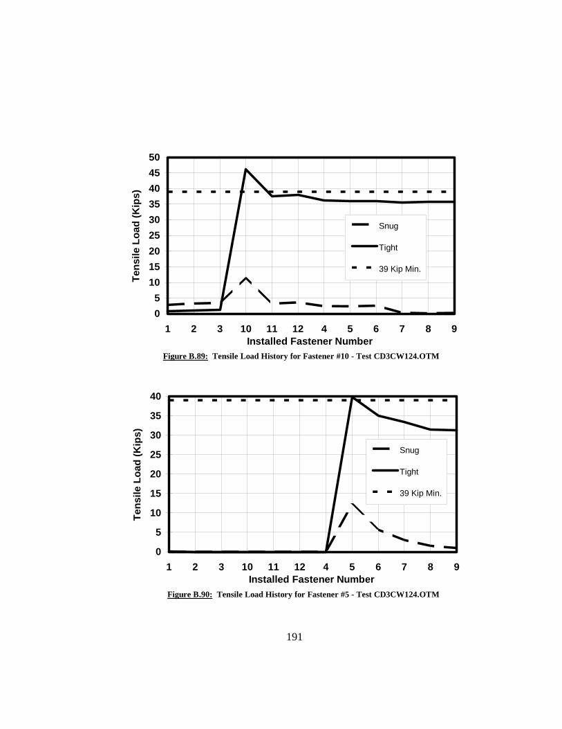
05
101520253035404550
1 2 3 10 11 12 4 5 6 7 8 9Installed Fastener Number
Tens
ile L
oad
(Kip
s)
Snug
Tight
39 Kip Min.
Figure B.89: Tensile Load History for Fastener #10 - Test CD3CW124.OTM
0
5
10
15
20
25
30
35
40
1 2 3 10 11 12 4 5 6 7 8 9Installed Fastener Number
Tens
ile L
oad
(Kip
s)
Snug
Tight
39 Kip Min.
Figure B.90: Tensile Load History for Fastener #5 - Test CD3CW124.OTM
191

Fastener Number4 5 6 7 8 9 1 2 3 10 11 12
4 13.3 0.0 0.0 0.1 -0.1 0.2 0.1 0.1 0.1 0.0 0.5 0.45 3.9 10.9 0.1 0.2 0.0 0.2 0.1 0.1 0.0 -0.1 0.6 0.26 4.8 2.1 10.1 0.1 0.0 0.0 0.1 0.0 0.0 0.0 0.8 0.17 3.7 1.2 10.5 9.6 0.0 0.1 0.1 0.1 0.0 0.0 0.0 0.18 4.3 0.6 9.6 5.2 8.0 0.2 0.1 0.1 0.0 -0.1 0.0 0.19 4.9 0.9 6.6 4.7 3.0 14.1 0.2 0.1 0.1 -0.1 0.1 0.11 0.6 0.0 3.7 5.9 3.4 14.1 11.0 0.1 0.0 0.0 0.0 0.12 0.7 -0.1 1.3 5.6 3.4 14.5 5.4 12.8 0.0 -0.1 0.0 0.13 0.7 0.1 0.9 5.7 3.5 14.7 5.4 10.2 9.1 0.0 0.0 0.110 1.2 0.1 1.4 2.9 2.0 12.1 5.3 10.2 8.7 14.3 0.1 0.211 1.3 0.1 1.7 2.9 1.7 9.0 5.2 10.2 8.7 9.4 12.9 0.112 1.3 0.1 1.7 2.7 2.0 7.3 5.3 10.2 8.6 9.2 11.0 11.84 24.4 0.0 1.7 1.2 0.6 7.3 6.2 10.5 8.5 9.4 10.9 11.15 21.1 22.8 1.1 0.9 -0.2 5.7 6.3 11.4 8.7 9.5 11.0 11.26 21.0 21.1 43.5 1.0 -0.3 2.6 6.3 11.4 9.4 9.4 11.1 11.27 18.2 20.1 43.0 16.4 -0.2 2.8 6.3 11.3 9.3 8.9 11.1 11.28 18.0 18.3 42.6 14.6 19.4 2.3 6.3 11.3 9.3 8.8 11.6 11.39 18.1 18.5 42.1 14.5 17.9 47.6 6.2 11.3 9.4 8.8 11.7 12.01 18.1 18.3 42.0 14.5 17.7 47.0 54.0 11.4 9.4 8.7 11.7 12.02 18.0 18.6 42.0 14.6 17.7 46.9 53.4 55.7 9.8 8.7 11.7 11.93 18.0 18.5 42.0 14.6 17.7 46.7 53.2 54.9 56.9 8.6 11.7 11.910 18.1 18.6 42.0 14.5 17.6 46.6 53.1 54.8 56.3 54.8 11.9 11.911 18.0 18.4 42.0 14.5 17.7 46.5 53.1 54.6 56.2 54.1 53.6 12.112 18.0 18.4 41.9 14.4 17.8 46.3 52.9 54.5 56.1 54.0 52.9 54.8
Tension in Kips
Average Fastener Tension (after snugging) = 5.9 Kips(after tightening) = 40.2 Kips
3-1/4" Conventional Fasteners2" GripDeformed Plates (6mm gap)Turn-of-Nut Installation (with 12 kip Snug)Tightened from Middle to Outside
Fastener Numbers
Snu
ggin
g O
rder
Tigh
teni
ng O
rder
Figure B.91: Fastener Tensions for Test CD6TN122.MTO
192
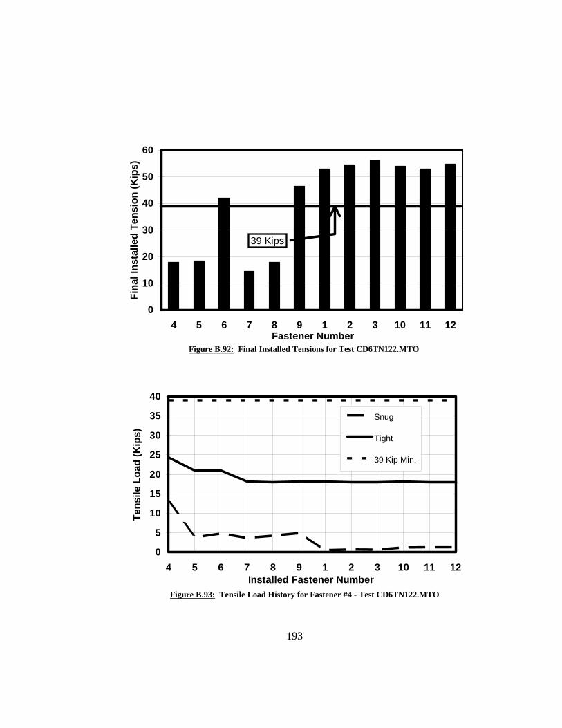
0
10
20
30
40
50
60
4 5 6 7 8 9 1 2 3 10 11 12Fastener Number
Fina
l Ins
talle
d Te
nsio
n (K
ips)
39 Kips
Figure B.92: Final Installed Tensions for Test CD6TN122.MTO
0
5
10
15
20
25
30
35
40
4 5 6 7 8 9 1 2 3 10 11 1Installed Fastener Number
Tens
ile L
oad
(Kip
s)
2
Snug
Tight
39 Kip Min.
Figure B.93: Tensile Load History for Fastener #4 - Test CD6TN122.MTO
193

0
5
10
15
20
25
30
35
40
4 5 6 7 8 9 1 2 3 10 11 1Installed Fastener Number
Tens
ile L
oad
(Kip
s)
2
Snug
Tight
39 Kip Min.
Figure B.94: Tensile Load History for Fastener #8 - Test CD6TN122.MTO
0
10
20
30
40
50
60
4 5 6 7 8 9 1 2 3 10 11 1Installed Fastener Number
Tens
ile L
oad
(Kip
s)
2
Snug
Tight
39 Kip Min.
Figure B.95: Tensile Load History for Fastener #2 - Test CD6TN122.MTO
194

Fastener Number4 5 6 7 8 9 1 2 3 10 11 12
4 12.3 -0.1 0.0 0.0 0.0 -0.1 0.0 -0.2 -0.4 0.3 0.2 0.85 4.5 12.5 0.0 0.0 0.0 0.0 0.0 -0.1 -0.2 0.7 0.1 0.66 5.2 5.0 9.3 -0.1 0.0 -0.1 -0.1 -0.1 -0.4 1.0 0.1 0.47 0.6 2.1 9.0 11.8 -0.1 -0.1 0.1 -0.1 -0.3 -0.1 -0.2 0.08 1.6 1.7 6.6 3.7 12.6 0.0 0.1 -0.1 -0.4 -0.2 -0.2 0.09 2.5 2.8 3.3 3.9 3.8 11.6 0.0 -0.1 -0.3 -0.2 -0.3 -0.11 0.0 0.1 -0.1 4.8 4.6 13.3 10.8 -0.2 -0.4 -0.2 -0.2 -0.12 0.1 0.0 -0.1 5.2 4.7 12.8 2.7 10.8 -0.3 -0.1 -0.1 0.13 0.1 0.0 0.0 5.4 5.2 12.1 3.2 2.0 9.8 -0.1 -0.2 0.210 0.0 0.3 -0.1 0.3 2.4 11.4 5.3 3.0 10.8 9.0 -0.4 0.011 0.0 0.4 0.0 1.0 0.8 7.2 5.8 3.0 12.2 3.9 10.7 0.012 0.1 0.4 -0.1 1.7 1.3 2.5 5.6 3.0 12.9 4.7 2.1 11.84 15.0 -0.1 -0.1 -0.2 -0.2 0.8 0.4 1.8 12.9 3.3 1.4 11.65 10.4 8.6 -0.2 -0.4 -0.2 -0.2 0.5 1.2 11.3 3.2 1.1 11.26 9.0 1.6 17.9 -0.2 -0.2 -0.2 1.1 1.4 4.2 3.3 1.4 8.17 0.0 0.5 14.2 15.5 -0.2 -0.3 1.6 1.9 5.2 0.3 -0.2 8.58 -0.1 0.1 4.7 2.3 25.8 -0.1 1.3 2.1 6.2 0.5 -0.6 4.09 0.0 0.1 0.4 3.6 11.6 19.0 1.7 2.5 5.5 1.3 -0.5 0.81 -0.1 -0.2 0.3 2.6 10.8 18.9 12.7 -0.2 3.3 2.3 -0.2 1.02 -0.2 -0.4 0.0 2.8 10.1 18.3 4.3 14.6 -1.1 2.4 -0.3 1.23 -0.1 -0.1 -0.2 2.9 10.2 16.6 5.1 3.2 12.5 2.4 -0.2 2.310 0.0 0.0 -0.1 0.3 8.1 17.5 5.6 3.5 12.3 9.2 -0.8 1.111 0.0 0.0 -0.1 0.7 5.7 15.2 5.9 3.4 12.8 4.6 10.3 -0.312 0.0 0.0 -0.2 1.1 7.2 8.5 5.9 3.5 13.3 5.4 0.6 13.74 20.7 -0.1 -0.2 -0.3 1.0 7.5 0.2 2.2 13.0 4.2 0.8 13.65 12.6 25.0 -0.3 -0.3 -0.2 2.9 0.6 1.2 10.3 4.4 0.7 13.86 13.2 16.0 24.9 -0.4 -0.3 -0.3 0.9 1.6 4.8 4.4 1.3 12.47 6.4 13.0 23.8 38.5 -0.2 -0.3 2.0 2.3 5.2 -0.4 -0.6 12.98 6.5 9.6 20.2 29.8 52.2 -0.4 2.2 2.5 5.7 -0.7 -0.8 7.29 6.7 10.6 13.1 29.9 46.0 50.0 2.3 2.7 7.1 -0.6 -0.8 0.81 3.7 9.6 13.5 29.7 45.7 48.9 40.9 -0.1 5.4 -0.6 -0.7 0.72 4.1 9.4 12.7 29.8 45.5 48.9 40.7 43.4 1.1 -0.6 -0.6 0.83 4.1 10.0 11.9 29.8 45.5 49.0 40.6 44.0 48.9 -0.6 -0.6 0.810 4.7 10.1 11.9 20.2 41.0 47.4 40.4 43.8 48.3 7.0 -1.0 0.111 4.7 10.3 12.4 20.3 38.9 43.7 40.6 43.8 48.2 3.5 9.3 -0.312 4.7 10.2 12.7 20.7 38.9 37.8 40.4 43.7 48.0 3.5 0.9 18.0
Tension in KipsAverage Fastener Tension (after snugging) = 3.8 Kips(after 1st 1/2 turn) = 4.9 Kips(after 2d 1/2 turn) = 23.3 Kips
4-1/4" Conventional Fasteners3" GripDeformed Plates (6mm gap)Turn-of-Nut Installation (with 12 kip Snug)Tightened from Middle to Outside
Fastener Numbers
Snu
ggin
g S
nugg
ing
Ord
er1s
t Tig
hten
ing
Ord
er2d
Tig
hten
ing
Ord
er
Figure B.96: Fastener Tensions for Test CD6TN123.MTO
195

05
101520253035404550
4 5 6 7 8 9 1 2 3 10 11 12Fastener Number
Fina
l Ins
talle
d Te
nsio
n (K
ips)
39 Kips
Figure B.97: Final Installed Tensions for Test CD6TN123.MTO
0
5
10
15
20
25
30
35
40
4 5 6 7 8 9 1 2 3 10 11 1Installed Fastener Number
Tens
ile L
oad
(Kip
s)
2
Snug
1st Tight
2d Tight
39 Kip Min.
Figure B.98: Tensile Load History for Fastener #4 - Test CD6TN123.MTO
196

0
10
20
30
40
50
60
4 5 6 7 8 9 1 2 3 10 11 1Installed Fastener Number
Tens
ile L
oad
(Kip
s)
2
Snug
1st Tight
2d Tight
39 Kip Min.
Figure B.99: Tensile Load History for Fastener #8 - Test CD6TN123.MTO
0
5
10
15
20
25
30
35
40
45
4 5 6 7 8 9 1 2 3 10 11 1Installed Fastener Number
Tens
ile L
oad
(Kip
s)
2
Snug
1st Tight
2d Tight
39 Kip Min.
Figure B.100: Tensile Load History for Fastener #2 - Test CD6TN123.MTO
197

Fastener Number4 5 6 7 8 9 1 2 3 10 11 12
4 29.3 -0.1 -0.1 0.0 0.0 0.0 -0.1 0.0 -0.1 2.1 1.2 0.95 10.3 28.8 -0.2 0.0 0.0 0.0 -0.2 -0.1 -0.1 2.6 0.9 1.16 11.2 7.7 27.0 0.1 0.1 0.1 -0.2 -0.1 -0.1 2.7 0.8 1.47 1.6 4.6 26.2 23.3 0.0 0.0 -0.1 0.0 0.0 -0.2 0.0 -0.38 2.8 3.2 19.6 7.6 26.9 0.0 -0.1 -0.1 0.0 -0.1 0.1 -0.59 5.4 4.8 9.2 6.4 8.3 27.1 -0.2 -0.1 -0.1 -0.2 0.0 -0.51 0.0 -0.4 0.5 10.0 10.6 31.6 22.4 -0.1 -0.1 -0.1 0.0 -0.52 0.0 -0.6 0.0 11.8 10.4 30.9 5.1 23.3 -0.1 0.1 0.0 -0.43 0.0 -0.6 0.3 12.6 11.1 28.6 4.8 2.9 28.1 0.3 -0.1 0.310 0.0 -0.5 0.7 1.4 5.3 24.9 7.7 4.2 28.9 16.7 0.0 -0.511 -0.1 -0.4 0.8 3.0 1.7 14.9 8.3 4.4 30.1 2.2 26.3 -0.512 0.0 -0.7 0.9 5.4 2.7 4.4 8.1 4.7 30.4 2.7 4.1 27.94 6.6 -1.3 1.1 4.6 4.8 7.5 7.2 6.9 41.4 3.4 5.2 26.35 5.4 3.0 1.0 4.2 4.2 6.7 7.2 6.2 40.7 3.4 5.2 26.46 5.2 2.2 8.4 4.1 3.7 4.4 7.3 6.0 38.7 3.6 5.3 26.37 1.7 1.0 8.0 15.5 1.7 4.1 7.3 6.1 38.8 1.5 4.3 26.88 1.1 0.1 6.3 11.0 16.1 2.2 7.3 5.6 38.4 1.4 2.8 25.69 1.1 -0.2 3.5 11.0 11.3 16.9 7.5 5.7 36.6 1.7 3.0 22.01 0.3 -0.5 3.7 10.4 11.0 16.7 16.8 3.4 36.4 1.9 3.3 22.12 0.2 -0.7 3.3 10.0 10.1 16.3 15.1 23.9 35.1 1.9 3.3 22.13 0.2 -0.8 2.5 10.0 9.8 14.7 15.0 22.9 52.9 1.9 3.3 22.110 0.3 -0.5 2.7 7.2 9.0 15.2 15.2 22.9 52.6 8.1 1.5 21.211 0.4 -0.5 2.8 7.0 6.8 14.8 15.2 23.0 52.6 4.2 14.0 15.312 0.4 -0.5 3.1 8.0 7.0 10.2 15.2 23.1 52.7 4.0 5.8 27.74 41.4 -1.5 2.2 0.4 2.8 8.9 9.5 19.0 52.1 3.9 5.7 27.35 34.1 34.5 1.2 0.3 1.0 5.2 10.1 18.1 50.6 4.1 5.4 27.56 33.8 26.2 49.3 0.3 0.8 0.5 10.1 19.2 48.7 4.2 5.7 26.87 25.8 23.4 48.5 40.5 0.0 0.6 10.7 19.5 48.9 0.3 2.8 27.18 25.5 20.6 46.4 32.0 49.9 0.0 10.8 19.6 48.9 0.0 0.7 21.79 25.7 20.4 38.6 32.0 43.9 55.0 10.8 19.8 49.2 0.0 0.5 12.41 25.8 20.6 38.7 32.0 43.7 54.3 54.2 19.7 49.3 0.0 0.5 12.62 25.9 20.6 38.8 31.9 43.8 54.0 53.9 57.2 49.2 0.0 0.5 12.53 25.9 20.6 38.7 31.9 43.6 53.9 53.9 56.8 52.8 0.1 0.5 12.510 26.5 20.8 38.9 19.9 38.1 53.2 53.8 56.8 52.7 13.6 -0.1 8.211 26.7 20.8 39.2 19.3 33.3 50.3 54.0 56.9 52.8 5.6 26.5 1.312 26.7 20.7 39.1 20.1 33.8 48.3 53.9 56.9 52.8 5.3 12.8 54.4
Tension in KipsAverage Fastener Tension (after snugging 25 kips) = 7.5 Kips(after 2 x1/6 turn for vis. snug) = 13.0 Kips(after tightening 1/2 turn) = 35.4 Kips
5-1/4" Conventional Fasteners4" GripDeformed Plates (6mm gap)Turn-of-Nut Installation (w/ 25 kip Snug then 1/3 turn total for visual plate contact)Tightened from Middle to Outside Fastener Numbers
Snu
ggin
g 25
K S
nug
Ord
erV
isua
l Snu
g O
rder
Tigh
teni
ng O
rder
Figure B.101: Fastener Tensions for Test CD6TN254.MTO
198

0
10
20
30
40
50
60
4 5 6 7 8 9 1 2 3 10 11 12Fastener Number
Fina
l Ins
talle
d Te
nsio
n (K
ips)
39 Kips
Figure B.102: Final Installed Tensions for Test CD6TN254.MTO
0
510
1520
2530
3540
45
4 5 6 7 8 9 1 2 3 10 11 1Installed Fastener Number
Tens
ile L
oad
(Kip
s)
2
25k Snug
Visual Snug
Tight
39 Kip Min.
Figure B.103: Tensile Load History for Fastener #4 - Test CD6TN254.MTO
199
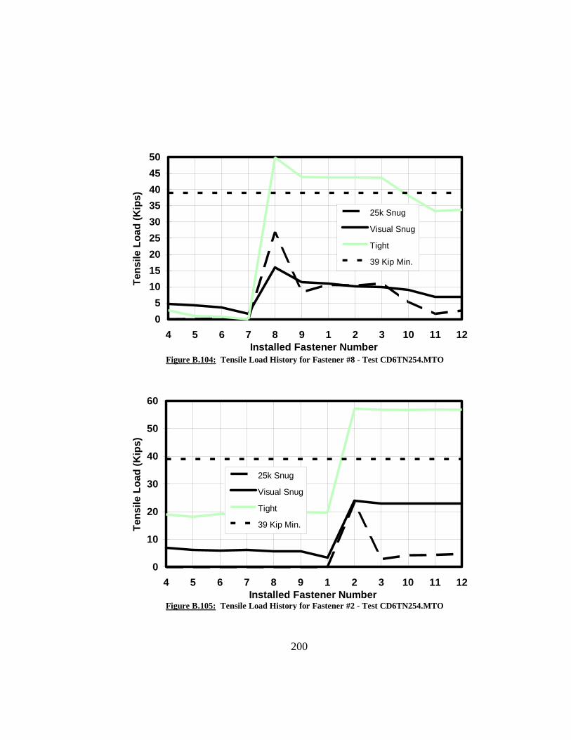
05
101520253035404550
4 5 6 7 8 9 1 2 3 10 11 1Installed Fastener Number
Tens
ile L
oad
(Kip
s)
2
25k Snug
Visual Snug
Tight
39 Kip Min.
Figure B.104: Tensile Load History for Fastener #8 - Test CD6TN254.MTO
0
10
20
30
40
50
60
4 5 6 7 8 9 1 2 3 10 11 1Installed Fastener Number
Tens
ile L
oad
(Kip
s)
2
25k Snug
Visual Snug
Tight
39 Kip Min.
Figure B.105: Tensile Load History for Fastener #2 - Test CD6TN254.MTO
200

Fastener Number4 5 6 7 8 9 1 2 3 10 11 12
4 12.3 -0.1 0.0 -0.1 0.0 0.0 0.0 0.0 -0.1 0.0 1.2 0.05 5.7 11.2 0.2 -0.2 -0.1 -0.2 -0.1 -0.1 -0.1 0.0 1.1 0.16 6.1 3.0 12.0 -0.1 0.0 0.0 0.0 0.0 -0.1 -0.1 1.2 0.17 0.7 0.9 10.1 10.3 -0.1 -0.1 -0.1 0.0 0.0 -0.1 -0.3 0.08 1.5 0.6 6.4 2.9 12.5 -0.1 -0.1 0.0 -0.1 -0.1 -0.3 0.09 2.8 1.3 2.8 3.1 3.0 11.5 -0.1 0.0 -0.1 -0.1 -0.3 0.01 -0.1 0.0 -0.1 4.3 4.7 12.4 9.6 0.0 -0.1 -0.1 -0.3 0.12 -0.1 0.1 0.0 4.8 5.3 11.3 1.7 11.2 -0.1 -0.1 -0.3 0.03 -0.1 -0.1 -0.1 4.8 6.2 10.2 1.8 1.5 11.1 0.0 -0.3 0.210 0.0 0.1 -0.1 0.0 0.9 9.8 3.1 2.3 12.0 10.3 -0.4 -0.111 -0.1 0.1 -0.1 0.7 0.3 7.2 3.2 2.4 12.9 3.5 8.3 0.012 -0.1 0.0 -0.1 1.4 0.5 2.9 3.2 2.5 13.9 4.2 0.7 11.64 38.5 -0.3 -0.3 -0.7 -0.4 -0.4 -0.3 -0.2 8.4 1.8 0.2 10.25 22.4 42.3 -0.1 -0.7 -0.3 -0.3 -0.2 -0.2 2.3 2.0 0.2 7.56 23.4 25.0 41.3 -0.6 -0.3 -0.3 -0.3 -0.4 -0.6 2.3 0.6 6.27 22.5 24.2 39.4 43.7 -0.3 -0.5 -0.1 -0.4 0.1 -0.3 -1.1 5.58 23.3 22.7 36.1 33.2 42.5 -0.4 0.1 -0.2 1.2 -0.4 -1.0 1.29 23.4 24.1 30.9 32.0 29.4 43.7 0.0 0.1 2.5 -0.4 -0.8 -0.41 10.3 16.0 27.8 32.0 29.0 42.7 41.3 -0.4 -0.6 -0.4 -0.8 -0.42 10.9 14.9 21.4 31.9 28.9 43.3 36.9 40.8 -0.6 -0.4 -0.8 -0.43 10.8 15.8 19.5 31.9 28.9 43.6 37.2 37.3 40.3 -0.3 -0.7 -0.410 11.5 16.2 20.0 18.5 16.8 36.0 37.2 37.2 39.6 44.1 -0.6 -0.411 11.4 16.2 20.3 19.1 15.1 30.0 37.2 37.2 39.5 40.4 36.3 -0.312 11.4 16.3 20.6 19.3 16.0 27.8 37.2 37.2 39.4 40.5 31.7 50.64 42.2 16.2 20.6 17.8 15.8 27.9 37.2 37.1 39.1 40.4 31.7 49.65 41.7 39.3 20.5 17.8 15.2 27.9 37.3 37.1 39.1 40.4 31.7 49.66 41.7 38.8 41.2 17.8 15.2 27.2 37.3 37.1 39.1 40.4 31.7 49.67 40.6 38.5 40.7 42.7 14.9 27.0 37.1 37.0 39.0 40.4 31.6 49.48 40.6 37.8 40.6 42.1 42.6 27.2 37.2 37.1 39.1 40.5 31.8 49.59 40.6 37.8 39.5 41.9 42.2 44.1 37.1 37.0 39.0 40.4 31.8 49.51 40.5 37.6 39.4 41.8 42.0 43.8 41.9 37.0 38.9 40.4 31.8 49.42 40.5 37.6 39.4 41.8 41.8 43.8 41.8 41.9 39.0 40.4 31.8 49.53 40.5 37.6 39.5 41.7 41.9 43.7 41.7 41.9 43.8 40.4 31.7 49.410 40.5 37.4 39.4 41.5 41.7 43.4 41.5 41.6 43.4 46.2 31.7 49.311 40.5 37.4 39.4 41.4 41.7 43.4 41.5 41.6 43.3 46.0 36.2 49.412 40.5 37.5 39.4 41.6 41.7 43.6 41.6 41.6 43.4 46.0 36.2 51.0
Tension in KipsAverage Fastener Tension (after snugging) = 3.4 Kips(after tightening) = 29.0 Kips(after touch-up) = 42.0 Kips
4-1/4" Conventional Fasteners3" GripDeformed Plates (6mm gap)Cal. Wrench Installation (with 12 kip Snug)Tightened from Middle to Outside
Fastener Numbers
Snu
ggin
g S
nugg
ing
Ord
erTi
ghte
ning
Ord
erTo
uch-
up O
rder
Figure B.106: Fastener Tensions for Test CD6CW123.MTO
201

0
10
20
30
40
50
60
4 5 6 7 8 9 1 2 3 10 11 12Fastener Number
Fina
l Ins
talle
d Te
nsio
n (K
ips)
39 Kips
Figure B.107: Final Installed Tensions for Test CD6CW123.MTO
0
510
1520
2530
3540
45
4 5 6 7 8 9 1 2 3 10 11 1Installed Fastener Number
Tens
ile L
oad
(Kip
s)
2
Snug
Tight
Touch-up
39 Kip Min.
Figure B.108: Tensile Load History for Fastener #4 - Test CD6CW123.MTO
202

0
5
10
15
20
25
30
35
40
45
4 5 6 7 8 9 1 2 3 10 11 1Installed Fastener Number
Tens
ile L
oad
(Kip
s)
2
Snug
Tight
Touch-up
39 Kip Min.
Figure B.109: Tensile Load History for Fastener #8 - Test CD6CW123.MTO
0
5
10
15
20
25
30
35
40
45
4 5 6 7 8 9 1 2 3 10 11 1Installed Fastener Number
Tens
ile L
oad
(Kip
s)
2
Snug
Tight
Touch-up
39 Kip Min.
Figure B.110: Tensile Load History for Fastener #2 - Test CD6CW123.MTO
203

Fastener Number4 5 6 7 8 9 1 2 3 10 11 12
4 11.2 -0.2 -0.8 0.1 -0.3 0.1 0.0 -0.1 0.2 -0.6 0.0 1.35 4.0 11.2 -0.8 0.1 -0.2 0.1 0.0 -0.1 0.0 -0.8 0.2 1.36 3.8 3.1 12.3 0.0 -0.2 0.1 0.0 -0.1 0.0 -0.7 0.2 1.47 1.4 0.7 14.2 14.1 -0.1 0.1 -0.1 0.0 -0.1 -0.1 -0.2 -0.58 2.5 0.2 11.9 6.0 11.9 0.1 0.0 0.0 -0.1 -0.1 -0.1 -0.49 4.2 0.8 8.6 4.9 3.9 11.9 -0.1 -0.1 -0.3 -0.1 0.0 -0.41 0.0 -0.2 1.9 6.7 5.8 16.1 11.1 0.0 -0.2 0.0 0.0 -0.52 0.0 -0.2 -0.5 7.8 6.1 16.3 2.3 12.8 -0.1 0.0 0.0 -0.43 0.0 -0.2 -0.8 8.5 6.9 15.1 2.3 2.9 12.6 -0.1 0.0 -0.410 0.0 -0.4 -0.6 1.7 2.9 12.8 3.9 4.5 14.7 11.6 0.0 -0.411 0.0 -0.4 -0.3 2.5 1.1 8.6 4.0 4.7 15.9 3.8 12.5 -0.512 0.1 -0.4 -0.2 3.3 1.5 3.8 4.1 5.2 16.9 3.9 3.8 12.54 36.4 -0.1 -0.6 0.2 -0.1 0.2 0.0 -0.1 11.6 1.7 2.6 12.75 10.8 39.7 -0.8 0.2 -0.2 0.1 0.0 -0.1 2.8 1.7 2.2 9.36 11.5 9.5 45.6 0.2 -0.1 0.1 0.1 -0.1 -0.3 2.4 3.1 7.17 2.1 2.9 41.8 46.7 -0.2 0.0 1.9 0.8 0.6 -0.2 -0.1 4.18 2.7 2.1 39.0 34.1 42.1 0.1 2.5 1.6 1.7 -0.2 -0.2 0.09 3.3 3.6 35.1 32.4 29.9 41.6 3.0 2.6 3.8 -0.2 -0.1 -0.61 -0.1 0.2 25.7 35.9 32.5 44.1 37.8 -0.1 -0.4 -0.3 -0.2 -0.52 -0.1 0.0 13.2 36.0 33.2 46.3 20.5 46.7 -0.3 -0.3 -0.1 -0.53 -0.1 0.8 10.0 35.9 33.2 46.6 21.0 38.6 44.0 -0.3 -0.2 -0.510 0.1 1.2 11.7 16.7 17.8 35.1 21.1 38.7 43.3 40.3 -0.1 -0.311 0.1 1.1 13.2 18.3 13.3 24.4 21.2 38.8 43.2 24.1 41.5 -0.212 0.1 1.1 13.3 18.7 14.5 19.3 21.2 38.8 43.2 25.5 33.3 46.44 34.0 0.5 13.3 14.7 13.4 19.5 21.0 39.2 43.0 25.7 33.3 45.45 33.0 34.6 12.7 14.3 12.0 19.1 21.2 39.2 43.1 25.7 33.3 45.46 32.8 33.8 38.0 14.6 11.9 16.6 21.1 39.2 42.8 25.6 33.3 45.27 31.1 33.7 37.9 44.3 11.3 16.6 21.3 39.4 42.9 25.6 33.4 45.38 31.0 33.1 37.8 43.5 35.9 15.9 21.3 39.4 42.9 25.7 33.4 45.49 31.0 33.0 35.9 43.4 35.3 42.1 21.3 39.4 43.0 25.7 33.4 45.11 30.9 33.0 35.8 43.2 35.1 41.8 34.0 39.3 42.9 25.7 33.4 45.02 30.9 32.9 35.8 43.2 35.1 41.7 33.8 43.3 42.9 25.7 33.4 45.13 30.9 32.9 35.8 43.2 35.2 41.7 33.9 43.3 45.1 25.8 33.5 45.110 30.9 32.9 35.7 43.0 35.1 41.6 33.7 43.2 44.9 38.7 33.4 45.011 30.9 32.9 35.7 43.0 35.1 41.6 33.7 43.2 44.8 38.5 41.7 45.012 30.9 32.8 35.7 43.0 35.0 41.6 33.7 43.2 44.8 38.3 41.5 46.6
Tension in KipsAverage Fastener Tension (after snugging) = 4.5 Kips(after tightening) = 23.0 Kips(after touch-up) = 38.9 Kips
5-1/4" Conventional Fasteners4" GripDeformed Plates (6mm gap)Cal. Wrench Installation (with 12 kip Snug)Tightened from Middle to Outside
Fastener Numbers
Snu
ggin
g S
nugg
ing
Ord
erTi
ghte
ning
Ord
erTo
uch-
up O
rder
Figure B.111: Fastener Tensions for Test CD6CW124.MTO
204

05
101520253035404550
4 5 6 7 8 9 1 2 3 10 11 12Fastener Number
Fina
l Ins
talle
d Te
nsio
n (K
ips)
39 Kips
Figure B.112: Final Installed Tensions for Test CD6CW124.MTO
0
5
10
15
20
25
30
35
40
4 5 6 7 8 9 1 2 3 10 11 1Installed Fastener Number
Tens
ile L
oad
(Kip
s)
2
Snug
Tight
Touch-up
39 Kip Min.
Figure B.113: Tensile Load History for Fastener #4 - Test CD6CW124.MTO
205

0
5
10
15
20
25
30
35
40
45
4 5 6 7 8 9 1 2 3 10 11 1Installed Fastener Number
Tens
ile L
oad
(Kip
s)
2
Snug
Tight
Touch-up
39 Kip Min.
Figure B.114: Tensile Load History for Fastener #8 - Test CD6CW124.MTO
05
101520253035404550
4 5 6 7 8 9 1 2 3 10 11 1Installed Fastener Number
Tens
ile L
oad
(Kip
s)
2
Snug
Tight
Touch-up
39 Kip Min.
Figure B.115: Tensile Load History for Fastener #2 - Test CD6CW124.MTO
206
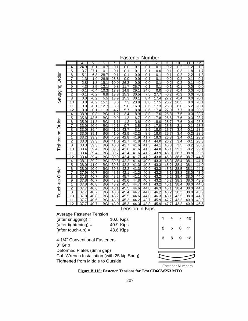
Fastener Number4 5 6 7 8 9 1 2 3 10 11 12
4 24.9 -0.1 -0.7 -0.1 0.0 -0.1 -0.1 0.1 -0.2 -0.2 1.2 1.85 3.7 27.1 -0.1 -0.1 0.1 0.1 0.1 0.0 -0.1 -0.3 1.8 1.76 5.1 6.8 28.7 -0.1 0.1 0.0 0.1 0.1 -0.1 -0.2 2.2 1.37 1.3 1.9 26.9 25.5 0.0 0.0 0.1 0.1 -0.2 -0.2 -0.1 -0.18 2.8 1.8 19.1 10.0 26.3 0.0 0.0 0.1 -0.2 -0.2 -0.1 -0.19 4.3 3.5 13.1 9.8 11.7 25.7 0.1 0.1 -0.1 -0.1 0.0 0.01 -0.1 -0.4 10.3 13.8 14.9 29.1 24.0 0.0 -0.3 -0.4 0.0 -0.12 -0.1 -0.2 6.8 13.8 15.3 30.5 7.5 27.7 -0.2 -0.3 0.0 -0.13 0.0 -0.2 5.5 13.9 15.3 30.1 8.4 17.4 27.2 -0.4 0.0 -0.110 0.0 -0.2 15.1 3.6 7.3 23.8 8.6 17.5 26.7 20.5 0.0 -0.111 0.0 -0.1 12.7 3.9 5.0 16.3 8.6 17.3 26.8 8.0 15.2 -0.112 0.0 -0.1 11.3 4.7 5.7 8.8 8.6 17.4 27.0 7.7 0.0 29.54 38.9 -0.3 BG 1.2 3.4 8.9 8.8 17.6 26.8 7.6 0.3 28.75 35.8 43.5 BG 0.9 1.3 6.7 9.0 17.8 26.6 7.6 0.3 28.76 35.9 41.8 BG 1.1 1.2 3.6 9.0 18.0 25.7 7.6 0.4 28.57 33.0 40.9 BG 42.1 0.7 3.5 8.9 17.9 25.6 3.1 -0.1 28.58 33.0 39.4 BG 41.2 43.7 3.1 8.9 18.0 25.7 3.4 -0.1 28.69 33.0 39.1 BG 41.0 42.9 42.2 8.9 18.0 25.7 3.4 -0.2 28.91 33.2 39.3 BG 40.9 42.8 41.9 41.7 18.3 25.8 3.4 -0.1 28.92 33.3 39.3 BG 41.0 42.7 41.8 41.4 44.0 26.2 3.4 -0.1 28.83 33.3 39.3 BG 40.8 42.7 41.6 41.3 44.1 46.3 3.5 -0.2 28.810 33.4 39.4 BG 39.6 42.6 41.6 41.3 44.0 46.1 39.2 -0.2 29.111 33.4 39.4 BG 39.7 42.4 41.6 41.2 43.9 45.9 38.7 38.8 29.512 33.4 39.4 BG 39.9 42.4 41.7 41.2 43.8 45.8 38.6 38.7 44.64 38.1 39.2 BG 39.8 42.2 41.4 40.9 43.3 45.3 38.4 38.1 44.15 38.0 41.0 BG 39.6 42.2 41.3 40.8 43.3 45.2 38.4 38.1 44.06 38.0 40.9 BG 39.8 42.2 41.3 40.9 43.3 45.3 38.5 38.1 44.17 37.9 40.7 BG 43.5 42.1 41.2 40.8 43.2 45.1 38.3 38.0 43.98 37.8 40.7 BG 43.2 45.7 41.1 40.8 43.2 45.2 38.4 38.0 44.09 37.8 40.7 BG 43.2 45.6 44.8 40.7 43.2 45.2 38.3 38.0 43.91 37.8 40.8 BG 43.2 45.5 44.7 44.1 43.2 45.1 38.4 38.0 44.02 37.7 40.6 BG 43.1 45.5 44.6 44.0 46.3 45.1 38.4 38.0 44.03 37.7 40.7 BG 43.3 45.4 44.7 44.0 46.2 48.2 38.3 38.0 43.910 37.8 40.8 BG 43.2 45.5 44.6 44.0 46.3 48.1 43.5 38.0 44.011 37.7 40.6 BG 43.0 45.3 44.2 43.7 45.9 47.7 43.2 40.9 43.912 37.7 40.7 BG 43.0 45.3 44.3 43.8 45.9 47.7 43.2 40.9 46.6
Tension in KipsAverage Fastener Tension (after snugging) = 10.0 Kips(after tightening) = 40.9 Kips(after touch-up) = 43.6 Kips
4-1/4" Conventional Fasteners3" GripDeformed Plates (6mm gap)Cal. Wrench Installation (with 25 kip Snug)Tightened from Middle to Outside
Fastener Numbers
Snu
ggin
g S
nugg
ing
Ord
erTi
ghte
ning
Ord
erTo
uch-
up O
rder
Figure B.116: Fastener Tensions for Test CD6CW253.MTO
207

05
101520253035404550
4 5 6 7 8 9 1 2 3 10 11 12Fastener Number
Fina
l Ins
talle
d Te
nsio
n (K
ips)
39 Kips
Bad
Gau
ge
Figure B.117: Final Installed Tensions for Test CD6CW253.MTO
0
5
10
15
20
25
30
35
40
4 5 6 7 8 9 1 2 3 10 11 1Installed Fastener Number
Tens
ile L
oad
(Kip
s)
2
Snug
Touch-up
Tight
39 Kip Min.
Figure B.118: Tensile Load History for Fastener #4 - Test CD6CW253.MTO
208

05
101520253035404550
4 5 6 7 8 9 1 2 3 10 11 1Installed Fastener Number
Tens
ile L
oad
(Kip
s)
2
Snug
Tight
Touch-up
39 Kip Min.
Figure B.119: Tensile Load History for Fastener #8 - Test CD6CW253.MTO
05
101520253035404550
4 5 6 7 8 9 1 2 3 10 11 1Installed Fastener Number
Tens
ile L
oad
(Kip
s)
2
Snug
Tight
Touch-up
39 Kip Min.
Figure B.120: Tensile Load History for Fastener #2 - Test CD6CW253.MTO
209

Fastener Number4 5 6 7 8 9 1 2 3 10 11 12
4 22.3 0.0 -0.1 0.0 0.1 0.5 0.0 -0.1 -0.1 1.8 0.7 0.55 5.9 26.6 0.0 0.0 0.1 -0.1 0.0 -0.1 0.0 1.9 1.2 0.66 6.5 5.9 27.4 0.0 0.0 0.0 0.1 -0.1 -0.1 1.8 1.1 0.67 -0.1 3.0 22.8 25.8 0.0 0.0 0.1 0.0 0.0 -0.2 -0.1 -0.38 0.5 3.1 15.5 9.2 25.8 0.0 0.0 -0.1 -0.1 -0.2 0.0 -0.39 1.8 4.9 8.0 8.7 9.4 22.9 0.0 -0.1 -0.1 -0.2 -0.1 -0.31 0.0 0.0 -0.1 9.4 10.7 29.2 21.5 0.0 -0.1 -0.1 -0.1 -0.32 -0.1 0.0 -0.1 10.7 10.2 29.0 2.6 28.1 -0.1 0.4 -0.2 -0.43 -0.1 -0.2 0.0 11.4 10.7 27.4 3.2 9.5 26.3 0.9 -0.1 -0.310 -0.1 0.4 0.1 0.8 3.0 20.8 5.7 11.0 27.3 25.7 -0.1 -0.311 -0.1 0.4 0.2 1.8 1.7 11.6 5.8 10.8 28.0 8.0 22.8 -0.312 -0.1 0.5 0.2 3.7 2.6 2.9 5.7 11.1 28.0 7.8 2.4 27.04 43.0 0.2 0.0 -0.2 -0.1 0.7 0.3 5.8 26.6 6.5 1.8 26.65 31.3 43.3 0.0 -0.2 -0.1 -0.2 1.0 5.2 22.6 6.9 1.4 24.86 31.5 35.3 42.0 0.0 -0.1 -0.1 1.3 6.5 19.6 7.2 1.7 22.87 26.1 33.0 41.4 44.3 -0.1 -0.2 2.0 7.0 19.8 2.0 0.6 22.48 26.5 30.8 39.5 37.9 42.6 -0.2 2.2 7.2 20.1 1.2 0.1 17.79 26.7 30.7 33.3 38.0 38.0 41.1 2.4 7.4 20.8 1.3 0.1 10.71 23.7 31.0 33.5 38.1 37.8 40.7 37.9 4.3 19.3 1.3 0.1 10.72 24.1 31.4 33.7 38.0 37.8 40.4 36.8 43.3 15.0 1.4 0.0 10.73 24.1 31.6 33.8 38.0 37.7 40.4 36.9 41.8 44.6 1.3 0.0 10.910 24.6 31.7 33.9 32.2 33.8 40.0 36.8 41.8 44.3 42.8 -0.3 4.911 24.7 31.7 34.1 33.2 32.4 36.7 36.9 41.8 44.2 39.5 42.5 0.112 24.7 31.7 34.1 33.2 33.2 34.7 36.9 41.8 44.2 39.8 38.3 44.54 42.0 32.5 33.7 32.5 33.2 34.7 36.6 41.7 43.8 39.6 38.2 44.05 41.7 43.2 33.6 32.5 32.9 34.7 36.6 41.7 43.8 39.6 38.1 43.96 41.6 43.0 41.3 32.6 32.9 34.3 36.7 41.8 43.9 39.6 38.1 44.07 41.3 43.0 41.2 42.7 32.8 34.2 36.7 41.8 43.9 39.6 38.2 44.08 41.3 42.9 41.1 42.5 40.7 34.1 36.6 41.7 43.8 39.6 38.1 44.09 41.2 42.8 40.7 42.5 40.5 40.2 36.6 41.8 43.8 39.5 38.2 43.91 41.2 42.7 40.6 42.3 40.5 40.0 37.8 41.8 43.8 39.6 38.1 43.92 41.1 42.7 40.6 42.3 40.4 40.0 37.8 44.1 43.8 39.5 38.1 43.93 41.2 42.7 40.5 42.3 40.4 39.9 37.7 44.1 46.4 39.6 38.1 43.910 41.1 42.6 40.5 42.3 40.3 40.0 37.8 44.1 46.3 42.0 38.1 43.911 41.1 42.7 40.5 42.3 40.3 40.0 37.8 44.1 46.3 42.0 41.0 43.912 41.1 42.7 40.4 42.2 40.3 39.9 37.7 44.0 46.3 41.9 40.9 45.2
Tension in KipsAverage Fastener Tension (after snugging) = 7.6 Kips(after tightening) = 36.4 Kips(after touch-up) = 41.9 Kips
5-1/4" Conventional Fasteners4" GripDeformed Plates (6mm gap)Cal. Wrench Installation (with 25 kip Snug)Tightened from Middle to Outside
Fastener Numbers
Snu
ggin
g S
nugg
ing
Ord
erTi
ghte
ning
Ord
erTo
uch-
up O
rder
Figure B.121: Fastener Tensions for Test CD6CW254.MTO
210

05
101520253035404550
4 5 6 7 8 9 1 2 3 10 11 12Fastener Number
Fina
l Ins
talle
d Te
nsio
n (K
ips)
39 Kips
Figure B.122: Final Installed Tensions for Test
0
510
15
2025
30
3540
45
4 5 6 7 8 9 1 2 3 10 11 1Installed Fastener Number
Tens
ile L
oad
(Kip
s)
2
Snug
Touch-up
Tight
39 Kip Min.
Figure B.123: Tensile Load History for Fastener #4 - Test CD6CW254.MTO
211

212
0
5
10
15
20
25
30
35
40
45
4 5 6 7 8 9 1 2 3 10 11 1Installed Fastener Number
Tens
ile L
oad
(Kip
s)
2
Snug
Tight
Touch-up
39 Kip Min.
Figure B.124: Tensile Load History for Fastener #8 - Test CD6CW254.MTO
0
5
10
15
20
25
30
35
40
45
4 5 6 7 8 9 1 2 3 10 11 1Installed Fastener Number
Tens
ile L
oad
(Kip
s)
2
Snug
Tight
Touch-up
39 Kip Min.
Figure B.125: Tensile Load History for Fastener #2 - Test CD6CW254.MTO

213
APPENDIX C
RESULTS OF CONNECTION TESTS
WITH HUCK C50L FASTENERS

214
INDEX OF FIGURES C-1 Fastener Tensions for Test HD3CS412.MTO .............................................. 215
C-2 Final Installed Tensions for Test HD3CS412.MTO .................................... 216
C-3 Tensile Load History for Fastener # 5 - Test HD3CS412.MTO .................. 216
C-4 Tensile Load History for Fastener # 8 - Test HD3CS412.MTO .................. 217
C-5 Tensile Load History for Fastener # 2 - Test HD3CS412.MTO .................. 217 C-6 Fastener Tensions for Test HD3CS413.MTO .............................................. 218
C-7 Final Installed Tensions for Test HD3CS413.MTO .................................... 219
C-8 Tensile Load History for Fastener # 5 - Test HD3CS413.MTO .................. 219
C-9 Tensile Load History for Fastener # 8 - Test HD3CS413.MTO .................. 220
C-10 Tensile Load History for Fastener # 2 - Test HD3CS413.MTO .................. 220 C-11 Fastener Tensions for Test HD3CS414.MTO .............................................. 221
C-12 Final Installed Tensions for Test HD3CS414.MTO .................................... 222
C-13 Tensile Load History for Fastener # 5 - Test HD3CS414.MTO .................. 222
C-14 Tensile Load History for Fastener # 8 - Test HD3CS414.MTO .................. 223
C-15 Tensile Load History for Fastener # 2 - Test HD3CS414.MTO .................. 223 C-16 Fastener Tensions for Test HD6NS--.MTO ................................................. 224
C-17 Final Installed Tensions for Test HD6NS--.MTO ....................................... 225
C-18 Tensile Load History for Fastener # 5 - Test HD6NS--.MTO ..................... 225
C-19 Tensile Load History for Fastener # 8 - Test HD6NS--.MTO ..................... 226
C-20 Tensile Load History for Fastener # 2 - Test HD6NS--.MTO ..................... 226

Fastener Numbera b c d 5 4 6 7 8 9 1 2 3 10 11 12
a 40.3 0.0 -0.1 0.0 0.0 -0.1 0.3 0.5 -0.1 -0.3 -0.2 -0.2 -0.3 -0.1 -0.1 0.0b 38.7 36.4 0.0 0.2 0.0 0.0 0.4 0.5 0.0 -0.3 -0.1 -0.2 -0.3 -0.2 -0.2 -0.1c 38.2 35.9 47.8 0.2 0.1 0.1 0.4 0.6 0.1 0.0 -0.1 -0.2 -0.3 -0.1 -0.1 0.0
d 38.2 35.6 45.6 48.3 0.0 -0.1 0.2 0.6 -0.1 -0.2 -0.2 -0.3 -0.3 -0.1 -0.2 0.0
5 38.3 34.8 44.9 46.6 40.2 0.0 -0.2 0.6 -0.1 -0.2 -0.1 -0.1 -0.2 0.0 -0.1 0.0a* -0.2 34.8 44.6 46.6 40.2 -0.1 -0.1 0.6 0.0 -0.1 0.0 -0.1 -0.2 -0.1 -0.2 0.04 -0.2 34.9 44.8 46.6 40.0 40.9 0.0 0.8 0.1 -0.1 0.0 -0.1 -0.3 -0.1 -0.2 -0.1b* -0.5 0.1 44.7 46.3 40.2 40.1 0.0 0.8 0.0 -0.2 0.0 -0.2 -0.3 -0.1 -0.2 0.16 -0.3 -0.1 44.7 46.2 39.6 40.1 41.7 0.8 0.0 -0.2 0.0 -0.1 -0.4 -0.1 -0.2 0.0c* -0.3 0.0 -0.4 46.4 39.6 39.8 40.9 0.9 0.0 -0.2 -0.1 -0.2 -0.4 -0.2 -0.3 0.07 -0.2 0.0 -0.4 46.1 39.7 40.0 41.1 40.2 0.1 -0.1 0.0 0.0 -0.2 -0.1 -0.1 0.18 -0.4 0.1 -0.2 46.0 39.7 40.0 41.2 39.3 38.5 0.0 0.0 -0.1 -0.3 -0.1 -0.2 0.0d* -0.1 0.2 -0.2 -0.4 39.5 39.8 40.9 39.2 38.5 -0.2 -0.1 -0.2 -0.3 0.0 -0.1 0.19 -0.2 0.0 -0.4 -0.7 39.4 39.7 40.9 39.0 37.5 39.8 -0.1 -0.2 -0.3 -0.1 -0.2 0.21 -0.2 0.1 -0.3 -0.8 39.4 40.2 40.6 39.0 37.5 39.1 39.8 -0.2 -0.3 0.0 -0.1 0.22 -0.3 0.1 -0.3 -0.7 39.8 40.3 40.6 39.1 37.6 39.2 39.9 40.5 -0.3 0.0 -0.1 0.23 -0.4 0.1 -0.3 -0.6 39.8 40.2 40.9 39.0 37.5 39.0 39.7 40.2 40.9 -0.1 -0.2 0.1
10 -0.3 0.1 -0.3 -0.8 39.7 40.1 40.8 39.0 37.4 39.0 39.6 40.1 40.3 38.2 -0.2 0.111 -0.3 0.0 -0.3 -0.7 39.7 40.2 41.0 39.0 37.8 39.1 39.7 40.2 40.1 38.2 40.7 0.2
12 -0.2 0.0 -0.4 -0.9 39.6 40.1 40.7 38.8 37.6 39.4 39.5 40.0 40.0 37.9 40.7 40.2
Tension in Kips
Average Fastener Tension (after snugging with 4 conventional bolts) = 41.9 Kips(after installation) = 39.5 Kips
28 Grip Huck C50L Fasteners2" GripDeformed Plates (3mm gap)One Pass Intallation Installed from Middle to Outside
Fastener Numbers
Inst
alla
tion
Ord
erS
nug
Figure C.1: Fastener Tensions for Test HD3CS412.MTO
215

0
5
10
15
20
25
30
35
40
45
5 4 6 7 8 9 1 2 3 10 11 12Fastener Number
Fina
l Ins
talle
d Te
nsio
n (K
ips)
39 Kips
Figure C.2: Final Installed Tensions for Test HD3CS412.MTO
0
510
15
2025
30
3540
45
5 4 6 7 8 9 1 2 3 10 11 1Installed Fastener Number
Tens
ile L
oad
(Kip
s)
2
Snug
Tight
Touch-up
39 Kip Min.
Figure C.3: Tensile Load History for Fastener #5 - Test HD3CS412.MTO
216

0
5
10
15
20
25
30
35
40
4 5 6 7 8 9 1 2 3 10 11 1Installed Fastener Number
Tens
ile L
oad
(Kip
s)
2
Snug
Tight
Touch-up
39 Kip Min.
Figure C.4: Tensile Load History for Fastener #8 - Test HD3CS412.MTO
0
5
10
15
20
25
30
35
40
45
4 5 6 7 8 9 1 2 3 10 11 1Installed Fastener Number
Tens
ile L
oad
(Kip
s)
2
Snug
Tight
Touch-up
39 Kip Min.
Figure C.5: Tensile Load History for Fastener #2 - Test HD3CS412.MTO
217
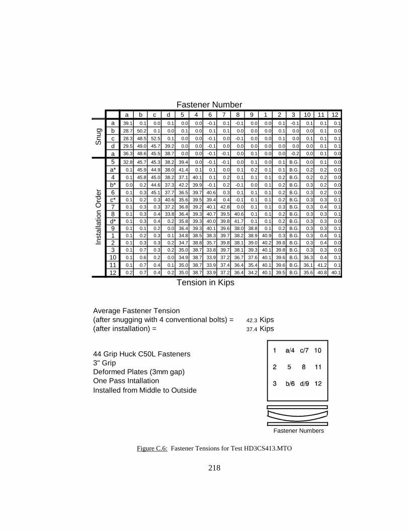
Fastener Number
a b c d 5 4 6 7 8 9 1 2 3 10 11 12a 39.1 0.1 0.0 0.1 0.0 0.0 -0.1 0.1 -0.1 0.0 0.0 0.1 -0.1 0.1 0.1 0.1b 28.7 50.2 0.1 0.0 0.1 0.0 0.1 0.1 0.0 0.0 0.0 0.1 0.0 0.0 0.1 0.0c 28.3 48.5 52.5 0.1 0.0 0.0 -0.1 0.0 -0.1 0.0 0.0 0.1 0.0 0.1 0.1 0.1d 29.5 49.0 45.7 39.2 0.0 0.0 -0.1 0.0 0.0 0.0 0.0 0.0 0.0 0.0 0.1 0.1
a 36.3 48.6 45.5 38.7 0.0 0.0 -0.1 -0.1 0.0 0.1 0.0 0.0 -0.2 0.0 0.1 0.0
5 32.8 45.7 45.3 38.2 39.4 0.0 -0.1 -0.1 0.0 0.1 0.0 0.1 B.G. 0.0 0.1 0.0a* 0.1 45.9 44.9 38.0 41.4 0.1 0.1 0.0 0.1 0.2 0.1 0.1 B.G. 0.2 0.2 0.04 0.1 45.8 45.0 38.2 37.1 40.1 0.1 0.2 0.1 0.1 0.1 0.2 B.G. 0.2 0.2 0.0b* 0.0 0.2 44.6 37.3 42.2 39.9 -0.1 0.2 -0.1 0.0 0.1 0.2 B.G. 0.3 0.2 0.06 0.1 0.3 45.1 37.7 36.5 39.7 40.6 0.3 0.1 0.1 0.1 0.2 B.G. 0.3 0.2 0.0c* 0.1 0.2 0.3 40.6 35.6 39.5 39.4 0.4 -0.1 0.1 0.1 0.2 B.G. 0.3 0.3 0.17 0.1 0.3 0.3 37.2 36.8 39.2 40.1 42.8 0.0 0.1 0.1 0.3 B.G. 0.3 0.4 0.18 0.1 0.3 0.4 33.8 36.4 39.3 40.7 39.5 40.6 0.1 0.1 0.2 B.G. 0.3 0.3 0.1d* 0.1 0.3 0.4 0.2 35.8 39.3 40.0 39.8 41.7 0.1 0.1 0.2 B.G. 0.3 0.3 0.09 0.1 0.1 0.2 0.0 36.4 39.3 40.1 39.6 38.0 38.8 0.1 0.2 B.G. 0.3 0.3 0.11 0.1 0.2 0.3 0.1 34.8 38.5 38.3 39.7 38.2 38.9 40.9 0.3 B.G. 0.3 0.4 0.12 0.1 0.3 0.3 0.2 34.7 38.8 35.7 39.8 38.1 39.0 40.2 39.8 B.G. 0.3 0.4 0.03 0.1 0.7 0.3 0.2 35.0 38.7 33.8 39.7 38.1 39.3 40.1 39.8 B.G. 0.3 0.3 0.0
10 0.1 0.6 0.2 0.0 34.9 38.7 33.9 37.2 36.7 37.6 40.1 39.6 B.G. 36.3 0.4 0.111 0.1 0.7 0.4 0.1 35.0 38.7 33.9 37.4 36.4 35.4 40.1 39.6 B.G. 36.1 41.2 0.1
12 0.2 0.7 0.4 0.2 35.0 38.7 33.9 37.2 36.4 34.2 40.1 39.5 B.G. 35.6 40.8 40.1
Tension in Kips
Average Fastener Tension (after snugging with 4 conventional bolts) = 42.3 Kips(after installation) = 37.4 Kips
44 Grip Huck C50L Fasteners3" GripDeformed Plates (3mm gap)One Pass Intallation Installed from Middle to Outside
Fastener Numbers
Inst
alla
tion
Ord
erS
nug
Figure C.6: Fastener Tensions for Test HD3CS413.MTO
218

0
5
10
15
20
25
30
35
40
45
5 4 6 7 8 9 1 2 3 10 11 12Fastener Number
Fina
l Ins
talle
d Te
nsio
n (K
ips)
39 Kips
Figure C.7: Final Installed Tensions for Test HD3CS413.MTO
05
101520
253035
4045
5 4 6 7 8 9 1 2 3 10 11 12Installed Fastener Number
Tens
ile L
oad
(Kip
s)
Snug
Tight
Touch-up
39 Kip Min.
Figure C.10: Tensile Load History for Fastener #4 - Test HD3CS413.MTO
Bad
Gau
ge
Figure C.8: Tensile Load History for Fastener #5 - Test HD3Cs413.MTO
219

0
5
10
15
20
25
30
35
40
45
4 5 6 7 8 9 1 2 3 10 11 1Installed Fastener Number
Tens
ile L
oad
(Kip
s)
2
Snug
Tight
Touch-up
39 Kip Min.
Figure C.9: Tensile Load History for Fastener #8 - Test HD3CS413.MTO
0
5
10
15
20
25
30
35
40
45
4 5 6 7 8 9 1 2 3 10 11 1Installed Fastener Number
Tens
ile L
oad
(Kip
s)
2
Snug
Tight
Touch-up
39 Kip Min.
Figure C.10: Tensile Load History for Fastener #2 - Test HD3CS413.MTO
220
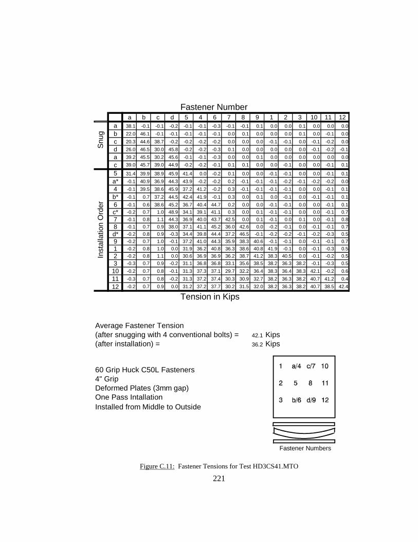
Fastener Number
a b c d 5 4 6 7 8 9 1 2 3 10 11 12a 38.1 -0.1 -0.1 -0.2 -0.1 -0.1 -0.3 -0.1 -0.1 0.1 0.0 0.0 0.1 0.0 0.0 0.0b 22.0 46.1 -0.1 -0.1 -0.1 -0.1 -0.1 0.0 0.1 0.0 0.0 0.0 0.1 0.0 -0.1 0.0c 20.3 44.6 38.7 -0.2 -0.2 -0.2 -0.2 0.0 0.0 0.0 -0.1 -0.1 0.0 -0.1 -0.2 0.0d 26.0 46.5 30.0 45.8 -0.2 -0.2 -0.3 0.1 0.0 0.0 0.0 0.0 0.0 -0.1 -0.2 -0.1a 39.2 45.5 30.2 45.6 -0.1 -0.1 -0.3 0.0 0.0 0.1 0.0 0.0 0.0 0.0 0.0 0.0
c 39.0 45.7 39.0 44.9 -0.2 -0.2 -0.1 0.1 0.1 0.0 0.0 -0.1 0.0 0.0 -0.1 0.1
5 31.4 39.9 38.9 45.9 41.4 0.0 -0.2 0.1 0.0 0.0 -0.1 -0.1 0.0 0.0 -0.1 0.1a* -0.1 40.9 36.9 44.3 43.9 -0.2 -0.2 0.2 -0.1 -0.1 -0.1 -0.2 -0.1 -0.2 -0.2 0.04 -0.1 39.5 38.6 45.9 37.2 41.2 -0.2 0.3 -0.1 -0.1 -0.1 -0.1 0.0 0.0 -0.1 0.1b* -0.1 0.7 37.2 44.5 42.4 41.9 -0.1 0.3 0.0 0.1 0.0 -0.1 0.0 -0.1 -0.1 0.16 -0.1 0.6 38.6 45.2 36.7 40.4 44.7 0.2 0.0 0.0 -0.1 -0.1 0.0 0.0 -0.1 0.1c* -0.2 0.7 1.0 48.9 34.1 39.1 41.1 0.3 0.0 0.1 -0.1 -0.1 0.0 0.0 -0.1 0.77 -0.1 0.8 1.1 44.3 36.9 40.0 43.7 42.5 0.0 0.1 -0.1 0.0 0.1 0.0 -0.1 0.88 -0.1 0.7 0.9 38.0 37.1 41.1 45.2 36.0 42.6 0.0 -0.2 -0.1 0.0 -0.1 -0.1 0.7d* -0.2 0.8 0.9 -0.3 34.4 39.8 44.4 37.2 46.5 -0.1 -0.2 -0.2 -0.1 -0.2 -0.3 0.59 -0.2 0.7 1.0 -0.1 37.2 41.0 44.3 35.9 38.3 40.6 -0.1 -0.1 0.0 -0.1 -0.1 0.71 -0.2 0.8 1.0 0.0 31.9 36.2 40.8 36.3 38.6 40.8 41.9 -0.1 0.0 -0.1 -0.3 0.52 -0.2 0.8 1.1 0.0 30.6 36.9 36.9 36.2 38.7 41.2 38.3 40.5 0.0 -0.1 -0.2 0.53 -0.3 0.7 0.9 -0.2 31.1 36.8 36.8 33.1 35.6 38.5 38.2 36.3 38.2 -0.1 -0.3 0.5
10 -0.2 0.7 0.8 -0.1 31.3 37.3 37.1 29.7 32.2 36.4 38.3 36.4 38.3 42.1 -0.2 0.611 -0.3 0.7 0.8 -0.2 31.3 37.2 37.4 30.3 30.9 32.7 38.2 36.3 38.2 40.7 41.2 0.4
12 -0.2 0.7 0.9 0.0 31.2 37.2 37.7 30.2 31.5 32.0 38.2 36.3 38.2 40.7 38.5 42.4
Tension in Kips
Average Fastener Tension (after snugging with 4 conventional bolts) = 42.1 Kips(after installation) = 36.2 Kips
60 Grip Huck C50L Fasteners4" GripDeformed Plates (3mm gap)One Pass Intallation Installed from Middle to Outside
Fastener Numbers
Inst
alla
tion
Ord
erSn
ug
Figure C.11: Fastener Tensions for Test HD3CS41.MTO
221

0
5
10
15
20
25
30
35
40
45
5 4 6 7 8 9 1 2 3 10 11 12Fastener Number
Fina
l Ins
talle
d Te
nsio
n (K
ips)
39 Kips
Figure C.12: Final Installed Tensions for Test HD3CS414.MTO
0
510
15
2025
30
3540
45
5 4 6 7 8 9 1 2 3 10 11 1Installed Fastener Number
Tens
ile L
oad
(Kip
s)
2
Snug
Tight
Touch-up
39 Kip Min.
Figure C.13: Tensile Load History for Fastener #5 - Test HD3CS414.MTO
222

0
5
10
15
20
25
30
35
40
45
4 5 6 7 8 9 1 2 3 10 11 1Installed Fastener Number
Tens
ile L
oad
(Kip
s)
2
Snug
Tight
Touch-up
39 Kip Min.
Figure C.14: Tensile Load History for Fastener #8 - Test HD3CS414.MTO
0
5
10
15
20
25
30
35
40
45
4 5 6 7 8 9 1 2 3 10 11 1Installed Fastener Number
Tens
ile L
oad
(Kip
s)
2
Snug
Tight
Touch-up
39 Kip Min.
Figure C.15: Tensile Load History for Fastener #2 - Test HD3CS414.MTO
223

Fastener Number4 5 6 7 8 9 1 2 3 10 11 12
4 42.1 0.2 0.1 0.0 -0.1 0.0 0.1 0.2 0.2 0.1 0.4 0.15 36.3 39.6 0.1 0.0 0.0 0.0 0.3 0.1 0.1 0.0 0.9 0.06 36.4 36.9 44.8 0.0 0.2 0.0 0.2 0.0 0.1 0.0 0.6 0.27 35.4 35.0 43.2 36.4 0.0 0.0 0.3 0.1 0.1 0.1 0.3 0.28 33.6 34.5 42.9 26.0 42.0 0.0 0.5 0.1 0.1 0.1 0.6 0.29 33.7 34.5 42.1 25.2 36.0 39.4 0.2 0.0 0.0 0.0 0.7 0.21 33.6 33.9 41.3 25.3 36.0 38.6 40.0 0.1 0.1 0.0 0.6 0.32 34.0 34.1 39.9 25.2 36.1 38.6 39.7 38.9 0.2 0.1 0.7 0.33 34.5 34.2 39.7 25.2 36.1 38.5 39.4 38.7 40.7 0.1 0.9 0.410 34.4 34.1 39.7 22.5 34.8 38.0 39.4 38.6 40.0 38.3 0.8 0.411 34.8 34.0 39.5 22.4 34.4 36.9 39.2 38.6 40.0 38.8 38.0 0.312 34.7 34.0 39.5 22.4 34.5 36.4 39.2 38.5 39.8 38.5 38.1 43.6
Tension in Kips
Average Fastener Tension (after Installation) = 36.6 Kips
28 Grip Huck Fasteners2" GripDeformed Plates (6mm gap)One Pass InstallationTightened from Middle to Outside
Fastener Numbers
Inst
alla
tion
Figure C.16: Fastener Tensions for Test HD6NS--2.MTO
224

0
5
10
15
20
25
30
35
40
45
4 5 6 7 8 9 1 2 3 10 11 12Fastener Number
Fina
l Ins
talle
d Te
nsio
n (K
ips)
39 Kips
Figure C.17: Final Installed Tensions for Test HD6NS--2.MTO
0
510
15
2025
30
3540
45
4 5 6 7 8 9 1 2 3 10 11 1Installed Fastener Number
Tens
ile L
oad
(Kip
s)
2
Snug
Tight
Touch-up
39 Kip Min.
Figure C.18: Tensile Load History for Fastener #4 - Test HD6NS--2.MTO
225

0
5
10
15
20
25
30
35
40
45
4 5 6 7 8 9 1 2 3 10 11 1Installed Fastener Number
Tens
ile L
oad
(Kip
s)
2
Snug
Tight
Touch-up
39 Kip Min.
Figure C.19: Tensile Load History for Fastener #8 - Test HD6NS--2.MTO
0
5
10
15
20
25
30
35
40
4 5 6 7 8 9 1 2 3 10 11 1Installed Fastener Number
Tens
ile L
oad
(Kip
s)
2
Snug
Tight
Touch-up
39 Kip Min.
Figure C.20: Tensile Load History for Fastener #2 - Test HD6NS--2.MTO
226

227
BIBLIOGRAPHY 1. “Load and Resistance Factor Design Specification for Structural Joints Using ASTM
A325 or A490 Bolts”, Research Council on Structural Connections of the Engineering
Foundation, June 1988.
2. Kulak, G.L., Fisher, J.W., and Struik, J.A., Guide to Design Criteria for Bolted and
Riveted Joints, Second Edition, John Wiley and Sons, New York, 1987.
3. Kulak, G.L., and Obaia, K.H., “A Field Study of Fastener Tension in High-Strength
Bolts”, Structural Engineering Report No. 177, Department of Civil Engineering,
University of Toronto, April 1992.
4. Notch, J.S., “A Field Problem with Preload of Large A490 Bolts”, The Structural
Engineer, Volume 64A, No. 4, April 1986.
5. Foreman, R.T., and Rumpf, J.L., “Static Tension Tests of Compact Bolted
Joints”,Transactions of the American Society of Civil Engineers, Volume 126-Part 2, 1961,
pp. 228-254.
6. Birkemoe, Peter C., “Installation Tension of High-Strength Bolts in Connections with
Out-of-Flat Plates”, IABSE International Colloquium, Bolted and Special Structural Joints,
USSR, Moscow, May 1989.

BIBLIOGRAPHY 1. “Load and Resistance Factor Design Specification for Structural Joints Using ASTM A325 or
A490 Bolts”, Research Council on Structural Connections of the Engineering Foundation,
June 1988.
2. Kulak, G.L., Fisher, J.W., and Struik, J.A., Guide to Design Criteria for Bolted and Riveted
Joints, Second Edition, John Wiley and Sons, New York, 1987.
3. Kulak, G.L., and Obaia, K.H., “A Field Study of Fastener Tension in High-Strength Bolts”,
Structural Engineering Report No. 177, Department of Civil Engineering, University of
Toronto, April 1992.
4. Notch, J.S., “A Field Problem with Preload of Large A490 Bolts”, The Structural Engineer,
Volume 64A, No. 4, April 1986.
5. Foreman, R.T., and Rumpf, J.L., “Static Tension Tests of Compact Bolted Joints”,
Transactions of the American Society of Civil Engineers, Volume 126-Part 2, 1961,
pp. 228-254.
6. Birkemoe, Peter C., “Installation Tension of High-Strength Bolts in Connections with
Out-of-Flat Plates”, IABSE International Colloquium, Bolted and Special Structural Joints,
USSR, Moscow, May 1989.