Embed Size (px)
Citation preview

This document is downloaded from DR‑NTU (https://dr.ntu.edu.sg)Nanyang Technological University, Singapore.
Coordination control of hybrid AC/DC buildingmicrogrid
Zhu, Dexuan
2017
Zhu, D. (2017). Coordination control of hybrid AC/DC building microgrid. Doctoral thesis,Nanyang Technological University, Singapore.
http://hdl.handle.net/10356/71914
https://doi.org/10.32657/10356/71914
Downloaded on 29 Nov 2021 03:14:39 SGT

COORDINATION CONTROL OF HYBRID AC/DC BUILDING
MICROGRID
ZHU DEXUAN
INTERDISCIPLINARY GRADUATE SCHOOL
ENERGY RESEARCH INSTITUTE @ NTU (ERI@N)
2016

COORDINATION CONTROL OF HYBRID AC/DC BUILDING
MICROGRID
ZHU DEXUAN
Interdisciplinary Graduate School
Energy Research Institute @ NTU (ERI@N)
A thesis submitted to the Nanyang Technological University in partial
fulfilment of the requirement for the degree of
Doctor of Philosophy
2016


Statement of Originality
I hereby certify that the work embodied in this thesis is the result of original research and has not
been submitted for a higher degree to any other University or Institution.
. . . . . 8/AUG/2016 . . . . . . . . . . . . . . . . . . . . . . . . . . . . . . . . .
Date ZHU DEXUAN


Abstract
i
Abstract
Advantages such as environmental friendliness and flexibility have made microgrid
an attractive option for in modern power systems. Microgrid is a localized grouping
of distributed generators, storages and loads. Microgrid integrates with sustainable
energy sources could reduce carbon emission. A microgrid can serve specific
purposes, such as to enhance reliability, diversification of energy sources, and cost
reduction. Therefore, microgrid has been introduced into building distributed
networks as it makes both power generation and consumption more efficient. In
order to obtain better power conversion and utilization efficiency, the configuration,
control strategy, and energy management of building microgrid need to be further
studied. This thesis introduces the overall configuration of building microgrid and
the specific subsystem controllers in a building microgrid.
Microgrid configuration, operation and control have been investigated for many
years. Various microgrid configurations for building distributed networks have
been proposed with each claiming some aspects of improvements. To achieve better
energy efficiency, a novel hybrid building microgrid is introduced in this thesis. A
building photovoltaic system (BPVS), a building motor drive system (BMDS) and
a hybrid building energy storage system (HBES) are introduced respectively based
on the common features among PV systems, motor driving circuits and various
energy storages. The objective of the building hybrid microgrid (BHMG) is to
improve building’s energy efficiency through reducing multiple reverse conversion
loss in conventional building distributed networks (CBDN), to achieve more
efficient connection of subsystems, and to reduce building energy consumption and
peak power demand through power generation from BPVS and power regeneration
in BMDS.
In building microgrid, motor drives are essential devices and widely used in lifts,
air-conditioning and water pumping systems. In a high rise commercial building,
lift motors not only consume energy but also regenerate energy. A building’s lift

Abstract
ii
system is proposed to classify and integrate all lifts together to improve the
efficiency in the building’s energy utilization. A novel distributed lift control
approach based on fuzzy logic and DTC is proposed in this chapter to integrate lift
operating system optimization and motor control. The objective of the novel control
system is to choose the lift which makes the waiting & riding time shorter and
consumes less power, and it can even regenerate power and channel back into
energy storage. The motor controller with self-tuning has a smaller ripple and
shorter response and recovery time. By using this controller, the power efficiency
in high rise multi story building can be improved.
Another essential component in building microgrid is energy storage. Different
types of energy storages with high power density and high energy density have to
operate under different modes like voltage regulation and power exchange. An
adaptive area droop control approach has been proposed to demonstrate an
autonomous mode change and a stable operating performance for energy storage
converters. The coordination control is introduced to reduce the battery
charging/discharging times of miner cycle and discharge depth.
Plug-in hybrid electric vehicle (PHEV) is gaining popularity in today's automotive
market and more charge stations for PHEV are installed in commercial buildings.
The conventional charge circuit can only produce an output DC voltage that is
higher than the peak AC input voltage. An efficient single-phase PFC converter that
features sinusoidal input current, three-level output characteristic and flexible
output DC voltage is introduced to cater for variable voltage levels of the battery
pack (50V-600V). The charging efficiency is improved since it is partially
contributed by the reduced switching voltage in the PFC stage, and also partially
by the reduced power conversion in the DC/DC buck stage.
All design configurations and control algorithms have been thoroughly verified in
MATLAB/Simulink and PLECS. Suitable experimental prototypes have been built
in the laboratory for validating the practicalities of all theoretical findings.

Acknowledgements
iii
Acknowledgements
The author would like to extend his gratitude to those who have encouraged and
helped the author in his research life and making this report as a success. Without
their guidance and knowledge, this thesis would not have been successfully
completed.
First and foremost, the author is especially grateful to his supervisor, Associate
Professor Wang Peng, for the guidance and help during the research period. He has
always been concerned about what the students have learnt and what problems they
have encountered.
In particular, the author would like to express his sincerest gratitude to Assistant
Professor Tang Yi and Professor Chan Siew Haw, they taught the author to do the
hardware implement and helped him in finishing the experiment.
The appreciation is also extended to Dr Jin Chi and Dr Xiao Jianfang, who
introduced the hybrid AC/DC microgrid and basic control idea to the author and
also encouraged him to finish this report.
The author is also grateful to all the technicians in Water Energy Research
Laboratory. They have assisted and guided him on the methods of how to use the
best equipment.
At last, the author would like to thanks Mrs. Shi Guang. She helps the author to
improve the writing and review the typo & grammar mistakes.

Acknowledgements
iv

Table of Contents
v
Table of Contents
Abstract……………………………………………………………………………………i
Acknowledgements……………………………………………………………………...iii
Table of Contents………………………………………………………………………...v
Table Captions…………………………………………………..……………………….ix
Figure Captions ............................................................................................................ xi
Abbreviations ............................................................................................................ xvii
Chapter 1 Introduction ................................................................................................. 1
1.1 Background .......................................................................................................... 2
1.2 Objectives ............................................................................................................ 4
1.2.1 Decrease multiple reverse conversion loss to improve system efficiency .............. 4
1.2.2 Decrease maximum load demand ......................................................................... 4
1.2.3 Optimize the lift operation ................................................................................... 5
1.2.4 Simplify the hybrid energy storage controller ....................................................... 5
1.2.5 Extend the DC output voltage range ..................................................................... 5
1.3 Thesis Overview ................................................................................................... 6
1.4 Originality ............................................................................................................ 8
Chapter 2 Existing Topology and Control Techniques for Building Microgrid ......... 9
2.1 Introduction ........................................................................................................ 10
2.2 Basic Conception of Building Distributed Network ............................................. 10
2.2.1 Conventional Building Distributed Network Configuration ................................. 11
2.2.2 Smart Building Definition and Building Attributes Classification ........................ 15
2.3 Control Strategy of Building Distributed Network .............................................. 16
2.3.1 Control Strategy of Hybrid Microgrid ................................................................. 16
2.3.2 Control Strategy of Motor Drive ......................................................................... 18
2.3.3 Control Strategy of Energy Storage ..................................................................... 22
2.3.4 Control Strategy of Power Factor Correction ...................................................... 23

Table of Contents
vi
2.4 Summary ............................................................................................................ 26
Chapter 3 A Smart Building Hybrid Microgrid for Energy Efficiency
Improvement ............................................................................................ ……………27
3.1 Introduction ........................................................................................................ 27
3.2 Smart Building Hybrid Microgrid Architecture ................................................... 29
3.3 Operation and Control of each subsystem in BHMG ........................................... 32
3.3.1 Operation and Control of Building Motor Drive System (BMDS) ....................... 32
3.3.2 Operation and Control of HBES………………………………………………....33
3.3.3 Operation and Control of Building Photovoltaic System (BPVS) ........................ 34
3.4 Coordination Control of BHMG ......................................................................... 34
3.4.1 Mode 0 ............................................................................................................... 36
3.4.2 Mode 1 ............................................................................................................... 38
3.4.3 Mode 2 ............................................................................................................... 40
3.5 Transit Analysis during Different Operation Modes ............................................ 40
3.5.1 Mode 0 ............................................................................................................... 40
3.5.2 Mode 1 ............................................................................................................... 42
3.5.3 Mode 2 ............................................................................................................... 43
3.6 System Studies Results ....................................................................................... 45
3.7 Summary ............................................................................................................ 51
Chapter 4 Distributed Lift Operating Control in Smart Building Hybrid
Microgrid ................................................................................................. ……………53
4.1 Introduction ........................................................................................................ 54
4.2 Lift Control System ............................................................................................ 54
4.3 Description of Operating Operation Controller.................................................... 55
4.3.1 Layer I ............................................................................................................... 56
4.3.2 Layer II .............................................................................................................. 57
4.3.3 Layer III ............................................................................................................. 58
4.3.4 Layer IV ............................................................................................................. 60
4.3.5 Layer V .............................................................................................................. 60
4.4 Description of Motor Controller ......................................................................... 60
4.5 System Studies Results ....................................................................................... 62
4.6 Summary ............................................................................................................ 66

Table of Contents
vii
Chapter 5 Adaptive Area Droop Control for Hybrid Energy Storage System in
Building Hybrid Microgrid ........................................................................................ 67
5.1 Introduction ........................................................................................................ 68
5.2 Building System Configuration ........................................................................... 68
5.2.1 System Configuration ......................................................................................... 68
5.2.2 Hybrid Energy Storage System Operating Modes ............................................... 69
5.3 Description of Adaptive Area Droop Control ...................................................... 70
5.3.1 Definition of droop characteristic ........................................................................ 70
5.3.2 Voltage regulation ............................................................................................... 72
5.3.3 Power exchange ................................................................................................. 73
5.3.4 Adaptive droop area control ................................................................................ 75
5.3.5 Steady-State and Dynamic Analysis of the Proposed Controller .......................... 81
5.4 Coordination Control of Hybrid Energy Storage System in BHMG ..................... 82
5.5 System Studies Results ....................................................................................... 84
5.6 Summary ............................................................................................................ 87
Chapter 6 A PFC Converter with Flexible Output Voltage and Improved Efficiency
in Building Hybrid Microgrid .................................................................................... 89
6.1 Introduction ........................................................................................................ 90
6.2 Converter Description and the Operation Principle ............................................. 91
6.3 Converter Controller Design ............................................................................... 96
6.3.1 PFC Converter Control ....................................................................................... 96
6.3.2 Buck Converter Control ...................................................................................... 99
6.3.3 Discussion on Alternative Control Strategies ...................................................... 101
6.4 System Studies Results ..................................................................................... 102
6.5 Summary .......................................................................................................... 110
Chapter 7 Conclusion and Future Work .................................................................. 111
7.1 Conclusion ....................................................................................................... 112
7.2 Future Work ..................................................................................................... 114
Publications ............................................................................................................... 119
References ................................................................................................................. 121

Table of Contents
viii

Table Captions
ix
Table Captions
Table 2.1 Building attributes classification…………………………………15
Table 3.1 The parameters of the compact system…………………………...42
Table 3.2 The details of BHMG operation………………………….……….46
Table 3.3 The details of CBDN operation…………………………………...46
Table 5.1 The parameters of the simulation implementation………………..82
Table 6.1 Circuit parameters used for simulation and experiment………….100
Table 6.2 Key component used for experiment prototype…………….…….103

Table Captions
x

Figure Captions
xi
Figure Captions
Figure 2.1 AC microgrid configuration. …………………………….……….. 11
Figure 2.2 Conventional building distributed network…………………….….12
Figure 2.3 DC microgrid configuration……………………………………….13
Figure 2.4 Hybrid microgrid configuration…………………………………...14
Figure 2.5 Control block diagram of DTC……………………………………….19
Figure 3.1 Smart building hybrid microgrid architecture……………………...29
Figure 3.2 Building motor drive system operating modes…………………….32
Figure 3.3 Control block diagram of the HBES……………………………….33
Figure 3.4 The schematic diagram of the compact BHMG……………………35
Figure 3.5 DC side droop characteristic: (a) Common DC bus droop
characteristic; (b) Low voltage DC bus droop characteristic; (c) Nominal droop
characteristic………………………………………………………………….….36
Figure 3.6 Control block diagram of bidirectional DC/DC converter for mode
0……………………………………………………………………………….….37
Figure 3.7 DC side droop characteristic when there is power transfer between
AC and DC sides…………………………………………………………………38

Figure Captions
xii
Figure 3.8 Control block diagram of bidirectional DC/DC converter for mode 1
& 2…………………………………………………………………………….….39
Figure 3.9 Time average model of the converters for the idle mode………….40
Figure 3.10 Control block diagram of the converter and BDCC in the idle
mode……………………………………………………………………………...40
Figure 3.11 Time average model of the converters for the mode 1…………….42
Figure 3.12 Control block diagram of the converter and BDCC in mode 1……42
Figure 3.13 Time average model of the converters for the mode 2…………….43
Figure 3.14 Control block diagram of the converter and BDCC in mode 2……44
Figure 3.15 Operating performance of BHMG…………………………………47
Figure 3.16 Operating performance of CBDN…………………………………49
Figure 4.1 Overall block diagram of lift control system………………………55
Figure 4.2 Lift motor operating optimization controller………………………55
Figure 4.3 Detailed description of fuzzy logic layers………………………….56
Figure 4.4 Control block diagram of motor controller………………………...61
Figure 4.5 Speed loop Fuzzy-PID controller………………………………….62
Figure 4.6 Compact Model of Passenger Lift System…………………………63

Figure Captions
xiii
Figure 4.7 Optimal scheduling results of building lift system…………………63
Figure 4.8 Operating performance of two motors………………………….….64
Figure 4.9 Motor 1 voltage and current……………………………………….64
Figure 4.10 The results from the conventional DTC and the self-tuning DTC….65
Figure 5.1 Building system configuration…………………………………….69
Figure 5.2 Droop characteristic definition…………………………………….71
Figure 5.3 Voltage regulation droop control……………………………….….73
Figure 5.4 Power exchange droop control…………………………………….74
Figure 5.5 Definition of adaptive area………………………………………...76
Figure 5.6 Battery converter operating point changing in the adaptive area (Idc
decrease condition)……………………………………………………………….78
Figure 5.7 Battery converter operating point changing in the adaptive area (Idc
increase condition)……………………………………………………………….79
Figure 5.8 Operating point out of the adaptive area (O.P place on ev edge)…..80
Figure 5.9 Operating point out of the adaptive area (O.P place on Ps edge)…..81
Figure 5.10 Control mode diagram of energy storage converters………………83
Figure 5.11 Control mode diagram of energy storage converters………………84

Figure Captions
xiv
Figure 5.12 Simulation results of the operating point still in the adaptive area after
a sudden change……………………………………………………………….….86
Figure 5.13 Simulation results of the operating point out of the adaptive area after
a sudden change and placed on voltage error edge………………………………87
Figure 5.14 Simulation results of the operating point out of the adaptive area after
a sudden change and placed on power exchange edge……………………….….87
Figure 6.1 Circuit diagram of proposed three-level PFC converter for single-
phase PHEV chargers……………………………………………………………91
Figure 6.2 Idealized operating waveforms for proposed three-level PFC
converter…………………………………………………………………………93
Figure 6.3 Instantaneous power distribution in PFC converter and buck
converter, given fixed gird voltage, output voltage, and dc-link voltage…….….94
Figure 6.4 3D plot of equ. (6.7)……………………………………………………..96
Figure 6.5 Overall control block diagram for the proposed three-level PFC
converter…………………………………………………………………………98
Figure 6.6 Bode diagrams of original system (dotted line), type III compensator
(dashed line), and compensated system (solid line)…………………………….100
Figure 6.7 Simulated steady-state waveforms under 230-V/2-kW
operation…………………………………………………………………….….103
Figure 6.8 Experimental steady-state waveforms under 230-V/2-kW
operation…………………………………………………………………….….104

Figure Captions
xv
Figure 6.9 Experimental load step-down waveforms………………………105
Figure 6.10 Experimental load step-up waveforms………………………….106
Figure 6.11 Harmonic contents of the output voltage and high dc bus voltage
under 230-V/2-kW operation………………………………………………….107
Figure 6.12 Experimental steady-state waveforms under 120-V/1-kW
operation………………………………………………………………………107
Figure 6.13 Grid current spectrum at 230-V/2-kW operation and 120-V/1-kW
operation, shown in comparison with the IEC 61000-3-2 Class A harmonic current
limits……………………………………………………………………….….108
Figure 6.14 Efficiency curves of the proposed PFC converter under universal
input voltages, shown in comparison with the conventional two-stage
solution...............................................................................................................109
Figure 6.15 Efficiency curve of the proposed PFC converter under different
output voltages, shown in comparison with the conventional two-stage
solution…………………………………………………………………...……109
Figure 7.1 Motor MPC operating process……………………………….....116
Figure 7.2 Control block diagram for motor – energy storage system……..117

Figure Captions
xvi
Abbreviations
xvii
Abbreviations
CBDN Conventional Building Distributed Network
BHMG Building Hybrid Microgrid
CDCB Common DC Bus
LDCB Low Voltage DC Bus
BDAC Bi-directional DC/AC Converter
BPVS Building Photovoltaic System
HESS Hybrid Energy Storage System
HBES Hybrid Building Energy Storage System
BMDS Building Motor Drive System
DTC Direct Torque Control
PFC Power Factor Correction
V2G Vehicle to Grid
MPC Model Predictive Control

Abbreviations
xviii

Introduction Chapter 1
1
Chapter 1
Introduction
Buildings are considered to be among the largest energy consumption
unites in modern cities. With the increase of building energy
consumption, the drawbacks of conventional building power
distributed network topology arise progressively. The theme of this
thesis is to design a novel building hybrid microgrid and its
coordination control. Each subsystem in this novel building hybrid
microgrid is designed to improve the whole system efficiency and meet
specific requirements. The objectives and structure of this thesis are
introduced in this chapter.

Introduction Chapter 1
2
1.1 Background
For over hundreds of years, power grid has been expanded into today’s giant
network which can cover an entire country as big as China or Canada with several
hundreds of large conventional fossil generators. In such large scaled power grid,
buildings are always considered as large energy consumption units. Based on the
building energy data book from U.S Departure of Energy [1], transportation,
industrial plants and buildings are three large energy consuming sectors. 41% of
primary energy is consumed by the buildings sector, compared to 30% by the
industrial sector and 29% by the transportation sector. Twenty quads of delivered
energy, which does not include energy loss during production and transmission, is
consumed in a year. With the growth in population, households and commercial
floor space, the energy consumption in the building sector keeps growing.
With the building energy consumption growth, the drawbacks of conventional
topology of building power distributed network in large scale power grids arise
progressively. Conventional energy depletion in buildings and the associated
environmental problems are becoming public concerns. Based on the statistics from
The Energy Information Administration (EIA), 75% of the energy sources used by
the building sector come from fossil fuels, 16% from nuclear generation and 9%
from renewables. The other downside is that, long distance transmission and large
network not only cause instability and security problems of grid operation but also
could not meet the diverse requirements of power supply.
To overcome those energy shortcomings and meet specific requirements, the
concept of microgrid was proposed and introduced into building power networks.
Microgrid is the localized grouping of distributed generators, storages and loads.
Building distributed networks were used to be established as microgrid with
conventional power generation. Accompanying the penetration of renewable
energy sources, microgrids with integrated sustainable energy sources have been
developed into the worldwide. It could meet localized requirements and make both
Introduction Chapter 1
3
power generation and consumption more efficient. Conventional building
distributed network is AC microgrid integrated with renewable energy sources such
as PV or fuel cell. In order to obtain better power conversion and utilization
efficiency, building distributed network needs to be further studied in the areas of
configuration, control strategy, and energy management.
In building energy consumption, the top four end usages are space heating, space
cooling, water heating and lighting, which account for 68% of total energy
consumption in the building. The new issue about how to reduce the peak load
demand arises. A promising method is to use regenerative energy from motor drives
since it is widely used in space temperature control and lift system. The controller
for motor drive has to be improved to meet requirements such as to generate (or
regenerate) more energy, to maintain constant speed and achieve faster response.
Energy storage is recognized as the key to improving the reliability and dynamic
stability of building distributed networks due to the penetration of large amount of
intermittent and stochastic power [2]. For large stationary energy storages in the
power grid, the advantages include peak power shaving, load levelling and standby
reserves [3]. In building distributed networks, the energy storage has capacity and
sizing limitations. At the same time, energy storage has to meet the high frequency
power exchange requirement by the motor drive operation system. The question
about which kind of energy storage and proper controller is truly more stable is
therefore left unanswered.
With these challenges to explore and the growing importance of building
distributed networks, the theme of this thesis is firmly set on the design of building
hybrid microgrid configuration and its coordination control. For further study, each
subsystem in building distributed networks has to be designed to improve efficiency.
Issues such as lift operation optimization, power transfer loss reduction, converter
controller simplification and feedback variables self-tuning are promptly discussed.
The relevant topics are now elaborated as follows.

Introduction Chapter 1
4
1.2 Objectives
A number of objectives, which are supposed to be achieved throughout the course
of this research, are explained as follows:
1.2.1 Building system energy efficiency improvement
A novel smart building hybrid microgrid (BHMG) is proposed to improve buildings’
energy efficiency through reducing multiple reverse conversion loss in
conventional building distributed networks (CBDN), to achieve highly efficient
connection of subsystems. Multi-level voltage DC bus is proposed in the BHMG
for easier and more efficient integration of various DC links which exist in the
motor driving circuits, energy storages, loads and PV systems of the CBDN. A
common DC bus (CDCB) and a low voltage DC bus (LDCB) are introduced to
reduce energy loss from multiple reverse conversions such as DC/AC/DC and
AC/DC/AC in CBDN, also to realize direct power exchange between generation
(or regeneration) and consumption, as well as to eliminate some parts of redundant
hardware such as rectifier in many loads.
1.2.2 Maximum building load demand reduction
In conventional building distributed networks, motor drives are considered as large
energy consumers. The regenerative energy is wasted as heat generated by resist
friction and or dumped back into the utility grid. In BHMG, the regenerative power
from motor drives is reused or restored back in the energy storage. Among the
motor drives, the regenerative energy can be used for powering the other motors
even loads. The maximum load demand is reduced by designing the motor
controller which is to maximize the regenerative power during regenerative braking
and to share the power between different operating mode motors.
Introduction Chapter 1
5
1.2.3 Optimal lift operation
For further improvement, a novel distributed lift control approach based on fuzzy
logic and DTC is proposed to integrate lift operating optimization and motor control.
Lift operating optimization method is based on the fuzzy logic. The inputs of the
fuzzy logic-based optimization are real time call level, original level and destination
level, which are the 3 key areas of a real-life lifts operation system. The motor
controller is designed based on the DTC. A fuzzy self-tuning method is introduced
in motor controller. The proportional and integral gains in controller can be self-
tuning according to the lift operation. The novel approach is set for each motor in
a building’s lift system. By using this method, the lift operation is optimized and
the peak power demand can be reduced.
1.2.4 Simplify the hybrid energy storage controller
Based on the building microgrid configuration, hybrid building energy storage
system (HBES) has different operating modes. Energy storage converters are able
to work in either voltage regulation mode or power exchange mode. The proposed
adaptive area droop control is introduced to HBES which could automatically alter
the energy storage operating mode by changing the droop coefficient. The energy
storage converter does not need multiple controllers to achieve different objectives.
This also means that the energy storage converter is simplified.
1.2.5 Extend the DC output voltage range
A highly efficient single-phase PFC converter features sinusoidal input current,
three-level output characteristic and flexible output DC voltage. Its attractiveness
is that the embedded bidirectional DC/DC buck converter only needs to process
partial input power rather than full scale of input power, and therefore energy
conversion efficiency can be largely improved compared with the conventional two
stage solution. Also, the PFC stage exhibits three-levels of output voltage, and the
Introduction Chapter 1
6
dV/dt across the switches are reduced, so as the switching losses. An added
advantage of this converter is that, the fluctuating 100Hz or 120Hz harmonic power
in the single-phase system can be almost diverted into the DC link capacitor through
proper control design, and the terminal voltage and/or the charging current of
battery pack will be fairly constant, which may extend its working lifetime.
1.3 Thesis Overview
This thesis addresses eight chapters organized as follow:
Chapter 1 provides the rationale for the research and outlines the goals and scope
as well as summarizes all original contributions documented in the thesis.
Chapter 2 reviews the literature concerning conventional building distributed
networks and its control strategy. It discusses the essential relationships among the
various types of microgrid and their control strategy. The relative devices controller
such as motor controller and energy storage controller are reviewed as well. Recent
related developments are also discussed with their benefits and limitations
identified. The knowledge gained helps in the understanding of new control
schemes and generalized design procedures proposed from chapter 3 onwards.
Chapter 3 introduces the concept of smart building hybrid microgrid and its
coordination control. The novel configuration is proposed for improving the
building energy efficiency and reducing the building energy consumption and
maximum load requirement. In the building hybrid microgrid, a building
photovoltaic system (BPVS), a building motor drive system (BMDS) and a hybrid
building energy storage system (HBES) are introduced respectively. The following
chapters will discuss the improvement on them.
Chapter 4 elaborates on the improvement on building motor drive system (BMDS),
especially the lifts in building microgrid. The distributed lift operation control is

Introduction Chapter 1
7
proposed in this chapter. The novel controller integrates optimized operation
controller and motor DTC controller with self-tuning PID. The fuzzy logic is
introduced into the lift control system to optimize operation and self – tuning in
motor DTC control. The presented controller is compared with existing alternatives
to clearly identify their steady – state and dynamic performance.
Chapter 5 elaborates on the improvement of hybrid energy storage system. An
adaptive area droop controller is designed to switch HBES from voltage regulation
mode to power control mode automatically by changing the droop coefficient. The
mathematical analysis is presented in this chapter to verify the validation.
Chapter 6 presents a high efficiency single-phase PFC converter that features
sinusoidal input current, three-level output characteristic and flexible output DC
voltage. Its attractiveness is that the embedded bidirectional DC/DC buck converter
only needs to process partial input power rather than full scale of input power, and
therefore its conversion efficiency can be much improved compared with the
conventional two stage solution. Also, the PFC stage exhibits three-level output
voltage, and the dV/dt across the switches are reduced, so as the switching losses.
An added benefit of this converter is that, the fluctuating 100Hz or 120Hz harmonic
power in the single-phase system can be diverted into the dc-link capacitor through
proper control design, and the terminal voltage and/or the charging current of
battery pack will be fairly constant, which may expand its working lifetime. Its
operation principle and control strategies are discussed in detail in this paper, and
both simulations and experimental results are provided for validation.
Chapter 7 concludes the research findings presented in this thesis and suggests
some prospective research topics for future investigation.

Introduction Chapter 1
8
1.4 Originality
This research led to several novel outcomes by:
1. Design of a novel smart building hybrid microgrid configuration and its
coordination control
2. Design of a novel lift distributed control which correlates lift optimize
operation and motor DTC control. By using the novel controller, the
response time is reduced and makes a better performance
3. Improve an adaptive droop area control for hybrid energy storage system
which can automatically change the operation modes by tuning the droop
coefficient
4. Design of a PFC converter with flexible output voltage to improve the energy
efficiency which is used as EV charger
5. Improve a motor controller with MPC which is able to achieve multiple
objectives

Existing Techniques Chapter 2
9
Chapter 2
Existing Topology and Control Techniques for Building
Microgrids
In this chapter, some fundamental studies which include building
distributed network configuration, attributes classification and their
controllers are reviewed. Conventional building distributed network is
based on AC microgrid, which is introduced in this chapter. The
essential components such as motor drives and energy storages are
necessary to achieve the smart building requirement. DTC and fuzzy
logic controller are introduced into motor drive control. The hybrid
energy storage system is the promising method to improve the efficiency.
The details are introduced in the following sections.
Existing Techniques Chapter 2
10
2.1 Introduction
With the rapid growth of population, the cities become more crowded. To achieve
more efficient land usage, more high-rise and multi-story buildings appear in mega
cities. According to the recent data and forecasts from U.S. Department of Energy
(DOE), buildings, especially commercial buildings, are the largest energy
consuming units in the modern world [4]. A promising way to control this
continuously rising global energy consumption is to improve building energy
utilization efficiency. To realize this, building distributed network (CBDN) has to
meet the requirements which are explicitly described in following certain
commanded references. Designing a proper building distributed network
configuration and controller for each subsystem in CBDN configuration is therefore
crucial and has in fact been a relevant topic for many microgrid applications.
Various microgrid configurations for building distributed networks have been
proposed with each claiming some aspects of improvement. This chapter briefly
reviews fundamental microgrid concepts and introduces the basic coordination
control that is popular and relevant to the research contributions of this thesis. There
are many power devices in the microgrid such as PV panels, motor drives and
different types of energy storages. For each device controller, many references have
proposed some improving techniques. Materials presented in the following sections
in this chapter are therefore not exhaustive, but would definitely help with
understanding of concepts proposed in the subsequent chapters.
2.2 Building Distributed Network
In this chapter, some basic concepts about smart building and microgrid are
introduced before reviewing the existing control schemes for building distributed
network. Understanding of these basic concepts helps greatly with control design
targeted in building microgrid.

Existing Techniques Chapter 2
11
2.2.1 Conventional Building Distributed Network Configuration
In early times, buildings are considered as large loads which are connected to the
utility grid. Accompanying the penetration of renewable energy sources, many
renewable energy sources are connected into the building power system. The
building distributed network becomes a microgrid which is a cluster of loads and
micro sources operating as a single controllable system that provides both power and heat
to its local area. The first generation building distributed network is based on the
main AC bus which is connected to the utility grid. Hence, the first generation
conventional building distributed network is an AC microgrid [5]. Fig. 2.1 shows
the basic configuration of AC microgrid.
Figure 2.1 AC microgrid configuration.
Under AC topology, DC inherent renewable energy sources such as PV conversion
systems are integrated to conventional AC systems through DC/DC/AC inverters.
Moreover, continuously increasing DC loads requires AC/DC rectifiers for
connection to AC grids. AC microgrids can control the active power through the
demand reactive power, as well as supply the reliable power when the system is
disconnected from the utility grid if utility grid faults occur [6] [7] [8] [9] [10] [11].

Existing Techniques Chapter 2
12
CBDN as shown in Fig. 2.2 is designed for easy connection of loads on AC sides.
However, AC/DC rectifiers are required in CBDN for fundamental loads on DC
sides. Motor-driving loads such as air conditioning and lift systems are connected
to CBDN through AC/DC/AC converters. There are many hidden DC links as
shown in Fig. 2.2. Among all loads, building’s lift and air conditioning systems are
critical and special loads because of their contribution to building’s maximum
power demand and energy consumption [12]. In CBDN, motors in lifts and some
of air conditioning systems are connected to AC bus in parallel through AC/DC/AC
converters and operate separately as shown in Fig. 2.2.
Figure 2.2 Conventional building distributed network.
With the development of renewable energy sources and electric vehicles (EVs) in
recent years, building distribution network has become more complicated. In
CBDN, power from rooftop PV systems is dumped to grid through DC/AC grid-
tied inverters. Therefore, the same power from PV can only be used to supply local
DC loads through another AC/DC converter. Battery energy storages are inherent
DC loads. An AC/DC rectifier is required for EV connection to CBDN. In order to
reduce the effect of intermittence and uncertainty of renewable power sources,
energy storage systems are connected to CBDN through Bi-directional DC/AC
Converters (BDAC).
Obviously, there are inherent multiple DC/AC and AC/DC reverse conversions in

Existing Techniques Chapter 2
13
CBDN, which result in additional power loss and cost from unnecessary converters.
The recessive individual DC links in various converters make system control more
complex. Many AC/DC converters and AC/DC inverters in CBDN can be
eliminated. Therefore, a smart building microgrid is proposed in next section to
reduce multiple reversion conversion, simplify network configuration and improve
energy utilization efficiency.
Conversions between DC and AC devices in AC microgrid reduce system
efficiency based on the nonlinear stability analysis in [13] [14]. DC microgrids are
becoming more popular due to their higher efficiency and easier to be controlled
than AC microgrids [15] [16]. DC microgrids predominately generate, distribute
and use electrical energy in native DC form at low voltage. Moreover, DC
microgrids are able to be connected to and operate in conjunction with AC power
grids to form smart grids [17]. Based on this, DC microgrid is introduced into
building distributed network. The DC microgrid configuration is represented in Fig.
2.3.
Figure 2.3 DC microgrid configuration.
Many research studied DC microgrid. In [18], a detailed description and analysis
for a DC microgrid by using small signal model is introduced. However, multiple
Existing Techniques Chapter 2
14
reverse conversions for AC loads and sources still exist in DC microgrids. Two-DC
bus topology was proposed for high efficient V2G applications [19]. In recent years,
many rooftop PV systems have been installed in buildings around the world to
harness energy. Different topologies of rooftop PV inverters are investigated in [20].
Power imbalanced operation is a common problem for CBDN. A detailed
description about a comprehensive voltage imbalance sensitivity analysis and
stochastic evaluation has been presented [21].
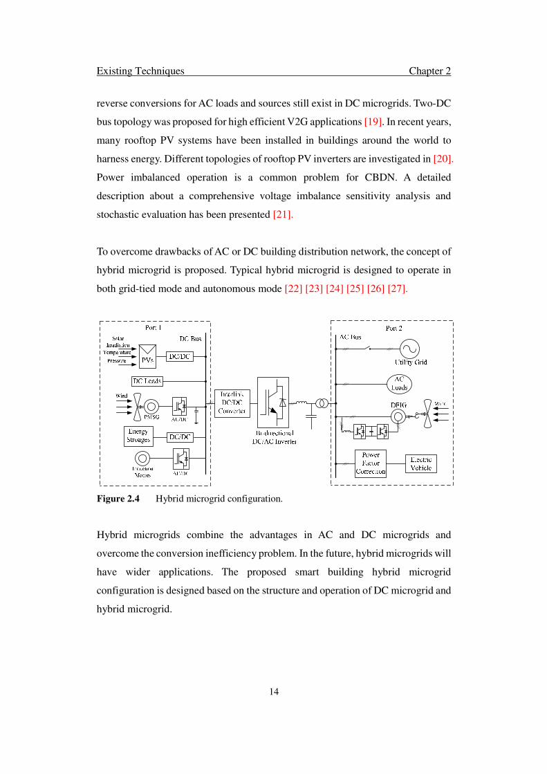
To overcome drawbacks of AC or DC building distribution network, the concept of
hybrid microgrid is proposed. Typical hybrid microgrid is designed to operate in
both grid-tied mode and autonomous mode [22] [23] [24] [25] [26] [27].
Figure 2.4 Hybrid microgrid configuration.
Hybrid microgrids combine the advantages in AC and DC microgrids and
overcome the conversion inefficiency problem. In the future, hybrid microgrids will
have wider applications. The proposed smart building hybrid microgrid
configuration is designed based on the structure and operation of DC microgrid and
hybrid microgrid.

Existing Techniques Chapter 2
15
2.2.2 Smart Building Definition and Building Attributes Classification
Smart building is a newly proposed concept. Building owners, designers,
contractors and facility managers are all trying to build or renovate buildings
identified as “smart” buildings. In general, smart buildings are innovative, with
advanced technology and materials, contributing to reduced energy usage and the
sustainability of the building, and providing more efficient and effective operation
[28].
Although buildings are too complex and the features of a smart building are
numerous, some attributes have to be considered in the building distributed network
configuration to serve its purpose. In this thesis, various types of electrical devices
are considered as the attributes in smart building. Table 2.1 shows the building
attributes classification [29].
Table 2.1 Building attributes classification
Attributes Description
Communication/Data Infrastructure Plug Load
Network and Security Fundamental Load
Digital Lighting Control System Fundamental Load
Plumbing and Water Motor Load
Access Control System (ACS) Plug Load
Video Surveillance System Fundamental Load
Fire Alarm Fundamental Load
Audio/Visual Plug Load
Metering Plug Load
Occupant Satisfaction Plug Load
Integrated Building Management System Fundamental Load
Lifts Motor Load
Air-Conditions Motor Load

Existing Techniques Chapter 2
16
Building loads consist of three parts. One is the fundamental load such as lighting
system or water pump, which consumes energy all the time during a day. The
fundamental loads make building operate properly. Another one is the plug load,
which is the electricity used for electrical appliances. This kind of loads satisfy the
building’s occupants everyday needs. Plug loads make up 20 - 30% of energy loads
in commercial buildings [30]. The last one is the motor-driving loads. Motor drives
are widely used in lifts, air-conditions and water pumps. In conventional building
distributed network, motor drives are considered as large energy consumption units
since the regenerated power from motors is usually burned by a resistance or sent
back to the grid in CBDN. In the proposed smart building configuration which is
introduced in the next chapter, the motor drive is considered as a partial-consuming
load because of the re-usage or restoring of regenerative power.
2.3 Control Strategy of Building Distributed Network
Many techniques about microgrid and its components controller have been studied.
The following sections concentrate on the basic and related control strategies of the
same topic.
2.3.1 Control Strategy of Hybrid Microgrid
Microgrid controls require to integrate different technologies and control strategies
of power electronics, telecommunications, distributed generators and distributed
storages system together [31]. Many publications have discussed the control
strategy in microgrids in both grid-tied mode and isolated mode.
In [32], a decentralized parallel inverter control is proposed for microgrid operation.
The droop control is introduced into generators. The frequency is set by output
active power. The magnitude of voltage is set by the reactive power. Therefore,
distribution system is able to operate without PLLs. Moreover, load active and
reactive powers can be shared according to the converter ratings. However, this

Existing Techniques Chapter 2
17
paper just assumes the distributed loads are dominantly inductive. The harmonic
current of nonlinear load sharing strategy is discussed in [33]. Decentralized
parallel inverter control is focus on the grid-tied mode.
In [34], the hierarchical control is proposed for microgrids, and can operate in both
grid-tied mode and isolated mode. The hierarchical control consists of three levels.
The primary control deals with the inner control of the DG units by adding virtual
inertias and controlling their output impedances. This level is implemented by
sensing the local variable. The control objectives are to share the total load,
guarantee stability on DC or AC subgrid and actively damp oscillations between
the output filters. The secondary control is conceived to restore the frequency and
amplitude deviations produced by the virtual inertias and output virtual impedances.
They are different measures and correspond with each other by the
telecommunication in the whole grid. The tertiary control regulates the power flows
between the grid and the microgrid at the point of common coupling (PCC). This
level does the power balance in the whole grid and transfers the power
automatically based on the load condition. Much research has been done focusing
on the specific elements in microgrid, which is in the first and second level as
described above. However, the coordination control of the whole grid is less
complete in previous research. The coordination control of microgrids stabilizes the
PCC voltages, determines the direction of power flow and manages the whole grid
energy [35] [36] [37] [38] [39] [40].
Moreover, the solutions for energy efficiency improvement in hybrid microgrid are
proposed in recent publications. In [41], a hierarchical power scheduling approach
to manage the system power, which consists of user utility, transmission cost, grid
load variance and to minimize the power generation and transmission cost. In [42],
a load shifting demand side management technique is investigated to shift building
loads in response to time of day tariff which is in turn, able to reduce peak energy
in the existing distribution system. However, these existing publications do not
consider the realistic device efforts like regenerative energy from motor drives in
Existing Techniques Chapter 2
18
building microgrid.
2.3.2 Control Strategy of Motor Drive
The motor control method is relatively mature. There are many types of motors
used in building distributed networks. Most common type is induction motor.
Reference [43] investigates motor with energy storage topology. The motor
controller is designed based on the dual-loop control. Reference [44] investigates
the field oriented control (FOC) and direct torque control (DTC) methods in detail.
Comparing with the FOC control strategy, DTC has some advantages such as no
current control loop, no need for coordinate transformation. These features make
the controller respond fast. Since a lift moves up and down frequently, fast response
is a basic requirement. The DTC method was implemented in [45]. Since the lift
operating mode changes frequently, the proportional and integral gains of the
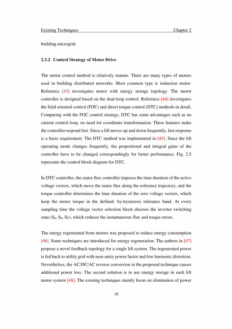
controller have to be changed correspondingly for better performance. Fig. 2.5
represents the control block diagram for DTC.
In DTC controller, the stator flux controller imposes the time duration of the active
voltage vectors, which move the stator flux along the reference trajectory, and the
torque controller determines the time duration of the zero voltage vectors, which
keep the motor torque in the defined- by-hysteresis tolerance band. At every
sampling time the voltage vector selection block chooses the inverter switching
state (Sa, Sb, Sc), which reduces the instantaneous flux and torque errors.
The energy regenerated from motors was proposed to reduce energy consumption
[46]. Some techniques are introduced for energy regeneration. The authors in [47]
propose a novel feedback topology for a single lift system. The regenerated power
is fed back to utility grid with near-unity power factor and low harmonic distortion.
Nevertheless, the AC/DC/AC reverse conversion in the proposed technique causes
additional power loss. The second solution is to use energy storage in each lift
motor system [48]. The existing techniques mainly focus on elimination of power

Existing Techniques Chapter 2
19
peak and sizing of super capacitors to compensate rated power for a single lift [49].
However, when lift motors are operating in different modes, the direct power
exchange among the two or more lifts are not considered. Different motor operation
modes affect the building distributed network operation.
abc/αβ
ia ib ic
SVPWM
Sa* Sb
* Sc*
d/dt
θr
PI
ωr
Induction
Motor
Motor Converter
+- ωr*
Clark Transform
Rs Rs
iαs iβs Vαs Vβs
+
+
-
-
∫ ∫ψαs
ψβs
X
X
Te*
+ -3P/2
+ - Te
PI
∫+
ωsl+* ωs
*
Clark Transform
Voltage Calculation
+
+
-
-
Vαs Vβs* *
Flux & Torque
Estimation
ψs*
VDC
Figure 2.5 Control block diagram of DTC.
In the regenerative braking control strategy, the most important variable is braking
torque. [50] proposed an optimal torque determination. A mathematical model of
rotor is represented as:
�� = ���� + �� (2.1)

Existing Techniques Chapter 2
20
In which �� is torque; � is inertia of rotor; is damping coefficient; �� is rotor
angular speed. �� is determined by the motor operation condition. �� is positive for
motor acceleration. �� is negative because of power regeneration.
Since the iron loss is too small, the induction motor interior power loss is the sum
of rotor and stator copper loss. The interior power loss is described as:
�� = ����� ��� + ��������� + ��� �������� (2.2)
where � and �� represent the stator and rotor resistance respectively; �� is the
mutual inductance; �� is rotor inductance; �� is rotor flux; � is pole number. From
the control strategy described in chapter 5.2, �� is constant by the control. Hence, �� is a function with one variable ��.
The output power of induction motor as generator is represented as:
�!" = −���� (2.3)
The regeneration power is derived as:
��$�% = �!" − �� (2.4)
The ��$�% is derived as:
��$�% = − ��������� + ��� &�'�������� − (1 + ��������� + ��� �*�����+ ���� �� − (1 + ��������� + ��� *�����+ ��� − ����� ��� (2.5)
Assuming that the motor operates on the generator condition in the time
interval ,-. -/0, the integrated regeneration work in the time interval is derived
from ��$�% as:
1��$�% = 2 ��$�% 3-"4"5 (2.6)
If 1��$�% has extremum value, it means that regeneration power is at appropriate
point. Since 1��$�% depends on �� and ��� , the behaviour of �� is derived by using

Existing Techniques Chapter 2
21
calculus of variations. The optimal torque can be obtained from the behaviour of ��
and ��. Equation of ��$�% is differentiated partially with respect to �� and ��� , the
equations change to follow equations:
6 78��9�:7'�� = −2 ��������� + ��� &�'�������� − (1 + ��������� + ��� �*�����+ ���78��9�:7'� = − (1 + ��������� + ��� �*�����+ �� − 2 (1 + ��������� + ��� *�����+ ��� (2.7)
The Euler’s equation:
<<" �78��9�:7'�� � = 78��9�:7'� (2.8)
The complete form of equation is:
− ��������� + ��� &������ ��= + (1 + ��������� + ��� *�����+ �� = 0 (2.9)
If 1��$�% has extremum value, �� is represented as:
�� = ?@A� B−C *&� � + �������������D����� � -E + F@A� BC*&� � + �������������D����� � -E (2.10)
The optimal torque �� is derived from ��.
�� = B−�C *&� � + �������������D����� � + E ?@A� B−C *&� � + �������������D����� � -E + B�C *&� � + �������������D����� � + E F@A� BC*&� � + �������������D����� � -E (2.11)
where ? and F are coefficients from following equations.
GHIHJ�. = ?@A� B−C *&� � + �������������D����� � -.E + F@A� BC *&� � + �������������D����� � -.E
�/ = ?@A� B−C *&� � + �������������D����� � -/E + F@A� BC *&� � + �������������D����� � -/E (2.12)
where �. is rotor speed at -.; �/ is rotor speed at -/; ,-. -/0 is time interval when
the motor is working on the generator mode.

Existing Techniques Chapter 2
22
From the above analysis, the optimal torque �� or optimal rotor speed �� for the
regeneration is obtained from �., �/, -. and -/. The optimal torque is used in the
lift motor controller.
Fuzzy controller is used to optimize lift operation and improve the lift motor
performance. Fuzzy logic is an approach of computation based on ‘degrees of truth’
rather than the usual ‘true or false’ (1 or 0) Boolean logic on which the modern
computer is based. The fuzzy logic is based on the implementation of human
understanding and human thinking in control algorithms, which is able to improve
the response speed even if the system is complex. In recent publications, fuzzy
controller is introduced into optimal operation of lift system. A general method for
minimizing passenger waiting time within a reasonable limit has been proposed
[51]. The fuzzy logic algorithm has been implemented in the optimization. A fuzzy
BP neutral network for multiple elevator operation is introduced to further improve
the performance of lift system [52]. However, the input data such as the average
waiting time, power consumption, and floor traffic, etc. are not online data which
cannot be sensed and used directly. The lift operating optimization is usually
controlled by a central controller.
2.3.3 Control Strategy of Energy Storage
Hybrid energy storage system is constituted of super capacitors and batteries as the
core and the auxiliary storage system respectively since supercapacitors are of high
power density, with long servicing life and small size, light weight energy storage
units [53] [54] [55].
The existing studies about hybrid energy storages mainly focus on the specific use
and its controller. Hybrid energy system is widely used in Wind-PV system. Study
[56] gives detailed description of controller which can avoid the possibility of
overcharging and discharging of battery. The current control is used for
supercapacitor in this energy storage system. However, the controller in this

Existing Techniques Chapter 2
23
publication has not done the power sharing between the energy storages. Study [57]
introduces an adaptive droop control which has a fast transient response for close-
loop system and ensures the optimal operation of voltage source inverter. The other
application of a hybrid energy storage system for grid connected and standalone
wind energy application is given in [58] and [59].
These literatures particularly focus on the performance of the hybrid energy storage
system rather than considering the system level investigations. Moreover, the
application of hybrid energy storage system in building microgrid has received little
research attention. The other aspect which attracts researchers is how to prolong the
battery life in hybrid energy storage system. The common method is to sort out high
and low frequency variations and reduce the battery operating time. Authors in [60]
explained the method which could sort out the high and low frequency variations.
The common method is to use wavelet analyses. However, a central controller is
requested for frequency separation. Another method mentioned in [61] is using high
and low pass filter to do the net power decomposition. This method could separate
frequencies in distributed controller, but cannot enhance the damping of microgrids
nor guarantee the stable operation. In this paper, coordination control of hybrid
energy storage system is proposed to determine an activate sequence of battery and
supercapacitor based on the system variations and it is able to prolong the battery
life as well.
2.3.4 Control Strategy of Power Factor Correction
AC/DC converter is one of the most common power conversion systems and can
be found in many industrial as well as residential applications, for example, variable
speed drive, electric vehicle chargers, and power supplies for consumer electronics.
In order to meet the ever more stringent grid codes like the IEC61000-3-2 harmonic
limits, high-power factor and sinusoidal current regulation are required for
basically all such applications as long as their power ratings exceed 75 W [62].
Existing Techniques Chapter 2
24
Presently, single-phase power factor correction (PFC) converter is a very popular
solution to ensure the compliance of such regulations because of its simplicity, cost
effectiveness, and good current shaping capability. However, most of the existing
single-phase PFC converters are of boost type and can only provide an output
voltage that is higher than the peak voltage of the ac input [63] [64] [65] [66] [67].
Wide range of output voltage is indeed desired in some applications like plug-in
hybrid electric vehicle (PHEV) charging systems where the terminal voltage of
battery packs may vary between 100 V and 600 V [68], depending on their
configuration and state-of-charge. In this case, a second stage DC/DC buck
converter has to be implemented to further step down the PFC output voltage,
which undoubtedly decreases the overall system efficiency.
In order to provide flexible DC output voltages, PFC converters with buck–boost
capabilities have been studied in past literatures and they are usually based on buck-
boost, fly back, Cuk, and single-ended primary inductance converter (SEPIC)
topologies, and can be derived in both non-isolated and isolated versions [69] [70]
[71] [72] [73]. A common problem for these topologies is that there is no direct
energy transfer path during power conversion and all input power must be
processed by active switches and stored by intermediate passive components (either
inductors or capacitors) before being supplied to the end loads [74].
This indicates that the components will be working under increased voltage/current
stresses, which may consequently lead to decreased power density and conversion
efficiency. In order to improve the performance of Cuk and SEPIC-based PFC
topologies, their bridgeless variants have recently been proposed in [75] [76] [77]
[78] with most of them being operated in discontinuous conduction mode (DCM).
In this case, the PFC converter can be constructed with less semiconductor switches
and the on-state conduction losses can be reduced. The switching losses are reduced
as well due to their DCM operation. However, the main power switches in these
bridgeless topologies are still under high-voltage stress and the DCM operation also

Existing Techniques Chapter 2
25
implies that they are only suitable for relatively low-power applications because of
the high peak current in the boost inductor.
In view of this, AC/DC converters with direct buck capability are highly desirable
in high-power PHEV battery charger applications and a buck-type PFC topology,
named as Swiss Rectifier which has already been proposed in [79] and [80] for
three phase AC/DC systems. For single-phase AC/DC rectifiers, a lot of researches
have been recently carried out to study the performance and operation of a buck-
topology-based PFC converter [81] [82] [83] [84] [85] [86], which can produce a
lower output DC voltage and meanwhile maintain high efficiency under universal
line voltage. The bridgeless derivative of the buck PFC was also proposed in [87]
to further improve its conversion efficiency.
Unfortunately, such buck PFC converters may be inherently subject to a so-called
“dead angle” limitation when the input voltage is lower than the output voltage.
The AC side input current cannot be regulated to be purely sinusoidal and unity
power factor is not achievable. An improved buck PFC converter with high-power
factor is proposed in [88], where an auxiliary switch and two diodes are added in
the circuit to provide current regulation during the “dead angle” period. Although
the power factor can be improved, the input current waveform is still not sinusoidal
and therefore, they may only be suited for low-power applications (less than 1 kW),
such as laptop adapter and TV sets power supplies. Another buck PFC converter
with power decoupling capability has recently been proposed in [89], and it features
high-quality input current as well as ripple free output voltage.
However, the limitation of this topology is that, its output voltage must be lower
than half of the peak AC input voltage, and this may largely constrain the output
voltage range during low-line operation. Some integrated bidirectional AC/DC and
DC/DC converter topologies were proposed in [90], [91], which combines all
necessary operation modes that are required for the power converter of PHEVs,
namely plug-in charging from power grid, vehicle-to-grid discharge, pumping

Existing Techniques Chapter 2
26
power to drive electric motor, and regenerative braking. Despite its powerful
functionalities, these converters involve a number of semiconductor devices, and
therefore, it may not be an efficiency optimized and cost-effective solution.
2.4 Summary
This chapter reviews some of the existing building distributed networks and their
controller. Conventional building distributed network is based on AC microgrid.
Environmental incentives, local customer demand and economic are changing the
system of electricity generation and transmission from the AC power grids to
microgrids. Buildings have to meet the smart building requirements. Although
buildings are too complex and the features of a smart building are too numerous,
some attributes have to be considered in the building distributed network
configuration to achieve these objectives. The essential components in smart
building such as motor drives and energy storages and their controller are reviewed
as well. DTC and fuzzy logic controller are introduced into motor drive controller.
Hybrid energy storage is the promising method to increase the efficiency. To a great
extent, a smart building hybrid microgrid configuration and its coordination control
is investigated in chapter 3 based on the fundamental studies review in this chapter.

Smart Building Hybrid Microgrid Chapter 3
27
Chapter 3
A Smart Building Hybrid Microgrid for Energy Efficiency
Improvement
A novel building AC/DC hybrid microgrid (BHMG) is proposed in this
chapter. A building photovoltaic system (BPVS), a building motor drive
system (BMDS) and a hybrid building energy storage system (HBES)
are introduced respectively based on the common features of PV
systems, motor driving circuits and various energy storages. The
objective of the BHMG is to improve building energy efficiency through
reducing multiple reverse conversion loss in conventional building
distributed networks (CBDN), to achieve efficient connection of
subsystems, and to reduce building energy consumption and peak
power demand through power generation from BPVS and power
regeneration in BMDS. A common DC bus (CDCB) and a low voltage
DC bus (LDCB) are proposed to reduce inefficiency from multiple
reverse conversions and to realize direct power exchange between
power regeneration and consumption in CBDN. A HBES, which adopts
the advantages of different energy storages, is proposed to mitigate
system operating problems. Smart distributed control is implemented
for coordinating the operation of BMDS, BPVS and HBES. The
proposed BHMG structure is verified through simulations.
*This section published substantially as D. Zhu and P. Wang, “A Smart Building Hybrid Microgrid
for Energy Efficiency Improvement”. IEEE Transactions on Smart Grid, under review.
Smart Building Hybrid Microgrid Chapter 3
28
3.1 Introduction
According to the recent data and forecasts from U.S. Department of Energy (DOE),
buildings, especially commercial buildings, are the largest energy consuming units
in the modern world. A promising way to control continuously rising global energy
consumption is to increase building energy utilization efficiency. Microgrid is an
appropriate infrastructure for improving building energy efficiency [92]. The
common features of loads and distributed generations in CBDN have been
investigated in chapter 2. The obvious disadvantages of the conventional building
power grid are large maximum load demand and high multiple reverse conversion
loss.
In this chapter, the improved building hybrid microgrid configuration and its
distributed control are introduced. The contribution of the current study contains
two aspects. A novel hybrid AC/DC building microgrid (BHMG) configuration is
proposed for improving the building energy efficiency and reducing the building
energy consumption and maximum load demand. The BHMG is a three-bus three-
subsystem configuration which integrates a building photovoltaic system (BPVS),
a hybrid building energy storage system (HBES) and a building motor drive system
(BMDS) together. A common DC bus (CDCB) and a low voltage DC bus (LDCB)
are proposed to reduce efficiency loss from multiple reverse conversions such as
DC/AC/DC and AC/DC/AC in CBDN, to realize direct power exchange between
generation (or regeneration) and consumption, and to eliminate parts of hardware
such as rectifier in many loads. The voltage of CDCB is a good indication of system
power balance between AC and DC subgrids. High and Low frequency components
are used for trigging the operation of supercapacitor and battery. The HBES is
proposed to eliminate the disadvantages of different energy storages to mitigate
different system problems. The other aspect is the smart distributed control for the
BHMG. Smart distributed control is implemented for coordination control to
maintain the reliable and stable operation of BHMG under variable sources and
loads conditions.

Smart Building Hybrid Microgrid Chapter 3
29
3.2 Smart Building Hybrid Microgrid Architecture
The proposed smart building hybrid microgrid architecture is shown in Fig. 3. 1.
Figure 3.1 Smart building hybrid microgrid architecture.
A two-level DC network is proposed for easy and efficient integration of various
DC links which exist in the motor driving circuits, energy storages, loads and PV
systems of the CBDN. CDCB is proposed for the connection of all motors through
DC/AC converters, which eliminates the AC/DC rectifiers of motor driving circuits
in CBDN. Energy storage systems can also be connected to the CDCB through
DC/DC converters to replace the more complicated AC/DC/DC converters in
CBDN. The voltage level for the CDCB is selected based on the voltage of the
hidden DC links in lift and air conditioning systems. In a CBDN, PV systems and
DC energy storages and electric vehicles are connected to AC network through
various DC/AC inverters. In such connection, PV panels or battery cells are
connected in series or through DC/DC booster in order to achieve the required
minimum DC voltage for efficient connection to AC network. LDCB is proposed
for BPVS and low voltage DC loads, which can further reduce multiple DC/DC/DC
conversion due to direct power exchange between PV systems and DC loads. The
voltage level for the LDCB is selected based on easy connection of DC loads and
Smart Building Hybrid Microgrid Chapter 3
30
PV systems. A common BDAC is proposed for power exchange between DC and
AC bus to eliminate AC/DC rectifiers for individual loads in CBDN. A common
bidirectional DC/DC converter (BDCC) is proposed between CDCB and LDCB to
reduce the boost ratio of individual DC/DC converters. Three sub-systems are
proposed for the high efficient connection of motors, energy storages and PV panels.
In CBDN, each motor is controlled individually no matter it is in motor driving
mode (MDM) or regenerative braking mode (RBM). The regenerated power is
usually burned by a resistance or sent back to the grid in CBDN. In BHMG, the
BMDS connected CDCB is proposed in this chapter. The CDCB integrates all the
DC links in the BMDS for direct power exchange among motors operating in
different modes. Hence, the energy consumption of the BMDS and maximum
demand are reduced.
BPVS is connected to LDCB to directly supply some of DC loads to further reduce
DC/DC conversions. To avoid the complexity of power management and enforce
coincident control strategy to distributed storages, the HBES connected to the
CDCB is proposed to operate as a common energy buffer. The HBES with different
power and energy density can be controlled coordinately to compensate low and
high frequency voltage variations. Supercapacitors are used to provide high power
density to reduce the short time maximum demand when motors in BMDS change
the operation mode. Supercapacitor capacity is determined by motor drive system
and derived byregen regernW P=∑ , where motor regenerative power is derived as
2 22 2
2 2 2 2 2 2
22 2
2 2 2 2
2( ) [1 ( ) ]
[1 ( ) ]
s r s rrregen r r r r
m r m r
s r sr r r
m r m
R L R LJ DP R R J
L p L p
R L RDR D
L p L
ω ω ωϕ ϕ
ω ϕϕ
= − + − + +
− + + −
&&
(3.1)
Rs and Rr represents the stator and rotor resistance respectively; Lm is the mutual
inductance; Lr is rotor inductance; φr is rotor flux; p is pole number; J is inertia of
rotor; D is damping coefficient; ωr is rotor angular speed.

Smart Building Hybrid Microgrid Chapter 3
31
Batteries are used to store regenerative energy from BMDS and energy surplus
from BPVS during peak solar duration and low load demand. The HBES direct
connection to the CDCB makes it easy for power exchange among BPVS, BMDS
and HBES. The total hybrid energy storage system size is determined according to
the value for 5 days of autonomy days building energy consumption data. The total
capacity of HBES is bounded by
5
0day
HBES
b
EE
DOD η∗
≤ ≤∗
(3.2)
where HBESE is capacity of HBES, dayE is maximum energy consumption of single
day, bη is the conversion efficiency and we assume the efficiency is 95% [93].
There are four advantages from this new configuration. First, instantaneous power
generated from lifts and air condition motors in RBM can be instantly observed by
other motors operating in MDM. Therefore, the size of energy storage rating is
reduced. The second advantage is that CDCB eliminates AC/DC conversion stage
for all motor-driven converters. Only DC/AC converters are required for the motors
in lifts and air conditioners. The size of the equipment will be reduced. The control
and operation of motors becomes easy. The third advantage is that two-level DC
network is more efficient because of the boost ratio of DC/DC converter is reduced
for PV connections and low voltage DC loads can consume partial energy locally.
The novel architecture also provides the opportunity of V2G application of EVs as
building energy storage. Finally, the system maximum demand is reduced. There
are two approaches to reduce the maximum demand. One is to reduce the types of
loads. In CBDN, the maximum load demand consists of fundamental loads, plug
loads and motor drives in the building. Motor drives for lifts and air conditioners
are used to have as large electrical demands. In BHMG, the BMDS integrated all
motor drives and the regenerative energy of motors are reused and stored in HBES.
Hence, the BMDS is able to operate individually by using the regenerative energy.
In BHMG, the maximum demand only consists of fundamental loads and plug loads.
The other one is the design of the HBES and the CDCB which is able to directly

Smart Building Hybrid Microgrid Chapter 3
32
exchange power among BPVS, BMDS and HBES. The frequency of power
exchange between BHMG and utility grid is reduced.
3.3 Operation and Control of each subsystem in BHMG
Building hybrid microgrid contains BPVD, BMDS, and HBES. Each subsystem
has individual operation and control strategy.
3.3.1 Operation and Control of Building Motor Drive System (BMDS)
The operation and control of the multiple motors can be classified into three
operating modes as shown in Fig. 3.2, where two parallel motors are used as an
example.
Figure 3.2 Building motor drive system operating modes.
When two motors are operating in MDM, power is supplied from utility grid, HBES
or BPVS. When two motors are operating in RBM, the regenerated energy can be
consumed by local loads, stored in HBES or sent back to the grid. When two motors
are operating in different modes, the regenerated power from one motor can be
directly used by others through the CDCB. The control objectives are to maximize
the regenerative power during regenerative braking and to share the power among
different operating mode motors. Since lift and air-condition motors change
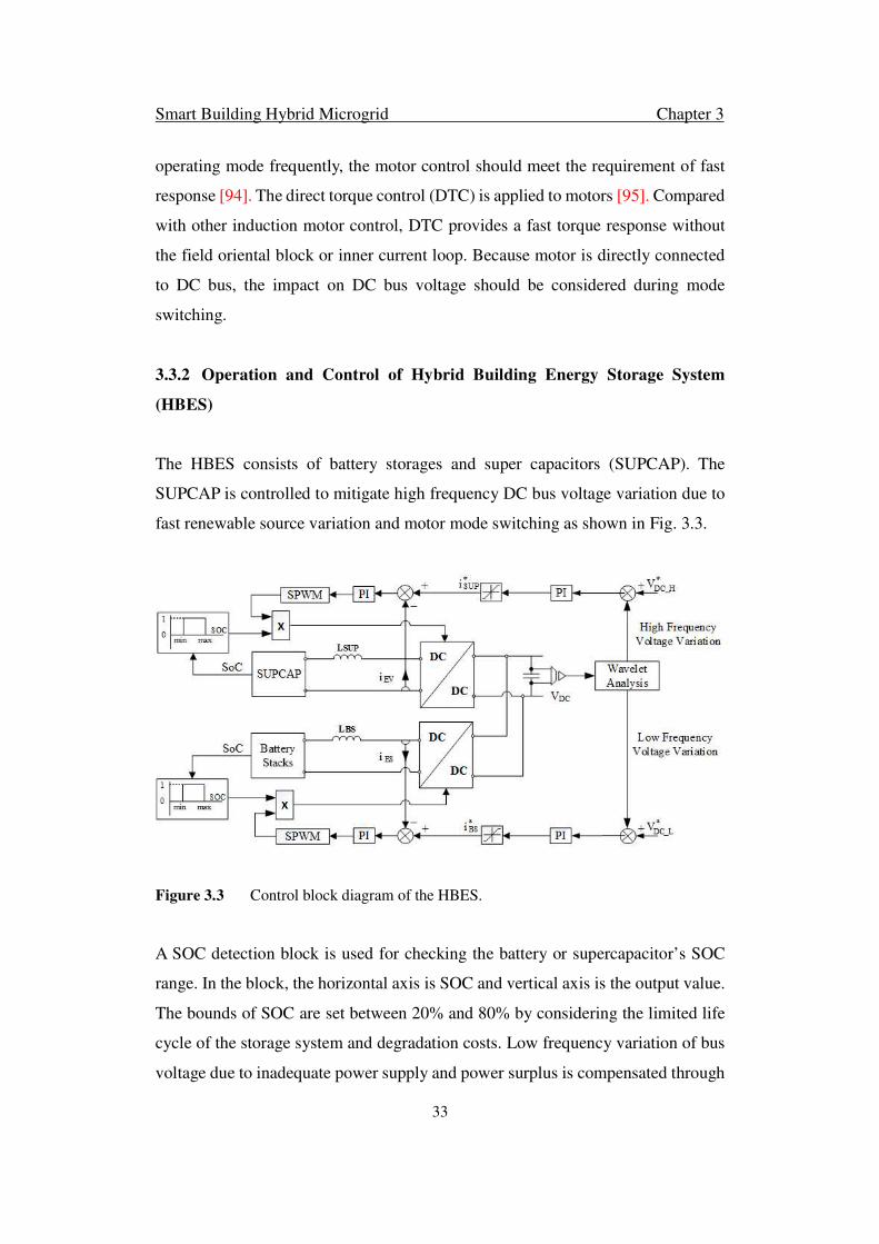
Smart Building Hybrid Microgrid Chapter 3
33
operating mode frequently, the motor control should meet the requirement of fast
response [94]. The direct torque control (DTC) is applied to motors [95]. Compared
with other induction motor control, DTC provides a fast torque response without
the field oriental block or inner current loop. Because motor is directly connected
to DC bus, the impact on DC bus voltage should be considered during mode
switching.
3.3.2 Operation and Control of Hybrid Building Energy Storage System
(HBES)
The HBES consists of battery storages and super capacitors (SUPCAP). The
SUPCAP is controlled to mitigate high frequency DC bus voltage variation due to
fast renewable source variation and motor mode switching as shown in Fig. 3.3.
Figure 3.3 Control block diagram of the HBES.
A SOC detection block is used for checking the battery or supercapacitor’s SOC
range. In the block, the horizontal axis is SOC and vertical axis is the output value.
The bounds of SOC are set between 20% and 80% by considering the limited life
cycle of the storage system and degradation costs. Low frequency variation of bus
voltage due to inadequate power supply and power surplus is compensated through

Smart Building Hybrid Microgrid Chapter 3
34
the charging and discharging of battery storage system. High and low frequency
components of DC bus voltage variation are decoupled by the wavelet analysis [96].
Wavelet analysis is used for decomposing HF and LF DC link voltage ripple. The
DC link voltage ripple can be expressed as:
K�L���� = M5NMOPQR�SPQRTU + M5NMOVP�SVPTU (3.3)
where C is the DC link capacitor; f is the ripple frequency; K. is the DC link voltage; KLWX8 is the supercapacitor terminal voltage; KLYW is the battery terminal voltage.
The ripple is the input of wavelet analysis block. The output of wavelet analysis
block can be expressed as:
K� & [ = /√] 2 2 ^M5NMOPQR�SPQRTU + M5NMOVP�SVPTU _.̀.̀ � �"Na] � 3- (3.4)
where a is positive and defines the scale and b is any real number and defines the
shift. HF and LF ripples are decomposed by defining the a and b.
3.3.3 Operation and Control of Building Photovoltaic System (BPVS)
The objective of BPVS is to harness the maximum power from sun. The control
strategy of BPVS converter is to track the maximum power point through regulating
the PV output voltage. The improved P&O algorithm with variable step has been
implemented in [97] for the maximum power point tracking (MPPT).
3.4 Coordination Control of BHMG
The main objectives of the BHMG operation and control are to maintain stable
AC/DC bus voltage, reduce building maximum demand and to achieve efficient
power utilization through minimizing DC/AC/DC and AC/DC/AC reverse
conversions. The coordination of different inverters and converters and the
bidirectional AC/DC converter plays an important role for stabilizing system

Smart Building Hybrid Microgrid Chapter 3
35
operation. Distributed control of individual converters is adopted to achieve the
defined control objectives. The BPVS is controlled to always operate in the MPPT
mode to harness the maximum energy from renewable sources. Motors in the
BMDS can operate either in the motor driving mode or in the regenerative braking
mode. The HBES is the core subsystem to be managed for reducing maximum load
demand and improving the system energy efficiency.
Figure 3.4 The schematic diagram of the compact BHMG.
When all subsystems are connected together, energy flow among them must
autonomously be managed to retain their overall high efficiency and reliability. The
bi-directional AC/DC converter is critical to manage power transfer between AC
and DC networks, which can be controlled to operate in any of the three modes:
Mode 0 with zero power transfer between AC and DC; Mode 1 with power transfer
from AC to DC; Mode 2 with power transfer from DC to AC. The amount of power

Smart Building Hybrid Microgrid Chapter 3
36
transferred between DC and AC sides are based on the SOC of the BHES and the
net power mismatch Pm between power generation and demand in DC side as
m BPVS BMDS LDCP P P P= + − (3.5)
where BPVSP is the BPVS output power, BMDS
P is the BMDS output power, and
LDCP is the total power of DC loads. If 0
mP = , bi-directional AC/DC converter
operates on mode 0; 0m
P < , bi-directional AC/DC converter operates on mode 1;
0m
P > , bi-directional AC/DC converter operates on mode 2.
A compact BHMG, which consists of a BPVS, BHES and a two-motor BMDS as
shown in Fig. 3.4, is used to illustrate the mode switching and control of converters
in a BHMG. The droop control is introduced to achieve the BHMG coordination
control.
3.4.1 Mode 0
When there is sufficient power from the BPVS and the HBES to supply DC demand,
the bidirectional AC/DC converter is not activated. The DC and AC networks
operate independently. In this case, the utility grid maintains AC bus voltage and
supplies AC loads.
Figure 3.5 DC side droop characteristic: (a) common DC bus droop characteristic; (b)
low voltage DC bus droop characteristic; (c) nominal droop characteristic.

Smart Building Hybrid Microgrid Chapter 3
37
The HBES converter operates in the voltage control mode to maintain voltage VDH
of the common DC bus. The bidirectional DC/DC converter is controlled to
maintain the voltage VDL of the low voltage DC bus through controlling the power
flow between two DC buses. The power flow direction and amount through
bidirectional DC/DC converter can be determined by common DC bus and low
voltage DC bus droop characteristic. Fig. 3.5 shows the droop characteristic in DC
side.
Fig. 3.5. (a) represents common DC bus droop characteristic and it is derived as:
_n DH DH DH DHV V d P= + ⋅ (3.6)
where VDH_n is reference common Dc bus voltage; dDH is droop coefficient; PDH is
required power at common DC bus.
Fig. 3.5. (b) represents low voltage DC bus droop characteristic and it is derived as:
_n DL DL DL DLV V d P= + ⋅ (3.7)
where VDL_n is reference common DC bus voltage; dDL is droop coefficient; PDL is
required power at low voltage DC bus.
Figure 3.6 Control block diagram of bidirectional DC/DC converter for mode 0.
In order to obtain the combine droop expression of common DC bus and low
voltage DC bus, a normalization method is used to merge the two variables VDH
and VDL in (3.6) and (3.7) into a same dimension.

Smart Building Hybrid Microgrid Chapter 3
38
( )
( )
'
_ max _ min
'
_ max _ min
10.5( )
10.5( )
DHDH DH
DH DH
DLDL DL
DL DL
dV P
V V
dV P
V V
= + ⋅−
= + ⋅−
(3.8)
By equation (4), the normalized value can be placed in the same frame of reference
with common vertical and horizontal axis as shown in Fig. 3.5. (c). Realization of
power flow between common DC bus and low voltage DC bus can then be inferred
by equalizing and through a PI controller.
[ ]= ( )' ( )' ( + )iDH DL DH DL p
kP V V k
s− − (3.9)
where PDH_DL is power flows on bidirectional DC/DC converter. The control block
diagram is shown in Fig. 3.6.
3.4.2 Mode 1
The BHMG operates in the power transfer modes when there is power surplus or
inadequate power supply under different load and resource conditions. The BMDS
at different modes require different active power and reactive power that affect the
power transfer direction between AC and DC sides. Since utility grid is connected
to AC bus, the AC side can be considered as an ideal source. The power flow
direction and amount are determined by DC side droop characteristic. DC side
droop characteristic integrates common DC bus droop characteristic and low
voltage DC bus droop characteristic. Fig. 3.7 shows the DC side characteristic.
The droop equation is developed as:
_n _ DH DH DC ACV V D P= + ⋅ (3.10)
1 1
1DH DL
d dD
+
= (3.11)

Smart Building Hybrid Microgrid Chapter 3
39
Figure 3.7 DC side droop characteristic when there is power transfer between AC and
DC sides.
When there is inadequate power supply from DC sources and the BHES is at the
minimum SOC, the bidirectional AC/DC converter operates in the rectifier mode
to partially or fully supply the DC loads and to maintain common DC bus voltage.
The active power is transferred from AC to DC. The operating point in Fig. 3.7 is
in the first phase (left). The low voltage DC bus is controlled by bidirectional
DC/DC converter and the common DC bus voltage is controlled by bidirectional
AC/DC converter. The control block diagram is shown in Fig. 3.8.
Figure 3.8 Control block diagram of bidirectional DC/DC converter for mode 1 & 2.

Smart Building Hybrid Microgrid Chapter 3
40
The bidirectional AC/DC converter control provides a smooth power exchange.
Power control is implemented by droop calculation and a PI controller for
bidirectional AC/DC converter to determine real power from AC to DC. Active
power change in common DC bus causes short time voltage fluctuation. The HBES
is operating to maintain common DC bus voltage.
3.4.3 Mode 2
When there is power surplus from DC side and the BHES is fully charged, the
bidirectional AC/DC converter is controlled to transfer power from DC to AC side.
In this case, the bi-directional AC/DC is activated to maintain the voltage of the
AC bus. The bi-directional DC/DC converter is used to maintain the voltage VDL of
the low voltage DC bus. The HBES converter is controlled to maintain a stable
voltage VDH of the common DC bus. The operating point in Fig. 3.7 is in the second
phase (right). The control block diagram is as same as Fig. 3.8. The common DC
bus voltage is controlled by charging and discharging of HBES.
3.5 Transit Analysis during Different Operation Modes
3.5.1 Mode 0
The time average equivalent circuit model of the converters in DC network is
shown in Fig. 3.9 and the control block diagram is shown in Fig. 3.10.
Figure 3.9 Time average model of the converters for the idle mode.

Smart Building Hybrid Microgrid Chapter 3
41
The BDCC controls the power flow between the CDCB and LDCB. If the power
from the BPVS is larger than the total load in the LDCB, the BDCC operates in the
booster mode to transfer power from LDCB to CDCB. Otherwise, the BDCC
operates in the buck mode to transfer power in opposite direction.
Figure 3.10 Control block diagram of the converter and BDCC in the idle mode.
LDCB voltage is controlled by the BDCC. The CDCB voltage EV is regulated by
the HBES converter. The differential equations for control and operation of BPVS
are as
11 1 1 1
1 1
1 1 2 2
(1 )
(1 )
S DC
SS
DC DC
DC
diV d V L R i
dt
dVi i C
dt
dV Vd i C i
dt Z
= − + +
= + − = + +
(3.12)
where 1d is the duty ratio of the PV converter, DC
Z is impedance of DC loads, SV
is PV output voltage, DCV is LDCB voltage, 1
i is the input current of the BPVS
converter, 2i is the input current of the BDCC, R1 and L1 are the resistance and
inductance of the BPVS converter respectively, and 2C is the equivalent
capacitance of LDCB.
The differential equations for control and operation of BDCC are as
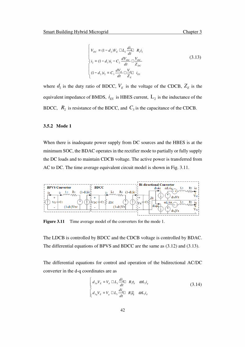
Smart Building Hybrid Microgrid Chapter 3
42
22 2 2 2
2 1 1 2
2 2 3
(1 )
(1 )
(1 )
DC E
DC DC
DC
E EES
E
diV d V L R i
dt
dV Vi d i C
dt Z
dV Vd i C i
dt Z
= − + +
= − − +
− = + +
(3.13)
where 2d is the duty ratio of BDCC, EV is the voltage of the CDCB, EZ is the
equivalent impedance of BMDS, ESi is HBES current, 2L is the inductance of the
BDCC, 2R is resistance of the BDCC, and 3C is the capacitance of the CDCB.
3.5.2 Mode 1
When there is inadequate power supply from DC sources and the HBES is at the
minimum SOC, the BDAC operates in the rectifier mode to partially or fully supply
the DC loads and to maintain CDCB voltage. The active power is transferred from
AC to DC. The time average equivalent circuit model is shown in Fig. 3.11.
Figure 3.11 Time average model of the converters for the mode 1.
The LDCB is controlled by BDCC and the CDCB voltage is controlled by BDAC.
The differential equations of BPVS and BDCC are the same as (3.12) and (3.13).
The differential equations for control and operation of the bidirectional AC/DC
converter in the d-q coordinates are as
3 3 3 3
3 3 3 3
dd E d d q
q
q E q q d
did V V L R i L i
dt
did V V L R i L i
dt
ω
ω
= + + − = + + +
(3.14)

Smart Building Hybrid Microgrid Chapter 3
43
where 3dd and 3qd are the duty ratio of the BDAC in d-q coordinates respectively,
dV and qV are the AC bus voltage in d-q coordinates respectively; di and
qi are
current in d-q coordinates respectively.
The control block diagram of the BDCC and BDAC based on the time average
equivalent circuit model is shown in Fig. 3.12.
Figure 3.12 Control block diagram of the converter and BDCC in mode 1.
These two converters provide a smooth power exchange. The power flow direction
is determined by ε. Power control is implemented by two PI controllers for the
BDAC to determine real power from AC to DC. Active power change in CDCB
causes voltage fluctuation. The active power transferred from AC to DC if the ε is
positive. In the BDAC power controller, the magnitude of *
di changes following the
changing of ε. In the inner current loop, di is tuned by regulating *
di .
3.5.3 Mode 2
When there is power surplus from DC side and the HBES is fully charged, the
BDAC is controlled to transfer power from DC to AC side. In this case, the BDAC
transfers power from DC to AC and to maintain the voltage of the AC bus. BDCC
maintains LDCB voltage. The time average equivalent circuit is shown in Fig. 3.13.

Smart Building Hybrid Microgrid Chapter 3
44
Figure 3.13 Time average model of the converters for the mode 2.
The HBES converter is controlled to maintain a stable CDCB voltage. The LDCB
voltage is controlled by BDCC. The differential equations for control and operation
of HBES are as
4 4 4
4 2 2 3(1 )
ESE ES ES
E EES AC
E
did V V L R i
dt
dV Vd i d i C i
dt Z
= + + = − − − −
(3.15)
where 4d is the duty ratio of HBES converter and ESV is the output voltage of the
HBES.
The AC bus voltage is regulated by the BDAC. The AC bus voltages in the d-q
coordinates are expressed as
3 3 3 3
3 3 3 3
dd d E d q
q
q q E q d
diV d V L R i L i
dt
diV d V L R i L i
dt
ω
ω
= − − + = − − −
(3.16)
The AC side currents in the d-q coordinates _AC di and
_AC qi are expressed as
_ 4
_ 4
dAC d d q
q
AC q q d
dVi i C V
dt
dVi i C V
dt
ω
ω
= + + = + +
(3.15)
The control block diagram of BHMG is shown in Fig. 3.14. Two dual loop PI
controllers are used in the BDAC to maintain stable AC bus voltage and control the
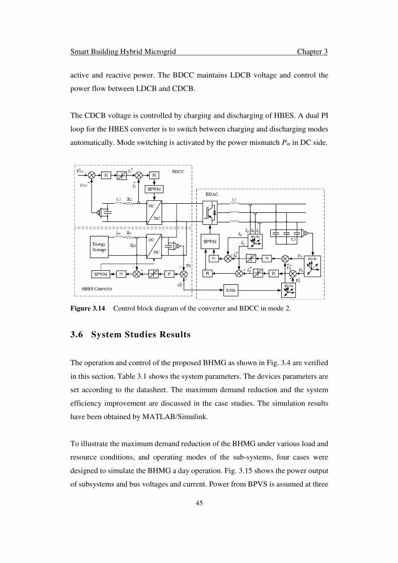
Smart Building Hybrid Microgrid Chapter 3
45
active and reactive power. The BDCC maintains LDCB voltage and control the
power flow between LDCB and CDCB.
The CDCB voltage is controlled by charging and discharging of HBES. A dual PI
loop for the HBES converter is to switch between charging and discharging modes
automatically. Mode switching is activated by the power mismatch Pm in DC side.
Figure 3.14 Control block diagram of the converter and BDCC in mode 2.
3.6 System Studies Results
The operation and control of the proposed BHMG as shown in Fig. 3.4 are verified
in this section. Table 3.1 shows the system parameters. The devices parameters are
set according to the datasheet. The maximum demand reduction and the system
efficiency improvement are discussed in the case studies. The simulation results
have been obtained by MATLAB/Simulink.
To illustrate the maximum demand reduction of the BHMG under various load and
resource conditions, and operating modes of the sub-systems, four cases were
designed to simulate the BHMG a day operation. Fig. 3.15 shows the power output
of subsystems and bus voltages and current. Power from BPVS is assumed at three

Smart Building Hybrid Microgrid Chapter 3
46
solar radiation levels. The BPVS output power rating is 15kW at high radiation
level, 10kW at medium radiation level and 1.5kW at low radiation level. The
occupier behavior determines the plug load demand. According to the building
operation profile [98], the load consuming power is assumed to be at three levels in
a day. Loads consume 15kW at high level, 10kW at medium level, and 2kW at low
level. Lift operation during a day has peak period and off-peak period. At peak
period, the lift usually travels round trip. Lift motors alternate between MDM and
RBM. Hence, BMDS consumes no power or regenerates power at peak period.
Motors under MDM usually occur at off-peak period.
Table 3.1 The parameters of the compact system
Symbol Quantity Value
PM Motor Power Rating 4 kW
Vn Motor Voltage Rating 460 V
f frequency 60 Hz
Ls Stator Inductance 0.3027 × 10⁻³ H
Lr Rotor Inductance 0.3027 × 10⁻³ H
Lm Mutual Inductance 10.46 × 10⁻³ H
Rs Stator Resistance 14.85 × 10⁻³ Ω
Rr Rotor Resistance 9.295 × 10⁻³ Ω
C1 BPVS Converter Capacitance 470 × 10−6 F
L1 BPVS Converter Inductance 3 × 10⁻³ H
R1 BPVS Converter Resistance 1 × 10⁻³ Ω
C2 BDCC Capacitance 2200 × 10−6 F
L2 BDCC Inductance 10 × 10−3 H
R2 BDCC Resistance 1 × 10⁻³ Ω
C3 BDAC Capacitance 470 × 10−6 F
L3 BDAC Inductance 3 × 10⁻³ H
R3 BDAC Resistance 1 × 10⁻³ Ω
L4 HBES Converter Inductance 10 × 10−3 H
R4 HBES Converter Resistance 1 × 10⁻³ Ω
VDC* LDCB Bus Reference Voltage 380 V
VE* CDCB Reference Voltage 640 V
VAC* AC Bus Voltage 220 V (rms)
Ll_AC AC Side line Inductance 0.1× 10⁻³ H
Rl_AC AC Side line Resistance 10× 10−3 Ω
Rl_DC DC Side line Resistance 0.5 Ω

Smart Building Hybrid Microgrid Chapter 3
47
Case 1: This case indicates the BHMG operation between 6 am to 10 am. The
simulation time is within 2.5s. The BPVS works at medium level to generate power
at 9932W. This is the peak period for lift operation system since it transfers the
building occupier frequently. The lift motor rating is set as 4kW and the motor
factor of maximum utilization is 0.75. In BMDS, one motor operates at MDM and
the other one operates at RBM. The BMDS just consumes 76W since the lack of
power conversion loss compensation. HBES discharge 295W to balance the system
power. The load of building consumes power at 9561W which consists of
fundamental loads 5kW at DC subgrid and plug loads at AC subgrid. The BDAC
operates at power transfer mode 2 to transfer 4786W from DC to AC subgrid.
Case 2: This case illustrates the BHMG operation between 10 am to 4 pm. The
simulation time is between 2.5s and 3.5s. The BPVS supply power of 14847W since
the solar radiation becomes stronger. The BMDS consumes 5946W at off-peak
period since two motors are at MDM. HBES discharges more power to supply the
whole system. More plug loads connect to the BHMG which make the load demand
increase to 14254W. The BDAC operates at power transfer mode 2 as well to
transfer 3863W from DC to AC subgrid.
Case 3: This case illustrates the BHMG operation between 4 pm to 8 pm. The
simulation time is between 3.5s and 4.5s. The BPVS operates at medium level to
generate 7762W. The BMDS regenerates 5374W at peak period since two motors
are at RBM. Plug loads decrease and load power consumption is reduced to
11328W. The HBES charges at 2051W in this case. The BDAC transfers more
power to supply the loads on AC side.
Case 4: This case illustrates the BHMG operation between 8 pm to 6 am. The
simulation time is beyond 4.5s. The BPVS works at low level to generate 1314kW
because of the PV energy storage. Loads of building only consume 1759W to
maintain the basic operation, which is set at DC subgrid. The BMDS consumes
power at 2035W since only one motor is operating. The HBES discharge power at

Smart Building Hybrid Microgrid Chapter 3
48
Figure 3.15 Operating performance of BHMG: (a) Power from the BPVS; (b) Power
consumed by loads; (c) Power of the BMDS; (d) Power from the HBES; (e) Power of the
BDAC; (f) LDCB voltage; (g) CDCB voltage; (h) AC bus voltage and current; (i) AC bus
transition voltage and current at 2.5s; (j) AC bus transition voltage and current at 3.5s.
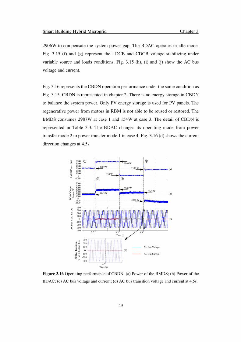
Smart Building Hybrid Microgrid Chapter 3
49
2906W to compensate the system power gap. The BDAC operates in idle mode.
Fig. 3.15 (f) and (g) represent the LDCB and CDCB voltage stabilizing under
variable source and loads conditions. Fig. 3.15 (h), (i) and (j) show the AC bus
voltage and current.
Fig. 3.16 represents the CBDN operation performance under the same condition as
Fig. 3.15. CBDN is represented in chapter 2. There is no energy storage in CBDN
to balance the system power. Only PV energy storage is used for PV panels. The
regenerative power from motors in RBM is not able to be reused or restored. The
BMDS consumes 2987W at case 1 and 154W at case 3. The detail of CBDN is
represented in Table 3.3. The BDAC changes its operating mode from power
transfer mode 2 to power transfer mode 1 in case 4. Fig. 3.16 (d) shows the current
direction changes at 4.5s.
2987 W
5946 W
154 W
2535 W (a)
①
② ③
④
BM
DS
Pow
er
(W)
Time (s)
300
0
200
100
-100
-200
-300
-400
400
(c)
AC
Bus
V (
V)
& I
(A
)
AC
Bus
Tra
nsit
ion
V (
V)
& I
(A
) at 4.5
s 300
0
200
100
-100
-200
-300
(d)
2.5 3.5 4.5
Time (s)
AC Bus Voltage
AC Bus Current
60007000
50004000300020001000
0BD
AC
Outp
ut
Pow
er
(W)
(b)1945 W
3901 W
2608W
-1512 W-1000-2000
4.5
600050004000300020001000
0-1000
Figure 3.16 Operating performance of CBDN: (a) Power of the BMDS; (b) Power of the
BDAC; (c) AC bus voltage and current; (d) AC bus transition voltage and current at 4.5s.
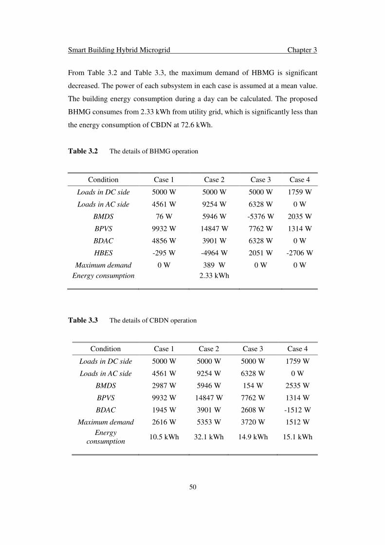
Smart Building Hybrid Microgrid Chapter 3
50
From Table 3.2 and Table 3.3, the maximum demand of HBMG is significant
decreased. The power of each subsystem in each case is assumed at a mean value.
The building energy consumption during a day can be calculated. The proposed
BHMG consumes from 2.33 kWh from utility grid, which is significantly less than
the energy consumption of CBDN at 72.6 kWh.
Table 3.2 The details of BHMG operation
Condition Case 1 Case 2 Case 3 Case 4
Loads in DC side 5000 W 5000 W 5000 W 1759 W
Loads in AC side 4561 W 9254 W 6328 W 0 W
BMDS 76 W 5946 W -5376 W 2035 W
BPVS 9932 W 14847 W 7762 W 1314 W
BDAC 4856 W 3901 W 6328 W 0 W
HBES -295 W -4964 W 2051 W -2706 W
Maximum demand 0 W 389 W 0 W 0 W
Energy consumption
2.33 kWh
Table 3.3 The details of CBDN operation
Condition Case 1 Case 2 Case 3 Case 4
Loads in DC side 5000 W 5000 W 5000 W 1759 W
Loads in AC side 4561 W 9254 W 6328 W 0 W
BMDS 2987 W 5946 W 154 W 2535 W
BPVS 9932 W 14847 W 7762 W 1314 W
BDAC 1945 W 3901 W 2608 W -1512 W
Maximum demand 2616 W 5353 W 3720 W 1512 W
Energy
consumption
10.5 kWh
32.1 kWh
14.9 kWh
15.1 kWh

Smart Building Hybrid Microgrid Chapter 3
51
3.7 Summary
A novel building hybrid microgrid is proposed in this chapter to reduce building
power demand and energy consumption, to improve building energy utilization
efficiency and to simplify building distribution network. Under various load and
resource conditions, the BHMG can maintain reliable operation. The simulation
results show that the BMDS, BPVS and HBES can smoothly change operating
mode. AC/DC bus voltages are stable under different operating conditions and
during modes switching. The power can transfer smoothly between AC and DC and
between LDCB and CDCB. The duration of the grid-tied operation and power input
from utility grid has been reduced. The building maximum demand and energy
consumption have been significantly reduced using the energy storage and direct
power exchange through CDCB. Therefore, it can be concluded that the CDCB and
LDCB network architecture is more efficient topology for power exchange among
motors in driving and regenerating modes and therefore can significantly reduce
multiple reverse conversions in CBDN. A hybrid building energy storage system
(HBES) can provide cost-efficient solutions for different operation problems. The
succeeded work will still focus on how to further improve the building microgrid
efficiency. The controller for each subsystem can be improved. For the BDMS, a
novel approach integrating elevator operating optimization and motor control will
be proposed for further use the regenerative energy among the motor drives. In the
HBES, adaptive area droop control will be proposed for automatically switch the
energy storage operating mode by changing the droop coefficient and to achieve
the coordination control between battery and supercapacitor. Moreover, the
centralized control will be introduced in building microgrid to further reduced
maximum demand. These improvements for each subsystem will be introduced in
the following chapters.

Smart Building Hybrid Microgrid Chapter 3
52

Distributed Lift Operation Control Chapter 4
53
Chapter 4
Distributed Lift Operating Control in Smart Building Hybrid
Microgrid
In this chapter, a novel control approach which integrates optimal
operation and direct torque control (DTC) for motors in building
hybrid microgrid is introduced. The optimal control and operation of
lifts is based on fuzzy logic which uses the real time data inputs such as
original level, destination level, call level, etc. DTC is used in motor
controllers. The fuzzy PID controller in DTC is designed to achieve a
smaller overshoot and faster response compared with the conventional
PID controller. The proposed control approach is verified through
simulations.
*This section published substantially as D. Zhu, P. Wang, X. Han, W. Qin, “Distributed Lift
Operating Control in Building Lift System”. IEEE International Conference on Information and
Automation, ICIA 2015, Yunnan, China, Aug 8-10, 2015.

Distributed Lift Operation Control Chapter 4
54
4.1 Introduction
With growing population, cities become more crowded. To achieve efficient land
use, more high-rise and multi-story buildings appear in mega cities. To reduce
building energy consumption is important in improving building energy utilization
efficiency. In a high rise commercial building, lift motors not only consume energy
but also can regenerate energy. A building lift system is proposed to classify and
integrate all lifts together to improve building energy utilization efficiency.
A novel distributed lift control approach based on fuzzy logic and DTC is proposed
in this chapter to integrate lift operating optimization and motor control. Lift
operating optimization method is based on the fuzzy logic. The inputs of the fuzzy
logic-based optimization are real time call level, original level and destination level,
which are more related with the real lifts operation. The motor controller is
designed based on DTC. A fuzzy self-tuning method is introduced in motor
controller. The proportional and integral gains in controller can be self-tuning
according to the lift operation. The novel approach is set for each motor in building
lift system. By using this method, the peak power demand can be reduced.
4.2 Lift Control System
The distributed lift operating controller consists of three parts: operating
optimization, selector and motor controller. Fig. 4.1 shows the overall control block.
The objective of operating optimization is to choose the lift which gives a better
quality of occupants’ journey experience and consume less or regenerate more
power. The core part of optimization is advanced fuzzy controller. Compared with
conventional fuzzy controller, advanced fuzzy controller has one more layer to
process the input signal. The selector is a comparator to determine whether the lift
is operating.
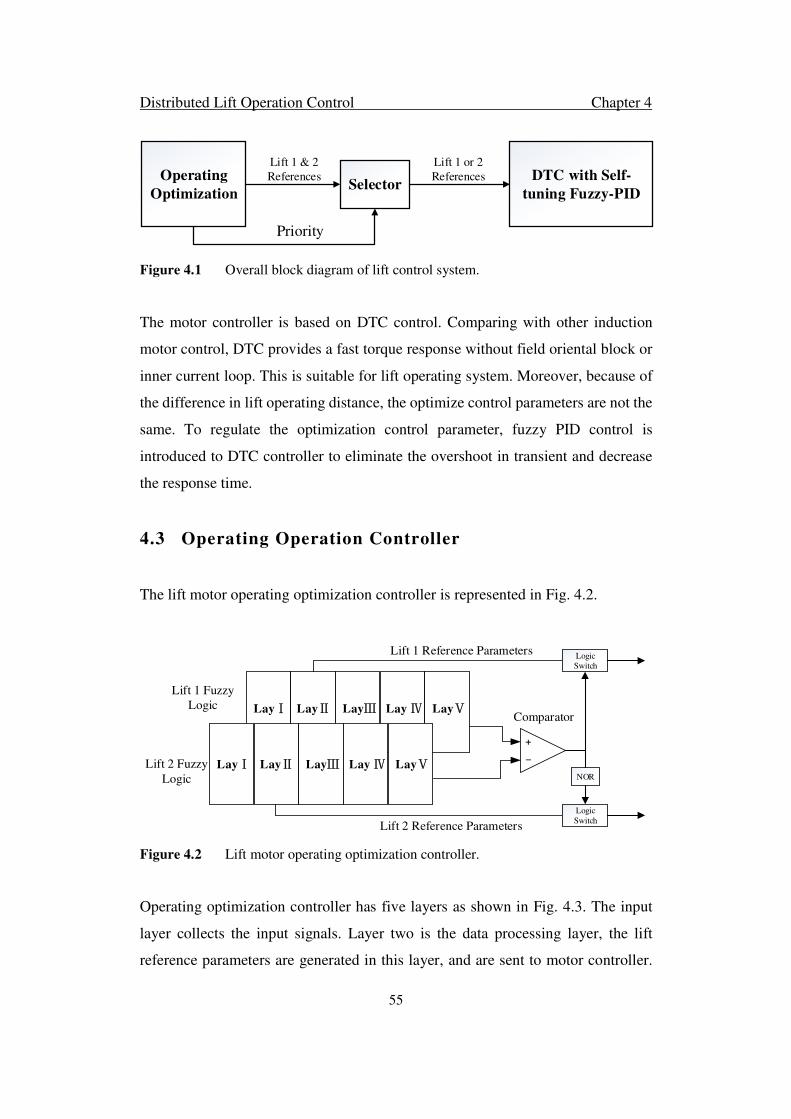
Distributed Lift Operation Control Chapter 4
55
Operating
OptimizationSelector
DTC with Self-
tuning Fuzzy-PID
Lift 1 & 2
References
Lift 1 or 2
References
Priority
Figure 4.1 Overall block diagram of lift control system.
The motor controller is based on DTC control. Comparing with other induction
motor control, DTC provides a fast torque response without field oriental block or
inner current loop. This is suitable for lift operating system. Moreover, because of
the difference in lift operating distance, the optimize control parameters are not the
same. To regulate the optimization control parameter, fuzzy PID control is
introduced to DTC controller to eliminate the overshoot in transient and decrease
the response time.
4.3 Operating Operation Controller
The lift motor operating optimization controller is represented in Fig. 4.2.
LayⅠ LayⅡ LayⅢ Lay Ⅳ LayⅤ
LayⅠ LayⅡ LayⅢ Lay Ⅳ LayⅤ
+
_
Comparator
Lift 1 Fuzzy
Logic
Lift 2 Fuzzy
Logic
Logic
Switch
Logic
Switch
NOR
Lift 1 Reference Parameters
Lift 2 Reference Parameters
Figure 4.2 Lift motor operating optimization controller.
Operating optimization controller has five layers as shown in Fig. 4.3. The input
layer collects the input signals. Layer two is the data processing layer, the lift
reference parameters are generated in this layer, and are sent to motor controller.

Distributed Lift Operation Control Chapter 4
56
Fuzzy logic output comes from layer five. The output form the output layer is a
value between zero and one. In a building lift system with two lift motors, the fuzzy
logic has two outputs for the selector to determine which lift to deliver the
passengers.
1
1
2
3
I
I
I
O1
1O
2
1O
3
1O
4
µ (e) NL
µ (e) NL
µ (e) ZE
µ (e) PL
µ (e) ZE
µ (e) PL
∏
∏
∏
∏
∏
∏
∑
.
.
.
.
.
.
.
.
.
.
.
.
Op
LayⅡ LayⅢ Lay ⅣLayⅠ LayⅤ
Figure 4.3 Detailed description of fuzzy logic layers.
4.3.1 Layer I
This layer is the input layer. Conventional inputs are waiting time, riding time, etc.
However, in reality, the input signals are only at call level, original level and
destination level. The call level is where the passenger waits. The original level is
at which the lift parks before the passenger press the button. Destination level is the
level the passenger wants to go. In layer II, these three signals are used to calculate
the waiting time, riding time, etc.

Distributed Lift Operation Control Chapter 4
57
4.3.2 Layer II
This layer is the data processing layer. Define 1I as the call level; 2I as the original
level; 3I as the destination level. Use these three parameters to calculate 1
1O ,1
2O , 1
3O ,
1
4O , where 1
1O is waiting time; 1
2O is riding time; 1
3O is crowed degree; 1
4O is power
consumption.
Equation (4.1) shows the waiting time calculation.
1
1
1 2
W n
n
W
S VO
V a
S I I H
= + = − ×
(4.1)
where SW is the operating distance from the original level to call level, H is the
height of each level, Vn is operating speed of an accelerator.
In lift operating system, operating speed and accelerator are essential parameters.
If the speed is too high, passengers in lift car feel uncomfortable. If the speed is too
low, time will be wasted in the lift. Moreover, different speeds have relative
accelerators. Through a look-up table, different speeds are chosen by different
distances. The look-up table is provided by lift manufactory. Hitachi VFH-II model
is chosen in this chapter.
As it is in the waiting time calculation, equation (4.2) shows the riding time
calculation.
1
2
3 1
nR
n
R
VSO
V a
S I I H
= + = − ×
(4.2)
where SR is the operating distance from the call level to destination level.
In lift operating optimization, waiting time and riding time are most important.
However, constraints are not only confined by these two parameters. Suppose the
lift is full, the lift will not stop at call level. The priority of an empty lift is higher

Distributed Lift Operation Control Chapter 4
58
than a full lift. Hence, under this assumption, crowded degree is another essential
parameter.
Equation (4.3) shows the crowded degree calculation.
1
3
m ax
mO
M= (4.3)
where m is the weight of the car. Mmax is the maximum weight of the car.
The other parameter is power consumption. Equation (4.4) shows the power
consumption calculation.
( )( )
++=
⋅−−==
⋅+==
−=
∫∫
∫∫
22
2
2
22
2
14
)(r
er
rsr
sloss
losserrmGG
lossemrmMM
GM
P
TR
M
LR
M
RP
dtPTdtPW
dtPTdtPW
WWO
ϕϕ
ω
ω (4.4)
where WM is the energy consumed by motor, and WG is the energy generated by lift
in regenerative mode, Ploss is the power loss in motor, Tem is the electromagnetic
torque when motor is at motor mode, Ter is the electromagnetic torque when motor
is at regenerative mode, Rs is stator resistance, M is the mutual inductance, Lr is the
rotor inductance; P is pole number. 1
1O , 1
2O , 1
3O , 1
4O are regarded as input signals to
next layer.
4.3.3 Layer III
This is the fuzzification layer. Each input signal from layer two is fuzzified by
membership functions. Each input consists of three parts: negative large (NL), zero
(ZE) and positive large (PL). For each input, three membership functions are
chosen for different parts. Membership functions are based on sigmoid function
and triangle function.
Equation (4.5) shows the sigmoid function.

Distributed Lift Operation Control Chapter 4
59
( ))(1
1,;
bxaebaxsigy −−+
== (4.5)
where parameter a is weight value. It determines the curve slope. Parameter a is
larger; the curve slope is steeper. Parameter b is threshold value; it determines the
center point of the curve. Sigmoid function is appropriate for representing concepts
such as “NL” or “PL”.
Equation (4.6) shows the triangle function.
0
(x; , , )
0
x
xx
y trianglex
x
x
αα α β
β αα β χ
χ β χχ β
χ
, ≤ − , < ≤
−= = − , < ≤
− , <
(4.6)
Fuzzification process by membership functions are described by equation (4.7).
( )
( )
( )
( )
( )
1 1 .max1 1 .max
1 1
1 1 .max .max .max
1 1 .max1 1 .max
1 1 .max2 2 .max
1 1
2 2 .max .max
3( ; , )
8 10 8
1 1 3( ; , , )
4 2 4
5( ; , )
8 10 8
3( ; , )
8 10 8
1 1( ; ,
4 2
NL WW
ZE
W W W
PL WW
NL rr
ZE
r r
TO sig O T
O triangle O T T T
TO sig O T
TO sig O T
O triangle O T T
µ
µ
µ
µ
µ
− = × = = ×
−=×
=
( )( )( )( )( )
( )
.max
1 1 .max2 2 .max
1 1
3 3
1 1
3 3
1 1
3 3
1 1
4 4
1 1
4 4
3, )4
5( ; , )
8 10 8
( ; 0.01, 0.4)
( ; 0.3, 0.5, 0.7)
( ; 0.01, 0.6)
5( ; , )
24 10 12
1 1 2( ; , ,
3 2 3
r
PL rr
NL
ZE
PL
NL
ZE
T
TO sig O T
O sig O
O triangle O
O sig O
WO sig O W
O triangle O W W
µ
µ
µ
µ
µ
µ
= ×
= − =
=
−=×
=
( )( )
1 1
4 4
min max
)
7( ; , )
24 10 12
PL
W
WO sig O W
W W W
µ
= × = +
(4.7)

Distributed Lift Operation Control Chapter 4
60
where .maxWT is the maximum waiting time passengers can endure, .maxrT is the
maximum riding time passengers can endure, minW is the motor maximum
regenerative power, since it is negative, it can be regarded as minimum power
consumption of motor, maxW is the maximum power consumption of motor. The
calculation results are sent to the next layer to do the rule process.
4.3.4 Layer IV
This is the fuzzy rule process layer. The data from layer III will be sent to the fuzzy
rule base. Each data is converted to a value through base rule base. Sum all the
value and send the results to the next layer.
4.3.5 Layer V
This is the output layer. The fuzzy logic output is sent to the motor controller. The
output is a value between 0 and 1. The value represents priority. The motor with
higher priority is operating. When a motor in building lift system is operating and
a new request is sent to the controller, the controller in each motor will calculate
again based on the real time condition.
4.4 Motor Controller
The direct torque control (DTC) is introduced into lift motor since lift changes the
operating mode frequently. The motor with DTC can meet the requirement of fast
response. Compared with other induction motor control, DTC provides a fast torque
response without field oriental block or inner current loop. Fig. 4.4 shows the
control block diagram of motor controller.
Flux and Torque Estimation block could be described by equation (4.8).
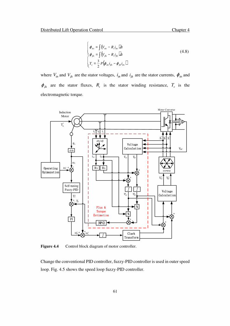
Distributed Lift Operation Control Chapter 4
61
( )( )( )
−=
−=
−=
∫
∫
sssse
ssss
ssss
iiPT
dtiRV
dtiRV
αββα
βββ
ααα
ϕϕ
ϕ
ϕ
2
3
(4.8)
where sVα and sVβ are the stator voltages, siα and siβ are the stator currents, sαϕ and
sβϕ are the stator fluxes, sR is the stator winding resistance, eT is the
electromagnetic torque.
abc/αβ
ia ib ic
SVPWM
Sa* Sb
* Sc*
d/dt
θr
Self-tuning
Fuzzy-PID
ωr
Induction
Motor
Motor Converter
+ -ωr*
Voltage Calculation
Rs Rs
iαs iβs Vαs Vβs
+
+
-
-
∫ ∫ψαs
ψβs
X
X
Te*
+ -3P/2
+- Te
PI
∫+ωsl +* ωs
* Clark Transform
Voltage Calculation
+
+
-
-
Vαs Vβs* *
Flux & Torque
Estimation
VDC
Operating Opimazation
TL
*
Figure 4.4 Control block diagram of motor controller.
Change the conventional PID controller, fuzzy-PID controller is used in outer speed
loop. Fig. 4.5 shows the speed loop fuzzy-PID controller.

Distributed Lift Operation Control Chapter 4
62
The following equation (4.9) is a mathematic description.
+=
+=
+=
++= ∫
dfdd
ifii
pfpp
dipe
KKK
KKK
KKK
dt
deKedtKeKT
αα
α
*
*
*
****
(4.9)
where α is weight, Kpf, Kif and Kdf are tuning parameters from fuzzy logic. In these
equations, four parameters are working independently. These parameters cannot
affect each other. They increase the tuning accuracy.
Fuzzifier Rule Base Difuzzifier
Kp
Ki
Kd
X
X
X
∫
d/dt
ωr
ωr*
Te*
α
Kpf
K if
Kdf
++
++
+
+
+
+
+
+
_
Figure 4.5 Speed loop Fuzzy-PID controller.
4.5 System Studies
The simulation model of building lift system is based on compact model in Fig. 4.6.
Using MATLAB/SIMULINK to simulate passenger lift system operation.
Assume a building has 100 floors, the call level is the first floor, and destination
level is 30 floor. Motor one stays at 10 floor, motor two stays at 20 floor. When the
passenger pushes the button at the first floor, the operating optimization controller
starts to calculate, and sends the results to motor controller. Fig. 4.7 shows the
priorities from two operating optimization controller.

Distributed Lift Operation Control Chapter 4
63
SUPCAP
Induction
Motor
Res Les
Induction
Motor
Passenger Elevator
System
Figure 4.6 Compact Model of Passenger Lift System.
Figure 4.7 Optimal scheduling results of building lift system.
From the Fig. 4.7, the priority of motor 1 is higher than motor 2. It means motor 1
starts operating and motor 2 remain stationary. Fig. 4.8 shows the two motors
operating performance.
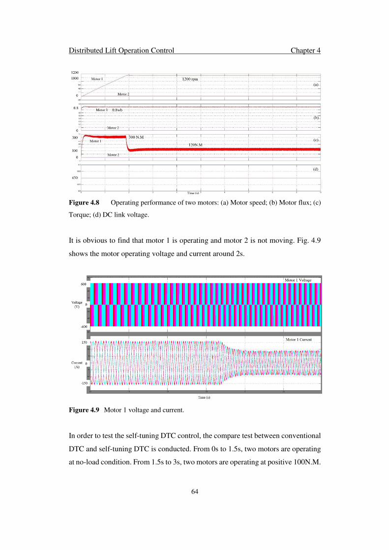
Distributed Lift Operation Control Chapter 4
64
Figure 4.8 Operating performance of two motors: (a) Motor speed; (b) Motor flux; (c)
Torque; (d) DC link voltage.
It is obvious to find that motor 1 is operating and motor 2 is not moving. Fig. 4.9
shows the motor operating voltage and current around 2s.
Figure 4.9 Motor 1 voltage and current.
In order to test the self-tuning DTC control, the compare test between conventional
DTC and self-tuning DTC is conducted. From 0s to 1.5s, two motors are operating
at no-load condition. From 1.5s to 3s, two motors are operating at positive 100N.M.
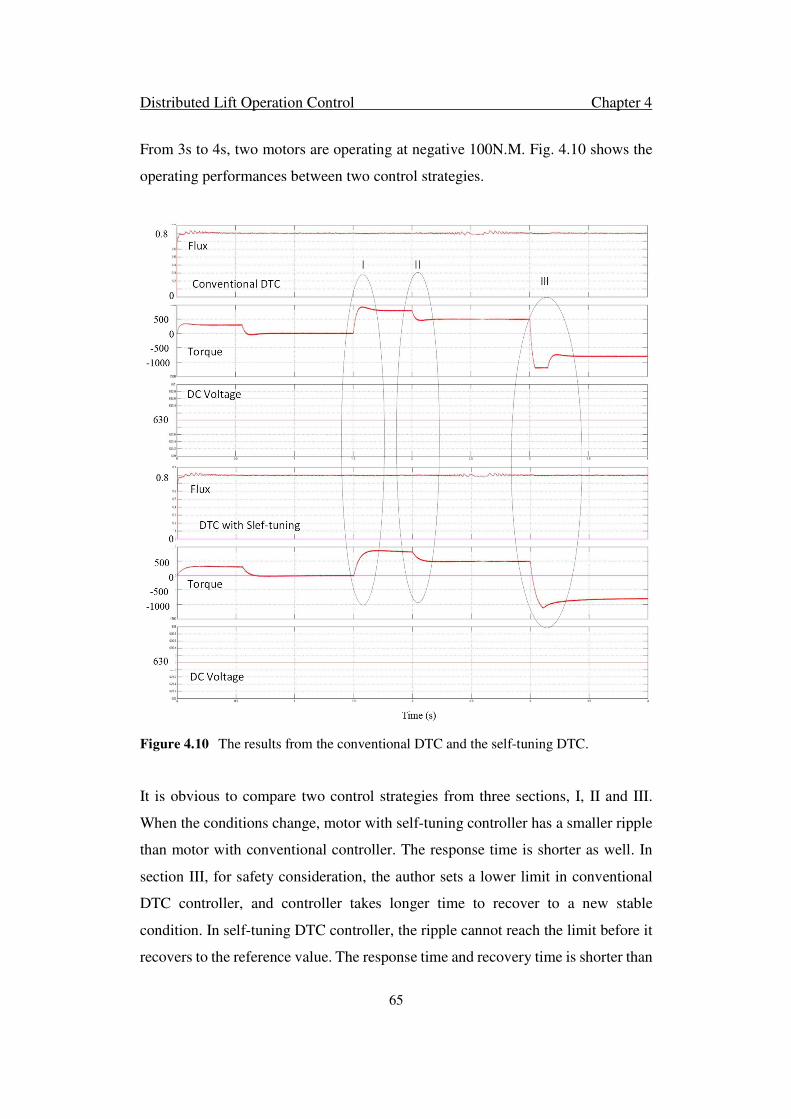
Distributed Lift Operation Control Chapter 4
65
From 3s to 4s, two motors are operating at negative 100N.M. Fig. 4.10 shows the
operating performances between two control strategies.
Figure 4.10 The results from the conventional DTC and the self-tuning DTC.
It is obvious to compare two control strategies from three sections, I, II and III.
When the conditions change, motor with self-tuning controller has a smaller ripple
than motor with conventional controller. The response time is shorter as well. In
section III, for safety consideration, the author sets a lower limit in conventional
DTC controller, and controller takes longer time to recover to a new stable
condition. In self-tuning DTC controller, the ripple cannot reach the limit before it
recovers to the reference value. The response time and recovery time is shorter than

Distributed Lift Operation Control Chapter 4
66
conventional method. Therefore, the motor with self-tuning controller is more
stable than the conventional controller.
4.6 Summary
A novel lift control approach is proposed in this chapter. Evaluation of novel
control method is investigated. The detailed control algorithm is introduced. Model
established by MATLAB/Simulink is designed to test the validation of novel
control. The results show the novel lift control can choose a more proper lift to
operate. This lift control system ensures shorter waiting time and riding time. It
consumes less power, it can even regenerate power and dump it back into SUPCAP.
The motor controller with self-tuning has a smaller ripple and shorter response and
recovery time. By this method, the power efficiency in high rise multi story building
can be improved. The other subsystem in building hybrid microgrid, hybrid energy
storage system, is modified in the next chapter.

Adaptive Area Droop Control Chapter 5
67
Chapter 5
Adaptive Area Droop Control for Hybrid Energy Storage
System in Building Hybrid Microgrid
To reduce the complexity of power management and enforce coincident
control strategy of distributed energy storages for individual PV
systems and lift systems in a smart building microgrid, a centralized
hybrid building energy storage system (HBES) is proposed to serve
multiple functions such as energy buffer and power balancer. The
objective is to reduce the building maximum power demand under the
minimum system marginal cost. HBES consists of a battery bank with
high energy density as auxiliary storage and a super capacitor bank
with high power density as priority storage. An adaptive area droop
controller is designed to switch HBES automatically from voltage
regulation mode to power control mode by changing the droop
coefficient. A coordination control is proposed for battery and
supercapacitor in HBES. The proposed adaptive area droop controller
is verified through simulations and experiments.
*This section published substantially as D. Zhu, P. Wang, “Adaptive Area Droop Control for Hybrid
Energy Storage System in Building Microgrid”. IEEE Transactions on Industrial Electronics, under
review.
Adaptive Area Droop Control Chapter 5
68
5.1 Introduction
Compared to the utility grid, converter-based microgrids have low rotational inertia
which makes the microgrids unstable under particular operating conditions. Energy
storages introduce equivalent inertia into microgrids and enhance dynamic stability
against loads or changing of renewable power sources [99]. In building microgrid,
Energy storages for renewable power sources such as photovoltaic (PV) power
source require high energy density. Nevertheless, loads with high-pulse power
requirement such as portable electric devices and electric vehicles require energy
storages with high power density. Therefore, hybrid energy storage system (HESS)
which consists of both high energy density storages like battery and high power
density storage like supercapacitor is proposed to meet the aforementioned
requirements in building microgrid [100].
In this chapter, study system configuration is introduced first. Based on this
configuration, hybrid building energy storage system (HBES) has different
operating modes. The proposed adaptive area droop control is introduced to HBES
which could automatically change the energy storage operating mode by changing
the droop coefficient. Then, the coordination control of hybrid energy storage
system is investigated which gives the activation criterial of battery and
supercapacitor.
5.2 Building System Configuration
5.2.1 System Configuration
The system configuration is shown in Fig. 5. 1. The system is a two-level four-
subsystem configuration, which is proposed for easy and efficient integration of
various DC links in the motor driving circuits, DC energy storages, DC loads and
PV systems.
Adaptive Area Droop Control Chapter 5
69
A common DC bus is proposed to integrate all motors through DC/AC converters,
which eliminates the AC/DC rectifiers of motor driving circuits connecting to the
AC bus [101]. To simplify the complex connection of distributed energy storages
in different buses, hybrid energy storage system is proposed to be connected to
common DC bus. Hybrid energy storage system works as a central energy buffer
not only to balance the power gap caused by motor drives, but also to balance the
entire system power gap caused by PV and load change. Building PV system is a
renewable energy source and connected to low voltage DC bus. Loads are placed
at common DC bus or low voltage DC bus according to their voltage requirements.
Figure 5.1 Building system configuration.
5.2.2 Hybrid Energy Storage System Operating Modes
Batteries are widely used as energy buffers to compensate the building power gap
caused by PV and load change. PV output power is related to solar radiation curve
and the variation frequency is low. Some kinds of loads in buildings such as lighting
system also have low frequency variation characteristic. Batteries with high energy
density balance the entire system’s power under low frequency variation.
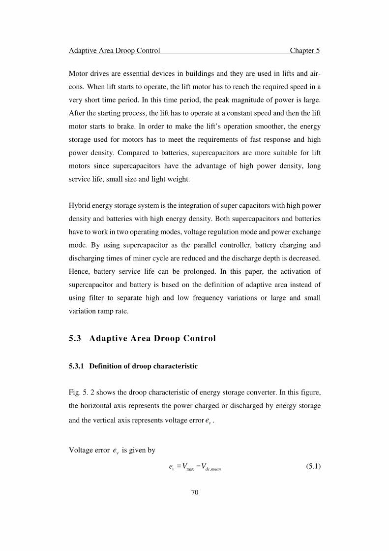
Adaptive Area Droop Control Chapter 5
70
Motor drives are essential devices in buildings and they are used in lifts and air-
cons. When lift starts to operate, the lift motor has to reach the required speed in a
very short time period. In this time period, the peak magnitude of power is large.
After the starting process, the lift has to operate at a constant speed and then the lift
motor starts to brake. In order to make the lift’s operation smoother, the energy
storage used for motors has to meet the requirements of fast response and high
power density. Compared to batteries, supercapacitors are more suitable for lift
motors since supercapacitors have the advantage of high power density, long
service life, small size and light weight.
Hybrid energy storage system is the integration of super capacitors with high power
density and batteries with high energy density. Both supercapacitors and batteries
have to work in two operating modes, voltage regulation mode and power exchange
mode. By using supercapacitor as the parallel controller, battery charging and
discharging times of miner cycle are reduced and the discharge depth is decreased.
Hence, battery service life can be prolonged. In this paper, the activation of
supercapacitor and battery is based on the definition of adaptive area instead of
using filter to separate high and low frequency variations or large and small
variation ramp rate.
5.3 Adaptive Area Droop Control
5.3.1 Definition of droop characteristic
Fig. 5. 2 shows the droop characteristic of energy storage converter. In this figure,
the horizontal axis represents the power charged or discharged by energy storage
and the vertical axis represents voltage error ve .
Voltage error ve is given by
max ,v dc meane V V= − (5.1)

Adaptive Area Droop Control Chapter 5
71
where Vmax is the maximum allowable CDCB voltage which is a constant value
usually set as ten percent plus the reference bus voltage; Vdc,mean is the mean value
of real-time DC bus voltage. Vdc,mean is calculated by maximum and minimum
values. In [102], the mean value calculator implementation in controller is
introduced. The double frequency ripple in output voltage is eliminated by using
the mean value calculator. Moreover, the controller has a high bandwidth compared
to conventional controller using real time sensed voltage.
Figure 5.2 Droop characteristic definition.
The red line represents the droop curve which is given by
max _s i droop v sP k P k e= − (5.2)
where Pmax is determined by the energy storage manufacturer which is the power
tolerance while operating; for safety consideration, ki is a parameter to scale the
maximum power; kdroop is the droop coefficient.
The blue line represents the load curve which is given by
max _( )s dc v sP I V e= − (5.3)
where Ps is the power charged or discharged from energy storage to balance the
system power; Idc is the value of CDCB current injected into or out of the energy
storage converter; _v se is the bus voltage error at operating point. According to the

Adaptive Area Droop Control Chapter 5
72
figure, the load curve is changing in two phases. In the right phase, the CDCB
current injects into converter and energy storage operates in charging mode. Idc is
positive. In the left phase, the CDCB current is dumped out from converter and
energy storage operates in discharging mode. Idc is negative. The blue line with
arrow in the figure represents the current decrease direction.
The operating point (O.P) of energy storage is the intersection between load and
droop curve. The meaning of operating point is that, if the CDCB voltage has a
voltage variation , the energy storage should charge or discharge power Ps to
maintain the voltage and make the system operating properly. In the figure, the
operating point is in the right phase, the energy storages is charged the surplus
power when the CDCB voltage error is , which means PV and loads power do
not balance.
5.3.2 Voltage regulation
The basic requirement for building microgrid proper operation is to ensure each bus
voltage is stable in the system. Energy storages in the HESS are working as an
energy buffer which can regulate bus voltage. Fig. 5.3 illustrates the adaptive droop
control for voltage regulation.
The nominal CDCB voltage *V is derived as subtracting nominal CDCB voltage
error _0ve by Vmax. In order to achieve a stable bus voltage, the nominal CDCB
voltage error _0ve which is determined by operating point has to be a constant value.
In the other word, moves alone a vertical line. In Fig. 5. 3, moving curve
is a dotted horizontal line. In order to place the intersection point alone the
moving curve, the droop coefficient has to be modified adaptively. By equating
(5.2) and (5.3), the droop coefficient is derived as
_v se
_v se
_ 0ve _ 0ve
_ 0ve
Adaptive Area Droop Control Chapter 5
73
max maxi dcdroop dc
v
k P I Vk I
e
−= − (5.4)
Equation (5.4) represents kdroop is a function of CDCB voltage and CDCB current
injected to energy storage converter. This controller is able to regulate the bus
voltage. However, for hybrid energy storage system controller, voltage regulation
is not the only control objective. Power exchange control is needed for the power
transfer between energy storages and microgrid.
Figure 5.3 Voltage regulation droop control.
5.3.3 Power exchange
When large variation of energy storage output power occurs, power exchange
control of energy storage will be activated to fast compensate the power gap.
Moreover, for some extreme conditions like sudden change in load demand or
reconnection of power generation to the grid, the energy storage need to respond
quickly to balance the grid energy which requires energy storage to charge or
discharge fast. Fig. 5.4 illustrates the adaptive droop control for power control.

Adaptive Area Droop Control Chapter 5
74
Figure 5.4 Power exchange droop control.
The reference charging or discharging power Ps is introduced into droop control to
achieve the fast power balance requirement and it is determined by the energy
storage power rating. In Fig. 5.4, Ps moving curve is a vertical dotted line. The
operating point has to move alone the Ps moving curve. By equating (5.2) and (5.3),
the droop coefficient is derived as
max
max
i sdroop
s
dc
k P Pk
PV
I
−=−
(5.5)
The equation also represents the droop coefficient as a function of Vmax and Idc.
In the figure, two conditions are presented for energy storage charge and discharge.
If building PV system’s output power is larger than loads requirement, the surplus
power has to be absorbed. argch e
sP is set for the energy storage fast charging.
Operating point 1 has to move alone the moving curve. If building PV
system is not able to supply the loads, argdisch e
sP is set for the energy storage fast
discharging. Operating point 2 has to be placed on the argdisch e
sP moving curve.
argch e
sP

Adaptive Area Droop Control Chapter 5
75
This controller is advantageous for power balance in the system which is able to
fast charging and discharging. However, this control approach cannot control the
bus voltage. If the voltage error related with intersection point is far from the
nominal voltage error, the bus voltage is unstable which makes the system to
breakdown. Therefore, there should be a trade-off between voltage regulation and
power exchange control.
5.3.4 Adaptive droop area control
Adaptive area droop control integrates voltage regulation and power exchange. Fig.
5. 5 represents the definition of adaptive area.
A bus voltage error tolerance is set when the energy storage converter controller is
operating and this error tolerance does not affect the microgrid operating stability.
The error tolerance is defined as the ve range around the nominal CDCB voltage
error . The lower limitation is _ minve and the upper limitation is _ maxve . In this
research, the range from _ minve and _ maxve is 10V. These two parameters determine
the voltage error edges of adaptive area.
Figure 5.5 Definition of adaptive area.
_ 0ve

Adaptive Area Droop Control Chapter 5
76
A charging and discharging power tolerance is set according to the energy storage
power rating, which means the charging or discharging power also has the upper
limitation _ maxsP and lower limitation _minsP . The chosen of and for
supercapacitor converters is based on the motor characteristic since the
supercapacitors are used for the high frequency power variation caused by motors.
The _ min
SUP
sP and _ max
SUP
sP of supercapacitor converters are set as
*
_ min
*
_ max
2 2 2
2 2 2
2 *
2 2 2
2 2
2 2 2 2
( )
( )
( )
21 ( )
21 ( )
SUP
s m regen
SUP
s m regen
s r rregen r
m r
s rr r r
m r
s r s rr r
m r m
P P P
P N P P
R L JP R
L p
R L DR J
L p
R L RDR D
L p L
ωϕ
ω ωϕ
ϕωϕ
= −
= ⋅ + = − +
− + +
− + + −
(5.6)
where N is the number of motors in building system; *
mP is the motor rating power;
regenP is the motor regenerative power.
The and for battery converters are determined by PV and loads
operation since the batteries are used to compensate the whole system power gap.
The _ min
BAT
sP and _ max
BAT
sP of battery converters are set as
_ min _ max _ min
_ max _ min _ max
BAT
s pv load
BAT
s pv load
P P P
P P P
= −
= −
(5.7)
where _minpvP and _ maxpvP are the PV maximum and minimum output power
respectively; _minloadP and _ maxloadP are the maximum and minimum load power
respectively.
These two power limitation parameters determine the power exchange edges of
adaptive area.
_ maxsP _ minsP
_ maxsP
_ minsP

Adaptive Area Droop Control Chapter 5
77
Two cases are designed when the energy storage converter with adaptive area droop
control is operating. One is that, after sudden change, the operating point is still in
the adaptive area. The other is when the operating point is out of the adaptive area
after sudden change. In order to clearly show the case study, only the adaptive area
in right phase is represented. The theory of adaptive area droop control in the left
phase is the same as that in the right phase.
Case 1: The operating point is still in the adaptive area after sudden change. This
case usually happens when the load is slightly change or partial motors change the
operating modes. The regenerated energy from motors can be consumed by other
motors or local loads. The CDCB voltage varies slightly. In building microgrid, the
motor drive used for lifts changes the operating mode frequently. The
supercapacitor is used for compensating the high frequency power variation and the
battery does not need to respond to the variation. Fig. 5.6 illustrates this condition
and the red dotted line investigates the battery converter operating point moving
direction.
Figure 5.6 Battery converter operating point changing in the adaptive area (Idc decrease
condition).
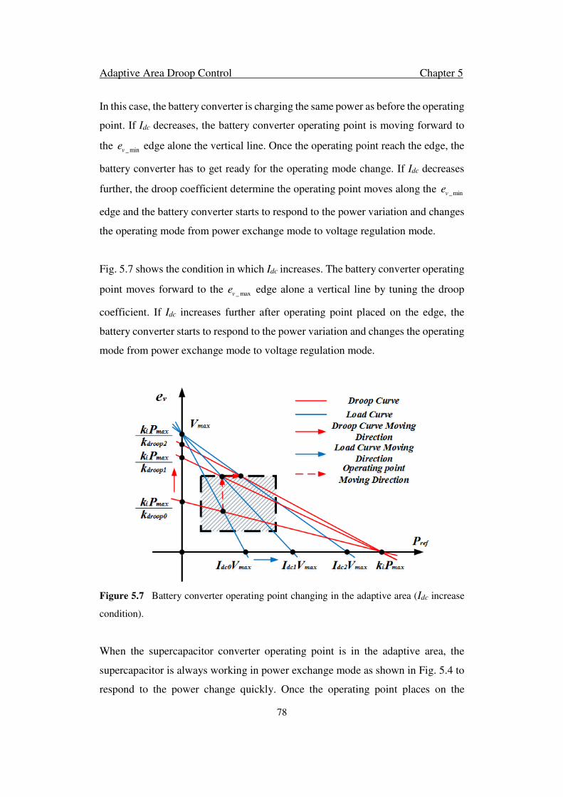
Adaptive Area Droop Control Chapter 5
78
In this case, the battery converter is charging the same power as before the operating
point. If Idc decreases, the battery converter operating point is moving forward to
the _ minve edge alone the vertical line. Once the operating point reach the edge, the
battery converter has to get ready for the operating mode change. If Idc decreases
further, the droop coefficient determine the operating point moves along the _ minve
edge and the battery converter starts to respond to the power variation and changes
the operating mode from power exchange mode to voltage regulation mode.
Fig. 5.7 shows the condition in which Idc increases. The battery converter operating
point moves forward to the _ maxve edge alone a vertical line by tuning the droop
coefficient. If Idc increases further after operating point placed on the edge, the
battery converter starts to respond to the power variation and changes the operating
mode from power exchange mode to voltage regulation mode.
Figure 5.7 Battery converter operating point changing in the adaptive area (Idc increase
condition).
When the supercapacitor converter operating point is in the adaptive area, the
supercapacitor is always working in power exchange mode as shown in Fig. 5.4 to
respond to the power change quickly. Once the operating point places on the

Adaptive Area Droop Control Chapter 5
79
voltage error edges, and further changes in the voltage error disallow the system to
work properly, the supercapacitor converter starts to work for the voltage regulation.
Case 2: The operating point is out of the adaptive area after sudden change. This
case usually happens in three conditions. First is when the energy storage converter
starts working. The initial operating point is outside the adaptive area. In order to
avoid this condition, the droop coefficient has to be tuned before the controller
starts working. Second condition is when motors are under starting procedure or
large loads change suddenly. The motor’s starting current is four times higher than
the rating current and it will cause large bus voltage variation. Under this condition,
the battery and supercapacitor converters operating points are out of the voltage
error edges. Last condition is when most motors change operating modes, the
supercapacitors take fast response after motors mode change and the supercapacitor
converter’s operating point is out the power exchange edges.
Figure 5.8 Operating point out of the adaptive area (O.P place on ve edge).
Both battery and supercapacitor controllers are tuning the droop coefficient first
which let the operating point move alone the load curve and place on the edge of
the adaptive area. If the operating point is placed on the voltage error edge, the
battery converter starts working on voltage regulation mode and makes the
operating point move alone the voltage error edge. The supercapacitor converter

Adaptive Area Droop Control Chapter 5
80
gets ready to work in power exchange mode. If the operating point is changing in
the adaptive area, battery is charging the same power as the operating point placed
on the voltage error edge. The supercapacitor is always working in power exchange
mode as case 1 to fast response the power change. Fig. 5.8 represents this condition
and the red dotted line investigates the battery converter operating point moving
direction.
Fig. 5.9 shows the condition when the operating point places on the power exchange
edge after moving alone the load curve. The supercapacitor converter is working
on power exchange mode. The battery controller is still tuning the droop coefficient
to the point related reference voltage error. Then the battery is working in voltage
regulation mode.
Figure 5.9 Operating point out of the adaptive area (O.P place on sP edge).
Adaptive area droop controller with these two designed cases offers instant action
during transient by increasing the response speed of the controller. Moreover, it is
able to improve the stability of energy storage converter.
Adaptive Area Droop Control Chapter 5
81
5.3.5 Steady-State and Dynamic Analysis of the Proposed Controller
Adaptive area droop controller has to be demonstrated with stable performance
before it can be used for hybrid energy storage system. For steady-state analysis,
the O.P is located in the adaptive area, and the bus voltage has to be stable. The
steady-state CDCB voltage _dc sV derived from equations (5.1), (5.2) and (5.3) as
max max
_
droop i
dc s
droop dc
k V k PV
k I
−=
− (5.8)
It is obvious to find that the steady state DC bus voltage depends on droop
coefficient, DC bus current and system parameters. The criterion of droop
coefficient depends on the existence of O.P. Therefore, two conditions are
considered. Either of them is able to guarantee the O.P excising.
Condition 1:
max max
maxmax
i dc
i
droop
k P I V
k PV
k
> >
Condition 2:
max max
maxmax
i dc
i
droop
k P I V
k PV
k
< <
Condition 1 is used to design the droop coefficient since the DC bus current can be
zero. The droop coefficient has to make sure all the operating conditions are taken
into consideration. Then, the system is stable at steady-state if the droop coefficient
reaches the requirement in equation (5.9)
max max
maxmax
i dc
i
droop
k P I V
k PV
k
> >
(5.9)
For dynamic analysis, the dynamic equation of CDCB voltage is derived. The
transient performance of DC bus voltage is estimated according to the fast state
Adaptive Area Droop Control Chapter 5
82
variables which should be able to reach the steady-state variables. Considering the
time period as 2 tω , the CDCB voltage is able to be written as
( )2
1dcconv dc
dc t
dVi i
dt C ω
= −
(5.10)
where dcC is DC bus capacitance; convi is the output current of converter. Insert the
equations (5.2) and (5.3), the dynamic equation (5.8) is written as
max maxi droop droop dc dcdc
dc
k P k V k V IdV
dt C
− − −= (5.11)
The eigenvalue of dynamic equation (5.11) is calculated as
droop
dc
k
Cλ = − (5.12)
The value of dcC is positive. If the system is stable, the droop coefficient has to be
positive. Based on the steady-state and dynamic analysis, the system is operating
properly by choosing the proper droop coefficient.
5.4 Coordination Control of HESS
Coordination control based on the adaptive area droop control is used to maintain
the HESS and stable operation of building hybrid microgrid. The coordination
control logic diagram is shown in Fig. 5. 10.
At the HESS level, operation modes of the individual converter are determined by
operating point positions in droop characteristic. Operating point detection is based
on the adaptive area definition which is introduced in Fig. 5.5. At local level, the
individual converter operating mode are based on commends from HESS level, the
individual energy storage constraints and the charging/discharging rate of energy
storages in HESS. The energy storage constraints of battery or supercapacitor are
determined according to the state of charge (SOC) which is described as

Adaptive Area Droop Control Chapter 5
83
min maxSOC SOC SOC≤ ≤ . The battery and supercapacitor have to work in power
exchange mode when the SOC is below the lower limit. Moreover, the battery has
to charge or discharge a constant amount of power when the operating point is in
the adaptive area but not on the voltage error edges. The battery is not activated
when the power change is in the adaptive area. For the other cases, battery has to
work in the voltage regulation mode to maintain the CDCB voltage. Supercapacitor
has to operate in voltage regulation mode to assist battery to maintain the voltage
when the operating point is moving along the voltage error edges or in the adaptive
area. In these cases, supercapacitors are ready for power exchange mode to fast
respond to the power variation.
Figure 5.10 Control mode diagram of energy storage converters.

Adaptive Area Droop Control Chapter 5
84
Based on Fig. 5.10, the control scheme diagram is represented in Fig. 5.11. Multi-
loop droop controller is used for both battery and supercapacitor converters. This
control scheme is applied for HESS in building microgrid to provide a stable CDCB
voltage in building microgrid and fast power exchange between HESS and
microgrid. During operating scenario change, the control objective can be changed
automatically by tuning the droop coefficient.
Figure 5.11 Control mode diagram of energy storage converters.
5.5 System Studies
The simulation results are presented in this section for adaptive area droop
controller in this paper. The simulation results have been obtained by
MATLAB/Simulink. TABLE 5.1 shows the parameters used for the simulations.
The devices parameters are set according to the datasheet.

Adaptive Area Droop Control Chapter 5
85
Table 5.1 The parameters of the simulation implementation
Symbol Quantity Value
Vmax Maximum CDCB Voltage 520 V
Vn Nominal CDCB Voltage 500 V
ev_o Nominal CDCB Voltage Error 20 V
ev_max Maximum CDCB Voltage Error 25 V
ev_min Minimum CDCB Voltage Error 15 V
_max
BAT
sP Maximum Battery Converter
Power Tolerance
2500 W
_min
BAT
sP Minimum Battery Converter
Power Tolerance
100 W
_max
SUP
sP Maximum Supercapacitor
Converter Power Tolerance
6000 W
_min
SUP
sP Minimum Supercapacitor
Converter Power Tolerance
100 W
L HESS Converter Inductance 1.8 × 10⁻³ H
R HESS Converter Equivalent
Resistance 1 × 10⁻³ Ω
C HESS Capacitance 20 × 10−6 F
Cdc CDCB Capacitance 470 × 10−6 F
Fig. 5.12 represents the condition when the operating point is still in the adaptive
area after a sudden change. At the initial state, the operating point is at the nominal
voltage. The battery supplies 1000W to compensate the power gap between PV and
loads. At 1.2s, the load suddenly changes, which makes the CDCB voltage drop to
496V. The operating point is still in the adaptive area. The battery holds its
operating mode and supplies the same amount of power as at the initial state. The
supercapacitor is working at voltage regulation mode to balance the power change.
The supercapacitor responds quickly to the load change and follows the load
recovery. At around 1.8s, the load is recovered and the supercapacitor is at reverse
charging mode. After 1.9s, the voltage is back to the nominal value of 500V.
Fig. 5.13 shows the condition in which the operating point is out of the adaptive
area after a sudden change. In the initial state, the operating point is at the nominal
voltage and battery supplies 1000W. At 1.2s, the CDCB voltage drops to 490V
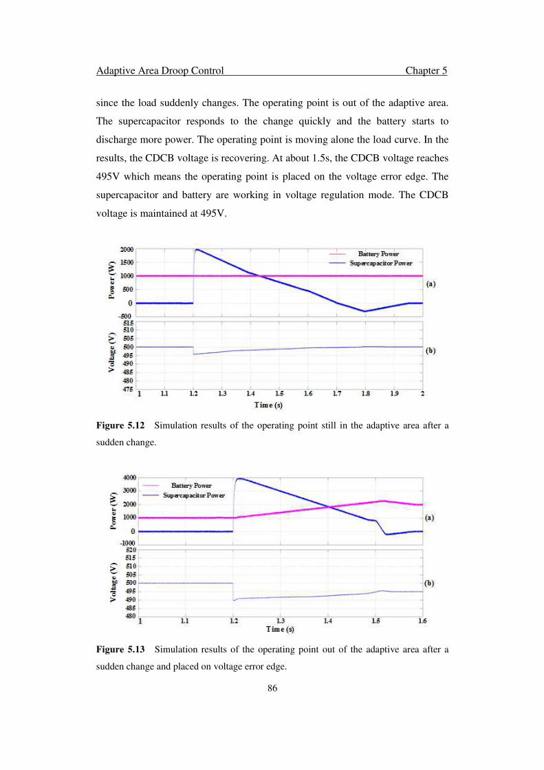
Adaptive Area Droop Control Chapter 5
86
since the load suddenly changes. The operating point is out of the adaptive area.
The supercapacitor responds to the change quickly and the battery starts to
discharge more power. The operating point is moving alone the load curve. In the
results, the CDCB voltage is recovering. At about 1.5s, the CDCB voltage reaches
495V which means the operating point is placed on the voltage error edge. The
supercapacitor and battery are working in voltage regulation mode. The CDCB
voltage is maintained at 495V.
Figure 5.12 Simulation results of the operating point still in the adaptive area after a
sudden change.
Figure 5.13 Simulation results of the operating point out of the adaptive area after a
sudden change and placed on voltage error edge.

Adaptive Area Droop Control Chapter 5
87
Fig. 5.14 illustrates the operating point placed on the power exchange edge after a
sudden change. In the initial state, the operating point is at the nominal voltage and
battery supplies 1500W. At 1.2s, the CDCB voltage drops to 486V since the sudden
large load change. The supercapacitor fast response but it reaches the maximum
power limitation 6000W and the supercapacitor supplies 5914W in a short time
period. With the load slowly recovers and battery discharges, the supercapacitor
discharge power decreases. Between 1.36s to 1.49s, the battery discharge power
reaches the maximum and supplies 2448W. In this period, the supercapacitor ends
discharge and starts to reverse charge. The ramp rate of voltage recovery is reduced.
At 1.66s, the voltage is back to the nominal value of 500V and the battery supplies
the power gap as the initial state.
Figure 5.14 Simulation results of the operating point out of the adaptive area after a
sudden load change and placed on power exchange edge.
5.6 Summary
An adaptive area droop control approach has been proposed in this chapter, which
demonstrates an automatic mode change and stable operating performance for
energy storage converters in HESS. The proposed control method is based on droop
control and integrates voltage regulation and power exchange control. The voltage

Adaptive Area Droop Control Chapter 5
88
regulation is able to regulate a bus voltage to a constant value by tuning the droop
coefficient. This is well-suited for energy storage converter where a constant bus
voltage is required. The power exchange control can enable fast power exchange
between energy storage and building microgrid. Moreover, adaptive area droop
control is designed for battery and supercapacitor in HESS. The coordination
control is introduced in HESS which reduces the battery charging and discharging
times of miner cycle and discharge depth. Hence, the battery service time is also
prolonged.
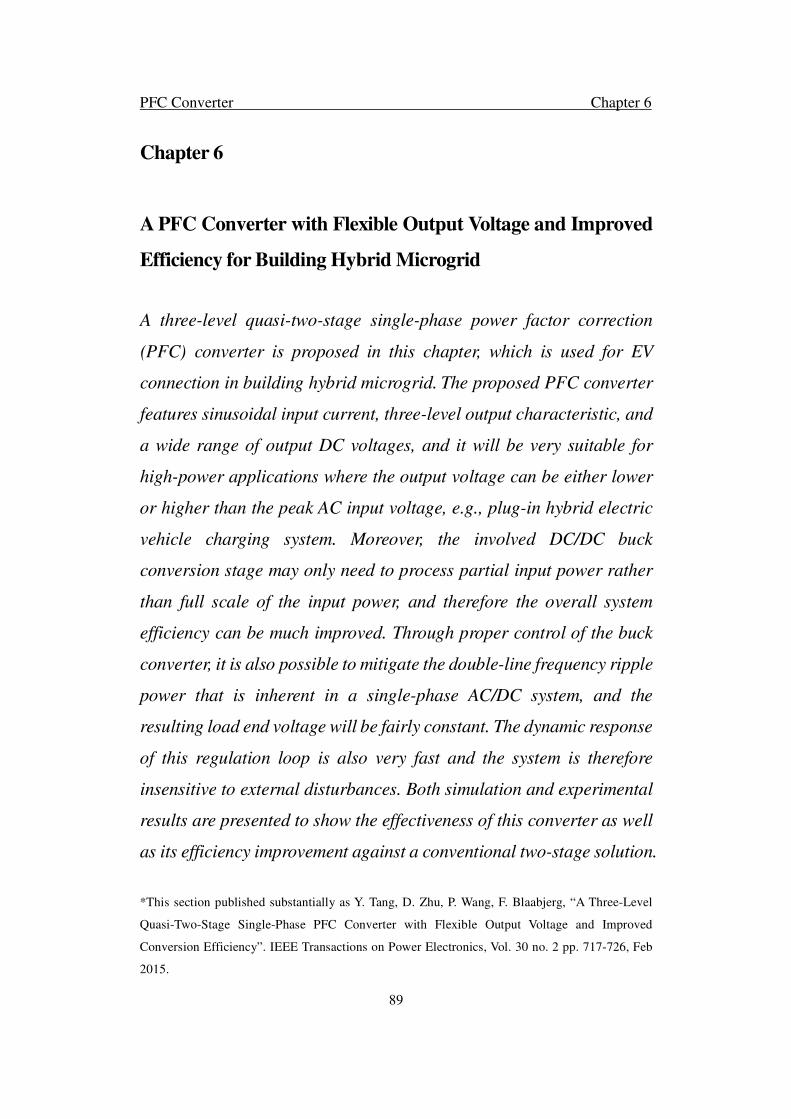
PFC Converter Chapter 6
89
Chapter 6
A PFC Converter with Flexible Output Voltage and Improved
Efficiency for Building Hybrid Microgrid
A three-level quasi-two-stage single-phase power factor correction
(PFC) converter is proposed in this chapter, which is used for EV
connection in building hybrid microgrid. The proposed PFC converter
features sinusoidal input current, three-level output characteristic, and
a wide range of output DC voltages, and it will be very suitable for
high-power applications where the output voltage can be either lower
or higher than the peak AC input voltage, e.g., plug-in hybrid electric
vehicle charging system. Moreover, the involved DC/DC buck
conversion stage may only need to process partial input power rather
than full scale of the input power, and therefore the overall system
efficiency can be much improved. Through proper control of the buck
converter, it is also possible to mitigate the double-line frequency ripple
power that is inherent in a single-phase AC/DC system, and the
resulting load end voltage will be fairly constant. The dynamic response
of this regulation loop is also very fast and the system is therefore
insensitive to external disturbances. Both simulation and experimental
results are presented to show the effectiveness of this converter as well
as its efficiency improvement against a conventional two-stage solution.
*This section published substantially as Y. Tang, D. Zhu, P. Wang, F. Blaabjerg, “A Three-Level
Quasi-Two-Stage Single-Phase PFC Converter with Flexible Output Voltage and Improved
Conversion Efficiency”. IEEE Transactions on Power Electronics, Vol. 30 no. 2 pp. 717-726, Feb
2015.

PFC Converter Chapter 6
90
6.1 Introduction
Plug-in hybrid electric vehicle (PHEV) is gaining popularity in today's automotive
market due to increasing concerns on environment and sustainable development.
Because of its hybrid propulsion nature, a battery storage system must be equipped
inside, which can be recharged from the utility electrical grid through an AC/DC
converter with power factor correction (PFC) function [103].
Battery chargers supplied by single-phase AC mains are usually rated below 5kW
and the most commonly used topologies for front-end AC/DC conversion are the
simple boost type PFC converter and the full bridge rectifier. Nevertheless, these
two topologies are both of boost type and can only produce a DC voltage that is
higher than the peak AC input voltage (greater than 325V for 230V grid). In order
to cater for variable voltage levels of the battery pack (50V-600V) [104], a second
stage DC/DC buck converter has to be implemented to step down the PFC output
voltage, which undoubtedly decreases system overall efficiency.
To provide a simple but effective solution, this chapter presents a high efficiency
single-phase PFC converter that features sinusoidal input current, three-level output
characteristic and flexible output DC voltage. Its attractiveness is that the embedded
bidirectional DC/DC buck converter may only need to process partial input power
rather than full scale of input power, and therefore its conversion efficiency can be
much improved compared with the conventional two stage solution. Also, the PFC
stage exhibits three-level output voltage, and the dV/dt across the switches are
reduced, so as the swishing losses. An added benefit of this converter is that, the
fluctuating 100Hz or 120Hz harmonic power in the single-phase system can be
almost diverted into the DC-link capacitor through proper control design, and the
terminal voltage and/or the charging current of battery pack will be fairly constant,
which may expand its working lifetime. Its operation principle and control
strategies are discussed in details in this paper, and both simulation and
experimental results are provided for validation.

PFC Converter Chapter 6
91
6.2 Converter Description and the Operation Principle
The circuit diagram of the proposed single-phase AC/DC converter is shown in Fig.
6.1, which consists of a standard diode bridge, a three-level PFC, and a bidirectional
DC/DC converter. In the case that V2G support is needed, the diode bridge can be
replaced by an unfolding bridge and the diodes of the PFC stage should be replaced
by MOSFETs or IGBTs with anti-parallel diode so that active power can be
reversely converted from the battery pack to the utility grid. As shown in Fig. 6.1,
the rechargeable battery pack is directly connected to the output of the three-level
PFC, and it is also interconnected with the high voltage DC bus through the
bidirectional DC/DC converter. This high voltage DC bus may also serve as the
DC-link of a three-phase inverter that is usually used to drive a rear-end traction
motor.
Figure 6.1 Circuit diagram of proposed three-level PFC converter for single-phase
PHEV chargers.
As mentioned previously, the proposed three-level PFC has a wide range of output
voltages and it can function as either a buck or a boost converter. During the boost
operation, there are two operation modes for Q1 and Q2. When the low DC bus
voltage or simply the load voltage VL is higher than the instantaneous input voltage
Vin |sinωt|, where Vin is the peak value of input voltage and ω is the fundamental
angular frequency, Q2 will be always on. Q1 and D1 then form up a standard boost

PFC Converter Chapter 6
92
PFC that directly converts input power for DC load consumption, and the converter
pole voltage VAB will be changed between 0 and VL .In order to realize the PFC
function, the duty cycle of Q1 should comply with
1
| sin |1 in
L
V td
V
ω= − (6.1)
which is the basic equation for a boost PFC. It should be noted that, in this operation
period, the buck converter does not need to process any input power as they are all
directly supplied into the battery through this PFC converter.
In second operation interval when VL is less than Vin|sinωt|, Q1 remains off. Q2 and
D2 will modulate and form up another boost PFC. VAB is now changing between
VL and the high DC bus voltage VH. Again, to ensure sinusoidal input current and
unity power factor, the duty cycle of Q2 must comply with
2
| sin |1 in L
H L
V t Vd
V V
ω −= −−
(6.2)
Intuitively, when D2 is conducting, excessive input power will be flowing into the
DC-link capacitor CH and this high bus voltage will be subsequently stepped down
by the bidirectional DC/DC converter so as to charge the battery, and this is the
root reason that why the DC/DC converter only process partial input power and
higher conversion efficiency can be obtained.
In order to ensure smooth transition between low and high voltage level
commutations, an offset is injected into the carrier of pulse-width modulation
(PWM) for Q2 as shown in Fig. 6.2. As a result, a unified reference signal Vm can
be derived to simultaneously modulate Q1 and Q2, which is written as
| sin |1
( )| sin |
in
L
m
L in
H L
V t
Vv t
V V t
V V
ω
ω
−= − −
, | sin |
, | sin |
in L
in L
V t V
V t V
ω
ω
≤
> (6.3)

PFC Converter Chapter 6
93
Compared with the conventional boost PFC, the proposed converter has slightly
higher conduction losses because of the series connection of Q2 and D1. However,
its switching losses can be greatly reduced due to its three-level characteristic that
splits the high DC bus voltage into two portions. Moreover, efficiency gain from
the DC/DC converter is also significant because it only converts the input power
that flow through D2.
Figure 6.2 Idealized operating waveforms for proposed three-level PFC converter.
To estimate the percentage of input power λ that is converted by this buck stage, it
is assumed that the power converter is lossless and harmonic free. In this case, the
instantaneous input power from AC side will be
| sin | | sin | (1 cos 2 )2
in inin in in
V Ip V t I t tω ω ω= ⋅ = − (6.4)
where Iin is the peak value of boost inductor current.
If the PFC is commutating at high voltage levels, part of input power will be directly
supplied into the battery when Q2 is on, and can be found as

PFC Converter Chapter 6
94
_ 2| sin |
| sin || sin | 1
| sin || sin |
batt H in L
in Lin L
H L
H inL in
H L
p I t d V
V t VI t V
V V
V V tV I t
V V
ω
ωω
ωω
= ⋅ ⋅
−= − −
−= −
(6.5)
Plotting (6.4) and (6.5) will give rise to the time domain waveforms of power
distribution shown in Fig. 3, and it is clear that the shaded area enclosed by pin and
pbatt_H indicates the power pdc that needs to be processed by the buck converter.
Figure 6.3 Instantaneous power distribution in PFC converter and buck converter, given
fixed gird voltage, output voltage, and dc-link voltage.
Taking the integration of pin and pdc over half fundamental period, it is possible to
find that

PFC Converter Chapter 6
95
( )
( )
arcsin( / )
_arcsin( / )
0
arcsin( / )
arcsin( / )
0
arcsin( / )
2arcsin( / )
0
| sin | 1
(1 cos 2 )2
| sin || sin |
L in
L in
L in
L in
L in
L in
V V
in batt HV V
in
V V
dcV V
in
V V
H inV V
in in
in LH
p p d t
p d t
p d t
p d t
V I t d d t
V It d t
V t VV t
π
π
π
π
π
π
ωλ
ω
ω
ω
ω ω
ω ω
ωω
−
−
−
−=
=
−=
−
−
=
∫
∫
∫
∫
∫
∫arcsin( / )
arcsin( / )
0(1 cos 2 )
2
2 12arcsin
2
cos(arcsin )
L in
L in
V V
V VH L
in
inH L
in H L in
L L
H L in
d tV V
Vt d t
VV V
V V V V
V V
V V V
π
π
ω
ω ω
ππ
− −
−
= − −
− −
∫
∫
(6.6)
Obviously, λ is a function of VL, Vin and VH, where L in HV V V≤ ≤ . By setting
/L inV Vα = and /in HV Vβ = , the above equation can be further simplified as
( )1 1 22arcsin cos(arcsin )
1 1
αλ π α απ αβ αβ = − − − −
(6.7)
To visualize this relationship in a more straightforward way, a 3D plot of equation
(6.7) is shown in Fig. 6.4 and it is clear that the value of λ will mainly depends on
α, which indeed makes sense because α directly determines the conduction time of
D2.
Taking a typical system parameter design where 250 / (230 2) 0.77α = = and
230 2 / 400 0.81β = = , according to (6.7) and also as shown in Fig. 6.3, it is easy
to find that only 34% of the input power will be processed by the DC/DC converter,
and this justifies the merit of this topology stated above.

PFC Converter Chapter 6
96
Figure 6.4 3D plot of (6.7) showing the percentage of input power converted by the buck
converter as a function of VL/Vin (alpha) and Vin/VH (beta).
6.3 Converter Controller Design
The control system of the proposed three-level AC/DC converter will be relatively
more complicated than that of a conventional boost PFC, because it requires at least
two voltage control loops to regulate the output voltage VL and the DC-link voltage
VH, respectively. Also, the intermittent operation of Q1 and Q2 impose a disturbance
to the system, and a fast control loop must be designed to reject this periodic
disturbance. In order to realize these control objectives, two independent control
loops are designed for controlling the PFC stage and the buck stage, respectively,
and the control algorithms will be elaborated as follows.
6.3.1 PFC Converter Control
A classic cascaded control structure is employed to regulate the PFC converter. Its
outer voltage control loop is tasked at balancing input and output power, and the

PFC Converter Chapter 6
97
DC-link voltage VH is chosen as the control variable because the charging power
into the dc-link capacitor CH is directly proportional to input power as long as VL,
Vin, and VH are fixed. This voltage control loop will also maintain the average value
of VH to be constant, whereas its instantaneous value is not necessary to be constant,
because the DC-link capacitor CH has to absorb the double line frequency harmonic
in this single-phase system. The control loop is therefore of slow response and its
control bandwidth is set below 20Hz as per usual design, and this is realized by
tuning the parameters of a proportional-integral (PI) regulator Gv(s) as follow
1
( ) (1 )v pv
v
G s Ksτ
+= (6.8)
where Kpv is the proportional gain to adjust control bandwidth, and τv is the time
constant of the integral term to achieve high DC compensation gain.
In order to prevent the DC-link ripple voltage from distorting the reference of inner
current control loop, a second order notch filter tuned at 2ω is added at the output
of the PI regulator
2 2
2 2
2
(2 )( )
(2 )notch
sG s
s K s
ωω
++ +
= (6.9)
where K2 is a coefficient that determines the quality factor of this notch filter. Large
K2 can give rise to more attenuation of double line frequency harmonic, but in the
meantime, it may reduce the phase margin of the control loop, and thus deteriorate
system dynamic response.
The inner current control loop will force the boost inductor current to be rectified
sinusoidal shape that is also in phase with input voltage. Using small signal
modeling discussed in [105], it is derived that the transfer function of duty cycle-
to-inductor current Gdi_ac(s) can be simply regarded as a first order inertial element
in high frequency analysis and it can be written as
_
( )( )
( )
in dcdi ac
ac in
I s VG s
d s sL== (6.10)
PFC Converter Chapter 6
98
where Vdc is the output voltage that may change between VL and ( )H LV V− ,
depending on the operation mode of the PFC.
It is worth noting that this voltage change is undesired in the system, because it may
give rise to a variable bandwidth of the current control loop and affect its regulation
performance. In order to have a fixed control bandwidth for the inner current loop,
a dynamic gain compensator is implemented as shown in the right bottom part of
Fig. 6.5, and an upper saturation is set to limit the gain value Gdy in case that VL is
approaching VH. In this case, the inner current loop can be easily controlled by
another PI regulator
1
( ) (1 )c pc
c
G s Ksτ
+= (6.11)
where Kpc is its proportional gain and τc is the time constant. These two coefficients
should be tuned such that the bandwidth of current control loop is around one tenth
of the system switching frequency.
Figure 6.5 Overall control block diagram for the proposed three-level PFC converter.
In order to achieve accurate current tracking and make the control system robust
against line voltage change, a duty cycle feed-forward control scheme is also
implemented in the current loop. The open loop duty cycle as derived in (6.3) is
added to the output of the current regulator to arrive at the final reference signal for
PWMs of Q1 and Q2.
PFC Converter Chapter 6
99
6.3.2 Buck Converter Control
As mentioned earlier, the output voltage of buck converter should be as constant as
possible because it is directly connected to end loads. Therefore, a single voltage
control loop is designed for this power stage to expedite its dynamic response.
Another reason for pursuing fast response of this voltage control loop is that it has
to reject the periodic disturbance induced by its intermittent operation. Again, using
small signal modeling approach, the control duty cycle-to-output voltage transfer
function Gdv_dc(s) of the bidirectional buck converter can be derived as
_ 2
2
1( )
( )( )
1
L zdv dc H
dc
o o
s
V sG s V
s sd s
Q
ω
ω ω
+=
+ += (6.12)
1
o
dc LL Cω = ,
1z
CL LR Cω = ,
dc
L
CL Ldc
L
CQ
R R=
+ (6.13)
where ωo is the LC resonant frequency introduced by the output filter. RCL is the
equivalent series resistance (ESR) of output capacitor and it introduces a zero ωz in
the open loop gain. RLdc is the ESR of boost inductor and these two ESRs together
determine the quality factor Q of this second order system and they can provide
damping effect to the LC resonance. Using the parameters listed in Table 6.1, the
Bode diagram of (6.12) can then be plotted as dotted line in Fig. 6.6. As shown, its
closed-loop control system is inherently stable even a simple proportional gain is
used. However, if the crossover frequency of this control loop is tuned to be less
than one tenth of the switching frequency, e.g. 1kHz, the system phase margin is
only 17°, which is obviously insufficient. Furthermore, this system has limited DC
gain, and its steady-state tracking error may not be zero.
In order to solve these issues, a type III compensator is then designed to control this
buck converter and its standard form can be written as
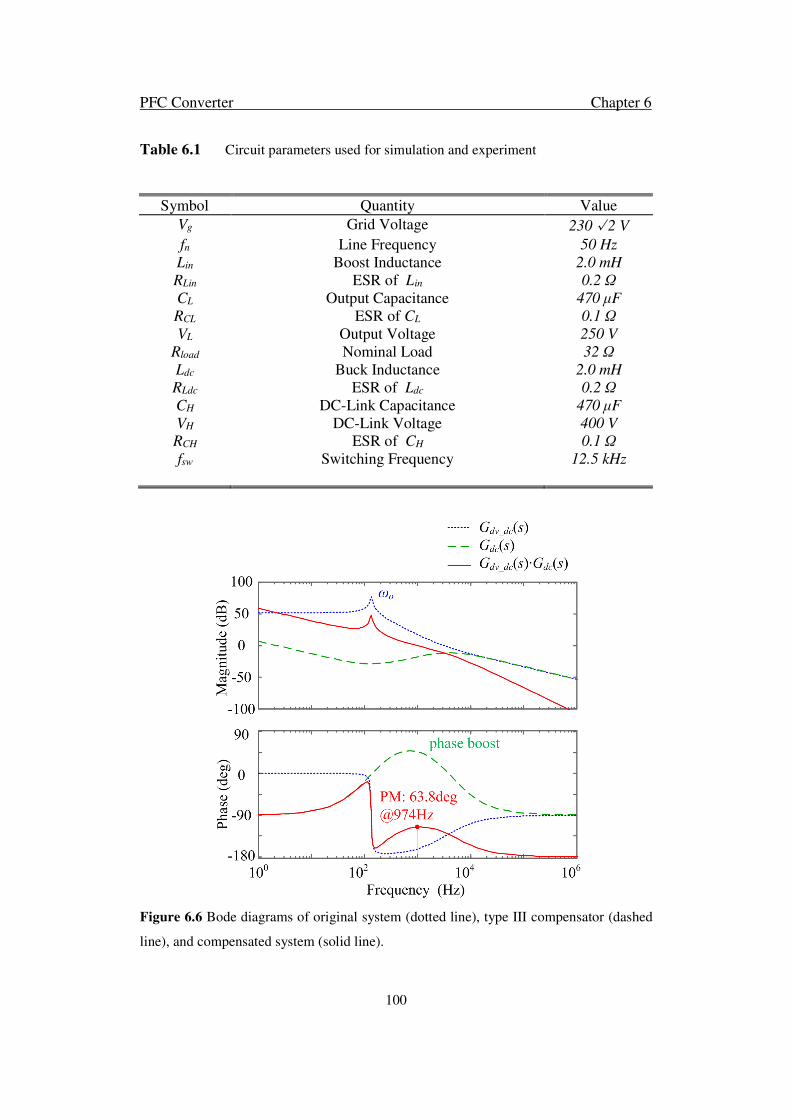
PFC Converter Chapter 6
100
Table 6.1 Circuit parameters used for simulation and experiment
Symbol Quantity Value
Vg Grid Voltage 230√2 V
fn Line Frequency 50 Hz
Lin Boost Inductance 2.0 mH
RLin ESR of Lin 0.2 Ω
CL Output Capacitance 470 μF
RCL ESR of CL 0.1 Ω
VL Output Voltage 250 V
Rload Nominal Load 32 Ω
Ldc Buck Inductance 2.0 mH
RLdc ESR of Ldc 0.2 Ω
CH DC-Link Capacitance 470 μF
VH DC-Link Voltage 400 V
RCH ESR of CH 0.1 Ω
fsw Switching Frequency 12.5 kHz
Figure 6.6 Bode diagrams of original system (dotted line), type III compensator (dashed
line), and compensated system (solid line).
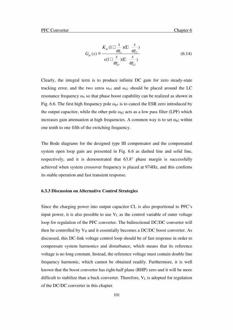
PFC Converter Chapter 6
101
1 2
1 2
(1 )(1 )
( )
(1 )(1 )
dc
z zdc
p p
s sK
G ss s
s
ω ω
ω ω
+ +
+ += (6.14)
Clearly, the integral term is to produce infinite DC gain for zero steady-state
tracking error, and the two zeros ωz1 and ωz2 should be placed around the LC
resonance frequency ωo so that phase boost capability can be realized as shown in
Fig. 6.6. The first high frequency pole ωp1 is to cancel the ESR zero introduced by
the output capacitor, while the other pole ωp2 acts as a low pass filter (LPF) which
increases gain attenuation at high frequencies. A common way is to set ωp2 within
one tenth to one fifth of the switching frequency.
The Bode diagrams for the designed type III compensator and the compensated
system open loop gain are presented in Fig. 6.6 as dashed line and solid line,
respectively, and it is demonstrated that 63.8° phase margin is successfully
achieved when system crossover frequency is placed at 974Hz, and this confirms
its stable operation and fast transient response.
6.3.3 Discussion on Alternative Control Strategies
Since the charging power into output capacitor CL is also proportional to PFC’s
input power, it is also possible to use VL as the control variable of outer voltage
loop for regulation of the PFC converter. The bidirectional DC/DC converter will
then be controlled by VH and it essentially becomes a DC/DC boost converter. As
discussed, this DC-link voltage control loop should be of fast response in order to
compensate system harmonics and disturbance, which means that its reference
voltage is no long constant. Instead, the reference voltage must contain double line
frequency harmonic, which cannot be obtained readily. Furthermore, it is well
known that the boost converter has right-half plane (RHP) zero and it will be more
difficult to stabilize than a buck converter. Therefore, VL is adopted for regulation
of the DC/DC converter in this chapter.

PFC Converter Chapter 6
102
In fact, other control strategies, like feed-forward of input voltage, implementing
an inner current control loop, and adding nonlinear control element, can also be
employed to further enhance the performance of buck converter. However, they
require even more sophisticated design efforts and are not compulsory for this
application. The type III compensator discussed above will suffice for regulation of
the proposed converter from both steady-state and transient points of view.
6.4 System Studies Results
Simulation study was carried out in MATLAB/Simulink environment and the
circuit parameters are listed in Table 6.1. The steady-state operation waveforms are
presented in Fig. 6.7. It can be seen that Q1 and Q2 operate alternatively and may
produce the desired three-level converter pole voltage VAB. The high level bus
voltage is not constant because the dc-link capacitor needs to absorb the system
double line frequency harmonic. This fluctuation voltage has basically no impact
to the regulation of the boost inductor current, because it can be easily compensated
by the fast current control loop. Thanks to the feed-forward mechanism of the open-
loop duty cycle, the grid current is almost sinusoidal and in phase with the grid
voltage, and its ripple component is very small because of the three-level output
voltage. As mentioned previously, the buck converter theoretically does not need
to switch when D2 is blocking. However, in order to deal with the system harmonic
power and ensure constant load voltage, the buck converter still has to work during
this operation mode.
A 2-kW prototype circuit was built in the laboratory for experimental validation of
the proposed PFC converter and the circuit parameters are basically the same as
those used in simulation, despite some very slight differences due to the tolerance
of passive components. The key active and passive components used for the tested
prototype are summarized in Table 6.2.

PFC Converter Chapter 6
103
Table 6.2 Key component used for experiment prototype
Component Description
Diode Rectifier Bridge GBPC2506, 25A/600V, MULTICOMP
Q1 … Q4 / D1 / D2 IKW30N60T, 30A/600V, INFINEON
Lin / Ldc 200 turns, 2*AWG#16, Core DT400-40, DMEGC
CL / CH EETED2W471LJ, 470 μF / 450V, PANASONIC
Figure 6.7 Simulated steady-state waveforms under 230-V/2-kW operation, C1: grid
voltage, C2: converter pole voltage, C3: buck converter current, and C4: grid current.
The proposed topology was first tested with standard 230-V/50-Hz high-line ac
input and its corresponding steady state experimental waveforms are presented in
Fig. 6.8. It is obvious that they can match well with those simulated ones presented
in Fig. 6.7. It should be noted that there is very slight current distortion during the

PFC Converter Chapter 6
104
mode transition period, and this is due to the limited compensation gain of the
controller.
Figure 6.8 Experimental steady-state waveforms under 230-V/2-kW operation, C1: grid
voltage, C2: converter pole voltage, C3: buck converter current, and C4: grid current.
Fig. 6.9 shows the dynamic response of the system when it subjects to 100% to 50%
step-down load change. As shown, the transient process is very smooth and there
is no obvious distortion in the grid current, and the high bus voltage can be well
regulated with insignificant voltage overshoot.
In contrast, Fig. 6.10 shows the experimental waveforms when the system
undergoes 50% to 100% step-up load change, and the probed signals are replaced
by the two dc bus voltages, rectified input voltage, and load current in order to
observe their dynamic responses. As can be seen, the load transient can be handled
by the high-voltage bus and the output voltage remains undisturbed. In order to

PFC Converter Chapter 6
105
examine the line frequency ripple component in the output voltage, its spectrum is
plotted in Fig. 6.11 and compared with that of the high dc bus. From Fig. 6.11, it is
clear that the high DC bus can absorb most of the second-order harmonics and
therefore, the load voltage can be kept as ripple free during both steady state and
dynamic process.
Figure 6.9 Experimental load step-down waveforms, C1: grid voltage, C2: converter pole
voltage, C3: buck converter current, and C4: grid current.
In addition to the high-line operation, the prototype was also tested with 120 V/50
Hz low-line input, and in this case, it is simplified to a conventional two-level PFC.
The steady-state waveforms under low-line operation with 1000-W load power is
presented in Fig. 6.12. It shows that the converter pole voltage becomes two-level,
and the input current is more sinusoidal than the high-line case. As discussed, the
buck converter now functions as a harmonic compensator and there is theoretically
no active power conversion required for it.
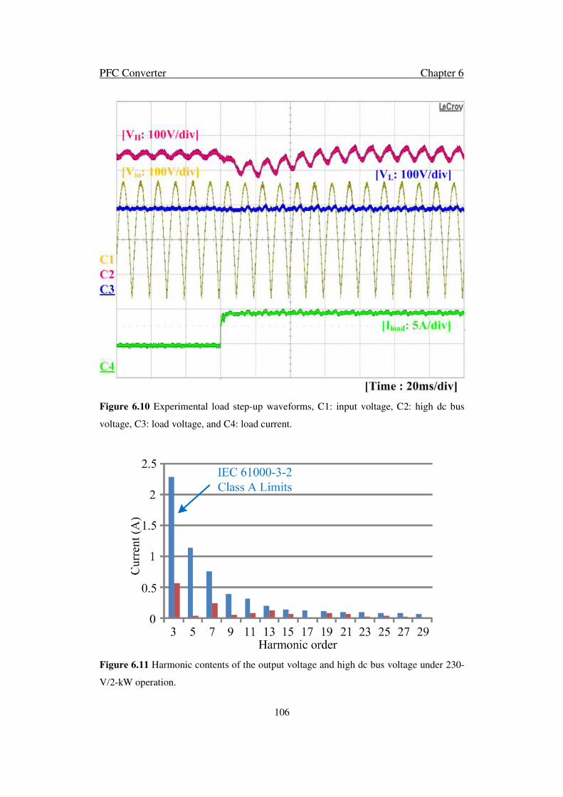
PFC Converter Chapter 6
106
Figure 6.10 Experimental load step-up waveforms, C1: input voltage, C2: high dc bus
voltage, C3: load voltage, and C4: load current.
Figure 6.11 Harmonic contents of the output voltage and high dc bus voltage under 230-
V/2-kW operation.

PFC Converter Chapter 6
107
Fig. 6.13 shows the spectrum of the steady-state grid currents under both high-line
and low-line operations. It can be seen that the results can well comply with the
IEC 61000-3-2 Class A standard, which is specified for equipment with power
rating above 600 W. The total harmonic distortion (THD) of the input current is
found to be 5.7% (calculated up to 50th harmonic order) under high-line operation
and it is improved to 3.1% under low-line case. As mentioned previously, this is
because the intermittent operation of the buck converter may impose disturbances
to the system and affect the input current regulation under high-line operation.
Figure 6.12 Experimental steady-state waveforms under 120-V/1-kW operation, C1: grid
voltage, C2: converter pole voltage, C3: buck converter current, and C4: grid current.
The proposed PFC converter is also compared with a conventional two-stage
solution, i.e., a boost PFC cascaded with a DC/DC buck converter, and its circuitry
is obtained by removing D1 and Q2 shown in Fig. 6.1. Therefore, the proposed
three-level PFC will have higher cost than the conventional one, and it is

PFC Converter Chapter 6
108
complicated with one fast recovery diode (D1), one switch (Q2), and one isolated
gate driver. The remaining active and passive components in the two-stage PFC are
exactly the same as those in the proposed one and therefore, a fair performance
comparison can be conducted.
Figure 6.13 Grid current spectrum at 230-V/2-kW operation and 120-V/1-kW operation,
shown in comparison with the IEC 61000-3-2 Class A harmonic current limits.
Figure 6.14 Efficiency curves of the proposed PFC converter under universal input
voltages, shown in comparison with the conventional two-stage solution.

PFC Converter Chapter 6
109
The efficiency tests were performed by a Fluke Norma 5000 power analyzer.
Different tests under universal input voltage conditions (85 to 265 Vrms) were
conducted for the two topologies. The output voltage and load power were fixed at
250 V and 2 kW, respectively, and the recorded efficiency curves are presented in
Fig. 6.14. As shown, the proposed PFC features higher efficiency than the
conventional one under all input conditions. During standard 230-V high-line
operation, 1% efficiency improvement can be obtained over the entire load range
and this confirms the superior performance of the proposed topology.
Figure 6.15 Efficiency curve of the proposed PFC converter under different output
voltages, shown in comparison with the conventional two-stage solution.
In addition to the efficiency versus input voltage curves, the efficiency versus
output voltage curve is also plotted in Fig. 6.15, and in this test, the converters were
operated with 230-V input voltage and nominal load power. Fig. 6.15 shows that
the proposed PFC can maintain much higher efficiency when the output voltage is
low. However, as the output voltage increases, the efficiency improvement will be
less significant because the proposed PFC essentially becomes equivalent to the
conventional two-stage PFC and the characteristic of three-level switching is lost.

PFC Converter Chapter 6
110
It should be noted that the power losses induced by the gate drivers were not
included in the efficiency measurement. Since the required gate charge is low and
the adopted switching frequency is also relatively slow, these power losses are
insignificant to the system overall efficiency and the performance comparison
presented previously is still reasonable.
6.5 Summary
In this chapter, a three-level quasi-two-stage single-phase PFC converter has been
presented. It has flexible output voltage and can be used for single-phase PHEV
charger applications, where the battery voltage can be either lower or higher than
the peak AC input voltage. The proposed converter features high quality input
current, three-level output voltage, and improved conversion efficiency. By
designing a fast regulation loop for the buck converter, the inherent fluctuating
power issue in single phase systems can also be resolved, and the load voltage will
be fairly constant and insensitive to load changes and external disturbances.
Moreover, a dynamic gain compensator is implemented in the current control loop
and in this case, its control bandwidth can be kept relatively constant irrespective
of the DC bus voltage change during two different operation modes. Therefore, the
grid current can be well regulated with low THD and high-power factor.
Experimental results obtained from a 2-kW laboratory prototype have been
presented in this chapter, which are in good agreement with the theoretical analysis.
The efficiency curves under universal input conditions were recorded from a
commercial power analyzer, and it is found that the proposed PFC may have 1%
efficiency gain under high-line operation as compared to a conventional cascaded
two-stage solution. This efficiency improvement is partly contributed by the
reduced switching voltage in the PFC stage, and also partly by the reduced power
conversion in the DC/DC buck stage.

Conclusions and Future Work Chapter 7
111
Chapter 7
Conclusions and Future Work
This thesis begins with reviewing of some basic conventional building
distributed networks and some popular control strategies. A novel
building hybrid microgrid is then proposed to overcome the drawbacks
existing in conventional building distributed networks. The topology
and controller of lifts system, building hybrid energy storage system
and EV charger are introduced in the following chapters. The future
work about improving building hybrid microgrid is also represented in
this chapter.

Conclusions and Future Work Chapter 7
112
7.1 Conclusion
This thesis starts with reviewing of some basic conventional building distributed
network concepts which form the fundamental of this thesis. Moreover, popular
control strategies about microgrid and its subsystems are reviewed. Conventional
building distributed network is based on AC microgrid. Unfortunately, such
networks have a number of multi reverse converters to integrate AC and DC devices,
which lead to large amount of multi reverse conversion loss. To overcome this
problem, a smart building hybrid microgrid is proposed in this thesis. The essential
components are necessary to achieve the smart building requirement in smart
building such as motor drives and energy storages. DTC and fuzzy logic controller
are introduced into motor drive controller. Hybrid energy storage is the promising
method to increase the system efficiency. These control strategies for building
subsystems are reviewed as the fundamental studies.
A novel building hybrid microgrid is introduced to reduce building power demand
and energy consumption, to increase building energy utilization efficiency and to
simplify building distribution network. Under various load and resource conditions,
the BHMG can maintain reliable operation. The BMDS, BPVS and HBES in
BHMG can change operating mode smoothly. AC/DC bus voltages are stable under
different operating conditions and during modes switching. The power can transfer
smoothly between AC and DC as well as between LDCB and CDCB. The duration
of the grid-tied operation and power input from utility grid have been reduced. The
building maximum demand and energy consumption have been significantly
reduced using the energy storage and direct power exchange through CDCB,
especially using the regenerated power from motor drives. Therefore, it can be
concluded that the CDCB and LDCB network configuration is more efficient
topology for power exchange among motors in driving and regenerating modes and
therefore can significantly reduce multiple reverse conversions in CBDN. A hybrid
building energy storage system (HBES) can provide cost-efficient solutions for
different operation problems.
Conclusions and Future Work Chapter 7
113
Then a novel lift control approach is studied. The novel control method includes
integrated operation optimization and motor DTC control. Fuzzy logic is
introduced into both optimize operation controller and motor DTC control. The
novel lift control is able to choose the optimal lift to operate. This lift will have the
shorter waiting time and riding time. It consumes less power; it can even regenerate
power and dump it back into SUPCAP. The motor controller with self-tuning has a
smaller ripple and shorter response and recovery time. Through this method, the
power efficiency in high rise multi-story building can be improved.
An adaptive area droop control approach has been investigated, which is able to
demonstrate an autonomous mode change and a stable operating performance for
energy storage converters in HESS. The novel control method is based on droop
control and integrates voltage regulation and power exchange control. The voltage
regulation is able to regulate a bus voltage to a constant value by adaptive tuning
the droop coefficient. This is well-suited for energy storage converter where a
constant bus voltage is required. The power exchange control is able to fast power
exchange between energy storage and building microgrid. Moreover, adaptive area
droop control is designed for battery and supercapacitor in HESS. The coordination
control is introduced for HESS which reduce the battery charging and discharging
times of miner cycle and discharge depth. Hence, the battery service time is
prolonged.
Electrical vehicles are promising devices to save energy. In smart building
microgrid, EV chargers are essential components for EV plug-in. A three-level
quasi-two-stage single-phase PFC converter has been presented. It has flexible
output voltage and can be used for single-phase PHEV charger applications, where
the battery voltage can be either lower or higher than the peak AC input voltage.
The proposed converter features high quality input current, three-level output
voltage, and improved conversion efficiency. By designing a fast regulation loop
for the buck converter, the inherent power fluctuating issue in single phase systems
can also be resolved, and the load voltage will be fairly constant and insensitive to

Conclusions and Future Work Chapter 7
114
load changes and external disturbances.
Moreover, a dynamic gain compensator is implemented in the current control loop
and in this case, its control bandwidth can be kept relatively constant irrespective
of the DC bus voltage change during two different operation modes. Therefore, the
grid current can be well regulated with low THD and high-power factor.
Experimental results obtained from a 2-kW laboratory prototype have been
presented in the paper, which are in line with the theoretical analysis. The efficiency
curves under universal input conditions were recorded from a commercial power
analyzer and it is found that the proposed PFC may have 1% efficiency gain under
high-line operation as compared to a conventional cascaded two-stage solution.
This efficiency improvement is partly contributed by the reduced switching voltage
in the PFC stage, and also partly by the reduced power conversion in the DC/DC
buck stage.
To conclude, this thesis covers a few challenging topics on building microgrid
configuration and its components controllers. All presented studies are verified by
simulations or experiments.
7.2 Future Work
This thesis has discussed some materials about building microgrid configuration
and related issues for subsystems in BHMG. Nevertheless, there are still some other
challenges yet to be explored. These unresolved challenges are briefly discussed
here to provide some insights for future investigation.
In chapter 5, a novel lift controller is proposed for integrating operating
optimization and motor DTC control. To make the system more efficient, the
controller can be further improved. MPC is widely used in motor drive control to
achieve specific objectives by setting the weight in objective function. Moreover,
the MPC is introduced in lift controller.

Conclusions and Future Work Chapter 7
115
The first step is to establish the lift motor model. The model has to include two
aspects, the motor mathematical dynamic equation and motor operating state
equation. The state space of motor model is generally expressed as
x Ax Bu•
= + (7.1)
where x is motor state variables vector, [ ]T
s sx i ϕ= ; u is stator voltage vector as
an input vector. Vector A and B are
( ) ( )
0
1
s r r s r r r r
s
r
R L R L j R jLA
R
LB
λ ω λ ω
λ
− + + − = −
=
where sR is stator resistance; rR is rotor resistance; sL is stator inductance; rL is
rotor inductance; mL is mutual inductance; rω is rotor speed; 21
s r mL L Lλ = − .
After discretization, in period sT , (7.1) can be written as:
( 1) 1 ( ) ( 1) ( 1)
( 1) ( ) ( 1) ( 1)
s s s ss s s
s s s
s s s s s s
T R T Ti k i k U k e k
L L L
k k U k i k R Tϕ ϕ
+ = − + + − +
+ = + + − +
uuuuuuuur uuuur uuuuuuuuur uuuuuuur
uuuuuuuur uuuuur uuuuuuuuur uuuuuuuur (7.2)
where k is the kth sampling time.
Based on (7.2), the torque predictive function can be written as:
( )( 1) ( 1) ( 1) ( 1) ( 1)e s s s s
T k P k i k k i kα β β αϕ ϕ+ = + + − + +uuuuuuuur
(7.3)
where P is the pole number; sαϕ and sβϕ are α and β elements of sϕ ; si α and si β
are α and β elements of si .
The objective function of motor drive is:

Conclusions and Future Work Chapter 7
116
( ) ( ) ( )( )
( ) ( )( )
( )
( )
22 **
1 2* *
2*
3 *
1
1 11 ( 1)
( 1) 1
1 1
1
s se e
e s
s s
s
k kT k T k
T k kg f P
U k U k
U k
g f P
ϕ ϕλ λ
ϕ
λ
+ − + + − + + + + = + − + + +
=
(7.4)
where 1λ , 2λ and 3λ are weight parameters which can determined the objective
priority. ( )f P is the objective function of lift operating optimization,
1 1 1 1
1 2 3 4
T
P O O O O = as in chapter 5. The output of ( )f P is 0 or 1. If the motor is
chosen, the output is 1. The control starts operating. 1g represents the multi
objective MPC motor controller.
In the motor model, the torque and flux are all related with stator voltage and the
stator voltage is determined by eight switching states, S1 to S8. According to this,
at the next sampling time, there has to be eight potential states. The controller
should choose the proper one to control the switch. Fig. 7. 1 shows the controller
operating process.
Figure 7.1 Motor MPC operating process.
x
tk tk+1 tk+2
Ts Ts
xref
S1
S2
S3
S4
S8
.
.
.
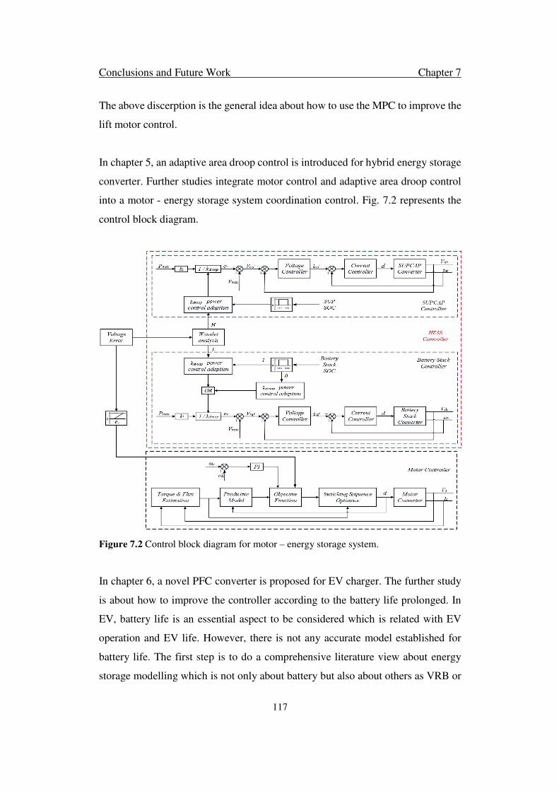
Conclusions and Future Work Chapter 7
117
The above discerption is the general idea about how to use the MPC to improve the
lift motor control.
In chapter 5, an adaptive area droop control is introduced for hybrid energy storage
converter. Further studies integrate motor control and adaptive area droop control
into a motor - energy storage system coordination control. Fig. 7.2 represents the
control block diagram.
Figure 7.2 Control block diagram for motor – energy storage system.
In chapter 6, a novel PFC converter is proposed for EV charger. The further study
is about how to improve the controller according to the battery life prolonged. In
EV, battery life is an essential aspect to be considered which is related with EV
operation and EV life. However, there is not any accurate model established for
battery life. The first step is to do a comprehensive literature view about energy
storage modelling which is not only about battery but also about others as VRB or

Conclusions and Future Work Chapter 7
118
supercapacitors. Related with EV design, the EV energy storage model is be
established and identified as the essential aspects about energy storage life.
According to this, the EV charger controller should be improved.

Publication
119
Publications
• D. Zhu, P. Wang, “Adaptive Area Droop Control for Hybrid Energy Storage
System in Building Microgrid”. IEEE Transactions on Industrial Electronics, under
review.
• D. Zhu, P. Wang, “A Smart Building Hybrid Microgrid for Energy Efficiency
Improvement”. IEEE Transactions on Smart Grid, under review.
• D. Zhu, P. Wang, X. Han, W. Qin, “Distributed Lift Operating Control in Building
Lift System”. IEEE International Conference on Information and Automation, ICIA
2015, Yunnan, China, Aug 8-10, 2015.
• Y. Tang, D. Zhu, P. Wang, F. Blaabjerg, “A Three-Level Quasi-Two-Stage Single-
Phase PFC Converter with Flexible Output Voltage and Improved Conversion
Efficiency”. IEEE Transactions on Power Electronics, Vol. 30 no. 2 pp. 717-726,
Feb 2015.
• P. Wang, C. Jin, D. Zhu, Y. Tang, P.C. Loh, F. H. Choo, “Distributed Control for
Autonomous Operation of a Three-Port AC/DC/DS Hybrid Microgrid”. IEEE
Transactions on Industrial Electronics, Vol. 62 no. 2 pp. 1279-1290, Feb 2015.
• D. Zhu, Y. Tang, C. Jin, P. Wang, F. Blaabjerg, “An Efficiency Improved Single-
Phase PFC Converter for Electric Vehicle Charger Applications”. 39th Annual
Conference of the IEEE Industrial Electronics Society, IECON 2013, Vienna,
Austria, Nov 10-14, 2013.
• C. Jin, Y. Tang, P. Wang, D. Zhu, F. Blaabjerg, “Reduction of DC-Link
Capacitance for Three-Phase Three-Wire Shunt Active Power Filters”. 39th Annual
Conference of the IEEE Industrial Electronics Society, IECON 2013, Vienna,
Austria, Nov 10-14, 2013.

Publication
120
References
121
References
[1] D&R International, Ltd, “2010 Building Energy Data Book,” Buildings
Technologies Program, Energy Efficiency and Renewable Energy, U.S.
Department of Energy, March, 2011.
[2] I. Cvetkovic, T. Thacker, D. Dong, G. Francis, V. Podosinov, D. Boroyevich,
F. Wang, R. Burgos, G. Skutt, and J. Lesko, “Future Home Uninterruptible
Renewable Energy System with Vehicle-to-Grid Technology,” in Energy
Conversion Congress and Exposition (ECCE), 2009., pp. 2675–2681.
[3] J. M. Guerrero, J. Matas, L. G. Vicuña, M. Castilla and J. Miret,
"Decentralized Control for Parallel Operation of Distributed Generation
Inverters Using Resistive Output Impedance" IEEE Trans. Industry
Electronics, vol. 54, no. 2, pp. 994-1004, Apl. 2007.
[4] D&R International, Ltd, “2011 Building Energy Data Book,” Buildings
Technologies Program, Energy Efficiency and Renewable Energy, U.S.
Department of Energy, March, 2012.
[5] R. H. Lasseter and P. Paigi, "Microgrid: A Conceptual Solution" in 35th
Annual IEEE Power Electronics Specializers Conference, Aachen, Germany.
2004, vol. 1, pp. 1, pp. 305-308.
[6] D. Karimipour and F. R. Salmasi, “Stability Analysis of AC Microgrids with
Constant Power Loads Based on Popov's Absolute Stability Criterion,”
IEEE Trans. Circuits and Systems II: Express Briefs, vol. 62, issue. 7, pp.
696-700, Feb. 2015.
[7] V. Nasirian, Q. Shafiee, J. M. Guerrero, F. L. Lewis and A. Davoudi,
“Droop-Free Distributed Control for AC Microgrids,” IEEE Trans. on
Power Electronics, vol. 31, no. 2, pp. 1600-1617, Mar. 2015.
[8] D. J. Hammerstrom, "AC versus DC Distribution Systems—Did We Get it
Right?" in IEEE Power Engineering Society General Meeting, June, 2007.
[9] J. Kim, J. M. Guerrero, P. Rodriguez, R. Teodorescu and K. Nam, "Mode
Adaptive Droop Control With Virtual Output Impedances for an Inverter-
Based Flexible AC Microgrid" IEEE Trans Power Electronics, vol. 26, no.

References
122
3, Mar 2011.
[10] M. Baran and N. Mahajan, "DC Distribution for Industrial System:
Opportunities and Challenges" IEEE Transactions on Industrial Application,
vol. 39. NO. 6, pp. 1596-1601, Nov. 2003.
[11] M. Chandorkar, D. Divan, and R. Adapa, “Control of parallel connected
inverters in standalone AC supply systems,” IEEE Trans. Ind. Appl., vol. 29,
no. 1, pp. 136–143, Jan./Feb. 1993.
[12] J. M. Guerrero, J. C. Vasquez, J. Matas, L. G. de Vicuna and M. Castilla,
"Hierarchical Control of Droop-Controller AC and DC Microgrids-A
General Approach Toward Standardization" IEEE Transaction on Industrial
Electronics, vol. 58, no. 1, pp. 158-172, Jan 2011.
[13] J. Lee, B. Han, and N. Choi, “DC Micro-grid Operational Analysis with
Detailed simulation Model for Distributed Generation,” in Energy
Conversion Congress and Exposition (ECCE), 2010 IEEE, 2010, pp. 3153–
3160.
[14] M. E. Baran and N. R. Mahajan, "DC Distribution for Industrial Systems:
Opportunities and Challenges" IEEE Trans. Indus Applications, vol. 39,
issue. 6, pp. 1596 – 1601, Nov. 2003.
[15] G. F. Reed, "DC technologies: Solutions to electric power System
Advancements" IEEE Power & Energy Magazine, pp. 10-17, Nov/Dec 2012.
[16] B. T. Patterson, "DC, Come Home" IEEE Power & Energy Magazine, pp.
10-17, Nov/Dec 2012.
[17] M. J. Sarker, B. Asare-Bediako, J. G Slootweg, W. L. Kling and B. Alipuria,
"DC Micro-Grid with Distributed Generation for Rural Electrification" in
47th International Universities Power Engineering Conference (UPEC),
Sept, 2012.
[18] H. Kakigano, Y. Miura, T. Ise and R. Uchida, "DC Micro-grid for Super
High Quality Distribution: System Configuration and Control of Distributed
Generations and Energy Storage Devices" in 37th IEEE Power Electronics
Specialists Conference, PESC '06, June, 2006.
[19] M. E. Baran and Nikhil R. Mahajan, "DC Distribution for Industrial Systems:

References
123
Opportunities and Challenges" IEEE Trans Indus Appl, vol. 39, no. 6,
Nov/Dec, 2003.
[20] J. M. Guerrero, M. Chandorkar, T. L. Lee and P. C. Loh, "Advanced Control
Architectures for Intelligent Microgrids-PartⅠ: Decentralized and
Hierarchical Control" IEEE Transactions on Industrial Electronics, vol. 60,
no. 4, April 2013.
[21] J. M. Guerrero, P. C. Loh, M. Chandorkar and T. L. Lee, "Advanced Control
Architectures for Intelligent Microgrids-PartⅡ: Power Quality, Energy
Storage, and AC/DC microgrids" IEEE Transactions on Industrial
Electronics, vol. 60, no. 4, April 2013
[22] X. Liu, P. Wang and P. Loh, “A Hybrid AC/DC Microgrid and Its
Coordination Control,” IEEE Trans. Smart Grid, vol 2, issue 2, pp. 278-286,
May. 2011
[23] A. A. A. Radwan and Y. A. I. Mohamed, “Assessment and Mitigation of
Interaction Dynamics in Hybrid AC/DC Distribution Generation Systems,”
IEEE Trans. Smart Grid, vol. 3, issue 3, pp. 1382-1393, Jun. 2012.
[24] P. Wang, L. Goel, X. Liu and F. H. Choo, "Harmonizing AC and DC: A
Hybrid AC/DC Future Grid Solution" IEEE Power & Energy Magazine, pp.
76-83, May/Jun 2013.
[25] R. Lasseter, A. Akhil, C. Marnay, J. Stephens, J. Dagle, R. Guttromson, A.
S. Melio-poulous, R. Yinger and L. Eta, “Integration of Distributed Energy
Resources: The CERTS Microgrid Concept,” white Paper prepared for U.
S. Department of Energy, California Energy Commission, Apr. 2002.
[26] Y. Zoka, H. Sasaki, N. Yomo, K. Kawahara and C. C. Liu, "An Interaction
Problem of Distributed Generators Installed in a Microgrid" in IEEE
International Conference on Electric Utility Deregulation, Restructuring
and Power Technologies (DRF'T 2004) , Hong Kong, April, 2004.
[27] Y. M. Chen, C. S. Cheng, and H. C. Wu, "Grid-Connected Hybrid PV/Wind
Power Generation System with Improved DC Bus Voltage Regulation
Strategy" in Twenty-First Annual IEEE Applied Power Electronics
Conference and Exposition, APEC '06. Jun, 2006.

References
124
[28] J. Sinopoli, “Defining a Smart Building: Part one,” in Smart Buildings LLC,
2013.
[29] J. Sinopoli, “Defining a Smart Building: Part two,” in Smart Buildings LLC,
2013.
[30] J. Sinopoli, “Defining a Smart Building: Part three,” in Smart Buildings LLC,
2013.
[31] J. Kim, J. M. Guerrero, P. Rodriguez, R. Teodorescu and K. Nam, "Mode
Adaptive Droop Control With Virtual Output Impedances for an Inverter-
Based Flexible AC Microgrid" IEEE Trans. Power Electronics, vol. 26, no.
3, pp. 689-701, Mar. 2011
[32] J. H. R. Enslin and P. J. M. Heskes, “Harmonic Interaction between a Large
Number of Distributed Power Inverters and the Distribution Network,”
IEEE Trans. Power Electronics, vol 19, no. 6, Nov. 2004.
[33] F. Shahnia, R. Majumder, A. Ghosh and G. Ledwich, FiruzZare, “Sensitivity
Analysis of Voltage Imbalance in Distribution Networks with Rooftop PVs,”
in Power and Energy Society General Meeting, 2010 IEEE, 2010 pp1-8.
[34] IEEE Guide for Design, Integration, and Operation of Distributed Resource
Island Systems with Electric Power Systems, IEEE Std. 1547.4.2011.
[35] P. C. Loh, D. Li, Y. Chai and F. Blaabjerg, "Autonomous Operation of
Hybrid Microgrid with AC and DC subgrids" IEEE Trans. Power
Electronics, vol. 28, no. 5, pp. 2214-2223, May. 2013.
[36] J. M. Guerrero, J. C. Vasquez, J. Matas, L. G. de Vicuna, and M.
Castilla,“Hierarchical control of droop-controlled AC and DC microgrids—
A general approach toward standardization,” IEEE Trans. Ind. Electron., vol.
58, no. 1, pp. 158–172, Jan. 2011.
[37] A. C. Barragan, C. A. Bautista and O. Florez, “Evaluation of the energetic
and operational efficiency in active power filters using fuzzy logic control
for microgrid applications,” in Power Electronics and Power Quality
Applications (PEPQA), IEEE Workshop, pp. 1-7, Jun. 2015.
[38] Y. Wang, S. Mao and R. M. Nelms, “On Hierarchical Power Scheduling for
the Macrogrid and Cooperative Microgrids,” IEEE Trans. Indus Inform, vol.

References
125
pp, issue. 99, pp. 1, Mar. 2015.
[39] N. Kinhekar, N. P. Padhy and H. O. Gupta, “Utility Oriented Demand Side
Management Using Smart AC and Micro DC Grid Cooperative,” IEEE
Trans. Power System, vol. pp, issue. 99, pp. 1-10, Mar. 2015.
[40] X. H. Guan, Z. B. Xu and Q. S. Jia, “Energy-Efficient Buildings Facilitated
by Microgrid,” IEEE Trans. Smart Grid, vol 1, issue 3, pp 243-252, Dec.
2010.
[41] J. Xiao, P. Wang and L. Setyawan, “Hierarchical control of hybrid energy
storage system in DC microgrids,” IEEE Trans. Ind. Electronics.,vol. 62, no.
8, pp. 4915-4924, Feb. 2015
[42] R. Kamel, A. Chaouachi, and K. Nagasaka, “Three control strategies to
improve the microgrid transient dynamic response during isolated mode: A
comparative study,” IEEE Trans. Ind. Electron., vol. 60, no. 4, pp. 1314–
1322, Apr. 2013
[43] L. K. Hoang, “Comparison of Field-Oriented Control and Direct Torque
Control for Induction Motor Drives” Industry Applications Conference,
Volume, 2, 1999.
[44] G. S. Buja and M. P. Kazmierkowski, “Direct Torque Control of PWM
Inverter-Fed AC Motors—A Survey” IEEE Trans Indus Electronics, vol. 51,
no. 4, Aug 2004
[45] J. P. He, C. X. Mao, J. M. Lu and J. W. Yang, “Design and Implementation
of an Energy Feedback Digital Device Used in Elevator” IEEE Trans.
Industry Electronics, vol 58, issue 10, pp 4636-4642, Aug. 2011.
[46] Luri, S. Etxeberria-Otadui, I. Rujas, A. Bilbao and E. Gonzalez, “Design of
a Super Capacitor based Storage System for Improved Elevator
Applications,” in Energy Conversion Congress and Exposition (ECCE),
2010 IEEE, 2010, pp.4534–4539.
[47] J. Fernandez, P. Cortes, J. Munuzuri and J. Guadix, “Dynamic Fuzzy Logic
Elevator Group Control System with Relative Waiting Time Consideration,”
IEEE Trans. Industry Electronics, vol 61, issue 9, pp 4912-4919, Mar. 2014
[48] X. D. Sun, K. H. Koh, B. G. Yu and M. Matsui, “Fuzzy-Logic-Based V/f

References
126
Control of an Induction Motor for a DC Grid Power-Leveling System Using
Flywheel Energy Storage Equipment” IEEE Trans Indus Electronics, vol.
56, no. 8, Aug 2009
[49] J. L. Da Silva, R. G. de Oliveira, S. R Silva, B. Rabelo and W. Hofmann, "A
Discussion about a Start-up Procedure of a Doubly-Fed Induction Generator
System" IEEE Nordic Workshop on Power and Industrial Electronics, June
9-11, 2008.
[50] Y. Liu, J. Zhao, R. Wang and C. Huang, "Performance Improvement of
Induction Motor Current Controllers in Field-Weakening Region for
Electric Vehicles" IEEE Transactions on Power Electronics, vol. 28, no. 5
May 2013.
[51] M. M. Rashid, N. A. Rashid, A. Farouq and M. A. Rahman, “Design and
Implementation of Fuzzy Based Controller for Modern Elevator Group”
IEEE Symposium on Industrial Electronics and Applications (ISIEA 2011),
September 25-28, 2011, Langkawi, Malaysia
[52] Y. Zhang, Y. Yi and J. Zhong, “The Application of the Fuzzy Neural
Network Control in Elevator Intelligent Scheduling Simulation” Third
International Symposium on Information Science and Engineering, Nov,
2009
[53] C. Chen, J. H. Wang, Y. S. Heo and Kishore, “Energy Management in a
Smart Residential Building,” IEEE Trans. Smart Grid, vol 4, issue 3, pp.
1401-1410, Aug. 2013.
[54] Z. B. Xu, X. H. Guan, Q. S. Jia, J. Wu, D. Wang and S. Y. Chen,
“Performance Analysis and Comparison on Energy Storage Devices for
Smart Building Energy Management,” IEEE Trans. Smart Grid, vol 3, issue
4, pp 2136-2147, Dec. 2012.
[55] P. Zhao, Suryanarayanan and S. Simoes, “An Energy Management System
for Building Structures Using a Multi-Agent Decision-Making Control
Methodology,” IEEE Trans. Smart Grid, vol 49, issue 1, pp 322-330, Jan.
2013.
[56] F. Inthamoussou, J. Pegueroles-Queralt, and F. Bianchi, “Control of a

References
127
supercapacitor energy storage system for microgrid applications,” IEEE
Trans. Energy Convers., vol. 28, no. 3, pp. 690–697, Sep. 2013.
[57] S. Lemofouet and A. Rufer, “A hybrid energy storage system based on
compressed air and supercapacitors with maximum efficiency point tracking
(MEPT),” IEEE Trans. Ind. Electronics., vol. 53, no. 4, pp. 1105–1115, Aug.
2006.
[58] A. Rufer and P. Barrade, “A supercapacitor-based energy storage system for
elevators with a soft commutated interface,” IEEE Trans. Ind. Appl., vol. 38,
no. 5, pp. 1151–1159, Sep./Oct. 2002.
[59] G. Tian; X. Ding and J. Liu, “Study of control strategy for hybrid energy
storage in wind- photovoltaic hybrid streetlight system,” in Open-Source
Software for Scientific Computation (OSSC), International Workshop, pp.
77-81, 2011.
[60] N. Mendis, K.M. Muttaqi and S. Perera, “Active power management of a
supercapacitor-battery hybrid energy storage system for standalone
operation of DFIG based wind turbines,” in IEEE Industry Applications
Society Annual Meeting, pp. 1-8, Oct. 2012
[61] A. Gee, F. Robinson and R. Dunn, “Analysis of battery lifetime extension
in a small-scale wind-energy system using supercapacitors,” IEEE Trans.
Energy Convers., vol. 28, no. 1, pp. 24–33, Mar. 2013.
[62] Electromagnetic Compatibility (EMC)—Part 3: Limits—Section 2: Limits
for Harmonic Current Emissions (Equipment Input Current < 16 A per
Phase), IEC Standard 61000-3-2, 1998.
[63] L. Huber, Y. Jang, and M. M. Jovanovic, “Performance evaluation of
bridgeless PFC boost rectifiers,” IEEE Trans. Power Electron., vol. 23, no.
3, pp. 1381–1390, May 2008.
[64] F. Musavi, W. Eberle, and W. G. Dunford, “A high-performance single-
phase bridgeless interleaved PFC converter for plug-in hybrid electric
vehicle battery chargers,” IEEE Trans. Ind. Appl., vol. 47, no. 4, pp. 1833–
1843, Jul./Aug. 2011.
[65] F. Musavi, M. Edington, W. Eberle, and W. G. Dunford, “Evaluation and

References
128
efficiency comparison of front end AC-DC plug-in hybrid charger
topologies,” IEEE Trans. Smart Grid, vol. 3, no. 1, pp. 413–421, Mar. 2012.
[66] M. Pahlevaninezhad, P. Das, J. Drobnik, P. K. Jain, and A. Bakhshai, “A
ZVS interleaved boost AC/DC converter used in plug-in electric vehicles,”
IEEE Trans. Power Electron., vol. 27, no. 8, pp. 3513–3529, Aug. 2012.
[67] C. Marxgut, F. Krismer, D. Bortis, and J.W. Kolar, “Ultra flat interleaved
triangular current mode (TCM) single-phase PFC rectifier,” IEEE Trans.
Power Electron., vol. 29, no. 2, pp. 873–882, Feb. 2014.
[68] D. Aggeler, F. Canales, H. Zelaya - De La Parra, A. Coccia, N. Butcher, and
O. Apeldoorn, “Ultra-fast dc-charge infrastructures for EV-mobility and
future smart grids,” in Proc. IEEE Power Energy Soc. Innovative Smart
Grid Technol. Conf. Europe, Oct. 2010, pp. 1–8.
[69] C. S. Moo, K. H. Lee, H. L. Cheng, and W. M. Chen, “A single-stage high-
power-factor electronic ballast with ZVS buck–boost conversion,” IEEE
Trans. Ind. Electron., vol. 56, no. 4, pp. 1136–1146, Apr. 2009.
[70] R. Watson, G. C. Hua, and F. C. Lee, “Characterization of an active clamp
flyback topology for power factor correction applications,” IEEE Trans.
Power Electron., vol. 11, no. 1, pp. 191–198, Jan. 1996.
[71] R. Zane and D. Maksimovic, “Nonlinear-Carrier control for high-power-
factor rectifiers based on up-down switching converters,” IEEE Trans.
Power Electron., vol. 13, no. 2, pp. 213–221, Mar. 1998.
[72] R. Redl, L. Balogh, and N. O. Sokal, “A new family of single-stage isolated
power-factor correctors with fast regulation of the output voltage,” in Proc.
IEEE Power Electron. Spec. Conf. (PESC), 1994, pp. 1137–1144.
[73] B. Singh, S. Singh, A. Chandra, and K. Al-Haddad, “Comprehensive study
of single-phase AC-DC power factor corrected converters with high-
frequency isolation,” IEEE Trans. Ind. Informat., vol. 7, no. 4, pp. 540–556,
Nov. 2011.
[74] J. Chen, D. Maksimovic, and R. W. Erickson, “Analysis and design of a
low-stress buck-boost converter in universal-input PFC applications,” IEEE
Trans. Power Electron., vol. 21, no. 2, pp. 320–329, Mar. 2006.
References
129
[75] A. J. Sabzali, E. H. Ismail, M. A. Al-Saffar, and A. A. Fardoun, “New
bridgeless DCM SEPIC and cuk PFC rectifiers with low conduction and
switching losses,” IEEE Trans. Ind. Appl., vol. 47, no. 2, pp. 873–881,
Mar./Apr. 2011.
[76] M. Mahdavi and H. Farzanehfard, “Bridgeless SEPIC PFC rectifier with
reduced components and conduction losses,” IEEE Trans. Ind. Electron.,
vol. 58, no. 9, pp. 4153–4160, Sep. 2011.
[77] E. H. Ismail, “Bridgeless SEPIC rectifier with unity power factor and
reduced conduction losses,” IEEE Trans. Ind. Electron., vol. 56, no. 4, pp.
1147–1157, 2009.
[78] A. A. Fardoun, E. H. Ismail, A. J. Sabzali and M. A. Al-Saffar, “New
efficient bridgeless Cuk rectifiers for PFC applications,” IEEE Trans. Power
Electronics, vol. 27, no. 7, pp. 3292–3301, 2012.
[79] T. Soeiro, T. Friedli, and J.W.Kolar, “Swiss Rectifier: A novel three-phase
buck-type PFC topology for electric vehicle battery charging,” in Proc. 26th
IEEE Appl. Power Electron. Conf. Exp., Feb. 5–9, 2012, pp. 2617–2624.
[80] T. Soeiro, T. Friedli, and J.W.Kolar, “Design and implementation of a three-
phase buck-type third harmonic current injection PFC rectifier SR,” IEEE
Trans. Power Electronics, vol. 28, no. 4, pp. 1608–1621, 2013.
[81] L. Huber, L. Gang, and M. M. Jovanovi´c, “Design-oriented analysis and
performance evaluation of buck PFC front end,” IEEE Trans. Power
Electron., vol. 25, no. 1, pp. 85–94, Jan. 2010.
[82] C.-Y. Chiang and C.-L. Chen, “Zero-voltage-switching control for a PWM
buck converter under DCM/CCM boundary,” IEEE Trans. Power Electron.,
vol. 24, no. 9, pp. 2120–2126, Sep. 2009.
[83] J.-H. Park and B.-H. Cho, “The zero voltage switching (ZVS) critical
conduction mode (CRM) buck converter with tapped-inductor,” IEEE Trans.
Power Electron., vol. 20, no. 4, pp. 762–774, Jul. 2005.
[84] X. Wu, J. Yang, J. Zhang, and M. Xu, “Design considerations of a high
efficiency soft-switched buck AC-DC converter with constant on-time
(COT) control,” IEEE Trans. Power Electron., vol. 26, no. 11, pp. 3144–

References
130
3152, Nov. 2011.
[85] X.Wu, J.Yang, J. Zhang, and Z.Qian, “Variable on-time (VOT) controlled
critical conduction, mode buck PFC converter for high input AC/DC HB-
LED lighting application,” IEEE Trans. Power Electron., vol. 27, no. 11, pp.
3144–3152, Nov. 2012.
[86] Y. Chen, Y. Nan, and Q. Kong, “A loss-adaptive self-oscillating buck
converter for LED driving,” IEEE Trans. Power Electron., vol. 7, no. 10,
pp. 4321–4328, Oct. 2012.
[87] Y. Jang and M. M. Jovanovic, “Bridgeless high-power-factor buck
converter,” IEEE Trans. Power Electron, vol. 26, no. 2, pp. 602–611, Feb.
2011.
[88] X. Xie, C. Zhao, L. Zheng, and S. Liu, “An improved buck PFC converter
with high power factor,” IEEE Trans. Power Electron, vol. 28, no. 5, pp.
2277–2284, Feb. 2013.
[89] Y. Ohnuma, and J. Itoh, “A novel single-phase buck PFC AC-DC converter
with power decoupling capability using an active buffer,” IEEE Trans. Ind.
Appl., in press. 17.
[90] B. L. Sawhney, C. R. Frink. Water, Air, and Soil Pollution. 1991, 57-58, 289-
296.
[91] Y. J. Lee, A. Khaligh, and A. Emadi, “Advanced integrated bidirectional
AC/DC and DC/DC converter for plug-in hybrid electric vehicles,” IEEE
Trans. Veh. Technol., vol. 58, no. 8, pp. 3970–3980, Oct. 2009.
[92] D&R International, Ltd, “2012 Building Energy Data Book,” Buildings
Technologies Program, Energy Efficiency and Renewable Energy, U.S.
Department of Energy, March, 2013.
[93] S. X. Chen, H. B. Gooi and M. Q. Wang, “Sizing of Energy Storage for
Microgrids,” IEEE Trans. Smart Grid, vol. 3, issue. 1, pp. 142-151, Aug.
2011.
[94] H. L. Huy, “Comparison of Field-Oriented Control and Direct Torque
Control for Induction Motor Drives,” IEEE Industry Applications
Conference, Thirty-Fourth IAS Annual Meeting. Conference, 1245 – 1252,
References
131
vol.2, 1999.
[95] K. Inoue, K. Ogata and T. Kato, "A Study on an Optimal Torque for Power
Regeneration of an Induction Motor" In Vehicle Power and Propulsion
Conference (VPPC), 2007 IEEE, pp. 1-6. 2007.
[96] P. C. Loh and F. Blaabjerg, "Autonomous Control of Distributed Storages in
Microgrids" in 8th International Conference on Power Electronics - ECCE
Asia, The Shilla Jeju, Korea, May 30-June 3, 2011
[97] N. Femia, Petrone, G. Spagnuolo and G. Vitelli, “Optimization of perturb
and observe maximum power point tracking method,” IEEE Trans. Power
Electronics, vol 20, issue 4, pp 963-973, Jun. 2005.
[98] M. E. Ropp and, S. Gonzalez, "Development of a MATLAB/SIMULINK
model of a Single-Phase Grid-Tied Photovoltaic System" IEEE Transaction
on Energy Converter, vol. 24, no. 1, pp. 195-202, Mar 2009.
[99] L. Gao, S. Liu and R. A. Dougal, “Dynamic Lithium-Ion Battery Model for
PV System Simulation,” IEEE Trans. Components and Package
Technologies, vol 25, issue 3, pp 495-505, Sep. 2002.
[100] K. W. Roth, D. Westphalen, J. Dieckmann, S. D. Hamilton and W. Goetzler,
“Energy Consumption Characteristics of Commercial Building HVAC
Systems Volume III: Energy Savings Potential,” for Building Technologies
Program, 2002.
[101] Y. H. Wang, J. L. Miao and Y. F. Wei, "The Research of Traction Motor
Energy-Saving Regenerative Braking Control Technology" International
Conference on Intelligent Computation Technology and Automation, 2010.
[102] S. Eren, M. Pahlevani, A. Bakhshai and P. Jain, “An adaptive droop dc-bus
voltage controller for a grid-connected voltage source inverter with LCL
filter,” IEEE Trans. Power Electronics., vol. 30, no. 2, pp. 547-560, Feb.
2015.
[103] O. Onar, J. Kobayashi, and A. Khaligh, “A bidirectional high-power-quality
grid interface with a novel bidirectional noninverted buck-boost converter
for PHEVs,” IEEE Trans. Veh. Technol., vol. 61, no.5, pp. 2018-2032, Jun.
2012.

References
132
[104] D. M. Van de Sype, K. de Gusseme, A. P. M. Van den Bossche, and J. A.
Melkebeek, “Duty-ratio feedforward for digitally controlled boost PFC
converters,” IEEE Trans. Ind. Electron., vol. 52, no. 1, pp. 108–115, Feb.
2005.
[105] C. Hao, X. Wang and A. Khaligh, "A Single Stage Integrated Bidirectional
AC/DC and DC/DC Converter for Plug-in Hybrid Electric Vehicles." In
Vehicle Power and Propulsion Conference (VPPC), 2011 IEEE, pp. 1-6.
2011.