Embed Size (px)
Citation preview

19-1
Cooling system components, removing and installing
Notes:
When the engine is warm the cooling system is under pressure. If necessary release pressure before commencing repair work.
Secure all hose connections with hose clamps of the same type as those installed at the factory.
Parts Catalog
VAG 1921 hose clip pliers are recommended when installing spring-type clips.
Replace all gaskets and seals.
The arrow markings on the coolant pipes and on the ends of the hoses must be aligned with each other.
Tightening torque for screw clamps: 2 Nm.
Draining and filling cooling system Page 19-4 .
Anti-freeze concentration Page 19-6 .
Coolant hose connection diagram Page 19-2 .
Checking cooling system for leaks with VAG 1274 and 1274/8 Page 19-29 .
Removing coolant pump Page 19-10 .
Removing coolant thermostat Page 19-14 .
Page 1 of 30Cooling system components, removing and installing
30/05/2004http://127.0.0.1:8080/audi/servlet/Display?action=Goto&target=_top&type=repair&id...

19-2
Cooling system components
1 -
Expansion tank
2 -
Filler cap for expansion tank
Testing
Page 19-30
3 - Intake manifold
4 -
Heating system heat exchanger
5 - Cylinder block
6 - Oil cooler
Removing and installing
Page 17-9 , Item 22
7 - Radiator
After replacing, refill complete system with fresh coolant
Page 2 of 30Cooling system components, removing and installing
30/05/2004http://127.0.0.1:8080/audi/servlet/Display?action=Goto&target=_top&type=repair&id...

19-3
8 - After-run coolant pump -V51-
Testing Page
19-9
9 - Coolant pump, coolant thermostat
Removing and installing coolant pump Page 19-10
Check for ease of movement
Removing and installing coolant thermostat
Page 19-14
Testing, operating data Page 19-17
10 - Turbocharger
Page 3 of 30Cooling system components, removing and installing
30/05/2004http://127.0.0.1:8080/audi/servlet/Display?action=Goto&target=_top&type=repair&id...

19-4
Cooling system, draining and filling
Draining
Notes:
Catch drained-off coolant in a clean confor re-use or disposal.
Coolant must only be mixed with clean dwater.
- Remove cap from coolant expansion tank
WARNING!
Hot steam can escape when the cap on texpansion tank is opened. Cover the capa cloth, and open it carefully.
- Remove center section of noise insulation
- Place drip tray VAG 1306 below engine.
Page 4 of 30Cooling system components, removing and installing
30/05/2004http://127.0.0.1:8080/audi/servlet/Display?action=Goto&target=_top&type=repair&id...

19-5
- Turn drain screw -arrow- on radiator anti-clockwise, install an extension hose to the connection if necessary.
- Also disconnect coolant hose at bottom of oil cooler -arrow-, and drain off remaining coolant.
Page 5 of 30Cooling system components, removing and installing
30/05/2004http://127.0.0.1:8080/audi/servlet/Display?action=Goto&target=_top&type=repair&id...

19-6
Filling
Notes:
Only use coolant additive G 012 A8 D - meeting specification TL VW 774 D. Identifiable by red color
CAUTION!
Do not use G 011 A8 C. The two different coolant additives G 011 A8 C and G 012 A8 D must not be mixed together. Otherwise this can result in serious damage to the engine.
If the fluid in the expansion tank is brown, this means G 012 A8 D has been mixed with another type of coolant. In this case, flush out the cooling system and put in fresh coolant. To flush the system, fill it with clean water and run the engine for about 2 minutes. This should remove very nearly all of the old coolant.
G 012 A8 D and coolant additives marked "meeting specification TL VW 774 D" prevent frost and corrosion damage, stop scaling and at the same time raise the boiling point of coolant. For these reasons the cooling system must be filled all year round with the correct anti-freeze and anti-corrosion additive.
Because of its high boiling point, the coolant improves engine reliability under heavy loads, particularly in countries with tropical climates.
Page 6 of 30Cooling system components, removing and installing
30/05/2004http://127.0.0.1:8080/audi/servlet/Display?action=Goto&target=_top&type=repair&id...

19-7
Frost protection is required down to about -25 C (in countries with arctic climates down to
about -35 C).
The coolant concentration must not be reduced by adding water even in warmer seasons and in warmer countries. The anti-freeze ratio must be at least 40 %.
If greater frost protection is required in very cold climates, the amount of G 012 A8 D can be increased, but only up to 60 % (this gives frost protection to about -40 C), as otherwise frost protection is reduced again and cooling effectiveness is also reduced.
If radiator, heat exchanger, cylinder head or cylinder head gasket is replaced, do not reuse old coolant.
Recommended mixture ratios:
Frost protection to
Anti-freeze concentration
Quantity of G
012A8 D 1)
Quantity of
water1)
-25 C
-35 C
40 %
50 %
2.0 ltr.
2.5 ltr.
3.0 ltr.
2.5 ltr.
1) Coolant quantity: 5.0 liters (may vary depending upon the vehicle equipment)
Page 7 of 30Cooling system components, removing and installing
30/05/2004http://127.0.0.1:8080/audi/servlet/Display?action=Goto&target=_top&type=repair&id...

19-8
- Screw in coolant drain plug.
WARNING!
Hot steam can escape when the cap on the expansion tank is opened. Cover the cap with a cloth, and open it carefully.
- Top up coolant to max. mark on expansion tank.
- Start engine and run at approx. 1500 RPM for max. 2 minutes and at the same time fill with coolant up to over-flow hole on expansion tank.
- Install expansion tank cap.
- Run engine until radiator fan cuts in.
- Stop engine.
- Check coolant level and top-up if necessary. When the engine is at normal operating temperature, the coolant level must be on the max. mark, when the engine is cold, between the min. and max. marks.
Page 8 of 30Cooling system components, removing and installing
30/05/2004http://127.0.0.1:8080/audi/servlet/Display?action=Goto&target=_top&type=repair&id...
19-9
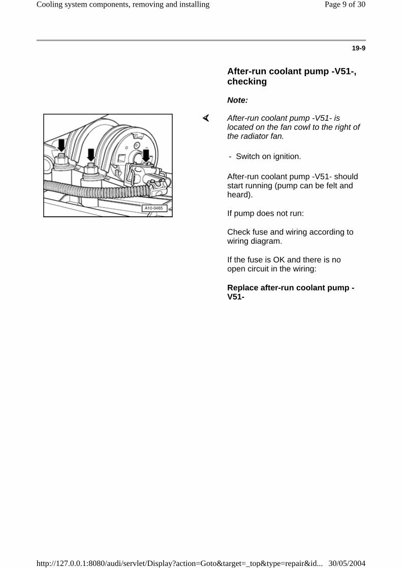
After-run coolant pump -V51-, checking
Note:
After-run coolant pump -V51- is located on the fan cowl to the right of the radiator fan.
After-run coolant pump -V51- should start running (pump can be felt and heard).
If pump does not run:
Check fuse and wiring according to wiring diagram.
If the fuse is OK and there is no open circuit in the wiring:
Replace after-run coolant pump -V51-
- Switch on ignition.
Page 9 of 30Cooling system components, removing and installing
30/05/2004http://127.0.0.1:8080/audi/servlet/Display?action=Goto&target=_top&type=repair&id...
19-10
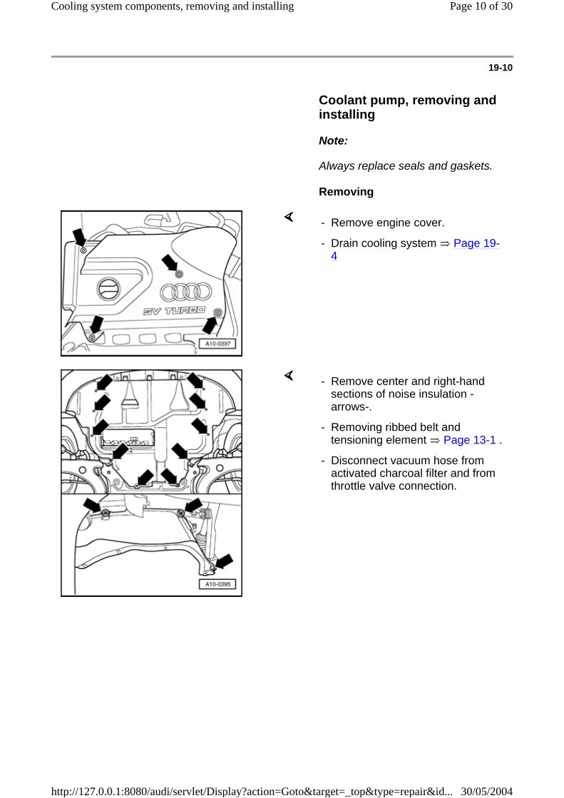
Coolant pump, removing and installing
Note:
Always replace seals and gaskets.
Removing
- Remove engine cover.
- Drain cooling system Page 19-4
- Remove center and right-hand sections of noise insulation -arrows-.
- Removing ribbed belt and tensioning element Page 13-1 .
- Disconnect vacuum hose from activated charcoal filter and from throttle valve connection.
Page 10 of 30Cooling system components, removing and installing
30/05/2004http://127.0.0.1:8080/audi/servlet/Display?action=Goto&target=_top&type=repair&id...

19-11
- Remove coolant expansion tank (see left-hand arrows) together with hoses.
- Unbolt power steering reservoir (see right-hand arrow). Do not disconnect the hoses.
- Remove toothed belt guards (upper and center) Page 13-13 .
- Set crankshaft to markings for TDC of No. 1 cylinder -arrows- by turning central bolt on crankshaft sprocket in direction of rotation.
Page 11 of 30Cooling system components, removing and installing
30/05/2004http://127.0.0.1:8080/audi/servlet/Display?action=Goto&target=_top&type=repair&id...

19-12
Note:
If it is not possible to insert the locking pin, carefully tension the pressure piston of the tensioning element just enough to allow the toothed belt to be removed.
Notes:
- Screw M5x55 stud -1- into toothed belt tensioning element. Screw hex nut -2- onto stud -1- using a large washer -3-.
- Tension pressure piston of tensioning element only until it can be secured with a locking pin (e.g. from lifting appliance 2024 A) -arrow-.
- Take toothed belt off camshaft sprocket.
The vibration damper and bottom toothed belt guard do not have to be removed.
The toothed belt should be left in position on the crankshaft sprocket.
Cover toothed belt with a cloth to protect it from coolant before removing coolant pump.
- Remove coolant pump securing bolts -1- and remove coolant pump -2-.
Page 12 of 30Cooling system components, removing and installing
30/05/2004http://127.0.0.1:8080/audi/servlet/Display?action=Goto&target=_top&type=repair&id...

19-13
Installing
Installation is carried out in the reverse order, when doing this note the following:
- Clean and smooth down sealing surface for O-ring as required.
- Moisten new O-ring with coolant G 012 A8 D.
- Install coolant pump. Installation position: plug in housing faces downward.
- Install toothed belt (adjust valve timing) Page 13-19
Note:
Follow all the instructions on removing and installing the toothed belt Page 13-10 .
- Installing ribbed belt and tensioning element Page 13-1 .
- Fill up with coolant Page 19-6 .
Tightening torque
Component Nm
Coolant pump to cylinder block 15
Page 13 of 30Cooling system components, removing and installing
30/05/2004http://127.0.0.1:8080/audi/servlet/Display?action=Goto&target=_top&type=repair&id...

19-14
Coolant thermostat, removing, instaand checking
Removing
Notes:
Always replace seals and gaskets.
Obtain radio anti-theft code on vehicles coded radio.
Secure all hose connections with hose cof the same type as those installed at thfactory.
Parts catalog
- With the ignition switched off, disconnect battery Ground strap.
- Drain cooling system Page 19-4
- Detach coolant hose at bracket for solenovalves above alternator.
- Unbolt bracket for solenoid valves -2- andfront of intake manifold and detach dipsticguide tube -4-.
Page 14 of 30Cooling system components, removing and installing
30/05/2004http://127.0.0.1:8080/audi/servlet/Display?action=Goto&target=_top&type=repair&id...

19-15
- Pull connector -3- and vacuum hose -1- out of bracket.
- Lay bracket clear to the side without detaching remaining connections.
- Disconnect coolant hose from elbow connection -3-.
- Remove bolts -4- and take off elbow connection, O-ring and thermostat -1-.
Page 15 of 30Cooling system components, removing and installing
30/05/2004http://127.0.0.1:8080/audi/servlet/Display?action=Goto&target=_top&type=repair&id...

19-16
Installing
- Clean and smooth down sealing surface for O-ring as required.
- Insert coolant thermostat. Installation position: bowed metal strip on thermostat must be vertical.
- Moisten new O ring with coolant G 012 A8 D.
- Tighten bolts.
- Fill up with coolant Page 19-6 .
Tightening torque
Component Nm
Elbow connection to cylinder block 15
Bracket for solenoid valves to intake manifold
10
- After connecting battery terminals, enter anti-theft code for radio
Radio operating instructions
WARNING!
If a battery charger is used to give the engine an assisted start, there is a risk that the control units in the vehicle will be damaged.
Page 16 of 30Cooling system components, removing and installing
30/05/2004http://127.0.0.1:8080/audi/servlet/Display?action=Goto&target=_top&type=repair&id...

19-17
- Close electric windows in front doors all the way to their top positions using electric switches.
- Then operate all electric window switches again for at least one second in the "close" direction to activate the automatic one-touch function.
- Set clock to correct time.
- Interrogate DTC memory:
Repair Manual , 1.8 Liter 4-Cyl. 5V Turbo Fuel Injection & Ignition, Engine Code(s): AMU, Repair Group 01; On Board Diagnostic , checking and erasing DTC memory
Note:
DTCs will have been stored in the memory because connectors have been disconnected. Therefore interrogate and erase DTC memory after installing engine.
Testing coolant thermostat
- Heat thermostat in water bath.
Starts to open
Fully open Opening travel
approx. 87 C approx. 102 C 1)
at least 7 mm
1) cannot be tested
Page 17 of 30Cooling system components, removing and installing
30/05/2004http://127.0.0.1:8080/audi/servlet/Display?action=Goto&target=_top&type=repair&id...

19-18
Coolant line, removing and installin
Removing
Note:
Always replace seals and gaskets.
- Obtain radio anti-theft code on vehicles wcoded radio.
- With the ignition switched off disconnect tbattery Ground strap.
- Drain cooling system Page 19-4
- Remove intake manifold Page 15-7 .
- Disconnect air duct -4- from air mass met
- Disconnect electrical connectors for air mmeter -1-.
- Remove bolts -2- and -3- and take off air housing.
Page 18 of 30Cooling system components, removing and installing
30/05/2004http://127.0.0.1:8080/audi/servlet/Display?action=Goto&target=_top&type=repair&id...

19-19
- Detach air intake hose from connection oturbocharger as follows:
- Disconnect vacuum hose -1- from air recirculation valve.
- Disconnect hose from pressure control for crankcase breather -2-.
- Disconnect electrical connector from chpressure control valve -3- (-N75-).
- Disconnect hose -4- from charge pressurcontrol valve -N75-.
- Disconnect hose -5- at bulkhead (hose lefrom solenoid valve to turbocharger).
- Take solenoid charge pressure control out of air intake hose and place it to onon the engine.
- Pull retainer off turbocharger connectiodetach air intake hose.
- Disconnect coolant hose from coolant lineleads to heat exchanger for heater).
Page 19 of 30Cooling system components, removing and installing
30/05/2004http://127.0.0.1:8080/audi/servlet/Display?action=Goto&target=_top&type=repair&id...

19-20
Vehicles with automatic transmission
All vehicles:
- Disconnect connectors:
1 - for solenoid valves (10-pin connector)
2 - for road speed sender -G68-
- Unbolt coolant pipe retainer from coolant line flange on left of cylinder head.
- Disconnect hose (leading to oil cooler) from coolant line.
- Remove crankcase breather line.
- Unbolt coolant line retainer from cylinder block.
- Disconnect hose (leading to coolant expansion tank) from coolant line (right).
- Unbolt coolant line retainer from tensioning element for ribbed belt.
- Pull tapered collar off oil dipstick tube.
Page 20 of 30Cooling system components, removing and installing
30/05/2004http://127.0.0.1:8080/audi/servlet/Display?action=Goto&target=_top&type=repair&id...

19-21
- Disconnect wires/connectors as follows:
-Knock sensor I -G61-
-Engine speed sensor -G28- (middle, grey)
-Knock sensor II -G66-
- Take connectors out of retainer.
- Remove oil line leading to turbocharger and unbolt retainer for oil line (both are attached to the oil filter bracket).
- Unbolt retainer for connectors.
- Unbolt knock sensors I and II.
- Unbolt left-hand coolant line flange from cylinder head.
- Detach coolant line.
Page 21 of 30Cooling system components, removing and installing
30/05/2004http://127.0.0.1:8080/audi/servlet/Display?action=Goto&target=_top&type=repair&id...

19-22
Installing
Installation is carried out in the reverse ordewhen doing this note the following:
- Before installing, clean and smooth downsealing surface for O-ring as required.
Radio operating instructions
- Moisten new O-ring -1- with G 012 A8 D aslide onto coolant pipe -2-.
- Push coolant pipe into opening in cylinde
- Fill up with coolant Page 19-6 .
- After connecting battery terminals, enter theft code for radio
- Close electric windows in front doors all tto their top positions using electric switch
- Then operate all electric window switchesfor at least one second in the "close" direactivate the automatic one-touch function
- Set clock to correct time.
Page 22 of 30Cooling system components, removing and installing
30/05/2004http://127.0.0.1:8080/audi/servlet/Display?action=Goto&target=_top&type=repair&id...

19-23
- Interrogate DTC memory:
Repair Manual , 1.8 Liter 4-Cyl. 5V Turbo Fuel Injection & Ignition, Engine Code(s): AMU, Repair Group 01; On Board Diagnostic , checking and erasing DTC memory
Note:
DTCs will have been stored in the memory because connectors have been disconnected. Therefore interrogate and erase DTC memory after installing engine.
Tightening torques
Component Nm
Coolant line bracket to cylinder block 10
Coolant line bracket to oil filter bracket
20
Coolant line bracket to coolant line flange
10
Page 23 of 30Cooling system components, removing and installing
30/05/2004http://127.0.0.1:8080/audi/servlet/Display?action=Goto&target=_top&type=repair&id...

19-24
Radiator, removing and installing
Note:
Always replace gaskets and seals.
Removing
- Obtain radio anti-theft code on vehicles wcoded radio.
- With ignition switched off disconnect battGround strap.
Repair Manual , Body Exterior, Repair GFront bumper, removing and installing
Note:
Only remove the cover section for the front
- Remove noise insulation -arrows-.
- Drain cooling system Page 19-4
- Release clamps and disconnect coolant hfrom connections on radiator (top and bot
- Remove front bumper:
Page 24 of 30Cooling system components, removing and installing
30/05/2004http://127.0.0.1:8080/audi/servlet/Display?action=Goto&target=_top&type=repair&id...

19-25
Vehicles without air conditioner:
- Disconnect connectors -1- on radiator fan cowl.
- Disconnect connector -2- from coolant Fan Control (FC) thermal switch -F18-.
- Unbolt radiator cowl -3- together with radiator fans (4 bolts) and pull downward to remove.
- Remove the 4 securing bolts -arrows- on the radiator.
- Lower radiator out of vehicle.
Page 25 of 30Cooling system components, removing and installing
30/05/2004http://127.0.0.1:8080/audi/servlet/Display?action=Goto&target=_top&type=repair&id...

19-26
Vehicles with air conditioner:
WARNING!
The air conditioner refrigerant circuit must not be opened.
Note:
To prevent damage to the condenser and refrigerant lines/hoses, ensure that the lines and hoses are not stretched, kinked or bent.
- Remove the four securing bolts -1- for the condenser.
- Remove the four securing bolts -2- for the radiator.
- Unbolt radiator fan control unit -J293- from left-hand longitudinal member (in front of battery).
- Carefully lower radiator between engine and condenser and remove from below.
Page 26 of 30Cooling system components, removing and installing
30/05/2004http://127.0.0.1:8080/audi/servlet/Display?action=Goto&target=_top&type=repair&id...

19-27
Installing
Installation is carried out in the reverse order, when doing this note the following:
Repair Manual , Body Exterior, Repair Group 63; Front bumper, removing and installing
Radio operating instructions
- Install mounts -3- and -4- on radiator as illustrated.
- Install radiator securing bolts (the help of a 2nd mechanic is required).
- Install front bumper:
- Replace O rings in the coolant hose connections.
- Fill up with coolant Page 19-6 .
- After connecting battery terminals, enter anti-theft code for radio
- Close electric windows in front doors all the way to their top positions using electric switches.
- Then operate all electric window switches again for at least one second in the "close" direction to activate the automatic one-touch function.
Page 27 of 30Cooling system components, removing and installing
30/05/2004http://127.0.0.1:8080/audi/servlet/Display?action=Goto&target=_top&type=repair&id...

19-28
- Set clock to correct time.
- Interrogate DTC memory:
Repair Manual , 1.8 Liter 4-Cyl. 5V Turbo Fuel Injection & Ignition, Engine Code(s): AMU, Repair Group 01; On Board Diagnostic , checking and erasing DTC memory
Note:
DTC will have been stored in the memory because connectors have been disconnected. Therefore interrogate and erase DTC memory after installing engine.
Tightening torques
Components Nm
Radiator fan cowl to radiator 10
Thermal switch to radiator 35
Radiator to lock carrier 10
Condenser to radiator 10
Control unit to longitudinal member 10
Page 28 of 30Cooling system components, removing and installing
30/05/2004http://127.0.0.1:8080/audi/servlet/Display?action=Goto&target=_top&type=repair&id...

19-29
Cooling system, checking for leaks
Test requirement:
Engine at operating temperature.
WARNING!
Hot steam can escape when the cap on the expansion tank is opened. Cover the cap with a cloth, and open it carefully.
- Remove cap from coolant expansion tank.
- Install tester VAG 1274 with adapter VAG 1274/8 onto expansion tank.
- Using hand pump on tester, build up a pressure of approx. 1.0 bar.
- If this pressure drops, locate the leak and repair.
Page 29 of 30Cooling system components, removing and installing
30/05/2004http://127.0.0.1:8080/audi/servlet/Display?action=Goto&target=_top&type=repair&id...

19-30
Testing pressure relief valve in filler cap
- Screw filler cap onto tester with adapter V1274/9.
- Attach hand pump and build up pressure
- The pressure relief valve should open at pressure of 1.4 - 1.6 bar.
Page 30 of 30Cooling system components, removing and installing
30/05/2004http://127.0.0.1:8080/audi/servlet/Display?action=Goto&target=_top&type=repair&id...