Embed Size (px)
Citation preview

15-1
Cylinder head, removing and installing
From 08.00 a new tightening roller and tightening device for the toothed belt is being installed. tightening roller must be adjusted in order to tension toothed belt.
Checking compression pressure Page 15-20
Notes:
When installing a replacement cylinder head with camshafts attached, grease contact surfaces between valve lifters and cam lubricating surfaces before attaching cylinder head cover.
Do not remove plastic covers protecting exposed valves until immediately before installing cylinder head.
When replacing cylinder head or cylinder head gasket, coolant must be replaced.
15-2
1 - Line
For crankcase ventilation
2 - Pressure line
For combination valve
3 - 10 Nm
4 - Cylinder head cover
5 - Cylinder head cover gasket
Replace if damaged
Before installing, coat sealing contact surfaces between bearing cap and cylinder head with D 454 300 A2 Page 15-31 , Fig. 4 and Page 15-31 Fig. 5
6 - Oil deflector
Note position: above intake camshaft
7 - 25 Nm
8 - Lifting eye
15-3
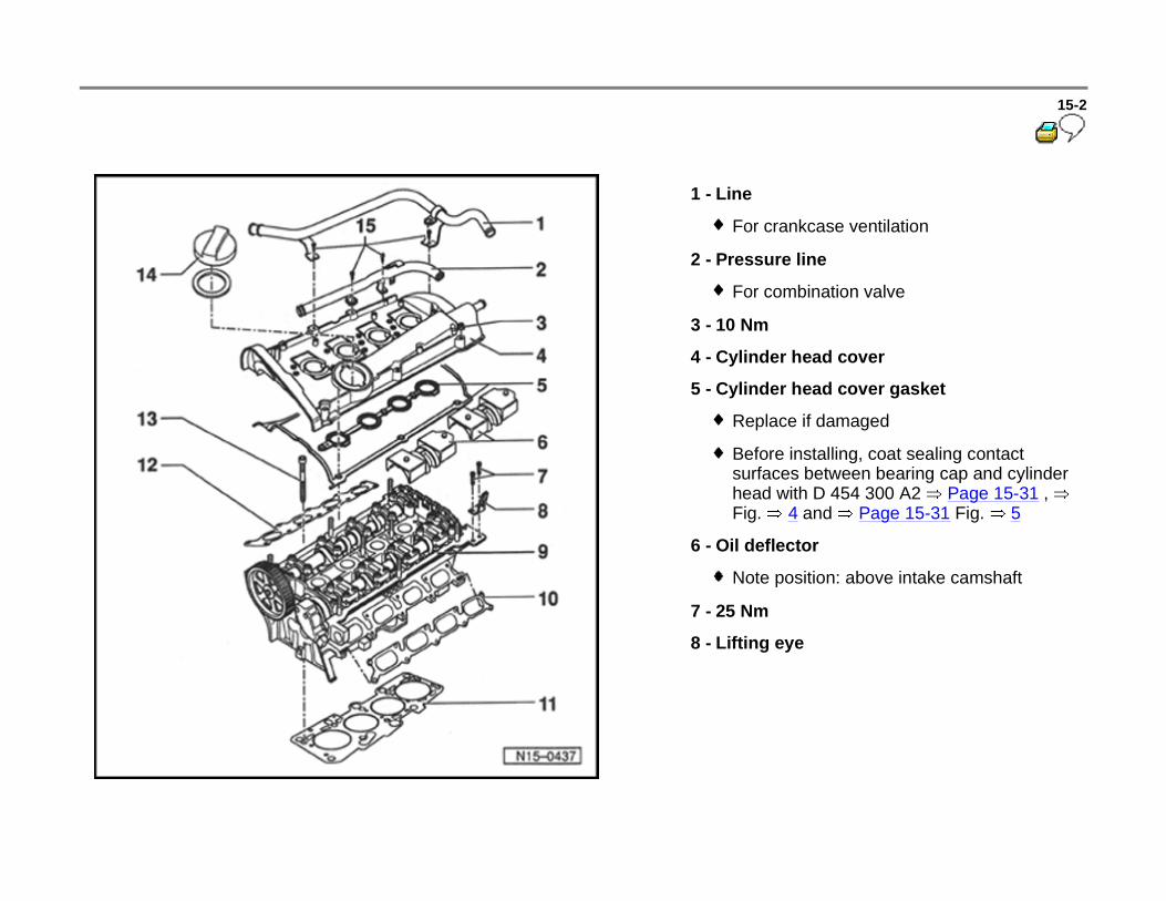
9 - Cylinder head
Check for warpage Fig. 1
Reface sealing surface Page 15-29 , Fig. 1
Removing and installing Page 15-14
After replacing, completely replace coolant
10 - Seal for intake line
Always replace
11 - Cylinder head gasket
Always replace
Metal gasket
After replacing, replace coolant
Note position: Identification: Part number must be visible from intake side.
15-4
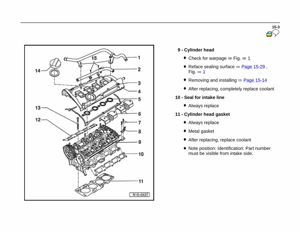
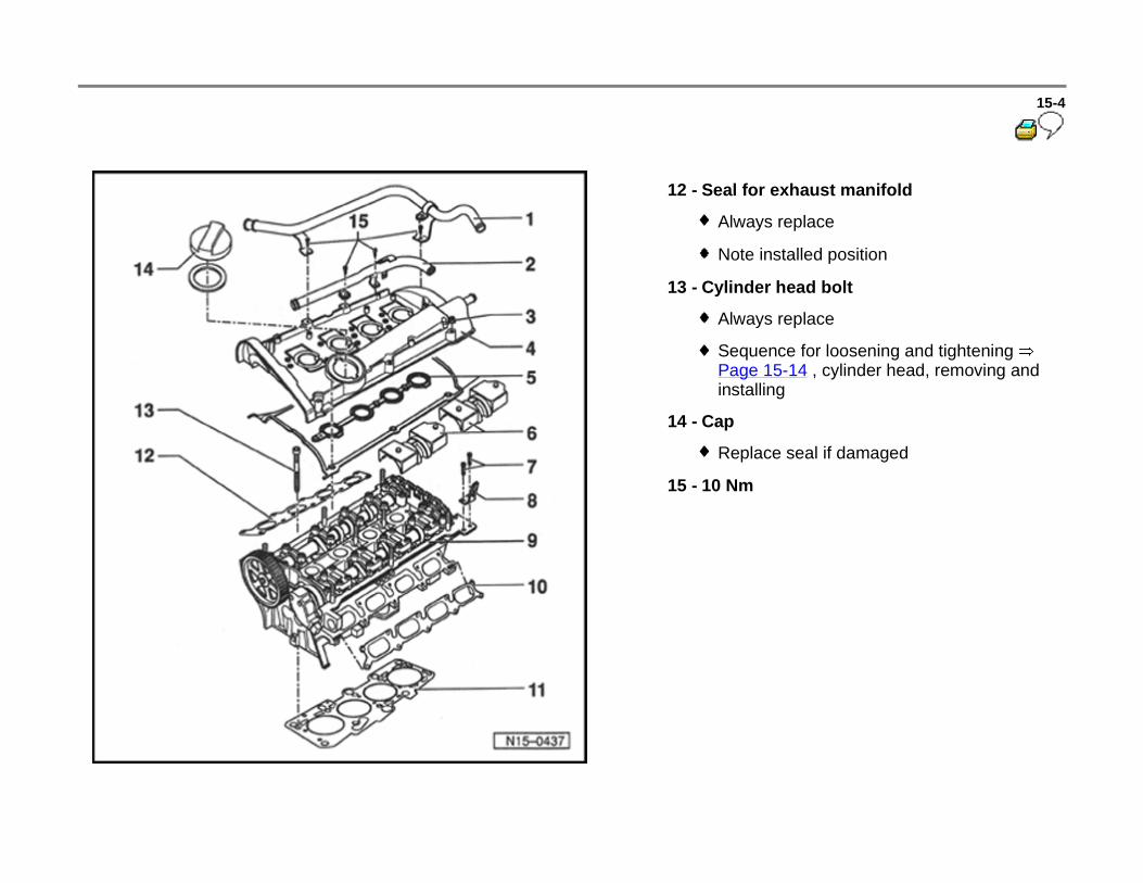
12 - Seal for exhaust manifold
Always replace
Note installed position
13 - Cylinder head bolt
Always replace
Sequence for loosening and tightening Page 15-14 , cylinder head, removing and installing
14 - Cap
Replace seal if damaged
15 - 10 Nm
15-5
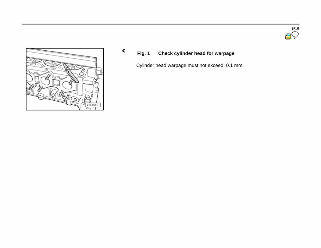
Cylinder head warpage must not exceed: 0.1 mm
Fig. 1 Check cylinder head for warpage

15-6
Toothed belt, removing, installing and tightening
Special tools and equipment
Tightening roller up to 07.00 (not adjustable)
Tightening roller from 08.00 (must be adjusted)
VAG 1331 Torque wrench (5 to 50 Nm)
VAG 1332 Torque wrench (40 to 200 Nm)
T10092 Tightening bolt
T40011 Pin
3387 Pin wrench
T10008 Locking plate

15-7
Removing
- Bring lock carrier into service position:
Repair Manual, Body Exterior, Repair Group 50; Body, front; Lock carrier service position
- Remove ribbed belt Page 13-14 .
- Remove tightening element for ribbed belt.
- Remove toothed belt guard upper.
- Mark direction of rotation of toothed belt.
- Adjust camshaft to TDC cylinder 1.

- Remove harmonic balancer/belt pulley.
- Remove lower and center toothed belt guard.

15-8
Tightening roller up to 07.00 (not adjustable)
Tightening roller from 08.00 (must be adjusted)
- Thread T10092 tightening bolt into tightening device for toothed belt.
- If necessary, align pressure piston before tightening, using needle nose pliers or thin wire (hole in pressure piston and hole in housing must overlap.
- Tighten pressure piston only far enough so that the pressure piston can be secured using T40001 pin.
Note:
Toothed belt tightening device is an oil damper device and can only be compressed slowly and with equal force. Excessive force during compression can damage tightening roller.
- Insert an hex wrench into hex socket up to stop and press tightening roller in counterclockwise direction (in direction of arrow) with uniform non-excessive force until the tightening device of the toothed belt can be aligned using T10008 locking plate.
15-9
Note:
Impact tab -A- of pin wrench must not be bent.
Continuation for all
Installing
Requirement
Work sequence
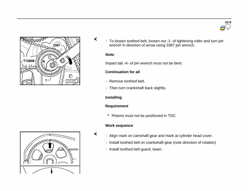
- To loosen toothed belt, loosen nut -1- of tightening roller and turn pin wrench in direction of arrow using 3387 pin wrench.
- Remove toothed belt.
- Then turn crankshaft back slightly.
Pistons must not be positioned in TDC.
- Align mark on camshaft gear and mark at cylinder head cover.
- Install toothed belt on crankshaft gear (note direction of rotation)
- Install toothed belt guard, lower.
15-10
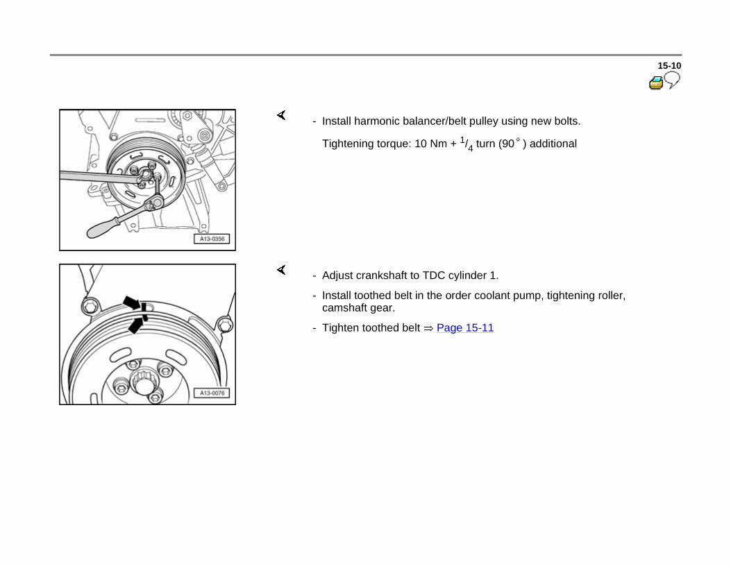
- Install harmonic balancer/belt pulley using new bolts.
Tightening torque: 10 Nm + 1/4 turn (90 ) additional
- Adjust crankshaft to TDC cylinder 1.
- Install toothed belt in the order coolant pump, tightening roller, camshaft gear.
- Tighten toothed belt Page 15-11
15-11
Tightening toothed belt
Requirements
Engine must not be more than hand-warm.
Engine is at TDC cylinder 1.
Work sequence
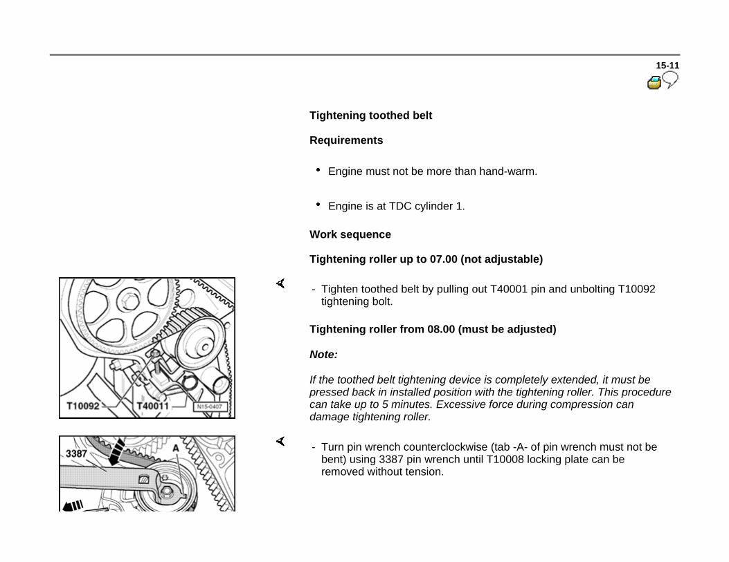
Tightening roller up to 07.00 (not adjustable)
Tightening roller from 08.00 (must be adjusted)
Note:
If the toothed belt tightening device is completely extended, it must be pressed back in installed position with the tightening roller. This procedure can take up to 5 minutes. Excessive force during compression can damage tightening roller.
- Tighten toothed belt by pulling out T40001 pin and unbolting T10092 tightening bolt.
- Turn pin wrench counterclockwise (tab -A- of pin wrench must not be bent) using 3387 pin wrench until T10008 locking plate can be removed without tension.

15-12
Continuation for all
- Turn pin wrench to the right in clockwise direction (direction of arrow) until a drill bit -2- with dimension -a- can be pulled through tightening lever and housing of tightening device.
Specified value dimension -a-: 8 mm.
- Hold tightening roller in this position and tighten securing nut of tightening roller as follows:
Specified value: 27 Nm
- Turn crankshaft two rotations and check whether the camshaft and crankshaft marks align with their reference points.

15-13
Tightening roller from 08.00 (must be adjusted)
If dimension -a- is not being reached
If dimension -a- is being reached
Continuation for all
- Check dimension -a- using a drill bit -2- between tightening lever and housing of tightening device.
Specified value: 6...10 mm
- Repeat procedure Page 15-11 , Tighten toothed belt.
- Toothed belt guard,install center and upper part.
- Install tightening device for ribbed belt.
Tightening torque: 25 Nm
- Install ribbed belt Page 13-14 .

15-14
Cylinder head, removing and installing
Special tools and equipment
3452 polydrive key
VAG 1306 drip tray
VAG 1331 torque wrench (5 to 50 Nm)
VAG 1332 torque wrench (40 to 200 Nm)
VAS 5024 assembly tool for spring-type clamps
15-15
Requirements
Engine must not be hotter than lukewarm.
Pistons must not be at Top Dead Center (TDC).
Procedure
- First determine whether an anti-theft coded radio is installed. If so, determine the correct radio anti-theft code and record.
- Switch ignition off and disconnect Battery Ground (GND) strap.
- Drain engine coolant Page 19-16 .
- Disconnect fuel supply line and return line at connection point at fuel rail. Fuel system is under pressure. Therefore place rags around the connection before disconnecting hoses.
- Seal off lines so that no dirt will get into fuel system.

15-16
- Unbolt catalytic converter from turbocharger.
- Disconnect all necessary connections:
Cooling system
Crankcase breather valve
Secondary air system
Exhaust turbocharger/regulation
Fuel injection and ignition system
- Remove upper portion of toothed belt guard.
- Loosen tensioner and lift toothed belt from camshaft gear.
- Remove cylinder head cover.
- Loosen and unbolt cylinder head bolts in specified sequence using 3452 polydrive key.
- Carefully remove cylinder head.
15-17
Installing
Notes:
Pocket holes in engine block for cylinder head bolts must be free of oil and coolant.
Do not remove new cylinder head gasket from package until immediately before installing.
Handle new gasket extremely carefully. Damage will cause leaking.
- Stuff clean cloths into cylinders so that no dirt or abrasive powder can get between cylinder wall and piston.
- Do not allow dirt or abrasive powder to get into coolant either.
- Carefully clean sealing surfaces of cylinder head and cylinder block. Avoid introducing scratches or scoring (do not use sandpaper with grit below 100).
- Thoroughly remove all sanding and grinding residue and remove cloths.

- Set piston of 1. Cylinder in TDC position and slightly turn crankshaft backward.
15-18
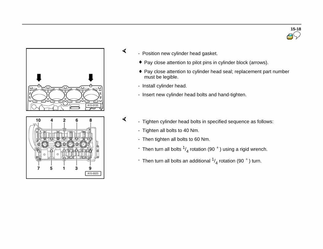
- Position new cylinder head gasket.
Pay close attention to pilot pins in cylinder block (arrows).
Pay close attention to cylinder head seal; replacement part number must be legible.
- Install cylinder head.
- Insert new cylinder head bolts and hand-tighten.
- Tighten cylinder head bolts in specified sequence as follows:
- Tighten all bolts to 40 Nm.
- Then tighten all bolts to 60 Nm.
- Then turn all bolts 1/4 rotation (90 ) using a rigid wrench.
- Then turn all bolts an additional 1/4 rotation (90 ) turn.

15-19
The rest of the installation follows the reverse of the removal procedures.
How to install toothed belt and adjust valve timing Page 15-6
How to fill up new coolant Page 19-16 .
- Perform work step "Procedure to follow after interruption of voltage supply".
Repair Manual, 1.8 Liter 4-Cyl. 5V Turbo Fuel Injection & Ignition, Engine Code(s): ATW, AUG, AWM, Repair Group 24; Engine Control Module, Procedure to follow after interruption of voltage supply
- Perform road test and check DTC memory:
Repair Manual, 1.8 Liter 4-Cyl. 5V Turbo Fuel Injection & Ignition, Engine Code(s): ATW, AUG, AWM, Repair Group 01, DTC memory; Engine Control Module (ECM) DTC memory, checking and erasing
15-20
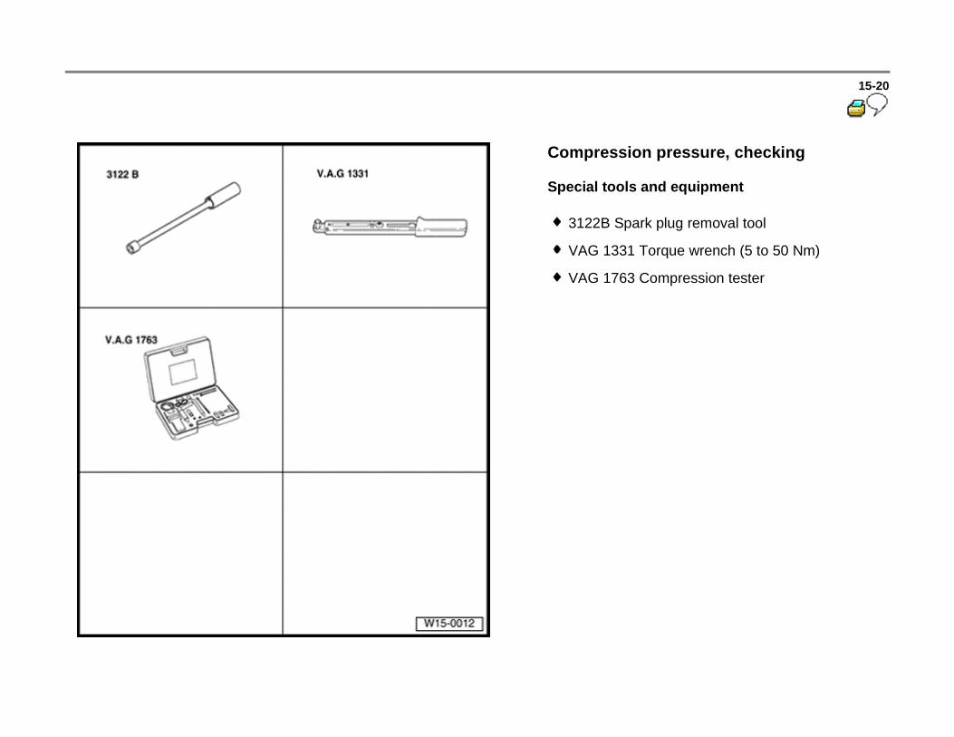
Compression pressure, checking
Special tools and equipment
3122B Spark plug removal tool
VAG 1331 Torque wrench (5 to 50 Nm)
VAG 1763 Compression tester
15-21
Test requirements
Engine oil temperature must be at least 30
C.
Voltage supply OK
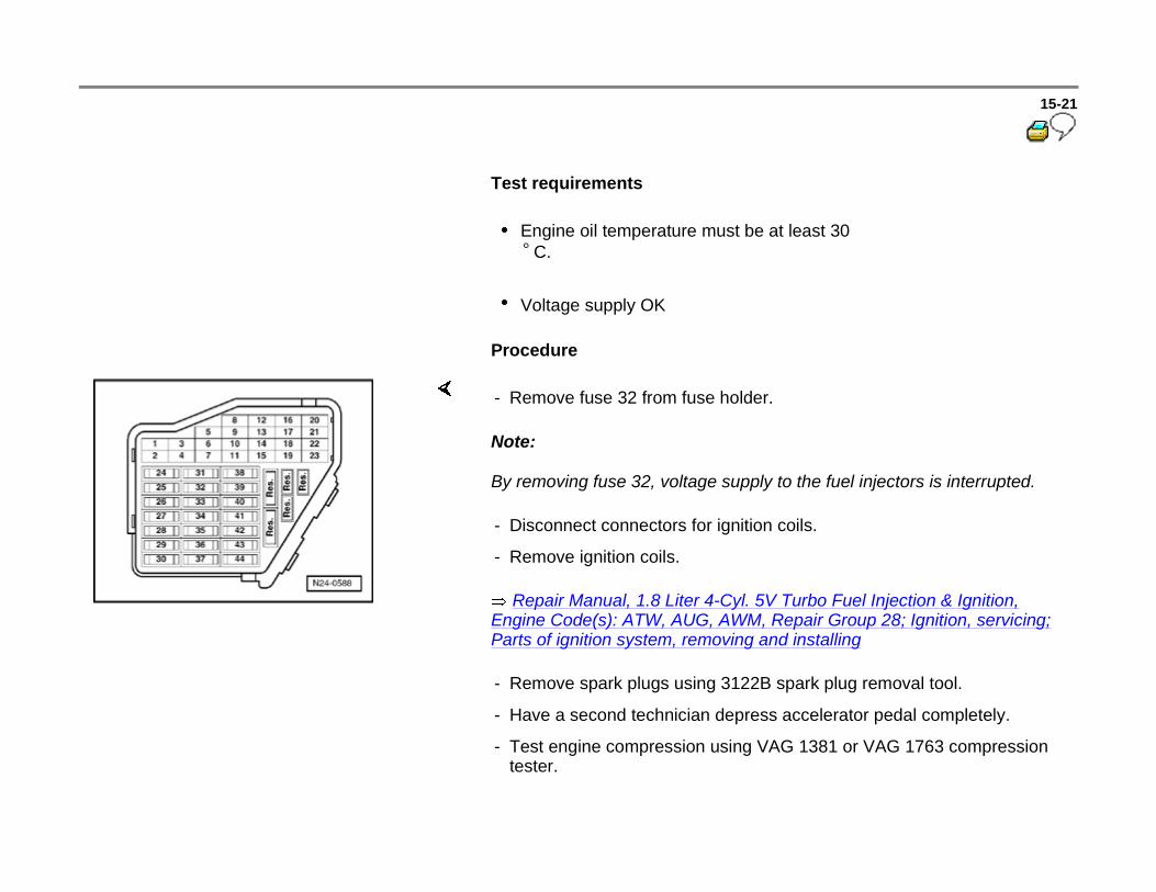
Procedure
Note:
By removing fuse 32, voltage supply to the fuel injectors is interrupted.
Repair Manual, 1.8 Liter 4-Cyl. 5V Turbo Fuel Injection & Ignition, Engine Code(s): ATW, AUG, AWM, Repair Group 28; Ignition, servicing; Parts of ignition system, removing and installing
- Remove fuse 32 from fuse holder.
- Disconnect connectors for ignition coils.
- Remove ignition coils.
- Remove spark plugs using 3122B spark plug removal tool.
- Have a second technician depress accelerator pedal completely.
- Test engine compression using VAG 1381 or VAG 1763 compression tester.
15-22
Note:
Using VAG 1381 or VAG 1763 compression tester operating instructions.
- Have a second technician operate the starter.
- Activate starter until no further pressure increases are indicated by VAG 1381 or VAG 1763 compression tester.
Compression values:
New: 10 to 14 bar positive pressure, Wear limit: 7.0 bar positive pressure
Tolerated deviation between cylinders: max. 3 bar
- Install spark plugs and ignition coils.
- Check DTC memory:
Repair Manual, 1.8 Liter 4-Cyl. 5V Turbo Fuel Injection & Ignition, Engine Code(s): ATW, AUG, AWM, Repair Group 01, DTC memory; DTC memory, checking and erasing