Embed Size (px)
Citation preview
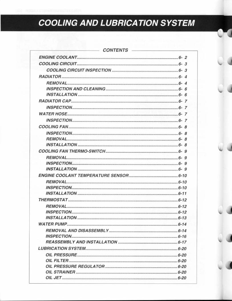
COOLING AND LUBRICATION SYSTEM
CONTENTSENGINE COOLANT 6- 2COOLING CIRCUIT 6- 3
COOLING CIRCUIT INSPECTION 6- 3RADIATOR 6- 4
REMOVAL 6- 4INSPECTION AND CLEANING 6- 6INSTALLATION 6- 6
RADIATOR CAP 6- 7INSPECTION 6- 7
WATER HOSE 6- 7INSPECTION 6- 7
COOLING FAN 6- 8INSPECTION 6- 8REMOVAL 6- 8INSTALLATION 6- 8
COOLING FAN THERMO-SWITCH 6- 9REMOVAL 6- 9INSPECTION 6- 9INSTALLATION 6- 9
ENGINE COOLANT TEMPERATURE SENSOR6-10REMOVAL 6-10INSPECTION 6-10INSTALLATION 6-11
THERMOSTAT 6-12REMOVAL 6-12INSPECTION 6-12INSTALLATION 6-13
WATER PUMP 6-14REMOVAL AND DISASSEMBLY 6-14INSPECTION 6-16REASSEMBLY AND INSTALLATION 6-17
LUBRICATION SYSTEM 6-20OIL PRESSURE 6-20OIL FILTER 6-20OIL PRESSURE REGULATOR 6-20OIL STRAINER 6-20OIL JET 6-20

WF
COOLING AND LUBRICATION SYSTEM 6- 1
OIL PUMP 6-20OIL PRESSURE SWITCH 6-20
OIL COOLER 6-21
REMOVAL 6-21INSPECTION AND CLEANING 6-21INSTALLATION 6-22
ENGINE LUBRICATION FLOW CHART 6-23
ENGINE LUBRICATION CIRCUIT 6-24
6-2 COOLING AND LUBRICATION SYSTEM
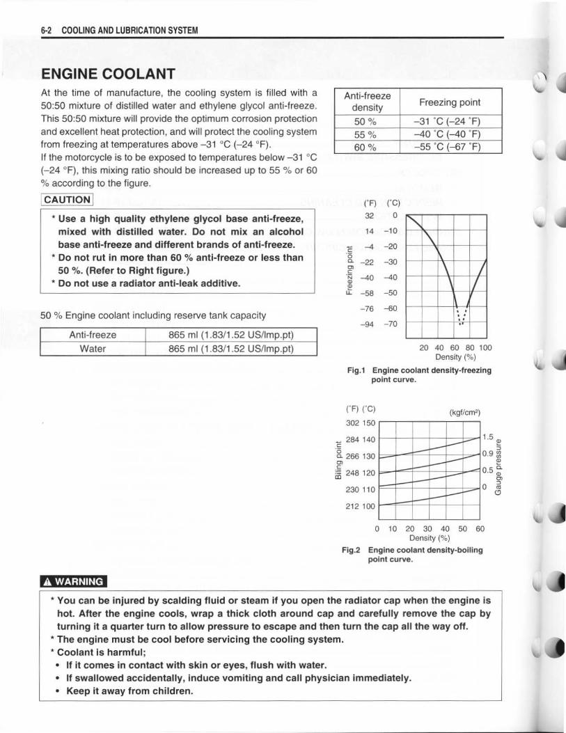
ENGINE COOLANTAt the time of manufacture, the cooling system is filled with a
50:50 mixture of distilled water and ethylene glycol anti-freeze .
This 50:50 mixture will provide the optimum corrosion protection
and excellent heat protection, and will protect the cooling system
from freezing at temperatures above -31 °C (-24 °F) .
If the motorcycle is to be exposed to temperatures below -31 °C
(-24 °F), this mixing ratio should be increased up to 55 % or 60
according to the figure .
A WARNING
20 40 60 80 100Density (%)
. .
•
You can be injured by scalding fluid or steam if you open the radiator cap when the engine is
hot. After the engine cools, wrap a thick cloth around cap and carefully remove the cap by
turning it a quarter turn to allow pressure to escape and then turn the cap all the way off .
* The engine must be cool before servicing the cooling system .
•
Coolant is harmful ;
•
If it comes in contact with skin or eyes, flush with water .
•
If swallowed accidentally, induce vomiting and call physician immediately .
•
Keep it away from children .
Anti-freezedensity
Freezing point
50% -31 °C (-24 °F)
55% -40 °C (-40 °F)
60% -55 °C (-67 °F)
Anti-freeze 865 ml (1 .83/1 .52 US/Imp .pt)
Water 865 ml (1 .83/1 .52 US/Imp .pt)
CAUTION ( C F) ( C C)32 0* Use a high quality ethylene glycol base anti-freeze,
mixed with distilled water . Do not mix an alcohol 14 -10
base anti-freeze and different brands of anti-freeze . -4 -20* Do not rut in more than 60 % anti-freeze or less than
C00. -22 -30
50 %. (Refer to Right figure .) 0)CN -40 -40
* Do not use a radiator anti-leak additive . U))
U- -58 -50
-76 -6050 % Engine coolant including reserve tank capacity
-94 -70
Fig .1 Engine coolant density-freezingpoint curve .
(°F) (°C)
302 150(kgf/cm 2)
284 140 1 .5 roc
a 266 130 0.9 No>
m 248 120P
0.5 C0)230 110 0 m
212 100
0 10 20 30 40 50 60Density (%)
Fig .2 Engine coolant density-boilingpoint curve .

dl~"
r
r
IF
COOLING CIRCUIT
THERMOSTAT
RESERVE TANK
RADIATOR
NO. 1 CYLINDER HEAD
NO. 1 CYLINDER
NO. 2 CYLINDER
NO. 2 CYLINDER HEAD
WATER PUMP
COOLING CIRCUIT INSPECTIONBefore removing the radiator and draining the engine coolant,
inspect the cooling circuit for tightness .
•
Remove the cowling. (SV650S) (C-7--7-6)
•
Loosen the radiator cap stop screw 10 . (SV650)
•
Remove the radiator cap O2 and connect the radiator tester
to the filler .
A WARNING
Do not remove the radiator cap when the engine is
hot.
•
Give a pressure of about 120 kPa (1 .2 kgf/cm2 , 17.0 psi) and
see if the system holds this pressure for 10 seconds .
•
If the pressure should fall during this 10-second interval, it
means that there is a leaking point in the system. In such a
case, inspect the entire system and replace the leaking com-
ponent or part .
A WARNING
When removing the radiator cap tester, put a rag on
the filler to prevent spouting of engine coolant .
CAUTION
Do not allow the pressure to exceed specified pres-
sure, or the radiator can be damaged .
COOLING AND LUBRICATION SYSTEM 6-3

6-4 COOLING AND LUBRICATION SYSTEM
RADIATOR
REMOVAL•
Remove the cowling. (SV650S) (r-7-7-6)
•
Drain engine coolant . (r--72-20)•
Disconnect the right and left radiator hoses from the radiator .
•
Disconnect the siphon hose from the radiator .
•
Disconnect the horn lead wires .

rI
.rr
•
Remove the radiator lower mounting bolt .•
Disconnect the cooling fan motor and its thermo-switch lead
wire coupler 10 .
•
Remove the radiator by upper mounting bolt .
•
Remove the cooling fan .
•
Disconnect the cooling fan thermo-switch .
•
Remove the cooling fan thermo-switch .
•
Remove the horn .
CAUTION
When removing the horn, hold the nut by spanner to
prevent the horn bracket distortion .
COOLING AND LUBRICATION SYSTEM 6- 5
6-6 COOLING AND LUBRICATION SYSTEM
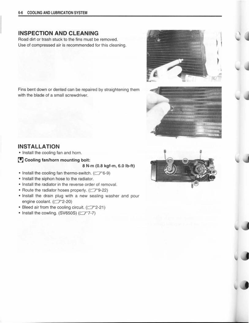
INSPECTION AND CLEANINGRoad dirt or trash stuck to the fins must be removed .
Use of compressed air is recommended for this cleaning .
Fins bent down or dented can be repaired by straightening themwith the blade of a small screwdriver .
INSTALLATION•
Install the cooling fan and horn .
0 Cooling fan/horn mounting bolt :
8 N.m (0.8 kgf-m, 6 .0 Ib-ft)
•
Install the cooling fan thermo-switch . ( l" 76-9)•
Install the siphon hose to the radiator .
•
Install the radiator in the reverse order of removal .
•
Route the radiator hoses properly. (=9-22)9-22)
•
Install the drain plug with a new sealing washer and pour
engine coolant. (=2-20)
•
Bleed air from the cooling circuit . (r--72-21)•
Install the cowling . (SV650S) (f" r7-7)
wr
1\
40,
164
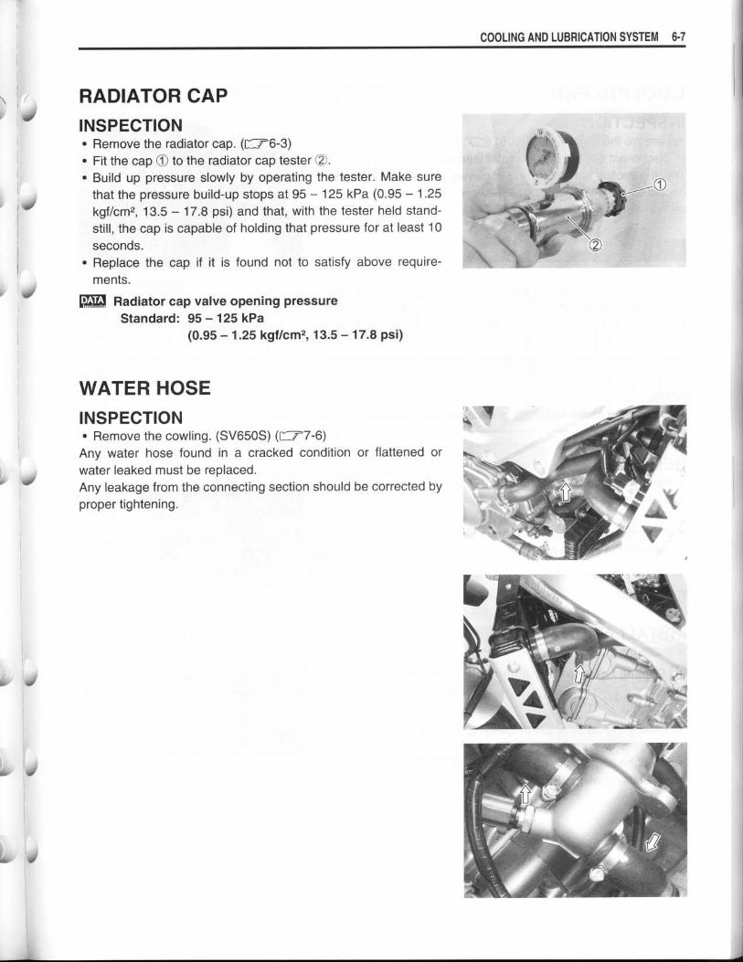
RADIATOR CAPINSPECTION•
Remove the radiator cap . (f" r6-3)•
Fit the cap 10 to the radiator cap tester (Z .•
Build up pressure slowly by operating the tester. Make sure
that the pressure build-up stops at 95 - 125 kPa (0.95 - 1 .25
kgf/cm2 , 13.5 - 17.8 psi) and that, with the tester held stand-
still, the cap is capable of holding that pressure for at least 10
seconds .
•
Replace the cap if it is found not to satisfy above require-
ments .
Radiator cap valve opening pressure
Standard: 95 - 125 kPa
(0.95 - 1 .25 kgf/cm2, 13.5 -17.8 psi)
WATER HOSEINSPECTION•
Remove the cowling . (SV650S) (C-77-6)
Any water hose found in a cracked condition or flattened or
water leaked must be replaced .
Any leakage from the connecting section should be corrected by
proper tightening .
COOLING AND LUBRICATION SYSTEM 6-7
i0

6-8 COOLING AND LUBRICATION SYSTEM
COOLING FAN
INSPECTION•
Remove the cowling . (SV650S) (C'-?;'7-6)
•
Disconnect the cooling fan motor lead wire coupler O .Test the cooling fan motor for load current with an ammeter con-
nected as shown in the illustration .
The voltmeter is for making sure that the battery applies 12 volts
to the motor . With the motor with electric motor fan running at
full speed, the ammeter should be indicating not more than 5
amperes .
If the fan motor does not turn, replace the motor assembly with a
new one .
NOTE:
When making above test, it is not necessary to remove the cool-
ing fan .
INSTALLATION•
Install the cooling fan to the radiator .
0 Cooling fan motor mounting bolt :
8 N .m (0 .8 kgf-m, 6 .0 Ib-ft)
•
Install the radiator.
•
Route the radiator hoses properly . (C--7-9-22)
•
Pour engine coolant . (C_.,-2-20)
•
Bleed the air from the cooling circuit . (C--r2-21)
•
Install the cowling . (SV650S) (C'77-6)
0
1
0
JI
REMOVAL•
Remove the cowling. (SV650S) (r--77-6)•
Drain engine coolant. (=2-20)
•
Remove the radiator. ( F-76-4)
•
Disconnect the cooling fan thermo-switch coupler 01 .•
Remove the cooling fan .

11
40
.r
s
of
COOLING FAN THERMO-SWITCHREMOVAL
•
Remove the cowling . (SV650S) (P-77-6)•
Drain engine coolant. (=2-20)
•
Disconnect the cooling fan thermo-switch lead wire coupler
90 .•
Remove the cooling fan thermo-switch O2.
INSPECTION
•
Check the thermo-switch closing or opening temperatures by
testing it at the bench as shown in the figure . Connect the
thermo-switch 1O to a circuit tester and place it in the OIL con-
tained in a pan, which is placed on a stove .
•
Heat the oil to raise its temperature slowly and read the col-
umn thermometer 20 when the switch closes or opens .
09900-25008: Multi circuit tester set
Tester knob indication : Continuity test ( •~ l))
Cooling fan thermo-switch operating temperature
Standard (OFF-*ON): Approx. 98 °C (208 °F)
(ON-*OFF): Approx. 92 °C (198 °F)
CAUTION
* Take special care when handling the thermo-switch .
It may cause damage if it gets a sharp impact .
* Do not contact the cooling fan thermo-switch 1O and
the column thermometer 02 with a pan .
INSTALLATION
•
Install a new O-ring 0 and apply engine coolant to the O-ring .
•
Tighten the cooling fan thermo-switch to the specified torque .
0 Cooling fan thermo-switch : 13 N.m (1 .3 kgf-m, 9 .5 Ib-ft)
•
Pour engine coolant . ([72-20)
•
Bleed air from the cooling circuit . ( F-7-2-21)
•
Install the cowling . (r-77-7)
COOLING AND LUBRICATION SYSTEM 6-9
(j) /

6-10 COOLING AND LUBRICATION SYSTEM
ENGINE COOLANT TEMPERATURESENSORREMOVAL•
Drain engine coolant . (l-7-2-20)•
Remove the throttle body . (=5-17)•
Disconnect the engine coolant temperature sensor lead wirecoupler .
•
Place a rag under the sensor and remove the engine coolanttemperature sensor D.
INSPECTION• Check the engine coolant temperature by testing it at thebench as shown in the figure . Connect the temperature sen-sor O to a circuit tester and place it in the WATER containedin a pan, which is placed on a stove .
•
Heat the water to raise its temperature slowly and read thecolumn thermometer O and the ohmmeter .
•
If the temperature sensor ohmic valve does not change in theproportion indicated, replace it with a new one .
Temperature sensor specification
If the resistance noted to show infinity or too much differentresistance value, replace the temperature sensor with a newone .
CAUTION
* Take special care when handling the temperaturesensor. It may cause damage if it gets a sharpimpact .
* Do not contact the engine coolant temperature sen-sor 90 and the column thermometer ~2 with a pan .
Temperature Standard resistance20 °C (68 °F) Approx. 2 .45 kI240 °C (104 °F) Approx. 1 .148 kQ60 °C (140 °F) Approx. 0 .587 kQ80 °C (176 °F) Approx. 0 .322 kQ

k
I
S
S
01 ale
Illiv
of
INSTALLATION•
Install a new sealing washer t0 .•
Tighten the engine coolant temperature sensor to the speci-fied torque .
0 Engine coolant temperature sensor :18 N .m (1 .8 kgf-m, 13.0 lb-ft)
CAUTION
Take special care when handling the temperature sen-sor. It may cause damage if it gets a sharp impact .
•
Pour engine coolant . (=2-20)2-20)•
Bleed air from the cooling circuit . (=2-21)•
Install the throttle body . (r-775-29)
COOLING AND LUBRICATION SYSTEM 6-1 1

6- 1 2 COOLING AND LUBRICATION SYSTEM
THERMOSTATREMOVAL•
Remove the throttle body . (r--75-117)•
Drain engine coolant. (Cr2-20)•
Place a rag under the thermostat case .
•
Remove the thermostat case cap .
•
Remove the thermostat ®.
INSPECTIONInspect the thermostat pellet for signs of cracking .
Test the thermostat at the bench for control action, in the follow-
ing manner .
•
Pass a string between flange, as shown in the photograph .
•
Immerse the thermostat in the WATER contained in a beaker,
as shown in the illustration . Note that the immersed thermo-
stat is in suspension . Heat the water by placing the beaker on
a stove 1O and observe the rising temperature on a thermom-
eter 02 .
• Read the thermometer just when opening the thermostat . This
reading, which is the temperature level at which the thermo-
stat valve begins to open, should be within the standard
value .
Thermostat valve opening temperature
Standard: Approx. 88 °C (190 °F)

r
6b, 0
•
Keep on heating the water to raise its temperature .
•
Just when the water temperature reaches specified value, the
thermostat valve should have lifted by at least 8 .0 mm
(0.31 in) .
Thermostat valve lift
Standard : Over 8.0 mm at 100 °C (Over 0 .31 in at 212 °F)
•
A thermostat failing to satisfy either of the two requirements,
start-to-open temperature and valve lift, must be replaced .
INSTALLATION•
Apply engine coolant to the rubber seal on the thermostat .
•
Install the thermostat .
NOTE:
The jiggle valve OA of the thermostat faces upside .
•
Install the thermostat case cap D.NOTE:
The rib of the thermostat case cap 10 should be faced upward.
•
Tighten the thermostat case bolts to the specified torque .
0 Thermostat case bolt : 10 N-m (1 .0 kgf-m, 7 .0 Ib-ft)
•
Pour engine coolant . (Ci2-20)
•
Bleed air from the cooling circuit . (C'2-21)
COOLING AND LUBRICATION SYSTEM 6-13
6-14 COOLING AND LUBRICATION SYSTEM
WATER PUMP
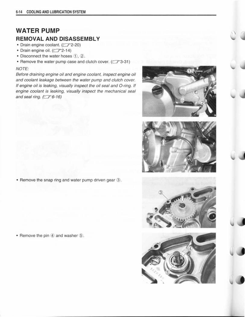
REMOVAL AND DISASSEMBLY•
Drain engine coolant . (=2-20)•
Drain engine oil. (=2-14)•
Disconnect the water hoses 90, 20 .•
Remove the water pump case and clutch cover . (f"7-3-31)
NOTE:Before draining engine oil and engine coolant, inspect engine oiland coolant leakage between the water pump and clutch cover .If engine oil is leaking, visually inspect the oil seal and 0-ring. Ifengine coolant is leaking, visually inspect the mechanical sealand seal ring . (F--76-16)
•
Remove the snap ring and water pump driven gear (1-
•
Remove the pin ® and washer ($) .
'!
J1
40

• Remove the water pump © from the clutch cover .
•
Remove the screws and separate the water pump .
•
Remove the 0-rings OO .
•
Remove the E-ring from the impeller shaft .
•
Remove the impeller from the other side .
•
Remove the mechanical seal ring ( and rubber seal © from
the impeller.
COOLING AND LUBRICATION SYSTEM 6- 1 5

6-16 COOLING AND LUBRICATION SYSTEM
•
Remove the bearing using the special tool .
. . 09921-20240 : Bearing remover set
NOTE:
If there is no abnormal noise, bearing removal is not necessary .
CAUTION
The removed bearing must be replaced with a new
one .
•
Remove the mechanical seal and oil seal using the special
tool .
. . 09913-70210: Bearing installer set (20 mm)
NOTE:
If there is no abnormal condition, the mechanical seal and the oil
seal removal is not necessary .
CAUTION
The removed mechanical seal and oil seal must be
replaced with a new one .
INSPECTIONBEARING
Inspect the play of the bearing by hand while it is in the water
pump case .
Rotate the inner race by hand to inspect for abnormal noise and
smooth rotation .
Replace the bearing if there is anything unusual .
MECHANICAL SEALVisually inspect the mechanical seal for damage, with particular
attention given to the sealing face .
Replace the mechanical seal that shows indications of leakage .
Also replace the seal ring if necessary .
1

OIL SEALVisually inspect the oil seal for damage, with particular attentiongiven to the lip .Replace the oil seal that shows indications of oil leakage .
BEARING CASEVisually inspect the bearing case for damage .Replace the water pump body if necessary .
REASSEMBLY AND INSTALLATION•
Install the oil seal using the special tool .
09913-70210 : Bearing installer set
NOTE:The stamped mark on the oil seal faces impeller side .
•
Apply a small quantity of the SUZUKI SUPER GREASE to theoil seal lip .
99000-25030: SUZUKI SUPER GREASE "A" (USA)99000-25010: SUZUKI SUPER GREASE "A" (Others)
COOLING AND LUBRICATION SYSTEM 6- 1 7
EM

6-18 COOLING AND LUBRICATION SYSTEM
•
Install the new mechanical seal using the special tool .
. .
. .
09913-70210 : Bearing installer set
•
Install the new bearings using the special tool .
09913-70210 : Bearing installer set
NOTE:The stamped mark on the bearing faces to the crankcase side .
•
Install the rubber seal 10 into the impeller .•
After wiping off the oily or greasy matter from the mechanicalseal ring, install it into the impeller .
NOTE:The paint marked side OA of the mechanical seal ring faces tothe impeller.
•
Apply SUZUKI SUPER GREASE to the impeller shaft .
99000-25030: SUZUKI SUPER GREASE "A" (USA)99000-25010 : SUZUKI SUPER GREASE "A" (Others)
•
Install the impeller to the water pump body .
•
Fix the impeller shaft with the E-ring OO .
•
Apply SUZUKI SUPER GREASE to the 0-rings .
99000-25030: SUZUKI SUPER GREASE "A" (USA)99000-25010: SUZUKI SUPER GREASE "A" (Others)
•
Install new 0-rings (T .
•
Fill the bearing with engine oil until engine oil comes out fromthe hole of the be bearing housing .
1
14
Li

I
•
Apply engine coolant to the 0-ring ® .•
Install a new 0-ring .
CAUTION
Use a new 0-ring to prevent engine coolant leakage .
•
Connect the water hoses .
•
Pour engine coolant . (C12-20)
•
Pour engine oil . (C'2-14)
COOLING AND LUBRICATION SYSTEM 6- 19

6-20 COOLING AND LUBRICATION SYSTEM
LUBRICATION SYSTEMOIL PRESSUREC'2-35
OIL FILTERf72-15
OIL PRESSURE REGULATORr--,7'3-60
OIL STRAINERf"T3-61
OIL JETr-7'3-62, -63 and -99
OIL PUMP=3-84 and -92
OIL PRESSURE SWITCH=3-61 and 8-36
4

r
OIL COOLER
REMOVAL•
Drain engine oil . (=2-14)•
Disconnect the oil cooler hoses .
•
Remove the oil cooler .
•
Remove the oil cooler fin guard net 10 .•
Remove the oil hoses I2 .
INSPECTION AND CLEANING
Inspect the oil cooler and hose joints for oil leakage . If any
defect are found, replace the oil cooler and oil hoses with thenew ones .
Road dirt or trash stuck to the fins must be removed .
Use of compressed air is recommended for this cleaning .
COOLING AND LUBRICATION SYSTEM 6- 2 1
6-22 COOLING AND LUBRICATION SYSTEM
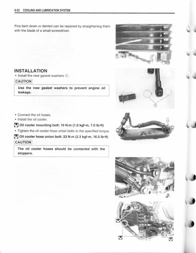
Fins bent down or dented can be repaired by straightening themwith the blade of a small screwdriver .
INSTALLATION•
Install the new gasket washers ® .
CAUTION
Use the new gasket washers to prevent engine oilleakage .
•
Connect the oil hoses .•
Install the oil cooler .
•
Oil cooler mounting bolt : 10 N-m (1 .0 kgf-m, 7.0 Ib-ft)
•
Tighten the oil cooler hose union bolts to the specified torque .•
Oil cooler hose union bolt : 23 N .m (2.3 kgf-m, 16.5 Ib-ft)
CAUTION
The oil cooler hoses should be contacted with thestoppers .

ENGINE LUBRICATION FLOW CHART
OIL PIPE
DRIVEN GEAR ANDBUSHING
DRIVEN GEAR ANDBUSHINGS
CLUTCH PUSH PEACE111
1111
111
1111
CLUTCH PLATES
PRIMARY DRIVENGEAR BUSHING
DRIVE SHAFT
COUNTER SHAFT
1
OIL PRESSUREREGULATOR
OIL GALLERY
1OIL JET (#14)
COOLING AND LUBRICATION SYSTEM 6-23
OIL FILTER
t~OIL JET
OIL PUMP
i
i
OIL PAN
OIL STRAINER
OIL PRESSURESWITCH
OIL COOLER
EXHAUSTCOMSHAFT JOURNAL
STARTER CLUTCH EXHAUSTCOMSHAFT JOURNALIr p
11I
.0STARTERDRIVEN GEAR BUSHINGo f, CAM FACES CAM FACES
. I EXHAUSTCAMSHAFT
CAM CHAIN CAM CHAIN
LEFT SIDECRANKSHAFTJOURNAL
RIGHTCRANKSHAFTJOURNAL
SIDECAM FACES CAM FACES
tINTAKECAMSHAFTJOURNALS
INTAKECAMSHAFTJOURNALS
CRANK PIN
tFRONT ANDBIG END BEARINGS
REAR CONROD INTAKECAMSHAFT
1 11
11 t
FRONT CYLINDER HEAD 1111 1111 REAR CYLINDER HEADFRONTCYLINDER
PISTON ANDWALL
REARCYLINDER
PISTON ANDWALL tIIr1
11Ilrrt1REAR CYLINDER REAR CYLINDER
I I
t PISTON COOLINGOIL JET (#13)
PISTONOIL
COOLINGJET (#13) t
OIL JET (#14) OIL JET (#14)
LEFT SIDE CRANKSHAFT JOURNAL BEARING RIGHT SIDE CRANKSHAFT JOURNAL BEARING

6-24 COOLING AND LUBRICATION SYSTEM
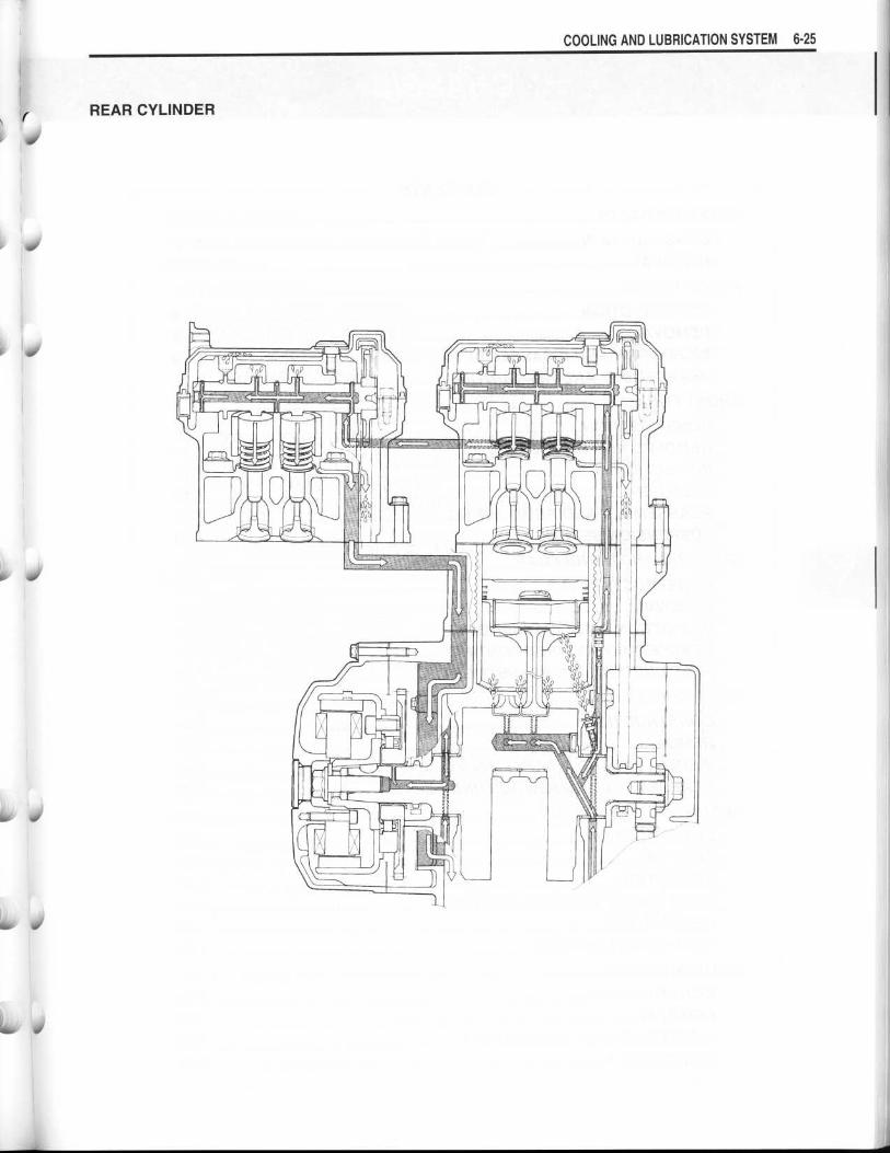
ENGINE LUBRICATION CIRCUIT
FRONT CYLINDER
I I
7
T~ 'r
W=_
. I OW
411111
/1 11i1i1iTiiill-
ihlihlilhr
I..
1J
1 .I
0
lw
i
40
60 w
REAR CYLINDER
COOLING AND LUBRICATION SYSTEM 6- 25