Embed Size (px)
Citation preview

8/13/2019 Convergence of Radio systems with Fiber
http://slidepdf.com/reader/full/convergence-of-radio-systems-with-fiber 1/4
Simultaneous Transmission of Gigabit Wireline
Signal and ECMA 387 mmW over Fiber Using a
Single MZM in Multi-Band ModulationTong Shao, Flora Paresys, Yannis Le Guennec, Ghislaine Maury, Nicolas Corrao, and Béatrice Cabon
Institut de Microélectronique, Electromagnétisme et Photonique - LAboratoire d’Hyperfréquences et de Caractérisation
Grenoble, France
Abstract —We propose a multi-band radio over fiber system
compatible with wired and 60GHz band wireless transmission by
implementing two-band modulation with a single Mach-Zehnder
modulator. In this paper, broadband millimeter wave at 60 GHz
band, which is compliant with the ECMA 387 standard, is
generated by photodetection after 25 km long optical fiber
transmission. Furthermore, baseband transmission, which feeds
up the requirement of fiber-to-the-Home, has been realized
simultaneously.
Keywords —radio over fiber (RoF), photodetection, wavelength
division multiplexing (WDM), multi-band modulation,
fiber-to-the-home (FTTH).
I. I NTRODUCTION
adio over Fiber (RoF) technology has raised great interestin the last decade to provide optical transmission of radio
signals to numerous simplified base stations (BSs). Anothermain advantage of RoF technology relies on the possibility to
centralize broadband optical signal processing functions suchas optical mmW generation, with the objective of limiting theuse of expensive broadband electronics in BSs [1]. Differentapproaches have been proposed to generate broadband mmWsignals in order to meet the requirements of different standards,such as ECMA 387 [2] or IEEE 802.15.3c [3].
Considering optical access networks wavelength divisionmultiplexing (WDM) passive optical networks (PON)technology has recently attracted much attention forfiber-to-the-home (FTTH) access networks. WDM-PON cansupport higher data rate to the end user than typical PONtechnologies.
In order to reduce the infrastructure cost for high data rate
wired and wireless access, convergence of wired and wirelessaccess networks has been recently investigated. In [4] [5], aWDM-PON system compatible with wired transmission andUWB transmission in the frequency band 3.1 GHz to10.6 GHz has been introduced. In the 60 GHz band aWDM-RoF system supporting simultaneous transmission ofmmW band and baseband has been demonstrated [6]. Todecrease the overall system cost, a unique reflectivesemiconductor optical amplifier (RSOA) is used to generateRF and wireline signals to the end user. However, since onlysingle band (baseband) modulation is implemented by theRSOA, wired and wireless signal with the same data streamare generated simultaneously by this configuration.
A versatile WDM-RoF system should support different datastreams for wireless and wired connectivity, but still using alimited number of transceivers to reduce the overall systemcost. In [7], a single electro absorption modulator (EAM) isemployed to realize a multi-band RoF system transmitting RF
and baseband simultaneously. The device needs to be properlyoperated and special attention has to be paid to the distortion produced by the EAM non-linearity on the RF signal.Dispersion shifted fiber (DSF) is used to limit the impact ofchromatic dispersion. In [8], a single MZM is used to generate both wireline and wireless signals, but only OOK modulationformat is supported, which is not compliant with ECMA 387[2] or IEEE 802.15.3c [3].
In this paper, we propose a new multi-band RoF systemcompatible with IEEE 802.15.3c or ECMA 387 modulationformats, in which independent digital modulations for baseband and 60 GHz band signals are implementedsimultaneously by one dual-electrode MZM to lower theinfrastructure cost. Interference between RF and baseband
modulations with this configuration is investigatedtheoretically and experimentally.
II. R OF SYSTEM FOR WIRELINE AND WIRELESS ACCESS
A. Multi-band RoF system
Fig. 1 shows the configuration of the proposed multi-bandRoF downlink system. In the central station (CS), theexperiment is performed by a single longitudinal modedistributed feedback (DFB) Laser emitting at 1550 nmwavelength which corresponds to optical frequency f op.AMZM (MZM #1) is employed to generate two different opticalspectral lines. A DC voltage of 2.02 V is applied to the MZM
#1 in order to get the minimum optical carrier output. Acontinuous wave (CW) signal at f LO1=25 GHz, with the powerof 12 dBm, is applied to the MZM. Therefore, two spectrallines with the frequency interval of 50 GHz are generated byMZM # 1. The optical signal is then amplified by a erbiumdoped fiber amplifier (EDFA) to obtain a constant output power of 20 dBm, and is sent into a four-channel DEMUX #1with a channel spacing of 25 GHz. The two optical spectrallines separated by 50 GHz, are therefore divided in channel #2and channel #4 respectively. Channels #1 and #3 could be usedto feed another BS, for a multi-user WDM-RoF demonstrationwhich is not investigated in this paper.
R
978-1-61284-718-4/11/$26.00 ©2011 IEEE 149
8/13/2019 Convergence of Radio systems with Fiber
http://slidepdf.com/reader/full/convergence-of-radio-systems-with-fiber 2/4
Fig. 1 Multi-band RoF system
CS: Central Station, BS: Base Station, DFB Laser: Distributed Feedback Laser, MZM: Mach-Zehnder Modulator, LO: Local oscillator, EDFA: Erbium Doped
Fiber Amplifier, DEMUX: WDM Demultiplex, PD: Photo Diode, IF: Intermediate Frequency, PC: Polarization Controller, SMF: Single Mode Fiber, AMP:
electrical Amplifier, LPF: Low-pass Filter, DSO: Digital storage oscilloscope, VSA: Vector Signal Analyzer, ESA: Electrical Spectrum Analyzer, BERT: Bit ErrorRate Tester
In channel #2, the optical field is modulated using a seconddual-electrode MZM (MZM #2) biased in linear regime. APolarization Controller (PC #1) is employed to adjust the inputoptical polarization of MZM #2. One pulse pattern generator(PPG #1) is applied to a wideband modulator of PSG toimplement a binary phase shift keying (BPSK) modulation atintermediate frequency (IF) f IF=8.32 GHz with the output power of 10 dBm. According to ECMA 387 standard [2], therequired data rates for BPSK modulation are 397 Mbps, 794Mbps, or 1588 Mbps. The broadband signal at 8.32 GHz isapplied to one electrode of the dual-electrode MZM #2.Moreover, another PPG (PPG #2) is directly fed into the otherelectrode of the dual-electrode MZM #2 for baseband
modulation. The required data rate of the baseband signal istypically higher than 1 Gbps. However, due to our experimentalcondition, only one PPG is available to generate themulti-gigabit signal for both broadband mmW and basebandsignal generation. The bit stream with a pseudo random bitsequence (PRBS) of 231-1 from the PPG is divided into two parts with an electrical power divider for both RF modulationand baseband modulation. In channel #4, another PC #2 isapplied to adapt the optical polarization of channel #4 to theoptical polarization of channel #2. The two optical signals fromchannels #2 and #4 are combined by a 3dB optical coupler andtransmitted through a 25 km long single mode fiber (SMF) tothe remote access node (RAN), in which another DEMUX #2 isapplied to separate different spectral lines to different receivers
in the BS.The digital modulated optical field in channel #2 of DEMUX
#2 is divided by an optical coupler. One is directly sent to the baseband receiver. The other is combined with the optical wavein channel #4 of DEMUX #2 and transmitted to the mmWreceiver in the BS. Concerning the broadband mmW generation,the received optical wave is detected by a 70 GHz bandwidth photodiode (PD) and amplified by an electrical amplifier(AMP1) with a gain of 28 dB. The photonic generated mmW isdown-converted using a 7dB conversion loss mmW mixer,which is driven by a second local oscillator (LO2) at frequency60.32 GHz, from 58.32GHz to 2GHz band. The electricallydown-converted signal is either digitalized with the digitalstorage oscilloscope (DSO) and demodulated by the Vector
Signal Analyzer (VSA) software (Agilent) or analyzed by using
an electrical spectrum analyzer (ESA). A low-pass filter (LPF)with the cut-off frequency of 4 GHz is employed to filter out allthe undesired spectral components. Note that we do notdown-convert the mmW signal to baseband in order to benefitfrom the synchronization facility provided by the VSAsoftware for coherent RF demodulation. The error vectormagnitude (EVM) measurement is performed by the VSAsoftware to quantify the quality of the photonic generated broadband mmW.
Finally, a 7 GHz bandwidth PD cascaded with an electricalamplifier (AMP2) is employed for baseband detection. The baseband signal is either digitalized by the DSO for the displayof eye diagram or applied to the Bit Error Rate Tester (BERT).
B. Theoretical Analysis of Two-Band Modulation using aSingle MZM
Since DEMUX #1 is employed to separate different spectrallines, the optical carrier of channel #2 and #4 can be written as:
( ) ( )( )
( ) ( )( )
2 2 1
4 4 1
exp 2
exp 2
OP LO
OP LO
E t E j f f t
E t E j f f t
π
π
= +
= − (1)
where f OP is the frequency of the DFB Laser, f LO1 is thefrequency of the local oscillator (LO1 in Fig. 1), E2 and E4 arethe amplitudes of the optical fields in channel #2 and #4.
The key technique of the proposed multi-band RoF system
lies in the two-band modulation of E2(t) by a baseband and adigitally modulated RF signal using a dual-electrode MZM. Asit is mentioned above, baseband signal VBB(t) is applied to oneelectrode of MZM #2 (Fig. 1) and a BPSK signal V IF(t) at f IF isapplied to the other electrode simultaneously.
( ) ( )
( ) ( ) ( )
0
0
cos 2
BB k TBB BB
k
IF k TIF IF IF
k
V t a t kT
V t b t kT f t π
+∞
=
+∞
=
= Π −
= Π −
(2)
where ak ={+A, -A} and bk ={+B, -B}, TBB and TIF are thegate functions for the baseband and RF signals respectively, f IF is the intermediate frequency.
The output optical field of MZM #2 is expressed as:
150
Proceedings of the 2011 IEEE MWP
8/13/2019 Convergence of Radio systems with Fiber
http://slidepdf.com/reader/full/convergence-of-radio-systems-with-fiber 3/4
( ) ( ) ( )
( )( ) ( )
( )( ) ( )( )
2
2 1
2 1
1exp exp
2
1exp 2 exp exp
2
1 exp 2 exp exp2
DC IF DC BB
out
IF DC OP LO
DC OP LO BB
V V t V V t E E t j j
V V
V t V E j f f t j j
V V
V E j f f t j j V t V
π π
π π
π
π π
π π π
π π π
+ − = + −
= +
+ + −
(3)
where VDC is the DC voltage applied to the MZM #2, V is thehalf wave voltage of MZM #2.
In BS, the photocurrent at the mmW receiver iPD1 is issuedfrom the beating of Eout(t) and E4(t) and can be written as :
( )
( ) ( ) ( )
1 2 4 1
2
2 4 1 2
cos 4
1cos 4 cos 2
2
IF DC PD DC LO
BB IF BB DC DC LO
V t V i i E E f t
V V
V t V t V t V V E E f t E
V V V V
π π
π π π π
π π π
π π π π π
= + + + +
− − + + +
(4)
Since a PD with the bandwidth of 70 GHz is applied for the
mmW detection, the output of mmW receiver in BS consists allthe modulation products (baseband, up-converted baseband at2f LO1 and mmW), which can be seen in (4). The desiredcomponent at mmW frequency can be effectively selectedusing a wave-guide 60 GHz band antenna in practice.
The photocurrent at the baseband receiver iPD2 is:
( ) ( )2
2 2
1cos 2
2
IF BB DC PD DC
V t V t V i i E
V V π π
π π
− = + +
(5)
The PD of baseband receiver is of 7 GHz bandwidth, thereforethere are no other undesired modulation products except for theDC component iDC. Finally the desired mmW and basebandsignal from mmW receiver and baseband receiver can be
derived as:
( )( )
( )
02 4 1 1
2
2 0
sin 2
1cos 2
2
k TIF IF
k DC mmW LO IF
k BB DC BB
b t kT V
i E E J f f t V V
bV t V i E J
V V V
π π
π π π
π π π
π π π
+∞
=
Π −
= − + +
− = +
(6)
From immW in (6), since the first order Bessel function of thefirst kind J1(x) is a linear function, the photodetected mmW can be recovered to BPSK. Furthermore, it can also supportdifferent modulation formats compliant with ECMA 387 orIEEE 815.3c requirements. It can be seen that there is no impactfrom the baseband modulation on the mmW signal, since themmW signal is actually generated from a single beating between a phase modulated optical wave from MZM #2 and a pure CW optical spectral line in channel #4 (Fig. 1). As aconsequence, the broadband mmW is also not degraded by thefiber chromatic dispersion.
From iBB in (6), the MZM has to be biased in linear regime(VDC=0.75 V) in order to obtain the maximum output of baseband signal. It also shows that RF modulation will bringinterference to the baseband photocurrent iBB, which dependson the amplitude of the RF signal |bk |. Despite on the constantamplitude for BPSK RF signal (|bk |=constant), it will degradethe power or signal to noise ratio (SNR) of the baseband signal.
III. EXPERIMENTAL R ESULTS
A. Broadband mmW Measurements
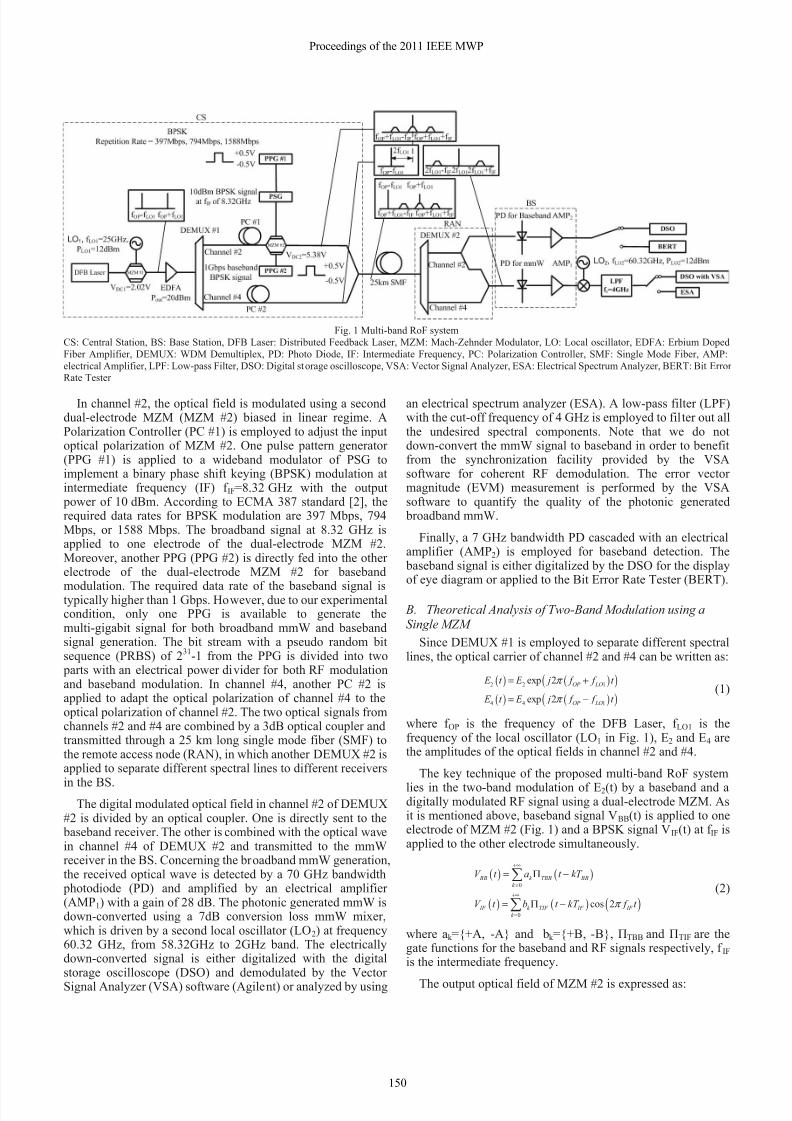
The electrical spectrum and constellation diagram for 1588Mbps data rate signal are shown in Fig. 2. EVM of the
broadband mmW with and without baseband modulation,which are compared with the EVM requirements according toECMA 387 standard, are reported in Tab. I.
0 1 2 3 4
-90
-80
-70
-60
-50
-40
-30
-20
P o w e r [ d B m ]
Frequency [GHz]
Contellation Diagram
Fig 2 Measurement results of photonic generated 1588Mbps mmW after
electrical down-conversion. inset: BPSK constellation diagram
Tab. IPower and EVM measurements after electrical down-conversion compared
with the requirements of ECMA 387 standard
(i) ECMA387 requirements for transmitter and receiver
Data Rate (Mbps) 397 794 1588
Maximum emitted power(dBm)
10 10 10
Receiver sensitivity (dBm) -60.0 -57.0 -50.5
Maximum allowed EVM (%) 33.4 23.7 11.2
(ii) Broadband mmW with baseband signalData Rate (Mbps) 397 794 1588
Power after down-conversion(dBm)
-37.1 -37.3 -37.7
Received Power at 58.32 GHz(dBm)
-30.1 -30.3 -30.7
Receiver sensitivity (dBm) -23 -23 -23
EVM (%) 8.6 10.6 14.6
(iii) Broadband mmW without baseband signal
Data Rate (Mbps) 397 794 1588
Power after down-conversion(dBm)
-37.1 -37.3 -37.7
Received Power at 58.32 GHz(dBm)
-30.1 -30.3 -30.7
EVM (%) 8.6 10.7 14.6
Comparing Tab. I (ii) and (iii), it is obvious that there is noimpact from the baseband modulation to the mmW signal,which agrees with the theoretical conclusions drawn in sectionII. B. EVM values are in the limit of the ECMA 387 standard toinsure error free transmission [2] except for the 1588 Mbps datarate. EVM measurements for the optical generated broadbandmmW at 397 Mbps and 794 Mbps meet the requirements of theECMA 387 standard with a large margin (Tab. I (i) and (ii)).Due to 7 dB down-conversion loss of the mixer and the -30dBm sensitivity of the DSO, the sensitivity of the receiver,including the mixer and DSO, can be evaluated to -23 dBm,which is not low enough compared to the ECMA 387 standard.The power of the photonic generated 1588 Mbps signal isaround -30.7 dBm, which is far below the authorized maximum
power of 10 dBm [8] and even much lower than the sensitivity
151
Proceedings of the 2011 IEEE MWP

8/13/2019 Convergence of Radio systems with Fiber
http://slidepdf.com/reader/full/convergence-of-radio-systems-with-fiber 4/4
of the receiver. We expect that an additional higher gainlow-noise amplifier (LNA) at receiver input (Fig. 1) couldimprove again the quality of the broadband mmW.
B. Baseband Signal Measurements
In the proposed multi-band RoF system, DEMUX #2 in theRAN is employed to separate different spectral lines todifferent receivers (Fig. 1). However, only one DEMUX(DEMUX #1) is available due to the limitation of ourexperimental condition. Therefore, channel #4 of DEMUX #1is cut-off during the baseband signal detection in theexperiment. We expect an additional DEMUX as DEMUX #2to realize the multiuser system as we proposed in section II.
(a) Two-band modulation: baseband signal and mmW
(b) Single band modulation: baseband signal without mmW
Fig. 3 Eye diagrams of the baseband signal with single band and two-bandmodulation configurations
-11
-10
-9
-8
-7
-6
-5
-4
-3
-17 -16 -15 -14 -13 -12 -11 -10
l o g 1 0
( B E R )
Two-band modulation
Recieved Optical Power [dBm]
Single Baseband Modulation
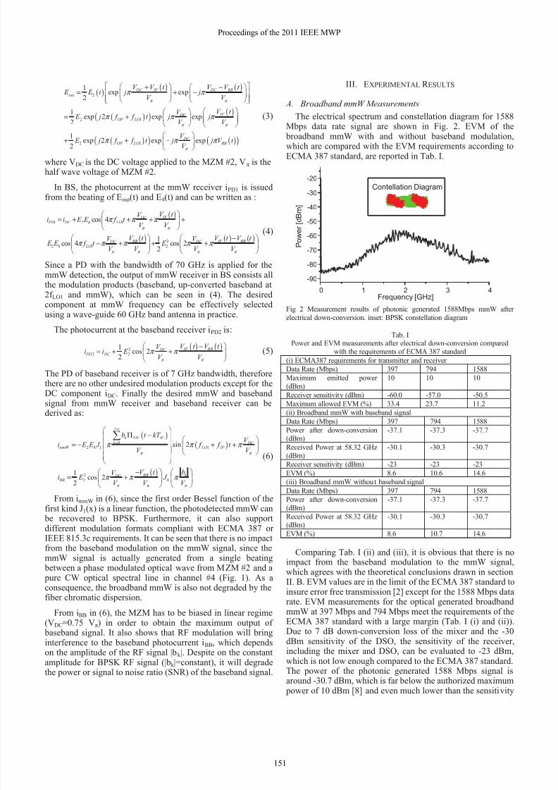
Fig. 4 BER measurement as a function of received optical power for single band and two-band modulation configurations.
Fig. 3 (a) and (b) show the eye diagrams of 1 Gbps basebandsignal with or without 1 Gbps RF signal modulationrespectively. Comparing Fig. 3 (a) and (b), owing to the impactof the RF modulation induced by MZM #2 (Fig. 1), it can beseen that the baseband signal loses 11% of amplitude, whichamounts to 1 dB loss in electrical power. Fig. 4 shows themeasured BERs as a function of the received optical power forthe single baseband modulation and two-band modulation.From Fig. 4, the difference between the received optical powerin the case of signal baseband modulation and two-bandmodulation, for the same BER value, is around 0.5 dB, whichamounts to 1 dB electrical power as well.
During the experiment, 10 dBm BPSK signal at 8.32 GHz is
applied to the MZM #2 (Fig. 1), therefore the amplitude of thesignal |bk | is B=1 V. Considering B=1 and V=4.83V to iBB (6),
it is possible to calculate the power degradation on iBB induced by the RF modulation. The baseband signal will lose 10%amplitude, which amounts to 1 dB in power. This agrees withthe result of eye diagrams and BERs. Despite on the impact ofRF modulation, the baseband signal with low BER (<10 -9) has been transmitted over 25 km long SMF by our system.
IV. CONCLUSION
A RoF system for wireline and wireless transmissioncompatible with both broadband BPSK mmW for ECMA 387standard and 1 Gbps baseband signal for FTTH application has been demonstrated in this paper. The digital signal modulationsfor mmW and baseband signal are implemented by using asingle dual-electrode MZM. This technique is compatible withWDM-RoF scheme to feed multiple BSs. Despite the lowoutput power of the broadband mmW, 1588 Mbps BPSK signalat 60GHz band with the EVM as low as 14.6% has beengenerated by photonic up-conversion without any interferencefrom the baseband signal modulation and any impact of
chromatic dispersion after 25 km long fiber transmission.Baseband signal with the BER lower than 10 -9 has beentransmitted simultaneously. Furthermore, the interference fromRF signal modulation to the baseband signal has beenquantified by theoretical approach and experiment. It has beenshown that for constant envelope RF modulation such as BPSK,the degradation of baseband signal induced by the RFmodulation is limited to be lower than 1 dB electrical power,considering a high MZM input RF modulation power of 10dBm, in our system.
R EFERENCES
[1] Y. Le Guennec, G. Maury, B. Cabon and J. Yao, “Up-Conversion of IQ
Modulated Subcarriers with Dispersive Fiber for 60 GHzRadio-Over-Fiber Networks,” International Symposium on Microwave
Photonics, Oct.2006. [2] http://www.ecma-international.org/publications/standards/Ecma-387.htm.[3] IEEE Std 802.15.3c-2009 (Amendment to IEEE Std 802.15.3-2003), pp.
c1-187, 2009.[4] K. Prince, J. B. Jensen, A. Caballero, X. B. Yu, T. B. Gibbon, D. Zibar, N.
Guerrero, A. V. Osadchiy, and I. T. Monroy, "Converged Wireline andWireless Access Over a 78-km Deployed Fiber Long-Reach WDM PON,"
Ieee Photonics Technology Letters, vol. 21, pp. 1274-1276, Sep 2009.[5] P. Tien-Thang, Y. Xianbin, T. B. Gibbon, L. Dittmann, and I. T. Monroy,
"A WDM-PON-Compatible System for Simultaneous Distribution ofGigabit Baseband and Wireless Ultrawideband Services With FlexibleBandwidth Allocation," Photonics Journal, IEEE, vol. 3, pp. 13-19, 2011.
[6] W. Yong-Yuk, K. Hyun-Seung, S. Yong-Hwan, and H. Sang-Kook, "FullColorless WDM-Radio Over Fiber Access Network SupportingSimultaneous Transmission of Millimeter-Wave Band and Baseband
Gigabit Signals by Sideband Routing," Lightwave Technology, Journal of,vol. 28, pp. 2213-2218, 2010.
[7] J. J. Vegas Olmos, T. Kuri, and K. Kitayama, "ReconfigurableRadio-Over-Fiber Networks: Multiple-Access Functionality Directly Overthe Optical Layer," Microwave Theory and Techniques, IEEETransactions on, vol. 58, pp. 3001-3010, 2010.
[8] Z. Jia, J. Yu, A. Chowdhury, G. Ellinas, and G. Chang, "SimultaneousGeneration of Independent Wired and Wireless Services Using a SingleModulator in Millimeter-Wave-Band Radio-Over-Fiber Systems,"
Photonics Technology Letters, IEEE, vol. 19, pp. 1691-1693, 2007.[9] P. X. a. A. V. Su-Khiong Yong, "60 GHz Technology for Gbps WLAN and
WPAN: From Theory to Practice," John Wiley & Sons, Ltd, 2011.
152
Proceedings of the 2011 IEEE MWP