Embed Size (px)
Citation preview

Controller with internal Quad-band GSM/GPRS/3G modem
MCL 5.10
User manual
Version 1.3
ELGAMA SISTEMOS Ltd Lithuania 2015
2
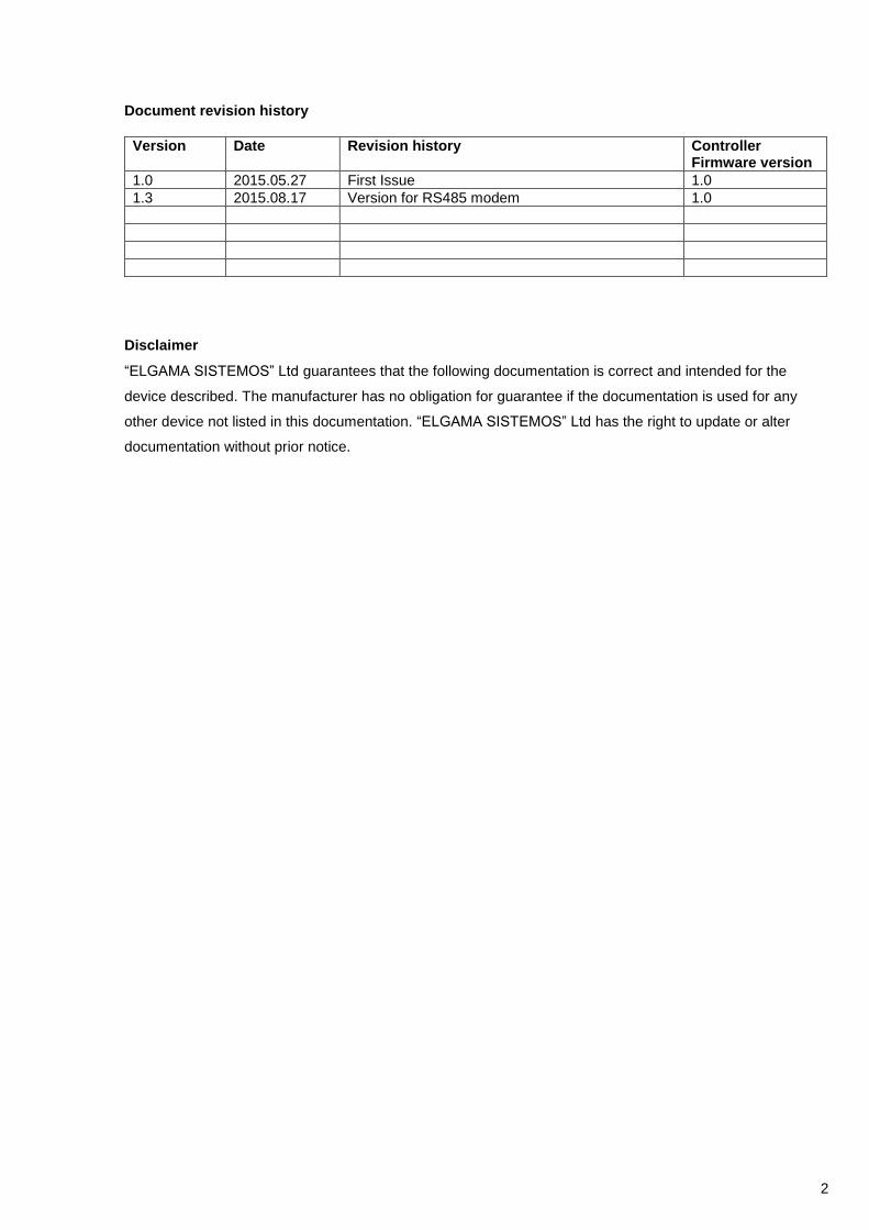
Document revision history
Version Date Revision history Controller Firmware version
1.0 2015.05.27 First Issue 1.0
1.3 2015.08.17 Version for RS485 modem 1.0
Disclaimer
“ELGAMA SISTEMOS” Ltd guarantees that the following documentation is correct and intended for the
device described. The manufacturer has no obligation for guarantee if the documentation is used for any
other device not listed in this documentation. “ELGAMA SISTEMOS” Ltd has the right to update or alter
documentation without prior notice.

3
1.2. Contents
DOCUMENT REVISION HISTORY ................................................................................................................... 2
1.2. CONTENTS ............................................................................................................................................ 3
1.3. SIGNS AND ABBREVIATIONS ............................................................................................................. 4
1.4. SAFETY INSTRUCTIONS ..................................................................................................................... 5
2. APPLICATION AND FUNCTIONALITY ..................................................................................................... 6
2.1. GENERAL INFORMATION ................................................................................................................... 6
2.2. SUPPORTED COMMUNICATION PROTOCOLS ................................................................................. 6
2.3. CONFIGURATION ................................................................................................................................. 6
3. PRINCIPAL COMPONENTS OF THE CONTROLLER MCL 5.10 ............................................................. 7
4. TECHNICAL CHARACTERISTICS ............................................................................................................ 7
5. CONNECTING INTERFACES .................................................................................................................... 8
5.1. CONNECTING POWER CABLE TO THE MCL 5.10 ............................................................................ 8
5.2. CONNECTING METER/METERS RS485.............................................................................................. 9
5.2.1. CONNECTING A METER OVER RS485 ........................................................................................... 9
5.3. LABELING ............................................................................................................................................. 9
6. PARAMETERIZATION GUIDE................................................................................................................. 10
6.1. INITIAL INFORMATION ...................................................................................................................... 10
6.2. PROCEDURE OF LOCAL PARAMETERIZATION ............................................................................. 10
7. PARAMETERIZATION ............................................................................................................................. 15
7.1. SECURITY ........................................................................................................................................... 15
7.2. DEFAULT PASSWORD ...................................................................................................................... 15
7.3. APN ...................................................................................................................................................... 15
7.4. AUTOMATIC REBOOT ....................................................................................................................... 15
7.5. 2G/3G MODE ....................................................................................................................................... 15
7.6. FIRMWARE UPDATE .......................................................................................................................... 15
7.6.1. AUTOMATIC FIRMWARE UPDATE ............................................................................................... 15
7.6.2. MANUAL FIRMWARE UPDATE ..................................................................................................... 15
7.7. BYTE W. TIMEOUT IN X BYTES ........................................................................................................ 15
7.9. GRANT MENU INTERFACE ................................................................................................................... 15
8. EVENT LOG ............................................................................................................................................. 16
8.1. EVENT LOG RECORD FORMAT ........................................................................................................ 16
8.2. LOGGING EVENTS ............................................................................................................................. 16
9. ANNEX A. CONTROLLER MENU AND CONFIGURATION SETTINGS ................................................... 17
10. ANNEX B. MANUFACTURER’S GUARANTEE ....................................................................................... 21
4
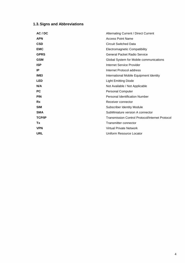
1.3. Signs and Abbreviations
AC / DC Alternating Current / Direct Current
APN Access Point Name
CSD Circuit Switched Data
EMC Electromagnetic Compatibility
GPRS General Packet Radio Service
GSM Global System for Mobile communications
ISP Internet Service Provider
IP Internet Protocol address
IMEI International Mobile Equipment Identity
LED Light Emitting Diode
N/A Not Available / Not Applicable
PC Personal Computer
PIN Personal Identification Number
Rx Receiver connector
SIM Subscriber Identity Module
SMA SubMiniature version A connector
TCP/IP Transmission Control Protocol/Internet Protocol
Tx Transmitter connector
VPN Virtual Private Network
URL Uniform Resource Locator
5
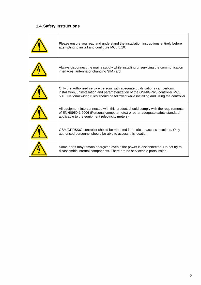
1.4. Safety Instructions
Please ensure you read and understand the installation instructions entirely before attempting to install and configure MCL 5.10.
Always disconnect the mains supply while installing or servicing the communication interfaces, antenna or changing SIM card.
Only the authorized service persons with adequate qualifications can perform installation, uninstallation and parameterization of the GSM/GPRS controller MCL 5.10. National wiring rules should be followed while installing and using the controller.
All equipment interconnected with this product should comply with the requirements of EN 60950-1:2006 (Personal computer, etc.) or other adequate safety standard applicable to the equipment (electricity meters).
GSM/GPRS/3G controller should be mounted in restricted access locations. Only authorised personnel should be able to access this location.
Some parts may remain energized even if the power is disconnected! Do not try to disassemble internal components. There are no serviceable parts inside.

6
2. Application and Functionality
2.1. General Information
MCL 5.10 controller (further referred to as a controller) is used in AMR systems for automated remote data reading of electricity, heat meters and other electronic devices and data transmission to remote offices. Device does not store, manipulate or alter meter information. The controller has an internal lithium-polymer battery for power failure notification to the remote data center. GSM radio network with CSD/GPRS/2G/3G technology and TRANSPARENT DATA, TCP/IP protocols is used for data transmission to the management system.
2.2. Supported Communication Protocols
Controller supports two-direction data exchange with Elgama Sistemos system HES (communication protocols IEC 62056-31, DLMS/COSEM (all security layers as well)).
2.3. Configuration
RS485 electric communication interfaces are used for meter data read-out (fixed net baud rate of 300...115200 bauds, 8N1 or 7E1 bytes). Device parameterization can be performed locally via RS232 interfaces or remotely via SMS or GSM/GPRS. Controller supports both TCP/IP server and client connection modes.
2.4. Mounting and power supply
Controller supports and is mounted (can be replaced) in the terminal covers of electricity meters manufactured by “Elgama-Elektronika” or on the DIN rail. When mounted properly, all of the modem indicators are visible. The controller is powered by the external power source from the meter using connection socket X1 of the controller MCL 5.10. The controller has an internal lithium-polymer battery for power failure notification to the remote data center.
2.5. Firmware and settings update The controller firmware can be updated locally (via RS232) and remotely (using GPRS connection). Aditionally, multiple controllers can be updated (updates involve managing controllers’ parameters, reading values, firmware updates) using the software provided. There is possible to integrate new protocols and types of meters in new firmware versions. After power on, if the configuration is set to automatic update, the controller checks if there is the newer firmware version and automatically updates it’s firmware. Contact the manufacturer for the new firmware and tools for firmware upgrades.
2.6. Mobile network signal strength monitor
The controller periodically tries to download GPRS data from the network. If download fails, the controller restarts the connection. When controller powers on, the device automatically tries to connect to the 3G network and measures signal strength. When the signal is weaker than the parameter described in the configuration, the controller changes connection to the 2G/GPRS. The controller automatically connects to the 3G network only after reboot.
2.7 Automatic provider detection When the SIM card is placed in the controller and controller is powered on, the system checks if the SIM card’s prrovider’s ID matches settings described in the configuration Providers’ menu. If so, the controller automatically uses described providers settings. The providers ID and other options can be set using controllers menu or via parametrization software in “provider settings”.
2.8 Alarm system (Plug & Play) When any event or alarm is received from the meter to the controller, the controller sends all the data received from the meter and the controllers information (IMEI, IP) using http protocol to the url address specified in the settings menu “Plug&Play server address”.
7
2.9 Time synchronization The controller synchronizes time with GSM network provider. The device’s time zone can be set and changed in the Device configuration menu. The current time is used for audit and event logging.
2.10 Meter check The controller periodically tries to communicate with the meter. The result of the communication is saved to the controllers memory and can be read by HES using OBIS code.
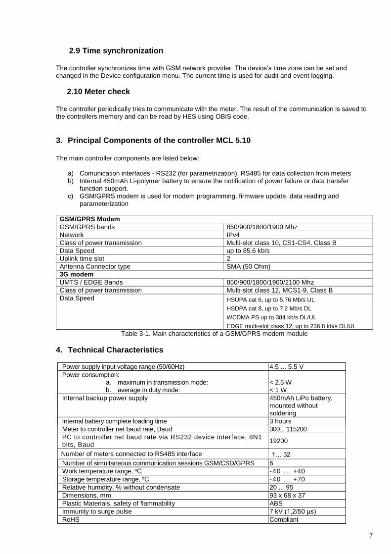
3. Principal Components of the controller MCL 5.10
The main controller components are listed below:
a) Comunication interfaces - RS232 (for parametrization), RS485 for data collection from meters b) Internal 450mAh Li-polymer battery to ensure the notification of power failure or data transfer
function support. c) GSM/GPRS modem is used for modem programming, firmware update, data reading and
parameterization
GSM/GPRS Modem
GSM/GPRS bands 850/900/1800/1900 Mhz
Network IPv4
Class of power transmission Multi-slot class 10, CS1-CS4, Class B
Data Speed up to 85.6 kb/s
Uplink time slot 2
Antenna Connector type SMA (50 Ohm)
3G modem
UMTS / EDGE Bands 850/900/1800/1900/2100 Mhz
Class of power transmission Multi-slot class 12, MCS1-9, Class B
Data Speed HSUPA cat 6, up to 5.76 Mb/s UL
HSDPA cat 8, up to 7.2 Mb/s DL
WCDMA PS up to 384 kb/s DL/UL
EDGE multi-slot class 12, up to 236.8 kb/s DL/UL
Table 3-1. Main characteristics of a GSM/GPRS modem module
4. Technical Characteristics
Power supply input voltage range (50/60Hz) 4.5 ... 5.5 V
Power consumption: a. maximum in transmission mode: b. average in duty mode:
< 2.5 W < 1 W
Internal backup power supply 450mAh LiPo battery, mounted without soldering
Internal battery complete loading time 3 hours
Meter to controller net baud rate, Baud 300... 115200
PC to controller net baud rate via RS232 device interface, 8N1 bits, Baud
19200
Number of meters connected to RS485 interface 1… 32
Number of simultaneous communication sessions GSM/CSD/GPRS 6
Work temperature range, оС -40 . . . +40
Storage temperature range, оС -40 . . . +70
Relative humidity, % without condensate 20 ... 95
Dimensions, mm 93 x 68 x 37
Plastic Materials, safety of flammability ABS
Immunity to surge pulse 7 kV (1,2/50 µs)
RoHS Compliant

8
MCL 5.10 LV
Antenna SMA
Table 4-1. MCL 5.10 controller technical characteristics
Table 4-2 MCL 5.10 controller indicators description
Operation and received signal strength indication – RGB LED1: - Not registered to GSM network / no SIM card - Registered to GSM/GPRS network; - Registered to 3G network
Signal strength indication*: -113 to -82 dBm or less -81 to -70 dBm -69 to -51dBm or more
- GSM/GPRS data session active; (connection established)
R long pulse (0,4 Hz /1s) G pulse G double pulse R pulse (0,4 Hz) B pulse (0,4 Hz) G pulse (0,4 Hz) Same color more frequent pulse (2Hz)
Interface activity / battery charge indication – RGB LED 2: - Data transfer; active interface: RS485
B- query / respond
Table 4-2. *Default values indicated. Signal strength is check every 20 seconds. Signal indication level can be changed in the Menu
Note! The controller is powered on if any of the indicator defining signal strength is on (pulse).
5. Connecting interfaces
Important: Before proceeding, please ensure the device will remain clean and dry during the installation and no liquid or other substance will remain inside as that could severely affect device performance and warranty.
Important: PIN code of a SIM card must be disabled prior the installation
Pin X1 X2
1. RS232 GND Power GND
2. RS232 TX Power GND
3. RS232 RX RS485 B
4. - RS485 A
5. - +5V
6. - +5V
MCL 5.10 pinout from top to bottom
5.1. Connecting power cable to the MCL 5.10
On the side of the controller there is two type RJ11 connectors. The controller is powered on by the external power supply from the meter connecting the RJ11 plug from the power source to the X2 socket of the controller (see the pinout above).
LED 1
LED 2
RS485 / Power
RS232
X2 X1

9
5.2. Connecting Meter/Meters RS485
5.2.1. Connecting a Meter Over RS485
In order to connect a meter, please connect controller’s X2 connector with a meter’s “A” and “B” socket of the RS485 interface (see Figure 4.2-1). If there is more than one meter to be connected the parallel method must be used as indicated below:
5.3. Labeling
Principal controller information is marked on a label. Label explanation: • LED indicator position • Controller name • Power supply input and consumption characteristics • Unique identification number (ID) • Unique identification number (Barcode), type: Interleaved 2/5
Figure 4.3.1-1. Meter connection to RS485 interface
123 kWh 125 kWh 124 kWh
MCL 5.10 LV
X2
A
RS485
B
A
A
RS485
B
B
A
RS485
B
Meters 1 .. 32, parallel connection method

10
6. Parameterization Guide
6.1. Initial Information
MCL 5.10 controller using GPRS technology transmits the data of measurement equipment (meters). There is
an internal modem with a SIM card socket (SIM card is inserted in the back of the controller. Open the
separeted pard and place the sim card).
Connect the controller to the computer‘s COM or USB (depending on connection) port to start the setup.
Connect the antenna before switching the controller on. It is not necessary to insert a SIM card for
parameterization. If there is an ongoing data readout, it must be interrupted before parameterization.
6.2. Procedure of Local Parameterization
Access to the controller can be protected by a password. Several levels of users are possible: different admin
logins and user login. Each login has separate menus and control functions. Parameterization can be handled
using HyperTerminal (Figure 6.2-1, Figure 6.2-2) or other software allowing connecting MCL 5.10 via device’s
RS232 interface.
After parameterization user must restart the controller's using the reset function in the menu.
You need to have the proper cable to connect from the X1 port on the device to the RS232 port or the USB port of the computer
Local program for parametrization Hyperterminal is freeware from manufacturer Microsoft. Supported OS: Windows XP , Windows Vista, Windows7 and later. Download from: http://downloads.elgsis.com/hyperterm.zip
Important: Parameterization may vary depending on connection interface type, device version, administrator’s PC operating system region and version. Therefore figures and menus given below may differ from actual due to software updates and upgrades.
Important: It is required to disable PIN request on a SIM card, before inserting it in the controller’s SIM socket
The settings of a COM port for parameterization are independent from the settings for the data readout and the default settings are set as follows: 19200 bps, parity - none, 8 data bits and flow control - none.
Important! To load or re-load controller’s menu press button ESC (on keyboard) 3 times.

11
Enter a name for the new connection (Figure 6.2-1)
Figure 6.2-1
Select a port MCL is connected to (Figure 6.2-2)
Figure 6.2-2
After pressing OK in the COM Properties window (figure 6.2-3), the settings are set to Auto detect by default (figure 6.2-4).
Figure 6.2-3 Select port settings
12
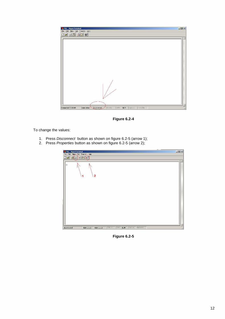
Figure 6.2-4
To change the values:
1. Press Disconnect button as shown on figure 6.2-5 (arrow 1); 2. Press Properties button as shown on figure 6.2-5 (arrow 2);
Figure 6.2-5

13
3. Press Configure button as shown on figure 6.2-6 (arrow 3);
4. Press OK button as shown on figure 6.2-6 (arrow 4);
Figure 6.2-6
5. Important. Ensure that other settings of the connection are set as shown on figures 6.2-7;
Figure 6.2-7
14
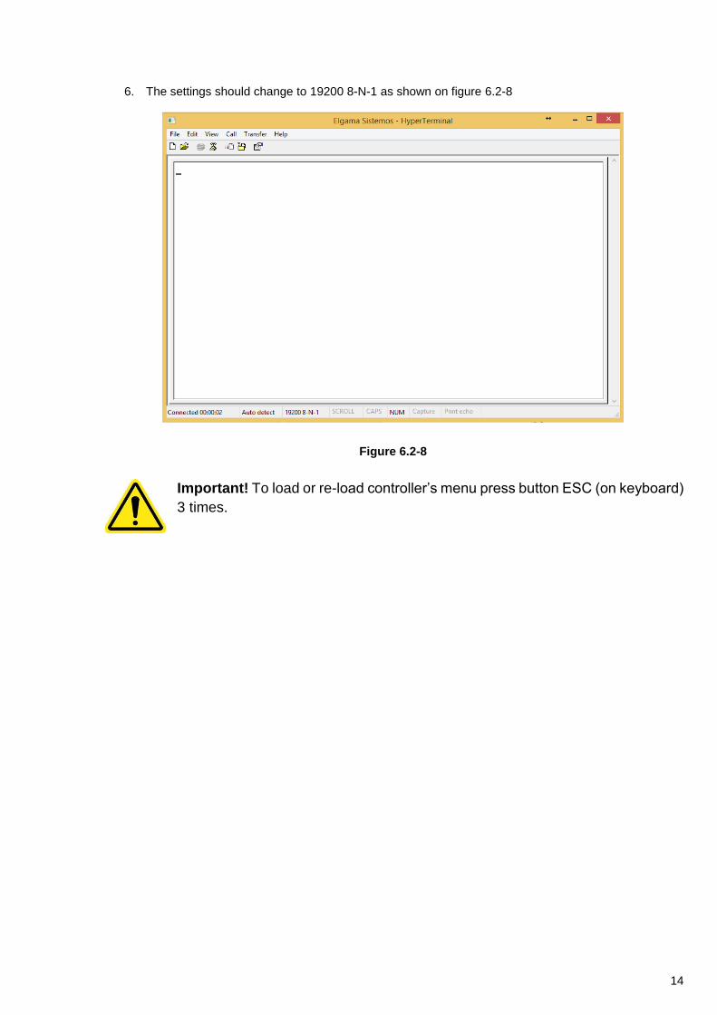
6. The settings should change to 19200 8-N-1 as shown on figure 6.2-8
Figure 6.2-8
Important! To load or re-load controller’s menu press button ESC (on keyboard)
3 times.
15
7. Parameterization
The entire MCL 5.10 menu hierarchy is described in an Annex A. “Controller menu and configuration settings”. Main device functions are further described below.
7.1. Security
Controller parameterization menus are protected with dedicated passwords to prevent from unauthorised access and configuration.
7.2. Default Password
There are two user levels: admin and user where admin is superior. Default admin password is “admin”. Default user password is “user”. Each login has separate menus and control functions. If required, a different default passwords can be set automatically during the manufacturing process. Alternatively, default passwords can be changed manually or automatically.
7.3. APN
APN names and settings (GSM Provider/Network ID, DNS etc) for each APN are entered by administrator or imported via sms and can be accessed via configuration menu. Each separate APN has different numbers and IP address lists and every other APN can be configured manually.
7.4. Automatic Reboot
The device configuration allows to set an interval in minutes to enable automatic device reboot (restart) when idle, without having an engineer to interfere. The reboot command may also be sent manualy using SMS or parametrization menu.
7.5. 2G/3G mode
The device can work select the 2G or the 3G mode automatically depending on the best quality or it can be done remotely in menu item Provider settings, Provider network mode.
7.6. Firmware update
The firmware can be set to be updated automatically or manually.
7.6.1. Automatic Firmware Update
If set to automatic, after restart controller will attempt automatic firmware download and update from the IP (IP of a FTP server) address indicated in the APN setting for a specific APN used.
7.6.2. Manual Firmware update
Depending on the client’s end system configuration, controller modification and settings, controller can support manual firmware update via GSM/GPRS or via USB, RS232 by directly connecting the controller to a PC. “Elgama Sistemos” proprietary firmware update tool or alternative software can be used when required.
7.7. Byte w. timeout in X bytes
Timeout value defined in byte transfer time (it depends on baud rate) multiplied by this setting value. Timeout is set after each received byte in frame. If timeout expires after the last received byte, the frame is adopted.
7.9. Grant menu interface
The controller menu can be reached using several interfaces: Wireless, RS485, RS232, USB (depending on the modification). Each menu interface can be enabled (granted) or disabled. To enable interface for controller configuration, set the menu option for the interface value “Grant interface – false”. For example, to disable RS485 menu interface, go to the RS485 out configuration and set the value “Grant menu interface” to false.

16
8. Event Log
8.1. Event Log Record Format
Each event log record will register the following information:
Date and time of the event (if known)
Type of the event
Subject identity and/or source of the event
Outcome of the event
8.2. Logging Events
Controller logs the following events:
Failed authorization or authentication
Requests or commands received
Firmware update/information
High number of malformed or unexpected messages and errors
Power supply recovery events
Unauthenticated communication All events logs can be enabled/disabled if required. If event log is disabled, event alert is disabled as well.
17
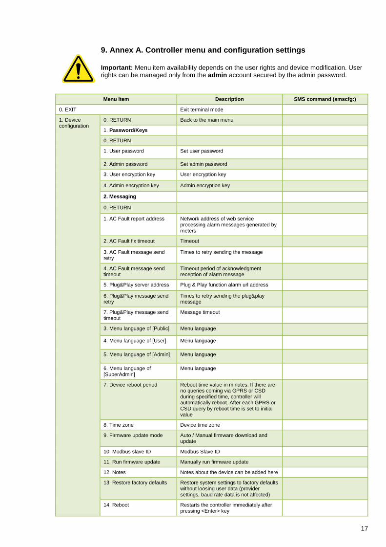
9. Annex A. Controller menu and configuration settings
Important: Menu item availability depends on the user rights and device modification. User rights can be managed only from the admin account secured by the admin password.
Menu Item Description SMS command (smscfg:)
0. EXIT Exit terminal mode
1. Device configuration
0. RETURN Back to the main menu
1. Password/Keys
0. RETURN
1. User password Set user password
2. Admin password Set admin password
3. User encryption key User encryption key
4. Admin encryption key Admin encryption key
2. Messaging
0. RETURN
1. AC Fault report address Network address of web service processing alarm messages generated by meters
2. AC Fault fix timeout Timeout
3. AC Fault message send retry
Times to retry sending the message
4. AC Fault message send timeout
Timeout period of acknowledgment reception of alarm message
5. Plug&Play server address Plug & Play function alarm url address
6. Plug&Play message send retry
Times to retry sending the plug&play message
7. Plug&Play message send timeout
Message timeout
3. Menu language of [Public] Menu language
4. Menu language of [User] Menu language
5. Menu language of [Admin] Menu language
6. Menu language of [SuperAdmin]
Menu language
7. Device reboot period 0.
Reboot time value in minutes. If there are no queries coming via GPRS or CSD during specified time, controller will automatically reboot. After each GPRS or CSD query by reboot time is set to initial value
8. Time zone Device time zone
9. Firmware update mode Auto / Manual firmware download and update
10. Modbus slave ID Modbus Slave ID
11. Run firmware update Manually run firmware update
12. Notes Notes about the device can be added here
13. Restore factory defaults Restore system settings to factory defaults without loosing user data (provider settings, baud rate data is not affected)
14. Reboot Restarts the controller immediately after pressing <Enter> key
18
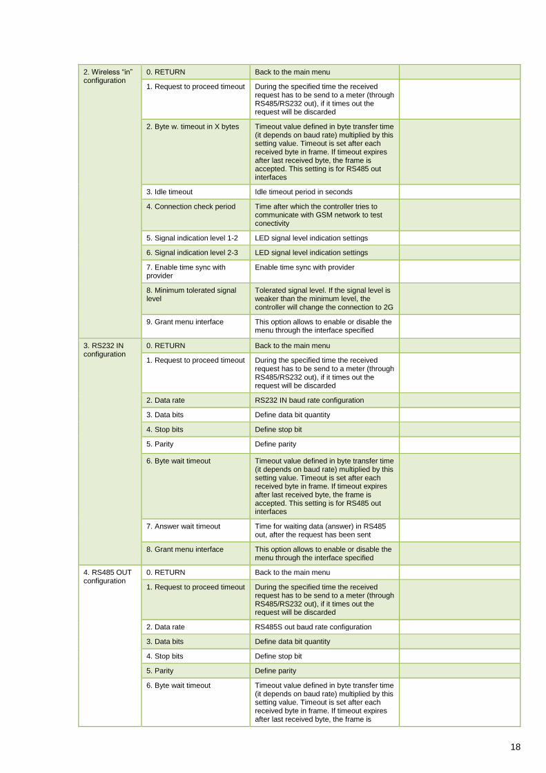
2. Wireless “in” configuration
0. RETURN Back to the main menu
1. Request to proceed timeout
During the specified time the received request has to be send to a meter (through RS485/RS232 out), if it times out the request will be discarded
2. Byte w. timeout in X bytes
Timeout value defined in byte transfer time (it depends on baud rate) multiplied by this setting value. Timeout is set after each received byte in frame. If timeout expires after last received byte, the frame is accepted. This setting is for RS485 out interfaces
3. Idle timeout Idle timeout period in seconds
4. Connection check period Time after which the controller tries to communicate with GSM network to test conectivity
5. Signal indication level 1-2 LED signal level indication settings
6. Signal indication level 2-3 LED signal level indication settings
7. Enable time sync with provider
Enable time sync with provider
8. Minimum tolerated signal level
Tolerated signal level. If the signal level is weaker than the minimum level, the controller will change the connection to 2G
9. Grant menu interface This option allows to enable or disable the menu through the interface specified
3. RS232 IN configuration
0. RETURN Back to the main menu
1. Request to proceed timeout
During the specified time the received request has to be send to a meter (through RS485/RS232 out), if it times out the request will be discarded
2. Data rate RS232 IN baud rate configuration
3. Data bits Define data bit quantity
4. Stop bits Define stop bit
5. Parity Define parity
6. Byte wait timeout Timeout value defined in byte transfer time (it depends on baud rate) multiplied by this setting value. Timeout is set after each received byte in frame. If timeout expires after last received byte, the frame is accepted. This setting is for RS485 out interfaces
7. Answer wait timeout Time for waiting data (answer) in RS485 out, after the request has been sent
8. Grant menu interface This option allows to enable or disable the menu through the interface specified
4. RS485 OUT configuration
0. RETURN Back to the main menu
1. Request to proceed timeout
During the specified time the received request has to be send to a meter (through RS485/RS232 out), if it times out the request will be discarded
2. Data rate RS485S out baud rate configuration
3. Data bits Define data bit quantity
4. Stop bits Define stop bit
5. Parity Define parity
6. Byte wait timeout Timeout value defined in byte transfer time (it depends on baud rate) multiplied by this setting value. Timeout is set after each received byte in frame. If timeout expires after last received byte, the frame is
19
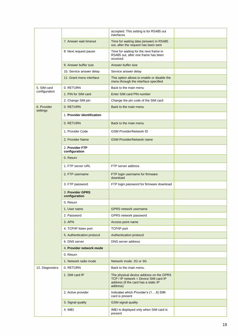
accepted. This setting is for RS485 out interfaces
7. Answer wait timeout Time for waiting data (answer) in RS485 out, after the request has been sent
8. Next request pause Time for waiting for the next frame in RS485 out, after one frame has been received
9. Answer buffer size Answer buffer size
10. Service answer delay Service answer delay
11. Grant menu interface This option allows to enable or disable the menu through the interface specified
5. SIM card configuration
0. RETURN Back to the main menu
1. PIN for SIM card Enter SIM card PIN number
2. Change SIM pin Change the pin code of the SIM card
6. Provider settings
1. 0. RETURN Back to the main menu
2. 1. Provider identification
3. 0. RETURN Back to the main menu
4. 1. Provider Code GSM Provider/Network ID
5. 2. Provider Name GSM Provider/Network name
6. 2. Provider FTP configuration
7. 0. Return
8. 1. FTP server URL FTP server address
9. 2. FTP username FTP login username for firmware download
10. 3. FTP password FTP login password for firmware download
11. 3. Provider GPRS configuration
12. 0. Return
13. 1. User name GPRS network username
14. 2. Password GPRS network password
15. 3. APN Access point name
16. 4. TCP/IP listen port TCP/IP port
17. 5. Authentication protocol Authentication protocol
18. 6. DNS server DNS server address
19. 4. Provider network mode
20. 0. Return
21. 1. Network radio mode Network mode: 2G or 3G
12. Diagnostics 1. 0. RETURN Back to the main menu.
2. 1. SIM card IP The physical device address on the GPRS TCP / IP network = Device SIM card IP address (if the card has a static IP address)
3. 2. Active provider Indicates which Provider’s (1….6) SIM card is present
4. 3. Signal quality GSM signal quality
5. 4. IMEI IMEI is displayed only when SIM card is present
20
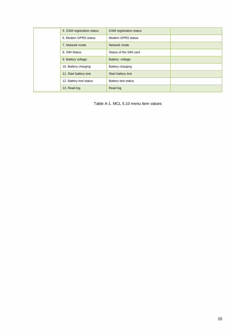
Table A-1. MCL 5.10 menu item values
6. 5. GSM registration status GSM registration status
7. 6. Modem GPRS status Modem GPRS status
8. 7. Network mode Network mode
9. 8. SIM Status Status of the SIM card
9. Battery voltage Battery voltage
10. Battery charging Battery charging
11. Start battery test Start battery test
12. Battery test status Battery test status
10. 13. Read log Read log
21
10. Annex B. Manufacturer’s Guarantee
“ELGAMA SISTEMOS” Ltd guarantees that materials used in controller manufacturing process, its parts and
assembly are of a good quality. During the guarantee period, manufacturer ensures uninterrupted performance
of the device only if it was installed and serviced by the authorized “ELGAMA SISTEMOS” Ltd representative
or licenced engineer if they are strictly following the installation and configuration procedures described in the
manual. In case of a power cut, manufacturer ensures, that AMR (Automatic Meter Reading) system equipment
manufactured by “ELGAMA SISTEMOS” Ltd will not have any influence on the electricity meter’s data. MCL
5.10 system will restart automatically and will start operating as normal as soon as the voltage is restored.
The manufacturer has no obligation to service under the guarantee and provide free service in the following
cases:
If communication lines were cut off or were shortened, if they were connected to telephone lines or
any other lines or wires that do not belong to the relevant AMR system;
If the producer of the system was not informed about the change of structure or AMR scheme, the
change of electricity meters, their installation spot or parameterization data. Consent for structure or
AMR scheme change has to be given. The manufacturer has no obligation for guarantee and to
provide free service if any damage to the AMR system is produced.
If the informational stickers and seals, attached to its containing parts or case, were broken.