Embed Size (px)
Citation preview
KIT NO. 9012711, 9012712, 9012713 Page 1 of 5
9012723 Rev. 01 (10- 19) Tennant Company www.tennantco.com
Controller Replacement KitModels: Tennant T7 / Nobles Speed Scrub Rider
This kit includes the necessary parts to replace a defective controller board on a T7/Speed Scrub Rider.
INSTALLATION INSTRUCTIONS:Installation Time: 1.5 Hours
TOOLS REQUIRED: Torque Wrench, 8mm, 10mm and13mm sockets, Wire Cutters, Insulated and Standard WireTerminal Crimping Tool and Heat Gun.
PREPARATION
1. Park the machine on a level surface.
2. Turn the machine off and remove the key.
FOR SAFETY: Before servicing machine, stop onlevel surface, set parking brake, turn offmachine, and remove key.
3. Disconnect the black (- ) battery cable frombattery pack.
FOR SAFETY: When servicing machine,disconnect battery connection before workingon machine.
4. Disconnect the wire harness from the operatorseat switch and remove the seat from themachine.
5. Remove the battery compartment shroud fromthe machine.
INSTALLATION1. Remove the electrical panel cover from the
controller. Six bolts secure panel in place.
2. Disconnect the controller wire harnessconnectors and the red (+) and black (- ) cablesfrom old circuit board. Remove the screw thatmounts the controller panel tab to machine anddispose the old controller.
Tab
3. For early models: If the machine’s controllerwire harness is equipped with the circledconnector, replace connector with the suppliedharness connector adapter as described below.The new controller board requires the upgradedconnector.
Cut and strip thebrown/12 & pink/11wires.
Strip wires 3/8”(9.5 mm)
Connect the supplied harness connectoradapter to the cut wires. Use aninsulated terminal crimping tool. Seal theterminal connectors with a heat gun.
Controllerharnessconnector
Upgraded Connector
4. For models manufactured before the followingserial numbers perform this step:s/n 10426042 - North America/Int’l modelss/n T7xxx03593 - Europe disk models/n T7xxx02819 - Europe cyl brush model
If the main controller harness connector, shownbelow, is equipped with brown wire #42D (position#35), remove the wire from the connector andinstall the ring terminal supplied with kit as shown.
Add Ring Terminal(supplied with kit)
Remove Brown Wire#42D from Connector
Refer to item 14on page 4.

Page 2 of 5KIT NO. 9012711, 9012712, 9012713
9012723 Rev. 01 (10- 19) Tennant Company www.tennantco.com
5. Install new controller.ATTENTION:When handling the new circuitboard use the anti- static ground strap, suppliedwith kit, to prevent the risk of damaging circuitboard.
6. Apply a non- conductive dielectric grease insidethe following output connectors beforereconnecting the wire harness connectors tonew board.Non-Conductive Dielectric GreaseRecommendations:CRC Dielectric Grease / Dow Corning® 4 ElectricalInsulating Compound or equivalent.
Fill the outputconnectors withgrease as shown.
7. Reconnect the Red (+) and black (- ) cables tothe new circuit board terminals. Torque nuts to33 lb- in / 3.8 Nm.
8. Replace electrical panel cover.
9. Replace the battery compartment shroud.
10. Replace the operator seat and reconnect theseat switch wire harness.
11. Reconnect battery cable to battery pack.
12. Run the Battery Select Mode to program thenew circuit board per your battery type. Thisaffects the performance of the battery dischargeindicator. If not properly programmed, prematurebattery damage may result.
13. Run the Self- Test Mode to ensure propermachine operation (see next page).
BATTERY SELECT MODE1. To enter the Battery Select Mode, press and
hold the solution flow increase button (+) whileturning the key switch on. Release the solutionflow button when a LED on the battery dischargeindicator begins to blink.
2. Refer to battery selection settings below. Toselect the proper battery type, press the solutionflow decrease button (- ) to advance selection.
3. Turn key switch off to save setting.
Solution FlowIncrease (+)Button
Region/Battery TypeBlinking LED
Battery DischargeIndicator LED’s
Global/WET (default)
Global/GEL, AGM,Main. Free
Red
Yellow
Green
Green
TNV/WET
Europe/WET
Solution FlowDecrease (- )Button
CHINA/Lithium3 Green
Page 3 of 5KIT NO. 9012711, 9012712, 9012713
9012723 Rev. 01 (10- 19) Tennant Company www.tennantco.com
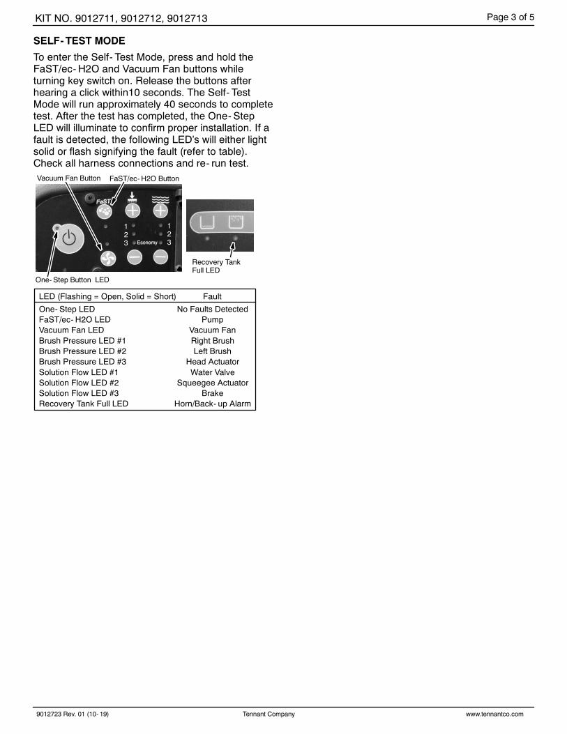
SELF- TEST MODE
To enter the Self- Test Mode, press and hold theFaST/ec- H2O and Vacuum Fan buttons whileturning key switch on. Release the buttons afterhearing a click within10 seconds. The Self- TestMode will run approximately 40 seconds to completetest. After the test has completed, the One- StepLED will illuminate to confirm proper installation. If afault is detected, the following LED’s will either lightsolid or flash signifying the fault (refer to table).Check all harness connections and re- run test.
FaST/ec- H2O ButtonVacuum Fan Button
One- Step Button LED
Recovery TankFull LED
123
123
LED (Flashing = Open, Solid = Short) Fault
One- Step LED No Faults DetectedFaST/ec- H2O LED PumpVacuum Fan LED Vacuum FanBrush Pressure LED #1 Right BrushBrush Pressure LED #2 Left BrushBrush Pressure LED #3 Head ActuatorSolution Flow LED #1 Water ValveSolution Flow LED #2 Squeegee ActuatorSolution Flow LED #3 BrakeRecovery Tank Full LED Horn/Back- up Alarm

Page 4 of 5KIT NO. 9012711, 9012712, 9012713
9012723 Rev. 01 (10- 19) Tennant Company www.tennantco.com
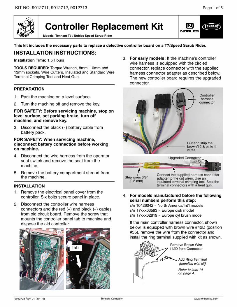
Controller Replacement Kit Contents [T7/Speed Scrub Rider]
7
8
23
1
7
9
9
4
4
4
4
5
6
5
5
5
56
5
12
10
11
13
14
For models manufactured beforefollowing serial numbers:sn 10426042 - N. America/Int’l modelssn T7xxx03593 - Europe disk modelsn T7xxx02819 - Europe cyl brush model
Brown Wire #42D
Red (+)Cable
Black (- )Cable
Main Connector
ExistingMountingScrew
15
Page 5 of 5KIT NO. 9012711, 9012712, 9012713
9012723 Rev. 01 (10- 19) Tennant Company www.tennantco.com
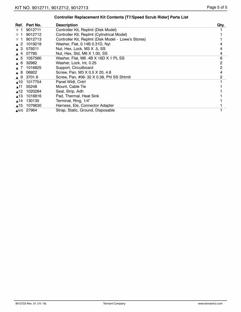
Controller Replacement Kit Contents [T7/Speed Scrub Rider] Parts List
Ref. Part No. Description Qty.o 1 9012711 ) Controller Kit, Replmt (Disk Model) 1o 1 9012712 ) Controller Kit, Replmt (Cylindrical Model) 1o 1 9012713 ) Controller Kit, Replmt (Disk Model - Lowe’s Stores) 1Y 2 1019218 Washer, Flat, 0.14B 0.31D, Nyl 4Y 3 579211 Nut, Hex, Lock, M3 X .5, SS 4Y 4 07785 Nut, Hex, Std, M6 X 1.00, SS 4Y 5 1057560 ) Washer, Flat, M6 .4B X 16D X 1 PL SS 6Y 6 32982 Washer, Lock, Int, 0.25 2Y 7 1016825 Support, Circuitboard 2Y 8 06922 Screw, Pan, M3 X 0.5 X 20, 4.8 4Y 9 3701.6 Screw, Pan, #06- 32 X 0.38, Phl SS Shtmtl 2Y10 1017754 ) Panel Wldt, Cntrl 1Y11 55248 Mount, Cable Tie 1Y12 1020284 Seal, Strip, Adh 1Y13 1016816 Pad, Thermal, Heat Sink 1Y14 130135 Terminal, Ring, 1/4” 1Y15 1076630 Harness, Ele, Connector Adapter 1YN/S 27964 Strap, Static, Ground, Disposable 1