Embed Size (px)
Citation preview

GMPP Supermatic Transmission Controller Kit Table Of Contents
Part One - Installation Instruction Contents ................................................................................ 2 1.0 Introduction .............................................................................................................................................. 2
1.1 Overview ............................................................................................................................................ 3 2.0 Wiring Harness Guidelines ..................................................................................................................... 3
2.1 Harness Connector Faces ............................................................................................................... 3 2.1.1 GM Harness Connectors .............................................................................................................. 3
2.2 Connections ...................................................................................................................................... 5 2.2.1 Main Transmission Connector - C1.............................................................................................. 5 2.2.2 GM Throttle Position Sensor (TPS) - C2 ...................................................................................... 7 2.2.3 TransComp Connection - C3 ....................................................................................................... 7 2.2.4 GM Distributor Connection - C4 ................................................................................................... 7 2.2.5 GM Input Speed Sensor - C5 ....................................................................................................... 8 2.2.6 GM Economy/Performance Connection - C6 ............................................................................... 7 2.2.7 Output Speed Sensor - C7 ........................................................................................................... 7 2.2.8 Manual Shift Connection (Optional) - C11 ................................................................................... 7 2.2.9 TCU Connection - C12 ................................................................................................................. 7 2.2.10 SCU Connection - C13 ............................................................................................................... 7 2.2.11 Voltage Supply/Ground .............................................................................................................. 7 2.2.12 Neutral Safety Switch ................................................................................................................. 7 2.2.13 GM Torque Converter Lock-up Release Switch ........................................................................ 7 2.2.14 Dyno Mode Connector…………………………………………………………………12
3.0 Glossary .................................................................................................................................................... 8 4.0 Troubleshooting ....................................................................................................................................... 8
4.1 Troubleshooting 4L60E/4L65E Solenoids ...................................................................................... 8 4.2 Troubleshooting 4L80E/4L85E Solenoids ...................................................................................... 9
5.0 Retrofit Tips .................................................................................................. Error! Bookmark not defined. 5.1 GM Transmission Retrofit ............................................................................................................... 9
Part Two - T-Com™ WP User Guide ........................................................................................... 11 1.0 Introduction ............................................................................................................................................ 11
1.1 Software License Agreement .............................................................. Error! Bookmark not defined. 1.2 System Overview ............................................................................................................................ 11 1.3 System Requirements .................................................................................................................... 11
2.0 Installation .............................................................................................................................................. 11 2.1 Automatic Installation .................................................................................................................... 11 2.2 Executing the Software .................................................................................................................. 11 2.3 Special Notes .................................................................................................................................. 11 2.4 TCU Initial Calibration Wizard ....................................................................................................... 15 2.5 Loading and Saving Calibration Files ........................................................................................... 18
3.0 Online/Offline Status .............................................................................................................................. 13 4.0 Using T-Com™ WP ................................................................................................................................ 14
4.1 Navigating with Keystrokes ........................................................................................................... 14 4.1.1 General ....................................................................................................................................... 14 4.1.2 'Hot Keys' ................................................................................................................................... 14 4.1.3 In a Menu ................................................................................................................................... 15 4.1.4 In the Data Record Screen ......................................................................................................... 15
4.2 Navigating with the Mouse………………………………………………………………….26 4.2.1 General ....................................................................................................................................... 15 4.2.2 In a 2D Table .............................................................................................................................. 15
5.0 Main Menu ............................................................................................................................................... 15 5.1 File Menu ......................................................................................................................................... 16
5.1.1 New Calibration File ................................................................................................................... 16

5.1.2 Open Calibration File ................................................................................................................. 16 5.1.3 Save Calibration File .................................................................................................................. 16 5.1.4 Save Calibration File As ............................................................................................................. 16
5.1.5 Print…………………………………………………………………………………………27 5.1.6 Calculator…………………………………………………………………………………..27 5.1.7 Exit………………………………………………………………………………………….27
5.2 Edit Menu ......................................................................................................................................... 16 5.2.1 Cut .............................................................................................................................................. 16
5.2.2 Copy………………………………………………………………………………………...28 5.2.3 Paste………………………………………………………………………………………..28 5.2.4 Undo………………………………………………………………………………………..28 5.2.5 Redo………………………………………………………………………………………..28
5.3 Calibration/Tuning .......................................................................................................................... 17 5.3.1 Shift Schedule A ......................................................................................................................... 17
5.3.1.1 Load vs Line Pressure……………………………………………………………...28 5.3.1.2 Load vs Accumulator %......................................................................................28 5.3.1.3 Part Throttle Upshift/Downshift Table……………………………………………29 5.3.1.3.1 Upshift Table………..…………………………………………………………...29 5.3.1.3.2 Downshift Table………………………………………………………………….29 5.3.1.4 TCC Lock/Unlock Table…………………………………………………………….29 5.3.1.5 TCC Lockup Parameters…………………………………………………………...29 5.3.1.6 TCC Pressure Control………………………………………………………………30 5.3.1.7 Temp vs Line Pressure Trim……………………………………………………….30 5.3.1.8 WOT Settings………………………………………………………………………..30
5.3.2 Shift Schedule B ......................................................................................................................... 31 5.3.3 Copy Calibration ....................................................................................................................... 181 5.3.4 Dyno Mode ................................................................................................................................. 19
5.4 TCU Setup ........................................................................................................................................ 33 5.4.1 Sensor Configuration ................................................................................................................. 33 5.4.1.1 Throttle Position .................................................................................................................... 33
5.4.1.2 Manifold Pressure……………………………………………………………………..34 5.4.1.3 Engine RPM……………………………………………………………………………34 5.4.1.4 Vehicle Speed………………………………………………………………………….34
5.4.2 Breakpoints and Configuration ................................................................................................... 21 5.4.3 Mode Input Setup ....................................................................................................................... 23
5.5 Datalog ............................................................................................................................................. 38 5.5.1 Start Logging .......................................................................................................................... 38 5.5.2 View ........................................................................................................................................ 38
5.6 Communications ............................................................................................................................. 23 5.6.1 Go Online…………………………………………………………………………………38 5.6.2 Go Offline…………………………………………………………………………………39 5.6.3 Retrieve Calibration from TCU…………………………………………………………39 5.6.4 Send Calibration to TCU………………………………………………………………..39 5.6.5 Monitor…………………………………………………………………………………….39 5.6.6 Flash Upgrade……………………………………………………………………………40 5.6.6.1 Select Port Manually………………………………………………………………....40 5.6.6.2 Flash Upgrade TCU…………………………………………………………………..40 5.6.7 Com Port Settings………………………………………………………………………40 5.6.7.1 Auto Retrieve on Connect………………………………………………………….40 5.6.7.2 Continuously Scan for TCU………………………………………………………..40 5.6.7.3 When Software Starts………………………………………………………………40
5.7 Software Setup ............................................................................................................................. …41 5.7.1 Monitor Setup…………………………………………………………………………..41 5.7.2 Toolbar Setup………………………………………………………………………..41 5.7.3 Unit Selection…………………………………………………………………………..…41 5.7.4 Advanced………………………………………………………………………………….41

5.8 Window………………………………………………………………………………………..42 5.8.1 Cascade…………………………………………………………………………………42 5.8.2 Tile………………………………………………………………………………………..42 5.8.3 Explorer View……………………………………………………………………………42 5.8.4 Close All Windows…………………………………………………………………….42 5.9 Help…………………………………………………………………………………42 5.9.1 About………………………………………………………………………………………42 5.9.2 Press F1 in any Window for More Info………………………………………………42 5.9.3 Check for date……………………………………………………………………………42
Part One - Installation Instruction Contents 1.0 Introduction Please check your new transmission control system contents. You should have received the following items:
• Transmission Control Unit (TCU) • Complete wiring harness with labeled connectors • T-Com™ WP software • 5-ft communications cable for TCU to laptop
1.1 Overview This GM Transmission Control Unit (TCU) system is designed to be used with the following transmissions: GM 4L60E/4L65E/4L70E and GM 4L80E/4L85E.
These transmissions are fully electronic and will not shift automatically without a transmission control system connected to it. GM’s TCU, computer software and wiring harness enable the transmission to operate. The TCU is fully programmable; part throttle, Wide Open Throttle (WOT), shift firmness and speeds can be custom tailored to the application. The torque converter lock-up is also fully adjustable. All of the wiring harness wires are clearly labeled. You can refer to the wiring diagrams for more detail, but you should find that the system is set up as a 'plug-and-play' application.
2.0 Wiring Harness Guidelines The TCU itself is weatherproof so mounting it in the engine compartment is acceptable. Although there should be ample lengths of wire, it's best to lay out all the connections first to be sure everything reaches before permanently mounting the TCU. The TCU requires an active power and ground connection to operate correctly. The power connection to the TCU should be switched (only turns on when you turn the ignition key to the start/run position). If you wire the TCU to a constant power source, you risk severe damage to the TCU and your transmission. The power source should be protected with a 10amp fuse (this can vary based on the transmission application). Your switched power source should also be capable of providing at least 10 amps (or more depending on your transmission application) and should come from a clean terminal or wire. If you splice into a wire or create a switched power junction, please protect and seal the wire or joint with sealant type heat shrink or something similar to ensure reliability. Your ground connection should be wired to a clean ground terminal on the vehicle (preferably on the transmission or engine). GM Wiring Notes The supplied wiring harness has been designed to interface with the 4L60E/4L65E/4L70E/4L80E/4L85E transmission and all required sensors without any cutting/splicing required. Standard GM connectors have been utilized during harness construction to ensure compatibility with the most common sensors.

Note: Pre-1993 4L80E transmissions will need to have an updated internal harness/connector installed to be compatible with the TCU harness. Use either GM #24200161 harness or aftermarket equivalent.
2.1 Harness Connector Faces Every connector is labeled for ease of installation. Should the label become removed/lost, this section serves as a reference to identify the various connector faces on the harness. Note: Each connector has the terminal labels molded directly onto the connector body, i.e. A, B, C, etc. The picture on the left is the vehicle speed sensor. The one on the right is the case connector.
2.1.1 GM Harness Connectors
E
A BC D
L
M N P R
S
T
C1
Transmission Case Connector
Location: 4L60E/4L65E - Passenger side of case. (top)
4L80E/4L85E - Driver side of case. (side)
U

4L60E/4L65E/4L70E CAVITY FUNCTION WIRE COLOR
A SHIFT SOLENOID A (LOW) LIGHT GREEN B SHIFT SOLENOID B (LOW) YELLOW C PRESSURE CONTROL SOLENOID (HIGH) ORANGE D PRESSURE CONTROL SOLENOID (LOW) LIGHT BLUE E BOTH SHIFT SOLENOIDS, TCC SOLENOID
AND 3-2 CONTROL SOLENOID (HIGH) PINK
L TRANSMISSION FLUID TEMPERATURE (HIGH)
DARK GREEN
M TRANSMISSION FLUID TEMPERATURE (LOW)
PURPLE
N RANGE SIGNAL “A” GRAY P RANGE SIGNAL “C” RED R RANGE SIGNAL “B” DARK BLUE S 3-2 CONTROL SOLENOID (LOW) NOT
USED WHITE
T TCC SOLENOID (LOW) BLACK U TCC PWM SOLENOID (LOW) BLACK
4L80E/4L85E CAVITY FUNCTION WIRE COLOR
A 1-2 SHIFT SOLENOID “A” (LOW) LIGHT GREEN B 2-3 SHIFT SOLENOID “B” (LOW) YELLOW C FORCE MOTOR (+) ORANGE D FORCE MOTOR (-) LIGHT BLUE E 12 VOLTS +, IGNITION ON PINK L TRANSMISSION FLUID TEMPERATURE
(HIGH) DARK GREEN
M TRANSMISSION FLUID TEMPERATURE (LOW)
PURPLE
N SWA GRAY P SWB RED R SWC DARK BLUE S TCC SOLENOID (LOW) WHITE T VOID - NOT USED BLACK
C – Red
A - Black
B - White
C2
Throttle Position Sensor (TPS)

A - Red
B - White
C Bl k
C4
C3
B - Black
TransComp
A –Orange
B - Black A - Red
C5
Input Speed Sensor (TISS - 4L80E only)
Location: Driver side of case, front sensor
Tachometer Signal (RPM REF)

A - Red B - Black
C7
Output Speed Sensor (TOSS)
Location: 4L60E/4L65E 2WD - Tailhousing
4L60E/4L65E 4WD
C - Lt. Blue B - Yellow A - Red
C11
Manual Shift (Optional)
Location: Shifter
C12 TCU Main Connector Location: End of TCU

C - Black B - Yellow
2.2 Connections Each of the connectors described in the following section has a corresponding connector number assigned to it that corresponds with the connector face diagrams in the preceding section, 2.1.
2.2.1 Main Transmission Connector - C1 The main transmission connector is the round gray one on GM harnesses. It connects all of the internal transmission solenoids. Simply plug it into the connector of the transmission. Note: The connector is keyed to line up in one orientation only. On GM applications, line the arrow on the TCU harness up with the notch on the case connector.
4L60E/4L65E - connector is located on the passenger side of the case.
4L80E/4L85E - connector is located towards the rear of the driver side of the case. Note: Pre-1993 units will need to have an updated internal harness/connector installed to be compatible with the TCU harness. Use GM #24200161 harness or aftermarket equivalent.
2.2.2 GM Throttle Position Sensor (TPS) - C2 If you are installing the transmission in a vehicle that does not have a throttle position sensor (TPS), you must install one (the TCU needs to know the throttle position in order to determine proper shift
C13
SCU (Optional)
L
A - Red
ocation: Engine

points/firmness). If you are installing the 4L60E/4L65E/4L70E/4L80E/4L85E behind a fuel-injected engine, you can simply utilize the existing TPS sensor.
2.2.3 TransComp Connection - C3 This connector allows the TCU to interface with your laptop. The TransComp connector plugs into the supplied, 5-ft. communication cable.
2.2.4 GM Distributor Connection - C4 GM - The TCU also needs a connection to the factory distributor. This lets the computer know the engine RPM. The computer uses this information to control Wide Open Throttle (WOT) shift points. If you have a late model GM electronic distributor, you can splice into the vehicle tach wiring. Alternatively, you may utilize the tach output signal from an aftermarket ignition control. Connect the white wire going to Terminal A of connector C4 to the tach output.
2.2.5 Input Speed Sensor - C5 4L80E/4L85E only - This connects to the input speed sensor (TISS) on the 4L80E transmission. This sensor is located in the driver side of the case, towards the front. The 4L60E/4L65E/4L70E transmission does not use this input.
2.2.6 Cal A/Cal B Connection - C6 Optional - A neat feature of the TCU is the ability to change to a completely different calibration at the flick of a switch. This is accomplished by hooking this lead to a dash/console-mounted toggle switch. Run the other switch pole to +12V. The default position (off) will be the Cal A setting. When switched on (+12V), the TCU will change the TCU to operate from the Cal B calibration.
2.2.7 Output Speed Sensor - C7 This connects to the output speed sensor (TOSS/VSS) located in the tailhousing of the transmission. The TCU uses this input to calculate road speed. 1993-1995 4L60E, all 4L80E/4L85E. The 1996 & later 4L60E/4L65E/4L70E transmissions with removable bellhousings have the VSS sensor located on the passenger side. Note: 1993-1995 4L60E speed sensors require a different connector.
2.2.8 Manual Shift Connection (Optional) – C8 The TCU is configured such that it's possible to have fully manual upshifts and downshifts at the flick of a switch like a bump stick. This works by first activating the manual mode with one switch to Terminal C. Once activated, the transmission can be bumped up (Terminal B) or down (Terminal C) through the forward gears via an On-Off-On momentary rocker switch. The default connections are to be made as follows: • Terminal A (red wire) - momentary +12 volts for bump down • Terminal B (yellow wire) - momentary +12 volts for bump up • Terminal C (blue wire) - +12 volts to activate manual mode
Note: These can be changed to momentary grounds within the software. Caution: Be aware that serious engine damage could occur due to over-revving if downshifts are made at too high of vehicle speed. The TCU cannot override your input while in the manual mode.
2.2.9 TCU Connection – C9 Plug this into the TCU bulkhead connector on the end. Do not over tighten.
2.2.10 SCU Connection - C10 Optional: For vehicles equipped with analog (mechanical) speedometers, a speedometer control unit is available. Plug this into the SCU lead.
2.2.11 Voltage Supply/Ground The preferred method is to connect the ground wire on the wiring harness directly to the battery. This will reduce the amount of electrical noise to the TCU. The black wire with a 3/8" ring terminal is the ground.

The ground connection should be free of paint and corrosion if grounded directly to the chassis or engine block. The Pink wire labeled '+12 V Switch' is the 12-volt ignition wire. A 10-amp inline fuse should be utilized between the power source and the TCU. This wire should only be hot when the key is in the ON position.
2.2.12 Neutral Safety Switch If your present shifter does not have provisions for a Park/Neutral safety switch and Reverse light switch, you may choose to utilize the switches built onto your transmission shift lever if so equipped.
2.2.13 GM Torque Converter Lock-up Release Switch For smoother operation, it's suggested that the wire labeled brakelight be run to a factory brake pedal switch (NC) so the TCC will unlock when you apply the brakes.
2.2.14 Dyno Mode When enabled, this mode will allow you to lockup the torque converter and choose a gear for dynamometer use. Locking up the torque converter will lower parasitic loss and will increase power numbers on the dyno. Typically you will want to choose a gear that is 1:1 to use for the dyno as this gear ratio usually has the smallest amount of loss in the transmission. Both parameters are configurable. All upshifts/downshifts will occur at the value specified by 0% TPS in the upshift/downshift tables. Upshifts will occur until reaching the desired gear specified in the dyno mode form. TCC lockup will occur based on the speed set in the dyno mode form.
3.0 Glossary BOP ……... Buick, Olds, Pontiac, Cadillac DIS ……... GM Distributorless Ignition used on Buick V6 (one
coil for every two spark plugs) ECU ……... Engine Control Unit HEI ……... GM High Energy Ignition IPU ……... Inductive Pickup Ignition — Racing crank trigger
ignitions and magnetic pickup distributors NC ……... Normally Closed NO ……... Normally Open PWM ……... Pulse Width Modulated — Varying the duty cycle of
a solenoid to control the volume or pressure in a hydraulic circuit
SCU ……... Speedometer Control Unit — uses the VSS signal to drive a standard style speedometer cable.
TCC ……... Torque Converter Clutch — controls the apply and release of the torque converter lock-up
TCU ……... Transmission Control Unit TISS ……... Transmission Input Speed Sensor — magnetic
pickup monitoring the forward clutch drum on a 4L80E/4L85E
TOSS ……... Transmission Output Speed Sensor — magnetic pickup monitoring output shaft speed
TPS ……... Throttle Position Sensor — relays throttle opening/closing to ECU and/or TCU
VSS ……... Vehicle Speed Sensor WOT ……... Wide Open Throttle

4.0 Troubleshooting This section shows how to troubleshoot the transmission solenoids/internal harness connections via the TCU main connector C12. Set your multi-meter to read resistance and probe between the indicated terminals. Caution: Be careful not to damage the terminals in the connector with the multi-meter probes. A short, open or resistance reading outside of the specification indicates a problem that needs to be investigated further. Note: The letters and numbers used to identify the terminals are molded to the connector body.
4.1 Troubleshooting 4L60E/4L65E Solenoids
Main TCU Connector
Shift Solenoid A – 20-30 Ohms at 70 degs F. Check across pins 1 and 59. Shift Solenoid B – 20-30 Ohms at 70 degs F. Check across pins 1 and 53. Pressure Control Solenoid – 3.5-8.0 Ohms at 70 degs F. Check across pins 37 and 60. TCC Solenoid (1993-1994 On/Off) Note – Solenoid is polarity specific. Put positive test lead on pin 1. 20-30 Ohms at 70 degs F. Check across pins 1 and 36. TCC Solenoid (1995 –Later PWM) – 10-15 Ohms at 70 degs F. Check across pins 1 and 36.

4.2 Troubleshooting 4L80E/4L85E Solenoids
Main TCU Connector
Shift Solenoid A – 20-30 Ohms at 70 degs F. Check across pins 1 and 59. Shift Solenoid B – 20-30 Ohms at 70 degs F. Check across pins 1 and 53. Pressure Control Solenoid – 3.5-8.0 Ohms at 70 degs F. Check across pins 37 and 60. TCC Solenoid (1995 –Later PWM) – 10-15 Ohms at 70 degs F. Check across pins 37 and 60.
Retrofit Tips 5.1 GM Transmission Retrofit The mechanical portion of this transmission swap is similar to swapping a 700R4 into an older model vehicle that was originally equipped with a Powerglide, TH350 or TH400 transmission. Depending on the application, the driveshaft may need to be lengthened or shortened. The crossmember may need to be moved and the transmission mount, bellhousing and shift linkage may need to be modified. The starter may need to be replaced as well. If you are installing a high performance aftermarket converter, you may even need to drill the flexplate holes oversize in order to accommodate larger-than-factory bolts. Be sure to check this before attempting the swap. (It's a hassle to have to remove the transmission from the car simply because the converter bolts would not go through the flexplate!) Use the dimensions listed below to determine the proper amount to move your crossmember and the amount to have the driveshaft shortened or lengthened
Transmission Overall Length
Distance to Crossmember Mount
Bellhousing Bolt Pattern
4L60E (1993-1996) 4L60E/4L65E (1996-later w/ removable bellhousing, non-LS1) 4L60E/4L65E (1998-later w/ LS1)
30 ¾" 30 ¾"
22 ½" Chevy Chevy
23 3/16" 31 5/32" 23 19/32" Chevy
4L80E/4L85E (Std. 32 11/16" 30 3/8" Chevy

2WD) 4L80E/4L85E (HD 2WD) 4L80E/4L85E (HD long)
31 15/16" 33"
30 3/8" 30 3/8"
Chevy Chevy
700R4/4L60 30 ¾" 22 ½" Chevy 2004R 27 11/16" 27" Chevy, BOP, Fit-all* Powerglide 27 11/16" 20 9/16" Chevy, BOP TH350 (6" tailshaft) TH350 (9" tailshaft) TH350 (12" tailshaft)
27 11/16" 30 11/16" 33 27/32"
20 3/8" 20 3/8" 20 3/8"
Chevy, BOP, Fit-all* Chevy, BOP, Fit-all* Chevy, BOP, Fit-all*
TH400 (C tailshaft) TH400 (D tailshaft) TH400 (13" tailshaft)
28 3/8" 33 27/32" 37 7/8"
26 15/16" 27 15/16" 27 21/32"
Chevy, BOP Chevy, BOP Chevy, BOP
* Fit-all refers to a bellhousing configured to accept either a Chevy or BOP engine. Additional 4L60E/4L65E/4L70E notes: Header/Exhaust Clearance - There are several different bellhousing configurations for the 4L60E/4L65E/4L70E transmission. The earlier models (1993-1996) have an integral bellhousing, identical to the 700R4. In some cases, the dust cover mounting ears will have to be cut off to accommodate header collectors. This can easily be accomplished with a hacksaw. The later models (1996-later) have a fully circumferential, bolt-on bellhousing. It is important to use the correct bellhousing for your application. The LS1-style 4L60E/4L65E transmissions have a unique bellhousing and input shaft. These types are not direct replacements for the non-LS1 applications. Some headers will interfere with the starter hump on the bolt-on bellhousings. It may be necessary to either dimple the header or cut off the starter hump. Starter Clearance - The bellhousing may require modifications if you intend to use a stock starter. Shift Lever - Many 1996-later, two-piece case transmissions (primarily trucks) have a shift lever that is about 1" longer than the early-style found on 700R4, TH350 & TH400. Cooler Lines - Your existing lines may have to be bent to connect to a 1996-later, two-piece case transmission. These units have fittings that are parallel to the ground instead of being angled down. You may also need to change the case fittings as many 1996 & later transmissions are equipped with the factory quick-connect style. Caution: Do not use Teflon® tape if replacing cooler fittings. It can cause the case to crack due to over tightening.
Part Two - Software User Guide 1.0 Introduction Congratulations! You have just purchased the finest aftermarket performance transmission control system available for the GM 4L60E/4L65E/4L70E, 4L80E/4L85E electronic transmissions. This control unit and programming software is designed to work with either unit. This reference manual provides you with a step-by-step guide to a PC-based control system for our Transmission Control Unit. This software allows you, through your PC, to take precise control and alter the feel of a gearshift, the timing of the gearshift and the application of the lock-up in the torque converter. The software also allows you to have the transmission shift at wide open throttle (WOT) solely as a function of engine rpm, while it continues to follow shift curves based on road speed and throttle position during part throttle driving.
1.2 System Overview The software is designed to allow maximum tuning for the performance enthusiast. The system comes pre-loaded with a transmission calibration that works well in many performance applications. There are only five fields in the Initial Setup Wizard that MUST be entered for the system to function in its pre-programmed calibration. In order to get the system up and running you simply enter (1) rear tire diameter, (2) rear gear ratio, (3) number of engine cylinders, (4) Max TPS for an idle, and (5) Min TPS for WOT. Since different users can have wide-ranging expectations of how hard and when they want the transmission to shift, our easy edit features allow for 'customizing' the characteristics to meet those expectations. CAUTION: Setting duty cycles to minimum line pressures on the force motor tables can result in slipping clutches. Changes in the line pressure duty cycle should be made in small increments.
1.3 System Requirements PC: 80386 or higher CPU Operating System: Microsoft® Windows 95/98/NT/ME/2000/XP Graphics: VGA RAM: 2MB minimum Hard Disk: 1 MB minimum RS-232: A free COM port (#1, 2, 3 or 4 without conflicting interrupts) is required. Use of a USB to RS-232 router is required in the event your PC is only equipped with a USB port.
2.0 Installation 2.1 Automatic Installation Installation from a DOS prompt • Insert the supplied software disk in your disk drive. • At the DOS command prompt, type letter of your computer's floppy drive, followed by: \install (for
example, a:\install). Note: If using DOS 6.0 or earlier, use 'a\install2'. Follow the instructions that appear on the screen to complete the installation. Installation from Windows • Insert the supplied software disk in your disk drive.
Option One • Select Start, Run. • At the command line box,
type the letter of your
Option Two • Open Windows Explorer. • Open the contents of your
floppy disk drive.
computer's floppy drive, followed by: \install (for example, a:\install).
• Double click install. • Follow the instructions that
appear on the screen to complete the installation. • Follow the instructions that
appear on the screen to complete the installation.
2.2 Executing the Software To execute the program once it's installed, click on the shortcut. A shortcut is installed in the Start Menu Programs folder.
2.3 Special Notes If the TCU is not connected and powered (key off) when the software is executed for the first time, the software will be in an 'Offline' mode. If the software is executed after the TCU is powered up (key on) and connected (by the communication cable), communication will be attempted. You can also press the CTRL G keys to cause the software to attempt communication with the TCU.
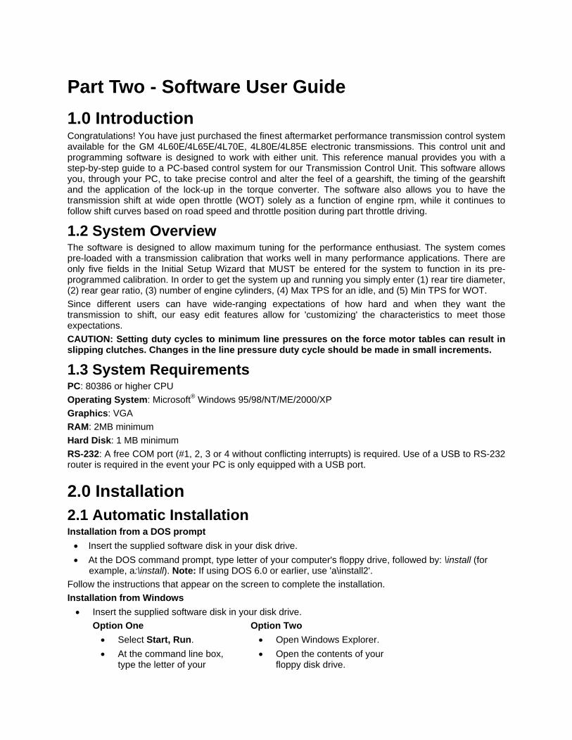
2.4 TCU Initial Calibration Wizard A new calibration file can be easily built for your particular application using the TCU Initial Setup Wizard. After installing the software, simply click on the software icon to boot the software. In the offline mode, you’ll see the following options.
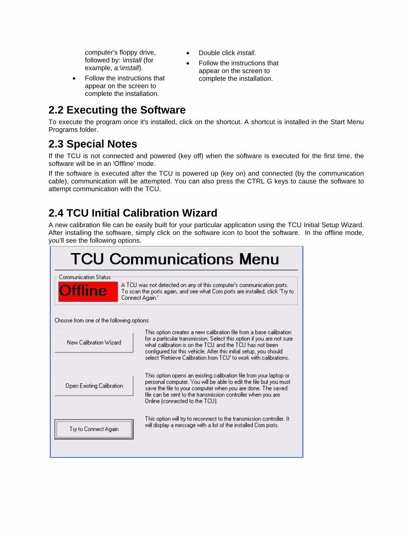
If you are starting the software for the first time, then you will want to click the New Calibration Wizard option. This will allow you to build a calibration file for your application. To build a file, choose the Transmission Type that you are running. There is no room for error on this selection. Serious damage can occur if you choose the wrong Transmission Type. Next, select the Base Calibration that best fits your application. Don’t worry if there isn’t an exact match for your application. The calibration can be fine-tuned later for your specific needs.
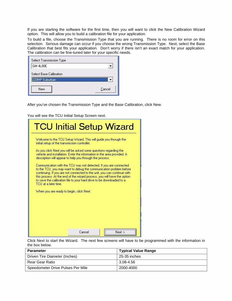
After you’ve chosen the Transmission Type and the Base Calibration, click New. You will see the TCU Initial Setup Screen next.
Click Next to start the Wizard. The next few screens will have to be programmed with the information in the box below. Parameter Typical Value Range Driven Tire Diameter (Inches) 25-35 inches Rear Gear Ratio 3.08-4.56 Speedometer Drive Pulses Per Mile 2000-4000

Number of Engine Cylinders 6-8 Type of Tachometer Standard Tach TPS Closed Throttle Voltage .40-.50 Volts TPS WOT (Wide Open Throttle) Voltage 4.4-4.6 Volts Percentage TPS for WOT 90% The next screen will be the Driven Tire Diameter screen. Simply type your tire diameter (height) into the box. If you are unsure about your tire diameter, you can use the Tire Size calculator to type in your Metric tire size and the height will be estimated for you. The next few screens are self explanatory. Simply follow the directions to program the rear gear ratio, the speedometer drive pulses per mile (only if you are using a digital speedometer), the number of engine cylinders, the type of tachometer that you are using, the TPS fully closed voltage (If you are not sure and don’t have a voltmeter, you can connect to the TCU and read the voltage via the laptop.), the TPS WOT (Wide Open Throttle) voltage, the percentage TPS for WOT, then Save your calibration. When you are in offline mode, once the file is loaded, you may make any changes you wish and save the changes to disk. Once the changes have been made, the file can be programmed into the TCU when you are in online mode. When you select a file to load in online mode, you should see a progress bar at the bottom of the screen. When the bar fills up, the new calibration file has been loaded into the TCU. The information you are viewing in the tables in online mode is what is actually programmed into the TCU. Any changes you make to any tables or fields are immediately programmed into the TCU. To save a file:
• From the pull down menu, select File/Read All Tables. • Enter a name to save the file under and press enter. The calibration file name you select will
automatically be given a .TCU file extension.
2.5 Loading and Saving Calibration Files Calibration files can be loaded or saved in one of two ways. In offline mode, a calibration file can be loaded into your PC's memory so that you can make changes offline and save them to disk. In online mode, you will be sending calibration information directly to the TCU. To load a file:
• From the pull down menu, select File, then Open Calibration File. • Select a calibration file to load. You may either double click the file or click the file once to
highlight it and then click Open. When you are in offline mode, once the file is loaded, you may make any changes you wish and save the changes to disk. Once the changes have been made, the file can be programmed into the TCU when you are in online mode. When you select a file to load in online mode, you should see a new option menu on the screen.
Now the new calibration file has been loaded into the TCU. The information you are viewing in the tables in online mode is what is actually programmed into the TCU. Any changes you make to any tables or fields are immediately programmed into the TCU. To save a file:
• From the pull down menu, select File, then Save Calibration File.

• Enter a name to save the file under and press enter. The calibration file name you select will automatically be given a .TCU file extension.
3.0 Online/Offline Status At the bottom of your screen, you’ll see the online/offline status. When no TCU is connected or there is a communication error, the display will appear as follows:
If you are in online mode (meaning that you are connected to the TCU), you will see an indication that you are in online mode.
4.0 Using the TCU Software 4.1 Navigating with Keystrokes Although a mouse should be used with the software, the following section will demonstrate how to use the keyboard for navigation and editing. 4.1.1 General All menus can be navigated with the arrow keys, the Tab key, the ALT key and the Enter key. The ESC key will generally back out from any menu. A menu may be selected by simultaneously pressing the ALT key and the first, underlined letter of the desired menu. For example, to select the File menu, press ALT and F. The arrow keys may then be utilized to make a selection or change menus.
4.1.2 'Hot Keys' Pressing a 'Hot Key' will abort the current process and immediately execute the associated function.
Software Hotkey List Key Function
Active from all menus F1 Help for current window Ctrl_G Go Online Ctrl_H Go Offline Ctrl_M Monitor Ctrl_K Monitor Setup Ctrl_N Create new calibration File Ctrl_O Open new calibration File Ctrl_S Save calibration File Ctrl_A Save calibration File as Ctrl_X Cut Ctrl_C Copy Ctrl_V Paste Ctrl_Y Redo Ctrl_Z Undo Ctrl_R Retrieve calibration from Unit Ctrl_W Watch channel Ctrl_F7 Cascade Windows

Ctrl_F8 Tile Windows Ctrl_E Explorer View
Active only from tables/charts Ctrl_L Linearize selected data Ctrl_P Add a specified percentage to selected data Ctrl_J Set selection to Ctrl_+ Add specified value to selected data Ctrl_- Subtract specified value to selected data Ctrl_i Increase/Decrease selection
Active only from datalog viewer software Right arrow Move right by one datapoint Left arrow Move left by one datapoint Up arrow Move right 10 datapoints Down arrow Move left 10 datapoints Page up Move right one page of datapoints Page down Move left one page of datapoints
4.1.3 In a Menu
With a keyboard, use the arrow keys to highlight the desired selection from the menu. Use the « key to select it.
4.1.4 In the Data Record Screen
←↑→↓ Moves the edit cursor through the graph using the left and right arrow keys.
• As the cursor is moved through the data, the dashboard in the lower portion of the window will display sensor data from the log.
• If the [Ctrl] key is pressed while moving through the data, larger steps will be made.
If the [Shift] key is pressed while moving through the data, a second cursor will appear and the sensor values in the dashboard will display the average data for the time between the cursors.
4.2 Navigating with the Mouse 4.2.1 General All menus are navigable via a mouse just as any standard Windows-style interface.
4.2.2 In a 2D Table The cursor location along a given curve can be selected by simply clicking the mouse in the desired location on the graph. (In the case of multiple parameters on the same graph, the TAB key is required to toggle between the various parameters. See Part Two-4.1.4) The value of any single point along the X-axis can be changed by simply holding the left mouse key (the cursor will appear as a small hand) and dragging the point to the desired value.

5.0 Main Menu Once a Calibration File is loaded into the software, there are nine drop down menus at the top of the T-Com™ WP interface.
5.1 File Menu Provides access to save or load files.
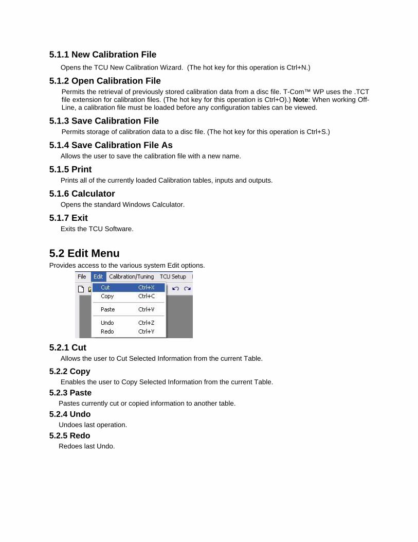
5.1.1 New Calibration File Opens the TCU New Calibration Wizard. (The hot key for this operation is Ctrl+N.)
5.1.2 Open Calibration File Permits the retrieval of previously stored calibration data from a disc file. T-Com™ WP uses the .TCT file extension for calibration files. (The hot key for this operation is Ctrl+O).) Note: When working Off-Line, a calibration file must be loaded before any configuration tables can be viewed.
5.1.3 Save Calibration File Permits storage of calibration data to a disc file. (The hot key for this operation is Ctrl+S.)
5.1.4 Save Calibration File As Allows the user to save the calibration file with a new name.
5.1.5 Print Prints all of the currently loaded Calibration tables, inputs and outputs.
5.1.6 Calculator Opens the standard Windows Calculator.
5.1.7 Exit Exits the TCU Software.
5.2 Edit Menu Provides access to the various system Edit options.
5.2.1 Cut Allows the user to Cut Selected Information from the current Table.
5.2.2 Copy Enables the user to Copy Selected Information from the current Table. 5.2.3 Paste Pastes currently cut or copied information to another table. 5.2.4 Undo Undoes last operation. 5.2.5 Redo Redoes last Undo.
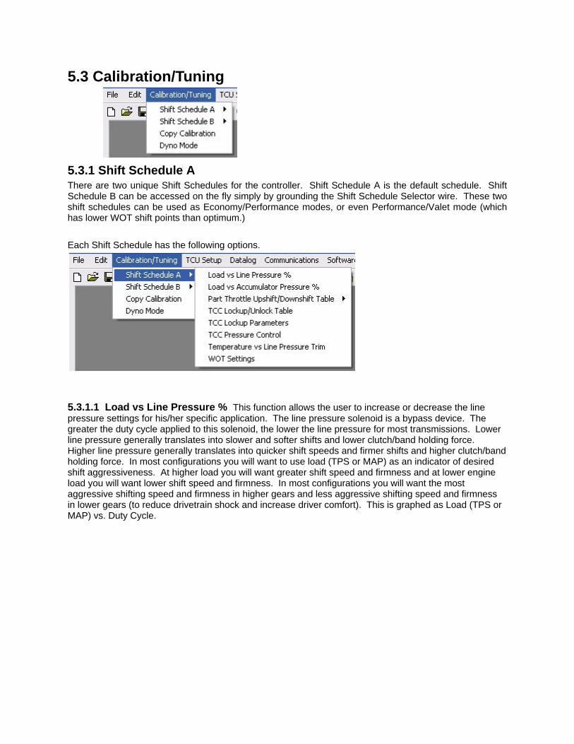
5.3 Calibration/Tuning
5.3.1 Shift Schedule A There are two unique Shift Schedules for the controller. Shift Schedule A is the default schedule. Shift Schedule B can be accessed on the fly simply by grounding the Shift Schedule Selector wire. These two shift schedules can be used as Economy/Performance modes, or even Performance/Valet mode (which has lower WOT shift points than optimum.) Each Shift Schedule has the following options.
5.3.1.1 Load vs Line Pressure % This function allows the user to increase or decrease the line pressure settings for his/her specific application. The line pressure solenoid is a bypass device. The greater the duty cycle applied to this solenoid, the lower the line pressure for most transmissions. Lower line pressure generally translates into slower and softer shifts and lower clutch/band holding force. Higher line pressure generally translates into quicker shift speeds and firmer shifts and higher clutch/band holding force. In most configurations you will want to use load (TPS or MAP) as an indicator of desired shift aggressiveness. At higher load you will want greater shift speed and firmness and at lower engine load you will want lower shift speed and firmness. In most configurations you will want the most aggressive shifting speed and firmness in higher gears and less aggressive shifting speed and firmness in lower gears (to reduce drivetrain shock and increase driver comfort). This is graphed as Load (TPS or MAP) vs. Duty Cycle.

5.3.1.2 Load vs Accumulator % Load vs. Accumulator Pressure. Many modern transmissions do not use an electronic accumulator and this form can be skipped unless your transmission uses an electronic accumulator. Typically accumulator pressure is a function of line pressure but offers additional control over shift speed and firmness. The accumulator can be thought of as a type of fluid damper. Without accumulators, shifting would feel much like “dropping” the clutch in a manual transmission. Many electronic transmissions do not offer electronic control of the accumulators. The greater the duty cycle applied to this solenoid, the lower accumulator pressure for most transmissions. Less accumulator pressure generally translates into quicker shift speeds and firmer shifts. In most configurations you will also want to use load (TPS or MAP) as an indicator of desired shift speed and firmness. At higher load you will want greater shift aggressiveness and at lower load you will want less shift aggressiveness. In most configurations you will want the most aggressive shifting speed and firmness in higher gears and less aggressive shifting speed and firmness in lower gears (to reduce drivetrain shock and increase driver comfort). This is graphed as Load (TPS or MAP) vs. Duty Cycle.
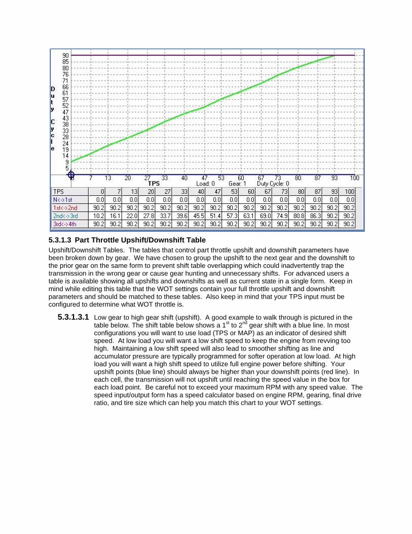
5.3.1.3 Part Throttle Upshift/Downshift Table Upshift/Downshift Tables. The tables that control part throttle upshift and downshift parameters have been broken down by gear. We have chosen to group the upshift to the next gear and the downshift to the prior gear on the same form to prevent shift table overlapping which could inadvertently trap the transmission in the wrong gear or cause gear hunting and unnecessary shifts. For advanced users a table is available showing all upshifts and downshifts as well as current state in a single form. Keep in mind while editing this table that the WOT settings contain your full throttle upshift and downshift parameters and should be matched to these tables. Also keep in mind that your TPS input must be configured to determine what WOT throttle is.
5.3.1.3.1 Low gear to high gear shift (upshift). A good example to walk through is pictured in the table below. The shift table below shows a 1st to 2nd gear shift with a blue line. In most configurations you will want to use load (TPS or MAP) as an indicator of desired shift speed. At low load you will want a low shift speed to keep the engine from revving too high. Maintaining a low shift speed will also lead to smoother shifting as line and accumulator pressure are typically programmed for softer operation at low load. At high load you will want a high shift speed to utilize full engine power before shifting. Your upshift points (blue line) should always be higher than your downshift points (red line). In each cell, the transmission will not upshift until reaching the speed value in the box for each load point. Be careful not to exceed your maximum RPM with any speed value. The speed input/output form has a speed calculator based on engine RPM, gearing, final drive ratio, and tire size which can help you match this chart to your WOT settings.

5.3.2 High gear to low gear shift (downshift). The table above also provides a good example of a 2nd to 1st gearshift. Similar methodology applies to the downshift as did for the upshift in this form. In each cell, the transmission will not downshift until reaching the speed value in the box for each load value. Be careful not to exceed your maximum RPM with any speed value. The speed input/output form has a speed calculator based on engine RPM, gearing, final drive ratio, and tire size which can help you match this chart to your WOT settings. Always keep adequate room between the upshift table and downshift table. If you do not, your transmission may hunt for gears and shift too often or in inappropriate situations.
5.3.2.3 TCC Lock/Unlock Table This table allows the user to define at what speed and load the torque converter will lock or unlock. One trick some users choose is to raise the lockup MPH at zero throttle. This is only useful when you need quick acceleration from a closed throttle condition. An example follows; if you are towing and coming down a hill, you may be at zero throttle. When you start going up the next hill, setting your lockup this way will keep the converter from locking up thereby providing quicker throttle response. An example graph can be seen in the second figure below. Many applications will want to use a normal TCC lockup curve as found in OEM applications. An example of a normal TCC lockup curve can be seen in first figure below. If TCC lockup per gear has been selected, the TCC lockup and unlock curves will be in the upshift/downshift tables and the TCC Lockup/Unlock table will disappear.

5.3.2.4 TCC Lockup Parameters The default values are shown. Enter the first gear to begin locking up the torque converter clutch (TCC) in (some transmissions will not allow lockup in some gears, usually 1st gear). Preventing lockup when the engine and transmission is cold helps to warm your engine and transmission more rapidly in cold conditions. At high fluid temps the torque converter can be locked to prevent the thermal breakdown of your transmission fluid, seals and mechanical failure. TCC lockup may be selected per gear or for all gears (normal). TCC lockup per gear provides a different TCC lockup and unlock curve for each gear. Normal TCC lockup provides a single TCC lockup and unlock curve that is not gear related. Most users should select normal TCC lockup. TCC lockup per gear should only be used by advanced users and for

installations requiring this complexity. The TCC can be unlocked during upshifts and downshifts to provide smoother shifting and alleviate drivetrain harshness.
5.3.2.5 TCC Pressure Control PWM TCC Pressure Control. Torque converter lockup rate control is provided to allow for smooth lockup and unlocking of the torque converter. This sometimes needs to be changed if you have a high stall torque converter that features a small diameter lockup clutch. In this case, you will want to increase the Lockup Ending Duty Cycle to a higher %. You may also want to Increase the Lockup Rate (% per second) to some higher number as well. Be sure to set the lockup ending duty cycle at a value that is high enough to prevent TCC slippage when the converter is locked!
5.3.2.6 Temperature vs Line Pressure Trim A Temperature vs. line pressure trim allows the user to raise or lower the line pressure in extreme climates. This trim can be based on the transmission fluid temperature sensor. The behavior of line pressure with respect to temperature should be based on the transmission fluid temperature.

5.3.2.7 WOT Settings These parameters determine where your vehicle will upshift and downshift when the Throttle Position Sensor (TPS) reaches a value high enough to trigger WOT mode. You can define what WOT is by changing the WOT voltage in the analog input for your TPS. To disable the WOT mode altogether, program 0% for the % of WOT throttle voltage to use WOT parameters in the TPS analog input form. This can be done in the case of no RPM input (ie. Some diesel applications.) The WOT upshift rpm values determine when your transmission will upshift with respect to engine RPM. This is programmable per gear, so the WOT upshift RPM for 1st gear controls the 1-2 upshift RPM. WOT downshifts are determined by speed and determine the minimum speed at which the next lower gear may be selected. For example if you are in 4th gear and go WOT at 95mph, you will only downshift to 3rd if you place a value greater than 95mph in the WOT downshift MPH 4th gear setting. When setting these parameters please keep your engine RPM in mind. You should never allow a WOT downshift near redline because you will be immediately upshifting or over-revving. Your WOT values should be matched to your part throttle upshift and downshift tables.
5.3.2 Shift Calibration B As mentioned before, shift calibration B can be used as a performance mode, or as a towing mode, or even valet mode. This can be programmed by the end user. If you don’t desire to use calibration B, then you can simply ignore these tables. Calibration B provides a completely different calibration which allows different accumulator pressure, line pressure, shift points, TCC lockup points, TCC pressure control, TCC lockup parameters, temperature trims, and WOT settings. To enable calibration B, a digital input must be set to trigger calibration B or test mode may be used to trigger calibration B. Some users link manual mode operation with calibration B so that when a manual mode input is triggered, a calibration B input is

also triggered. This provides different line pressure, TCC lockup and trim parameters for manual mode shifting.
5.3.3 Copy Calibration Copy Calibration. This form has been provided to speed tuning of calibration B. Choose which calibration to copy from and which to copy to. This will overwrite the previous calibration being copied to.
5.3.4 Dyno Mode Dyno mode is provided to allow use on a chassis dynamometer without any upshifts or downshifts. Once the programmed gear and speed are reached, the TCC will remain engaged until the vehicle speed becomes low enough to trigger a downshift at the 0% load/throttle value in the part throttle upshift/downshift tables. It simply requires a digital input from the user.
5.4 TCU Setup The TCU setup includes the sensor configuration that was setup by the TCU Initial Setup Wizard. If you change your TPS or decide to use a MAP sensor to measure engine load instead of a TPS, then it can be setup using this tab.
5.4.1 Sensor Configuration 5.4.1.1 Throttle Position This sensor configuration is required for all applications. This is typically input during the initial configuration, but can be done later if you so desire. The voltage is typically from .4 to .5 volts at an idle and from 4.4-4.6 volts at WOT. If you are using the TCU in an application that does not have an RPM reference, then you may change the % of TPS for WOT to 0%. This will allow you to control WOT shift points with the Part Throttle Shift tables.
5.4.1.2 Manifold Pressure You may elect to use engine manifold pressure instead of throttle position to determine engine load in certain applications. Typically turbocharged applications are better suited to using manifold pressure instead of TPS readings. Most applications will not require the use of a MAP sensor input. If you use this input, you must choose a calibration for your particular MAP sensor.

5.4.1.3 Engine RPM The Engine RPM calibration will simply require you to enter the number of cylinders as well as the type of tachometer input that you have. Some late model COP (Coil On Plug) applications require the use of less than the actual number of cylinders to be input. (ie. The LS based V8 engines will require the number of cylinders to be 4 instead of 8.) This is because of the number of pulses per engine rev that this type of engine has. Concerning the type of tach, most late model vehicles should be standard tach. If you have an older points type ignition, you should select the high voltage tach. If you have a magnetic trigger, then choose that type tach.
5.4.1.4 Vehicle Speed The next screen require you to input parameters such as tire diameter, rear gear ratio, output speed sensor Pulses Per Mile, the 4WD Low Transfer Case Ratio.
5.4.2 Breakpoints and Configuration This next screen will allow you to use the TPS or MAP to control Line Pressure, Accumulator Pressure and Torque Converter Lock Up functions. Most normally aspirated applications will use the TPS for these functions.

5.4.3 Mode Input Setup The Mode Input Setup screen will allow you to change the Function inputs for the different Modes that are featured in the TCU. You can utilize either a +12V source or a Ground source to activate these features. Most of these can be used with either momentary or toggle inputs. The reverse logic function allows you to activate the different modes when the input source is not applied.
5.5 Datalog Datalogging is one of the most powerful features offered by the TCU. It allows a user to see transmission behavior and engine behavior. The extra analog and digital inputs offered by the TCU also allows the TCU to be used as a general datalogging device for any other vehicle functions you may wish to record. To begin a datalog, do the following:
1. The TCU power must be on and the TCU must be communicating/online with your computer.
2. Go to the datalog pull down/explorer folder. Double click the Start Logging button. 3. A window will appear with the option to “Start Logging” and several Datalogging rates will
be offered. Choose your datalogging rate and click on the “Start Logging” button. When prompted, choose a file name and location for your datalog. As with calibration files you may want to choose a descriptive name including the time, date, and/or application of your datalog. Once you have chosen a name and location, click save or press enter.
4. The software and your computer will now begin datalogging. You may view the transmission behavior through the monitor screen while datalogging.
When you have completed your datalog, you may click on the “stop logging” button. This will complete your datalogging session and save your datalog file to the location you specified.

5.5.1 Start Logging Click the Start Logging Button to begin the datalog.
5.5.2 View To view a datalog, do the following: Datalogs may be viewed with the Datalog Viewer software, Microsoft Excel or any other program that can handle the tab delimited values contained in the datalog. The Datalog Viewer software offers a much stronger set of capabilities and datalogging viewing options; however we understand that many users may wish to use other tools or analysis methods which do not fall within the scope of the TCU software. The datalog files use the file extension .tlg which is associated with the Datalog Viewer Software; however this does not prevent users from opening the same file in Microsoft Excel. To use the Datalog Viewer software, go to the datalog pull down/explorer folder. Double click the view button. If you know the location of the datalog file, you may also open this file directly, which will automatically start the Datalog Viewer software. If the Datalog Viewer software is not being opened with a file, a blank screen will appear. Click the “load” button or go to File-> Open. Choose the file location and name and click open or hit enter. Initially, your datalog will appear in graph view. To begin viewing the data, click in the boxes next to the datafields you wish to see near the top of the screen. You may view this data in a tabular view by clicking the table view button on the icon menu. Several zooming options are available by right clicking your mouse button. You may zoom in by clicking on a beginning time and an ending time for your graph selection. You may also choose to view all the data, zoom to a percentage, or zoom to a particular time period. Please refer to the hotkeys list for a complete listing of key options for navigating the datalog menu. You may load another datalog or continue tuning at any time.
5.6 Communications The TCU has two modes of communication, CAN and RS-232. They have the following specifications.
Controller Area Network (CAN) • Noise tolerant, high speed communication standard typical in automotive applications

• 1Mb/s maximum transfer rate • Meets 2.0b specifications • User definable configuration and messages
RS-232
• Noise tolerant, low speed PC compatible communication standard • 38.4 Kbps maximum transfer rate • Used for datalogging & PC communication
Online Mode vs. Offline Mode When in offline mode, the software background will be gray. Offline mode simply means that the TCU is not connected and is not currently communicating with the PC. Any changes made to a calibration while in offline mode must be saved in that calibration and will not affect the TCU unless that calibration is sent to the TCU when it is connected. When in online mode, the software background will be blue. Online mode simply means that the TCU is connected and is currently communicating with the PC. Any changes made to the calibration will occur in real-time and will directly affect the programming of the TCU.
Transmission Setup Verify Communication. The TCU software will attempt to auto-detect the TCU when it is plugged into your computer. If the TCU software is unable to auto detect the presence of the TCU, you should double check that your serial port is active or your USB to serial port adapter is properly installed and functioning. Check that no other software is running and that no other programs may be using the serial port. Often customers will have PDA software, GPS software or a second session of the TCU software running which will interfere with proper TCU communication. Once your hardware has been checked, use the Communications -> Go Online command or CTRL-G to attempt to connect to the TCU again. If you are still unable to connect to the TCU, please contact our technical support.
5.6.1 Go Online If you are working in Offline Mode, simply press CTRL-G to connect and go on-line. Make sure that your ignition key is on and that you do have +12V to the TCU. 5.6.2 Go Offline If you are working in Online Mode, simply press CTRL-H to disconnect and go off-line. 5.6.3 Retrieve Calibration from TCU This feature allows you to retrieve the TCU calibration and save it to your computer or to an external disk. 5.6.4 Send Calibration to TCU

This overwrites the current TCU calibration. 5.6.5 Monitor The monitor screen offers a wealth of information regarding the current status of the engine, transmission and TCU. To get to the monitor screen, go to the communications pull down/explorer folder and select monitor. Alternatively, the hotkey CTRL-M will also work. A large screen will appear with several gauges and a full listing of TCU input/output status. The gauge units and increments may be changed with the setup button available when the monitor screen is open. 5.6.6 Flash Upgrade
Flash Upgrade Procedure The flash upgrade procedure should not be used unless well understood. The flash upgrade procedure is not intended to change a calibration file or to tune the transmission controller. The flash upgrade procedure is only used for firmware upgrades. Firmware upgrades directly modify the code in the control systems of the transmission controller. The ability to flash upgrade the firmware allows the transmission controller to be upgraded in the field so that new features can be added and possible problems can be remedied. 5.6.6.1 Select Port Manually This screen allows the user to manually choose which Com port to use for Flash upgrades only.
5.6.6.2 Flash Upgrade TCU To perform a flash upgrade, do the following:
1. The TCU power must be on and the TCU must be communicating and online with your computer.
2. To begin a flash upgrade, select Communications -> flash upgrade from the explorer menu or Communications -> flash upgrade -> flash upgrade TCU from the toolbar. Once this form opens, no other forms will be available. This is done to protect the TCU. At this form, the firmware major and minor revision will be displayed. The hardware revision will also be displayed.
3. To begin flashing the transmission controller, click the "Open Flash File to Begin" button. This will open a file selection menu. Only *.rom files can be opened and the correct file must be chosen for a proper upgrade. If you are unsure about which rom file you should use, contact technical support first. When using newer software with an older controller (or vice versa), the unit may not communicate or properly find the com port until it is flash upgraded. You may need to manually select the com port. Once the correct file has been selected, click open in the current menu.
4. A warning message will appear with a warning not to turn the power off until the upgrade is complete. Follow these instructions explicitly. Heed this warning! Click the yes button if you are prepared to flash the unit.

The initial flash upgrade screen will display a progress bar and provide some information about the flash procedure. Once complete, the last line of text will read “Flash upgrade complete!”
5. If you experience a box that appears saying “error writing to unit please check connection and try again.” You will need to turn the unit off and on again, check all your connections and start over with these directions. Your unit will not begin to function properly again until a successful flash has been completed.
5.6.7 Com Port Settings 5.6.7.1 Auto Retrieve on Connect. The software will auto-detect the presence of the transmission controller. It can automatically retrieve the configuration upon connection. 5.6.7.2 Continuously Scan for TCU You can also choose to have the software continuously scan for the TCU.
5.6.7.3 When Software Starts You have two options under this tab. The first is to autoscan at startup. This feature searches all ports. The second option is to attempt to use the last port that was used. 5.7 Software Setup 5.7.1 Monitor Setup This screen allows the user to program the monitor screen to their specific requirements. On this screen you can program the tach, vehicle speed and MAP gauges on the monitor screen.
5.7.2 Toolbar Setup

This feature allows the user to customize the toolbar and include shortcuts to many of the TCU features.
5.7.3 Unit Selection The user can choose units for temperature, MAP and vehicle speed, as well as overall Metric or Standard units.
5.7.4 Advanced This screen allows the user to change the sampling rate and screen update rate. The defaults are shown below and are good for most applications.

5.8 Window The Window Tab allows the user to choose how they view the tables within the software. You can choose between Cascade, Tile and Explorer Views. You can also click the Close All Windows option to close all of the table windows.
5.8.1 Cascade 5.8.2 Tile 5.8.3 Explorer View 5.8.4 Close All Windows 5.9 Help This tab has three different options. 5.9.1 About The about option displays the version of the software. As you can see below, this particular example shows Version 2.0.0. 5.9.2 Press F1 in any Window to get More Information If you need help on any particular table, simply press the F1 button to get assistance. The help menu will display the appropriate information for the section that you are working in. 5.9.3 Check for Update Does not work in this version of the software.