Embed Size (px)
Citation preview

Shock and Vibration 10 (2003) 81–95 81IOS Press
Control of rotary cranes using fuzzy logic
Amjed A. Al-mousaa, Ali H. Nayfehb,∗ and Pushkin KachroocaSoftware Engineer, Intel Corporation, Santa Clara, CA 95053, USAbDepartment of Engineering Science and Mechanics, MC 0219, Virginia Polytechnic Institute and State University,Blacksburg, VA 24061, USAcDepartment of Bradley Electrical and Computer Engineering, MC 0111, Virginia Polytechnic Institute and StateUniversity, Blacksburg, VA 24061, USA
Received 7 December 2001
Revised 6 August 2002
Abstract. Rotary cranes (tower cranes) are common industrial structures that are used in building construction, factories, andharbors. These cranes are usually operated manually. With the size of these cranes becoming larger and the motion expected to befaster, the process of controlling them has become difficult without using automatic control methods. In general, the movementof cranes has no prescribed path. Cranes have to be run under different operating conditions, which makes closed-loop controlattractive.In this work a fuzzy logic controller is introduced with the idea of “split-horizon”; that is, fuzzy inference engines (FIE) areused for tracking the position and others are used for damping the load oscillations. The controller consists of two independentsub-controllers: radial and rotational. Each of these controllers has two fuzzy inference engines (FIE). Computer simulationsare used to verify the performance of the controller. Three simulation cases are presented. In the first case, the crane is operatedin the gantry (radial) mode in which the trolley moves along the jib while the jib is fixed. In the second case (rotary mode), thetrolley moves along the jib and the jib rotates. In the third case, the trolley and jib are fixed while the load is given an initialdisturbance. The results from the simulations show that the fuzzy controller is capable of keeping the load-oscillation anglessmall throughout the maneuvers while completing the maneuvers in relatively reasonable times.
Nomenclature
rd(t) Radial distance desired by the operator.ra(t) Actual radial distance.Er(t) Radial distance error.r(t) Radial acceleration.γd(t) Rotational angle desired by the operator.γa(t) Actual rotational angle.Eγ(t) Rotational angle error.γ(t) Rotational acceleration.φ(t) In-plane angle.θ(t) Out-of-plane angle.P Positive.N Negative.L Large.
∗Corresponding author. Tel.: +1 540 231 5453; FAx: +1 540 2312290; E-mail: [email protected].
M Medium.S Small.
1. Introduction
The crane can be considered as one of the most im-portant tools used in industry to transfer loads and car-go from one spot to another. Usually cranes have verystrong structures in order to lift heavy payloads in facto-ries, in building construction, on ships, and in harbors.In factories, cranes speed up the production processesby moving heavy materials to and from the factory aswell as moving the products along production or as-sembly lines. In building construction, cranes facilitatethe transport of building materials to high and criticalspots. Similarly on ships and in harbors, cranes savetime and consequently money in making the process
ISSN 1070-9622/03/$8.00 2003 – IOS Press. All rights reserved

82 A.A. Al-mousa et al. / Control of rotary cranes using fuzzy logic
Base
Tower
Ref.
Load
Trolley
Jib
k
ir(t)
j
O
P
Cable L(t)
γ(t)
Fig. 1. A 3D model of a rotary crane.
Suspension Point
Vertical Line
Load Line
LoadP
Q
k
i
j
φ(t)
θ(t)
Fig. 2. Oscillation anglesφ(t) andθ(t) of the load.
of loading and unloading ships fast and efficient. Un-til recently, cranes were manually operated. But sincecranes are becoming larger and are being moved at highspeeds, their manual operation is becoming increasing-ly difficult. Consequently, methods of automating theiroperations are being sought [1].
Several researchers have investigated the control ofrotary cranes. Parker et al. [2,3] presented severalinput-shaping techniques to bring the load to rest atthe end point of a predefined motion profile. However,oscillations up to10◦ developed during maneuvers forgiven profiles using these techniques. Parker et al. [4]

A.A. Al-mousa et al. / Control of rotary cranes using fuzzy logic 83
Operator
Console
Fuzzy
Controller
System
Dynamics
Desired Position
Radial &
Rotational
Accelerations
Radial & Rotational Position,
In-Plane & Out-of-Plane Angles
Fig. 3. System block diagram with fuzzy logic controller.
FIE I
Tracking
Operator
Command FIE II
Oscillations
Damping
Feedback Signals
Rotational
Acceleration
Variable Share
Mixing Block
Fig. 4. Two FIEs are inside each FLC.
41 2 30 5-1-2-3-4-5
NM NS Z PS PM PLNL
0.5
1.0
0
Radial Distance Error (m)
Fig. 5. Fuzzification ofEr(t).
presented another controller based on filtering the in-put signal commanded by the operator. The controllerused a notch filter to eliminate the components of theslew and travel inputs that happen to be at the naturalfrequency of the payload pendulum. Even though ex-perimental results showed reduced load pendulationsthroughout the travel, a delay of up to 2.5 seconds oc-curred between the operator input and the actual inputfrom the filter to the cranes. This delay produces incon-
venience to the operator. It can also cause confusionin case of accidental inputs. Moreover, because thenotch filter is dependent on the length of the hoistingcable, the roll off factor of the filter must be computedeach time the cable length is changed. Furthermore,the input shaping and the notch filter controllers areopen-loop controllers, which make them inefficient inthe presence of external disturbances.
As an example of closed-loop controllers, Golaf-

84 A.A. Al-mousa et al. / Control of rotary cranes using fuzzy logic
0 0.2 0.4 1-0.2-0.4-0.6-0.8-1
NM NS Z PS PM PLNL
0.5
1.0
0
Derivative of Radial Distance Error (m/s)
0.60.6 0.8
Fig. 6. Fuzzification ofEr(t).
0 1 2 3 4 5-1-2-3-4-5
NM NS Z PS PM PLNL
0.5
1.0
0
Radial Acceleration (Track) ( m/s^2 )
Fig. 7. Fuzzification ofφ(t).
Table 1The radial tracking rules
Derivative of radial distance errorPL PM PS Z NS NM NL
Radial distance error PL PL PL PM PM PS PS ZPM PL PM PM PS PS Z NSPS PM PM PS PS Z NS NSZ PM PS PS Z NS NS NM
NS PS PS Z NS NS NM NMNM PS Z NS NS NM NM NLNL Z NS NS NM NM NL NL
Table 2The radial oscillations damping rules
In-plane angleφ(t)PL PM PS Z NS NM NL
Derivative P NL NM NS Z PS PM PLof in-plane Z Z Z Z Z Z Z Zangleφ(t) N NL NM NS Z PS PM PL
shani et al. [5] generated time optimal trajectories ofthe jib, the trolley, and the cable length. A bang-bangcontroller was then used to track these optimal trajecto-ries. Computer simulations showed uncontrolled loadpendulations. To attain better results, they relaxed the
constraint on time to 110% of the optimal value andobtained reduction in the payload pendulations. Evenwith this modification, significant pendulations persist-ed throughout the maneuver.
Although the following discussion is directed at oth-
A.A. Al-mousa et al. / Control of rotary cranes using fuzzy logic 85
0 1 2 3 4 5-1-2-3-4-5
NM NS Z PS PM PLNL
0.5
1.0
0
In-Plane Angle - φ (Degrees)
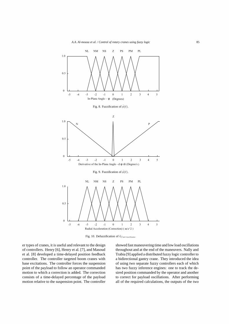
Fig. 8. Fuzzification ofφ(t).
0 1 2 3 4 5-1-2-3-4-5
Z
PN
0.5
1.0
0
Derivative of the In-Plane Angle - d φ /dt (Degree/s )
Fig. 9. Fuzzification ofφ(t).
0 1 2 3 4 5-1-2-3-4-5
NM NS Z PS PM PLNL
0.5
1.0
0
Radial Acceleration (Correction) ( m/s^2 )
Fig. 10. Defuzzification ofrCorrection.
er types of cranes, it is useful and relevant to the designof controllers. Henry [6], Henry et al. [7], and Masoudet al. [8] developed a time-delayed position feedbackcontroller. The controller targeted boom cranes withbase excitations. The controller forces the suspensionpoint of the payload to follow an operator commandedmotion to which a correction is added. The correctionconsists of a time-delayed percentage of the payloadmotion relative to the suspension point. The controller
showed fast maneuvering time and low load oscillationsthroughout and at the end of the maneuvers. Nally andTrabia [9] applied a distributed fuzzy logic controller toa bidirectional gantry crane. They introduced the ideaof using two separate fuzzy controllers each of whichhas two fuzzy inference engines: one to track the de-sired position commanded by the operator and anotherto correct for payload oscillations. After performingall of the required calculations, the outputs of the two

86 A.A. Al-mousa et al. / Control of rotary cranes using fuzzy logic
0 1 2 3 4 5-1-2-3-4-5
NM NS Z PS PM PLNL
0.5
1.0
0
Rotational Angle Error - δγ (Degrees)
Fig. 11. Fuzzification ofEγ(t).
0 5 10 15 20 25-5-10-15-20-25
NM NS Z PS PM PLNL
0.5
1.0
0
Derivative of the Rotational Angle Error - d(δγ)/ dt (Degree/s)
Fig. 12. Fuzzification ofEγ(t).
Table 3The rotational tracking rules
Derivative of rotational angle errorPL PM PS Z NS NM NL
Rotational angle error PL PL PL PM PM PS PS ZPM PL PM PM PS PS Z NSPS PM PM PS PS Z NS NSZ PM PS PS Z NS NS NM
NS PS PS Z NS NS NM NMNM PS Z NS NS NM NM NLNL Z NS NS NM NM NL NL
engines are combined to obtain the final control sig-nal. The controller was used to drive the crane along apath generated by an input-shaping strategy. They ob-tained good results for damping the oscillations and atthe same time reducing the payload travel time. In thispaper, we extend this work to rotary cranes in whichboth the trolley and jib are allowed to move.
2. Mathematical modeling
To derive the equations of motion, one needs to de-fine clearly the system parameters. As shown in Fig. 1,
a right-handed Cartesian coordinate systemxyz is cen-tered at a reference point that lies in the plane of thejib at the center of the crane tower, with its positivez-axis being along the tower upward axis. Thex- andy-axes are in the plane of the jib, with thex-axis beingalong the jib. Thexyz coordinate system is attachedto the moving jib. The jib rotates and traces an angleγ(t). The trolley moves on the jib with its positionr(t)being the distance measured from the reference pointof the xyz coordinate system to the suspension pointof the payload cable on the trolley. The angleγ(t) andthe radial distancer(t) are the inputs to the system.

A.A. Al-mousa et al. / Control of rotary cranes using fuzzy logic 87
0 1 2 3 4 5-1-2-3-4-5
NM NS Z PS PM PLNL
0.5
1.0
0
Rotational Angular Acceleration (Track) (rad /s^2 )
Fig. 13. Defuzzification ofγTrack.
0 1 2 3 4 5-1-2-3-4-5
NM NS Z PS PM PLNL
0.5
1.0
0
Out-of-Plane Angle - θ (Degrees)
Fig. 14. Fuzzification ofθ(t).
They are used to control the system behavior. We mod-el the load as a point mass. The interaction betweenthe load and crane dynamics is neglected because themass of the crane is very large compared to that ofthe load. Moreover, the damping in the system is verysmall and hence we neglect it in the model. Includingthis damping would slightly improve the performanceof the controller.
We start by defining the velocity and acceleration ofthe trolley in the jib-fixed coordinate system as
vx = ri and ax = ri (1)
The angular velocity and acceleration of the jib are
ω = γk and α = γk (2)
The load pendulations are characterized by the twoanglesφ andθ, as shown in Fig. 2. The angleφ isthe angle which the cable makes with thez−axis inthe xz−plane. The out-of-plane angleθ is the anglewhich the cable makes with thexz−plane. So it is clearnow that the objective of the controller is to move thepayload while keepingφ andθ as small as possible.
The first step in deriving the equation of motion usingthe Lagrangian approach is to find the positionP (t) of
the load with respect to the reference point O. In thejib-fixed coordinate system, the load position is
P (t) = [r(t) − L(t) cos θ(t) sin φ(t)] i + [L(t)
sin θ(t)]j − [L(t) cos θ(t) cosφ(t)] k(3)
To determine the kinetic energy of the load, we needto determine the velocityP (t) of the load. Since the jibis moving,
P (t) =∂P (t)
∂t+ ω(t) × P (t) (4)
The kinetic and potential energies of the load are givenby
KE =12mLoad[P (t).P (t)] (5)
PE = −mLoadgL(t) cos θ(t) cosφ(t) (6)
Finally, the Euler Lagrange equation correspondingto the LagrangianL = KE − PE are
d
dt(∂L∂xi
) − ∂L∂xi
= 0 (7)

88 A.A. Al-mousa et al. / Control of rotary cranes using fuzzy logic
0 1 2 3 4 5-1-2-3-4-5
Z
PN
0.5
1.0
0
Derivative of the Out-of-Plane Angle - d θ/dt (Degree/s )
Fig. 15. Fuzzification ofθ(t).
0 1 2 3 4 5-1-2-3-4-5
NM NS Z PS PM PLNL
0.5
1.0
0
Rotational Angular Acceleration (Correction) (rad /s^2 )
Fig. 16. Defuzzification ofγCorrection.
wherex1 = θ andx2 = φ. With the assumption thatthe cable length is constant, this yields the followingtwo nonlinear equations of motion:
θ(t) − 2γ(t) cos φ(t) cos2 θ(t)φ(t) +12
sin 2θ(t)φ2(t) − 12γ2(t) sin 2θ(t) cos2 φ(t)+
g
Lsin θ(t) cos φ(t) +
2L
r(t)γ(t) cos θ(t)− (8)
1L
r(t)γ2(t) sin φ(t) sin θ(t) +1L
r(t) sin θ(t)
sin φ(t) +1L
r(t)γ(t) cos θ(t) − γ(t) sin φ(t) = 0
cos θ(t)φ(t) + 2γ(t) cos θ(t) cosφ(t)θ(t)−2 sin θ(t)φ(t)φ(t) +
g
Lsinφ(t) + cosφ(t)γ2
(t)[r(t)L
− sin φ(t) cos θ(t)]
+ γ(t) sin θ(t) (9)
cosφ(t) − 1L
r(t) cosφ(t) = 0
3. Controller design
As shown in Fig. 3, we start with the input signalsfrom the operator. These signals represent the desiredradial positionrd(t) and rotational angleγd(t). Thesetwo signals can be read from the operator’s handle (joystick). The fuzzy controller receives four other inputsfrom the feedback loop: the actual radial distancera(t),the actual rotational angleγa(t), the in-plane angleφ(t), and the out-of-plane angleθ(t). The fuzzy log-ic controller (FLC) generates the radial and rotationalaccelerations, which are input to the system dynamicsblock. Two separate controllers are employed. One isradial, which takes care of the transverse motion of thetrolley over the jib; and the other is rotational, whichhandles the rotational motion of the jib.
Two fuzzy inference engines (FIE) are used insideeach controller, Fig. 4. The first is a tracking FIE,which has the desired and actual radial distances asinputs for the radial controller and the desired and actualrotational angles as input for the rotational controller.The second is an oscillation damping FIE, which hasthe in-plane angleφ as an input for the radial controllerand the out-of-plane angleθ as input for the rotational

A.A. Al-mousa et al. / Control of rotary cranes using fuzzy logic 89
Table 4The rotational oscillations damping rules
Out-of-plane angleθ(t)PL PM PS Z NSθ NM NL
Derivative of out-of-plane angleθ(t) P PL PM PS Z NS NM NLZ Z Z Z Z Z Z ZN PL PM PS Z NS NM NL
-0.4
-0.3
-0.2
-0.1
0
0.1
0.2
0.3
0.4
0 1 2 3 4 5 6 7 8
Time [sec]
Velo
cit
y [
m/s
] &
Accele
rati
on
[
m/s
2 ]
Acceleration
Veolcity
Fig. 17. Operator radial signal.
0 5 10 15 20 25 30 35 40- 8
- 6
- 4
- 2
0
2
4
6
8
Time [sec]
In-
pla
ne A
ngle
[D
egre
es]
Uncontrolled
Controlled
Fig. 18. In-plane angleφ(t) for the gantry case using the fuzzy controller.]Uncontrolled vs controlled in-plane oscillation angleφ(t) for thegantry case using the fuzzy controller.
controller. The outputs of the two FIEs are input toa variable-share mixing block, where the output fromthe tracking FIE is multiplied by a factorK and theoscillation damping FIE output is multiplied by1 −K. Then, the scaled outputs are added to obtain thecontroller output (acceleration).
The gainK is assigned a fixed value by trial and
error. However, it can be varied or it can be changed
by the operator according to the current conditions of
transportation. Care must be exercised in the choice of
K because some values might lead to instability. The
output of the radial controller isrReference(t), and the
output of the rotational controller isγReference(t).

90 A.A. Al-mousa et al. / Control of rotary cranes using fuzzy logic
0 5 10 15 20 25 30 35 400
0.2
0.4
0.6
0.8
1
1.2
Time [sec]
Radia
l D
ista
nce [
m]
Desired
Actual
Fig. 19. Radial distance for the gantry case using the fuzzy controller.]Desired and actual radial distances for the gantry case using the fuzzycontroller.
0 1 2 3 4 5 6 7 8
- 0.5
- 0.4
- 0.3
- 0.2
- 0.1
0
0.1
0.2
0.3
0.4
0.5
Time [sec]
Angula
r V
elo
cit
y [
rad/s
] &
Angula
r A
ccele
rati
on
[ ra
d/s
2 ]
Angular Acceleration
Angular Veolcity
Fig. 20. Operator rotational signal.
3.1. Radial (Gantry) Mode of Operation
This controller determines the radial acceleration ofthe trolley, which is fed to the system dynamics blockto find the response. The outputs of the following FIEsare mixed with a gainKRadial = 0.8.
Tracking FIE:This FIE has the actual radial distancera(t) and
the desired radial distancerd(t) and their derivativesra(t) andrd(t). Its output isrTrack. Before applyingthe fuzzy rules, we calculate two variables, the radialdistance errorEr(t) and its derivative as follows:
Er(t) = rd(t) − ra(t) and(10)
Er(t) = rd(t) − ra(t)
Then, they are fuzzified using the fuzzy sets shownin Figs. 5 and 6, and subsequently the rules in Table 1are applied in order to findrTrack. The rules in Table 1are generic fuzzy PD controller rules, which are similarto those used by Nally and Trabia [9]. As a result ofapplying the previous rules, we have a fuzzy notion ofthe output variablerTrack, which is transformed into acrisp value using the centroid method. Figure 7 showsthe fuzzy sets ofrTrack.
Oscillation Damping FIE:In this FIE, the input variables areφ(t) andφ(t). The
rules here are based on imitating a quarter-period delaycontroller [6–8]. It tries to position the trolley overthe load in order to damp any oscillations. The inputs

A.A. Al-mousa et al. / Control of rotary cranes using fuzzy logic 91
0 5 10 15 20 25 30 35 40- 8
- 6
- 4
- 2
0
2
4
6
8
Time [sec]
In-
pla
ne A
ngle
[D
egre
es]
Uncontrolled
Controlled
Fig. 21. Uncontrolled vs controlled in-plane oscillation angleφ(t) for the compound case using the fuzzy controller.
0 5 10 15 20 25 30 35 40- 10
- 8
- 6
- 4
- 2
0
2
4
6
8
10
Time [sec]
Out-
of-
pla
ne A
ngle
[D
egre
es]
Uncontrolled
Controlled
Fig. 22. Uncontrolled vs controlled out-of-plane oscillation angleθ(t) for the compound case using the fuzzy controller.
to the FIE are fuzzified using the fuzzy sets shown inFig. 8 and 9. Similarly, the fuzzy rules in Table 2are now applied to findrCorrection. After applyingthe rules, again we defuzzify the output in order tofind rCorrection. Figure 10 shows the fuzzy sets ofrCorrection. Now, the output of this controller can befound by
rReference(t) =(11)
0.8 × rTrack + 0.2 × rCorrection
3.2. Rotary Mode of Operation
Similar to the radial controller, the rotary controlleralso consists of two FIEs. It was found that a good
value for the mixing gainKRotational = 0.6 . Thislower value shows that it takes more control actionto damp the out-of-plane angleθ(t) than the in-planeangleφ(t), which is expected because any attempt toreduce any out-of-plane oscillations induces in-planeones, thus causing more problems.
Tracking FIE:Here the FIE has the actual rotational angleγa(t),
the desired rotational angleγd(t), and their derivativesγa(t) and γd(t). The FIE output isγTrack. Beforeapplying the fuzzy rules, we calculate two other vari-ables, the rotational angle errorEγ(t) and its derivativeas follows:

92 A.A. Al-mousa et al. / Control of rotary cranes using fuzzy logic
0 5 10 15 20 25 30 35 400
0.2
0.4
0.6
0.8
1
1.2
Time [sec]
Radia
l D
ista
nce [
m]
Desired
Actual
Fig. 23. Desired and actual radial distances for the compound case using the fuzzy controller.
0 5 10 15 20 25 30 35 400
10
20
30
40
50
60
70
80
90
100
Time [sec]
Rota
tional A
ngle
[D
egre
es]
Desired
Actual
Fig. 24. Desired and actual rotational angles for the compound case using the fuzzy controller.
Eγ(t) = γd(t) − γa(t) and(12)
Eγ(t) = γd(t) − γa(t)
These are fuzzified using the fuzzy sets shown inFigs 11 and 12. The rules in Table 3 are applied tocalculateγTrack. After applying the rules, we obtainthe output variableγTrack in a fuzzy format, whichis transformed into a crisp value using the centroidmethod. Figure 13 shows the fuzzy sets ofγTrack.
Now, the output of this controller can be found ac-cording to
γReference(t)(13)
= 0.6 × γTrack + 0.4 × γCorrection
Oscillation Damping FIE:For the oscillation damping FIE, the input variables
areθ(t) andθ(t). The rules here are based on the sameconcept used for the radial controller. The inputs to theFIE are fuzzified using the fuzzy sets shown in Figs. 14and 15. Again the fuzzy rules in Table 4 are now appliedto find γCorrection. Finally, after applying the rules,we defuzzify the output in order to findγTrack. Figure16 shows the fuzzy sets ofγCorrection.
4. Simulation results
To test the performance of the designed controller,we used the MATLAB software and its Fuzzy LogicToolbox (V1.0). The toolbox provided a user friendly

A.A. Al-mousa et al. / Control of rotary cranes using fuzzy logic 93
0 5 10 15 20 25 30 35 40- 80
- 60
- 40
- 20
0
20
40
60
80
Time [sec]
In-
pla
ne A
ngle
[D
egre
es]
Uncontrolled
Controlled
Fig. 25. Uncontrolled vs controlled in-plane oscillation angleφ(t) for the damping case using the fuzzy controller.
0 5 10 15 20 25 30 35 40- 80
- 60
- 40
- 20
0
20
40
60
80
Time [sec]
Out-
of-
pla
ne A
ngle
[D
egre
es]
Uncontrolled
Controlled
Fig. 26. Uncontrolled vs controlled out-of-plane oscillation angleθ(t) for the damping case using the fuzzy controller.
Graphical User Interface (GUI), which made the testingfaster and more efficient.
4.1. Radial (gantry) case
In this case, the cable length is set equal to1.0 m, andthe trolley is moved radially0.75 m from r = 0.25 mto r = 1.0 m. The trolley accelerates for 3/8th of thepayload period0.75 s, moves at a constant velocityof 0.23078 m/s for 2.5 s, and decelerates for another0.75 s, Fig. 17. The whole operation is executed within4.0s. The acceleration amplitude is0.3077 m/s2. InFig. 18, we compare the controlled and uncontrolled in-plane oscillation angle associated with this movement.In the uncontrolled response, the oscillations continue
with an amplitude of6◦ without any damping. In fact,the uncontrolled payload oscillates with an amplitudeof 3◦ after the acceleration period. When the deceler-ation occurs, it adds more energy to the payload oscil-lations, thereby raising the amplitude of oscillations to6◦. Closing the loop, we note that the initial kick of thein-plane angle is less than2◦ during the accelerationphase and about−2◦ during the deceleration phase.We also note that the oscillations are damped withinapproximately5 s. The controller has no effect on therotational angleγ(t) and the out-of-plane oscillationangleθ(t). We also note that it takes about15 s for thetrolley to reach the end position, even though the oscil-lations are damped within5 s. Figure 19 shows boththe trolley desired position commanded by the operatorand the actual position. The overshoot in the trolley po-

94 A.A. Al-mousa et al. / Control of rotary cranes using fuzzy logic
0 5 10 15 20 25 30 35 400
0.2
0.4
0.6
0.8
1
1.2
Time [sec]
Radia
l D
ista
nce [
m]
Desired
Actual
Fig. 27. Desired and actual radial distances for the damping case using the fuzzy controller.
0 5 10 15 20 25 30 35 40- 10
- 8
- 6
- 4
- 2
0
2
4
6
8
10
Time [sec]
Rota
tional A
ngle
[D
egre
es]
Desired
Actual
Fig. 28. Desired and actual rotational angles for the damping case using the fuzzy controller.
sition is somewhat large, about 7 cm. The trolley lagsthe operator command at the beginning, then catchesup with it with an under-damped response. We notethat the steady-state error is zero. So we conclude thatthe performance of the controller is good.
4.2. Rotary case
In this case, a combination of the radial and rota-tional motions is applied. The jib is accelerated for0.75 s, is rotated at 0.38 rad/s for 3.5 s, and then isdecelerated for 0.75 s. The trolley is moved on the jib adistance of 0.75 m and the jib is rotated90◦ around thetower. We compare in Figs 21 and 22 the controlledand uncontrolled in-plane and out-of-plane angles. In
the uncontrolled case, energy is being continuously ex-changed between the two modes of oscillation due tothe one-to-one internal resonance between them. Thein-plane angle grows to more than7◦ in 40 s, where-as the out-of-plane angle reaches more than9◦ in 5 s.Figures 21 and 22 show that the oscillation period ofthe payload is 2 s.
Closing the loop results in a significant reduction inboth angles. The in-plane angle grows to about2.5◦ inthe deceleration phase, but it then decreases to almostzero within 10 s. On the other hand, the out-of-planeangle increases initially to almost5◦ before it decaysto almost zero in 25 s. This settling time is consideredlong for such a small model.
Figure 23 shows the radial distance of the trolley onthe jib. A problem that is clear here is that the overshoot
A.A. Al-mousa et al. / Control of rotary cranes using fuzzy logic 95
is large, about 20 cm. With this large overshoot, thetrolley takes more than 15 s to reach its end position,which is a long time for such a small model. As for therotational angle of the jib, its overshoot is reasonable,about8◦. But Fig. 24 shows that it also takes a longtime to settle like the trolley, about 12 s.
4.3. Influence of Initial Disturbances
In this case, we investigate the effectiveness of thecontroller to damp initial disturbances. We start withan initial disturbance of75◦ for each of the oscillationanglesθ(t) andφ(t). The trolley is placed at a distanceof 1.0 m on the jib to magnify the oscillation effect.In Figs. 25 and 26, we compare the controlled and un-controlled in-plane and out-of-plane motions. Becausethe model does not include damping, the uncontrolledangles continue to oscillate with an amplitude of75◦
forever. On the other hand, applying the controller, wefind that the in-plane motion decays below10◦ after8 s and to almost zero within 20 s. In contrast, thedamping of the out-of-plane motion is much slower. Ittakes about 18 s for this motion to decay below10◦ andit takes about 25 s for it to decay to almost zero.
In Figs. 27 and 28, we show the deviations of thetrolley position and the rotational angle of the jib fromtheir desired values. The maximum deviation of thetrolley from the desired distance (1.0 m) is about 10 cm,which is small. Moreover, the maximum swing of therotational angle of the jib to damp the oscillations is lessthan10◦, which is also considered to be small. Eventhough the time taken to damp these large initial distur-bances is somewhat long, the trolley and jib deviationsneeded to damp these oscillations are considered to besmall.
5. Conclusion
Computer simulations show that the fuzzy logic con-troller is capable of controlling the operations of bothgantry and rotary cranes. The controller is also capa-ble of maintaining the oscillations angles very smallthroughout the maneuvers. Even though the controllerdamps the initial kicks in the in-plane and out-of-planeangles quickly, it takes more time for the trolley to reachits end position. In addition, the controller is also ef-fective in damping disturbances with small deviations
for the trolley and the jib from their rest positions.Further investigations can consider the use of differ-
ent membership functions, such as the Gaussian func-tion, and the modification of the rules and the struc-ture of the rotational FIE to account for the couplingbetween the radial and rotational motions. Also, sincethe error in the radial position turned out to be small,a reduction in the range of the radial error membershipfunctions can be considered.
Acknowledgment
This work was supported by the Office of Naval Re-search under Grant No. N00014-96-1-1123 (MURI).
References
[1] E.M. Abdel-Rahman, A.H. Nayfeh and Z.N. Masoud, Dynam-ics and control of cranes: A review, accepted for publication,Journal of Vibration and Control.
[2] G.G. Parker, B. Petterson, C.R. Dohrmann and R.D. Robinett,Vibration suppression of fixed-time jib crane maneuvers, in:Proceedings of the SPIE Symposium on the Smart Structuresand Materials Conference, (Vol. 2447), 1995, pp. 131–140.
[3] G.G. Parker, B. Petterson, C.R. Dohrmann and R.D. Robinett,Command shaping for residual vibration free crane maneuvers,in: Proceedings of the American Control Conference, Seattle,WA, 1995, pp. 934–938.
[4] G.G. Parker, B. Petterson, C.R. Dohrmann and R.D. Robinett,Operator in-the-loop control of rotary cranes, in:Proceedingsof the SPIE Symposium on the Smart Structures and MaterialsConference, Vol. 2721, 1996, pp. 364–372.
[5] A.R. Golafshani and J.D. Aplevich, Computation of time-optimal trajectories for tower cranes, in:Proceedings of theIEEE Conference on Control Applications, Albany, NY, 1995,pp. 1134-1139.
[6] R.J. Henry, Cargo pendulation reduction on ship-mountedcranes, Masters Thesis, Virginia Polytechnic Institute and StateUniversity, Blacksburg, VA, 1999.
[7] R.J. Henry, Z.N. Masoud, A.H. Nayfeh and D.T. Mook, Cargopendulation reduction on ship-mounted cranes via boom-luffangle actuation, accepted for publication,Journal of Vibrationand Control 7 (2001), 1253–1264.
[8] Z.N. Masoud, A.H. Nayfeh, R.J. Henry and D.T. Mook, Cargopendulation reduction on ship-mounted cranes via boom-luffand slew angles actuation, in:Proceedings of the 41th Struc-tures, Structural Dynamics, and Materials Conference, AIAA-2000-1543, Atlanta, GA, 2000.
[9] M.J. Nally and M.B. Tarbia, Design of a fuzzy logic controllerfor swing-damped transport of an overhead crane payload, in:Proceedings of the ASME Dynamic Systems and Control Divi-sion, DSC-Vol. 58, 1994, pp. 389–398.

International Journal of
AerospaceEngineeringHindawi Publishing Corporationhttp://www.hindawi.com Volume 2010
RoboticsJournal of
Hindawi Publishing Corporationhttp://www.hindawi.com Volume 2014
Hindawi Publishing Corporationhttp://www.hindawi.com Volume 2014
Active and Passive Electronic Components
Control Scienceand Engineering
Journal of
Hindawi Publishing Corporationhttp://www.hindawi.com Volume 2014
International Journal of
RotatingMachinery
Hindawi Publishing Corporationhttp://www.hindawi.com Volume 2014
Hindawi Publishing Corporation http://www.hindawi.com
Journal ofEngineeringVolume 2014
Submit your manuscripts athttp://www.hindawi.com
VLSI Design
Hindawi Publishing Corporationhttp://www.hindawi.com Volume 2014
Hindawi Publishing Corporationhttp://www.hindawi.com Volume 2014
Shock and Vibration
Hindawi Publishing Corporationhttp://www.hindawi.com Volume 2014
Civil EngineeringAdvances in
Acoustics and VibrationAdvances in
Hindawi Publishing Corporationhttp://www.hindawi.com Volume 2014
Hindawi Publishing Corporationhttp://www.hindawi.com Volume 2014
Electrical and Computer Engineering
Journal of
Advances inOptoElectronics
Hindawi Publishing Corporation http://www.hindawi.com
Volume 2014
The Scientific World JournalHindawi Publishing Corporation http://www.hindawi.com Volume 2014
SensorsJournal of
Hindawi Publishing Corporationhttp://www.hindawi.com Volume 2014
Modelling & Simulation in EngineeringHindawi Publishing Corporation http://www.hindawi.com Volume 2014
Hindawi Publishing Corporationhttp://www.hindawi.com Volume 2014
Chemical EngineeringInternational Journal of Antennas and
Propagation
International Journal of
Hindawi Publishing Corporationhttp://www.hindawi.com Volume 2014
Hindawi Publishing Corporationhttp://www.hindawi.com Volume 2014
Navigation and Observation
International Journal of
Hindawi Publishing Corporationhttp://www.hindawi.com Volume 2014
DistributedSensor Networks
International Journal of