Embed Size (px)
Citation preview

Control of an Assistive Robot for Paraplegics
using PID Controller with Sliding Perturbation
Observer
Hamza Khan School of Mechanical Engineering, Pusan National University, Busan, South Korea
Email: [email protected]
Saad Jamshed Abbasi and Min Cheol Lee* School of Mechanical Engineering, Pusan National University, Busan, South Korea
Email: [email protected], [email protected]
Abstract—Paraplegia means immobilization of the lower
body as a result of damage to the spinal cord. Rehabilitation
of paraplegics become and important research topic to help
the patients in restoring and improving their quality of life.
This paper focuses on the position control design of an
assistive robot’s sit-stand mechanism developed for people
with paraplegia to help them in transforming their position
from sitting to stand and vice versa. Two control techniques
were proposed and compared, including conventional PID
and PID integrated with non-linear observer known as
sliding perturbation observer (PIDSPO). The control
algorithms were designed and then implemented in
MATLAB/Simulink environment. The simulation results
exemplified that PID is a linear control, therefore, when
controlling the system with uncertainties and disturbances,
the system response experience oscillations and overshoot.
On the other hand, PIDSPO is a robust control with a linear
control algorithm integrated with a non-linear compensator
shows better performance than PID even in the presence of
external disturbances.
Index Terms— paraplegia, assistive robot, PID, SPO,
PIDSPO
I. INTRODUCTION
Paraplegia refers to the loss of movement or sense in
lower limbs, usually caused by damage or injury to the
spinal cord. Spinal cord injury can bound a person to a
wheelchair and a lifetime of medical assistance. The
paralysis caused by this spinal cord injury has different
stages, ranging from reduced leg control to complete
inability to actuate the lower limb. Various studies were
done on assistive rehabilitation robots. These robots were
focused on assisting the patient in restoring their mobility.
These studies helped in making such a mechanism that
will allow the patient to reinstate the mobility of the
affected limb. Such kind of mechanism assists the
patients during their training sessions [1,2].
A variety of different actuation methods have been
used for the assistive mechanism. [3] proposes a 3-DOF
assistive robot for people with paraplegia using an
electro-hydraulic servo system using position control. [4]
presented an exoskeleton framework known as Robot
Suit Hall to assist the patients during position
transformation from sitting to stand and vice versa. [5]
introduced a rehabilitation device for people with
paraplegia. The device targets to restore movement of the
patient through making use of a sufficient amount of
electrical stimulus based totally upon the perspective of
the knee joint. [6] Presents a compact active knee
rehabilitation orthotic device (AKROD) that
accommodates unsure damping at the knee joint.
The main concern of rehabilitation devices is the
presence of an onboard control system. Previously
developed device designs have focused on the mechanical
issues of construction and operation, but very few
numbers of projects have been identified that investigate
the robust control of the active knee joint. An assistive
robot with standing-up capabilities has been made to
provide the functionality of standing-up from a chair/bed
and moving around using a joystick for elderly people
and patients suffering from paraplegia [7]. The device
under study was designed to help the patients restore the
movement with feedback control of the active knee joint.
Various control techniques have been proposed and
implemented on rehabilitation devices, with each
algorithm having its advantages and disadvantages. In [8],
a PID controller is discussed, which enhances
rehabilitation device performance. In [9], sliding mode
control (SMC) on a similar device was implemented. Still,
because of the non-linear dynamics, there were chattering
in the control signal, which caused oscillation in the
output position.
This paper focuses on the robust control design for the
assistive device to remove such chattering with a
perturbation compensation technique known as a sliding
perturbation observer (SPO) [10, 11]. SPO utilizes only
partial state feedback to estimate the system states and
perturbation with reasonable accuracy, which helps the
controller to reduce chattering by compensating the
perturbation. The main advantage of SPO is that it does
not require accurate system dynamics information. For
position control, SPO was integrated with the PID
controller to form a robust control PIDSPO and validated
through simulations. The system was first linearized to
observe the performance of PIDSPO undoubtedly.
196
International Journal of Mechanical Engineering and Robotics Research Vol. 10, No. 4, April 2021
© 2021 Int. J. Mech. Eng. Rob. Resdoi: 10.18178/ijmerr.10.4.196-201

Initially, PID was implemented with manually and auto-
tuned gains. But PID shows oscillations and overshoot in
the system response [12]. The oscillations and overshoot
were then removed with the help of SPO, resulting in the
robust performance of the system. Also, the mass of the
patient was considered and introduced as an external
disturbance to the system. The results show that
meanwhile, the system is controlling, SPO precisely
estimates the external disturbance resulting in oscillations
and overshoot free response.
The manuscript is organized as: section 2 presents the
sit-stand mechanism model, section 3 describes the
design of the controller, section 4 is about simulation and
results, where section 5 entails the conclusion.
Figure 1. Assistive robot CAD model
Figure 2. RPR configuration of the sit-stand mechanism
II. MODELING OF SIT-STAND MECHANISM
The virtual prototype of the existing hardware is
presented in Fig. 1. The computer-aided design (CAD) of the
assistive device involves two parts; one is the sit-stand
mechanism, which transforms position from sitting to stand and
vice versa. The second is the mobile platform, which is
controlled using a joystick to move around. Maryam and
Zareena considered the sit-stand mechanism as RPR (Revolute-
Prismatic-Revolute) configuration [13]. RPR configuration is
presented in Fig. 2. In this system, three links were integrated
into three joints in the RPR configuration. Furthermore, the
dynamic modeling for simulations and system analysis were
carried out based on the Lagrange approach. The general
representation of the Lagrange equation is given as [14]
𝑀(𝜃)�� + 𝐶(𝜃, ��)�� + 𝑁(𝜃, ��) = 𝜏 (1)
where 𝜏 represents the actuator torque, 𝑀(𝜃) represents
the mass matrix, 𝐶(𝜃, ��) is the Coriolis matrix, and
𝑁(𝜃, ��) is the gravity term. The equations of motion
derived for the existing assistive robot [9] are given as
𝜏1 = (𝑚1𝑙12 + 𝐼𝑧𝑧1 + 𝑚2𝑑2
2 + 𝐼𝑦𝑦2 + 𝑚3𝑙𝑐32 + 𝐼𝑥𝑥3𝑆3
2
+𝐼𝑦𝑦3𝐶32)Ӫ1 + 2𝑚2𝑑2𝑑2𝜃1 − 𝑚2𝑑2
𝜃12 +
(𝑚1𝑙1 + 𝑚2𝑑2)𝑔𝐶1 + 𝑚3𝑔𝑙𝑐3(𝑆1𝑆3 − 𝐶1𝐶3) (2)
𝜏2 = (𝑚2 + 𝑚3)��2 − 𝑚2𝑑2��12 + 𝑚2𝑔𝑆1 (3)
𝜏3 = (𝑚3𝑙𝑐32 + 𝐼𝑧𝑧3)Ӫ3 − (𝐼𝑥𝑥3𝑆3𝐶3 − 𝐼𝑦𝑦3𝑆3𝐶3)��1
2
+𝑚3𝑔𝑙𝑐3(𝐶1𝐶3 − 𝑆1𝑆3) (4)
where 𝑑2 is the prismatic joint displacement, 𝜏𝑖 are the
torque at i-th joint, I is the moment of inertia, l is the link
length, and m is the mass of each link. Where
𝐶𝑖 = 𝐶𝑜𝑠𝜃𝑖 𝑎𝑛𝑑 𝑆𝑖 = 𝑆𝑖𝑛𝜃𝑖 (5)
III. CONTROLLER FORMULATION
This section presents the formulation of the PID
controller, non-linear estimator sliding perturbation
observer (SPO), and integration of PID and SPO
(PIDSPO).
A. PID
PID is one of the oldest and most popular control
techniques. Currently, PID is still being used by many
researchers and industries for their work. PID consists of
three terms which are Proportional (P), Integral (I), and
Derivative (D) term. The general form of PID controller
in [15] can be written as
𝑢 = 𝑘𝑝 𝑒 + 𝑘𝑖 ∫ 𝑒 (𝜏) 𝑑𝜏 + 𝑘𝑑 𝑑𝑒
𝑑𝜏 (6)
where 𝑢 , 𝑒, 𝑘𝑝 , 𝑘𝑖 and 𝑘𝑑 represents the control signal
and error, the proportional gain, integral gain, and
derivative gain of PID controller, respectively.
1) PID Tuning
To implement the PID controller, the tuning of the
PID controller is a critical part that influences the system
response. Ziegler Nichols's closed-loop method for PID
controller tuning was used. Ziegler Nichols's closed-loop
tuning allows using the critical gain values 𝐾𝑐𝑟 and the
critical period of oscillations 𝑃𝑐𝑟 to calculate 𝑘𝑝.
TABLE I. TUNING PARAMETERS FOR CLOSED-LOOP METHOD
Controller Parameters
𝒌𝒑 𝑻𝒊 𝑻𝒅
P 5𝐾𝑐𝑟 ∞ 0
PI 0.45𝐾𝑐𝑟 0.833𝑃𝑐𝑟 0
PID 0.6𝐾𝑐𝑟 0.5𝑃𝑐𝑟 0.125𝑃𝑐𝑟
Now the general form of PID for Ziegler Nicholas
tunning can be written as
197
International Journal of Mechanical Engineering and Robotics Research Vol. 10, No. 4, April 2021
© 2021 Int. J. Mech. Eng. Rob. Res
𝑢 = 𝑘𝑝 (𝑒 + 1
𝑇𝑖∫ 𝑒 (𝜏) 𝑑𝜏 +
𝑡
0𝑇𝑑
𝑑𝑒
𝑑𝜏) (7)
where 𝑇𝑖 and 𝑇𝑑 represents the constant of integral time
and derivative time, respectively. The tuning parameters
of the PID controller are selected based on Table I. For
PID controller tuning using the Ziegler Nichols closed
loop method, the following steps were performed
Initially, considering the closed-loop system with
the P controller only.
Set a small value 𝑘𝑝 and run the system.
Increase the 𝑘𝑝 gain until the system response
becomes unstable.
Increase the gain until steady-state oscillations
occur.
Note the values of gain as 𝐾𝑐𝑟 and 𝑃𝑐𝑟 from the
oscillations.
Use these values in (7) to determine necessary
settings of the controller [16]
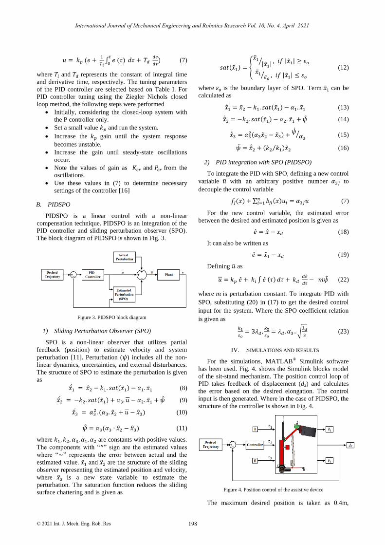
B. PIDSPO
PIDSPO is a linear control with a non-linear
compensation technique. PIDSPO is an integration of the
PID controller and sliding perturbation observer (SPO).
The block diagram of PIDSPO is shown in Fig. 3.
Figure 3. PIDSPO block diagram
1) Sliding Perturbation Observer (SPO)
SPO is a non-linear observer that utilizes partial
feedback (position) to estimate velocity and system
perturbation [11]. Perturbation (𝜓) includes all the non-
linear dynamics, uncertainties, and external disturbances.
The structure of SPO to estimate the perturbation is given
as
��1 = ��2 − 𝑘1. 𝑠𝑎𝑡(��1) − 𝛼1. ��1 (8)
��2 = −𝑘2. 𝑠𝑎𝑡(��1) + 𝛼3. 𝑢 − 𝛼2. ��1 + �� (9)
��3 = 𝛼32. (𝛼3. ��2 + 𝑢 − ��3) (10)
�� = 𝛼3(𝛼3 ∙ ��2 − ��3) (11)
where 𝑘1, 𝑘2, 𝛼3, 𝛼1, 𝛼2 are constants with positive values.
The components with “^” sign are the estimated values
where “~” represents the error between actual and the
estimated value. ��1 and ��2 are the structure of the sliding
observer representing the estimated position and velocity,
where ��3 is a new state variable to estimate the
perturbation. The saturation function reduces the sliding
surface chattering and is given as
𝑠𝑎𝑡(��1) = {
��1|��1|⁄ , 𝑖𝑓 |��1| ≥ 𝜀𝑜
��1𝜀𝑜
⁄ , 𝑖𝑓 |��1| ≤ 𝜀𝑜
(12)
where 𝜀𝑜 is the boundary layer of SPO. Term ��1 can be
calculated as
��1 = ��2 − 𝑘1. 𝑠𝑎𝑡(��1) − 𝛼1. ��1 (13)
��2 = −𝑘2. 𝑠𝑎𝑡(��1) − 𝛼2. ��1 + �� (14)
��3 = 𝛼32(𝛼3��2 − ��3) +
��𝛼3
⁄ (15)
�� = ��2 + (𝑘2 𝑘1⁄ )��2 (16)
2) PID integration with SPO (PIDSPO)
To integrate the PID with SPO, defining a new control
variable �� with an arbitrary positive number 𝛼3𝑗 to
decouple the control variable
𝑓𝑗(𝑥) + ∑ 𝑏𝑗𝑖(𝑥)𝑢𝑖 = 𝛼3𝑗��𝑛𝑖=1 (7)
For the new control variable, the estimated error
between the desired and estimated position is given as
�� = �� − 𝑥𝑑 (18)
It can also be written as
�� = ��1 − 𝑥𝑑 (19)
Defining �� as
𝑢 = 𝑘𝑝 �� + 𝑘𝑖 ∫ �� (𝜏) 𝑑𝜏 + 𝑘𝑑 𝑑��
𝑑𝜏− 𝑚�� (22)
where 𝑚 is perturbation constant. To integrate PID with
SPO, substituting (20) in (17) to get the desired control
input for the system. Where the SPO coefficient relation
is given as
𝑘1
𝜀𝑜= 3𝜆𝑑 ,
𝑘2
𝜀𝑜= 𝜆𝑑 , 𝛼3=√
𝜆𝑑
3 (23)
IV. SIMULATIONS AND RESULTS
For the simulations, MATLAB® Simulink software
has been used. Fig. 4. shows the Simulink blocks model
of the sit-stand mechanism. The position control loop of
PID takes feedback of displacement (d2) and calculates
the error based on the desired elongation. The control
input is then generated. Where in the case of PIDSPO, the
structure of the controller is shown in Fig. 4.
Figure 4. Position control of the assistive device
The maximum desired position is taken as 0.4m,
198
International Journal of Mechanical Engineering and Robotics Research Vol. 10, No. 4, April 2021
© 2021 Int. J. Mech. Eng. Rob. Res

which is the maximum extendable length of the linear
actuator used. The mass of the patient is considered as the
external disturbance because the dynamic equations were
evaluated without patients, as the patient mass varies
patient to patient. The maximum allowable weight is
80Kg where the torque required for a linear actuator to
hold the patient [17] is given as
𝑇ℎ𝑜𝑙𝑑 =F𝐷𝑝
2=
80×9.8×0.026
2= 10.192 Nm (22)
where 𝐹 is the force due to gravity and 𝐷𝑝 is the pitch
diameter of the threaded bar of the linear-actuator. The
simulations are performed for maximum allowable
parameters to check system response. Furthermore, the
system was linearized to observe the working of PIDSPO
more clearly. The linearized transfer function of the
prismatic joint obtained from (2), (3) and (4) is given as
𝑑2 =6.38𝑠4+9.389𝑠2
40𝑠6+2.392𝑠4 (23)
A. PID Controller
Initially, the PID controller was manually tuned using
the Ziegler Nichols closed-loop tuning method. The
obtained PID gains are given in Table II. Where the
response of the linear system presented in (23) with
manually tuned PID controller is shown in Fig. 5.
TABLE II. MANUALLY TUNED PID GAINS
Joint Gains
𝒌𝒑 𝒌𝒊 𝒌𝒅
d2 65 25 6.25
Figure 5. System response with manually tuned PID control
The controlled system with Ziegler Nichols tuned PID
has oscillations as the required torque to precisely control
the system was insufficient because of the small PID
gains. Therefore, the PID controller was auto-tuned using
Simulink auto-tuner, and the resulted gains of PID are
shown in Table III. The system response for the auto-
tuned PID is shown in Fig. 6.
TABLE III. AUTO-TUNED PID GAINS
Joint Gains
𝒌𝒑 𝒌𝒊 𝒌𝒅
d2 1232 1158 112.07
After auto-tuning the PID controller, the system
response shows better performance. But now, because of
high gains, the system confronts a sudden overshoot
because of high torque generated initially. This overshoot
is not feasible for the device holding the patient.
Therefore, the overshoot should be removed from the
system response. To do so, PID controller was integrated
with the non-linear compensation technique resulting in
PIDSPO a robust controller.
Figure 6. System response with manually tuned PID control
B. PIDSPO Controller
PIDSPO is a robust linear controller with a non-linear
perturbation compensation technique. Perturbation
includes all the non-linearities, system uncertainties and
disturbances. The integration procedure is illustrated in
Section III-B-2. As mentioned before that the patient
mass was considered as external disturbance to the
system, so introducing the resulting torque calculated in
(22) as disturbance to the system. Based on the block
diagram in Fig. 3, SPO will estimate this disturbance and
will compensates its effect from the system response to
make the system response oscillations and overshoot free.
PIDSPO parameters to control the system are given in
Table IV, and the resultant system response is presented
in Fig. 7.
TABLE IV. PIDSPO GAINS
Joint Gains
𝝀 𝜺𝒐 𝒌𝟏 𝒌𝟐 𝜶𝟑 𝒌𝒑 𝒌𝒊 𝒌𝒅
d2 15 1 45 675 2.23 20 12 8
Figure 7. System response with PIDSPO
199
International Journal of Mechanical Engineering and Robotics Research Vol. 10, No. 4, April 2021
© 2021 Int. J. Mech. Eng. Rob. Res

Now the system response with PIDSPO shows no
oscillations and overshoot and resulting in very smooth
output as compared to the response in Fig. 5 and Fig. 6,
even in the presence of external disturbance. This is
because of the disturbance compensation by SPO.
On the other hand, the actual and the estimated
perturbation is presented in Fig. 8. which shows that the
system tracks the actual perturbation very precisely.
Therefore, the system response is refined and robust.
Furthermore, another advantage of using PIDSPO is that
now the system is controllable with small PID gains as
compared to auto-tuned PID controller.
Figure 8. Actual and estimated perturbation
V. CONCLUSION
In this research, a new control scheme known as
PIDSPO has been proposed for an assistive device for a
paraplegic patient. The device was developed to help the
patients, but without an onboard control scheme, it is
unsafe for patients. Conventional PID and a new
paradigm of PID called PIDSPO were compared through
simulations, and it has been observed that PIDSPO
performs better than PID without oscillations in system
response and with small PID gains. The mass of the
patient was taken as an external disturbance as the mass
differs from patient to patient. Initially, the system was
linearized, and then an external torque (holding torque) as
the effect of patient mass was introduced as an external
disturbance. SPO estimated the holding torque according
to the presented mass very accurately and compensated
that from the system response and giving better results
with robust system performance. In the future, it is
intended to implement sliding mode control with sliding
perturbation observer (SMCSPO) to further improve the
system response with the actual system dynamics.
CONFLICT OF INTEREST
The authors declare no conflict of interest
AUTHOR CONTRIBUTIONS
HK conducted the research, proposed the algorithm,
and wrote the paper. SJA helped in the analysis of the
algorithm. MCL supervised the research. All the authors
had approved the final version.
ACKNOWLEDGMENT
This research was supported by the nuclear research
and development program through the National Research
Foundation of Korea (NRF) funded by the Ministry of
Science and ICT (MSIT, Korea). [NRF-
2019M2C9A1057807] and by the Technology Innovation
Program (10073147, Development of Robot
Manipulation Technology by Using Artificial Intelligence)
funded By the Ministry of Trade, Industry & Energy
(MOTIE, Korea).
REFERENCES
[1] I. Díaz, J. J. Gil, and E. Sánchez, "Lower-limb robotic
rehabilitation: Literature review and challenges," Journal of Robotics, vol. 2011, pp. no 759764, 1-11, 2011.
[2] O. Salah, A. A. Ramadan, S. Sessa, and A. A. Abo-Ismail, "A
systematic approach for design a low-cost mobility assistive device for elderly people," International Journal of Medical
Health, Biomedical, Bioengineering and Pharmaceutical
Engineering, vol. 5, pp. 36-41, 2011. [3] R. Kamnik and T. Bajd, "Standing-up robot: an assistive
rehabilitative device for training and assessment," Journal of
Medical Engineering & Technology, vol. 28, no. 2, pp. 74-80, 2004.
[4] A. Tsukahara, R. Kawanishi, Y. Hasegawa, and Y. Sankai, "Sit-
to-stand and stand-to-sit transfer support for complete paraplegic patients with robot suit HAL," Advanced Robotics, vol. 24, no.
11, pp. 1615-1638, 2010.
[5] F. Previdi, M. Ferrarin, I. Carpinella, and S. Savaresi, "Modelling and control of a device for rehabilitation of
paraplegic patients," in American Control Conference, pp. 2030-
2035, 2007. [6] J. Nikitczuk, B. Weinberg, P. K. Canavan, and C. Mavroidis,
"Active knee rehabilitation orthotic device with variable
damping characteristics implemented via an electrorheological fluid," IEEE/ASME Transactions on Mechatronics, vol. 15, no. 6,
pp. 952-960, 2009.
[7] S. Khan, M. F. Zeb, N. Ghafoor, S. Jamshed, M. R. Afzal, and A. Eizad, "Design of an assistance robot for patients suffering from
Paraplegia," in 2015 15th International Conference on Control,
Automation and Systems (ICCAS), pp. 830-834, 2015. [8] L. Khan, M. Irfan, and H. Ali, "Implementation of GA in
designing control system for paraplegic walking movement using
walker," World Applied Sciences Journal, vol. 7, no. 9, pp. 1164-1175, 2009.
[9] A. Abdullah and Z. Kausar, "Control of sit to stand mechanism
of assistive Device for paraplegics," Journal of Physics: Conference Series, vol. 1016, no. 1, pp. 1-5, 2018.
[10] H. Khan, S. J. Abbasi, K. D. Kallu, and M. C. Lee, "Robust
control design of 6-DOF robot for nuclear power plant dismantling," in Proc. 2019 IEEE International Conference on
RoboticsAutomation in Industry (ICRAI), 2019, pp. 1-7.
[11] K. D. Kallu, S. J. Abbasi, H. Khan, J. Wang, and M. C. Lee, "Implementation of a TSMCSPO controller on a 3-DOF
hydraulic manipulator for position tracking and sensor-less force
estimation," IEEE Access, vol. 7, pp. 177035-177047, 2019 [12] H. Khan, S. J. Abbasi, K. D. Kallu, and M.-C. Lee, "Feedback
control of sit-stand mechanism of an assistive device for
paraplegics," ICROS, pp. 3-4, 2019. [13] M. Khan and Z. Kausar, "Kinematics modeling and mechanism
configuration selection of a mechatronic assistive device for
paraplegic patients," in Proc.the 5th International Conference on Mechatronics and Control Engineering, pp. 27-32, 2016.
[14] J. J. Craig, "Manipulator dynamics," Introduction to Robotics:
Pearson/Prentice Hall, pp. 185-186, 2005. [15] F. Memon and C. Shao, "An optimal approach to online tuning
method for PID type iterative learning control," International Journal of Control, Automation and Systems, vol. 18, no. 8, pp.
1926-1935, 2020.
[16] M. Edu. "Tunning for PID controller." [Online]. Available:
http://faculty.mercer.edu/jenkins_he/documents/TuningforPIDCo
ntrollers.pdf (accessed).
[17] R. S. Khurmi and J. K. Gupta, "Power screws," Machine Design, pp. 624-676, 2005.
200
International Journal of Mechanical Engineering and Robotics Research Vol. 10, No. 4, April 2021
© 2021 Int. J. Mech. Eng. Rob. Res

Hamza Khan is doing M.S degree in
Mechanical Engineering from Pusan National
University, Busan, Korea since 2019. He received the B.S degree in Mechatronics
Engineering from Air University, Islamabad,
Pakistan in 2018. His research interests include non-linear control, robot manipulator and
system identification.
Saad Jamshed Abbasi is doing Ph.D. degree in Mechanical Engineering from Pusan National
University, Busan, Korea since 2018. He
Received the M.S degree in Mechanical Engineering from Pusan National University,
Busan, Korea in 2018. He received the B.S
degree in Mechatronics Engineering from Air University, Islamabad, Pakistan in 2015. His
research interests include non-linear control,
robot manipulator and system identification.
Min Cheol Lee received the B.S. degree in Mechanical Engineering from Pusan National
University, Busan, Korea in 1983, M.S. degree in Engineering Sciences and Ph.D. degree in
Applied Physics from University of Tsukuba,
Tsukuba, Japan in 1991, respectively. He was a Visiting Professor at North Carolina State
University from Aug. 2000 to Aug. 2001 and at
Perdue University from Aug.2009 toAug.2010, respectively. From 1991 to currently, he is a
Professor in the School of Mechanical Engineering of Pusan National
University, South Korea. His research interests include intelligent robot
control, autonomous mobile robot, medical robot, signal processing to
identify a system, robust control of a system, sensor application, and
mechatronics.
201
International Journal of Mechanical Engineering and Robotics Research Vol. 10, No. 4, April 2021
© 2021 Int. J. Mech. Eng. Rob. Res
Copyright © 2021 by the authors. This is an open access article
distributed under the Creative Commons Attribution License (CC BY-NC-ND 4.0), which permits use, distribution and reproduction in any
medium, provided that the article is properly cited, the use is non-commercial and no modifications or adaptations are made.