Embed Size (px)
Citation preview


1
Contents
1. Products Categories.................................................................................................................. 21.1 Composition of Ultrasonic flow meter .......................................................................... 21.2 Types of Converters ....................................................................................................... 21.3 Types of Flow/Temperature Transducers ....................................................................... 3
2. Check Components................................................................................................................... 33. Measuring Diagrams ................................................................................................................ 44. Converter Installation and Wiring Diagram ............................................................................. 5
4.1 Separated Mounting ....................................................................................................... 54.2 Fix mounting .................................................................................................................. 84.3 Module type ................................................................................................................... 9
5. Transducer Introduction and Wiring Diagram ....................................................................... 105.1 Clamp on type transducer.............................................................................................. 105.2 Insertion type transducer .............................................................................................. 115.3 Inline type transducer ................................................................................................... 12
6. Display and Operation ............................................................................................................ 136.1 Display and keyboard.................................................................................................... 136.2 Operation ...................................................................................................................... 136.3 Menu Details ................................................................................................................ 146.4 Quick setup of measured parameters ........................................................................... 21
7. Transducers Installation ......................................................................................................... 227.1 Choose installation points ............................................................................................ 227.2 Clamp on transducer Installation ................................................................................. 247.3 Insertion type transducer installation ........................................................................... 277.4 In-line type transducer installation .............................................................................. 327.5 Check Installation ........................................................................................................ 33
8. Finish Installation................................................................................................................... 34
Welcome to use the new generation ultrasonic flow meter made of our patented technology.UF2000 Series Ultrasonic Flow/Heat Meters utilize the transit-time principle to measure thevelocity of relatively clean liquids in full pipes.
The purpose of this guide is to provide installation procedures and basic operating instructions forUF2000 Series Ultrasonic Flow/Heat Meters.
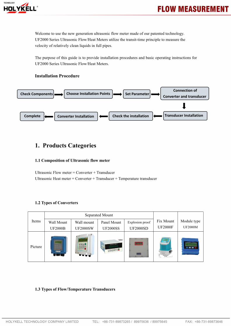
Installation Procedure
1. Products Categories
1.1 Composition of Ultrasonic flow meter
Ultrasonic Flow meter = Converter + TransducerUltrasonic Heat meter = Converter + Transducer + Temperature transducer
1.2 Types of Converters
ItemsSeparated Mount
Fix MountUF2000F
Module typeUF2000M
Wall MountUF2000B
Wall mountUF2000SW
Panel MountUF2000SS
Explosion proof
UF2000SD
Picture
1.3 Types of Flow/Temperature Transducers
Check Components Choose Installation Points Set ParameterConnection of
Converter and transducer
Transducer InstallationCheck the installationConverter InstallationComplete

3
Flow Transducer Picture Model Measuring range Temperature
Clamp onTS-2 (small) DN25-100
-30 ~ 90℃TM-1 (medium) DN50-700
TL-1 (large) DN300-6000
High temp.Clamp on
TS-2-HT (small) DN25-100-30 ~ 160℃TM-1-HT (medium) DN50-700
TL-1-HT (large) DN300-6000
InsertionTC-1 (standard) DN50-6000
-30 ~ 160℃TC-2 (extended)TP-1 (parallel) DN200-6000
Inline Standard DN15-1000 -30 ~160℃
TemperatureTransducer
Picture Model Measuringrange
Temperature Cutoff water
Clamp on CT-1 ≥ DN50 -40 ~ 160℃ No need
Insertion TCT-1 ≥ DN50 -40 ~ 160℃ Need
Insertionunder pressure PCT-1 ≥ DN50 -40 ~ 160℃ No need
Insertionsmall sizes SCT-1 < DN50 -40 ~ 160℃ Need
2. Check Components1. Please check you have all the components in the order.2. All codes on the converter and transducers should be matched. They are used in sets.
Transducer Codes Transducer Codes on Converter
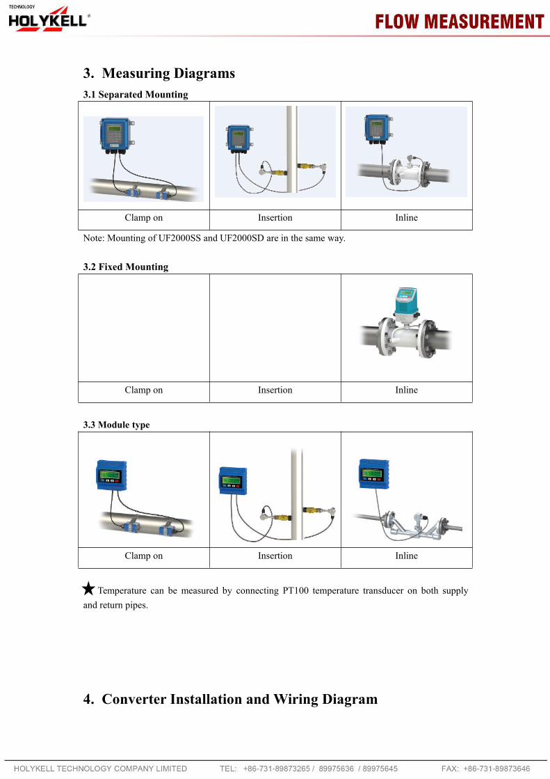
3. Measuring Diagrams3.1 Separated Mounting
Clamp on Insertion Inline
Note: Mounting of UF2000SS and UF2000SD are in the same way.
3.2 Fixed Mounting
Clamp on Insertion Inline
3.3 Module type
Clamp on Insertion Inline
Temperature can be measured by connecting PT100 temperature transducer on both supplyand return pipes.
4. Converter Installation and Wiring Diagram

5
4.1 Separated Mounting
UF2000B Installation Instruction
Wall mounting: Fix the converter with 4 Φ6 expansion bolts or normal nails.
DIN-rail mounting by using rail fixing clamps.
DIN-rail mounting by using PCB bracket
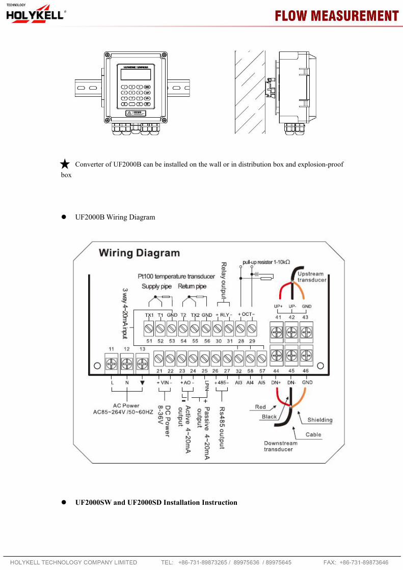
Converter of UF2000B can be installed on the wall or in distribution box and explosion-proofbox
UF2000BWiring Diagram
UF2000SW and UF2000SD Installation Instruction

7
Thickness: 75mm Thickness: 165mm
UF2000SW and UF2000SDWiring Diagram
UF2000SS Installation and Wiring Diagram
Explosion-proof grade: DⅡBT5Fix the converter with 4 Φ8 expansion bolts.
Wall mounting: Fix the converterwith 4 Φ6 expansion bolts.
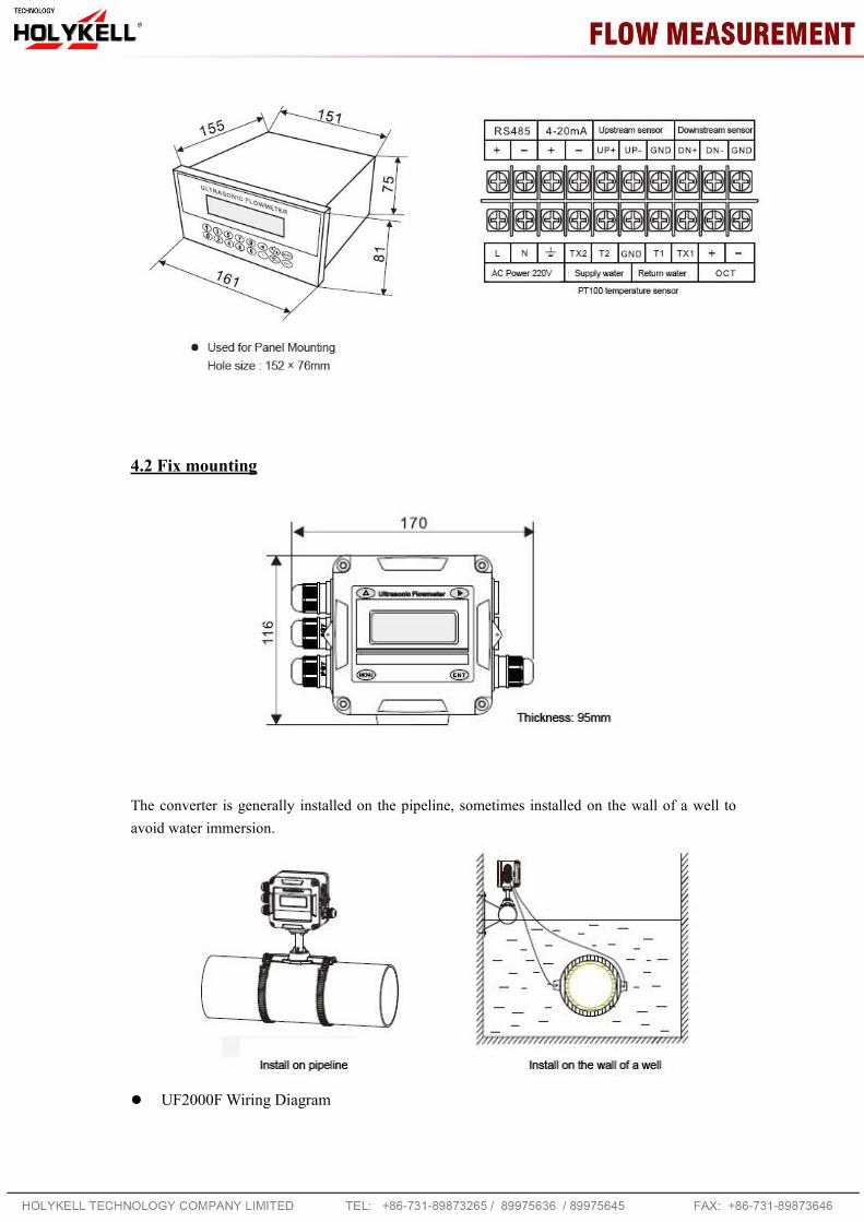
4.2 Fix mounting
The converter is generally installed on the pipeline, sometimes installed on the wall of a well toavoid water immersion.
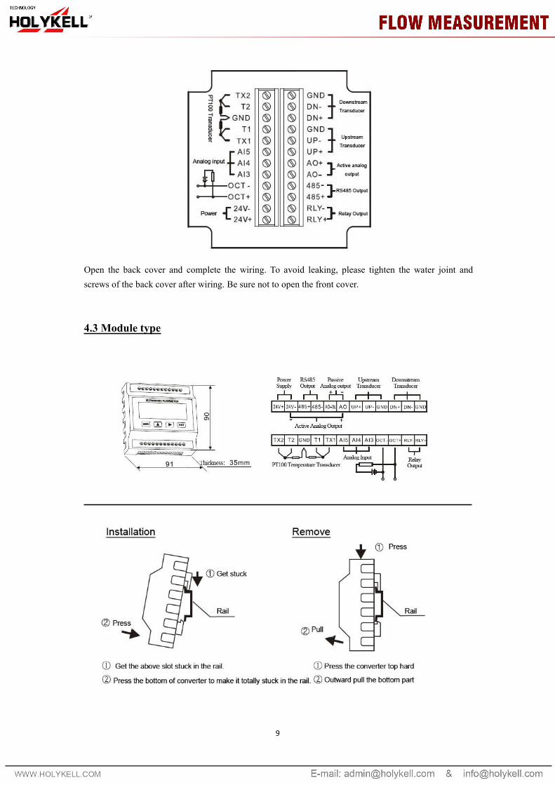
UF2000FWiring Diagram
9
Open the back cover and complete the wiring. To avoid leaking, please tighten the water joint andscrews of the back cover after wiring. Be sure not to open the front cover.
4.3 Module type

5. Transducer Introduction and Wiring Diagram
5.1 Clamp on type transducer
Introduction
Wiring Diagram
5.2 Insertion type transducer

11
Introduction
Wiring Diagram
5.3 Inline type transducer
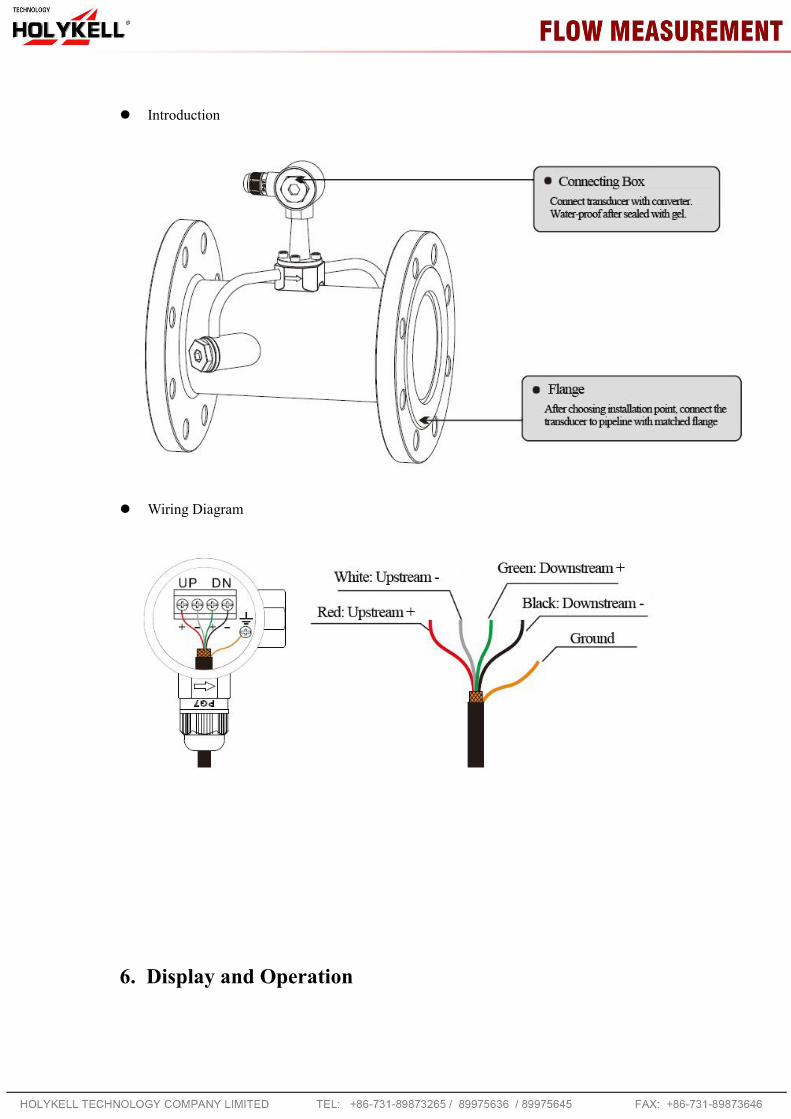
Introduction
Wiring Diagram
6. Display and Operation
13
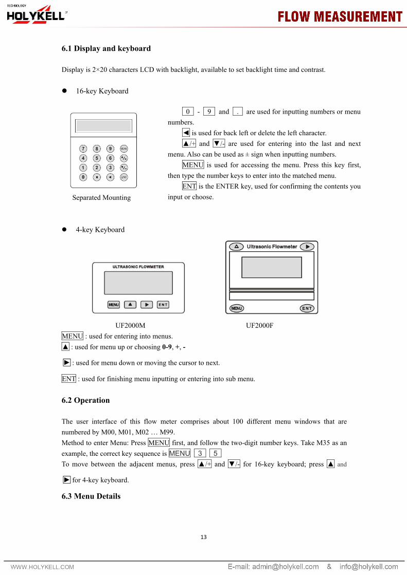
6.1 Display and keyboard
Display is 2×20 characters LCD with backlight, available to set backlight time and contrast.
16-key Keyboard
Separated Mounting
4-key Keyboard
UF2000M UF2000FMENU : used for entering into menus.▲ : used for menu up or choosing 0-9, +, -
□► : used for menu down or moving the cursor to next.
ENT : used for finishing menu inputting or entering into sub menu.
6.2 Operation
The user interface of this flow meter comprises about 100 different menu windows that arenumbered by M00, M01, M02 … M99.Method to enter Menu: Press MENU first, and follow the two-digit number keys. Take M35 as anexample, the correct key sequence is MENU 3 5To move between the adjacent menus, press ▲/+ and ▼/- for 16-key keyboard; press ▲ and
□► for 4-key keyboard.
6.3 Menu Details
0 - 9 and . are used for inputting numbers or menunumbers.
◄ is used for back left or delete the left character.▲/+ and ▼/- are used for entering into the last and next
menu. Also can be used as ± sign when inputting numbers.MENU is used for accessing the menu. Press this key first,
then type the number keys to enter into the matched menu.ENT is the ENTER key, used for confirming the contents you
input or choose.

MenuNo.
Details
M00 Display flow rate and NET totalizer. Unit selection in M30~M32.
M01 Display flow rate and velocity. Unit selection in M30~M32.
M02 Display flow rate and POS(positive) totalizer. Unit selection in M30~M32.
M03 Display flow rate and NEG(negative) totalizer.Unit selection in M30~M32.
M04 Display date and time, flow rate.
M05 Display heat flow rate and total heat. Unit selection in M84 and M88.
M06 Display temperatures, inlet T1, outlet T2
M07 Display analog inputs, AI3/AI4
M08 Display system error codes. ‘R’ stands for normal.
M09 Display today’s total NET flow
M10 Input outer perimeter.*M11 Input outer diameter. Available range is 0 to 18000mm.*M12 Input pipe wall thickness*M13 Input inner diameter.*M14 Select pipe material.
M15 Input sound velocity of the pipe material.
M16 Select lining material.
M17 Input sound velocity of the lining material.
M18 Input the lining thickness.
M19 Input the absolute roughness of pipe inner wall.
*M20 Select the liquid type.
M21 Input sound velocity of the liquid.
M22 Input viscosity of the liquid.
*M23 Select the transducer type. Over 20 types can be selected.*M24 Select the mounting method of transducer.
*M25 Display the transducer mounting distance.
*M26
0 Use RAM setting: A switch for the parameters in flash memory will be loaded whenpower is turned on. The default option is that the parameters will be loaded. If thisswitch is not turned on, the system will try to use the parameters in the system RAM, ifthese parameters are ok, otherwise the system will load the parameters in flash memory1 Solidity setting: Function to store the current parameters into the flash memory, sothat these parameters will be solidified and will be loaded as the default parametersevery time when power is turned on.
M27 To save the installation point parameter.
M28Maintain the last good value when poor signal condition occurs. YES is the defaultsetup.
M29 Setup a signal strength as empty pipe. For example input 65, it means the pipe is treated

15
as empty pipe when the signal is less than 65, and the flow rate display is 0.M30 Select metric or british system unit.M31 Select flow rate unit.
M32 Select totalizer flow unit.
M33Select totalizer multiple factor.The multiplying factor ranges from 0.001 to 10000. Factory default is 1
M34 Turn on or turn off the NET totalizerM35 Turn on or turn off the POS (positive) totalizerM36 Turn on or turn off the NEG(negative) totalizerM37 Restore factory settings. Totalizer reset.
M38Manual totalizer used for easier calibration. Press a key to start and press a key to stopthe manual totalizer.
M39 Language selection. there are Chinese+English+Italian or English+Italian+Turkish
*M40Damping factor. The damping factor ranges from 0 to 999 seconds.0 means there is no damping. Factory default is 10 seconds
*M41 Cut-off low flow rate (or zero flow rate) to avoid invalid accumulation.
M42Zero calibration/Zero point setup. Make sure the liquid in the pipe is not running whiledoing the setup.
M43 Clear the zero point value, and restore original value.M44 Manual Zero point . Set up a flow bias. Generally this value should be 0.
M45Flow rate scale factor. The default value is ‘1’.Keep this value as ‘1’, when no calibration has been made.
M46
Networks address identification number. Any integer can be entered except 13(0DH,carriage return), 10 (0AH, line feeding), 42 (2AH), 38, 65535.Every set of the instrument in a network environment should have a unique IDN. Pleaserefer to the chapter for communication.
M47System locker to avoid modification of the system parameters.If password is forgotten, you could send a command ‘LOCK0’ to the serial input tounlock. Or you can write 0 to REGISTER49-50 under MODBUS protocol.
M48Entry to linearity correcting data inputs. By using of this function, the non-linearity offlow meter will be corrected. Correcting data shall be obtained by careful calibration.
M49Displays the input contents for the serial port.By checking the displays, you can know if the communication is ok.
M50Switches for the built-in data logger. There are as many as 22 different items can bechosen. To turn this function, select ‘YES’ the system will ask for selecting the items.
M51 Time set for timing output.(data logger or printer)
M52
Data logging direction control.(1) If ‘Send to RS485’ is selected, all the data produced by the data logger will betransmitted out through the RS-232/RS485 interface(2) If ‘To the internal serial BUS is selected, the data will be transmitted to the internalserial bus which allows a thermal printer, or a 4-20mA analog output module, to beconnected to it.
M53Display analog inputs, AI5, current value and its corresponding temperature or pressureor liquid level value.
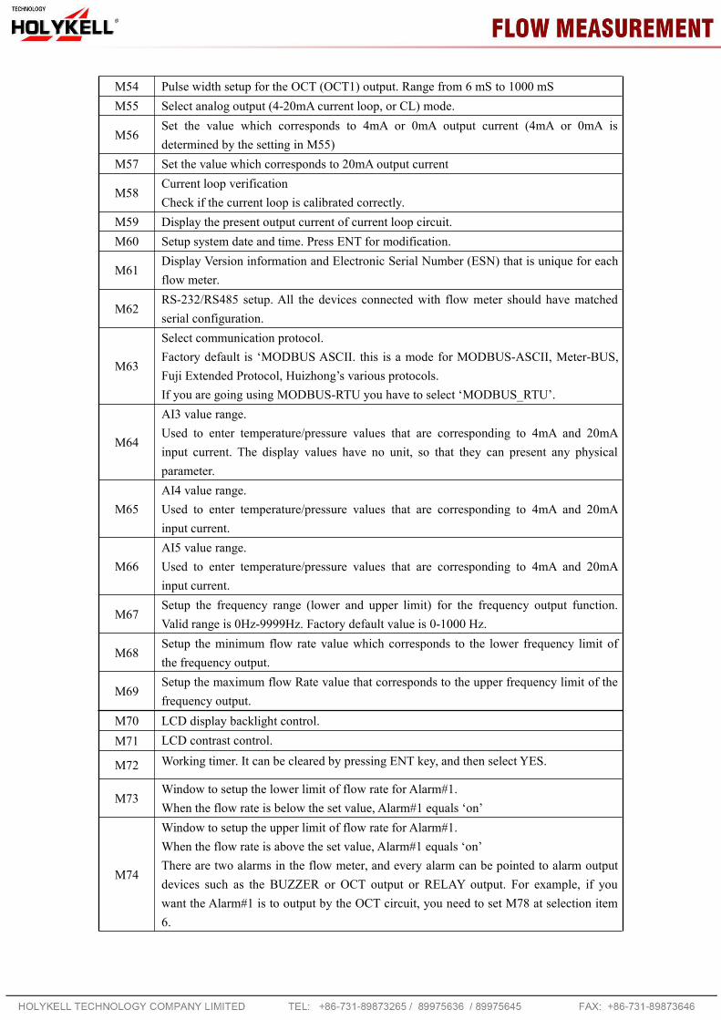
M54 Pulse width setup for the OCT (OCT1) output. Range from 6 mS to 1000 mSM55 Select analog output (4-20mA current loop, or CL) mode.
M56Set the value which corresponds to 4mA or 0mA output current (4mA or 0mA isdetermined by the setting in M55)
M57 Set the value which corresponds to 20mA output current
M58Current loop verificationCheck if the current loop is calibrated correctly.
M59 Display the present output current of current loop circuit.M60 Setup system date and time. Press ENT for modification.
M61Display Version information and Electronic Serial Number (ESN) that is unique for eachflow meter.
M62RS-232/RS485 setup. All the devices connected with flow meter should have matchedserial configuration.
M63
Select communication protocol.Factory default is ‘MODBUS ASCII. this is a mode for MODBUS-ASCII, Meter-BUS,Fuji Extended Protocol, Huizhong’s various protocols.If you are going using MODBUS-RTU you have to select ‘MODBUS_RTU’.
M64
AI3 value range.Used to enter temperature/pressure values that are corresponding to 4mA and 20mAinput current. The display values have no unit, so that they can present any physicalparameter.
M65AI4 value range.Used to enter temperature/pressure values that are corresponding to 4mA and 20mAinput current.
M66AI5 value range.Used to enter temperature/pressure values that are corresponding to 4mA and 20mAinput current.
M67Setup the frequency range (lower and upper limit) for the frequency output function.Valid range is 0Hz-9999Hz. Factory default value is 0-1000 Hz.
M68Setup the minimum flow rate value which corresponds to the lower frequency limit ofthe frequency output.
M69Setup the maximum flow Rate value that corresponds to the upper frequency limit of thefrequency output.
M70 LCD display backlight control.M71 LCD contrast control.
M72 Working timer. It can be cleared by pressing ENT key, and then select YES.
M73Window to setup the lower limit of flow rate for Alarm#1.When the flow rate is below the set value, Alarm#1 equals ‘on’
M74
Window to setup the upper limit of flow rate for Alarm#1.When the flow rate is above the set value, Alarm#1 equals ‘on’There are two alarms in the flow meter, and every alarm can be pointed to alarm outputdevices such as the BUZZER or OCT output or RELAY output. For example, if youwant the Alarm#1 is to output by the OCT circuit, you need to set M78 at selection item6.
17
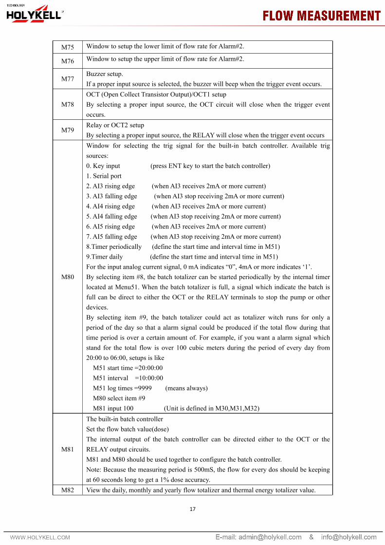
M75 Window to setup the lower limit of flow rate for Alarm#2.
M76 Window to setup the upper limit of flow rate for Alarm#2.
M77Buzzer setup.If a proper input source is selected, the buzzer will beep when the trigger event occurs.
M78OCT (Open Collect Transistor Output)/OCT1 setupBy selecting a proper input source, the OCT circuit will close when the trigger eventoccurs.
M79Relay or OCT2 setupBy selecting a proper input source, the RELAYwill close when the trigger event occurs
M80
Window for selecting the trig signal for the built-in batch controller. Available trigsources:0. Key input (press ENT key to start the batch controller)1. Serial port2. AI3 rising edge (when AI3 receives 2mA or more current)3. AI3 falling edge (when AI3 stop receiving 2mA or more current)4. AI4 rising edge (when AI3 receives 2mA or more current)5. AI4 falling edge (when AI3 stop receiving 2mA or more current)6. AI5 rising edge (when AI3 receives 2mA or more current)7. AI5 falling edge (when AI3 stop receiving 2mA or more current)8.Timer periodically (define the start time and interval time in M51)9.Timer daily (define the start time and interval time in M51)For the input analog current signal, 0 mA indicates “0”, 4mA or more indicates ‘1’.By selecting item #8, the batch totalizer can be started periodically by the internal timerlocated at Menu51. When the batch totalizer is full, a signal which indicate the batch isfull can be direct to either the OCT or the RELAY terminals to stop the pump or otherdevices.By selecting item #9, the batch totalizer could act as totalizer witch runs for only aperiod of the day so that a alarm signal could be produced if the total flow during thattime period is over a certain amount of. For example, if you want a alarm signal whichstand for the total flow is over 100 cubic meters during the period of every day from20:00 to 06:00, setups is likeM51 start time =20:00:00M51 interval =10:00:00M51 log times =9999 (means always)M80 select item #9M81 input 100 (Unit is defined in M30,M31,M32)
M81
The built-in batch controllerSet the flow batch value(dose)The internal output of the batch controller can be directed either to the OCT or theRELAY output circuits.M81 and M80 should be used together to configure the batch controller.Note: Because the measuring period is 500mS, the flow for every dos should be keepingat 60 seconds long to get a 1% dose accuracy.
M82 View the daily, monthly and yearly flow totalizer and thermal energy totalizer value.

The totalizer values and errors for the last 64 days, 32 last 32 months and last 2 years arestored in the RAM memory, To view them, use the ‘ENT’ and ‘UP’ ‘Down’ keys.
M83
Automatic Amending Function for automatic offline compensation.Select ‘YES’ to enable this function, select ‘NO’ to disable it.When the function is enabled, The flow meter will estimate the average flow uncounted(or ‘lost’) during the offline session and add the result to the totalizer.The estimation of the uncounted flow is made by computing the product of the offlinetime period and the average flow rate, which is the average of the flow rate before goingoffline and the one after going on line.
M84Set the thermal energy unit:0. GJ 1. KC 2.KWh 3. BTU
M85Select temperature sources0. from T1,T2 (factory default)1. from AI3,AI4
M86
Select the Specific Heat Value.Factory default is ‘GB’. Under this setting, the flow meter will calculate the enthalpy ofwater based on the international standard.If the fluid is other than water, you should select option ‘1. Fixed Specific Heat’, andenter the specific heat value of the fluid.
M87 Turn on or turn off the Energy totalizer.
M88Select thermal energy totalizer multiplying factor.Factory default is ‘1’.
M891. Display the temperature difference2. Window for entering the lowest temperature difference.
*M90
Display signal strengths S (one for upstream and one for downstream), and signal qualityQ value.Signal strength is presented by 00.0 to 99.9, the bigger the value, the bigger the signalstrength will be, and more reliable readings will be made.Q value is presented by 00 to 99, the bigger the better. It should at least be great than 50for normal operations.
*M91
Displays the Time Ratio between the Measured Total Transit Time and the Calculatedtime. If the pipe parameters are entered correctly and the transducers are properlyinstalled, the ratio value should be in the range of 100±3%. Otherwise the enteredparameters and the transducer installation should be checked.
M92Displays the estimated fluid sound velocity. If this value has an obvious difference withthe actual fluid sound speed, pipe parameters entered and the transducer installationshould be checked again.
M93 Displays total transit time and delta time(transit time difference)
M94Displays the Reynolds number and the pipe factor used by the flow rate measurementprogram. Pipe factor is calculated based on the ratio of the line-average velocity and thecross-section average velocity.
M95(1) Display the positive and negative energy totalizers(2) Upon entering this window, the circular display function will be startedautomatically. The following windows will be displayed one by one, each window will

19
stay for 8 seconds: M95>>M00>>M01>>M02>>M02>>M03>>M04>>M05>>M06>>M07>>M08>>M90>>M91>>M92>> M93>>M94>>M95. This function allows the user to visit all the important information withoutany manual action.To stop this function, simply press a key. Or switch to a window other than M95.
M96 This is not a window but a command for the thermal printer to advance 5 lines of paper.
M97This is not a window but a command to print the pipe parameters.By default, the produced data will be directed to the internal serial bus (thermal printer).You can also direct those data to the serial communication port.
M98This is not a window but a command to print the diagnostic information.By default, the produced data will be directed to the internal serial bus (thermal printer).You can also direct those data to the serial communication port.
M99
This is not a window but a command to copy the current display window. By default, theproduced data will be directed to the internal serial bus (thermal printer). You can alsodirect those data to the serial communication port.By use of the window copying function, you can hardcopy very window displayingmanually by switching windows, or you can obtain the window displaying data bycommunication.
M+0Browse the 32 recorded instrument power-on and power-off date and time with the flowrate at the time of power on and off
M+1Displays the total working time of the flow meter.When the backup battery is removed, the total working time will be reset to zero.
M+2 Displays the last power-off date and timeM+3 Displays the last power-off flow rateM+4 Displays how many times of has been powered on and powered off.
M+5
A scientific calculator for the convenience of field working.All the values are in single accuracy.The calculator can be used while the flow meter is conducting flow measurement.Water density and PT100 temperature can also be found in this function.
M+6
Set fluid sound speed thresholdWhenever the estimated sound speed (displayed in M92) exceeds this threshold, analarms signal will be generated and can transmitted to BUZZER or OCT or RELAY.This function can used to produce an alarm or output when fluid material changes.
M+7 Displays total flow for this month(only for the time past)M+8 Displays total flow for this year(only for the time past)
M+9Display the not-working total time in seconds. The total failure timer will also includethe time when power off, if the back-up battery is applied.
M.2 Entry to solidify the zero point. Password protected.
M.5
Setup the Q value threshold.If the present Q is below this threshold, flow rate will be set to 0.This function is useful when flow meter is installed in noisy environment or on airypipes.
M.8 The maximum flow rates for today and this month.M.9 Serial port tester with CMM command output for very second.
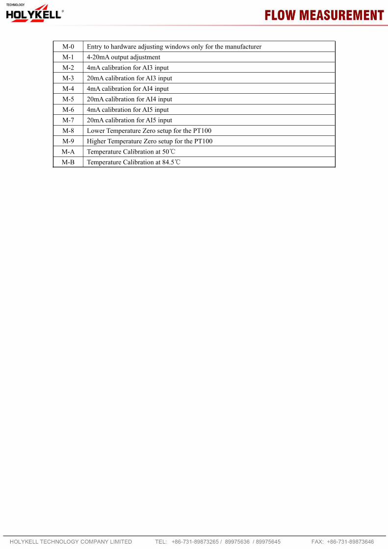
M-0 Entry to hardware adjusting windows only for the manufacturerM-1 4-20mA output adjustmentM-2 4mA calibration for AI3 inputM-3 20mA calibration for AI3 inputM-4 4mA calibration for AI4 inputM-5 20mA calibration for AI4 inputM-6 4mA calibration for AI5 inputM-7 20mA calibration for AI5 inputM-8 Lower Temperature Zero setup for the PT100M-9 Higher Temperature Zero setup for the PT100M-A Temperature Calibration at 50℃M-B Temperature Calibration at 84.5℃
21
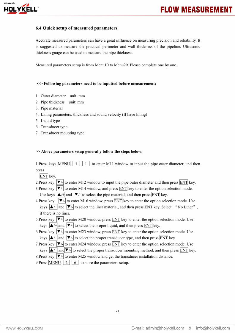
6.4 Quick setup of measured parameters
Accurate measured parameters can have a great influence on measuring precision and reliability. Itis suggested to measure the practical perimeter and wall thickness of the pipeline. Ultrasonicthickness gauge can be used to measure the pipe thickness.
Measured parameters setup is from Menu10 to Menu29. Please complete one by one.
>>> Following parameters need to be inputted before measurement:
1. Outer diameter unit: mm2. Pipe thickness unit: mm3. Pipe material4. Lining parameters: thickness and sound velocity (If have lining)5. Liquid type6. Transducer type7. Transducer mounting type
>> Above parameters setup generally follow the steps below:
1.Press keys MENU 1 1 to enter M11 window to input the pipe outer diameter, and thenpressENT key.
2.Press key ▼/- to enter M12 window to input the pipe outer diameter and then press ENT key.3.Press key ▼/- to enter M14 window, and press ENT key to enter the option selection mode.Use keys ▲/+ and ▼/- to select the pipe material, and then press ENT key.
4.Press key ▼/- to enter M16 window, press ENT key to enter the option selection mode. Usekeys ▲/+ and ▼/- to select the liner material, and then press ENT key. Select “No Liner”,if there is no liner.
5.Press key ▼/- to enter M20 window, press ENT key to enter the option selection mode. Usekeys ▲/+ and ▼/- to select the proper liquid, and then press ENT key.
6.Press key ▼/- to enter M23 window, press ENT key to enter the option selection mode. Usekeys ▲/+ and ▼/- to select the proper transducer type, and then press ENT key.
7.Press key ▼/- to enter M24 window, press ENT key to enter the option selection mode. Usekeys ▲/+ and▼/- to select the proper transducer mounting method, and then press ENT key.
8.Press key ▼/- to enter M25 window and get the transducer installation distance.9.Press MENU 2 6 to store the parameters setup.
7. Transducers Installation
7.1 Choose installation points
Proper installation point is a key for transducer installation. Following factors must be considered:Full filled pipeline, shaking, steady flow, scaling, temperature, pressure, EMI, instrument well.
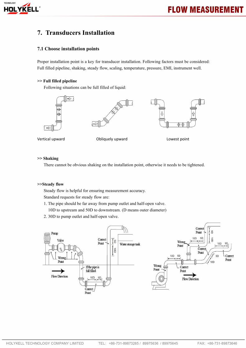
>> Full filled pipelineFollowing situations can be full filled of liquid:
Vertical upward Obliquely upward Lowest point
>> ShakingThere cannot be obvious shaking on the installation point, otherwise it needs to be tightened.
>>Steady flowSteady flow is helpful for ensuring measurement accuracy.Standard requests for steady flow are:1. The pipe should be far away from pump outlet and half-open valve.10D to upstream and 50D to downstream. (D means outer diameter)
2. 30D to pump outlet and half-open valve.
23
>> ScalingThe inside scaling would have bad effect on ultrasonic signal transmission, and would
decrease the inner diameter as well. As a result, the measurement accuracy can not be guaranteed.Please try to avoid choosing the installation point with inside scaling.
>>TemperatureThe liquid temperature on installation point should be in the working range of transducers.
Please try to choose the point with lower temperature. Avoid to choose points like the outlet ofboiler water and heat exchanger. Return water pipe would be better.Temperature range of standard clamp on and insertion transducers: -30 ~ 90℃Temperature range of high temperature clamp on and insertion transducers: -30 ~ 160℃
>>PressureThe maximum pressure for standard insertion and inline transducer is 1.6MPaOut of this range need customized.
>>EMI (electromagnetic interference)The ultrasonic flow meter, transducer and signal cable can be easily interfered by interference
sources such as frequency changer, radio station, microwave station, GSM base station andhigh-tension cable. Please try to avoid these interference sources when choosing installationpoints.The shield layer of flow meter, transducer and signal cable should be connected to earth.Better to use isolated power supply. Do not use the same power supply with the frequency
converter.
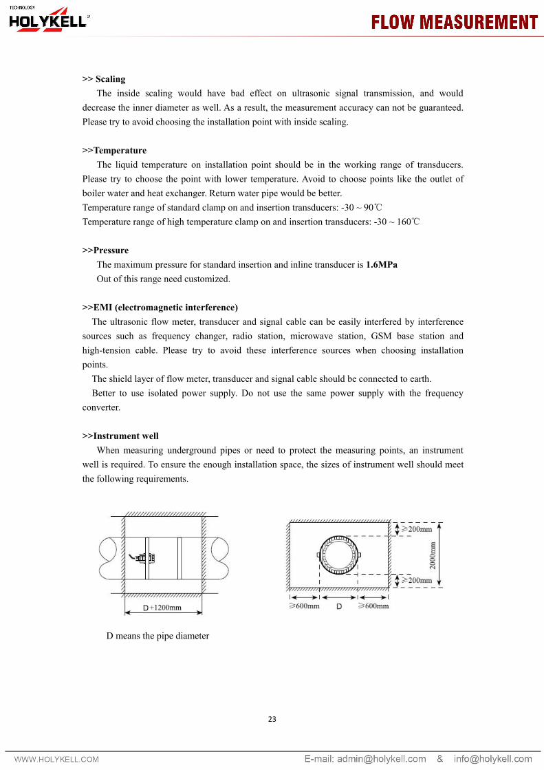
>>Instrument wellWhen measuring underground pipes or need to protect the measuring points, an instrument
well is required. To ensure the enough installation space, the sizes of instrument well should meetthe following requirements.
D means the pipe diameter
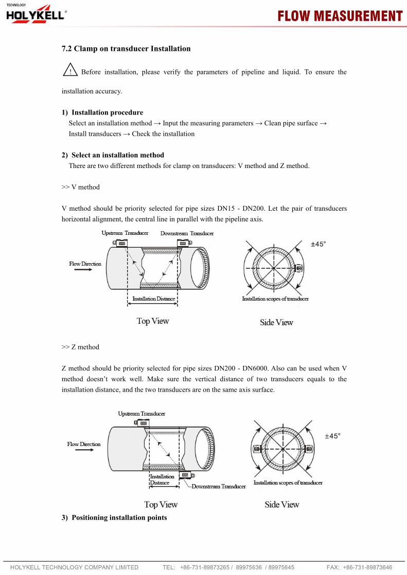
7.2 Clamp on transducer Installation
△! Before installation, please verify the parameters of pipeline and liquid. To ensure the
installation accuracy.
1) Installation procedureSelect an installation method → Input the measuring parameters → Clean pipe surface →Install transducers → Check the installation
2) Select an installation methodThere are two different methods for clamp on transducers: V method and Z method.
>> V method
V method should be priority selected for pipe sizes DN15 - DN200. Let the pair of transducershorizontal alignment, the central line in parallel with the pipeline axis.
>> Z method
Z method should be priority selected for pipe sizes DN200 - DN6000. Also can be used when Vmethod doesn’t work well. Make sure the vertical distance of two transducers equals to theinstallation distance, and the two transducers are on the same axis surface.
3) Positioning installation points
25
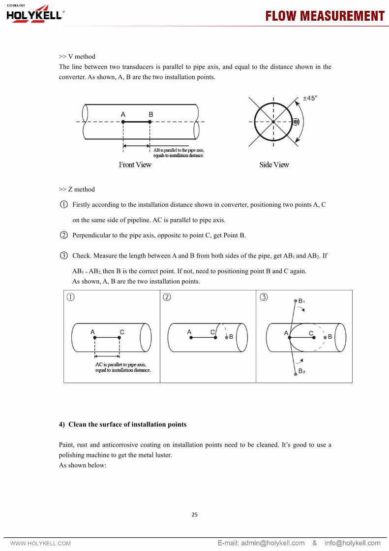
>> V methodThe line between two transducers is parallel to pipe axis, and equal to the distance shown in theconverter. As shown, A, B are the two installation points.
>> Z method
○1 Firstly according to the installation distance shown in converter, positioning two points A, C
on the same side of pipeline. AC is parallel to pipe axis.
○2 Perpendicular to the pipe axis, opposite to point C, get Point B.
○3 Check. Measure the length between A and B from both sides of the pipe, get AB1 and AB2. If
AB1 =AB2, then B is the correct point. If not, need to positioning point B and C again.As shown, A, B are the two installation points.
4) Clean the surface of installation points
Paint, rust and anticorrosive coating on installation points need to be cleaned. It’s good to use apolishing machine to get the metal luster.As shown below:

5) Install transducers
After transducer wiring and sealing, please evenly smear 2-3mm couplant on the transduceremitting surface. Then put the transducers on the installation points, fixed with steel belt or steelrope.
6) Check Installation
Please see details in Chapter 7.5
7.3 Insertion type transducer installation

27
△! Before installation, please verify the parameters of pipeline and liquid. To ensure the
installation accuracy.
1) Installation procedureSelect an installation method → Input the measuring parameters → Positioning installation points→ Fix ball valve base→ Open hole under pressure→ Install transducers → Check the installation
2) Select installation method and positioning installation pointsInsertion type transducers are suitable for pipe sizes > 50mm.Two different installation methods: V method and Z method. Generally use Z method, only use Vmethod for lack of space.
>> V methodV method can be used for DN50mm - 300mm. Let the pair of transducers horizontal alignment,
the central line in parallel with the pipeline axis, and the transmit direction mush be opposite.
>> Z methodZ method can be used for all pipes > DN50mm. Make sure the vertical distance of two
transducers equals to the installation distance, and the two transducers are on the same axis surface.The transmit direction mush be opposite.
>> Parallel insertion
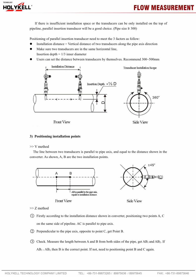
If there is insufficient installation space or the transducers can be only installed on the top ofpipeline, parallel insertion transducer will be a good choice. (Pipe size ≥ 300)
Positioning of parallel insertion transducer need to meet the 3 factors as follow: Installation distance = Vertical distance of two transducers along the pipe axis direction Make sure two transducers are in the same horizontal line,
Insertion depth = 1/3 inner diameter Users can set the distance between transducers by themselves. Recommend 300~500mm
3) Positioning installation points
>> V methodThe line between two transducers is parallel to pipe axis, and equal to the distance shown in the
converter. As shown, A, B are the two installation points.
>> Z method
○1 Firstly according to the installation distance shown in converter, positioning two points A, C
on the same side of pipeline. AC is parallel to pipe axis.
○2 Perpendicular to the pipe axis, opposite to point C, get Point B.
○3 Check. Measure the length between A and B from both sides of the pipe, get AB1 and AB2. If
AB1 =AB2, then B is the correct point. If not, need to positioning point B and C again.

29
As shown, A, B are the two installation points.
4) Fix ball valve base
>> Welding FixFor carbon steel pipes, the ball valve base can be welded directly. Make sure that the central
point of ball valve base is overlapped with the transducer installation point.Matters need attention: Please take the PTFE sealing gasket out from the base before welding. Please clean the pipe surface around welding point before welding. Pay attention that there
should not be any air hole during welding, which can avoid leaking. Welding strength mustbe ensured.
Do not sputter welding slag on the base thread. Non-deformation of base during welding.After welding, tighten ball valve into the base.
>> Pipe hoop FixFor pipes can’t be welded directly like cast iron pipe, cement pipe, copper pipe and composite
pipe, customized pipe hoop is recommended.The hoop center should be overlapped with the transducer installation point. Please compress thesealing gasket tightly to avoid leaking.
5) Open hole
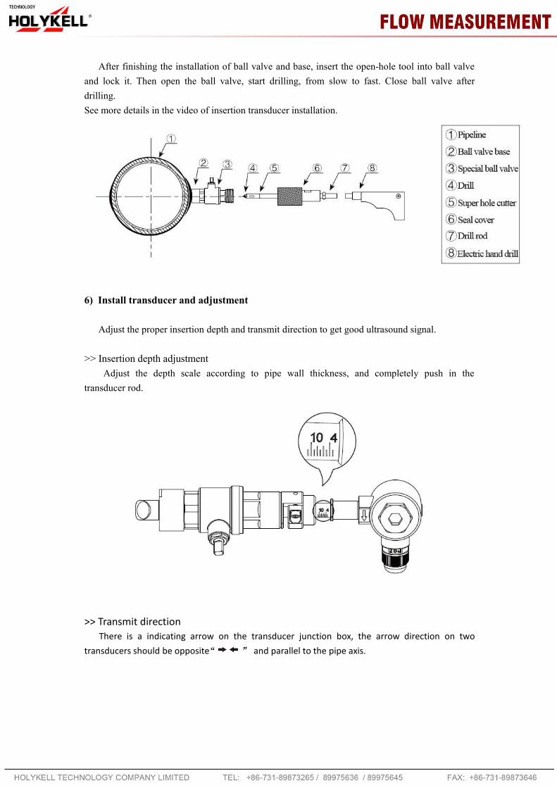
After finishing the installation of ball valve and base, insert the open-hole tool into ball valveand lock it. Then open the ball valve, start drilling, from slow to fast. Close ball valve afterdrilling.See more details in the video of insertion transducer installation.
6) Install transducer and adjustment
Adjust the proper insertion depth and transmit direction to get good ultrasound signal.
>> Insertion depth adjustmentAdjust the depth scale according to pipe wall thickness, and completely push in the
transducer rod.
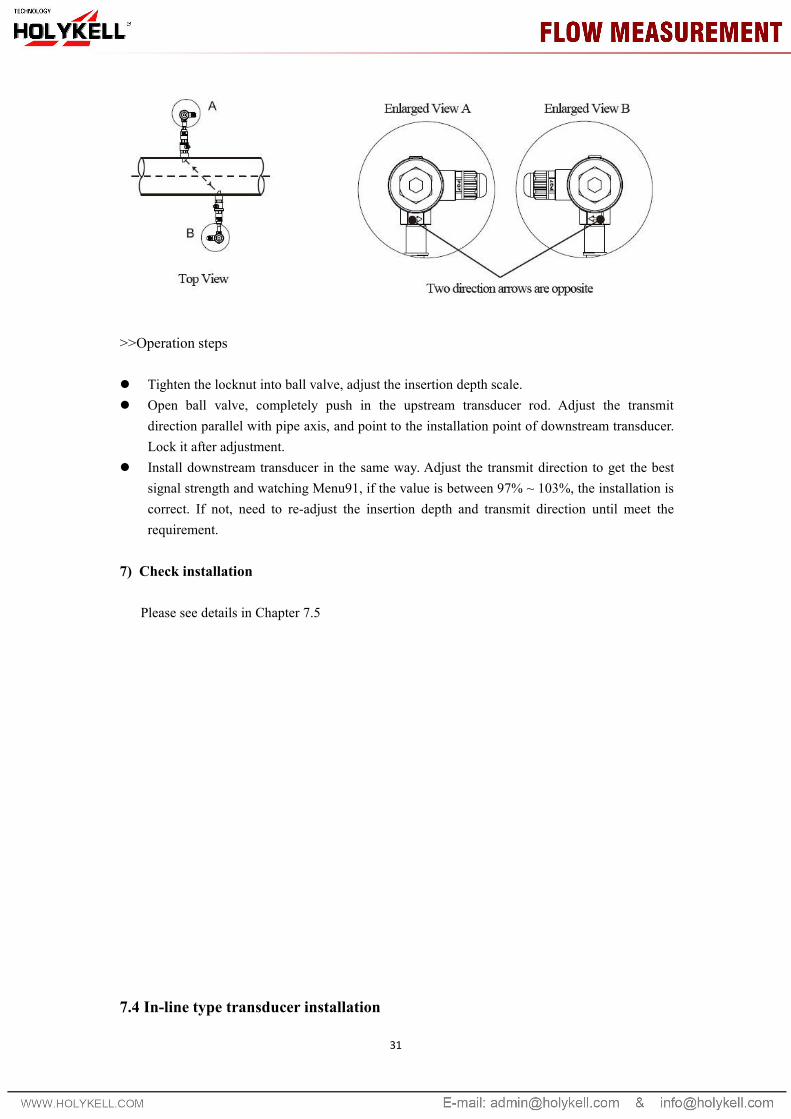
>> Transmit directionThere is a indicating arrow on the transducer junction box, the arrow direction on two
transducers should be opposite and parallel to the pipe axis.
31
>>Operation steps
Tighten the locknut into ball valve, adjust the insertion depth scale. Open ball valve, completely push in the upstream transducer rod. Adjust the transmit
direction parallel with pipe axis, and point to the installation point of downstream transducer.Lock it after adjustment.
Install downstream transducer in the same way. Adjust the transmit direction to get the bestsignal strength and watching Menu91, if the value is between 97% ~ 103%, the installation iscorrect. If not, need to re-adjust the insertion depth and transmit direction until meet therequirement.
7) Check installation
Please see details in Chapter 7.5
7.4 In-line type transducer installation

After choosing the installation point, install the transducer in the pipeline with companion flanges.Then connect the transducer to converter with special signal cable. Installation is complete.
1) Installation method
2) Check installation
Please see details in Chapter 7.5
7.5 Check Installation
33
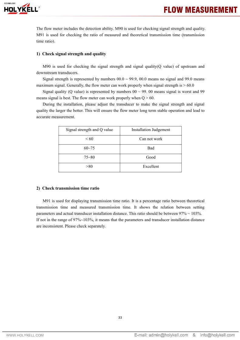
The flow meter includes the detection ability. M90 is used for checking signal strength and quality.M91 is used for checking the ratio of measured and theoretical transmission time (transmissiontime ratio).
1) Check signal strength and quality
M90 is used for checking the signal strength and signal quality(Q value) of upstream anddownstream transducers.
Signal strength is represented by numbers 00.0 ~ 99.9, 00.0 means no signal and 99.0 meansmaximum signal. Generally, the flow meter can work properly when signal strength is > 60.0
Signal quality (Q value) is represented by numbers 00 ~ 99. 00 means signal is worst and 99means signal is best. The flow meter can work properly when Q > 60.
During the installation, please adjust the transducer to make the signal strength and signalquality the larger the better. This will ensure the flow meter long term stable operation and lead toaccurate measurement.
Signal strength and Q value Installation Judgement
< 60 Can not work
60~75 Bad
75~80 Good
>80 Excellent
2) Check transmission time ratio
M91 is used for displaying transmission time ratio. It is a percentage ratio between theoreticaltransmission time and measured transmission time. It shows the relation between settingparameters and actual transducer installation distance. This ratio should be between 97% ~ 103%.If not in the range of 97%~103%, it means that the parameters and transducer installation distanceare inconsistent. Please check separately.

8. Finish Installation
1) Commonly used menus. M00 or M02 is for meter reading. M30~M33 is for unit selection.M40 is for selecting damping factor, generally 5~10 sec. M60 is for correcting time and date.M26 is for curing parameters.
2) To avoid signal reduction and improve anti-jamming ability, it is better to use thecustomized signal cable from flow meter manufacturer.
3) The length of cables between converter and transducer should be as short as possible,cannot exceed 200m.
4) The temperature and humidity of working environment should be in the range of technicalspecifications. Avoid direct sunlight on LCD.