Embed Size (px)
Citation preview

Constructive Solid Geometry based TopologyOptimization using Evolutionary Algorithm
Faez Ahmed, Bishakh Bhattacharya and Kalyanmoy Deb
Abstract Over the past two decades, structural optimization has been performed ex-tensively by researchers across the world. Most recent investigations have focusedon increasing the efficiency and robustness of gradient based optimization tech-niques and extending them to multidisciplinary objective functions. The existingglobal optimization techniques suffer with requirement of enormous computationaleffort due to large number of variables used in grid discretization of problem do-main. The paper proposes a novel methodology named as Constructive GeometryTopology Optimization Method (CG-TOM) for topology optimization problems. Itutilizes a set of nodes and overlapping primitives to obtain the geometry. A novelgraph based repair operator is used to ensure consistent design and real parametergenetic algorithm is used for optimization. Results for standard benchmark prob-lems for compliance minimization have been found to give better results than exist-ing methods in literature. The method is generic and can be extended to any two orthree dimensional topology optimization problem using different primitives.
1 Introduction
Structural optimization is the determination of the topology, shape and size of themechanism starting with a domain of material to which the external loads and sup-ports are applied [9]. Topology optimization of compliant mechanism can be consid-ered as determination of material connectivity among different ports such as input,output and support ports (boundary conditions). These special ports and other mate-rial intersection ports can be termed as nodes and the topology defines the compliantmechanism skeleton and connection between such nodes. It provides the flexibility
Bishakh BhattacharyaIndian Institute of Technology, Kanpur, e-mail: [email protected]
Kalyanmoy DebIndian Institute of Technology, Kanpur, e-mail: [email protected]
1

2 Faez Ahmed, Bishakh Bhattacharya and Kalyanmoy Deb
where both the shape of the exterior boundary and configuration of interior bound-aries can be optimized simultaneously.
Most of the existing methods in literature use a grid approach for domain dis-cretization. They use variables proportional to number of grid cells, and utilize gra-dient based methods to search for optimum topology. Hence the number of variablesused are large. Problems like point flexure and mesh dependency are found in suchmethods and are often dealt with using different filtering techniques. Mesh refine-ment further increases the number of variables.
The objective function is often the compliance, that is, the flexibility of the struc-ture under the given loads, subject to a volume constraint. The optimum distribu-tion of material is measured in terms of the overall stiffness of the structure suchthat the higher the stiffness the more optimal the distribution of the allotted mate-rial in the domain. Two major methods existing in topology optimization field arehomogenization and the solid isotropic material with penalization (SIMP) meth-ods. Comprehensive details of SIMP and related methods can be found in [1]. Fora continuum structure represented by a domain of finite elements and associatedboundary conditions, the compliance minimization topology optimization problemin SIMP can be expressed mathematically as: Find the optimal distribution of solidand void elements that would
min f (ρ) = uT Ku =Ne
∑j=1
u jT Kju j (1)
such that ∑Nej=1 ρ jVj ≤V0
where 0 < ρmin ≤ ρ ≤ 1
here f (ρ) represents the objective function which is total strain energy, ρ is thedesign variable vector of non-dimensional element densities, u the vector of globalnodal displacements and K is the global stiffness matrix. u j, Kj, ρ j and Vj are the jth
elements displacement vector, stiffness matrix, non-dimensional density and volumerespectively. Ne is the number of elements and V0 is the material available.
Genetic algorithms were used by Jakiela [5] for the optimal topology search ofcontinuum structures. The design space was discretized into small elements with allof the finite elements forming a binary-coded bit-string chromosome, 0 and 1 forabsence and presence of an element in the structure, respectively. To facilitate thetransmission of topology and shape characteristics across generations, Tai et al. [10]utilized spline based arrangements of skeleton and flesh surrounding the bones torepresent structural geometry. Other recent works in non-gradient methods includesimulated biological growth (SBG) [7], bidirectional ESO (BESO) [8] and cellularautomata [2, 6]. The usage of global optimization methods are generally not foundto perform at par with the local optimization methods [9].
Constructive Solid Geometry (CSG) is a technique widely used in solid mod-elling. It uses Boolean operators to combine simple objects called solids or prim-itives, constructed according to geometric rules, and form complex two or three

Constructive Solid Geometry based Topology Optimization 3
dimensional geometries. Simple shapes like rectangle, circle, ellipse or a genericpolygon can be used as a CSG primitives in 2-D. The boolean operations can besummarized as Union, Intersection and Difference as shown in Figure 1 (a).
The idea of utilizing CSG primitives for topology optimization provided the mo-tivation for the proposed technique. Using CSG, union of many primitives (rect-angular bars) can be taken to form complex shape segments. The material wherebar segments do not appear is left out as holes. This idea provides the backbone ofCG-TOM method.
Fig. 1 (a) CSG Boolean operations on 2-D primitives (b) Problem domain for cantilever with endloading
2 Methodology
The key idea to the methodology is to utilize a small set of points (nodes) and thereconnectivity to generate the compliant mechanism or structure. A generic topol-ogy can be seen as comprising of few joints connected by segments. The numberof joints and the number of segments connecting them may vary from one mecha-nism to other. The synthesis of compliant mechanisms has traditionally been viewedas a domain with presence or absence of holes. On the contrary, we propose touse a building block model where different segments (primitives) overlap to giveshape and volume to the final topology. The topology is completely defined by a setof n nodes and widths representing connectivity between each pair of nodes. Themethodology is explained through a topology optimization problem of a cantileversystem. The domain dimensions are 120mm× 40mm and a point load of 100 N isapplied at the edge as shown in Fig. 1 (b).

4 Faez Ahmed, Bishakh Bhattacharya and Kalyanmoy Deb
2.1 Algorithm Summary
The algorithm can be summarized in the following steps. In the next section, stepby step explanation along-with example figures is shown.
Step 1 Define k fixed nodesStep 2 Interpret variables to obtain positions of m nodesStep 3 Delaunay triangulation to obtain allowed connectivity between all nodesStep 4 Allot widths to triangle edges. Remove edges with negative widths.Step 5 Use CSG tool to obtain the topology after union of all barsStep 6 Use graph based repair operator to check and correct the topology.Step 7 Mesh the obtained topology using CSG supporting mesh generatorStep 8 Apply loads and boundary conditions at required nodesStep 9 Use finite element analysis to solve for deflection, stresses etc.Step 10 Read required output and return fitness and constraint values
2.2 Description
Having summarized the algorithm, we now give a step by step description of themethod.
In a generic topology optimization problem, after the actual problem formulation,the design engineer has a problem domain within which the final topology should beconstrained, a set of loads and a set of boundary conditions (like the location of sup-ports). After considering the boundary condition and loads, the user defines k fixednodes. These nodes represent the spatial locations where material must necessarilybe present. The point of application of loads (e.g. point force) or various boundaryconditions are usually taken as fixed nodes. As shown in Fig. 2 (a), three fixed nodes(shown by square marker) at (0,0), (120,0) and (0,40) are taken. Thereafter we takem nodes denoting joints, within the domain bounds as shown in Fig. 2 (a) by circularmarkers. The final mechanism may have any number of joints less than or equal tom. The n(= m+ k) points represent the ’joints’ in the mechanism.
To find the possible connections between joints, we use triangulation of the nodesas shown in Fig. 2 (b). This gives us the base skeleton. In our simulation we haveused Delaunay triangulation [3] between the nodes.
In the current work, we have utilized rectangular shaped CSG primitive of variousdimensions and union operation as boolean operator. After obtaining the skeleton,some of the edges are replaced by rectangular bars. In figure 3 (a), all the skeletonedges are replaced by bars of different width and CSG union of all such bars istaken to obtain the topology. Edges which are replaced by bars and the width of thebars is controlled by optimization algorithm. It can be noticed that the addition ofwidth to each bar leads to material overlap between bars corresponding to previouslynon-intersecting edges. Width of one bar may completely overshadow another joint

Constructive Solid Geometry based Topology Optimization 5
after union operation. We have done CSG calculations using commercial softwareMATLAB alongwith utilizing its mesh generator.
Fig. 2 (a) Fixed and variable nodes within domain (b) Delaunay triangulation of the nodes
Fig. 3 (b) shows the resultant geometry. It can be observed that using only a sim-ple rectangular bar primitive various complex features and holes of different sizescan be obtained. It is possible that a small portion of the geometry may go outsidethe box formed by the domain. Hence we use the CSG operation of subtraction andany portion outside the domain is trimmed.
Next, meshing of the obtained geometry is done using CSG supporting meshgenerator and load and boundary conditions are applied. Post meshing, the 2-D FEAcalculation is done and it is found that the tip of the given geometry deflects by2.086 mm and occupies 62.83% volume. The connectivity between nodes can alsobe visualized in the form of a connected graph between the numbered nodes whichwill be utilized for graph repair operator. ABAQUS software has been used for finiteelement calculations.
In single objective compliance minimization problems, the amount of materialavailable to form the optimum topology is limited. For e.g. a problem may state tofind the optimum topology of a cantilever system shown in Fig. 1 (b) with mini-mum mean compliance using only 50% material. Hence volume occupied by thetopology acts as a constraint and any topology using more than 50% volume willbe deemed infeasible. Initial trial runs in our study denoted that many geometriestend to be infeasible, hence slowing the convergence of optimization run. Speciallywhen the optimization is near convergence, most of the population members havevolume close to 50% boundary and any new member created with slight variation ofbar width or node position may slightly increase from the volume limit and wouldbecome infeasible. Hence a volume correction operator is proposed to improve GAconvergence.
After the formation of final geometry, the volume is calculated. If the volume isabove the constraint value (say 60%) the amount of deviation ε from constraint iscalculated. If ε ≤ δ , all the width of bars are reduced by a ratio, such that the finaltopology satisfies the volume constraint. In our simulations, we have taken δ = 15.The volume operator was found to be very effective in improving convergence time.After the volume correction, FEA analysis is done on feasible geometry. To illustratethe operator, we again take the same example as shown in Fig. 3 (b). The topologyvolume was found to be 62.83% which violated the constraint of 50%. The widths

6 Faez Ahmed, Bishakh Bhattacharya and Kalyanmoy Deb
Fig. 3 (a) Mechanism formed by replacing edges with bars of different widths (b) Geometry aftermeshing
of all bars were reduced such that its volume comes just below 50%. Fig.4 (a) showsthe mesh of geometry with reduced widths in original and deflected positions. Thenew geometry with volume 49.97% satisfies the volume constraint and deflects by2.972 units.
In the above methodology, the position of the nodes and the widths of the bars arecontrolled by the optimization algorithm to give different geometries. If the widthvariable between two nodes is negative or the connection is absent from the baseskeleton, then the segment between those nodes is removed. Hence the intersectionof remaining segments gives the final geometry. The benefit of removing connec-tions depending on variable values is that some nodes can be completely discon-nected and very simple geometries can also be obtained. We now discuss the repairoperation to deal with inconsistent geometries.
Fig. 4 (a) Final deflected and original geometry after volume correction and FEA analysis (b)Inconsistent geometry to demonstrate repair algorithm
3 Graph based Geometry Repair
3.1 Discussion
The optimization algorithm initializes the variables randomly. It is possible thatmany bars are absent such that the geometry formed after CSG union is discon-nected or broken. A disconnected geometry can be formed in following ways

Constructive Solid Geometry based Topology Optimization 7
• The point of application of load is not connected to the geometry• The geometry is not connected to a fixed nodes corresponding to point of appli-
cation of boundary conditions• There are hanging sections in space, that is some section is not connected to any
node in main geometry
In any such scenario, the fitness evaluation function must detect inconsistenttopology and take corrective actions before FEA analysis. Otherwise the FEA anal-ysis will give error and optimization will prematurely terminate. Rejecting or penal-ization of such broken geometries is also not desirable as it will reduce the feasiblegeometries and many function evaluations may be wasted in each generation. Hencewe have employed a graph theory approach for anomaly detection and to take cor-rective action by repairing the geometry.
3.2 Repair algorithm
A brief overview of the algorithm is given below. Here the geometries are viewedas graph of connected nodes. A group of interconnected nodes is termed as a Set.To ensure connected geometry between load and boundary conditions as well as nodisconnected section, the algorithm aims to form a single set containing all the fixednodes. In case of absence of such a set, geometry is repaired by adding minimumpossible segments to form the connected set. Other disconnected sets are eliminated.
Step 1 Find all Sets of interconnected nodesStep 2 Find the sets containing fixed nodes. These are termed Fixed Sets If singlesuch set exists, go to Step 7Step 3 Using the initial triangulation data, find the connectivity between eachpair of sets. A set ’A’ is connected to set ’B’ if any of its nodes is allowed to beconnected to any of the nodes of set ’B’ by triangulationStep 4 Obtain the graph of connectivity between sets. Weight of connection be-tween two nodes is the length of the shortest segment which can connect themStep 5 Using BFS (Breadth first search) from each set in the graph, find theminimum connections required to join all the Fixed SetsStep 6 Add segment between the corresponding nodes between the sets to forma single connected setStep 7 Ignore all other sets and form the final geometry using the Fixed Set
3.3 Repair Example
To illustrate the algorithm, an example broken geometry is derived from the examplein Fig. 3 by randomly removing some connections. The broken geometry is shownin Fig. 4 (b). Here all the three fixed nodes are disconnected from each other and

8 Faez Ahmed, Bishakh Bhattacharya and Kalyanmoy Deb
two disconnected bars are also present. Using the algorithm, first the graph of nodesis formed and each connected set is identified as shown in Fig. 5. Eight differentSets are marked in it of which the first three are the Fixed Sets. Fig. 6 (a) showsthe connectivity between the eight sets. Using BFS, the shortest path connecting theFixed Sets is calculated and is shown in the figure by bold lines. Once the pair of setsrequired to be connected is recognized, the nodes connecting them with minimumsegment length are identified and final geometry is repaired. Two corrections arerequired. After applying the corrections, all other sets are ignored, hence all otherdisconnected bars are eliminated from the final topology. Fig. 6 (b) shows the twobar segments added by the repair operator. The above algorithm ensures that even ifa direct connection between fixed sets is not possible, still the shortest path is foundthrough some intermediate set. BFS from each set ensures no bias.
Fig. 5 Connectivity graph of nodes in broken geometry showing connected Sets
Fig. 6 (a) Graph of Sets connected by connections which were previously absent (b) Segmentadded to repair geometry from graph
Constructive Solid Geometry based Topology Optimization 9
4 Single Objective Evolutionary Optimization
We have used Genetic Algorithms [4] to solve the optimization problem. The GAcode was integrated with MATLAB CSG tool and ABAQUS FEA solver to convertreal variables to geometry, geometry to finite element triangular mesh and finallyafter carrying the FEA analysis with given loads and boundary conditions, readingthe gene fitness from FEA output file for every function evaluation. From the dis-cussions in Section 2, it can be seen that solving any topology optimization problemwould initially require the user to decide on number of variable nodes. The fixednodes depend on problem information. Hence, in a problem with m variable nodesand k fixed nodes, the total number of GA variables required will be 2×m+
�m+k2
�.
The 2×m variables represent the node positions and there variable bounds dependon domain boundary and the
�m+k2
�represent the widths between each pair of num-
bered nodes.In the current study we have solved single objective compliance minimization
problem using real valued genetic algorithm. The initial population is generatedrandomly within the variable bounds specified. The next generation of the popula-tion is computed using the fitness of the individuals in the current generation. Binarytournament selection, polynomial mutation and SBX crossover are used. The generepresenting the m variable nodes is sorted with respect to there x co-ordinates asshown in Fig. 3 (b) and nodes are numbered sequentially.
Since the node numbering is decided on basis of x co-ordinates, the widths arealso mapped accordingly. The crossover between the co-ordinates of node i of par-ent A occurs with corresponding node i in parent B. Similarly the width crossoverbetween parent A and B genes would occur corresponding to bar between nodes(i, j) in both.
4.1 Case Study 1
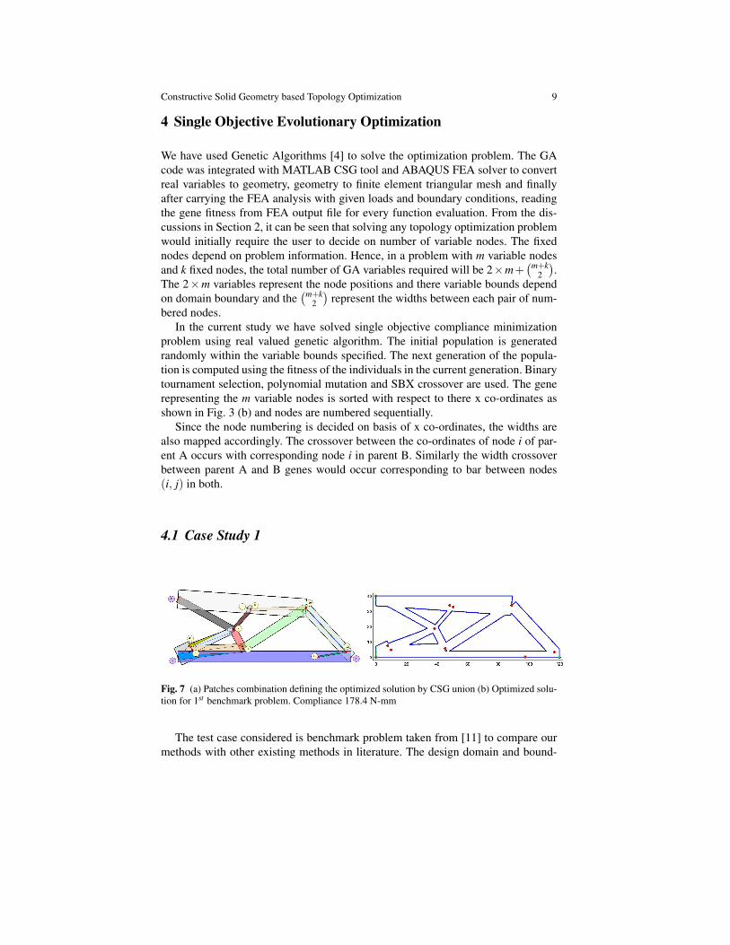
Fig. 7 (a) Patches combination defining the optimized solution by CSG union (b) Optimized solu-tion for 1st benchmark problem. Compliance 178.4 N-mm
The test case considered is benchmark problem taken from [11] to compare ourmethods with other existing methods in literature. The design domain and bound-

10 Faez Ahmed, Bishakh Bhattacharya and Kalyanmoy Deb
1
40
80
120
160
Best Fitness
Fig. 8 Variation of fitness and mean volume with generations showing evolution of geometry
aries for the compliance minimization problem was shown in Fig. 1 (b) for a can-tilever system. Here the domain is 120mm× 40mm and a point load of 100 N isapplied at the end with material constraint V/V0 ≤ 0.5. The volume fraction in-equality constraint is V/V0 ≤ 0.5 and fitness is reported in N-mm. The material datafor both benchmark test are E = 10 GPa and ν = 0.3
Three fixed nodes have been taken and nine variable nodes. Hence the total num-ber of real variables are 84. A population size of 40 is taken and GA is run for 200generations. The optimized solution for benchmark test using CG-TOM has beenshown in Fig.7 (b). [11] compares the different methods and filtering schemes forcompliance minimization on this domain and reports 179.1 N-mm mean complianceas minimum value. The fitness obtained using CG-TOM of 178.4 N-mm is better.Fig.7 (a) shows the primitive bars that combine to form this optimized solution.
The progress of optimization can be observed by analyzing the improvement offitness with each generation. In Fig. 8 the variation of fitness of best populationmember is shown with generations. Mean volume of entire population is also cal-culated for each generation and plotted. It can be seen that although the problemhas inequality constraint, the volume of entire population lies near the constraintboundary. The sharp dip in volume is explained by the usage of volume repair oper-ator which helps the population members to remain feasible.
To get a further insight into the evolution of design, we look at the best populationmembers after each interval of 40 generations in Fig. 8 during the optimizationprocess. It can be visually seen that GA recognizes the optimum geometry shapequickly and thereafter small shape variations of bar shape lead to the optimizedsolution. It can also be seen that the position of nodes gets fixed quickly definingthe basic skeleton.
Constructive Solid Geometry based Topology Optimization 11
4.2 Case Study 2
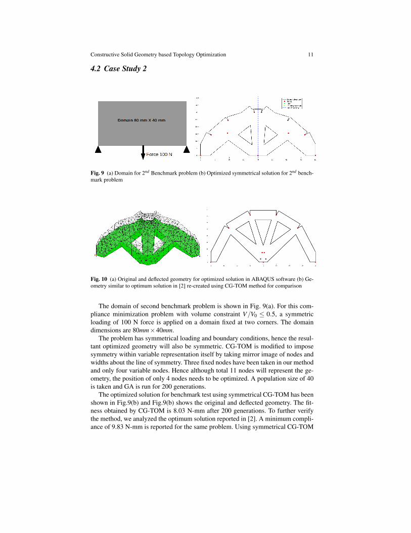
Fig. 9 (a) Domain for 2nd Benchmark problem (b) Optimized symmetrical solution for 2nd bench-mark problem
Fig. 10 (a) Original and deflected geometry for optimized solution in ABAQUS software (b) Ge-ometry similar to optimum solution in [2] re-created using CG-TOM method for comparison
The domain of second benchmark problem is shown in Fig. 9(a). For this com-pliance minimization problem with volume constraint V/V0 ≤ 0.5, a symmetricloading of 100 N force is applied on a domain fixed at two corners. The domaindimensions are 80mm×40mm.
The problem has symmetrical loading and boundary conditions, hence the resul-tant optimized geometry will also be symmetric. CG-TOM is modified to imposesymmetry within variable representation itself by taking mirror image of nodes andwidths about the line of symmetry. Three fixed nodes have been taken in our methodand only four variable nodes. Hence although total 11 nodes will represent the ge-ometry, the position of only 4 nodes needs to be optimized. A population size of 40is taken and GA is run for 200 generations.
The optimized solution for benchmark test using symmetrical CG-TOM has beenshown in Fig.9(b) and Fig.9(b) shows the original and deflected geometry. The fit-ness obtained by CG-TOM is 8.03 N-mm after 200 generations. To further verifythe method, we analyzed the optimum solution reported in [2]. A minimum compli-ance of 9.83 N-mm is reported for the same problem. Using symmetrical CG-TOM

12 Faez Ahmed, Bishakh Bhattacharya and Kalyanmoy Deb
method with four variable nodes, a visually similar solution (exact dimensions werenot available) to there optimum solution was generated as shown in Fig.10(b). Thefitness calculated using our method for this geometry was 9.82 N-mm which wasclose to the reported fitness of 9.83 N-mm of original geometry in [2]. This verifiedthe FEA calculations of the proposed method.
5 Conclusion
The current work ventures into proposing a new technique for topology optimiza-tion. In the current work,the proposed technique christened CG-TOM uses simplerectangular primitives for compliance minimization problem test cases. It was foundto give better results than existing literature in both cases. The current work opensup many possibilities of usage of CSG techniques for topology optimization andinverse finite element problems by integrating CSG modelling technique with opti-mization. Further research can focus on post-processing to obtain smooth geome-tries, extension of method to three dimensional problems using 3-D primitives andproposing more efficient GA algorithms to give optimized solutions within low bud-get of function evaluations.
References
1. M.P. Bendsøe and O. Sigmund, Topology optimization: theory, methods, and applications,Springer Verlag, 2003.
2. B. Bochenek and K. Tajs-Zielinska, Novel local rules of cellular automata applied to topologyand size optimization, Engineering Optimization 44 (2012), no. 1, 23–35.
3. M. De Berg, O. Cheong, and M. Van Kreveld, Computational geometry: algorithms and ap-plications, Springer-Verlag New York Inc, 2008.
4. D.E. Goldberg, Genetic algorithms in search, optimization, and machine learning, Addison-wesley, 1989.
5. M.J. Jakiela, C. Chapman, J. Duda, A. Adewuya, and K. Saitou, Continuum structural topol-ogy design with genetic algorithms, Computer Methods in Applied Mechanics and Engineer-ing 186 (2000), no. 2, 339–356.
6. E. Kita and T. Toyoda, Structural design using cellular automata, Structural and Multidisci-plinary Optimization 19 (2000), no. 1, 64–73.
7. C. Mattheck and S. Burkhardt, A new method of structural shape optimization based on bio-logical growth, International Journal of Fatigue 12 (1990), no. 3, 185–190.
8. OM Querin, GP Steven, and YM Xie, Evolutionary structural optimisation (eso) using a bidi-rectional algorithm, Engineering Computations: Int J for Computer-Aided Engineering 15(1998), no. 8, 1031–1048.
9. G.I.N. Rozvany, A critical review of established methods of structural topology optimization,Structural and Multidisciplinary Optimization 37 (2009), no. 3, 217–237.
10. K. Tai, G.Y. Cui, and T. Ray, Design synthesis of path generating compliant mechanisms byevolutionary optimization of topology and shape, Journal of Mechanical Design 124 (2002),492.
11. S. Xu, Y. Cai, and G. Cheng, Volume preserving nonlinear density filter based on heavisidefunctions, Structural and Multidisciplinary Optimization 41 (2010), no. 4, 495–505.
View publication statsView publication stats